OPERATION & MAINTENANCE MANUAL SYNCHRONOUS GEARLESS MACHINES T32S/T32/T32L
|
|
|
- Rodger Long
- 5 years ago
- Views:
Transcription


1 OPERATION & MAINTENANCE MANUAL 3005/ /12 en Ed SYNCHRONOUS GEARLESS MACHINES T32S/T32/T32L
2 CONTENTS 1. SAFETY RULES 1.1. General safety instructions 1.2. Safety precautions 1.3. Intended use 1.4. Packing and handling 1.5. Storage 2. PRODUCT DESCRIPTION 2.1. Main features 2.2. Traction machine name details 2.3. Technical data 2.4. Feedback encoder 2.5. Holding brake 2.6. Brake drawing 09D Brake drawing 10D Brake drawing 10D Nameplate data 3. INSTALLATION 3.1. Safety precautions 3.2. Fastening the traction machine 4. ELECTRICAL CONNECTIONS 4.1. General 4.2. Connecting the motor 4.3. Connecting the brake 4.4. Connecting the encoder Encoder connection diagrams Replacing the encoder 5. TESTING THE BRAKE SYSTEM 5.1. Overload test 5.2. Component failure test 6. MAINTENANCE 6.1. Maintenance program 6.2. Safety precautions during maintenance 6.3. Troubleshooting 7. DECLARATION OF CONFORMITY TO STANDARD EN 81-1 SECT.12.4 FOR KEB BRAKE 8. EC DECLARATION OF CONFORMITY FOR KEB BRAKE ANNEXES a) EC Declaration of Conformity for Traction Machine b) KEB Brake Manual c) KEB TÜV certification The operating instructions in this manual refer to T32S-T32-T32L gearless traction machines. LAFERT S.p.A. reserves the right to amend or change the contents of this manual and product details without prior notice. LAFERT S.p.A. reserves the right to make technical changes improving the product's performance and safety standards without prior notice. OPERATION AND MAINTENANCE MANUAL T32S-T32-T32L 3005/12 en- Ed. 02/2012 1
3 1. SAFETY RULES 1.1 GENERAL SAFETY INSTRUCTIONS This section explains the symbols used in this manual to describe the possible consequences of failure to observe the safety rules. SYMBOLS USED IN THIS MANUAL This symbol means that failure to follow the relative instructions or to take the necessary precautions may lead to death or serious injuries to persons and irreversible damage to property. This symbol means that failure to follow the relative instructions or to take the necessary precautions may lead to death or serious injuries to persons and irreversible damage to property. This symbol means that failure to follow the relative instructions or to take the necessary precautions may lead to damage to property. This symbol means that the relative instructions are important for the correct use of the product and that failure to follow them may lead to serious damage. 1.2 SAFETY PRECAUTIONS These traction machines have been designed and manufactured to be used as lifting gear for lifts and service elevators in compliance with the relative standards (EN 81-1 and subsequent). Any other use should be considered improper and not authorized by Lafert SpA. Additionally, Lafert traction machines should never be used to lift persons or objects on lifting systems that are not built in accordance with the relevant regulations and that failed to pass the required tests. Lafert traction machines are not delivered ready for use. They may be used only after being installed on the relevant machines or systems and after ensuring their safety by means of safety grids, barriers, construction features or other devices, depending on the application. Scheduled and/or special maintenance may be carried out only by qualified and authorized personnel. Maintenance should be performed following the instructions given in this manual or provided in any other supporting documentation supplied by LAFERT S.p.A. The personnel should be adequately instructed on the product's installation, assembly and commissioning. T32S-T32-T32L gearless traction machines are designed to work inside close spaces, such as lift wells, where access is allowed only to qualified and authorized personnel. The instructions contained in this manual or in any other documentation supplied should be followed at all times in order to avoid injuries or damage to persons and/or to the installation. T32S-T32-T32L gearless traction machines are not delivered ready for use. They may be used only after being correctly installed and connected to an operating panel. Before putting the machine into service, make sure that all the conditions for the proper operation of the motor and the brake have been applied. IT IS EXTREMELY DANGEROUS TO PUT YOUR HANDS near the traction sheave or the lifting ropes. Some parts of the machine can become very hot during operation (70/80 C). Therefore, it is MANDATORY to ensure that nobody can accidentally touch these parts for maintenance or repairs before a period of time sufficient for the parts to cool down to temperatures suitable for direct contact. During installation, inspection or maintenance work, DO NOT WEAR necklaces, bracelets or loose items of clothing, such as scarves or wide-sleeved shirts, that might get caught in moving parts. Repairs may only be carried out by LAFERT personnel. Unauthorized opening or tampering may result in serious damage to persons and/or to the machine itself. T32S-T32-T32L gearless traction machines are not designed to be powered directly from the mains. They must be connected to a frequency regulator. Connecting the traction machine directly to the power mains may destroy the machine. High voltages are present on the connection terminals when the motor is running. OPERATION AND MAINTENANCE MANUAL T32S-T32-T32L 3005/12 en- Ed. 02/2012 2
4 1.3 INTENDED USE The T32S-T32-T32L is a state-of-the-art traction machine developed in compliance with the latest technical standards and safety regulations. It may be used only in accordance to the instructions in this manual and with all the relevant safety devices described. LAFERT S.p.A. shall not accept any warranty or liability claims for personal injury or property damage resulting from the following causes: Improper use of the T32S-T32-T32L traction machine Improper installation, operation and/or maintenance of the T32S-T32-T32L traction machine Operation of the T32S-T32-T32L traction machine without the relative protection and safety devices Using the product not in accordance with the instructions given in this manual Unauthorized changes made to the T32S-T32-T32L traction machine Insufficient monitoring of parts subject to wear or failure to perform scheduled maintenance Emergencies or situations caused by external forces or force majeure 1.4 PACKING AND HANDLING When handling the traction machine, only the methods described below may be used. Always make sure that the rated capacity of the transport and lifting apparatus is sufficient to carry the weight of the machine and its packing. Transport on pallet. Transport without pallet, lifting by hook. The personnel in charge of handling the machine must wear safety gloves and shoes. Clear the operating area before lifting or moving the machine or any part of it. Also, provide an adequate safety margin around the working area to prevent damages to nearby persons or property. The machine is delivered wrapped in thermoplastic material to protect all machine parts. If requested, the machine can be packed in a wooden box or crate for additional protection against bumps or external agents. Use a forklift to lift the machine (see figure). Follow the instructions printed on the packing before moving or opening the crate. To lift the machine use the eyebolts provided. Their location is indicated on the machine. Do not attach anything to the motor. Observe all the precautions that apply to suspended loads. 1.5 STORAGE When moving the machine, follow all the relevant safety rules and regulations, taking into account the load s weight and its proper balancing. Two eyebolts are provided to facilitate handling. The eyebolts are designed to carry the weight of the T32S-T32-T32L traction machine only. Additional loads are not allowed. Store the machine in a closed, dry, dust-free, well-ventilated place free from vibrations. The storage temperature should be between -20 C and 60 C. Do not store the traction machine in the open and/or in places exposed to the elements. Avoid excessive storage periods (recommended: max. 1 year). After prolonged periods of storage (more than 3 months), make the motor run at low speed (less than 20 rpm) to redistribute the lubricating grease inside the bearings. Measure the windings insulation resistance before starting the machine after a prolonged period of storage. If the resistance has dropped below 1kΩ, the windings will have to be dried. This can be done by connecting the phases of the traction machine to a suitable voltage generator and allowing a current of 45% the rated current to circulate in the phases for several hours in order to heat the windings up to about 80 C. This will remove any condensate that may have formed during the storage period. OPERATION AND MAINTENANCE MANUAL T32S-T32-T32L 3005/12 en- Ed. 02/2012 3
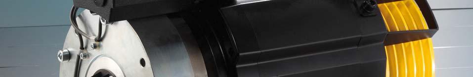
5 2. PRODUCT DESCRIPTION 2.1. MAIN FEATURES The T32S-T32-T32L units are gearless traction machines designed for operating lifts (elevators). They can be installed directly inside the lift well and do not require a dedicated machine room. Thanks to their compact dimensions and design concept based on the projection of the traction sheave they allow very good size-to-power ratios. These machines are mainly designed to be installed at the top of the lift well, where their small size makes it easy to arrange the various machine parts. T32S-T32-T32L traction machines are equipped with permanent-magnet synchronous motors, allowing excellent performances in terms of: Low noise levels High energy efficiency High dynamic performance and optimal control of motion profiles High power-to-weight and torque-to-weight ratios Being equipped with high-quality shielded bearings with life lubrication and having no parts that work by friction, T32S-T32-T32L machines require very little maintenance. Feedback for the traction machine is provided by a high-quality encoder which, used in combination with a frequency regulator, allows sophisticated motion control and accurate management of the car s position within the entire speed range. Special attention was given to sizing the electromagnetic section, which was optimized by finite-element analyses to achieve excellent performance in terms of torque and low-speed ripple reduction. Their advanced design and the quality of the construction materials contribute to place T32S-T32-T32L units among the sturdiest and most reliable traction machines TRACTION MACHINE NAME DETAILS This section explains the meaning of the designation given to the traction machine (shown as Type in the nameplate). This designation always appears on the machine s nameplate (see Par. 2.7). T 3 2 L Machine size = T32S, T32, T32L Sheave diameter (240; 320 mm) System speed = 1.0 / 1.6 m/sec OPERATION AND MAINTENANCE MANUAL T32S-T32-T32L 3005/12 en- Ed. 02/2012 4
6 2.3. TECHNICAL DATA All T32S-T32-T32L traction machines are equipped with 24-pole permanent-magnet motors. The main technical details of the traction machine* are summarized in the table below: Type Max payload [kg] Roping Rated torque [Nm] speed [m/s] Traction sheave Ø mm Max ropes nr x Ø mm T32S : x 8 T32S : , x 8 T32S : x 6,5 T32S : , x 6,5 T : x 8 T : , x 8 T : x 6,5 T : , x 6,5 T32L : x 8 T32L : , x 8 T32L : x 8 T32L : , x 8 T32L : x 6,5 T32L : , x 6,5 T32S D : x 8 T32S D : , x 8 T32S D : x 6,5 T32S D : , x 6,5 T D : x 8 T D : , x 8 T D : x 6,5 T D : , x 6,5 T32L D : x 8 T32L D : , x 8 T32L D : x 6,5 T32L D : , x 6,5 *for the motor data please refer to attached data sheet The resistance and inductance details of the specific motor installed, which are used for setting the drive correctly, are shown on the machine s nameplate (see Par. 2.9) FEEDBACK ENCODER All T32S-T32-T32L traction machines are equipped with one of the following encoders: Encoder Description Heidenhain ECN413 Absolute encoder EnDat 2.1 Heidenhain ERN487 Encoder SinCos 2048 Heidenhain ERN421 Incremental encoder TTL 4096 pulses/rev. Heidenhain ERN431 Incremental encoder HTL 4096 pulses/rev. See Par. 4.4 for information on electrical connections. OPERATION AND MAINTENANCE MANUAL T32S-T32-T32L 3005/12 en- Ed. 02/2012 5
7 2.5. HOLDING BRAKE All T32S traction machines are equipped with a holding brake having the following features: Type Max. braking torque [Nm] Standby voltage [Vdc] Standby power [W] Opening overvoltage [Vdc] Microswitch 09D x Nr. 2 (2x3 wires) All T32 traction machines are equipped with a holding brake having the following features: Type Max. braking torque [Nm] Standby voltage [Vdc] Standby power [W] Opening overvoltage [Vdc] Microswitch 10D x Nr. 2 (2x3 wires) All T32L traction machines are equipped with a holding brake having the following features: Type Max. braking torque [Nm] Standby voltage [Vdc] Standby power [W] Opening overvoltage [Vdc] Microswitch 10D x Nr. 2 (2x3 wires) The traction machine is supplied with the brake locked by 4 M10x80 hex screws (see drawing, Par. 2.6, 2.7 and 2.8). See Par. 4.3 for information on the brake s electrical connections. Upon request, the brake can be supplied with release levers (optional). OPERATION AND MAINTENANCE MANUAL T32S-T32-T32L 3005/12 en- Ed. 02/2012 6

8 2.6. BRAKE DRAWING 09D OPERATION AND MAINTENANCE MANUAL T32S-T32-T32L 3005/12 en- Ed. 02/2012 7

9 2.7 BRAKE DRAWING 10D OPERATION AND MAINTENANCE MANUAL T32S-T32-T32L 3005/12 en- Ed. 02/2012 8

10 BRAKE DRAWING 10D OPERATION AND MAINTENANCE MANUAL T32S-T32-T32L 3005/12 en- Ed. 02/2012 9
11 2.9 NAMEPLATE INFORMATION In compliance with the Machinery Directive, T32S-T32-T32L traction machines are provided with a nameplate with details of the basic information required for the motor s correct operation. The table below shows the nameplate s layout and the more important data Machine type Rated current LAFERT SPA Via Kennedy 43 I S. Donà di Piave (VE) Made in Italy Type T ph Mot. N Th. Cl.F IP44 S3-40% Mn = 480 Nm In = 9.4 A 2.2 kw Speed = 115 min -1 Freq = 23 Hz Brake = Type 10D8 2 x 450 Nm 200/105 Vdc R f-f = 6.1 Ω Protector Type PTC 140 C L f-f = 60 mh Ke = 10.4 Vs Kt = 18.0 Nm/Amp Weight = 120 Kg Serial no. Rated torque Frequency R f-f L f-f K e K t = resistance on winding terminals (phase-to-phase) [Ω] = inductance on winding terminals (phase-to-phase) [mh] = voltage coefficient [Vs] = torque coefficient [Nm/Amp] Weight 3. INSTALLATION 3.1. SAFETY PRECAUTIONS Make sure that all the prescribed safety measures have been applied before installing the traction machine. Before proceeding to install the machine, check the installation base and make sure it is adequately sized. If it is not, do not install the machine. The traction machine may be installed and electrically connected only by qualified and trained technical personnel. Bear in mind that T32S-T32-T32L traction machines are designed to be installed at the top of the lift well, where the space is restricted and working conditions are not comfortable. The encoder is located at the back of the machine; leave enough working space between the machine and the wall to replace the encoder FASTENING THE TRACTION MACHINE Fasten the machine to the base using 4 M16 bolts having strength class The tightening torque for this class is 300Nm. In order to reduce vibrations, place a rubber mat between the machine and the base. The maximum allowed deviation from planarity for the supporting surface is 0.2mm. Make sure the base is solid and adequately sized. If it is not, do not install the traction machine. The load applied by the ropes on the traction machine should have no lateral components in order not to apply a shearing stress on the fastening bolts. The maximum allowed deviation from verticality is 10. Place the ropes on the traction sheave only after fastening the machine and engaging the brake. The traction machine is equipped with a rope slip-off guard. After placing the ropes, set the guard at a distance from the rope of no more than 1.5mm. OPERATION AND MAINTENANCE MANUAL T32S-T32-T32L 3005/12 en- Ed. 02/

12 4. ELECTRICAL CONNECTIONS 4.1. GENERAL The traction machine may be electrically connected only by qualified personnel. After connecting the machine and before using it in any way, check the electrical insulation of the terminal box and the operating panel. Before making any connections, make sure that: The connection cables are suitable for their specific application in terms of voltages and currents. The cables are correctly installed and not susceptible to twisting, tensile or shearing strains that might affect their characteristics. The protective conductor has Protection Class 1 and is properly connected to the earthing system. There is no foreign matter or dirt inside the terminal box. The terminal box is properly sealed and the cable passages prevent the entry of dirt or dust. The motor insulation system is adequately sized for connection to frequency regulators by DC bus having a maximum voltage of 800V. The maximum acceptable rate of voltage rise (du/dt) for the motor is 4kV/us. In case that value is exceeded, suitable reactors should be introduced in the inverter-motor connection. The maximum acceptable overvoltage at the machine s terminals is 1.3kV. The figure below shows the general wiring diagram of the motor, the PTC thermal circuit-breaker and the brake. These connections are made in the terminal box after removing the terminal box cover. Inside the terminal box cover there is a figure of the connection diagram shown below. The earthing connection is made to either of the two screws located in the terminal box cover. OPERATION AND MAINTENANCE MANUAL T32S-T32-T32L 3005/12 en- Ed. 02/


13 4.2. CONNECTING THE MOTOR The electrical connections to the motor phases and the connection to the winding temperature sensor (PTC 140 C) are shown inside the terminal box. The connection cable for the phases and the protective conductor must have a cross-section suitable for the rated current of the machine as outlined in the table below. Cross-section [mm 2 ] Max. rated current S3-40% ,5 24 2, Data referred to PVC shielded cables at max. ambient temperature of 40 C. We recommend using oil-resistant, flame-resistant, shielded power cables for brushless motors, with PVC sheathing and designed for fixed laying. The motor cable must be a shielded cable with 3 poles + earth + shielding. Make sure the cable terminations are fitted with the right terminals for connecting to the terminal box. Make sure the U, V, W connection order on the motor is the same as on the inverter output. If this order is not respected the traction machine will not operate correctly, causing inverter failure. For safety reasons it is very important to properly connect the earth cable CONNECTING THE BRAKE The traction machine is delivered without a separate power supply for the brake. The power supply for the brake must be provided by the user/installer. The overexcitation voltage should be 205 Vdc for a period of about 2 sec. The brake s standby voltage is 105 Vdc. The maximum voltages and currents allowed on the microswitch terminals are as follows: o AC power supply, 250 Volt / 5 Amp. o DC power supply, 30 Volt / 5 Amp. See the relative section in the brake manual for further details. The electrical connections for the brake s power supply and the two microswitches are shown inside the terminal box. Make sure the cable terminations are fitted with the right terminals for connecting to the terminal box. See the relative section in the brake manual for further details. OPERATION AND MAINTENANCE MANUAL T32S-T32-T32L 3005/12 en- Ed. 02/
14 4.4. CONNECTING THE ENCODER T32S-T32-T32L traction machines are equipped with one of the following encoders: 1) Heidenhain Encoder ECN413 (EnDat 2.1) 2) Heidenhain Encoder ERN487 (SinCos) 3) Heidenhain Encoder ERN421 (TTL 4096 pulses/rev.) 4) Heidenhain Encoder ECN431 (TTL 4096 pulses/rev.) The encoder connection cable is located at the back of the traction machine. The encoder connection cable is supplied without the connector. Make sure that the encoder cable does not pass close to the motor connection cable, in order to avoid disturbances that would interfere with the position measuring system. Due to the nature of permanent-magnet synchronous machines, the absolute position of the encoder relative to the pulley shaft must be individually determined on each traction machine. For further details please refer to the Commissioning Manual of the drive system installed. The encoder is the most delicate part of the traction machine. Be careful not to bump the encoder against hard objects during handling, fastening or commissioning. When positioning the traction machine, bear in mind that the encoder can be accessed only from the back of the machine. Be sure to leave enough space to service or replace the encoder. The connection to the encoder depends on the type of encoder used, according to the following connection diagrams ENCODER CONNECTION DIAGRAMS Follow the connection diagram relative to the encoder actually installed on the traction machine. The 3 relevant connection diagrams are shown below: Heidenhain Encoder ECN413 (EnDat 2.1) Heidenhain Encoder ERN487 (SinCos) OPERATION AND MAINTENANCE MANUAL T32S-T32-T32L 3005/12 en- Ed. 02/

15 Heidenhain Encoder ERN421 (TTL 4096 pulses/rev.) and Heidenhain Encoder ECN431 (HTL 4096 pulses/rev.) REPLACING THE ENCODER Replace the encoder only if absolutely necessary due to an encoder fault or malfunction. When installing a new encoder, the offset value needs to be adjusted with a specific procedure that depends on the type of inverter. The encoder can be accessed only from the back of the machine. To gain access to the encoder housing, unscrew the cable gland on the plastic protective cover through which the cable passes and remove the cover. The encoder cable is fixed to the encoder. On encoders of the ERN4xx series the cable cannot be detached from the encoder. Loosen the screw that holds the encoder retaining ring and remove the screw that functions as a protection cap (steps 1 and 2 in the figure below). Carry out steps 3, 4 and 5 as shown in the figure below. Before installing the replacement encoder make sure it is entirely interchangeable with the previous one. To correctly install the encoder perform steps 1 to 3 shown in the figure below. To ensure the encoder s proper installation and operation, it is essential to apply the tightening torques shown in the figure below (use a torque wrench). OPERATION AND MAINTENANCE MANUAL T32S-T32-T32L 3005/12 en- Ed. 02/
16 Once the encoder is installed, put back the plastic protective cover. When installing a new encoder, the offset value needs to be adjusted with a specific procedure that depends on the type of inverter. 5. TESTING THE BRAKE SYSTEM (in accordance with standard EN 81-1) When testing the brake the car should be placed at approximately half the height of the lift well. Before testing the brake, remove any device that can short-circuit the traction machine, so to test the brake s effect only. 5.1 OVERLOAD TEST STANDARD 81-1 This brake on its own shall be capable of stopping the machine when the car is travelling downward at rated speed and with the rated load plus 25%. In these conditions the retardation of the car shall not exceed that resulting from operation of the safety gear or stopping on the buffer. Test the brake in the following conditions: 1) Load in the car equal to 125% the rated load. 2) Downward travel. 3) Travelling at rated speed. In these conditions, interrupting the power supply to the traction machine should cause the brake to drop and slow down the car with a retardation not exceeding that resulting from operation of the safety gear or stopping on the buffer. 5.2 COMPONENT FAILURE TEST STANDARD 81-1 All the mechanical components of the brake which take part in the application of the braking action on the drum or disk shall be installed in two sets. If one of the components is not working, a sufficient braking effort to slow down the car, travelling downwards at rated speed and with rated load shall continue to be exercised. Test the brake in the following conditions: 4) Load in the car equal to rated load. 5) Downward travel. 6) Travelling at rated speed. In these conditions, by dropping only one mobile keeper a braking effect should continue to be exercised on the sheave sufficient to slow down a car travelling downward and carrying the rated load. This test is usually performed by mechanically blocking one mobile keeper and verifying that the other one is capable on its own of holding the car loaded with the rated load still at the floor. This test may be performed only by qualified specialist personnel and in strict accordance with EC directives and national regulations and with particular reference to standard EN 81-1 and any other relevant regulations. OPERATION AND MAINTENANCE MANUAL T32S-T32-T32L 3005/12 en- Ed. 02/
17 6. MAINTENANCE The rules concerning inspections and maintenance, in accordance with EC directives and national regulations, with particular reference to standard EN 81-1, and other relevant regulations, must be strictly followed. The operator is responsible for the proper installation of the traction machine and for the full application of the rules concerning safety, inspections and maintenance. In particular, inspections and maintenance must be carried out only by qualified, specialist personnel trained on working with this kind of traction machine, especially considering its intended use. Any replacement on the traction machine must be done following the instructions and making sure that any nuts and bolts are replaced with parts belonging to the same strength class. 6.1 MAINTENANCE PROGRAM Description and frequency of operations to perform in order to maintain the traction machine at full efficiency: OPERATION Check the brake air gap Check the functioning of the brake and of the brake monitoring switches Check the bearing noise Check the conditions of the grooves on the sheave Check the strength class and conditions of the screws and bolts on the sheave and the base Check the conditions of the electric cables and wires Check the rope slip-off guard Check the general safety devices installed Clean the outer surface of the machine and the brake INTERVAL Every 6 months Every 6 months Every 6 months Every 6 months Every 6 months Every 6 months Every 6 months Every 6 months As necessary 6.2 SAFETY PRECAUTIONS DURING MAINTENANCE The following are the main precautions to take when carrying out maintenance on the machine: Disconnect the power supply before removing any protective panel or replacing any component. Do not wear rings, watches, chains, bracelets, etc., when performing maintenance. Always wear personal protective equipment (gloves and shoes). Do not use open flames, pins or sharp objects for cleaning. Do not smoke. Some parts of the machine can become very hot during operation (70/80 C). Therefore, it is MANDATORY to ensure that nobody can accidentally touch these parts for maintenance or repairs before a period of time sufficient for the parts to cool down to temperatures suitable for direct contact. IT IS EXTREMELY DANGEROUS TO PUT YOUR HANDS near the traction sheave or the car lifting ropes when unprotected. OPERATION AND MAINTENANCE MANUAL T32S-T32-T32L 3005/12 en- Ed. 02/
18 6.3 TROUBLESHOOTING FAULT/MALFUNCTION POSSIBLE CAUSE POSSIBLE REMEDY Motor doesn t start, does not respond, develops no torque. Motor noise. Brake does not release. Delay in brake release. Delay in engaging of brake. Brake makes loud noise when switching Braking torque too low. Applied incorrect phase connection order (U, V, W) between motor and drive. Encoder not properly connected. Incorrect inverter parameterization (e.g., number of poles, etc.). Electromagnetic interferences with encoder cables. Incorrect encoder offset angle set on inverter. Faulty encoder. Faulty or worn bearings. Incorrect inverter parameterization. Faulty encoder. Brake is not powered. Brake is mechanically blocked. Faulty overexcitation. Supply voltage too low. Faulty overexcitation. Missing recirculation diode on brake power supply, or AC supply. Air gap too large. Dirt, grease or oil on friction surfaces. Foreign bodies inside the brake. Load torque too high. Brake non completely de-energized. Connect motor correctly. Connect encoder correctly. Check inverter parameterization. Check connection of cable shielding and earth terminal as required by inverter manual. Avoid running power cables next to encoder cable for long tracts. Check offset angle set on the inverter; if necessary, readjust offset value following the required procedure (this operation depends on the type of inverter installed, and should be carried out with no ropes on the sheave and the brake released). Replace encoder, readjust offset on machine and update offset value on machine. Contact customer service. Check inverter parameterization. Replace encoder after checking conditions of connection cable. Check electrical connection. Contact customer service. Replace brake power-supply module. Check brake supply voltage. Replace brake power-supply module. Restore power supply specifications as required by Commissioning Manual. Can be caused to abnormal wear of brake lining due to non-coordination between brake dropping time and torque release time. Check air gap, adjust brake operating times. Clean and dry friction surfaces. Remove foreign bodies. Restore system unbalance and torque to allowable values. Check zero voltage on brake terminals; check electrical connection. OPERATION AND MAINTENANCE MANUAL T32S-T32-T32L 3005/12 en- Ed. 02/
19 7. DECLARATION OF CONFORMITY TO EN 81-1 Par OPERATION AND MAINTENANCE MANUAL T32S-T32-T32L 3005/12 en- Ed. 02/
20 8. EC DECLARATION OF CONFORMITY OPERATION AND MAINTENANCE MANUAL T32S-T32-T32L 3005/12 en- Ed. 02/
470 Frame Synchronous AC Permanent Magnet Gearless Motors
 470 Frame Synchronous AC Permanent Magnet Gearless Motors AC Gearless Machines Imperial Alternating Current, Permanent Magnet, Gearless Machines are available in three frame sizes to suit a wide range
Electrically Released Brakes ERS VAR11-01 FT = 4100 N
 SM429gb - rev 06/11 S E R V I C E Electrically Released Brakes ERS VAR11-01 FT = 4100 N M A N U A L EC type certificate ABV 775/1 According to drawing 1 12 106946 TUV SUD Industrie Service WARNER ELECTRIC
MGV25.X USER GUIDE. Ver. 3.7 INSTALLATION OPERATION AND MAINTENANCE MANUAL OF THE GEARLESS MGV25.2 MGV25.3 MGV25.5
 MGV25.X USER GUIDE INSTALLATION OPERATION AND MAINTENANCE MANUAL OF THE GEARLESS MGV25.2 MGV25.3 MGV25.5 Ver. 3.7 MONTANARI GIULIO & C. S.r.l. 41100 MODENA (Italy) Via Bulgaria,39 Tel. +39 059 45.36.11
MGV25.X USER GUIDE. Ver. 3.1 INSTALLATION OPERATION AND MAINTENANCE MANUAL OF THE GEARLESS MGV25.X
 MGV25.X USER GUIDE INSTALLATION OPERATION AND MAINTENANCE MANUAL OF THE GEARLESS MGV25.X Ver. 3.1 MONTANARI GIULIO & C. S.r.l. 41100 MODENA (Italy) Via Bulgaria,39 Tel. +39 059 45.36.11 Fax +39 059 31.58.90
THREE PHASE AND SINGLE PHASE ASYNCHRONOUS ELECTRIC MOTORS OPERATION AND MAINTENANCE BOOKLET Rev
 MORATTO S.R.L. Electrical Machinery I 31030 PERO DI BREDA (Treviso) Italy Via A Volta, 2 Tel. +390422904032 fax +39042290363 www. moratto.it - moratto@moratto.it THREE PHASE AND SINGLE PHASE ASYNCHRONOUS
SERVO MOTORS BRUSHLESS SERVO MOTORS OPERATING INSTRUCTIONS 2016
 SERVO MOTORS BRUSHLESS SERVO MOTORS OPERATING INSTRUCTIONS 2016 3009/16 en Ed.02.2016 Read these Operating Instructions before performing any transportation, installation, commissioning, maintenance or
D58 Series Brake Instructions
 D58 Series Brake Instructions 4740 W. Electric Avenue Milwaukee, WI 53219 414/672-7830 FAX 414/672-5354 www. dingsbrakes.com Safety information 2 Safety information 2.1 Persons responsible for the safety
Comparison of Indian Electricity Rules, 1956 Vs CEA (Measures relating to Safety and Electric Supply) Regulations, 2010
 Regulations, 2010") 1 of 5. Comparison of Indian Electricity Rules, 1956 Vs CEA (Measures relating to Safety and Electric Supply) Regulations, 2010 2 Definitions 2 Not seen the definition for Inspector. But with, - Qualifications,
1 of 5. Comparison of Indian Electricity Rules, 1956 Vs CEA (Measures relating to Safety and Electric Supply) Regulations, 2010 2 Definitions 2 Not seen the definition for Inspector. But with, - Qualifications,
Accessories for Wind Power Inverter WINDY BOY PROTECTION BOX 400 / 500 / 600
 Accessories for Wind Power Inverter WINDY BOY PROTECTION BOX 400 / 500 / 600 Installation Guide WBP-Box-IEN103320 IMEN-WBP-BOX Version 2.0 EN SMA Solar Technology AG Table of Contents Table of Contents
Matrix APAX. 380V-415V 50Hz TECHNICAL REFERENCE MANUAL
 Matrix APAX 380V-415V 50Hz TECHNICAL REFERENCE MANUAL WARNING High Voltage! Only a qualified electrician can carry out the electrical installation of this filter. Quick Reference ❶ Performance Data Pages
EC MACHINE DIRECTIVE COMPLIANCE DECLARATION
 770 EC MACHINE DIRECTIVE COMPLIANCE DECLARATION (DIRECTIVE 89/392 EEC, APPENDIX II, PART B) Manufacturer: FAAC S.p.A. Address: Via Benini, 1 40069 - Zola Predosa BOLOGNA - ITALY Hereby declares that: the
Operating Instructions. Angle Seat Control Valve. Type 7020
 Operating Instructions Angle Seat Control Valve Type 7020 With: Digital Positioner Type 8048 Electro-pneumatic Positioner Type 8047 Pneumatic Positioner Type 8047 Version: 02/2006 Manual-7020e.doc Art.-No:
Package Contents Part A (3) I-Beam (1) Base (2) Other parts
 I-Beam (1) Base (2) Other parts") Page 1 Installation Instructions for 81245 Adjustable Height Gantry Crane 1-Ton Capacity Table of Contents Important Safety Information pg. 2 Specific Operation Warnings pg. 2 Main Parts of Product pg.
Page 1 Installation Instructions for 81245 Adjustable Height Gantry Crane 1-Ton Capacity Table of Contents Important Safety Information pg. 2 Specific Operation Warnings pg. 2 Main Parts of Product pg.
Compact System NRGS 11-2 NRGS Original Installation Instructions English
 Compact System NRGS 11-2 NRGS 16-2 EN English Original Installation Instructions 810366-05 1 Contents Important Notes Page Usage for the intended purpose...4 Safety note...4 LV (Low Voltage) Directive
dv Sentry TM 208V 600V INSTALLATION GUIDE Quick Reference ❶ How to Install Pages 6 14 ❷ Startup/Troubleshooting Pages WARNING
 dv Sentry TM 208V 600V INSTALLATION GUIDE FORM: DVS-IG-E REL. January 2018 REV. 003 2018 MTE Corporation High Voltage! Only a qualified electrician can carry out the electrical installation of this filter.
FLENDER ZAPEX couplings. Type ZWT. Operating instructions BA 3505 EN 10/2011. FLENDER couplings
 FLENDER ZAPEX couplings Type ZWT Operating instructions FLENDER couplings FLENDER ZAPEX couplings Type ZWT Operating instructions Translation of the original operating instructions Technical data Notes
BELT CONVEYOR CB/M5 Series
 BELT CONVEYOR CB/M5 Series User and maintenance manual 1 DECLARATION OF CONFORMITY The company: Tel. +39-0444 450 620-451 520 Fax +39-0444 671 840 declares under its own responsibility that the machine
High Frequency SineWave Guardian TM
 High Frequency SineWave Guardian TM 380V 480V INSTALLATION GUIDE FORM: SHF-IG-E REL. January 2018 REV. 002 2018 MTE Corporation High Voltage! Only a qualified electrician can carry out the electrical installation
SERVO MOTORS BRUSHLESS SERVO MOTORS ATEX ZONE 2-22 OPERATING INSTRUCTIONS 2016
 SERVO MOTORS BRUSHLESS SERVO MOTORS ATEX ZONE 2-22 OPERATING INSTRUCTIONS 2016 3010/16 en Ed.10.2016 Read these Operating Instructions before performing any transportation, installation, commissioning,
COOKSON OWNER S MANUAL
 COOKSON OWNER S MANUAL ELECTRIC CLUTCH RELEASE FOR TUBULAR MOTOR 3117(1) ECN 0951 BY RG 10/28/10 1 PATENT NO. 6,155,324 SPECIFICATIONS ELECTRICAL SPECIFICATIONS TUBULAR MOTOR FOR TUBULAR MOTOR ELECTRICAL
GREENSTAR CANTIELEVER. User Guide. v4 - English
 GREENSTAR CANTIELEVER User Guide v4 - English Content 1 General Information 1.1 Greenstar 1.2 Objective 1.3 Copyrigth 1.4 Safety 2 Technical Information 2.1 Mounting 2.1.1 Functions 2.1.2 Nomenclature
Turbocharger / A100-L Original assembly instructions English
 Assembly Instructions Turbocharger / A100-L Original assembly instructions English This document is valid for the A100-L series: A165-L, A170-L, A175-L, A180-L, A185-L, A190-L Purpose The assembly instructions
WARNING. Electric Recovery Winch. General Safety Precautions
 1 Electric Recovery Winch Thanks for purchasing a WINCH. This manual covers operation and maintenance of the winch. All information in this publication is based on the latest production information available
EC MACHINE DIRECTIVE COMPLIANCE DECLARATION
 EC MACHINE DIRECTIVE COMPLIANCE DECLARATION (DIRECTIVE 89/392 EEC, APPENDIX II, PART B) Manufacturer: FAAC S.p.A. Address: Via Benini, 1 40069 - Zola Predosa BOLOGNA - ITALY Hereby declares that: the 770
INSTRUCTION MANUAL RELAY FOR ON LOAD TAP CHANGER APPLICATIONS OR-25 5COR OR25 REV03
 INSTRUCTION MANUAL RELAY FOR ON LOAD TAP CHANGER APPLICATIONS OR-25 5COR469000 OR25 REV03 I II CONTENT: 1 SAFETY 1.1 Safety instructions 2 1.2 Specified applications 2 1.3 Safety notes on the equipment
Guardian Battery Charger Series. Installation and Operations Manual Section 75
 Guardian Battery Charger Series Installation and Operations Manual 00-02-0615 02-29-08 Section 75 In order to consistently bring you the highest quality, full featured products, we reserve the right to
MODEL A96 SERIES. 130Vdc Switchmode Utility Rectifier / Battery Charger. Used with LaMarche Power Cage ECN/DATE
 MODEL A96 SERIES 130Vdc Switchmode Utility Rectifier / Battery Charger Used with LaMarche Power Cage CPN112138 ECN/DATE ISSUE DATE: ECN 17010-12/05 106 BRADROCK DRIVE DES PLAINES, IL. 60018-1967 (847)
Installation and Operational Instructions for ROBATIC -clutch Type and Type Sizes 3 9
 Please read the Operational Instructions carefully and follow them accordingly! Ignoring these Instructions may lead to malfunctions or to clutch failure, resulting in damage to other parts. Contents:
Electrically Released Brakes ERS VAR10 SZ 5000/5000
 SM366gb - rev 01/06 S E R V I C E Electrically Released Brakes ERS VAR10 SZ 5000/5000 M A N U A L EC type certificate ABV 604/1 according drawing 1 12 106602 WARNER ELECTRIC EUROPE Rue Champfleur, B.P.
Installation, Maintenance and Operation manual 4 Submersible sand fighter pump. Type: SSFP - Series
 Installation, Maintenance and Operation manual 4 Submersible sand fighter pump Type: SSFP - Series Prakash Pump Warranty We guarantee our products, for the period of 24 months from the date of purchase.
Vacuum Circuit-Breakers, Type HVX kv, of cassette design, cassette with motor drive
 Vacuum Circuit-Breakers, Type HVX 12 24 kv, of cassette design, cassette with motor drive Operating Instructions No. 531 321, Edition 09/00 Table of Contents 1 General 4 1.1 Operating Conditions 4 2 Design,
Sentry Battery Charger. Installation and Operations Manual Section 75
 Sentry Battery Charger Installation and Operations Manual 00-02-0616 03-03-08 Section 75 In order to consistently bring you the highest quality, full featured products, we reserve the right to change our
BAH series Use and Maintenance Manual
 Page 1 of 15 BAH 225-280 series Use and Maintenance Manual Page 2 of 15 We would like to thank you for trusting us and buying our product. Field of application Before starting the motor, it s necessary
EVS RP6020. Instruction Manual
 Instruction Manual TDK Lambda BEFORE USING THE PRODUCT Be sure to read this instruction manual thoroughly before using this product. Pay attention to all cautions and warnings before using this product.
Installation and Operational Instructions for ROBATIC -clutch Types _.0 and _.0 Sizes 3 7
 Please read these Installation and Operational Instructions carefully and follow them accordingly! Ignoring these Instructions may lead to malfunction or to clutch failure, resulting in damage to other
Installation, Operation and Maintenance Manual
 HQ 005. ELECTRIC ACTUATORS QUARTER-TURN ELECTRIC ACTUATORS Installation, Operation and Maintenance Manual s Version Ver. 1 Revision Rev. 1 Document No. HKQI-611 Small & Compact Design High corrosion resistance
These operating instructions apply for: NCX 380 NCZ 300 NCX 480 NCZ 370 NCX 580 L NCZ 480 NCX 660 K NCZ 560 NCZ 660 NCZ 800
 Original instructions Operating Instructions for May 2010 Electric Internal Vibrators BA No. 1092E Series NCX and NCZ These operating instructions apply for: NCX 380 NCZ 300 NCX 480 NCZ 370 NCX 580 L NCZ
Tina 4A Connection block
 Original instructions Tina 4A Connection block Instructions valid for versions of the product from ver. H ABB Jokab Safety Varlabergsvägen 11, SE-434 39 Kungsbacka, Sweden www.abb.com/jokabsafety Read
RP Instruction Manual
 Instruction Manual TDK Lambda BEFORE USING THE PRODUCT Be sure to read this instruction manual thoroughly before using this product. Pay attention to all cautions and warnings before using this product.
BELT CONVEYOR PNL/4 Series User and maintenance manual
 BELT CONVEYOR PNL/4 Series User and maintenance manual 1 DECLARATION OF CONFORMITY CE In conformity with the 2006/42/CE Machine Directives, Enclosure II, section A The company: VIRGINIO NASTRI S.r.l. Tel.
REFERENCE MANUAL FORM: MX-TRM-E REL REV MTE
 Matrix APAX 380V-415V 50Hz TECHNICAL REFERENCE MANUAL FORM: MX-TRM-E REL. September 2014 REV. 002 2014 MTE Corporation WARNING High Voltage! Only a qualified electrician can carry out the electrical installation
Hollister-Whitney Elevator Corporation
 Hollister-Whitney Elevator Corporation Installation and Service Manual GL101, GL131, GL171, GL130A, GL185 and GL260 AC Permanent Magnet, Gearless Machines Page 1 of 32 Table of Contents I. Introduction
Installation and Operating Instructions Electric Vibrators HV/VFL Series
 Installation and Operating Instructions Electric Vibrators HV/VFL Series Original Instruction Würges Vibrationstechnik GmbH Daimlerstraße 9 D-86356 Neusäß Telephone +49 821 463081 Telefax +49 821 463084
Installation and Operational Instructions for ROBA-stop Holding Brake Type _._
 Please read these Installation Instructions carefully and follow them accordingly! Ignoring these Instructions may lead to malfunctions or to brake failure, resulting in damage to other parts. Contents:
Technical Manual. DLM Module. This manual should remain with the unit.
 Technical Manual DLM Module This manual should remain with the unit. Safety Rules SAVE THESE INSTRUCTIONS! Read the following information carefully before attempting to install, operate or service this
MINI5 Series Synchronous Permanent-Magnet Gearless Traction Machine
 MINI5 Series Synchronous Permanent-Magnet Gearless Traction Machine NINGBO XINDA ELEVATOR ACCESSORIES FACTORY Version:Ae0 Content 1 PRECAUTIONS FOR USE OF THE MACHINE... 3 1.1 SYMBOL MEANING... 3 1.2 BASIC
Operating instructions Rotary actuators M135 M140 M150 M180. June 2012 / / EN
 Operating instructions Rotary actuators M135 M140 M150 M180 June 2012 / 118614 / EN General information General information Proof of amendment Copyright Subject to alterations Manufacturer Version Date
ZB0050 / ZB0051 ZB0070 / ZB0071
 Operating instructions Safety Rope Emergency Stop Switches UK ZB0050 / ZB0051 ZB0070 / ZB0071 7390877 / 02 08/2013 Contents 1 Safety instructions...3 2 Installation / set-up...4 2.1 Applications...4 2.2
PV4 - PIV6. Submersible multistage centrifugal electro-pumps. Installation and maintenance. This manual is to be given to the end user
 Réf. 3483 GB - 4.33/a - 09.2001 This manual is to be given to the end user PV4 - PIV6 Submersible multistage centrifugal Installation and maintenance PV4 - PIV6 1 - GENERAL PV4 and PIV6 series should be
Operating Instructions. Pneumatic Control Valve Low Temperature. Type Series GS3
 Operating Instructions Pneumatic Control Valve Low Temperature Type 8026 Series GS3 With: Digital Positioner Type 8048 Electro-pneumatic Positioner Type 8047 Pneumatic Positioner Type 8047 Version: 03/2006
Installation and Operational Instructions for EAS - HTL housed overload clutch Sizes 01 3 Type 490._24.0
 Please read these Operational Instructions carefully and follow them accordingly! Ignoring these Instructions may lead to malfunctions or to clutch failure, resulting in damage to other parts. Contents:
Owner's/Installation Manual
 Owner's/Installation Manual Power Management Module (PMM) and Starter Kit NOTE: The starter kit must be purchased and installed prior to individual PMM usage. Model Numbers: 00686-0 PMM 00699-0 PMM WITH
1/2 HP SUMP PUMP OWNER'S MANUAL
 TM 1/2 HP SUMP PUMP OWNER'S MANUAL WARNING: Read carefully and understand all INSTRUCTIONS before operating. Failure to follow the safety rules and other basic safety precautions may result in serious
CO 3-WAY PNEUMATIC VALVE INSTRUCTION MANUAL 2080
 CO 3-WAY PNEUMATIC VALVE INSTRUCTION MANUAL 2080 STI S.r.l has taken every care in collecting and verifying the documentation contained in this Instruction Manual. The information herein contained are
Installation and Operating Instructions for ROBA-stop -Positioning Brake Type 80_.41_._ Sizes 3 11
 Please read and observe this Operating Instruction carefully! A possible malfunction or failure of the brake and any damage may be caused by not observing it. Table of contents: Page 1: Page 2: Page 3:
MG300 USER GUIDE. Ver. 3.2 INSTALLATION OPERATION AND MAINTENANCE MANUAL OF THE GEARLESS MG300.4, MG300.6, MGV30.4 AND MGV30.6
 MG300 USER GUIDE INSTALLATION OPERATION AND MAINTENANCE MANUAL OF THE GEARLESS MG300.4, MG300.6, MGV30.4 AND MGV30.6 Ver. 3.2 MONTANARI GIULIO & C. S.r.l. 41100 MODENA (Italy) Via Bulgaria,39 Tel. +39
Cat. No. I526-E1-1 USER S MANUAL 3G3IV-PLKEB2 /4. Braking Resistor Units 3G3IV-PCDBR2 B/4 B. Braking Units
 Cat. No. I526-E1-1 USER S MANUAL 3G3IV-PLKEB2 /4 Braking Resistor Units 3G3IV-PCDBR2 B/4 B Braking Units Thank you for choosing an OMRON Braking Resistor Unit and Braking Unit. Proper use and handling
D Vers. 03 ELECTROMECHANICAL AUTOMATION FOR SWING GATES
 E5 D811007 15-09-99 Vers. 03 ELECTROMECHANICAL AUTOMATION FOR SWING GATES 122 This product complies with recognised technical standards and safety regulations. We declare that this product is in conformity
Differential Pressure Transmitter
 Specifications/Instructions Differential Pressure Transmitter General Model PY9000D is a differential pressure transmitter that uses a ceramic cantilever sensor. Deflection of the ceramic cantilever caused
INSTRUCTION MANUAL ACTUATOR CLASSE I TYPE MA, MB
 ACTUATOR CLASSE I TYPE MA, MB CONTENTS Page : 2/13 PRODUCT DESCRIPTION General description 3 Product specification 5 INSTALLATION Storage 6 Unpacking 7 Handling 7 Installation : Mechanical 7 Installation
Appendix: Safety and application notes for... 15
 Contents Safety... 2 Warnings... 2 Symbols used in this manual... 2 Operator s safety... 2 Avoid filter module damage... 2 DC-link resonance... 2 Description... 3 Description... 3 Ordering numbers, 380-415
TPM + Bosch Rexroth IndraDrive. Quick Startup Guide D Revision: 02
 4091-D012345 00 TPM + Bosch Rexroth IndraDrive Quick Startup Guide 4091-D032116 Revision: 02 Quick Startup Guide TPM + Revision history Revision Date Comment Chapter 01 27 th July 2012 First release All
cause injury to humans and other physical damage. : Gives information that does not fall in the WARNING or CAUTION categories.
 Be sure to thoroughly read and understand the SAFETY PRES given in this section before using the equipment in order to operate the equipment correctly. The precautionary measures described in this section
Monocellular centrifugal electro-pumps
 Réf. 2100 - O33 / a - 5.95 This manual must be given to the end user LS Monocellular centrifugal electro-pumps Installation and maintenance 1 - GENERAL The LS range of monobloc electro-pump units should
Electropneumatic Converters i/p Converters Type 6111 Mounting and Operating Instructions EB 6111 EN
 Electropneumatic Converters i/p Converters Type 6111 Fig. 1 Type 6111 in standard version Fig. Type 6111 mounted on a supply air manifold Fig. 3 Type 6111 in field enclosure Mounting and Operating Instructions
ELECTROMAGNETIC DISC BRAKES H2SP SERIES WITH CONSTANT BRAKING TORQUE
 ELECTROMAGNETIC DISC BRAKES SERIES WITH CONSTANT BRAKING TORQUE K-EN--20151203 TD 223a Spring actuated and electromagnetically released disk brake type powered by direct current. Designed for braking rotating
Electromagnetic single-face clutch. Operating Instructions E00 ACTIVE CLUTCH LINE
 ACTIVE CLUTCH LINE Operating Instructions 86 011..E00 Electromagnetic single-face clutch Types: 86 01103E00 86 01104E00 86 01106E00 86 01107E00 86 01109E00 86 01111E00 86 01114E00 86 01117E00 86 01121E00
CE DECLARATION OF MACHINE CONFORMITY
 CE DECLARATION OF MACHINE CONFORMITY (DIRECTIVE 2006/42/EC) Manufacturer : Address: Declares that: FAAC S.p.A. Via Calari, 10-40069 Zola Predosa BOLOGNA - ITALY Operator mod. 541 3ph is built to be incorporated
INSTRUCTION MANUAL CRS Combined insulation bushing
 INSTRUCTION MANUAL CRS Combined insulation bushing 5COH020200 CRS REV03 2 TABLE OF CONTENTS 1 SAFETY... 5 1.1 SAFETY INSTRUCTION... 5 1.2 SPECIFIED APPLICATION... 5 1.3 SAFETY NOTES ON THE EQUIPMENT OPERATION...
Swing Piston Compressors and Vacuum Pumps
 Swing Piston Compressors and Vacuum Pumps NPK 018 AC Pressure NPK 018 DC Pressure NPK 018 AC Vacuum NPK 018 DC Vacuum Operating and Installation Instructions Read and observe these Operating and Installation
INSTRUCTION MANUAL BR 25 FOR RAILWAY APPLICATION 5COR BR25AT REV00
 INSTRUCTION MANUAL BR 25 FOR RAILWAY APPLICATION 5COR469100 BR25AT REV00 I CONTENT: 1 SAFETY 1.1 Safety instructions 1 1.2 Specified applications 1 1.3 Safety notes on the equipment operation 1 2 BR 25
Table of Contents 文管中心 發行章
 ST600-XXX Series Pure Sine Wave Power Inverter User s Manual Table of Contents 1. Important Safety Instructions 1-1 General Safety Precautions 1 1-2 Battery Precautions. 1 2. Basic Descriptions 2-1 Mechanical
I. General Safety Precautions
 1 2 ATV/UTV WINCH Thank you for purchasing a. This manual covers operation and maintenance of the winch. All information in this publication is based on the latest production information available at the
Unimotor fm 230 V 460 V Unimotor fm 230 V / 460 V
 Unimotor fm 230 V 460 V Unimotor fm 230 V / 460 V Flexible Configuration C Servo Motors Flexible Configuration C Servo Motors Unimotor fm is a high performance, brushless C Servo motor range matched for
KeContact P20. User manual
 KeContact P20 User manual Comments to this manual In this manual you will find warnings against possible dangerous situations. The used symbols apply to the following meanings:!! WARNING! Indicates a potentially
Mounting and Operating Instructions EB 8135/8136 EN. Series V2001 Valves Type 3535 Three-way Valve for Heat Transfer Oil
 Series V2001 Valves Type 3535 Three-way Valve for Heat Transfer Oil Type 3535 Three-way Valve with bellows seal and rod-type yoke (partial view) Mounting and Operating Instructions EB 8135/8136 EN Edition
SUREPOWR TM SERIES -SURE 24/25 FIELD INSTALLATION INSTRUCTIONS
 SUREPOWR TM SERIES -SURE 4/5 FIELD INSTALLATION INSTRUCTIONS Safety First In the maintenance and operation of mechanical equipment, SAFETY is the basic factor which must be considered at all times. Through
Tina 11A Connection block
 Original instructions Tina 11A Connection block ABB Jokab Safety Varlabergsvägen 11, SE-434 39 Kungsbacka, Sweden www.abb.com/jokabsafety Read and understand this document Please read and understand this
Instruction manual electric tug (SA)
") Instruction manual electric tug (SA) Spare parts Ersatzteile Pièces de rechange Onderdelen Reservedele Varaosat Pezzi di ricambio Reservedeler Peças Reservdelar Piezas de recambio SAKB Circuit diagrams
Instruction manual electric tug (SA) Spare parts Ersatzteile Pièces de rechange Onderdelen Reservedele Varaosat Pezzi di ricambio Reservedeler Peças Reservdelar Piezas de recambio SAKB Circuit diagrams
Turbocharger / VTR..0, VTR..1 Original assembly instructions English
 Assembly Instructions Turbocharger / VTR..0, VTR..1 Original assembly instructions English This document is valid for the VTR..0/..1 series: VTR160, VTR200, VTR250, VTR320, VTR400 VTR161, VTR201, VTR251,
ATV WINCH. Thank you for purchasing a
 1 2 ATV WINCH Thank you for purchasing a Winch. This manual covers operation and maintenance of the winch. All information in this publication is based on the latest production information available at
VADA - V75-S PRODUCT OVERVIEW CONSTRUCTION USAGE LIMITATIONS MOTOR WARRANTY
 PRODUCT OVERVIEW The VADA V75-S submersible pumps are suitable for installation in traditional wells, water deposits, collection tanks, clear watercourses, lakes etc. The V75-S provides a hydraulic system
VEM motors Thurm GmbH
 VEM motors Thurm GmbH Installation, Operating and Maintenance Instructions Single-Phase Squirrel-Cage Induction Motors, Standard Version March 2005 1. General To avoid damage to the motors and equipment
SG-B1 SERIES / SG-A1 SERIES
 643 Door with Solenoid Interlock / Door Ultra-slim SG-B1 SERIES / SG-A1 SERIES Related Information General terms and conditions... F-7 General precautions... P.1501 PHOTO PHOTO Conforming to Machine &
440/880LB ELECTRIC HOIST STF-4488EH
 ELECTRIC HOIST 440/880LB WARNING: Read carefully and understand all ASSEMBLY AND OPERATION INSTRUCTIONS before operating. Failure to follow the safety rules and other basic safety precautions may result
Aurora Wind Interface Box
 Aurora Wind Interface Box Installation and Operator s Manual Page 2 of 15 REVISION TABLE Document Revision Author Date Change Description 1.0 T. Melzl 5/9/2006 First release of the document SAVE THESE
ESE Series Cast Iron Sewage Pumps
 Owner s Manual ESE Series Cast Iron Sewage Pumps TABLE OF CONTENTS General Safety.................... 2 Specifications..................... 3 Installation.................... 4 & 5 Troubleshooting...................
Installation and Operating Instructions Magnetic Vibrator MR 1
 Installation and Operating Instructions Magnetic Vibrator MR 1 (Translation of the Original Instruction Manual) Würges Vibrationstechnik GmbH Daimlerstraße 9 D-86356 Neusäß Telephone +49 821 999824-00
Braking Module / braking resistor SINAMICS. SINAMICS G130 Braking Module / braking resistor. Safety information 1. General. Mechanical installation
 Safety information 1 General 2 SINAMICS SINAMICS G130 Operating Instructions Mechanical installation 3 Connection 4 Maintenance and servicing 5 Technical specifications 6 Control version V4.8 07/2016 A5E00331454A
MODEL A97 SERIES. Switchmode Utility Rectifier/Battery Charger ECN/DATE
 MODEL A97 SERIES Switchmode Utility Rectifier/Battery Charger CPN108172 ISSUE DATE: 16071 7/03 ECN/DATE 106 BRADROCK DRIVE DES PLAINES, IL. 60018-1967 (847) 299-1188 FAX: (847)299-3061 Page 1 of 7 INSTRUCTION
Operating Instructions
 Operating Instructions Pendant Light Fitting > Contents 1 Contents 1 Contents...2 2 General Information...2 3 General Notes Regarding Safety...3 4 Intended Area of Application...4 5 Technical Data...5
Operating Instructions
 Operating Instructions Pendant Light Fitting > Contents 1 Contents 1 Contents...2 2 General Information...2 3 General Safety Instructions...3 4 Conformity to Standards...3 5 Intended Field of Application...3
Braking Devices BR 230/ Assembly- and Commissioning Instructions
 electronic Braking Devices BR 230/400-10...400 Assembly- and Commissioning Instructions Quality is our Drive. BR 230/400-10...400 1 as per 04/10 11600.10001 Table of Contents Page 1. Safety notes 3 2.
SERIES 73 ELECTRIC ACTUATOR OPERATION AND MAINTENANCE MANUAL. The High Performance Company
 SERIES 73 ELECTRIC ACTUATOR OPERATION AND MAINTENANCE MANUAL The High Performance Company Table Of Contents: page Safety instructions: Definitions of Terms... 2 Introduction principle of operation...
GATE VALVES. Type P (Standard: Plug) Type S (Soft Seal) Contents. (1) Be sure to read the following warranty clauses of our product 1
 Type S (Soft Seal) Contents. (1) Be sure to read the following warranty clauses of our product 1") Serial No. H-V011-E-12 GATE VALVES Type P (Standard: Plug) Type S (Soft Seal) Contents (1) Be sure to read the following warranty clauses of our product 1 User s Manual (2) General operating instructions
Serial No. H-V011-E-12 GATE VALVES Type P (Standard: Plug) Type S (Soft Seal) Contents (1) Be sure to read the following warranty clauses of our product 1 User s Manual (2) General operating instructions
cause injury to humans and other physical damage. : Gives information that does not fall in the WARNING or CAUTION categories.
 Be sure to thoroughly read and understand the SAFETY PRES given in this section before using the equipment in order to operate the equipment correctly. The precautionary measures described in this section
INSTRUCTION MANUAL Oil level with pointer indicator
 INSTRUCTION MANUAL Oil level with pointer indicator 5COL868200 REV.B I II CONTENTS 1. SAFETY... 1 1.1 Safety instructions... 1 1.2 Specified applications... 1 1.3 Safety notes on the equipment operation...
SineWave Guardian TM 380V 600V INSTALLATION GUIDE. Quick Reference. ❶ How to Install Pages 6 17 ❷ Startup/Troubleshooting Pages WARNING
 SineWave Guardian TM 380V 600V INSTALLATION GUIDE FORM: SWG-IG-E REL. October 2018 REV. 003 2018 MTE Corporation High Voltage! Only a qualified electrician can carry out the electrical installation of
maintenance of the winch. All information in this publication is based on the latest production information available at the time of printing.
 Compact Winch Thank you for purchasing a Winch. This manual covers operation and maintenance of the winch. All information in this publication is based on the latest production information available at
SINAMICS. SINAMICS G130 Braking Module / braking resistor. Safety information 1. General. Mechanical installation. Connection 4
 Safety information 1 General 2 SINAMICS SINAMICS G130 Operating Instructions Mechanical installation 3 Connection 4 Maintenance and servicing 5 Technical specifications 6 Firmware version V5.1 11/2017