MONORAIL SYSTEMS S P E C I A L I S T S I N O V E R H E A D C O N V E Y O R S
|
|
|
- Rafe Banks
- 5 years ago
- Views:
Transcription
1 MONORAIL SYSTEMS S P E C I A L I S T S I N O V E R H E A D C O N V E Y O R S

2 Flowcoat Bridge Crane

3 INDEX Track 2 Load Diagram 5 Practical Values 6 Monorail 7 Bends 8 Switches 10 Turntables 17 Switch Combinations 18 Loadbar 20 Brackets 21 Monorail Interrupter 25 Expansion Devices 27 End Caps And Stopper 28 Electric Lift-Lower Device 38 End Lift-Lower Device 42 Coupling Bridge Crane 44 Semi Automated Systems 45 Transfers 46 Bridge Cranes 48 Cable Guidance 49 Our Devisions 50 Monorail
4 2 TRACKS B A V1 V C r Z Type of tracks sizes A x B x C mm weight kg/m S 2 cm Ix 4 cm V 1 cm V cm Ix V 3 cm Z mm r mm x 62 x x 74 x x 80 x x 110 x
5 TRACKS 3 Type of tracks
6 4 TRACKS Type The special cold rolled monorail tracks are available in 4 sizes, each is indicated by 6 figures: , , and The standard lengths are 6 m. Intermediate lengths are also available. In a monorail project all tracks are cut to the exact dimensions. Execution The tracks can be supplied in three different finishes: 1. The track is painted and not drilled. In this case the second series of 3 figures is indicated by: The track is painted, drilled and tapped (at both sides) for a jointing bracket. In this case the second series of 3 figures is indicated by: The track is painted, drilled and tapped (at both sides) for a connecting piece. In this case the second series of 3 figures is indicated by: Identification Example of order The tracks are indicated by a number of 9 figures. The first series of 3 figures indicates the track type: The second series of 3 figures indicates the finishing: The third series of 3 figures indicates the length: The type of track is The track is painted, drilled and tapped for a connection The length of the track is 3 m Finish In the standard execution the tracks are supplied with an orange premium finish coating RAL The tracks can be supplied in other colours. By request the tracks can be supplied galvanized (hot dipped), metallized or with an epoxy coating. In Addition The tracks type and are also available sendzimir galvanized. In this case the second array of three numbers is indicated by:
7 LOAD DIAGRAM 5 Static load Fs with deflection f = 1/400 x Xs or f = 1/500 x Xs and a 2 max. deflection stress of 1000 kg/cm, taking into account the deflection due to the track s own weight. Static Loading Fs(daN) Fs Xs Xs (1/400) (1/500) (1/400) (1/500) (1/400) (1/500) Xs(cm)
8 6 PRACTICAL VALUES In the table are some practical values of the maximum carrying capacity F in kg and for the equally divided load Q in kg/m as a function of the distance between brackets Xs in mm. These values apply for monorail applications. Distance between brackets = Xs F Q F Q F Q Remark In general a monorail system is fixed with the brackets to a steelwork consisting of IPE-girders. While calculating the steelwork, it is very important to respect an f max according to the application: f max < 1/400 for monorails in single straight tracks f max < 1/500 for monorails in the stock areas of the circuit Please contact our engineering department for applications with heavy impact loads, or in the case of F or Q > 1000 kg (/m).


9 MONORAIL 7
10 8 BENDS The standard track bends in a monorail system are supplied with a radius from 310 mm up to 1200 mm. On request the track bends can be manufactured with an other radius. The standard track bends are provided at both ends with a straight piece of track in order to ensure a perfect joining to the following straight track. We have various vertical bends available in our program as well. Angle Radius in mm Series Series Series Series r r 90 r lengthened


11 MONORAIL 9 The track bends with a radius up to and including 600 mm are provided with a vertical and drilled suspension plate. The track curves with a radius larger than 600 mm are fastened with clamps and standard brackets to an l-girder of the support steelwork. The suspension piece type A is welded to the support steelwork and is applicable for track curves with a radius up to and including 600 mm. General Suspension Piece Type A 320 R /500/600 Reference The suspension piece type B is clamped to support steelwork executed in IPE-girder 120 up to and including IPE 270 and is applicable for track curves with a radius up to and including 600 mm. Suspension Piece Type B R Reference The lengthened track curves 90 are fastened to an I-girder of the steelwork with 2 pairs of standard clamps. In Addition


12 10 SWITCHES All switches are fitted with movable, load bearing tongues. The switch mechanism is mechanical and is operated by a chain. For the standard mechanism the pull chain is located at 500 mm from the monorail. On request a lengthened mechanism can be supplied so that the pull chain is suspended further from the track. Executions of the RAILTECHNIEK switches The switches are schematically indicated in top view. For the standard execution of the 2 way switches the pull chain for the operation of the switch mechanism is suspended to sidewards the straight track. On request the pull chain can be suspended sidewards to the track curve. Code:.../002 (except for Y-switches) Remark The track switches also can be fitted out with a pneumatic or electrical switching device for farther information please talk to our application engineering department Schematic view TOP VIEW switch right switch left BOTTOM VIEW switch right switch left
13 TRACK SWITCHES 11 2 Way Switches 370 right left 90 switch right left 45 switch right left switch 100 right left special switch with any curve angle α /xxx /xxx /xxx /xxx /xxx /xxx /xxx /xxx xxx = α
14 12 SWITCHES Track Switches switch with lengthened curve right left Y-switch: 2 x 45 pull chain right pull chain left / / / / / / / / Y-switch: 2 x 90 pull chain right pull chain left / / / / / / / / lengthened Y-switch: 2 x pull chain right pull chain left / / / / / / / /


15 SWITCHES 13 3 Way Switches way switch 2 x way switch 2 x lengthened 3 way switch 2 x
 pull chain Y right pull chain Y left 400 400 230.781/002 230.781/002 240.781/002 240.781/002 250.781/002 250.781/002 260.")
16 14 SWITCHES Composed T-Switches Composed T-switches (standard execution) pull chain Y right pull chain Y left / / / / / / / / Composed T-switches (shortened execution) pull chain Y right pull chain Y left / / / / / / / /
 Spring operated switch (.")

17 TRACK SWITCHES 15 Pneumatically Operated Switches (....../009) The pull mechanism of these 2 way switches is replaced by a specially adapted mechanism. As the trolley itself operates the switch, this kind of switches does not need the operator intervention. Special Switch Operations Switch without operation (....../003) Spring operated switch (....../007) a b Is used when the load is always transfered in the direction of the indicated a r r o w s ( s e e f i g u r e ) Codification E.g /003 The load carrying direction tongue of this two way switch is held in a predetermined position by a spring mechanism. The spring mechanism is easy to reverse which makes it possible to choose between the running a or b (see figure) Code.../007 Ex /007


18 16 TRACK SWITCHES Switch Combinations
19 TURNTABLES 17 The operation of a turntable can be either pneumatic or electric (Please contact our engineering department for the latter case). Turntable The turntable can only be operated without a trolley in the turntable
20 18 Switch/Turntable Combination SWITCH COMBINATIONS A turntable is commonly used in combination with switches. In order to ease the mounting of these combinations, the use of the switches as follows on is strongly recommended, because of their specially adapted overall dimensions. 2*0.537/... 2*0.687/... 2*0.730/... 2*0.547/ *0.547/... 2*0.537/ *0.537 right 2*0.547 left 2*0.687
21 TRACK SWITCHES 19 Track switch operating devices Description of the switches with standard overall dimensions code - Y-switch - pull chain at the left....../001 - Switch with pull chain sidewards to the track curve....../002 - Y-switch with pull chain at the right....../002 - Switch without operation....../003 - Automatic switch for 2-wheeled trolley....../004 - Switch with lengthened pull chain....../005 - Y-switch with lengthened pull chain at the left....../005 - Switch with lengthened pull chain sidewards to the track curve....../006 - Y-switch with lengthened pull chain at the right....../006 - Spring operated switch....../007 - Pneumatically operated switch....../009 - Automatic switch for 4-wheeled trolley....../024 - Automatic pneumatically operated switch....../094 Description of the switches with adapted overall dimensions code - 2 way switch 45 right 2* way switch 45 left 2* way switch 2* Way Switch With Special Switch Operating Device This 3 way switch is composed of a combination of switches with different functions. e.g. A 3 way switch may be composed of a switch without operation and of a second one spring operated. As this 3 way switch is composed of two separate working switches the function is indicated with a identification number of 5 figures which follows the order number of the switch. The first three figures of the codification refer to the mechanism of the right switch and the last two figures of the identification number refer to the mechanism of the left switch. The reference is for instance : /00307 This is a 3 way switch 2 x 90 of which the switch without operation is the right one and the Switches With Lengthened Pull Chain The switches are fitted out with a lengthened pull chain in case of transport of large loads. In this execution the pull chain is suspended at 1 m from the monorail. Identification number: e.g.: - Standard switch - with lengthened pull chain: Y-switch - with lengthened pull chain left: Y-switch - with lengthened pull chain right:
22 20 LOADBAR The use of loadbars allows the transport of several products together. A loadbar consists of a flightbar with a buffer on both sides. The single or double trolleys are mounted on fixings that are welded on the crossbar at a distance equal to the parallel track width in the monorail circuit. These fixings ensure that pendant connections between the trolleys and the loadbar are kept constant, in order to avoid excessive wearing of the curves and the track switches. L O H H1 H2 H3 D Trolley Single Trolley Double Trolley A C A trolley A B C B C B


23 BRACKETS 21 Instructions for use The brackets are subdivided in to standard and joining brackets. A standard bracket is used as suspension point for the track. A joining bracket is used as suspension point where two tracks are joined. Ceiling Mounted Bracket A monorail installation can be mounted directly to a ceiling (subject to the ceiling strong enough) or to a horizontal mounting face. If switches are applied in an overhead runway a headroom of 60 mm should be provided. d w h p l a 1 s b a 2 k standard bracket v jointing bracket 2*1.230 w h a 1 a 2 b s t v k p d Finish: painted Ø13 - M Ø14 - M M10 8 Ød Brackets on Threaded Rod p a 1 s t b 2*1.240 standard bracket jointing bracket Ød l b s a 1 t p M M M M M M10 Finish: electro galvanized


24 22 Wall Fixing Bracket BRACKETS AND JOINTING PIECE * standard bracket: ** jointing bracket: * ** Ø Jointing Piece 2*1.130 Finishing: painted * ** A jointing piece is used if there is no suspension point and if two track ends are to be linked. The jointing piece should be placed as close as possible to a bracket. p Ø Ø M M M ta1 a2 a1 s L standard execution execution for switch Finishing: electro galvanised L M a 1 a 2 t M M10 s P
 or to a horizontal mounting face.")


25 s p t h h1 v s p t h BRACKETS 23 A monorail installation can be mounted directly to a ceiling (subject to the ceiling strong enough) or to a horizontal mounting face. If switches are applied in an overhead runway a headroom of 60 mm should be provided. Universal Mounted Bracket w a2 a1 b k standard bracket jointing bracket w h a 1 a 2 b s t v k p RT RT M10 RT RT M10 RT RT M10 Finishing: painted A monorail can be mounted under an I-girder in a longitudinal direction. On request heightened brackets can be supplied. In this case the measure h should be mentioned. Bracket for parallel fixing w f a2 m v a1 b standard bracket jointing bracket w h m v f t s a 1 a 2 b p h M M M10 26 Finishing: painted


26 24 BRACKETS AND JOINTING PIECE Bracket for cross fixing This bracket enables a mounting of the monorail under an I-girder in a diagonal direction. On request heightened brackets can be supplied. In this case the measure h should be mentioned. w a2 m p t s h v h1 a1 b1 standard bracket jointing bracket M8 Finishing: painted w h m v a 1 a 2 b t s p h M M Clips for I-Girder Clips for parallel or cross fixing are used to mount a monorail directly under an I-girder. Two clips, fitted to the lowest width of the flange, have to be provided for each bracket. s P b Clip for IPE-girder Track s M M M14 b P IPE / / / / / / / / / / / / / / / / / / / / / / / / / / /27 Finishing: electro galvanised
27 MONORAIL INTERRUPTER 25 The interruption of a monorail is often necessary in the case of fire proof doors, sliding doors for ovens, locking devices for unloading areas, roller shutters, guillotine doors, etc. The built-in security guarantees that the monorail interrupter cannot open in the instance where a trolley is inside the unit. A left or a right turning operation is available. Execution Mechanical or pneumatic operation is available. In case of mechanical operation the sliding door opens the interrupter. The closing of the interrupter is by a spring mechanism. The track length "L" is determined as a function of the door thickness "D" A specific door thickness corresponds with a 4 digit code, which follows the order reference. Mechanical Operation D 1000 L 1000 Door thickness 0 to to to to to 200 Code

28 26 MONORAIL INTERRUPTER Pneumatic Operation In this case the interrupter is opened by a pneumatic cylinder. The track length is standard executed with L= 550 mm. In open position the free passage is 320 mm 1000 L 1000 Monorail interrupter Mechanical rotation Right Left Right code code code code code code Pneumatic rotation Left
29 EXPANSION DEVICE 27 This device is used for applications where the track can expand e.g. safety tracks or ovens. The expansion device is composed of a special bracket with tracks finished at one side as indicated by the drawing. According to the fastening possibilities the following options are available. To calculate the number of expansion devices one should take into account that for each expansion device the maximum expansion is 20 mm. The expansion devices are mounted with the maximum opening so that the tracks can expand in case of temperature increase. General 400 P S a 20 a P M8 M10 M s f a 1 w a 2 a 1 Reference w a 2 f Expansion Bracket for I-Grider Expansion Bracket on Threaded Rod Ød Reference L Ød L M M M20 Expansion Ceiling Mounted Bracket w h d Reference w a 2 v k d b h k Ø Ø v b a 2
30 28 End Cap With Buffer END CAPS AND STOPPER The end cap with buffer is used in combination with a trolley of a hoist or when the trolley should run to the end of the monorail. The rubber buffer can be adjusted according to the type of trolley running in the monorail. 2* * *9.640 b H a p Reference a b p H Ø M M M End Cap With Connecting Box This end cap is provided with a connecting box for flat and flexible electric cables and with fixing holes for the fastening of a cable clamp. Track End cap x Ø7 Rail Stop The rail stop is used to limit the runway in a monorail. It is advisable to mount the stop before a bracket. h Reference t b h W t b w
31 TROLLEYS 29 Railtechniek developed a complete range of standard wheelsets to which a specific item such as a bolt, a hook etc... fits according the application. All wheelsets are mounted on ball-bearings. The wheels are working independently and are mounted two by two (bogie arrangement). Depending on the application there is the choice between 2-wheeled, 4-wheeled or 8-wheeled trolleys. All trolleys can rotate on their vertical axis (except series ). The trolleys are also provided with vertical guides in order to avoid the overturning and to assure a perfect guidance during the translation. The standard trolleys are fitted for temperatures of maximum 100 C. In case of working conditions up to 150 C or up to 300 C, the trolleys are mounted on special high temperature ball bearings. General The code of the trolleys changes according to the working conditions : e.g. : Up to 100 C Up to 150 C Up to 300 C Ref / / /1 Carrying capacity of the trolleys In the tables the maximum carrying capacity F is indicated. In order to calculate the carrying capacity F, the real net load has to be increased with the operating coefficient and the temperature coefficient y. F = Fn x Ψ x y Remark: The maximum admissible carrying capacity F of the trolleys is indicated in the tables with operating coefficient Ψ =1 and temperature coefficient y =1. Note: The maximum temperature for trolleys with nylon wheels is 80 C. Finishing: electro galvanized OPERATING COEFFICIENT Ψ Table:1 Kind of operating I. Very moderate use, no shock or impact load (e.g. the daily transfer of a load along some meters) Il. Normal use, very light shock or impact load (e.g. automatic equal motion with a speed of max. 10 m/min., motion time of the trolleys up to 20 % max.) III. Frequent use, light shock or impact load (e.g. manual motion with unequal speed, motion time of the hangers 20 to 50 %). IV. Very frequent use, shock or impact load (e.g. continuous working automatic installations, motion time of the hangers 50 to 100 % TEMPERATURE COEFFICIENT y Coefficient Ψ Table:2 Temperature Temperature coefficient y 15 à 100 C = 1 à 150 C = 1.05 à 200 C = 1.15 à 225 C = 1.25 à 250 C = 1.35 à 275 C = 1.50 à 300 C = 1.70
 a b c Ød e f Øg w 125 25 9.5 27.5 12.2 41 19 54.5 90 250 30 12 32 12.2 48 20.5 61.5 91.5 500 31 12 39 16.2 59 27.5 79.2 105 125 24 10 27.5 12.2 41 18.5 54.6 90 200 30 12 32 12.")
 a b c Ød e f Øg w 233.510/1 125 25 9.5 27.5 12.2 41 19 54.5 90 243.")

32 30 TROLLEYS Wheelset 100 C These wheelsets are mounted on sealed ball bearings and are greased for life. w Ød a f e c Øg b Steel wheels / / /1 Nylon wheels / / /1 F*(kg) a b c Ød e f Øg w Wheelset 150 C These wheelsets are mounted on open ball bearings which are greased with special grease fitted for high temperature. Nothing but oil or grease specially adapted for high temperature, may be used for further lubricating. w Ød c e f a b Øg F*(kg) a b c Ød e f Øg w / / / Wheelset 300 C These wheelsets are mounted on open ball bearings which are greased with special grease fitted for high temperature. Further lubricating can be done manually or automatically. Nothing but oil or grease specially adapted for high temperature, may be used for further lubricating. w Ød c e f a b Øg F*(kg) a b c Ød e f Øg w / / /

 2*4.010/001 h j k l m z 1 2 3 Steel wheels Wheelset Bolt DIN931 Starlock 234.010/001 125 72 78.5 97.5 36 M12 16 234.")
33 TROLLEYS 31 2-Wheeled Trolley With Bolt z l j k h m F*(kg) h j k l m z Steel wheels Wheelset Bolt DIN931 Starlock M /1 M12 x 140 Ø M /1 M12 x 150 Ø M /1 M16 x 200 Ø16 Nylon wheels M /1 M12 x 140 Ø M /1 M12 x 150 Ø M /1 M12 x 200 Ø z l j 2* Wheeled Trolley With Bolt With Longer Nut And Clamping Pin k h m F*(kg) 2*4.010/001 h j k l m z Steel wheels Wheelset Bolt DIN931 Starlock / M /1 M12 x 140 Ø / M /1 M12 x 150 Ø / M /1 M16 x 200 Ø16
 h j k Ød m 1 2 3 Steel wheels Wheelset Bolt DIN931 Eye nut 234.010/003 125 71 55 85 30 11 234.010/1 M12 x 90 M12 244.")


34 l j 32 TROLLEYS 2-Wheeled Trolley With Eye Nut k h m Ød 2*4.010/003 F*(kg) h j k Ød m Steel wheels Wheelset Bolt DIN931 Eye nut / /1 M12 x 90 M / /1 M12 x 90 M / /1 M16 x 130 M16 Nylon wheels / /1 M12 x 90 M / /1 M12 x 90 M / /1 M12 x 130 M16 4 Starlock Ø10 Ø12 Ø16 Ø10 Ø12 Ø16 4-Wheeled Trolley With Bolt w a 1 x s t 3 2 u h F*(kg) 2*4.040 w a u t x h l s Steel wheels Wheelset Bolt DIN931 Bolt DIN /1 M12 x 140 M16 x /1 M12 x 150 M16 x /1 M16 x 170 M20 x 150


35 l TROLLEYS 33 w a 1 4-Wheeled Trolley With Bolt With Longer Nut And Clamping Pin x s t 2 k u h 3 2*4.040/001 F*(kg) w a u t x h k l s Steel wheels Wheelset Bolt DIN931 Bolt DIN / /1 M12 x 140 M16 x / /1 M12 x 150 M16 x / /1 M16 x 170 M20 x 150 w a 1 4-Wheeled Trolley With Axle For Hoist 2 s k h Øy t u F*(kg) 2*4.050 w a h k u s t Ød 1 2 Steel wheels Wheelset Bolt DIN /1 M12 x /1 M12 x /1 M16 x 150
 Steel wheels 234.050/006 250 191 14 23 244.050/006 254.")

 w a u t s h Ød m 1 2 3 Steel wheels Wheelset Bolt DIN931 Bolt DIN931 Eye")

36 r 34 TROLLEYS 4-Wheeled Trolley With Swivel Hook And Safety Latch 1 h 2 x 2*4.050/006 F*(kg) Steel wheels / / /006 h r x 1 2 2*4.050 Swivel hook Dimensions see Dimensions see Dimensions see Wheeled Trolley With Eye Nut w a 1 s t 3 2 u h Ød 4 m 2*4.040/003 F*(kg) w a u t s h Ød m Steel wheels Wheelset Bolt DIN931 Bolt DIN931 Eye nut / Ø /1 M12 x 140 M16 x 70 M / Ø /1 M12 x 150 M16 x 70 M / Ø /1 M16 x 170 M20 x 80 M16 4


37 TROLLEYS 35 4-Wheeled Trolley With Axle For Hoist - Straight Sliding w c a b Øy s t k h Øg u 2*4.550 F*(kg) w a b c Øg h k u Steel wheels s t Øy Standard execution (100 C) Trolleys-high temperature Execution 150 C Execution 300 C Description wheeled trolley with bolt M / / /001 2-wheeled trolley with bolt M12 + higher nut wheeled trolley / / /001 4-wheeled trolley + higher nut wheeled trolley with bolt M / / /001 2-wheeled trolley with bolt M12 +higher nut wheeled trolley / / /001 4-wheeled trolley +higher nut wheeled trolley with bolt M / / /001 2-wheeled trolley with bolt M16 + higher nut wheeled trolley / / /001 4-wheeled trolley + higher nut
38 36 TROLLEYS 8-Wheeled Trolley With Bolt w z a 1 N.B.: id. for 8-wheeled trolley with higher nut F*(kg) w a z u h l Steel wheels Wheelset Bolt DIN931 Bolt DIN /1 M20 x 120 M22 x 150 s t 8-Wheeled Trolley For Hoist z w a 1 s Øy t h s t l 3 1 u 2 u F*(kg) w a z Steel wheels Wheelset /1 u s t Øy 1 2 Bolt DIN931 M20 x 120


39 TROLLEYS 37 z w a 1 8-Wheeled Trolley With Swivel Hook And Safety Latch h s t 2 u r 3 x N.B.: id. for 8-wheeled trolley with higher nut F*(kg) w a z u h r Steel wheels Wheelset Bolt DIN931 Hook / /1 M20 x s t x


40 38 ELECTRIC LIFT-LOWER DEVICE With a lift-lower device often called a dropsection, goods can be lifted or lowered to a man's working height; this allows the track to be installed at a higher level. In the loading and unloading area goods can be easily handled. A lift-lower device can be incorporated in either new or existing installations. Lift-iower devices are also used to immerse loads. The problem of different levels in a circuit can be solved: for special applications lift-lower devices with a vertical guide system can be installed. The lift-lower devices are standardized for lifting capacities of 250 kg and 500 kg. On request options for 1000 kg are available. A lift-lower device is manufactured such that the lifting device is mounted on to the supporting structure. This supporting structure is integrated in the steelwork of the monorail circuit. Installation is by bolted flange plates directly to the support structure.
41 ELECTRIC LIFT-LOWER DEVICE 39 Lift-Lower Devices A B C A = length of lift-lower device track B = overall dimension of monorail track C = overall dimension of supporting structure Load Series OVERALL DIMENSIONS A B C 250 kg per 500mm A+ 165 A per 500mm A+ 172 A per 500mm A+ 192 A * kg per 500mm A+ 194 A per 500mm A+ 194 A+ 500 Options: - Pneumatic locking devices with control switch (pneumatic locking devices are necessary when several trolleys are positioned at the same time in the lift-lower device track) - Connecting voltage: 400VAC 3p+N+PE, 0.75kW - Spring-controlled positioning switch - Alternative lifting speed (up to 10 m/min) - Lifting height > 3,5 m - Adjustable speed - Detection of the trolley or the crossbeam in the lift-lower track; in this case the trolley or crossbeam is provided with a detection plate. - EX- execution: Exd. engine, explosion-proof control device, electric box with intrinsically safe electrics (In this case the electric box should be placed outside the Exzone). - Positioning device to stop the trolley in the center of the lift-lower device track. Lift-lower devices of 1000 kg are only manufactured on request according to the specific demands of the customer.
42 40 ELECTRIC LIFT-LOWER DEVICE Coupled Lift-Lower Devices Two lift-lower devices can be coupled electrically so that both devices are controlled from one single control box and operated with one single manual pendant control. Sideways Lift-Lower Devices A cross lift-lower device is composed of two standard lift-lower device mounted in parallel 2 Lift-Lower Devices In Sequence

43 ELECTRIC LIFT-LOWER DEVICE 41 These extended lift-lower devices are used in a circuit where a long flightbar is used. In this case the flightbars are provided with a detection piate so that the liftlower device only can be operated if the flightbar is correctly positioned in the track of the lift-lower device. Zone detection on both sides of the lift-lower device also can be provided, in order to avoid collision of the flightbars while operating the lift-lower device. Please contact our engineering department. Extended Lift-Lower Devices A B C A = length of lift-lower device track B = overall dimension of monorail track C = overall dimension of supporting structure

44 42 END LIFT-LOWER DEVICE An end lift-lower device consists of a track of 1 meter and a hinged track of length "L" = (see table). With a hoist or a compressed air cylinder the hinged track can be lifted. A safety device automatically locks the track. The length "L" has to be communicated when ordering. L 1000 Reference 2* * * * * * * L


45 ELECTRIC LIFT-LOWER DEVICE 43 Positioning Lift-Lower Devices In a Circuit standard lift-lower device 2. coupled lift-lower devices in sequence 3. cross lift-lower device 4. end lift -lower device S P E C I A L I S T S I N O V E R H E A D C O N V E Y O R S

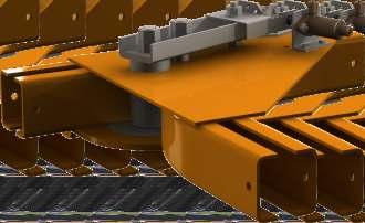
46 COUPLING BRIDGE CRANE In a monorail circuit a bridge crane can be mounted in order to allow the trolleys to run in parallel mounted tracks: e.g. in baking ovens or sorting areas. The bridge crane can be coupled mechanically or pneumatically.


47 SEMI AUTOMATED SYSTEMS 45 Railtechniek have developed several systems which can be applied according to the specific need like a simple powered conveying chain or a walking beam to provide automatic feed or automatic buffering. Our sales department can inform you about the many different standard solutions developed by Railtechniek for numerous applications.
48 46 TRANSFERS For automatization of manual monorail systems there are various options available. Transportation is done by use of a transfer, a chain with pusherdog running next to the monorail and pushing a loadbar. This is a cost efficient way for transportation through a spraybouth for example or the return line of empty carriers while keeping the rest of the system manual and not lose flexibility. Railtechniek standard Teleflex D8 transfers which can be used in near endless situations applies due to its modular components. Basic transfer example: (+230) A 5 261
49 TRANSFERS 47 Description Code Symbol Remark 1 Drive wheel 8T Type 1 = m/min Type 2 = m/min Type 3 = m/min 2 Turnwheel 8T In/out for 8T wheel right R 4 In/out for 8T wheel left L Double tension rail (+230) 6 Tension rail (+230) 7 Straight double track Straight track Bend 30 R Bend 45 R Bend 90 R Worm drive double track ask our engineering for motor specifications 13 Worm drive single track ask our engineering for motor specifications 14 Chain, till 80 C ZZ bearings 15 Chain, till 110 C RS bearings 16 Chain, till 280 C C3 bearings (open) 17 Lubrificator single track RT Lubrificator double track RT Pusherdog left RT Height A to be determined 20 Pusherdog right RT Height A to be determined Remark concerning the chain: pitch = mm Pusherdog can be mounted every mm


50 48 BRIDGE CRANES Railtechniek manufactures a large range of bridge cranes. Please ask for the separate catalogue


51 CABLE GUIDANCE 49 Railtechniek manufacturers a large range of tracks with adaptor brackets and clamps for cable guidance. Cable guidance applies for flat as well as for tubular flexible cable. Compressed air lines are hung on specially adapted trolleys. Please ask for the separate catalogue.


52 50 Cable Guidance Trolleys CABLE GUIDANCE Electric cable - Cable guidance trolley no for track no The cable guidance trolley no can be used in tracks no as well as in tracks no Ø27 Track Trolley No L W=75 Ø7 47 Track Trolley No L Ø7 H Cable Clamps W= Electric flat cable: clamp no max. cable width 40 mm M6 47 Compressed air line - Hose diameter minimum 10 mm maximum 18 mm - Hose diameter minimum 20 mm maximum 25 mm Clamp no Clamp no M6
53 CABLE GUIDANCE 51 The following table helps to determine the number of the cable guidance trolleys (n) and the length of the feed cable or the com-pressed air hose (LK) - For an effective runway of a trolley (Ln) < 30 m, the values of n and LK are detailed. Calculation B/2 Lv B/2 Ln Lw Lt Track length Ln Cable length Number of cable guidance trolley (n) for a loop height A (m) LK For an effective runway of the trolley (Ln) 30 m the values of n and LK are calculated as follows: -n= Ln x C 2 x A -1 n = number of cable guidance trolleys A: Loop height C: Coefficient Height of the loop (m): A Coefficient C LK = LT x m LT = Lw + Lv Lw = Ln + B Lv = n x w LK : Cable length LT : Total length of the track Lw : Length of the runway B : Width of the trolley Lv : Required space for the cable guidance trolleys w : Width of the cable guidance trolley


54 52 OUR DEVISIONS RAILTECHNIEK VAN HERWIJNEN B.V. TELEFLEX B.V. THE NETHERLANDS THE NETHERLANDS RAILTECHNIQUE FRANCE SARL TFX-RAILTECHNIK GmbH FRANCE GERMANY STEWART GILL CONVEYORS LTD. RAILTECHNIQUE SRL MOLDOVA ENGLAND MOLDOVA S P E C I A L I S T S I N O V E R H E A D C O N V E Y O R S

55 53


.")

56 Head office Engineering Fabrication Who is RAILTECHNIEK? Railtechniek van Herwijnen BV is an independent global company, specializing since their foundation in 1983 in the production and installation of Overhead Conveyors components and systems. The company designs, manufactures and installs only under international approved standards. For ancillary equipment such as electric switches, pneumatic, PLC's, bearings etc. we only use international suppliers who can meet with our standards. After the completion and sign off of the system by the customer a fully detailed manual inclusive of maintenance and operation instructions is supplied. After sales service & maintenance contracts are offered (subject to a separate contract). All PLC control systems use a modem connection with our 24-hour helpdesk. This is included as standard. Assembling Electrical steering department Service RAILTECHNIEK VAN HERWIJNEN B.V. Koelenhofstraat JR TIEL - THE NETHERLANDS PO Box HE TIEL - THE NETHERLANDS Telephone: +31 (0) Facsimilie: +31 (0) info@raitechniek.nl Internet: RAILTECHNIEK VAN HERWIJNEN B.V. RAILTECHNIQUE FRANCE S.A.R.L TFX-RAILTECHNIK GmbH RAILTECHNIQUE S.R.L MOLDOVA STEWART GILL CONVEYORS LTD. TELEFLEX B.V. DUNNEWOLT B.V.
Manual Monorail Track System
 www.wampfler.com Page 1/57 www.wampfler.com Page 2/57 1 General...6 1.1 Use of standard elements...7 1.2 Determination of the permissible support centers...9 1.3 Questionnaire...11 1.4 Project notes...12
Suspension tracks. Suspension tracks H 38. We put things in motion
 H 38 Our manual suspension tracks are also suitable for small and medium-sized trade companies. They are particularly distinguished by: Overhead conveyor system with Müsing spider assembly. Targeted material
JDN AIR CRANES AND CRANE KITS FOR EXPLOSION PROOF APPLICATIONS
 JDN AIR CRANES AND CRANE KITS FOR EXPLOSION PROOF APPLICATIONS CONTENT JDN AIR CRANES................................. 4 EXPLOSION PROOFNESS CLASSIFICATION AND MARKING........................ 4 ADVANTAGES
Edition 1 August Overhead Rail System. Models ZRAT, ZRA1, ZRA2 & ZRS2/3
 65985 Edition August 007 Overhead Rail System Models ZRAT, ZRA, ZRA & ZRS/ Table of Contents ZRAT Aluminum Rail & Components... Engineering Data for ZRAT Aluminum Rail... How to Order ZRAT Aluminum Runway
Cable Trolleys for C-Rails Program
 Cable Trolleys for C-Rails Program 02 0 0260 Contents C-Rail and Accessories Program 02 C-Rail x... 4 Track Coupler... 4 End Stops... 4 Track Support Brackets... 4 Support Arm and Girder Clip... Brackets...
2. Runway & Crane System
 2. Runway & Crane System The crane runway girders, crane, columns and building frames can all be regarded as components of the overall crane installation. The individual components cannot be designed in
CRANE SET BRIDGE CRANE COMPONENTS
 CRANE SET BRIDGE CRANE COMPONENTS TO CREATE YOUR CUSTOM BRIDGE CRANE A series of products conceived and designed to be assembled and create a bridge crane suited to your needs STANDING BRIDGES 1 2 4 5
HOFFMANN Fördertechnik GmbH Wurzen
 HOFFMA Fördertechnik GmbH Wurzen Innovative electric chain hoists Milestones on the way to success 95 954 955 956 The initial LIFTKET design has introduced the change to low headroom hoists by placing
Technical data/component parts
 Technical data/component parts Demag pillar and wall-mounted slewing jib cranes 191214 en GB 203 814 44 714 IS 132 Manufacturer Terex MHPS GmbH Forststrasse 16 40597 Düsseldorf, Germany www.demagcranes.com
Drum Handling. Drum Transporter and Pouring Stand. Drum Trolley and Pouring Stand. Low Loading Drum Carrier Capacity 250kg.
 62 Drum Transporter and Pouring Stand For 210 litre steel drums Capacity 350kg Welded steel construction. Removable 2-position handle Wheels: 2 x 400 mm dia. 2 x 160mm dia. castors, with solid rubber tyres.
Technical data Demag DC-Com 1 to DC-Com 10 chain hoist
 Technical data Demag DC-Com 1 to DC-Com 10 chain hoist 42647546.jpg 090506 EN 203 571 44 714 IS 817 Design overview Single-fall design 1 2 4 3 6 5 7 8 9 14 16 15 13 1 Electrical equipment cover 2 Brake
Technical data Demag chain hoist DC-Pro 1, DC-Pro 2, DC-Pro 5, DC-Pro 10, DC-Pro 20 Demag Manulift chain hoist DCM-Pro 1, DCM-Pro 2, DCM-Pro 5
 Technical data Demag chain hoist 1,,, 1, Demag Manulift chain hoist DM-Pro 1, DM-Pro, DM-Pro 46474.eps 1 EN 3 44 714 IS 817 Design overview Single-fall design 1 4 3 6 7 8 9 14 16 1 13 1 Electrical equipment
ELECTRIC CHAIN HOISTS. HOFFMANN Fördertechnik GmbH Wurzen
 ELECTRIC CHAIN HOISTS HOFFMANN Fördertechnik GmbH Wurzen Innovative electric chain hoists Milestones on the way to success 1952 1954 1955 1956 1966 The new generation: starting from 125 kg The initial
Materials handling technology: One of four strong product divisions!
 Product divisions H 1 TORWEGGE Materials Handling Technology: Energy supplies for power and compressed air Spring cable reels Box type conductor rails C-rail program with wall- or column-mounted swivel
ENGLISH. Electric wire rope hoists. Crane components. Controlling/Monitoring
 ENGLISH Electric wire rope hoists Crane components Controlling/Monitoring 04 12 18 30 Controlling/ Monitoring CRABster Winch CraneKit Crane components End carriages BLOCKster Travelling machineries NovaMaster
300 SERIES STANDARD DUTY CURVED TRACK
 300 SERIES STANDARD DUTY CURVED TRACK COMPLETE TRACK MODEL NUMBERS 301A 301W 316A 316W 328A 328W 300B SERIES BLACK CURVED TRACK COMPLETE TRACK MODEL NUMBERS 301AB 301WB 316AB 316WB 328AB 328WB SINGLE CARRIER
4 pole insulated conductor rails UNILIFT-ULA 35A, 50A, 80A, 100A
 2 Table of contents General information... 4 Elements of the conductor rail supply line... 4 Innovative connection method... 5 Technical properties... 6 Construction of the line section... 6 Line section...
Product Line Glossary Terms
 PURPOSE This document defines terminology used across all of Harrington s Product Lines. SCOPE These definitions will include the following Product Lines: Manual Electric Air Wire Rope Cranes BACKGROUND
Hoists & Winches. :: Electric Chain Hoists 26 :: Manual Hoists 30 :: Pneumatic Hoists 31 :: Winches 32 :: Beam Trolleys 34
 Hoists & Winches Lifting & Handling Equipment :: Electric Chain Hoists 26 :: Manual Hoists 30 :: Pneumatic Hoists 31 :: Winches 32 :: Beam Trolleys 34 Electric Chain Hoists Compact Electric Chain Hoists
Cable Carriers. Information about further items of our product range is available on request:
 Cable Carriers Information about further items of our product range is available on request: Copper head rails Current collectors Insulators Plastic- and neoprene-cables Junction boxes Cable reels Radio
Dearborn Overhead Crane
 A Class Above... In Productivity. In Safety. In Ease of Positioning and Movement. In Ease of Installation. In Designs, Capacities, and Spans. It s no wonder more and more businesses like yours are choosing
HITACHI ELECTRIC CHAIN HOISTS
 HITACHI ELECTRIC CHAIN HOISTS Hitachi s reputation for excellence in design, quality, reliability and performance has made this brand a global market leader. With over three decades of proven reliability
Jib cranes: mounted on a wall or on a column, with total or partial rotation capability, manual or motorized.
 Jib cranes: mounted on a wall or on a column, with total or partial rotation capability, manual or motorized. 2, boulevard de l Industrie - B.P. 20059-28509 Vernouillet cedex - France Telephone: (33) 02
Energy Supply Systems
 Energy Supply Systems SINGLE POLE INSULATED CONDUCTOR RAIL 815 100 amps KAT0815-0001b-E Conductor rail system in a high bay storage Slip ring with conductor rail system in a stretch-foil packing machine
Tailor-made modular crane systems for Safe Working Loads up to 2000 kg. HB-System
 Tailor-made modular crane systems for Safe Working Loads up to 2000 kg HB-System The ABUS HB-System in practice A versatile workhorse 2 3 Crane solutions from a single source the crane system The HB-System
MANUAL HOISTING TAKE THE WEIGHT OUT OF HEAVY DUTY LIFTING
 MANUAL HOISTING TAKE THE WEIGHT OUT OF HEAVY DUTY LIFTING CARE & SAFETY INSTRUCTIONS 114 CX & M3 SERIES CHAIN BLOCKS 115-117 C SERIES CHAIN BLOCKS 118 MINI II CHAIN BLOCKS 118 LX & L5 SERIES CHAIN BLOCKS
ENGLISH. Light Cranes. Chain Hoists
 ENGLISH Light Cranes Chain Hoists 04 12 18 24 28 JIBster Slewing cranes ProfileMaster, Lightweight crane system LIGHTster, Lightweight crane system SK Electric chain hoists CRAFTster Hand chain blocks
WORK STATION BRIDGE CRANES
 FREE STANDING WORK STATION BRIDGE CRANES CAPACITIES: SPANS: ENCLOSED TRACKS: PRODUCTIVITY: Up to 4000 lbs Up to 30' Steel, Aluminum & Stainless Steel Average 28% Increase A Class Above... In Productivity.
Pillar and wall-mounted slewing jibs and cranes. Workplace efficiency improvement with the Demag crane range
 Pillar and wall-mounted slewing jibs and cranes Workplace efficiency improvement with the Demag crane range System components and installations As a pioneer in overhead materials handling, Demag Cranes
Interlocks 325 Series
 rd 12070 43 St. NE, St. Michael, MN 55376 763-497-7000 www.tcamerican.com sales@tcamerican.com Installation Instructions Interlocks 325 Series 3I-615; 3I-430 3I-613; 3I-450 Crane Interlock and Operating
Festoon systems. Flatform cable festoon systems. Introduction. Flexible with energy!
 Festoon systems Flexible with energy! Introduction Flatform cable festoon systems The AKAPP flatform cable festoon systems provide a safe, effective and economical means of supplying power to cranes, hoists
PO W ERCO N H A N D LIN G SYST EM S (PT Y) LT D.
 LT D.") POWERCON CR MONORAIL SYSTEM GUIDE About us: POWERCON HANDLING SYSTEMS specialises in complete overhead monorail conveyors as well as complete Turnkey Operation and Factory Automation projects. Established
POWERCON CR MONORAIL SYSTEM GUIDE About us: POWERCON HANDLING SYSTEMS specialises in complete overhead monorail conveyors as well as complete Turnkey Operation and Factory Automation projects. Established
EXPLOSION-PROOF ELECTRIC WIRE ROPE HOIST BWX
 The BWX electric wire rope hoists are the best as versatility and features, matching requirements of hazardous area. One single lifting speed or two lifting speeds are got with the application of inverter
RH Electric Wire Rope Hoists
 RH Electric Wire Rope Hoists Harrington RH wire rope hoists are designed and built for today s heavy-duty wire rope hoist applications including fabricating, die handling, paper mill and production line
HELM Circular and Power & Free Conveyors. Conveyor Technology
 HELM Circular and Power & Free Conveyors Conveyor Technology Group 50 Circular and Power & Free Conveyors Circular and Power & Free Conveyors Page 3 Delivery Program Combination/Shingle Conveyor/Basement
Fall Protection. Eliminate Bounce Effect and Secondary Falls. Modular Ergonomic Smooth Running Versatile.
 4 Fall Protection Eliminate Bounce Effect and Secondary Falls Modular Ergonomic Smooth Running Versatile www.nikotrack.com Contents 1. General Instructions Manufacturer Distribution 1.1. Purpose 2. Safety
GIS-CH ELECTRIC CHAIN HOIST: SIMPLE, RELIABLE, SECURE.
 GIS-CH ELECTRIC CHAIN HOIST: SIMPLE, RELIABLE, SECURE. GIS YOUR GENERAL CONTRACTING PARTNER FOR EFFICIENT MATERIAL FLOW. Complete range of market services for off-floor goods handling A wealth of know-how
ENGLISH. Light Cranes. Chain Hoists
 ENGLISH Light ranes hain Hoists 04 12 22 Light ranes LIGHTster ProfileMaster Electric chain hoists HINster HINsterGT Hand chain blocks RFTster 03 03 Look ahead! ontent SWF is one of the leading global
Interlocks 200 Series
 rd 12070 43 St. NE, St. Michael, MN 55376 763-497-7000 www.tcamerican.com sales@tcamerican.com Installation Instructions Interlocks 200 Series 2I-515; 2I-930 2I-513; 2I-850 Crane Interlock and Operating
DIVISION 14 CONVEYING EQUIPMENT
 DIVISION 14 CONVEYING EQUIPMENT Page 1 of 4 Part 1 General 1.1 SCOPE OF WORK.1 Supply and install one (1) complete overhead (push trolley electric chain hoist) under running monorail crane systems as mentioned
HOUR DESPATCH. double sided
 56 Wall Racks Wall Storage 2 or 3 cylinder units for 2 cylinder sizes. These racks must be fixed to the wall at a height of at least two-thirds of cylinder height. Supplied with pre-drilled fixing holes.
Under Running, Single Girder Overhead Cranes
 TOTAL CRANE SYSTEMS MANUFACTURERS OF OVERHEAD CRANES AND HOISTS Under Running, Single Girder Overhead Cranes Engineering & Design Data TOTAL CRANE SYSTEMS Crane Reference Diagram All data may be referenced
Trolleys and beam clamps
 32 Trolleys and beam clamps Trolleys and beam clamps Yale trolleys and beam clamps can be supplied in many different designs and are used to support and mount hoisting equipment for fixed or traversing
GENERAL INDEX TR60. 6 YELLOW LINE Continuous Conductors. Max 5 Poles. 8 BLUE LINE Pre-Mounted Conductors TR85H5P. YELLOW LINE Continuous Conductors
 2 Automation - Lift - Handling System GENERAL INDEX 2 DESCRIPTION 3 BUSBAR LINE VERSIONS LINE TYPE / AMPERAGE COVERAGE 5 TR60 40 A 50 A 60 A 70 A 100 A 140 A 160 A 200 A 320 A 6 YELLOW LINE Continuous
Crane. Bridge. Crane Control. Crane. Force, breakaway. hook device. hook device. Friction-type pressure gripping lifters. Below. hook device.
 Fail-safe General A provision designed to automatically stop or safely Control any motion in which a malfunction occurs. (CMAA Spec. 70) Field wiring General The wiring required after erection of the crane.
ALUMINIUM TRACKS SYSTEM.
 ALUMINIUM TRACKS SYSTEM www.utechinter.com www.facebook.com/utechinter CONTENTS Page General 3 UTA Aluminium Track System 4 Single girder suspension crane 4 Double girder suspension crane 5 Diagram for
ELECTRIC HOIST & CRANES
 ELECTRIC HOIST & CRANES Electric Wire Rope Hoists and Cranes JL LOW HEADROOM HOIST (4/1 Rope Reeving) JL FOOT-MOUNTED HOIST (4/2 Rope Reeving) CD1/MD1 UNDER-SLUNG HOIST (2/1 Rope Reeving) JL STANDARD SINGLE
MOTIV-8 FLEXIBLE CABLE SYSTEMS
 MOTIV-8 FLEXIBLE CABLE SYSTEMS www.conductix.com.au CONDUCTIX FLEXIBLE CABLE SYSTEMS Designed and manufactured in Australia. Proven in applications throughout the world for over 25 years. Full range of
Blocks. your reliable partner
 Blocks your reliable partner Dear Customer, For over 90 years the production of high tensile shackles has been our core business and competence. The designs and quality standards of our wire rope- and
Electric chain hoist PLANETA-GCH. Simple Reliable Safe. Geared limit switch. Lifting heights up to 220 m Accuracy for repetition assured.
 Electric chain hoist PLANETA-GCH Simple Reliable Safe Compact design Robust construction Simple maintenance Fast availability Modern technology Chain guidance 2-part construction to optimize maintenance
Before equipment use, please read this operation manual carefully. Serial Number: Date Purchased:
 Pushed & Geared Trolleys OPERATION MANUAL This operation manual is intended as an instruction manual for trained personnel who are in charge of installation, maintenance, repair etc. Before equipment use,
Instructions for Use Plain Trolley ULK Geared Trolley UHK
 Instructions for Use Plain Trolley Geared Trolley Item no. Load-carrying capacity (payload) Weight Trolley widths *special trolley widths* Device dimensions mm H / W / D Minimum curve radius mm -005 0,5
Energy Supply Systems
 Energy Supply Systems MULTIPOLE CONDUCTOR RAIL 831 10-125 amps KAT0831-0001b-E 13 pole multipole conductor rail in 33 package distribution centres of the postal service (Post AG) 9 pole multipole conductor
Conveyors 12. slide strips roller Conveyors roller elements Conveyor rollers Chain Transfer
 Conveyors slide strips roller Conveyors roller elements Conveyor rollers Chain Transfer Application example conveyors Transport solutions and goods provision 1 2 3 4 5 6 7 8 362 9 1 slide strips Low-wear
Narrow Aisle Drum Truck. Drum Handling. Three-in-one Drum Carrier. Drum Transporter and Pouring Stand. Drum Handling. Capacity 300kg UDL
 41 Narrow Aisle Drum Truck Capacity 300kg UDL For transport and dispensing from 210ltr steel or plastic drums. Overall width of truck is less than a standard 210 ltr drum Use as truck for transporting
End Trucks 325 Series
 Installation Instructions End Trucks 325 Series These instructions are for 325 Series End Trucks, as used on 325 Series Patented Track rail. See the Index to locate the appropriate pages for the model
ROLL-UP COVERS Standard products
 A ROLL-UP COVERS Standard products P.E.I. Roll-up Covers are normally equipped with our patented system of multiple springs. This offers countless advantages: Reliability Compact size Extremely high speeds
S4 WIRE ROPE HOISTS EXPERIENCE THE DIFFERENCE
 www.morriscranes.co.uk S4 WIRE ROPE HOISTS EXPERIENCE THE DIFFERENCE S4 WIRE ROPE HOISTS Range Whichever way you look at the Morris S4 it's versatility, ease of use and reduced cost of ownership shines
Multipole Conductor Rail MultiLine Program 0831
 Multipole Conductor Rail MultiLine Program 0831 Contents Description / Technical Data Description....2 Technical Data....3 Conductor Rails Rails complete with pre-mounted Connector...4 Power Feeds....5
Energy and data transmission
 product description Line 30 41 41 stainless steel Festoonsystem line30 41 and 41 inox Giovenzana The festoon system is the traditional system for energy transmission for various type of handling equipment.one
CEILING MOUNTED WORK STATION STEEL BRIDGE CRANE
 SECTION 14636 CEILING MOUNTED WORK STATION STEEL BRIDGE CRANE ***** Gorbel, Inc. manufactures a broad range of material handling cranes including monorail, bridge, gantry, and jib cranes. Numerous work
catalogue Endless handling solutions CATALOGUE EDITION AU 04 AUTOMOTIVE MATERIALS HANDLINGS DRIVE AND DRIVEN ROLLERS
 au Endless handling catalogue solutions CATALOGUE EDITION AU 04 AUTOMOTIVE MATERIALS HANDLINGS DRIVE AND DRIVEN ROLLERS INDEX DUGOMRULLI HISTORY 3 PRODUCT RANGE 5 AUTOMOTIVE ROLLER SOLUTIONS 7 COATED PALLET
WIRE ROPE HOISTS & TROLLEYS. XM Series MISIA HOISTS & LIFTING SOLUTIONS
 WIRE ROPE HOISTS & TROLLEYS XM Series MISIA HOISTS & LIFTING SOLUTIONS INDEX MISIA THE COMPANY 2 QUALITY AND CERTIFICATIONS 4 MISIA WIRE ROPE HOISTS XM SERIES 6 Standard configurations 8 Components 10
KT 2000 Small Crane Technology_
 STAHL CraneSystems Lifting technology Drive technology Control technology KT 2000 Small Crane Technology_ optimised for every application KT 2000 Small Crane Technology from STAHL CraneSystems Experienced
Electric Chain Hoists. CLF & CLW Series. The New CLF Series: Reliable, safe, convenient, efficient and compact size
 Industrial Cranes Customized Cranes Light Crane Systems Crane Components Electric Wire Rope Hoists Electric Chain Hoists Spare Parts Electric Chain Hoists CLF & CLW Series The New CLF Series: Reliable,
C-Rail Festoon track systems
 C-Rail Festoon track systems & Hose carrying systems Application C-Rail festoon track systems are the ideal solution for carrying cables supplying power to many types of moving machinery using either flat
KBK 100, I, II-L, II, III crane construction kit Project drafting and components Design principles, selection criteria, components
 KBK 100, I, II-L, II, III crane construction kit Project drafting and components Design principles, selection criteria, components 310505 EN 202 976 44 714 IS 152 Manufacturer: Demag Cranes & Components
Compressed Air and Electric Supply System Program C40
 Compressed Air and Electric Supply System Program C40 Table of Contents Overview 4 Product Description...4 System Overview....4 Rail Components 5 General Information...5 Load Diagram....5 Rail Couplers....6
Owner s Manual. ELECTRIC WIRE ROPE HOIST and TROLLEY RH SERIES
 EFFECTIVE: September 25, 2007 Owner s Manual ELECTRIC WIRE ROPE HOIST and TROLLEY RH SERIES 2 Ton through 20 Ton Capacity Product Code and Serial Number WARNING This equipment should not be installed,
ETA-5 RAIL SYSTEMS. , Unified Industries, Inc. All Rights Reserved.
 RAIL SYSTEMS PAGE 1 TABLE OF CONTENTS PAGE Rail Profiles...2-4 Rail Load Charts...5-6 ETA-4 & Hangers...7-10 Inspection Gate...11 ETA-4 & Load Trolleys...12-15 ETA-4 & Festoon Trolley...16-19 ETA-4 &
Product Overview Festoon-Systems for I-Beams
 Product Overview Festoon-Systems for I-Beams 2 Conductix-Wampfler Festoon-Systems Count on it! On the go! Cable trolley system program 0350 on a steel mill overhead bridge crane We move your business:
Cable Carriers. Information about further items of our product range is available on request:
 Cable Carriers Information about further items of our product range is available on request: Copper head rails Current collectors Insulators Plastic- and neoprene-cables Junction boxes Cable reels Radio
technical sheet RAILSCAF horizontal monorail access system
 Railscaf horizontal monorail access system ref.: T-529 rev. no.: 2 date: 0/98 page: /8. GENERAL The is a building maintenance system comprising a monorail fixed around the perimeter of a building or structure.
ACI Hoist & Crane. Festoon System. 689 S.W. 7th Terrace Dania, FL (954) Fax (954) Toll Free A-HOIST ( )
 Fax (954) Toll Free A-HOIST ( )") ACI Hoist & Crane Festoon System 689 S.W. 7th Terrace Dania, FL 33004 (954) 921-1171 Fax (954) 921-7117 Toll Free 1-888-4-A-HOIST (1-888-424-6478) www.acihoist.com 2 Standard Duty C-Track Index 1. General
ACI Hoist & Crane Festoon System 689 S.W. 7th Terrace Dania, FL 33004 (954) 921-1171 Fax (954) 921-7117 Toll Free 1-888-4-A-HOIST (1-888-424-6478) www.acihoist.com 2 Standard Duty C-Track Index 1. General
Lyftman LR-Systems. Lyftman
 Lyftman LR-Systems Lyftman Lyftman LR-Systems Produced from cold rolled, single piece high strength steel: The result is the reliable and cost effective LR120/170 profile. Self-adjusting joint concept:
THE BEST MOVES IN THE WORLD
 THE BEST MOVES IN THE WORLD UNDERHUNG & TOP RUNNING CRANES STACKER CRANE SYSTEMS MONORAILS `SPECIALIZED AVIATION MAINTENANCE CRANES SPECIALIZED LAUNDRY & OVERHEAD MATERIALS HANDLING THE RIGHT MOVE TC/American
Demag DBS Air Balancers For handling loads with ease, precision and safety
 Demag DBS Air Balancers For handling loads with ease, precision and safety 38539 Highly precise, simple and safe Significant properties With the Demag Air Balancer, you can: Precisely and smoothly position,
WORK STATION BRIDGE CRANES & MONORAILS FREE STANDING & CEILING MOUNTED CAPACITIES FROM 250 TO 4000 LBS
 WORK STATION BRIDGE CRANES & MONORAILS FREE STANDING & CEILING MOUNTED CAPACITIES FROM 250 TO 4000 LBS PRE-ENGINEERED COMPONENTS LodeRail is a complete crane system. The wide variety of components makes
STEMMANN-TECHNIK Cable Trolley, KW80
 STEMMANN-TECHNIK Cable Trolley, KW80 Our KW80 cable trolley system for i-beam mountings is designed to transport flat and round cables as well as hose packages. Thanks to the modular design, the KW80 system
Provincial Doors Inc.
 Architectural Specifications* HI-PRESSURE DOOR Provincial Doors Inc. 3057 Kingsway Rd. Sudbury, ON P3B 2G5 (705) 560-8755 (800) 641-7893 (705) 524-1303 (FAX) * Please verify specifications. Provincial
Product overview. Phone Fax
 Product overview Arneburger Str. 37n 39590 Tangermünde Germany tangermuende@minda.de Phone +49 39322 996-0 Fax +49 39322 996-66 MINDA Tangermünde Your expert for complex solutions For more than two decades,
ERGONOMIC WORK STATION CRANES
 Free Standing Work Station Bridge Cranes Ceiling Mounted Work Station Bridge Cranes Aluminum Work Station Bridge Cranes ERGONOMIC WORK STATION CRANES Work Station Jib Cranes I-Beam Jib Cranes Articulating
INDUSTRY CUSTOM STAGE. liftket.de
 INDUSTRY CUSTOM STAGE LIFTKET - HISTORY WITH A FUTURE Much has changed since the company was founded in 1948. One thing, however, has always remained the same: The quality of LIFTKET products - Made in
CEILING MOUNTED WORK STATION BRIDGE CRANES & MONORAILS
 CEILING MOUNTED WORK STATION BRIDGE CRANES & MONORAILS CAPACITIES: SPANS: ENCLOSED TRACKS: PRODUCTIVITY: Up to lbs Up to 0', Aluminum & Stainless Average 28% increase A Class Above... In Productivity.
Trolleys. 200 Series. These instructions are for plain or idler trolleys as used on TC/American Monorail 200 Series Patented Track rail.
 Installation Instructions Trolleys 200 Series These instructions are for plain or idler trolleys as used on 200 Series Patented Track rail. DANGER Lifting Operations Installation of equipment such as s
Index. Purchase guide. Belt conveyor. Elevator Belt conveyor. Modular belt conveyor. Stainless steel belt & slat chain conveyor. Accessories & options
 belts SOMEFI is a company dedicated to the manufacture and sale of conveyors and modular handling equipment. For more than 40 years SOMEFI has offered a complete range of industrial conveyors, of flexible
SPACEMASTER WIRE ROPE HOISTS
 SPACEMASTER WIRE ROPE HOISTS The Spacemaster SX represents an innovative design that includes a large drum diameter giving Spacemaster SX hoists the lowest headroom and best wheel loads in the industry
Die changing technique
 Die changing Die changing 8 Contents Product group 8 Roller bar, hydraulically lifted for heavy loads (400 bar), lifting of the complete roller bar for medium loads (120 bar), lifting of individual rollers
CRL-1 / CRL-2 CABLE FESTOON SYSTEM Set up of a C-Rail System REQUIRED COMPONENTS
 CRL-1 / CRL-2 CABLE FESTOON SYSTEM Set up of a C-Rail System Based on the different cable trolley versions and numerous components you can compile your individual C-rail system. In addition to straight
CRANE TESTING REQUIREMENTS FOR PERFORMANCE TESTS
 APPENDIX I CRANE TESTING REQUIREMENTS FOR PERFORMANCE TESTS 1. PERFORMANCE TESTING. a. Performance testing includes both operational performance testing and load performance testing. The following tables
4 pole insulated conductor rails ULA 35A, 50A, 80A, 100A
 Table of contents General information... 3 Elements of the conductor rail supply line... 3 Innovative connection method... 3 Technical properties... Construction of the line section... Line section...
HSpecialties Inc. TABLE OF CONTENTS
 TABLE OF CONTENTS Introduction... Curtain Track Selection Guide...2 Ordering COMPLETE Tracks...3 00 Series Standard-Duty Straight Track...4 200 Series Black Medium-Duty Straight Track...8 300 Series Standard-Duty
SERVICE MACHINE TOOL SERVICE LIGHT LIFTING INDUSTRIAL CRANES PROCESS CRANES PORT CRANES LIFT TRUCKS YARD IT XM LIGHT CRANE SYSTEMS
 SERVICE MACHINE TOOL SERVICE LIGHT LIFTING INDUSTRIAL PROCESS PORT LIFT TRUCKS YARD IT XM LIGHT CRANE SYSTEMS Konecranes Konecranes VERSATILE SOLUTIONS XMM monorail solutions up to 2 ton load. XM Light
RIG-I-FLEX 140 SERIES CURTAIN TRACKS
 RIG-I-FLEX 140 SERIES CURTAIN TRACKS Parts Included 140 RIG-I-FLEX CWANA code CORD OPERATED/MOTORIZED WALK-ALONG 140 (240) 140-R (240-R) 141 (241) 141-R (241-R) 142 (242) 142-R (242-R) STRAIGHT CURVED
Performa Mesh Trays. Flexible solution for the routing of cables
 Flexible solution for the routing of cables Solutions for each application Performa is one of the most flexible solutions on the market for the routing of cables in light duty and medium duty installations.
Underfloor Wheel Lathe Type U CNC-controlled machine with automatic measuring system
 Underfloor Wheel Lathe Type U 2000-150 CNC-controlled machine with automatic measuring system...technology in motion Operative range and scope of application The modern underfloor wheel lathe does not
SPACEMASTER WIRE ROPE HOISTS
 SPACEMASTER WIRE ROPE HOISTS The Spacemaster SX represents an innovative design that includes a large drum diameter giving Spacemaster SX hoists the lowest headroom and best wheel loads in the industry
Pneumatic chain hoists
 Depicted chain container optionally available. Available in explosion proof version. Pneumatic chain hoist model CPA Capacity 125-980 are characterized by high durability in a great number of industrial
76,6 m 40,9 m. 16,5 t. 70,0 m 3,9 t ( 4,0 t) 2,0 m. 50,0 m 6,9 t ( 7,0 t) 40,0 m 9,2 t ( 8,3 t)
 2,0 m. 50,0 m 6,9 t ( 7,0 t) 40,0 m 9,2 t ( 8,3 t)") 1 Schedule drawing 1.1 Schedule drawing 21,2 m 76,6 m 40,9 m 1,0 m 2,5 m 18,7 m 1,1 m 2,6 m 4,0 m 19,2 m - 24,6 m 16,5 t 1,9 m 7,7 m 75,0 m 3,2 t ( 3,3 t) 70,0 m 3,9 t ( 4,0 t) 2,0 m 60,0 m 5,2 t ( 5,3
1 Schedule drawing 1.1 Schedule drawing 21,2 m 76,6 m 40,9 m 1,0 m 2,5 m 18,7 m 1,1 m 2,6 m 4,0 m 19,2 m - 24,6 m 16,5 t 1,9 m 7,7 m 75,0 m 3,2 t ( 3,3 t) 70,0 m 3,9 t ( 4,0 t) 2,0 m 60,0 m 5,2 t ( 5,3
Pillar and wall-mounted slewing jibs and cranes. Workplace efficiency improvement with the Demag crane range
 Pillar and wall-mounted slewing jibs and cranes Workplace efficiency improvement with the Demag crane range System components and installations As a pioneer in overhead materials handling, we have been