Chapter 1 Aircraft Electrical System
|
|
|
- Meghan Sanders
- 5 years ago
- Views:
Transcription
1 Chapter 1 Aircraft Electrical System
2 Chapter 1 Aircraft Electrical system Electrical component Storage Battery DC & AC Generator Control and Protection in DC Electrical System Electrical Machine and control Lighting
3 When, Why Electric Energy was used in an aircraft?
4 Electrical energy is being widely used Clean form of energy absence of smoke, ashes, dust, etc. Easily convertible to light, heat, mechanical, chemical energy etc. Easily and economically transportable by means of running cables.


5
6 Electrical systems have been an onboard fixture since the Wright Flyer. In those days the role of electricity was limited to the magneto which provides sufficient voltage to spark the fuel/air mixture.
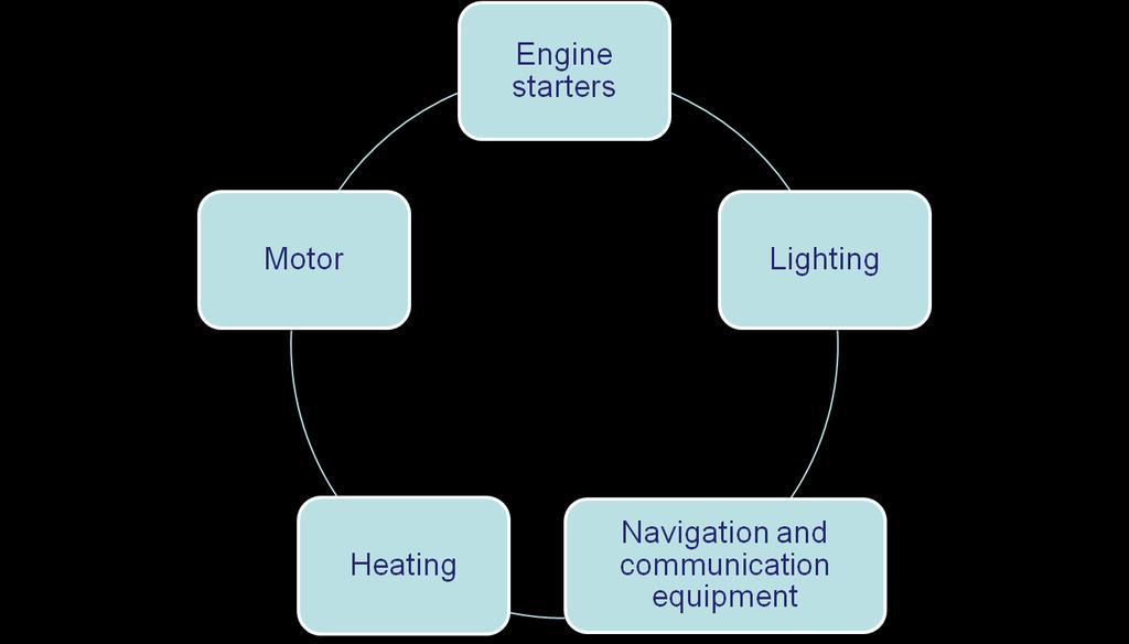
7 Magnetos still supplied the spark to the engines, but 14- or 28-volt direct-current generator supplied current to operate the navigation and landing lights, the radios. Generators kept the batteries charged to operate the electric motor used to start the engines.
8
9 The years between the two world wars is the golden age of aviation, improved in importance and complexity. As the twentieth century ended, electrical systems have become just about equal in importance with the engines.
10 For many years, light planes exclusively used the 14-volt electrical system. Starting approximately in the early 1980s, the 28- volt system began to take over light aircraft. The primary purpose of igniting the fuel/air mixture is still the domain of the magneto. However, the demand for electrical energy in the airplane has increased tremendously.
11 Jet airliners have extremely complex electrical systems and use alternating current as the primary source of electricity. Batteries are used for emergency and backup operations and for some special applications.
12 DEFINITIONS OF AIRCRAFT ELECTRICAL SYSTEM
13 Electrical System An electrical system consists of an electrical power source, its power distribution system and the electrical load connected to that system.
14 A typical aircraft electrical system consists of a primary (main) power source, emergency power source, secondary power conversion equipment, system control and protection devices, interconnection network, and power distribution system.
15 Electrical Source The electrical equipment which produces, converts or transforms electrical power.
16 Electrical Source Some common AC sources are identified as follows: AC alternators inverters transformers frequency changers.
17 Electrical Source Some common DC sources are DC generators converters batteries.
")


18 Primary (Main) Power Source
19 Primary Power Source A primary source is equipment that generates electrical power from energy other than electrical, and is independent of any other electrical source.


20 Secondary Source A secondary source is equipment that transforms and/or converts primary source power to supply electrical power to either AC or DC powered equipment.
21 Secondary source. A secondary source is equipment that transforms and/or converts primary source power to supply electrical power to either AC or DC powered equipment. A secondary source is entirely dependent upon the primary source and is considered part of the load of the primary source.


22 Emergency Power Source
23 Emergency power In the event of a primary power source failure, emergency power is usually provided from independent auxiliary power unit (APU)-driven generator(s), ram air or hydraulically-driven generator(s), or batteries.


24 Ground power
25 ground power source A ground power source can be connected to the bus bar distribution system thus allowing all electrical systems to be powered independently of aircraft battery or generating systems. The source can be either a motorised generating unit or a battery unit.
26 Nominal rating This rating is usually a continuous duty rating for specified operating conditions.
27 Condition of Power Sources Normal electrical power operation Abnormal electrical power operation Emergency electrical power operation
28 Normal electrical power operation Normal operating conditions assumes that all of the available electrical power system is functioning correctly within Master Minimum Equipment List (MMEL) limitations (e.g. AC and/or DC Generators, Transformer Rectifier Units, Inverters, Main Batteries, APU etc.).
29 Abnormal electrical power operation Abnormal operation occurs when a malfunction or failure in the electric system has taken place and the protective devices of the system are operating to remove the malfunction or the failure from the remainder of the system before the limits of abnormal operation are exceeded.
30 Emergency electrical power operation Emergency operation is a condition that occurs following a loss of all normal electrical generating power sources or other malfunction that results in operation on standby power (batteries and or other emergency generating source such as an APU or Ram Air Turbine (RAT) only.
31 Classification of electrical load Vital (critical, emergency) Essential Non-essential
32
33 Typical Aircraft Electrical System Primary (main) power source Emergency power source Secondary power conversion equipment System control and protection devices Interconnection network Power distribution system

34
35 As a engineer, we should know the following information electrical system operation, which describes primary and secondary power sources, bus configuration with circuit breakers and connected loads for each bus. A copy of the bus wiring diagram or electrical schematic should also be considered for inclusion in the report.
36 As a engineer, we should know the following information alternators and other power source description and related data (including such items as battery discharge curves, Transformer Rectifier Unit (TRU), Inverter, APU, RAT, etc.)
37 List of Electrical Data
38 END OF CHAPTER 1
An advisory circular may also include technical information that is relevant to the rule standards or requirements.
 Revision 0 Electrical Load Analysis 2 August 2016 General Civil Aviation Authority advisory circulars contain guidance and information about standards, practices, and procedures that the Director has found
E230 Aircraft Systems
 E230 Aircraft Systems Blackout 6th Presentation School Of Engineering Function of Aircraft Electrical System To generate, regulate and distribute electrical power throughout the aircraft Systems that requires
B777. Electrical DO NOT USE FOR FLIGHT
 B777 Electrical DO NOT USE FOR FLIGHT 6.10 Electrical-Controls and Indicators Electrical Panel [IFE/PASS SEATS and CABIN/UTILITY switches basic with C/L 350] 1 2 IFE/PASS CABIN/ SEATS UTILITY 3 11 APU
AIRCRAFT GENERAL KNOWLEDGE (1) AIRFRAME/SYSTEMS/POWERPLANT
 AIRFRAME/SYSTEMS/POWERPLANT") 1 In flight, a cantilever wing of an airplane containing fuel undergoes vertical loads which produce a bending moment: A highest at the wing root B equal to the zero -fuel weight multiplied by the span
1 In flight, a cantilever wing of an airplane containing fuel undergoes vertical loads which produce a bending moment: A highest at the wing root B equal to the zero -fuel weight multiplied by the span
This chapter contains information on DC Generation, External Power, and Electrical Load Distribution.
 CIRRUS AIRPLANE MAINTENANCE MANUAL Electrical Power CHAPTER 24-00: ELECTRICAL POWER GENERAL 24-00: ELECTRICAL POWER 1. General This chapter contains information on DC Generation, External Power, and Electrical
Electrical System B-17 Technical Session for Flight Engineers
 Electrical System B-17 Technical Session for Flight Engineers 7/12/2017 GULF COAST WING---COMMEMORATIVE AIR FORCE Boeing B17 N7227C (Texas Raiders - TR) Prepared by Jim Hower The intent of this guide is
SAFRAN OVERVIEW 8% OF SALES INVESTED IN R&D. $18.5 BILLION IN SALES generated in 2017 (1) #1 WORLDWIDE AEROSPACE: PROPULSION SYSTEMS
 #1 WORLDWIDE AEROSPACE: PROPULSION SYSTEMS") HOW BUSINESS FLIES SAFRAN OVERVIEW PROPULSION Safran Aircraft Engines Safran Nacelles CTRICAL ELECTRICAL POWER Safran Transmission Systems Safran Electrical & Power Safran Power Units Safran Landing Systems
HOW BUSINESS FLIES SAFRAN OVERVIEW PROPULSION Safran Aircraft Engines Safran Nacelles CTRICAL ELECTRICAL POWER Safran Transmission Systems Safran Electrical & Power Safran Power Units Safran Landing Systems
SAFRAN OVERVIEW 8% OF SALES INVESTED IN R&D. $18.5 BILLION IN SALES generated in 2017 (1) #1 WORLDWIDE AEROSPACE: PROPULSION SYSTEMS
 #1 WORLDWIDE AEROSPACE: PROPULSION SYSTEMS") HOW BUSINESS FLIES PROPULSION Safran Aircraft Engines Safran NacellesRICAL ELECTRICAL POWER Safran Transmission Systems Safran Electrical & Power Safran Power Units Safran Landing SystemsAL LANDING AND
HOW BUSINESS FLIES PROPULSION Safran Aircraft Engines Safran NacellesRICAL ELECTRICAL POWER Safran Transmission Systems Safran Electrical & Power Safran Power Units Safran Landing SystemsAL LANDING AND
24-00 ELECTRICAL POWER
 ELECTRICAL POWER 1. GENERAL This chapter contains information on DC Generation, External Power, and Electrical Load Distribution. The airplane is equipped with a two-alternator, two-battery, 28-volt direct
3. Customer shall provide space for metering equipment and meter base as per Springville City Power requirements.
 A. General This Customer-Owned Generation Standards for Customer-Owned Grid Connected Electric Generating Systems sets forth the requirements and conditions for interconnected non-utility-owned electric
Chapter 4 Ignition & Electrical Systems
 Chapter 4 Ignition & Electrical Systems Chapter 4 Section A Study Aid Questions Fill in the Blanks 1. Ignition systems can be divided into two classifications: systems or systems for reciprocating engines.
ATA 36 PNEUMATIC TABLE OF CONTENTS DGT ATA 36 PNEUMATIC TABLE OF CONTENTS GENERAL Introduction Sources
 F900EX EASY 02-36-00 CODDE 1 PAGE 1 / 2 TABLE OF CONTENTS 02-36 02-36-00 TABLE OF CONTENTS 02-36-05 GENERAL Introduction Sources 02-36-10 DESCRIPTION Introduction Main sub-systems Distribution 02-36-15
E-15 Uninterruptible Power Systems (UPS)
") Guideline No.E-15 (201705) E-15 Uninterruptible Power Systems (UPS) Issued date: May 9, 2017 China Classification Society Foreword This Guideline is a part of CCS Rules, which contains technical requirements,
Guideline No.E-15 (201705) E-15 Uninterruptible Power Systems (UPS) Issued date: May 9, 2017 China Classification Society Foreword This Guideline is a part of CCS Rules, which contains technical requirements,
Bombardier Challenger Auxiliary Power Unit
 GENERAL A Honeywell 36 150(CL) constant-speed gas turbine auxiliary power unit (APU) is installed within a fire-resistant compartment in the aft equipment bay. The APU drives a generator, providing AC
ELECTRICAL SYSTEMS AIAA TEAM 1 VT AIAA TEAM 1 1
 ELECTRICAL SYSTEMS AIAA TEAM 1 VT AIAA TEAM 1 1 Electrical Systems in Aircraft Avionics Hydraulics Environmentalcontrol Lighting Subsystems VT AIAA TEAM 1 2 Electrical System Composition Batteries Alternators/Generators
IGNITION SYSTEMS DESCRIPTION EARLY INDUCTION TYPE
 IGNITION SYSTEMS Turbine engine ignition systems fall into two general classifications. The induction type produces high-tension sparks by conventional induction coils. The capacitor type causes ignition
Guidance to Instructors on Subject Delivery PISTON ENGINE PROPULSION. This is a suggested programme for the delivery of this subject.
 Programme of learning: Guidance to Instructors on Subject Delivery This is a suggested programme for the delivery of this subject. The main headings are the Learning Outcomes (LO1, LO2, etc), with sub
MGL Avionics AvioGuard. Fault protected, wide input range, isolated, DC to DC converter for avionics applications
 MGL Avionics AvioGuard Fault protected, wide input range, isolated, DC to DC converter for avionics applications General The MGL Avionics AvioGuard is a fault protected DC to DC converter. It is able to
E-15 Uninterruptible Power Systems (UPS)
") Guideline No.E-15 (201510) E-15 Uninterruptible Power Systems (UPS) Issued date:20 October, 2015 China Classification Society Foreword This Guide is a part of CCS Rules, which contains technical requirements,
Guideline No.E-15 (201510) E-15 Uninterruptible Power Systems (UPS) Issued date:20 October, 2015 China Classification Society Foreword This Guide is a part of CCS Rules, which contains technical requirements,
Ancillary Services & Essential Reliability Services
 Ancillary Services & Essential Reliability Services EGR 325 April 19, 2018 1 Basic Products & Ancillary Services Energy consumed by load Capacity to ensure reliability Power quality Other services? o (To
Canadair Regional Jet 100/200 - Auxiliary Power Unit
 1. INTRODUCTION The auxiliary power unit (APU) is installed within a fireproof titanium enclosure in the aft equipment compartment. The APU is a fully automated gas turbine power plant which drives an
GENERAL The AuRACLE Engine Management System primary display provides a graphical representation of the following engine instrumentation:
 GENERAL The AuRACLE Engine Management System primary display provides a graphical representation of the following engine instrumentation: o Manifold Pressure (MAP) o RPM o Fuel Flow (FF) o Turbine Inlet
ROTAX Engine Type 914 F
 AIRCRAFT ENGINES ation Manual for ROTAX Engine Type XXX WARNING Before starting with the engine installation, please, read the ation Manual completely as it contains important safety-relevant information.
Electric cars: Technology
 In his lecture, Professor Pavol Bauer explains all about how power is converted between the various power sources and power consumers in an electric vehicle. This is done using power electronic converters.
SECTION 2.10 IGNITION SYSTEM DESCRIPTION CEC IGNITION MODULE SYSTEM MAGNETO IGNITION SYSTEM
 SECTION 2.10 SYSTEM DESCRIPTION CEC SYSTEM The Custom Engine Control (CEC) Ignition Module is located on the engine's left side (see Figure 2.10-1 and Figure 2.10-2). The CEC Ignition Module system consists
CHAPTER 6 ELECTRICAL SYSTEMS
 CHAPTER 6 ELECTRICAL SYSTEMS Page TABLE OF CONTENTS 06-00-01/02 DESCRIPTION General 06-10-01 Description 06-10-01 Controls and Indicators 06-10-02 COMPONENTS Circuit Breaker Panel Locations 06-20-01/02
AIRPLANE FLIGHT MANUAL AQUILA AT01 AIRPLANE FLIGHT MANUAL - SUPPLEMENT AVE28 GLASS COCKPIT. equipped with ASPEN EFD1000 PFD
 SECTION 9 AIRPLANE FLIGHT MANUAL - SUPPLEMENT AVE28 GLASS COCKPIT equipped with ASPEN EFD1000 PFD This AFM supplement is applicable and must be inserted into Section 9 of the Airplane Flight Manual when
SIUC Department of Aviation Technologies Fall Semester 2016
 SIUC Department of Aviation Technologies Fall Semester 2016 Course Syllabus AVT-213 IGNITION SYSTEMS Instructor: Donald Bartlett Office Location Carbondale: Test Cell Room 101 Office Phone: Direct 618-453-9212
Cessna Citation XLS - Electrical
 GENERAL Electrical power for the Citation XLS comes primarily from DC sources originating with the starter/ generators, the Auxiliary Power Unit (APU) or the battery. A receptacle below the left engine
Robinson R44. Systems
 Robinson R44 Systems The airframe is primarily a metal construction. The primary fuselage is welded steel tubing and riveted aluminium sheet. The tailcone is an aluminium semi-monocoque structure where
CHAPTER 3. Basic Considerations and Distribution System Layout
 CHAPTER 3 Basic Considerations and Distribution System Layout Utility Load Classifications The electrical power distribution system is that portion of the electrical system that connects the individual
NET METERING ENROLLMENT APPLICATION REFERENCE GUIDE
 NET METERING ENROLLMENT APPLICATION REFERENCE GUIDE March 20, 2006 Updated September 2013 SCOPE The purpose of this Guide is to help you understand sections 2 to 9 of the Net Metering Enrollment Application.
SOFC Development for Aircraft Application
 SOFC Development for Aircraft Application G. Schiller German Aerospace Center (DLR) Institute of Technical Thermodynamics Pfaffenwaldring 38-40, D-70569 Stuttgart, Germany 1 st International Workshop on
Integrated Back-up Battery System
 Integrated Back-up Battery System Model: IBBS-12v-3ah The Integrated Back-up Battery System, IBBS, is an electronic system that combines a Lithium-Iron-Phosphate (Li-Fe-PO4) battery pack, a charger and
IEEE IAS Atlanta Chapter
 Stationary Battery Sizing IEEE IAS Atlanta Chapter Presented by: Lesley Varga, P.E. Quality Standby Services, LLC 1649 Sands Place, SE, Suite C Marietta, GA 30067 (770) 916-1747 lesley@qualitystandbyservices.com
RULE 21 GENERATING FACILITY INTERCONNECTION APPLICATION SMUD s Distribution System - (SMUD FORM 2655)
") - (SMUD FORM 2655) A. Applicability: This Generating Facility Interconnection Application (Application) shall be used to request the interconnection of a Generating Facility to Sacramento Municipal Utility
- (SMUD FORM 2655) A. Applicability: This Generating Facility Interconnection Application (Application) shall be used to request the interconnection of a Generating Facility to Sacramento Municipal Utility
2014 Hyundai Veloster ENGINE Ignition System - Veloster Turbo. Ignition System - Veloster Turbo
 DESCRIPTION AND OPERATION DESCRIPTION 2013-14 ENGINE Ignition System - Veloster Turbo Ignition timing is controlled by the electronic control ignition timing system. The standard reference ignition timing
SECTION IV ELECTRICAL & LIGHTING
 SECTION IV ELECTRICAL & LIGHTING TABLE OF CONTENTS Electrical Power Systems... 4-1 Introduction... 4-1 General... 4-1 Main Batteries... 4-2 Emergency Battery... 4-3 Generators... 4-4 Generator Control
Powerware Master Modbus
 Powerware Master Modbus Map 164201391 Rev D This document describes the format of the data contained in the Modbus messages. Not all registers apply to all UPS modules. Please consult the individual UPS
Power Converter Products. For Naval, Aviation and Land Applications
 Power Converter Products For Naval, Aviation and Land Applications Power Converter Products for Naval, Aviation and Land Applications Naval Today, advanced electronic power supply equipment supports critical
UNIT 6: BATTERIES, UPS AND CABLES
 UNIT 6: BATTERIES, UPS AND CABLES 6.1 Batteries 6.1.1 Introduction i. Definition of Batteries: Stores chemical energy in cells and converts them into electrical energy in the form of direct current (D.C);
Pilot's Operating Handbook Supplement AS-03
 POH / AFM SECTION 9 Pilot's Operating Handbook Supplement ASPEN EFD1000 PFD This supplement is applicable and must be inserted into Section 9 of the POH when the Aspen Avionics Evolution Flight Display
M T E C o r p o r a t i o n MATRIX FILTER. SERIES B Volts, 50HZ USER MANUAL PART NO. INSTR REL MTE Corporation
 M T E C o r p o r a t i o n MATRIX FILTER SERIES B 380-415 Volts, 50HZ USER MANUAL PART NO. INSTR - 015 REL. 040709 2003 MTE Corporation IMPORTANT USER INFORMATION NOTICE The MTE Corporation Matrix Filter
Feasibility Study. Shaw Environmental, Inc. 12MW Landfill Gas Generation Interconnection. J.E.D. Solid Waste Management Facility. Holopaw Substation
 Feasibility Study Shaw Environmental, Inc. 12MW Landfill Gas Generation Interconnection J.E.D. Solid Waste Management Facility Holopaw Substation September 2013 1 of 12 Table of Contents GENERAL... 3 SHORT
DA40 Diamond Star Systems Introduction AVIATION
 DA40 Diamond Star Systems Introduction AVIATION DA40 Systems Introduction What we ll look at... Airframe Flight Controls Landing Gear and Hydraulics Engine and Associated Systems Electric and Navigation
M T E C o r p o r a t i o n MATRIX FILTER. SERIES B Volts, 50HZ USER MANUAL PART NO. INSTR REL MTE Corporation
 M T E C o r p o r a t i o n MATRIX FILTER SERIES B 380-415 Volts, 50HZ USER MANUAL PART NO. INSTR - 015 REL. 060628 2006 MTE Corporation IMPORTANT USER INFORMATION NOTICE The MTE Corporation Matrix Filter
Medium Voltage Standby non-paralleling Control GUIDE FORM SPECIFICATION
 Medium Voltage Standby non-paralleling Control 1. GENERAL GUIDE FORM SPECIFICATION A. The requirements of the contract, Division 1, and part 16 apply to work in this section. 1.01 SECTIONS INCLUDE A. Medium
ELECTRICAL SYSTEMS Capt. M.P. Pappy Papadakis JD 2013
 ELECTRICAL SYSTEMS Capt. M.P. Pappy Papadakis JD 2013 Almost all aircraft electrical systems have one thing in common. Usually they all have a battery that will last at least 1/2 hour and run one communication
Internal Combustion Engines
 Internal Combustion Engines The internal combustion engine is an engine in which the burning of a fuel occurs in a confined space called a combustion chamber. This exothermic reaction of a fuel with an
Introduction to Aerospace Propulsion
 Introduction to Aerospace Propulsion Introduction Newton s 3 rd Law of Motion as the cornerstone of propulsion Different types of aerospace propulsion systems Development of jet engines Newton s Third
INSTALLATION MANUAL FOR JABIRU 5100 AIRCRAFT ENGINE
 INSTALLATION MANUAL FOR JABIRU 5100 AIRCRAFT ENGINE This Manual has been prepared as a guide to correctly install the Jabiru 5100 engine into an airframe. Should you have any questions or doubts about
Matrix APAX. 380V-415V 50Hz TECHNICAL REFERENCE MANUAL
 Matrix APAX 380V-415V 50Hz TECHNICAL REFERENCE MANUAL WARNING High Voltage! Only a qualified electrician can carry out the electrical installation of this filter. Quick Reference ❶ Performance Data Pages
INTERNAL COMBUSTION ENGINE (SKMM 4413)
") INTERNAL COMBUSTION ENGINE (SKMM 4413) Dr. Mohd Farid bin Muhamad Said Room : Block P21, Level 1, Automotive Development Centre (ADC) Tel : 07-5535449 Email: mfarid@fkm.utm.my HISTORY OF ICE History of
INTERNAL COMBUSTION ENGINE (SKMM 4413) Dr. Mohd Farid bin Muhamad Said Room : Block P21, Level 1, Automotive Development Centre (ADC) Tel : 07-5535449 Email: mfarid@fkm.utm.my HISTORY OF ICE History of
Integrated Back-up Battery System
 Integrated Back-up Battery System Model: IBBS-12v-6ah-CRT The Integrated Back-up Battery System, IBBS, is an electronic system that combines a Lithium-Iron-Phosphate (Li-Fe-PO4) battery pack, a charger
ELECTRICAL POWER, DIRECT CURRENT, SPACE VEHICLE DESIGN REQUIREMENTS
 MIL-STD-1539 (USAF) 1 AUGUST 1973 MILITARY STANDARD ELECTRICAL POWER, DIRECT CURRENT, SPACE VEHICLE DESIGN REQUIREMENTS FSC 1810 Electrical Power, Direct Current, Space Vehicle Design Requirements MIL-STD-1539
SD3-60 AIRCRAFT MAINTENANCE MANUAL SUPPLY ON GROUND DESCRIPTION & OPERATION
 AMM 5.0.0.0ELECTRICAL SUPPLY ON GROUND DESCRIPTION & OPERATION 1. General This section provides information about providing electrical power while the aircraft is on the ground. There are two ways in which
DASSAULT AVIATION Proprietary Data
 F2000EX EASY 02-49-00 CODDE 1 PAGE 1 / 2 TABLE OF CONTENTS 02-49 02-49-00 TABLE OF CONTENTS 02-49-05 GENERAL Introduction Sources Equipment location 02-49-10 DESCRIPTION Introduction Description Operating
REFERENCE MANUAL FORM: MX-TRM-E REL REV MTE
 Matrix APAX 380V-415V 50Hz TECHNICAL REFERENCE MANUAL FORM: MX-TRM-E REL. September 2014 REV. 002 2014 MTE Corporation WARNING High Voltage! Only a qualified electrician can carry out the electrical installation
Chapter 11 Safety, Ground Ops, Servicing
 Chapter 11 Safety, Ground Ops, Servicing Chapter 11 Section A Study Aid Questions 1. Keeping hangars, shop, and the flight line and is essential to safety and efficient maintenance. 2. and should watch
15 Nelson-Marlborough Regional Plan
 15 Nelson-Marlborough Regional Plan 15.1 Regional overview 15.2 Nelson-Marlborough transmission system 15.3 Nelson-Marlborough demand 15.4 Nelson-Marlborough generation 15.5 Nelson-Marlborough significant
Bombardier Global Express - Hydraulics
 INTRODUCTION Hydraulic power is provided by three independent and isolated systems designated 1, 2 and 3 and operate at a nominal pressure of psi. SYSTEM 1 AND 2 Systems 1 and 2 are each powered by an
ROTORCRAFT FLIGHT MANUAL SUPPLEMENT SIKORSKY MO:OELS S61-A, L, N & V HELICOPTERS AND CROMAN CORPORATION MODEL SH3H
 20690 Catmen Loop, Suite# 102.. ' ~ FAA APPROVED ROTORCRAFT FLIGHT MANUAL SUPPLEMENT FOR THE: SIKORSKY MO:OELS S61-A, L, N & V HELICOPTERS AND CROMAN CORPORATION MODEL SH3H RFMS NO. REGISTRATION NO. -----
ATA 49 AUXILIARY POWER UNIT
 F900EX EASY 02-49-00 CODDE 1 PAGE 1 / 2 TABLE OF CONTENTS 02-49 02-49-00 TABLE OF CONTENTS 02-49-05 GENERAL Introduction Sources APU location 02-49-10 DESCRIPTION Introduction Description Operating principle
CHAPTER 2 THE TUTOR. Introduction
 CHAPTER 2 THE TUTOR Introduction 1. AEFs. The Royal Air Force has 12 units throughout the country known as Air Experience flights (AEFs). Their role is to provide air experience flying for cadets and they
ST Charger. Industrial Battery Charger
 ST Charger Industrial Battery Charger Installation and Operation Manual ST_13 Table of Contents Pg# 1.0 INSTALLATION 1 1.1 Receiving 1 1.2 Location 1 1.3 Line Voltage 1 1.4 A.C. Service Requirements 2
Development of Business Cases for Fuel Cells and Hydrogen Applications for Regions and Cities. FCH Aircraft
 Development of Business Cases for Fuel Cells and Hydrogen Applications for Regions and Cities FCH Aircraft Brussels, Fall 2017 This compilation of application-specific information forms part of the study
FIRST FLYING TECHNIQUES COCKPIT PREPARATION STARTUP TAXI
 1. Introduction FIRST FLYING TECHNIQUES COCKPIT PREPARATION STARTUP TAXI We aim to teach and demonstrate how to operate a general aviation aircraft and show some basic techniques and manoeuvres that every
Aircraft Electric Power System Overview: System Description and Specifications
 Aircraft Electric Power System Overview: System Description and Specifications Liangpeng Guo, Mehdi Maasoumy, Mohammad Mozumdar, Pierluigi Nuzzo, Necmiye Ozay, Ufuk Topcu, Huan Xu, Richard M. Murray and
CHAPTER 11. Page TABLE OF CONTENTS /02 DESCRIPTION. General Description Controls and Indicators
 CHAPTER 11 FUEL SYSTEM Page TABLE OF CONTENTS 11-00-01/02 DESCRIPTION General 11-10-01 Description 11-10-01 Controls and Indicators 11-10-02 COMPONENTS (NOT USED) CONTROLS AND INDICATORS 11-30-01 FUNCTIONAL
Chapter Thirteen. Nose Wheel Steering Systems. A. Small Aircraft. B. Large Aircraft. C. Shimmy Dampers
 Chapter Thirteen Nose Wheel Steering Systems A. Small Aircraft Almost all airplanes with tricycle landing gear have some provisions for steering on the ground by controlling the nose wheel. Some of the
pilots checklist C - 172
 pilots checklist C - 172 TRIP PREPARATION 1. CFPL on board 2. MAPS on board 3. KOSIF, NOTAM, meteo checked 4. passport, pilot licence, AOPA card on board 5. cash and credit cards on board 6. trip equipment
AVIATION UNIT AND AVIATION INTERMEDIATE TROUBLESHOOTING MANUAL CH-47D HELICOPTER
 TECHNICAL MANUAL AVIATION UNIT AND AVIATION INTERMEDIATE TROUBLESHOOTING MANUAL CH-47D HELICOPTER This copy is a reprint which includes current pages from Changes 1 through 10. HEADQUARTERS, DEPARTMENT
PLANE POWER, Ltd. CONVERSION KIT TAL24-70C
 AIRCRAFT MANUAL SUPPLEMENT INSTRUCTIONS FOR CONTINUED AIRWORTHINESS FOR PLANE POWER, Ltd. CONVERSION KIT TAL24-70C for ALTERNATOR and R1224 ALTERNATOR REGULATOR Document 37002-07-04 July 17, 2007 Page
Bombardier Challenger Hydraulic System
 GENERAL The Challenger 605 is equipped with three independent hydraulic systems, designated as 1, 2, and 3. All systems operate at a nominal pressure of 3,000 psi to power the primary and secondary flight
by Jim Phillips, P. E.
 by Jim Phillips, P. E. Baking flour, coal dust and gasoline; what do these things have in common? They are not the ingredients for a strange new cake recipe. Each of these ingredients is the fuel that
E-12 Low-voltage Switchboard
 Guideline No.E-12 (201705) E-12 Low-voltage Switchboard Issued date: May 9, 2017 China Classification Society Foreword This Guideline is a part of CCS Rules, which contains technical requirements, inspection
FORM: 2391 DRAWING NO: ICA-560XL Cessna Aircraft Company P.O Box 7704 WICHITA, KS 67277
 FORM: 2391 DRAWING NO: ICA-560XL-34-00011 Cessna Aircraft Company P.O Box 7704 WICHITA, KS 67277 ENGINEERING DRAWING AND PART LIST SIGNATURE AUTHORIZATION Originals Electronically Signed in the VPM System
STANDBY SYSTEMS AIM INSTRUMENTS / J.E.T. INSTRUMENTS / EMERGENCY POWER SUPPLIES. Aviation Products
 STANDBY SYSTEMS AIM INSTRUMENTS / J.E.T. INSTRUMENTS / EMERGENCY POWER SUPPLIES Aviation Products AIM INSTRUMENTS EMERGENCY POWER SUPPLIES Precise and reliable, AIM standby instruments have a long and
ASPIRO & GUARDIAN BATTERY MANAGEMENT WITH ACC EXTENDED CONTROLLER
 DESCRIPTION Battery management is implemented in the Aspiro and Guardian DC Power Systems using the ACC Extended (ACX) controller. ASPIRO & GUARDIAN BATTERY MANAGEMENT WITH ACC EXTENDED CONTROLLER The
AVIATION UNIT AND AVIATION INTERMEDIATE TROUBLESHOOTING MANUAL CH-47D HELICOPTER
 TECHNICAL MANUAL AVIATION UNIT AND AVIATION INTERMEDIATE TROUBLESHOOTING MANUAL CH-47D HELICOPTER This copy is a reprint which includes current pages from Changes 1 through 17. HEADQUARTERS, DEPARTMENT
Better by Design. Military and Commercial Fixed- and Rotary-Wing Aircraft. Aerospace & Defense Fixed- and Rotary-Wing Liquid Filtration
 Aerospace & Defense Fixed- and Rotary-Wing Liquid Filtration Military and Commercial Fixed- and Rotary-Wing Aircraft Better by Design Donaldson World Leader in Aircraft Liquid Filtration Solutions > Nearly
Model No. SB1B-14 Linear Standby Regulator. B & C Specialty Products P.O. Box B Newton, KS (316)
") Installation Instructions for Model No. SB1B-14 Linear Standby Regulator With Over-Voltage Protection B & C Specialty Products P.O. Box B Newton, KS 67114 (316) 283-8000 SB1B-14_Install, Rev. A (12/12/14)
Installation Instructions for Model No. SB1B-14 Linear Standby Regulator With Over-Voltage Protection B & C Specialty Products P.O. Box B Newton, KS 67114 (316) 283-8000 SB1B-14_Install, Rev. A (12/12/14)
Service Bulletin No.: DAC Rev. 2 Date Issued: 28 January 2013 Title: Installation of backup Artificial Horizon Indicator
 Page: 1 of 18 1. ATA Code: 3420 2. Effectivity: All DA20-C1 Aircraft equipped with the Garmin G500 system. 3. General: This Service Bulletin (SB) provides the installation instructions for installing a
Defender Mini Online Emergency Central Lighting Inverter (CLI) Technical Specifications
 Technical Specifications") Defender Mini Online Emergency Central Lighting Inverter (CLI) Technical Specifications PART 1 GENERAL 1.1 SUMMARY A. The Defender Mini CLI specification describes a single phase, online, solid state Lighting
Defender Mini Online Emergency Central Lighting Inverter (CLI) Technical Specifications PART 1 GENERAL 1.1 SUMMARY A. The Defender Mini CLI specification describes a single phase, online, solid state Lighting
2ND EXAM OF MAIN MACHINERY AND AUXILIARY MARINE SYSTEMS
 2ND EXAM OF MAIN MACHINERY AND AUXILIARY MARINE SYSTEMS MASTER DEGREE IN NAVAL ARCHITECTURE AND MARINE ENGINEERING MECHANICAL ENGINEERING DEPARTMENT UNIVERSITY OF LISBON 28th JANUARY 2016 (Duration 3 hr)
DASSAULT AVIATION Proprietary Data
 F2000EX EASY 02-28-00 CODDE 1 PAGE 1 / 2 TABLE OF CONTENTS 02-28 ATA 28 - FUEL SYSTEM 02-28-00 TABLE OF CONTENTS 02-28-05 GENERAL Introduction Sources Fuel tank location 02-28-10 DESCRIPTION Sub-systems
GENCORE 5 FUEL CELL SYSTEM System Fundamentals
 GENCORE 5 FUEL CELL SYSTEM System Fundamentals GenCore 5T48 GenCore 5B48 GenCore 5U48 GenCore 5T24 GenCore 5U120 Revision 1 December 1, 2004 GENCORE DESCRIPTION GenCore fuel cell systems are direct hydrogen
The Role of Electricity Storage on the Grid each location requires different requirements
 Functional Requirements for Energy on the Utility Grid EPRI Renewable Council Meeting Bill Steeley Senior Project Manager Dan Rastler Program Manager April 5-6, 2011 The Role of Electricity on the Grid
POWERPLUS NICKEL CADMIUM BATTERIES SINTERED PLATE / POCKET PLATE 5AH to 1000AH / 20+ years long life
 NICKEL CADMIUM RANGE CATALOGUE POWERPLUS NICKEL CADMIUM BATTERIES SINTERED PLATE / POCKET PLATE 5AH to 1000AH / 20+ years long life Nickel Cadmium cells using sintered plate / pocket plate technology have
AEROSPACE ELECTRICAL SYSTEMS PAST, PRESENT, AND NEXT STEPS
 AEROSPACE ELECTRICAL SYSTEMS PAST, PRESENT, AND NEXT STEPS ERIC J. KLINE Engineering Manager Generators & Ram Air Turbines November 28-30, 2016 1 PAST: A BRIEF HISTORY OF ELECTRICAL SYSTEMS 2 Safran Electrical
Inverter / Charger Accessory for Steca Solarix PLI Phase / Parallel Kit. Installation and operating instructions Z01 17.
 Inverter / Charger Accessory for Steca Solarix PLI 5000-48 3-Phase / Parallel Kit Installation and operating instructions GB Z01 17.31 Table of Contents About this Manual... 2 Purpose... 2 Scope... 2 Keywords
Human Energy Generation and Electrical Signal Measurement
 Human Energy Generation and Electrical Signal Measurement Energy Generation and Usage Earth s Energy Balance Yearly energy resources (TWh) Solar energy absorbed by atmosphere, oceans, Earth[1] 751,296,000.0
CHAPTER 7 ABNORMAL FLOWS AND CHECKLISTS TABLE OF CONTENTS
 CHAPTER 7 ABNORMAL FLOWS AND CHECKLISTS TABLE OF CONTENTS ELECTRICAL FAULTS...3 Alternator Failure / Low Voltage...3 INSTRUMENTS...7 Low vacuum indication / vacuum failure...7 Erroneous airspeed / altitude
24 ELECTRICAL DC ELECTRICAL SYSTEM DESCRIPTION
 24 ELECTRICAL DC ELECTRICAL SYSTEM DESCRIPTION The Direct Current electrical system provides power to most equipment through an electrical bus system. The power may be supplied from one of three sources:
B757 AMM - DC GENERATION - ADJUSTMENT/TEST
 1. General DC GENERATION - ADJUSTMENT/TEST A. This procedure has these tasks: (1) An Operational Test of the DC Generation System and Battery Charger Failure Detection Circuit. (2) An Operational Test
FAA APPROVED. Dated: January 20, Airplane Serial No:
 INSTALLATION OF SADDLE TANKS FOR BEECHCRAFT KING AIR AIRPLANES 200, 200C, A200, A200C, B200, B200C, B200GT, B200CGT 300, B300, AND B300C SUPPLEMENTAL TYPE CERTIFICATE NUMBER SA11142SC FAA APPROVED Airplane
CHAPTER 4 ---AUXILIARY POWER UNIT
 Table of Contents Vol. 1 04--00--1 CHAPTER 4 ---AUXILIARY POWER UNIT Page TABLE OF CONTENT 04-00 Table of Contents 04--00--1 INTRODUCTION 04-10 Introduction 04--10--1 POWER PLANT 04-20 APU Power Plant
Power Conditioning of Microgrids and Co-Generation Systems
 Power Conditioning of Microgrids and Co-Generation Systems Nothing protects quite like Piller piller.com Content 1 Introduction 3 2 Basic requirements of a stable isolated network 3 3 Requirements for
Date Issued: 10 August 2009 Status: ISSUED Review Date: 10 August 2011 Ref: NS5.3 DISTRIBUTED GENERATION TECHNICAL REQUIREMENTS TABLE OF CONTENTS
 Date Issued: 10 August 2009 Status: ISSUED Review Date: 10 August 2011 Ref: NS5.3 DISTRIBUTED GENERATION TECHNICAL REQUIREMENTS TABLE OF CONTENTS 1. PURPOSE AND SCOPE OF THIS DOCUMENT... 3 2. DEFINITIONS...
AUTOMOTIVE MAINTENANCE TECHNOLOGY SUBJECT: AUTOTRONIC 2 TITLE: BREAKER-TRIGGERED TRANSISTORISED IGNITION TI-B
 Breaker-triggered transistorized ignition TI-B The ignition distributor of the breaker- triggered transistorized ignition system (TI-B) is identical to the ignition distributor of the breaker-triggered