TROLLEY SURGICAL TECHNIQUE. A passive growth-guiding solution. This publication is not intended for distribution in the USA.
|
|
|
- Silvia Clarke
- 5 years ago
- Views:
Transcription


1 TROLLEY A passive growth-guiding solution This publication is not intended for distribution in the USA. SURGICAL TECHNIQUE
2 Image intensifier control This description alone does not provide sufficient background for direct use of DePuy Synthes products. Instruction by a surgeon experienced in handling these products is highly recommended. Processing, Reprocessing, Care and Maintenance For general guidelines, function control and dismantling of multi-part instruments, as well as processing guidelines for implants, please contact your local sales representative or refer to: For general information about reprocessing, care and maintenance of Synthes reusable devices, instrument trays and cases, as well as processing of Synthes non-sterile implants, please consult the Important Information leaflet (SE_023827) or refer to:
3 TABLE OF CONTENTS INTRODUCTION TROLLEY Implants and Instruments 2 Concept and Introduction 4 Precautions and Warnings 6 Indications & Contraindications 8 Construct Options 9 SURGICAL TECHNIQUE Preparation and Approach 11 Screw Insertion 13 Rod Insertion 20 Final Tightening 26 Finalize Construct 31 Continuum of Care 32 Additional Implants for further Stabilization 33 Components Assembly 34 Removal of TROLLEY Gliding Vehicle 36 PRODUCT INFORMATION Assembly / Disassembly Instructions 37 Implants 38 Instruments 40 TROLLEY Instrument Set 41 DePuy Synthes Spine TROLLEY Surgical Technique


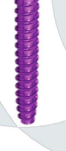
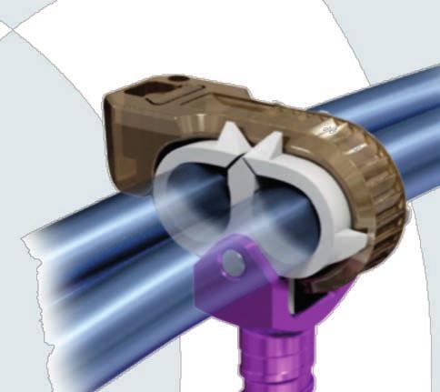
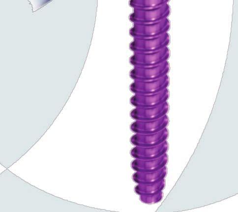
4 TROLLEY IMPLANTS AND INSTRUMENTS TROLLEY GLIDING VEHICLE IMPLANTS TROLLEY growth-guiding solution The TROLLEY solution is designed to allow for continued passive spinal growth along the rods reducing the number of lengthening surgeries and therefore, the overall morbidity of growth-friendly surgeries. PEEK TAN UHMWPE = Polyetheretherketone = Titanium Alloy = Ultra-High Molecular Weight Polyethylene 2 DePuy Synthes Surgical Technique TROLLEY
 by hand Final tighten Cable Tie with Cable Tie Pusher and Forceps for Cable Tie while reducing rod with Double Rod Pusher Cut off the overlapping")
5 INSTRUMENTS 5 steps to insert and final close a TROLLEY Gliding Vehicle (TROLLEY GV) A B C D E Insert TROLLEY GV with TROLLEY Screwdriver Use the Alignment Tool to rotate and align the TROLLEY GV with the planned rods trajectory Close Cable Tie(s) by hand Final tighten Cable Tie with Cable Tie Pusher and Forceps for Cable Tie while reducing rod with Double Rod Pusher Cut off the overlapping part of the Cable Tie with Cable Tie Cutter D E A B C TROLLEY Surgical Technique DePuy Synthes 3

6 CONCEPT AND INTRODUCTION CONCEPT The TROLLEY passive growth-guiding solution is based on the concept introduced by Eduardo R. Luque (Luque, 1982*) to guide spinal growth along a given trajectory. However, TROLLEY allows for the application of a growth-guiding construct without the use of sublaminar or cerclage wires: Guides growth following physiological sagittal alignment Implant design allows gliding of the rod at the TROLLEY GV / rod interface May reduce spontaneous fusion by keeping the rod at a distance from the bone TROLLEY is a passive growth-guiding system including specific instruments and implants (TROLLEY GVs, Cable Ties, Parallel Spacers and extra polished rods) to provide spinal deformity correction and to allow for growth of the children s immature spine. The implants provide the flexibility to accommodate a wide range of pathologies and variations in patient anatomy for the scoliotic immature thoracolumbar spine (see pages 9 and 10 for Construct Options ). * Luque, E.R. (1982): The Anatomic Basis and Development of Segmental Spinal Instrumentation. Spine 7 (3), DePuy Synthes Surgical Technique TROLLEY
7 INTRODUCTION Early-Onset Scoliosis (EOS) may have multiple causes and severe consequences. Severe spinal deformities and early spinal fusions may hinder pulmonary development of the lungs which is the primary morbidity associated with EOS that reduces life expectancy (Campbell, R.M. et al, 2004*). If traditional, conservative treatment options such as monitoring, bracing, casting are not feasible (respiratory compromise, neuromuscular etiology, compliance of wearing the brace) or are simply not successful (malignant curve progression), then surgical management should be considered. To reduce the risk of definitive early fusion in young patients (<10 years of age), surgical techniques and technologies have evolved over the last years to manage EOS. The core challenge when managing EOS is the ability to prevent curve progression while maintaining longitudinal spinal growth. The growth-guiding system TROLLEY has been designed to reduce the need for repetitive lengthening surgeries, to provide a low profile system and to reduce the risk of spontaneous fusion by keeping the rods away from the bony spinal elements. *Campbell, R.M., Jr., Smith, M.D., Mayes, T.C., Mangos, J.A., Willey-Courand, D.B., Kose, N., Pinero, R.F., Alder, M.E., Duong, H.L., and Surber, J.L. (2004). The effect of opening wedge thoracostomy on thoracic insufficiency syndrome associated with fused ribs and congenital scoliosis. J. Bone Joint Surg. Am. 86-A, TROLLEY Surgical Technique DePuy Synthes 5
 need to be used in conjunction with indicated pedicle screws and hooks within the thoracolumbar spine.")
8 PRECAUTIONS AND WARNINGS PRECAUTIONS The TROLLEY implants and instruments are an addition to the indicated pedicle screw systems below. TROLLEY Gliding Vehicles (TROLLEY GVs) need to be used in conjunction with indicated pedicle screws and hooks within the thoracolumbar spine. Indicated Pedicle Screw Systems Rod Diameter USS Small Stature/Pediatric and USS II Ø 5.0 / Ø 6.0 mm Pangea Ø 6.0 mm URS Ø 6.0 mm To reduce the risk of spontaneous fusion, ensure to skip minimum one level between: the TROLLEY GVs and the TROLLEY GVs and the fixed spinal anchors 6 DePuy Synthes Surgical Technique TROLLEY
9 WARNINGS Despite TROLLEY GVs having a low profile, patients may require additional wound or skin protection to prevent inadvertent rubbing or bumping of prominent implants. Overlying skin protection is recommended, so patients should initially wear a protective dressing, padding or brace on the skin overlying the implants in order to prevent rubbing or bumping of the skin, which may lead to skin breakdown. Monitoring for skin breakdown decreases the risk of deep infections. Patients with a diagnosis of spina bifida need additional surveillance due to their decreased levels of sensation. In addition to the general risks associated with spinal surgery, EOS patients undergoing this procedure have the potential to experience a high rate of complications including, but not limited to rod fracture, screw loosening/pull-out or spontaneous fusion. It is important to note that EOS patients who receive TROLLEY will need careful ongoing monitoring and may require additional surgery. TROLLEY Surgical Technique DePuy Synthes 7
10 INDICATIONS & CONTRAINDICATIONS INTENDED USE TROLLEY is a posterior passive growth-guiding solution placed in the thoracolumbar spine. It is used in combination with spinal anchors and helps to provide deformity correction of the scoliotic immature spine while allowing for continued spinal growth. INDICATIONS Progressive scoliosis with remaining growth of the spine CONTRAINDICATIONS Rigid, non-flexible spine Pedicles too small for pedicle screw implantation Skeletally mature Insufficient soft tissue to allow for proper skin coverage of implant Poor nutrition status 8 DePuy Synthes Surgical Technique TROLLEY


11 CONSTRUCT OPTIONS Disclaimer: all construct images are shown for illustrative purposes only and do not necessarily represent the exact final constructs. FOUR-ROD TECHNIQUE - Requires proximal and distal fixed anchors expected to produce local fusion - Instrument the apex of the deformities with TROLLEY GVs to achieve maximal apical translation - Growth potential stored in central telescopic, overlapping portion - Parallel Spacers are designed to reduce convergence of the two parallel rods TWO-ROD TECHNIQUES 1. Apical fusion - Requires apical fusion with fixed anchors allowing for apical deformity correction, apical derotation. Number of level fused related to severity of deformity - Inserted pairs of TROLLEY GV two to three vertebrae away from apex proximally and distally allowing for guided growth - Growth potential is stored in the length of rod beyond the most proximal and distal TROLLEY GV TROLLEY Surgical Technique DePuy Synthes 9

12 CONSTRUCT OPTIONS 2. Distal fusion - Requires solid distal fixation and fusion typically including pelvis and / or lumbar vertebra - Growth potential stored in length of rod proximal to the last proximal TROLLEY GV - Larger diameter rod may be recommended for neuromuscular pathologies if patient anatomy permits 10 DePuy Synthes Surgical Technique TROLLEY
13 PREPARATION AND APPROACH 1 Preparation Required sets TROLLEY Instrument Set S TROLLEY Implant Set and USS Small Stature/Pediatric General Instruments USS Small Stature/Pediatric Pedicle Screws (Titanium) USS Small Stature/Pediatric Hooks (Titanium) or USS-II Pedicle Screws (Titanium) USS-II Hooks (Titanium) Transverse Connectors low profile, for Rods Ø 6.0 mm or Universal Reduction Screws in Vario Case, size 1/ Universal Reduction Screws in Vario Case, size ½ Instruments for Universal Reduction Screw in Vario Case or Set for URS Degen Instruments and Implants Set for URS Degen General Instruments Set for URS Degen Additional Instruments Various numbers Pangea The standard TROLLEY set in combination with one of the indicated pedicle screw systems contain the required implants and instruments to perform the procedure. Have the required sets readily available prior to the surgery. Have all necessary imaging readily available to plan construct type, implant placement, incision approach and to identify individual patient anatomy. TROLLEY Surgical Technique DePuy Synthes 11

14 PREPARATION AND APPROACH 2 Approach Make a midline incision spanning segments of spine to be instrumented. Three smaller midline incisions may also be used. For fixed spinal anchors, insert spinal fixation through classic subperiosteal dissection as these segments will be fused. Please refer to the surgical technique guide of the corresponding pedicle screw systems. For the insertion of TROLLEY Gliding Vehicles (TROLLEY GVs) use a transmuscular approach, sparing joints and minimizing bony exposure to reduce the risk of spontaneous fusion. At the thoracic levels, use a lateral to midline erector spinae* insertion technique, dissecting directly onto the transverse process, avoiding exposure of the lamina. Use of fluoroscopic guidance to confirm pedicle entry point is crucial. Notes: - * Dissection at the area where TROLLEY GVs are to be inserted should be kept at a minimum, using extraperiosteal and muscle sparing techniques to reduce the risk of spontaneous fusion (Ouellet,J. (2011). Surgical technique: Modern Luque Trolley, a self-growing rod technique. Clinical orthopaedics and related research 469, ) - Additionally, the depth of the TROLLEY GV is crucial. If left too superficial, skin breakdown may occur. Conversely, if TROLLEY GVs are inserted too deep, the rods will be resting on the bone or facet joints above and below, increasing the risk of early spontaneous fusion 12 DePuy Synthes Surgical Technique TROLLEY

15 SCREW INSERTION 1 Perforate cortex of pedicle and prepare for insertion Locate pedicles and use the Awl of the corresponding screw diameter from the chosen pedicle screw system to perforate the cortex. Use the Probe of the corresponding screw diameter to open the pedicle canal. Alternatively, taps can be used to perform this procedure. Using radiographic imaging, confirm the pedicle location, orientation and depth. When selecting the appropriate length of the TROLLEY GV, use the markings on the Probe to determine the pedicle depth. Use the Feeler to check pedicle canal integrity prior to insertion of the TROLLEY GV. Notes: - Do not use the Pedicle Awl or the Pedicle Probe for any screws that are smaller or bigger than the corresponding size - Additional care must be taken as EOS patients tend to have small pedicles. Therefore, the use of radiographic imaging is crucial to locate pedicles and to reduce the risk of malpositioned screws - Screw entry points between levels should deviate as little as possible. This will ensure good alignment of the TROLLEY GV and reduce stresses in the final construct. Keeping the rods parallel to each other is an important factor to allow guided growth TROLLEY Surgical Technique DePuy Synthes 13
16 SCREW INSERTION 2 TROLLEY GV Selection TROLLEY GVs are placed at strategic points across the deformity based on curve patterns and construct type used. Refer to the section Construct Options (pages 9 and 10) to choose the proper approach according to the region of the spine for TROLLEY GV placement. Choose the corresponding TROLLEY GV, either with single or double bearing. 14 DePuy Synthes Surgical Technique TROLLEY
.")
. 2 3 4 Precaution: The TROLLEY Screwdriver (03.")
17 3 Assemble TROLLEY Screwdriver to TROLLEY GV 1 Instruments TROLLEY Screwdriver All TROLLEY GVs will be delivered in sterile packaging. Assemble the TROLLEY Screwdriver with the unpacked TROLLEY GVs with applicator. The correct orientation of the screw portion is ensured by the driver geometry (1). The TROLLEY GV with applicator is introduced into the Screwdriver by pushing it into the guide (2). Push the applicator into the Screwdriver until it is completely inserted (3). Once the TROLLEY GV with applicator is fully inserted, lock it into place by turning the wheel on the Screwdriver clockwise into the CLOSE position (4) Precaution: The TROLLEY Screwdriver ( ) can only be used with TROLLEY GVs. Note: Make sure the TROLLEY Screwdriver is in the OPEN position prior to TROLEY GV insertion. TROLLEY Surgical Technique DePuy Synthes 15


18 SCREW INSERTION 4 Insert TROLLEY GVs 1 Instruments TROLLEY Screwdriver The TROLLEY GV can now be inserted into the prepared pedicle under fluoroscopic control. Advance the TROLLEY GV until it is just slightly above the bony surface. The depth of screw insertion can be determined by looking at the skin level. The orientation of the Cable Tie lock is given by the pictogram on top of the TROLLEY GV applicator (1). The lock on the pictogram should look towards the midline to ensure that in the closed position the lock is placed lateral. Visibility in the wound can be increased by slightly pulling up the Screwdriver. For backing up the Screwdriver, make sure you do not completely release the Cable Tie from the applicator. Notes: - The TROLLEY GVs are self-tapping pedicle screws however, if tapping is preferred, use the appropriate Tap and Tap Handle of indicated pedicle screw systems - Make sure to keep the operation site free of disturbing soft tissues 16 DePuy Synthes Surgical Technique TROLLEY

19 5 Remove TROLLEY Screwdriver Instruments TROLLEY Screwdriver The TROLLEY Screwdriver can be removed by simply pulling on the instrument. The applicator of the TROLLEY GV will be removed within the same step. To remove the applicator from the TROLLEY Screwdriver turn the wheel on the Screwdriver counterclockwise to the OPEN position (1) and pull out the applicator (2). The single use applicator can then be disposed. 1 2 TROLLEY Surgical Technique DePuy Synthes 17
20 SCREW INSERTION 6 Insert remaining TROLLEY GVs Instruments TROLLEY Screwdriver Continue inserting the remaining TROLLEY GVs by repeating the previous steps 1-5. Notes: - Make sure to insert the remaining TROLLEY GVs appropriately to allow rod insertion - To reduce the risk of spontaneous fusion ensure to skip minimum one level between the TROLLEY GVs 18 DePuy Synthes Surgical Technique TROLLEY
21 7 Align TROLLEY GVs Instruments TROLLEY Alignment Tool For orientation and depth adjustment of the TROLLEY GV pedicle screw, the TROLLEY Alignment Tool is placed over the Cable Tie and rod bearing onto the screw portion of the TROLLEY GV. Notes: - Orientation and depth adjustment is crucial to ensure ease of Cable Tie closure. If the TROLLEY GV bearing surface is not aligned to the rod then Cable Tie closure may be difficult and may result in asymmetrical wear of the bearing. This is particularly important when using a TROLLEY GV with double bearing - Depth adjustment is particularly important for TROLLEY GVs in adjacent vertebrae as a difference in depth may lead to difficulties in closing the Cable Tie - Ideally, the Cable Tie lock is placed lateral in the final position. A midline position for the lock is not recommended due to potential conflicts with the spinous processes - Always check if the Cable Tie is mobile before insertion of the rod (1) 1 TROLLEY Surgical Technique DePuy Synthes 19
22 ROD INSERTION Precautions: - Insert remaining fixed spinal anchors according to chosen construct type prior to rod insertion - Select appropriate rod diameter (Ø 5.0/6.0 mm) depending on chosen pedicle screw system and patient anatomy - For larger, neuromuscular patients a Ø 6.0 mm might be beneficial Note: To reduce the risk of spontaneous fusion ensure to skip minimum one level between the TROLLEY GVs and the fixed spinal anchors 1 Determine rod contour and length Determine required length and cut the rod to length according to expected growth and patient anatomy with a universal 5.0/6.0 mm Rod Cutter. Notes: - Choose appropriate rod length to allow for growth of the spine without significant soft tissue disturbance - Make sure to cut the rods appropriately at the flat end to reduce the risk of sharp rod ends (do not cut the rod at the blunt tip end as this is important to ease rod tunneling) - Bend the rods to match the spinal anchor locations - Bend the rods in respect to the expected growth potential (for TROLLEY GVs) - Rod contouring needs to be done carefully to produce smooth curves and to avoid any notches 20 DePuy Synthes Surgical Technique TROLLEY

23 2a Four-rod technique Contour and insert rods Contour the polished rods according to your preferred sagittal profile (planned curve correction) and cut the rods (attached at proximally fixed anchors) to travel the length of the spine till they just reach the distally fixed anchors. Similarly, the rods (attached at the distally fixed anchors) should travel just proximal to the proximal fixed anchors. Insertion of the rods can be done either from the proximal or distal incision, tunneling the blunt tip towards the middle incision and engaging the TROLLEY GV bearing. Using the sagittal curve of the rods, they can be rotated partially facilitating the insertion of the rods and capturing the spinal implants. The rods should be passed subfascially, without touching any bony surface. Precautions: - Insert the rod with the blunt tip first to reduce soft tissue or implant damage - Check that the rods can slide freely after assembly and are separated from each other TROLLEY Surgical Technique DePuy Synthes 21
24 ROD INSERTION Notes: - Ensure that overlapping rods are aligned to each other as parallel as possible in the gliding section to allow for controlled spinal guided growth - Leave sufficient overlap at the gliding free ends. The overlap dictates the growth potential stored in the construct - Do not reverse or over-bend the rods. Reverse or repeated bending produces internal stresses, which may become the focal point for early failure of the implant - Mishandling of the rod causing surface damage can reduce the gliding potential of the construct - Bend rods appropriately to allow insertion into the TROLLEY GVs as well as fixed spinal anchors and use Parallel Spacers to separate the rods - Rod bending in the gliding zone (proximity of TROLLEY GVs) may compromise the gliding capabilities of the construct - Minimize muscle contusion during rod insertion 22 DePuy Synthes Surgical Technique TROLLEY


25 2a Four-rod technique Parallel Spacer (intended to be used in four-rod constructs only) Instruments Holding Forceps for Rib Hook Cap Parallel Spacers can be used to guide and separate the rods from each other to prevent rod impingement. 1 2 Begin placement by clipping the Parallel Spacer onto one of the rods (1) using the Holding Forceps ( ) and in a second step the Parallel Spacer will be pushed over the second rod (2). Use a TROLLEY Cable Tie to secure the Parallel Spacer. The Cable Tie Pusher in combination with the Holding Forceps for Cable Tie is used to close the Cable Tie (page 26) and the Cable Cutter to cut the Cable Tie (page 30). Notes: - Parallel Spacers are designed to reduce convergence of the two parallel rods. Direct contact of the rods could cause wear debris - Therefore, it is recommended to implant Parallel Spacers at long intersections in four-rod constructs - Be aware that Parallel Spacers might migrate during spinal growth. This does not affect functionality - The use of Parallel Spacers is appropriate for fourrod constructs only where two parallel rods are placed on the same run of pedicle screws and interconnected to each other TROLLEY Surgical Technique DePuy Synthes 23

 and pull.")
26 ROD INSERTION 2a Four-rod technique Insertion of Cable Tie for Parallel Spacer 1 Instruments TROLLEY Holding Forceps for Cable Tie To secure the Parallel Spacer to the rods, an additional Cable Tie will be used. It is recommended to bend the tip of the Cable Tie by hand (1) and thread it mediolateral through the TROLLEY GV bearing. Grip the Cable Tie with the TROLLEY Holding Forceps for Cable Tie ( ) and pull. Note: Do not bend the Cable Tie at the hole location where you put the Holding Forceps as this may compromise the closing procedure 24 DePuy Synthes Surgical Technique TROLLEY

27 2b Two-rod technique Contour and insert rods Contour the polished rods according to your planned sagittal profile. Insertion of the rods can be done either from the proximal or distal incision, tunneling the blunt tip towards the middle incision and engaging the TROLLEY GV bearing. Using the sagittal curve of the rods, they can be rotated partially facilitating the insertion of the rods and capturing the spinal implants. The rods should be passed subfascially, without touching any bony surface. Precautions: - Insert the rod with the blunt tip first to reduce soft tissue or implant damage - Check that the rods can slide freely after assembly Notes: - Leave sufficient overlap at the gliding free ends. The overlap dictates the growth potential stored in the construct - Do not reverse or over-bend the rods. Reverse or repeated bending produces internal stresses, which may become the focal point for early failure of the implant - Mishandling of the rods causing surface damage can reduce the gliding potential of the construct - Bend rods appropriately to allow insertion into the TROLLEY GVs as well as fixed spinal anchors - Rod bending in the gliding zone (proximity of TROLLEY GVs) may compromise the gliding capabilities of the construct - Minimize muscle contusion during rod insertion TROLLEY Surgical Technique DePuy Synthes 25

28 FINAL TIGHTENING 1 Close Cable Ties by hand Close the TROLLEY Cable Ties over the rods by inserting the tip of the TROLLEY Cable Tie into the closure until the first teeth are engaged, approximately after ~30 mm. Continue pulling by hand in one swift motion making sure that the cable does not bind or kink. ~30 mm Note: Cable Ties cannot be reopened again. If required, the Cable Tie needs to be cut and replaced (see chapter Components Assembly, page 35). 26 DePuy Synthes Surgical Technique TROLLEY
 to reduce rods.")

29 2 Final closure of TROLLEY Gliding Vehicles Instruments TROLLEY Holding Forceps for Cable Tie TROLLEY Cable Tie Pusher Double Rod Pusher, for Rods Ø 5.0/6.0 mm Precaution: Do not use the Cable Tie for rod reduction. Use the Double Rod Pusher(s) to reduce rods. Notes: - When using the Double Rod Pusher(s), apply forces perpendicular to the rod only to avoid slippage of the Double Rod Pusher(s) - Always use the Double Rod Pusher(s) as it establishes the recommended space between the two rods The Cable Ties have to be sequentially closed, gradually capturing the rods. Deformity correction must be achieved by cantilevering the rods into parallel constructs and or undertaking rod derotation maneuvers with partially captured rods at three points of spinal fixation. Once the correction has been achieved, position the Double Rod Pushers next to the TROLLEY GVs to push the rod into the bearing of the TROLLEY GVs. To close the Cable Ties use the Cable Tie Pusher and the Holding Forceps. By levering the Holding Forceps on the Cable Tie Pusher and pulling on the Cable Tie, the Cable Tie can be closed. Proceed in a sequential fashion, final tightening all Cable Ties. TROLLEY Surgical Technique DePuy Synthes 27


30 FINAL TIGHTENING Do not attempt to correct the deformity by simply pulling on the Cable Tie as the Cable Tie is not indicated for such a maneuver. To prevent overtightening a fail-safe feature is incorporated in the design of the Cable Tie. When high tightening forces are applied, the tip will break off to limit forces on the lock. The broken off part will be secured in the forceps. Note: Avoid scratching the rods with the Double Rod Pusher(s) 28 DePuy Synthes Surgical Technique TROLLEY


31 Note: Make sure that the rod(s) is (are) fully seated inside the TROLLEY GV bearing and that the bearing is firmly wrapped around the rod(s) CORRECT INCORRECT TROLLEY Surgical Technique DePuy Synthes 29
.")

32 FINAL TIGHTENING 3 Cutting off Cable Tie ends 1 Instruments TROLLEY Cable Cutter for Cable Tie Precaution: Before cutting the Cable Tie ends, ensure that the rods are fully seated inside the bearing of the TROLLEY GV (see previous page). Then, make sure to align the TROLLEY Cable Cutter for Cable Tie before cutting to avoid damage to the Cable Tie. Before cutting the end of the Cable Tie, ensure that all Cable Ties and bearings are firmly wrapped around the rods. Use the TROLLEY Cable Cutter for Cable Tie to cut off the overhanging ends of the Cable Tie. Make sure that the head of the Cable Cutter is flush with the closure (1) to minimize protrusion sharp edges. Note: Maintain pressure on Cable Cutter handle when removing to prevent cut-off portion of Cable Tie from falling into the wound. 30 DePuy Synthes Surgical Technique TROLLEY

 Fluoroscopic imaging (AP and")

33 FINALIZE CONSTRUCT 1 Finalize construct Finalize the TROLLEY construct using fixed spinal anchors and TROLLEY GV on the contra-lateral side. Final tighten fixed spinal anchors according to surgical technique guide of indicated systems. Precaution: Use TROLLEY with indicated systems only (page 6) Fluoroscopic imaging (AP and lateral X-rays) may be crucial to control final construct positioning and achieved correction. The Cable Tie includes a radiopaque marker pin for enhanced visualization indicating the position of the lock. TROLLEY Surgical Technique DePuy Synthes 31
34 CONTINUUM OF CARE 1 Replacement of rod(s) Patients who have outgrown their TROLLEY constructs, (= less than 2 TROLLEY GVs are connected per rod end) need a replacement of their rod(s) with longer one(s) to allow further growth of the spine: Please perform the following steps below: 1. Cut open all Cable Ties by following the steps described in chapter Removal of Trolley Gliding Vehicle (page 36) 2. Follow the steps described in chapter Components Assembly (page 34) to insert new Cable Ties into the TROLLEY GVs 3. For the rod insertion procedure please perform the steps described in the chapter Rod Insertion (page 20) 4. Perform the final tightening procedure described in the chapter Final Tightening (page 26) 5. Finalize the construct by following the steps described in the chapter Finalize Construct (page 31) 32 DePuy Synthes Surgical Technique TROLLEY


35 ADDITIONAL IMPLANTS FOR STABILIZATION 1 Use of transverse connectors Precaution: Do not use transverse connectors in the gliding zone as it will negatively affect the construct s ability to support growth. For additional rotational stability transverse connectors can be mounted depending on the construct type chosen, either cranially and/or caudally or in the apex. The transverse connectors need to be placed between a pair of fixed spinal anchors. Choose the appropriate transverse connector with respect to the implanted rod diameter. For Ø 5.0 mm rods, transverse connectors from the USS Small Stature/Pediatric sets can be used. For Ø 6.0 mm rods, transverse connectors from the URS or USS II sets can be used. For instructions of use for the selected transverse connector please refer to the surgical technique of the corresponding system. Note: Transverse connectors are to be taken from the fixed pedicle screw system used to anchor the construct. There are no specific transverse connectors provided with the TROLLEY set. Following transverse connectors can be used from the USS Small Stature/Pediatric set: Transverse Connector, low profile, for Rods Ø 5.0 mm, Titanium Alloy (TAN), light blue Following transverse connectors can be used from the URS or USS II sets: Transverse Connector, low profile, for rods Ø6 mm TROLLEY Surgical Technique DePuy Synthes 33

36 COMPONENTS ASSEMBLY 1 Insertion of Cable Tie 1 Instruments TROLLEY Holding Forceps for Cable Tie In cases where the Cable Tie is accidentally removed from the TROLLEY Gliding Vehicle or in case of revision surgery, the Cable Tie can be inserted manually. It is recommended to bend the tip of the Cable Tie by hand (1) and push it through the TROLLEY GV bearing. Then, the Cable Tie can be pulled up either by hand or with the TROLLEY Holding Forceps for Cable Tie ( ). Notes: - Make sure that the bearing of the TROLLEY GV is still intact before inserting a new Cable Tie. If the bearing is damaged, the TROLLEY GV needs to be replaced completely - Do not bend the Cable Tie at the hole location where you put the Holding Forceps as this may compromise the closing procedure 34 DePuy Synthes Surgical Technique TROLLEY

37 2 Reassembly of TROLLEY GV to TROLLEY applicator 1 Instruments TROLLEY Screwdriver 2 In cases where the TROLLEY GV has been separated from the Screwdriver before the screw portion is inserted, the TROLLEY GV can be manually reassembled. Match the Cable Tie head to the notch on the applicator and push the applicator into the TROLLEY GV (1). Hold the Cable Tie ends toward the applicator (2) and slide the first ring on the holder down to the end of the applicator (3). 3 Slide the second ring over the lock of the Cable Tie (4). The TROLLEY GV construct can now be reinserted into the TROLLEY Screwdriver ( ), (page 16). 4 TROLLEY Surgical Technique DePuy Synthes 35

 is required for complete removal of the TROLLEY GV. The TROLLEY Alignment Tool can be used as a screwdriver to remove the TROLLEY GV.")
38 REMOVAL OF TROLLEY GLIDING VEHICLE 1 Removal of TROLLEY GV Instruments Cable Cutter, standard TROLLEY Alignment Tool Optional Cable Cutter for Cable Tie For removal of the Cable Ties and the TROLLEY GVs, the Cable Tie has to be cut. It cannot be reused. For cutting of the Cable Tie use the Cable Cutter, standard ( ). Alternatively, the Cable Cutter for Cable Tie ( ) can be used. Removal of the Cable Tie and rod(s) is required for complete removal of the TROLLEY GV. The TROLLEY Alignment Tool can be used as a screwdriver to remove the TROLLEY GV. Note: In case of revision surgeries (e.g. rod needs to be replaced) cut all Cable Ties with the Cable Cutter, then replace the implanted rod with a longer one and follow the steps described in the chapter Components Assembly (page 34) to insert new Cable Ties. 36 DePuy Synthes Surgical Technique TROLLEY
39 ASSEMBLY / DISASSEMBLY INSTRUCTIONS ASSEMBLY INSTRUCTIONS TROLLEY Screwdriver DISASSEMBLY INSTRUCTIONS TROLLEY Screwdriver TROLLEY Surgical Technique DePuy Synthes 37
40 IMPLANTS S S TROLLEY GV, Pedicle Screw, for two Rods, sterile S S TROLLEY GV, Pedicle Screw, for one Rod, sterile S TROLLEY Parallel Spacer, sterile S TROLLEY Cable Tie, length 170 mm, sterile S S TROLLEY Rod Ø 5.0 mm, with blunt tip, length 300/400/500 mm, polished, Titanium Alloy (TAN), sterile S S TROLLEY Rod Ø 6.0 mm, with blunt tip, length 300/400/500 mm, polished, Titanium Alloy (TAN), sterile Description Lengths for two Rods for one Rod TROLLEY GV, Pedicle Screw Ø 4.0 mm, length 15 mm, sterile 15 mm S S TROLLEY GV, Pedicle Screw Ø 4.0 mm, length 20 mm, sterile 20 mm S S TROLLEY GV, Pedicle Screw Ø 4.0 mm, length 25 mm, sterile 25 mm S S TROLLEY GV, Pedicle Screw Ø 4.0 mm, length 30 mm, sterile 30 mm S S TROLLEY GV, Pedicle Screw Ø 4.0 mm, length 35 mm, sterile 35 mm S S TROLLEY GV, Pedicle Screw Ø 4.0 mm, length 40 mm, sterile 40 mm S S TROLLEY GV, Pedicle Screw Ø 5.0 mm, length 20 mm, sterile TROLLEY GV, Pedicle Screw Ø 5.0 mm, length 25 mm, sterile TROLLEY GV, Pedicle Screw Ø 5.0 mm, length 30 mm, sterile TROLLEY GV, Pedicle Screw Ø 5.0 mm, length 35 mm, sterile TROLLEY GV, Pedicle Screw Ø 5.0 mm, length 40 mm, sterile TROLLEY GV, Pedicle Screw Ø 5.0 mm, length 45 mm, sterile 20 mm S S 25 mm S S 30 mm S S 35 mm S S 40 mm S S 45 mm S S 38 DePuy Synthes Surgical Technique TROLLEY
41 TROLLEY GV, Pedicle Screw Ø 6.0 mm, length 20 mm, sterile TROLLEY GV, Pedicle Screw Ø 6.0 mm, length 25 mm, sterile TROLLEY GV, Pedicle Screw Ø 6.0 mm, length 30 mm, sterile TROLLEY GV, Pedicle Screw Ø 6.0 mm, length 35 mm, sterile TROLLEY GV, Pedicle Screw Ø 6.0 mm, length 40 mm, sterile TROLLEY GV, Pedicle Screw Ø 6.0 mm, length 45 mm, sterile TROLLEY GV, Pedicle Screw Ø 6.0 mm, length 50 mm, sterile 20 mm S S 25 mm S S 30 mm S S 35 mm S S 40 mm S S 45 mm S S 50 mm S S TROLLEY Surgical Technique DePuy Synthes 39


42 INSTRUMENTS TROLLEY Screwdriver TROLLEY Holding Forceps for Cable Tie TROLLEY Alignment Tool TROLLEY Cable Tie Pusher Double Rod Pusher, for Rods Ø 5.0/6.0 mm TROLLEY Cable Cutter for Cable Tie Holding Forceps for Rib Hook Cap Cable Cutter, standard 40 DePuy Synthes Surgical Technique TROLLEY


43 TROLLEY SET LIST Modular tray Module for TROLLEY Instruments Instruments TROLLEY Screwdriver TROLLEY Holding Forceps for Cable Tie TROLLEY Alignment Tool TROLLEY Cable Tie Pusher Double Rod Pusher, for Rods Ø 5.0/6.0 mm TROLLEY Cable Cutter for Cable Tie Holding Forceps for Rib Hook Cap Cable Cutter, standard Lid for modular tray Lid for Modular Tray, Next Generation, size 1/1 TROLLEY Surgical Technique DePuy Synthes 41
44
45 TROLLEY Surgical Technique DePuy Synthes 43

46 Synthes GmbH Eimattstrasse Oberdorf Switzerland Tel: Fax: Not all products are currently available in all markets. This publication is not intended for distribution in the USA. All surgical techniques are available as PDF files at
Slotted ConneCtorS 4. Fixed BoltS 8. Fixed reduction BoltS 10. Polyaxial BoltS 12. Polyaxial reduction BoltS 13. iliac BoltS and SCrewS 14
 Product Catalogue Contents Slotted ConneCtorS 4 Fixed BoltS 8 Fixed reduction BoltS 10 Polyaxial BoltS 12 Polyaxial reduction BoltS 13 iliac BoltS and SCrewS 14 lateral ConneCtorS 15 HookS 15 wires 17
Surgical Technique REVERE Stabilization System
 Surgical Technique REVERE 6.35 Stabilization System At Globus, we move with a sense of urgency to deliver innovations that improve the quality of life for patients with spinal disorders. We are inspired
Consensus Orthopedics Inc. Bespoke ACO Polyamide Acetabular Cup Orientation (ACO) guides and ACO bone models
 guides and ACO bone models") Consensus Orthopedics Inc. Bespoke ACO Polyamide Acetabular Cup Orientation (ACO) guides and ACO bone models IMPORTANT INFORMATION FOR SURGEON: PLEASE READ PRIOR TO USING THIS DEVICE IN A CLINICAL SETTING.
Consensus Orthopedics Inc. Bespoke ACO Polyamide Acetabular Cup Orientation (ACO) guides and ACO bone models IMPORTANT INFORMATION FOR SURGEON: PLEASE READ PRIOR TO USING THIS DEVICE IN A CLINICAL SETTING.
Shadow-Line spine retractor system
 Shadow-Line spine retractor system V. Mueller neuro/spine instruments V. Mueller Shadow-Line spine retraction system Versatility by design CareFusion brings a new angle to spinal surgery with its versatile
Designed to address the unpredictable. ZMR Hip System
 Designed to address the unpredictable ZMR Hip System Modularity When and Where it s Needed The ZMR Hip System is designed to provide exceptional intraoperative flexibility and versatility to meet the unpredictable
Fore- and Midfoot System 2.0 / 2.3, 2.8
 PRODUCT INFORMATION Fore- and Midfoot System 2.0 / 2.3, 2.8 APTUS Foot 2 Fore- and Midfoot System 2.0 / 2.3, 2.8 Fore- and Midfoot System 2.0 / 2.3, 2.8 Multidirectional and angular stable treatment of
BML-3Q-1 BML-4Q-1 USA: CAUTION:
 INSTRUCTIONS MECHANICAL LITHOTRIPTOR BML-3Q-1 BML-4Q-1 USA: CAUTION: Federal law restricts this device to sale by or on the order of a physician. 0197 Contents Contents Symbols Important Information Please
Vercise PC Implantable Pulse Generator
 Vercise PC Implantable Pulse Generator Directions for Use CAUTION: Federal law restricts this device to sale, distribution and use by or on the order of a physician. 92104390-01 Content: 92116333 REV B
Nuclear Associates CLEAR-Pb
 Nuclear Associates CLEAR-Pb Transparent X-Ray Compensation Filters For Spinal Radiography User Manual February 2005 Manual No. 38609 Rev. 2 2004, 2005 Fluke Corporation, All rights reserved. All product
MatrixPRO Driver Instructions for Use
 DESCRIPTION: The MatrixPRO Driver (05.000.020) is designed to insert DePuy Synthes MatrixNEURO TM Self-Drilling Screws (3-4mm lengths) and Low Profile Neuro Self-Drilling Screws (3-4mm lengths) and features
Installation Manual TWM Performance Short Shifter Cobalt SS/SC, SS/TC, HHR SS, Ion Redline and Saab 9-3
 Page 1 Installation Manual TWM Performance Short Shifter Cobalt SS/SC, SS/TC, HHR SS, Ion Redline and Saab 9-3 Please Note: It is preferable to park on a flat surface, as you will have to engage and disengage
PRODUCT INFORMATION MDO 2.0. MODUS Mandible
 PRODUCT INFORMATION MDO 2.0 MODUS Mandible 2 MDO 2.0 MDO * 2.0 Modular Distraction Osteogenesis System The Medartis MDO 2.0 distraction system offers the user easy intraoperative handling. The system has
Installation Instructions. QuickSilver Shifter. Fits: GM, Ford, Chrysler Transmissions See Application Guide for Specific Applications Part # 80683
 Installation Instructions QuickSilver Shifter Fits: GM, Ford, Chrysler Transmissions See Application Guide for Specific Applications Part # 80683 WORK SAFELY! For maximum safety, perform this installation
Electric Pen Drive. Compact system for a wide range of applications.
 Electric Pen Drive. Compact system for a wide range of applications. Ergonomic drive unit with powerful motor Extensive range of attachments and tools Simple operation Synthes Electric Pen Drive System
Blades with the MatrixPRO Driver may result in damage to the MatrixPRO Driver and/or screwdriver blades, and should
 Description: The MatrixPRO Driver (05.000.020) is designed to insert DePuy Synthes MatrixNEURO TM Self Drilling Screws (3 4mm lengths) and Low Profile Neuro Self Drilling Screws (3 4mm lengths) and features
Bookwalter. Self-Retaining Retractor Catalog. Good exposure is the key to good surgery John Bookwalter, M.D.
 Bookwalter Self-Retaining Retractor Catalog Good exposure is the key to good surgery John Bookwalter, M.D. INDEX COMPONENT Horizontal Bars and Posts 6-8 Blades and Post Coupling 9-3 Ratchets 4-5 Rings
(Refer to qualified personnel)
") 3875 Cypress Drive Petaluma, CA 94954 800.228.2555 +1.707.773.1100 Fax 707.773.1180 www.gcx.com Installation Guide VHM-P (Non-Locking) and VHM-PL (Locking) Variable Height Arm (Slide-Above-Arm Configuration)
3875 Cypress Drive Petaluma, CA 94954 800.228.2555 +1.707.773.1100 Fax 707.773.1180 www.gcx.com Installation Guide VHM-P (Non-Locking) and VHM-PL (Locking) Variable Height Arm (Slide-Above-Arm Configuration)
Innovating for life. aortic.medtronicendovascular.com. Medtronic Vascular, Inc Unocal Place Santa Rosa, CA USA
 aortic.medtronicendovascular.com Medtronic Vascular, Inc. 3576 Unocal Place Santa Rosa, CA 95403 USA Product Services Support Center Tel:.23.76 Fax: 00.3.3103 CardioVascular LifeLine Customer Support Tel:
Seatpan and backrest angles can be adjusted independently, usually with two separate levers
 Feature Explanation Considerations Standard Features & Options Synchronous Mechanism Relationship between seatpan and backrest is linked so that the angles adjust in a fixed ratio. Typically, the backrest
Porsche 911/996/997 Carrera Do-It-Yourself Convertible Top Hydraulic Cylinder Inspection, Removal and Shipping Instructions
 Porsche 911/996/997 Carrera Do-It-Yourself Convertible Top Hydraulic Cylinder Inspection, Removal and Shipping Instructions Disclaimer: These instructions are intended as a guide. Cabriolet Hydraulics
ICON Back System. Product Training. Icon Back System
 ICON Back System Product Training Innovation Versatility Comfort Simplicity Easy to Use Features and Models Available in 4 models Icon Low Back Icon Mid Back Icon Tall Back Icon Deep Back New design Hardware
TADRMO s Dual-Top Temporary Anchorage Device
 Dual-Top temporary anchorage device () RMO s Dual-Top Temporary Anchorage Device () system provides efficient and flexible biomechanics. Dual-Top s significantly enhance treatment capabilities and can
Nevro Lead Compatibility
 Nevro Lead Compatibility Directions for Use 91131569-01 REV B CAUTION: Federal law restricts this device to sale, distribution and use by or on the order of a physician. Guarantees Boston Scientific Corporation
PET UNIT DOSE TABLE INSTALLATION MANUAL FN: Rev A 1/18
 PET UNIT DOSE TABLE INSTALLATION MANUAL 042-448 FN: 09-243 Rev A 1/18 Pet Unit Dose Table This manual covers installation procedures for the following products: 042-448 Table, PET, Unit Dose 2 Biodex Medical
Delivery System for Hernia Mesh Fixation
 Delivery System for Hernia Mesh Fixation Design Team Joseph Aaron, Andrew Edgerly Charles O Connell, Charles Sidoti, David Stone Design Advisor Dr. Jeffrey Ruberti Sponsor High Road Medical Abstract The
Standard Compression Dead End for ACSR and ACSS Conductor CAUTION: ACSR Dead Ends Cannot Be Used on ACSS HT Conductor
 INS-ACA089 Installation Instructions Standard Compression Dead End for ACSR and ACSS Conductor CAUTION: ACSR Dead Ends Cannot Be Used on ACSS HT Conductor 1. Mark the conductor a distance of 3 /4 the length
Installation, Operation, and Maintenance Manual
 Industrial Process Installation, Operation, and Maintenance Manual Series PBV Plastic Lined Ball Valve Table of Contents Table of Contents Introduction and Safety...2 Safety message levels...2 User health
THE BENCHMARK FOR SURGICAL VERSATILITY. Surgical Solutions. One Integrated Approach to Healthcare STERIS 5085 AND 5085 SRT SURGICAL TABLES
 Surgical Solutions THE BENCHMARK FOR SURGICAL VERSATILITY STERIS 5085 AND 5085 SRT SURGICAL TABLES ADVANCING CARE THROUGH PRACTICAL INNOVATION One Integrated Approach to Healthcare THE ANSWER TO TODAY
Installation, Operation, and Maintenance Manual
 Installation, Operation, and Maintenance Manual Welker Automatic Insertion Heated Regulator High Voltage Model IHRA-4SS-220/230 100 or more inch insertion length The information in this manual has been
HOW - TO WIRING & LIGHTING
 HOW - TO WIRING & LIGHTING Tool And Material Checklist Test Light Service Manual Penetrating Oil Long-Nose Pliers T-Square or Right Angle Screwdriver Black Electrical Tape Fuses Fuse Puller Cloth or Paper
Tech Note Truck 14 & 15.5 Twin Plate Cast Iron Type Installation Guidelines
 1. (14 & 15.5 ) Check condition of the flywheel. Grind to resurface or replace flywheel. Surface MUST BE machined or premature clutch failure can occur. Flywheel depth must be 2.938 (74.62mm) for 14 (350mm)
Installation Instructions Z-Gate Shifter
 Installation Instructions Z-Gate Shifter Part Number 80681 1998, 2001 by B&M Racing and Performance Products The B&M Z-Gate shifter can be used in vehicles equipped with most popular three speed automatic
Final Assembly Instructions Portside Cruiser
 Final Assembly Instructions Portside Cruiser Thank you for buying your new bicycle from L.L.Bean. Read these instructions carefully before beginning the final assembly. Prior to shipping, our expert cycling
INSTALLATION INSTRUCTIONS
 INSTALLATION INSTRUCTIONS [1] Description: Tow Hitch Wire Harness Kit [2] Application: Nissan Rogue Note: Tow Harness application is limited to specific vehicle option packages that include tow harness
Ride Custom Systems Face Sheet :~)
") Ride Designs a branch of Aspen Seating, LLC toll-free 866.781.1633 phone 303.781.1633 fax 303.781.1722 www.ridedesigns.com Ride Custom Systems Face Sheet :~) Please fill in one face sheet per client order.
Ride Designs a branch of Aspen Seating, LLC toll-free 866.781.1633 phone 303.781.1633 fax 303.781.1722 www.ridedesigns.com Ride Custom Systems Face Sheet :~) Please fill in one face sheet per client order.
Placing a World of Possibilities in Your Hands
 Placing a World of Possibilities in Your Hands Special instructions for storage and use: Storage conditions the ITAL prosthesis may be safely stored and transported in temperatures ranging from 22 o F
This document goes through the basic steps required to utilize the electric window motors from the Ford Mk3 Mondeo.
 Modifying Ford Mk3 Mondeo door glass motors The options for installing electric windows in a Diablo replica are limited to only a few options; You can install the original motor and cable runners at 500
VHM-P (Non-Locking) Variable Height Arm with VESA Mounting Plate for 75 x 75mm or 100 x 100mm applications
 Variable Height Arm with VESA Mounting Plate for 75 x 75mm or 100 x 100mm applications") 3875 Cypress Drive Petaluma, CA 94954 800.228.2555 +1.707.773.1100 Fax 707.773.1180 www.gcx.com VHM-P (Non-Locking) Variable Height Arm with VESA Mounting Plate for 75 x 75mm or 100 x 100mm applications
3875 Cypress Drive Petaluma, CA 94954 800.228.2555 +1.707.773.1100 Fax 707.773.1180 www.gcx.com VHM-P (Non-Locking) Variable Height Arm with VESA Mounting Plate for 75 x 75mm or 100 x 100mm applications
INSPECTION TECHNIQUE FOR BWR CORE SPRAY THERMAL SLEEVE WELD
 More Info at Open Access Database www.ndt.net/?id=18479 INSPECTION TECHNIQUE FOR BWR CORE SPRAY THERMAL SLEEVE WELD ABSTRACT J.L. Fisher, G. Light, Jim Crane, Albert Parvin, Southwest Research Institute,
Test-A-Pack Seal Strength Tester F The most important thing we build is trust. Testing Range. Key Features. Ordering Information
 Test-A-Pack 2600 Seal Strength Tester P/N: F100-2600-3 The most important thing we build is trust The Cobham Test-A-Pack Model F100-2600-3 Seal Strength Tester is the heart of the world s most advanced
2013 RT / 2014RT / 2015 RT - Shock Spring Adjuster Installation Instructions
 2013 RT / 2014RT / 2015 RT - Shock Spring Adjuster Installation Instructions Billet Aluminum Adjusters (2) Shock Spring Compressors (Optional) Spanner Wrench (1) BajaRon Decals Not Shown (4) Adjuster Scuff
TOYOTA TUNDRA TVIP V4 Preparation
 Preparation Part Number: PT398-00100 PT398-00100-AA Conflicts Do not install into vehicles without RKE system. Recommended Sequence of Application Item # Accessory 1 TVIP/RES Any TVIP or RES system 2 XM
CROSBY SERIES 800 AND 900 OMNI-TRIM PRESSURE RELIEF VALVES INSTALLATION AND MAINTENANCE INSTRUCTIONS
 any and all liability arising out of the same. Any installation, maintenance, adjustment, repair and testing performed on pressure relief valves should be done in accordance with the requirements of all
2.- HANDLING OF VALVES BEFORE ASSEMBLY 3.- FITTING THE VALVE TO THE REST OF THE ASSEMBLY 5.- PERIODICAL INSPECTION OF THE VALVE AND MAINTENANCE
 Page 1 of 16 CONTENTS 1.- INTRODUCTION 2.- HANDLING OF VALVES BEFORE ASSEMBLY 3.- FITTING THE VALVE TO THE REST OF THE ASSEMBLY 4.- OPERATION OF A BALL VALVE 5.- PERIODICAL INSPECTION OF THE VALVE AND
Transmission Overhaul Procedures-Bench Service
 How to Assemble the Lower Reverse Idler Gear Assembly Special Instructions In 1996 Eaton changed the reverse idler system design. In the nut design, the reverse idler bearing was lubricated through a hole
VHM-P (Non-Locking) and VHM-PL (Locking) Variable Height Arm with Slide-In Mounting Plate
 and VHM-PL (Locking) Variable Height Arm with Slide-In Mounting Plate") 3875 Cypress Drive Petaluma, CA 94954 800.228.2555 +1.707.773.1100 Fax 707.773.1180 www.gcx.com VHM-P (Non-Locking) and VHM-PL (Locking) Variable Height Arm with Slide-In Mounting Plate (Refer to qualified
3875 Cypress Drive Petaluma, CA 94954 800.228.2555 +1.707.773.1100 Fax 707.773.1180 www.gcx.com VHM-P (Non-Locking) and VHM-PL (Locking) Variable Height Arm with Slide-In Mounting Plate (Refer to qualified
TBI /2012 TRAUMATIC BRAIN INJURY DEVICE
 USER MANUAL TBI 0310 6/2012 TRAUMATIC BRAIN INJURY DEVICE Page 1 of 26 Setting up the TBI 0310 Head Impactor The TBI 0310 Head Impactor when fully assembled has the following components: 1. Control box
5. E-axis assembly. 5. E-axis assembly. Written By: Jakub Dolezal manual.prusa3d.com/ Page 1 of 40
 5. E-axis assembly Written By: Jakub Dolezal 2018 manual.prusa3d.com/ Page 1 of 40 Step 1 Tools necessary for this chapter Needle-nose pliers for zip tie trimming. 2.5mm Allen key for M3 screws 2mm Allen
PET UNIT DOSE CABINET
 PET UNIT DOSE CABINET INSTALLATION MANUAL 244-200 244-205 FN: 08-134 Rev A 11/17 Pet Unit Dose Cabinet This manual covers operation procedures for the following products: 244-200 Cabinet, PET, Unit Dose
The alternative to being bedridden
 The alternative to being bedridden INGLESE COD. 220166-16-01-2017 design and quality MADE IN ITALY since 1980 Ergonomic sitting, it supports and holds shapes Optimal shift pressure Hygienic and breathable
Z-Gate Universal Shifter
 Installation Instructions Z-Gate Universal Shifter Fits: GM, Ford, Lincoln and Chrysler Transmissions See Application Guide for Specific Applications Part #80681 Rev 06/01/2018 WORK SAFELY! For maximum
Final Assembly Instructions: Runaround Cruiser
 Final Assembly Instructions: Runaround Cruiser Thank you for buying your new bicycle from L.L.Bean. Read these instructions carefully before beginning the final assembly. Prior to shipping, our expert
Installation Instructions QUICKSILVER CONSOLE SHIFTER Fits: Chevelle / El Camino
 WORK SAFELY! For maximum safety, perform this installation on a clean, level surface and with the engine turned off. Place blocks or wedges in front of and behind both rear wheels to prevent movement in
Back. Ride Custom Back Order Form
 Back Client First and Last Name NOTE: This order form must be accompanied by a Ride Custom Seating Systems Face Sheet. Prices effective November 1, 2012. Ride Custom Back (Model #: RCB100) Medicare HCPCS
Service Manual. Bolens 683 Series Box Frame Tractor IMPORTANT: READ SAFETY RULES AND INSTRUCTIONS CAREFULLY
 Service Manual Bolens 683 Series Box Frame Tractor IMPORTANT: READ SAFETY RULES AND INSTRUCTIONS CAREFULLY This Service Manual is not a substitute for the Operator s Manual. You must read, understand and
Southwest Windpower Instruction Sheet AIR-X Circuit Replacement Kit
 Southwest Windpower Instruction Sheet AIR-X Circuit Replacement Kit Tools Required 5 / 32 Hex key 5 / 16 Hex key 7 / 64 Hex key Standard screwdriver Pair of external snap ring pliers Rubber mallet Hammer
Photo 1. Shift pattern gate plate
 Installation Instructions MAGNUM GRIP STREET BANDIT SHIFTER Fits: GM, Chrysler, and Ford Automatic Transmissions See Application Guide for Specific Vehicles Catalog # 81050 WORK SAFELY! For maximum safety,
OPERATIONS MANUAL LEVER CHAIN HOIST
 OPERATIONS MANUAL LEVER CHAIN HOIST IMPORTANT SAFETY INFORMATION Please read, understand and follow all safety information contained in these instructions prior to the use of this hoist. Retain these instructions
INSTALLATION GUIDES DekaFlex Connectors DEKAFLEX MC-HL CONNECTOR INSTALLATION GUIDE FOR HAZARDOUS LOCATIONS
 INSTALLATION GUIDES DekaFlex Connectors DEKAFLEX MC-HL CONNECTOR INSTALLATION GUIDE FOR HAZARDOUS LOCATIONS INTRODUCTION Dekoron s DekaFlex armored cables are a revolution in the armored cable industry
Final Assembly Instructions: Bikes with Threadless Headsets
 Final Assembly Instructions: Bikes with Threadless Headsets Thank you for buying your new bicycle from L.L.Bean. Read these instructions carefully before beginning the final assembly. Prior to shipping,
THORACOSCOPIC LAPAROSCOPIC
 Aesculap Spine Miaspas TL Spinal Microsurgical Endoscopy THORACOSCOPIC LAPAROSCOPIC CONTENTS PAGE INTRODUCTION 3 RONGEURS AND NUCLEUS-GRASPING FORCEPS 5 BONE PUNCHES 6 APPLICATION OF THE SLIDING TUBE 7
354 CHAPTER EIGHT WATER PUMP
 354 CHAPTER EIGHT 33 Shift handle F : Forward N : Neutral R : Reverse proper alignment of the water tube to the water pump opening during each installation attempt. Make sure the locating pins enter the
Vercise Gevia 16 Contact Implantable Pulse Generator
 Vercise Gevia 16 Contact Implantable Pulse Generator Directions for Use CAUTION: Federal law restricts this device to sale, distribution and use by or on the order of a physician. 92152386-01 Content:
PRO RATCHET UNIVERSAL SHIFTER
 Installation Instructions PRO RATCHET UNIVERSAL SHIFTER Fits: GM, Ford and Chryslers w/automatic Transmission See Application Guide for Specific Vehicles Catalog # 80842 WORK SAFELY! For maximum safety,
Wallace Tri-Adjustable Gantry Cranes Square Tube Assembly Instructions
 Wallace Tri-Adjustable Gantry Cranes Square Tube Assembly Instructions For any additional information, Please call 1- S 1. Read and understand instructions before using this gantry. 2. Inspect gantry thoroughly
HEADQUARTER
 HEADQUARTER Since 1990 Aditek has innovated the world of orthodontic market with high-tech products and processes. Today the company is recognized as one of the leading orthodontic products manufacturer
Caring for cables. Types of installation
 Caring for cables Cable carriers guide and protect cables and hoses on moving machinery, and prevent tangling or damage from debris or contact with the machine itself. Proper use of a cable carrier extends
A Recommended Approach to Pipe Stress Analysis to Avoid Compressor Piping Integrity Risk
 A Recommended Approach to Pipe Stress Analysis to Avoid Compressor Piping Integrity Risk by: Kelly Eberle, P.Eng. Beta Machinery Analysis Calgary, AB Canada keberle@betamachinery.com keywords: reciprocating
Installation Instructions Right Hand Drive Megashifter
 Installation Instructions Right Hand Drive Megashifter Part Number 80685 1995, 2001, 2006, 2010 by B&M Racing & Performance Products The B&M Right Hand Drive Megashifter is designed specifically for vehicles
Maintenance & Repair Manual
 SM64055 November 2012 Aerospace Group Conveyance Systems Division Applicable additional manuals: None Carter Brand Ground Fueling Equipment Maintenance & Repair Manual 4 Inch Internal/Bottom Loading Valves
Installation Instructions Console Megashifter
 Installation Instructions Console Megashifter 1968-1969 Camaro Part Number 81035 This B&M Megashifter is designed to fit in the console of a 1968-1969 Chevrolet Camaro. In 1968, these vehicles were equipped
TOWARDS A UNIVERSAL COUPLER DESIGN FOR MODERN POWERED PROSTHESES
 TOWARDS A UNIVERSAL COUPLER DESIGN FOR MODERN POWERED PROSTHESES Levi G. Sutton 1, Adam Clawson 2, T. Walley Williams III 3, James H. Lipsey 1, Jonathon W. Sensinger 1,4 1. Rehabilitation Institute of
PARTS CATALOGUE / TECHNICAL GUIDE
 PARTS CATALOGUE / TECHNICAL GUIDE PARTS CATALOGUE / TECHNICAL GUIDE (p. 1 21) CATÁLOGO DE PARTES / GUÍA TÉCNICA (p. 23 43) [SPECIFICATIONS] Item Movement Cal. No. 5J22A (x 1.0) Movement size Outside diameter
1 Product Description System Layout Safety Instructions Intended Use Installation... 3
 Order Number 0812xx- Contents 1 Product Description... 2 2 System Layout... 2 3 Safety Instructions... 3 4 Intended Use... 3 5 Installation... 3 5.1 Hanger Clamp... 3 5.2 Cutting of Conductor Rail... 4
Crispin Valves Operating Guide. Crispin
 Crispin Valves Operating Guide Crispin Since 1905 Crispin Multiplex Manufacturing Co. 600 Fowler Avenue Berwick, PA 18603 1-800-AIR-VALV T: (570) 752-4524 F: (570) 752-4962 www.crispinvalve.com sales@crispinvalve.com
Hurst VMATIC3 INSTALLATION
 FORM 159 8530 07/12 Hurst VMATIC3 3-Speed & 4-Speed Automatic Shifter Catalog #3838530 2012 by Hurst Performance The Hurst Vmatic3 shifter can be used in vehicles equipped with most popular three speed
CP2000 Ballast - Replacing Thyristor Instruction Sheet
 CP2000 Ballast - Replacing Thyristor Instruction Sheet INTRODUCTION These instructions are for the CP2000 Ballast and explain how to: replace the existing 80 Amp Thyristor with a new 100 Amp Thyristor
Installation Instructions Megashifter
 Installation Instructions Megashifter The B&M Megashifter shifter can be used in vehicles equipped with most popular three speed or four speed automatic transmissions. Your B&M Megashifter comes equipped
(51) Int Cl.: B66C 13/14 ( ) B66C 3/00 ( ) A01G 23/08 ( ) E02F 9/22 ( ) E02F 3/36 ( )
 Int Cl.: B66C 13/14 ( ) B66C 3/00 ( ) A01G 23/08 ( ) E02F 9/22 ( ) E02F 3/36 ( )") (19) TEPZZ 8 4Z59A_T (11) EP 2 824 059 A1 (12) EUROPEAN PATENT APPLICATION (43) Date of publication: 14.01.2015 Bulletin 2015/03 (21) Application number: 13181144.0 (51) Int Cl.: B66C 13/14 (2006.01) B66C
(19) TEPZZ 8 4Z59A_T (11) EP 2 824 059 A1 (12) EUROPEAN PATENT APPLICATION (43) Date of publication: 14.01.2015 Bulletin 2015/03 (21) Application number: 13181144.0 (51) Int Cl.: B66C 13/14 (2006.01) B66C
Interlocks 200 Series
 rd 12070 43 St. NE, St. Michael, MN 55376 763-497-7000 www.tcamerican.com sales@tcamerican.com Installation Instructions Interlocks 200 Series 2I-515; 2I-930 2I-513; 2I-850 Crane Interlock and Operating
5 Removal and replacement
 5 Removal and replacement This chapter describes the removal and replacement of field-replaceable units (FRUs) only. Removal and replacement strategy User-replaceable parts Covers Internal assemblies ENWW
Hydraulic Wheel Dolly Owner's Manual Contents Introduction Safety Precautions Operating Instructions Specifications
 Alberth Aviation Hydraulic Wheel Dolly HWD40 Hydraulic Wheel Dolly Owner's Manual Contents Introduction Safety Precautions Operating Instructions Specifications A full demonstration video is online at
DEPARTMENT OF THE NAVY DIVISION NEWPORT OFFICE OF COUNSEL PHONE: FAX: DSN:
 WAVSEA WARFARE CENTERS NEWPORT DEPARTMENT OF THE NAVY NAVAL UNDERSEA WARFARE CENTER DIVISION NEWPORT OFFICE OF COUNSEL PHONE: 401 832-3653 FAX: 401 832-4432 DSN: 432-3653 Attorney Docket No. 85033 Date:
Two-way cable interlock kit for Magnum fixed circuit breakers
 warning (1) Only qualified electrical personnel should be permitted to work on the equipment. (2) Always de-energize primary and secondary circuits if a circuit breaker cannot be removed to a safe work
GPS AutoSteer System Installation Manual
 GPS AutoSteer System Installation Manual John Deere Track Supported Models 8295RT 8320RT 8345RT PN: 602-0255-01-A LEGAL DISCLAIMER Note: Read and follow ALL instructions in this manual carefully before
Interlocks 325 Series
 rd 12070 43 St. NE, St. Michael, MN 55376 763-497-7000 www.tcamerican.com sales@tcamerican.com Installation Instructions Interlocks 325 Series 3I-615; 3I-430 3I-613; 3I-450 Crane Interlock and Operating
TOYOTA VENZA 2009 TRAILER WIRE HARNESS Procedure
 Part Number: PT791-0T099 Kit Contents Item # Quantity Reqd. Description 1 1 Trailer Wire Harness Module 2 1 4-Flat Harness 3 1 Battery Power Wire Harness 4 1 Mounting Bracket, 4-Flat 5 2 Screw #10-24 6
Maintenance Information
 16572679 Edition 2 May 2014 Air Drill QP Series Maintenance Information Save These Instructions Product Safety Information WARNING Failure to observe the following warnings, and to avoid these potentially
GPS Steering System Installation Manual
 GPS Steering System Installation Manual Supported Vehicles Challenger Massey Ferguson AGCO MT-645C, MT-645D MF-8650 DT-205B MT-655C, MT-655D MF-8660 DT-225B MT-665C, MT-665D MF-8670 DT-250B MT-675C, MT-675D
TOYOTA TUNDRA TVIP V4 REMOTE ENGINE STARTER (RES)
") Preparation Part Number: 08586-OC910 Conflicts Do not install into vehicles without RKE systems. Recommended Sequence of Application Item # Accessory 1 TVIP/RES Any TVIP or RES system 2 XM Radio NOTE:
Preparation Part Number: 08586-OC910 Conflicts Do not install into vehicles without RKE systems. Recommended Sequence of Application Item # Accessory 1 TVIP/RES Any TVIP or RES system 2 XM Radio NOTE:
Motor systems for Implantology and Oral Surgery
 Motor systems for Implantology and Oral Surgery 67095 EN V10/17 NOUVAG AG, all rights reserved Subject to change 1 We talk Implantology 2 Motor systems for Implantology 3 A motor system capable of perfectly
Desktop 5.5 Z Axis Retrofit
 Page 1 Kit parts Desktop 5.5 Z Axis Retrofit Carriage plate with stop bolt and Z proximity switch installed Zip ties Spare bolts Spindle mounting plate with stop bolt, spring mount, and rail Z proximity
Stainless Steel Theatre Furniture. Stainless Steel Theatre Furniture. Manufactured to the highest possible standards
 Stainless Steel Theatre Furniture PRODUCT INDEX Page Instrument Trolleys (Shelves Fixed Down-turned) 4 25000 Instrument trolley 450 x 450 x 850mm 25010 Instrument trolley 600 x 450 x 850mm 25020 Instrument
TCI FastGate Shifter Installation Instructions
 151 INDUSTRIAL DRIVE ASHLAND, MISSISSIPPI 38603 http://www.tciauto.com TELEPHONE: 662-224-8972 FAX LINE: 662-224-8255 E-MAIL: tech@tciauto.com TCI 616541 FastGate Shifter Installation Instructions The
The instruments are powered by nitrogen or compressed air and require no lubrication. The instruments and hose are steam autoclavable.
 The MicroAire Series 1000 Power Instrument System is a unitized pneumatic small power system. The precision instruments are lightweight yet durable. The specially designed thin blades provide smooth and
Instructions for Use Reprocessed HARMONIC ACE Shears without Adaptive Tissue Technology. Reprocessed Device for Single Use.
 Reprocessed by Instructions for Use Reprocessed HARMONIC ACE Shears without Adaptive Tissue Technology Reprocessed Device for Single Use Caution: Federal (U.S.A.) law restricts this device to sale by or
FAX
 INSTALLATION INSTRUCTIONS 6090 Air Suspension Kit (pat. pending) 1999-2006 Tahoe, Suburban, Avalanche, Yukon Thank you for purchasing a quality Hellwig Product. PLEASE READ THIS INSTRUCTION SHEET COMPLETELY
Fiber optic splice closure
 FOSC-450A I N S T A L L A T I O N I N S T R U C T I O N TC-772-IP Rev A, Mar 2017 www.commscope.com Fiber optic splice closure Content 1 Introduction 2 General 2.1 Kit content 2.2 Tools 2.3 Accessories
Maintenance Information
 Form 04584058 Edition 1 November 2004 Air Impactool 2141P and 2141PSP Maintenance Information Save These Instructions Disassembly General Instructions 1. Do not disassemble the tool any further than necessary
Installation Instructions StarShifter
 Installation Instructions StarShifter Part Number 80675 2000 by B&M Racing & Performance Products LLC The B&M StarShifter can be used in vehicles equipped with most popular three speed automatic transmissions.