Gasoline Injectors Tester With Ultrasonic Cleaner Gs2 INSTRUCTION MANUAL
|
|
|
- Camron Walsh
- 5 years ago
- Views:
Transcription

 6036107, Faks: + 48 (032) 603-61-08 e-mail:")
1 Gasoline Injectors Tester With Ultrasonic Cleaner Gs2 INSTRUCTION MANUAL Magneti Marelli Aftermarket Spółka z.o.o. Plac Pod Lipami 5, Katowice Tel.: + 48 (032) , Faks: + 48 (032) checkstar@magnetimarelli.com
2 Copyright The distribution and sales of the product are intended for use by the original purchaser. This document may not, in whole or part, be copied, photocopied, reproduced, translated or reduced to any electronic medium of machine-readable form without prior consent in writing from Magneti Marelli. The information in this document is subject to change without notice. Warranty 2 Year Gs Series Limited Warranty Magneti Marelli company manufactures its equipment from new parts and components that are in accordance with industry standard practices. Magneti Marelli warrants that the equipment it manufactures will be free of defects in materials and workmanship. The warranty terms are 2 years, beginning on the date of the Magneti Marelli invoice in accordance with the following described: This warranty does not cover damage due to external causes, including accident, abuse, misuse, scratches on external components or surfaces, problems with electrical power supply, servicing not authorized by Magneti Marelli, usage not in accordance with machine s operating manual, failure to perform required preventative maintenance, failure to change the testing calibration oil fluid and ultrasonic cleaning fluid regularly, failure to change the testing fluid filter when needed, to permit machines fluid pump to sit or operate without fluid in it, usage of improper testing or cleaning fluid in the machine, usage of improper ultrasonic cleaning fluid in the ultrasonic bath, usage of ultrasonic fluid instead of testing fluid or the opposite, usage of cleaning solvents and chemicals not provided or indicated/approved by Magneti Marelli, use of parts and components not supplied or approved by Magneti Marelli.
3 Note: Failure to clean injectors with Magneti Marelli s ultrasonic device before any test is performed on the GS Series test bench will void the warranty of the machine, if dirt particles from the injectors enter the GS valves. Magneti Marelli will repair or replace parts and components returned to manufacturer s facility. To request warranty service, contact Magneti Marelli within the warranty period. If warranty service is required, you must ship the defective part or component in their original or equivalent packaging, prepay shipping charges, and insure, or accept the risk of loss or damage during shipment. Magneti Marelli will return the repaired or replacement part or component freight prepaid. If Magneti Marelli repairs or replaces a part or component, its warranty term is Not Extended. Magneti Marelli does not accept liability beyond the remedies set forth in this warranty statement or liability for incidental or consequential damages.
4 Chapter 1 Introduction Through the years, there has been an excess demand in Pollution Reduction, Fuel Economy and Enhanced Performance for Consumer Engines (Automobiles & Motorcycles). Engine Manufacturers have gone a long way, since Carburetor Engines, to reach today at the revolutionary approach of Electronically Controlled Injection (Port Injection & Direct Injection). With this approach they have successfully reduced emissions and gained fuel economy through accurate injection of fuel. The Electronically Controlled Fuel Injectors, although accurate, produce chronicle defects. Through time numerous faults may occur, such as fuel residue built-up (at nozzle), electrical coil failure and injector pathway blockage. These faults in turn, produce an undesired effect which causes increase in emissions, increase in fuel consumption, unstable engine operation and loss of engine performance. Magneti Marelli, a leading manufacturer in Automotive Injection Service Solutions, offers the GS Series units for the treatment of all Electronically Controlled Fuel Injectors presently used (MPFI, TBI, CIS, G-DI / FSI), and provides upgradeability of the machine for Future Injectors yet to come.
5 Equipment checklist Carefully unpack the machine and its components. Save the box and packaging materials for future use. Check if you have all the following items: - GS Series Gasoline Injector Testing and Servicing Unit - Injector Ultrasonic Device [100/240 VAC] with: o Operating Manual o AC Power Cord[100/240 VAC] o Injector Holder - AC [100/240 VAC] Power Cord, for GS Series Unit - Calibrating Oil, prefilled tank with start-up consumable for Testing injectors - 4 liter Calibration Oil, start-up consumable for GS Testing injectors - 4 liter Ultrasonic Cleaning Solvent, start-up consumable for Ultrasonic Cleaning injectors - Calibration Oil/Fluid Funnel Small - Adapters and Accessories Kit for Testing Injectors - Injector Test Rail(s) - Portable Stand [Optional] - Operating Manual and Quality Control Certificate
6 Options There are a number of options to make the GS units even more powerful and universal in diagnosing and servicing the Gasoline Injectors. The following options are available: Code Description Hardware Needed Models EXCL- Exclusive Adapters Kit for 8 GSx- YES ADAPT.4/8 or 4 injectors 1XXX TBI-ADAPT Side Adapters Kit YES GSx- 1XXX SRC-505 Screen Filter extractor tool YES - PS1 / PS2 Portable stand GS Series YES GSx- XXX0
7 Machine & Adapters Chapter 2 Machine & Adapters This chapter provides an overview of the GS Series exterior views and connections. It covers the following topics: - Machine Views - Injector Test Rails - Adapters A new user should be familiar with all the views and connections in this chapter.
8 Front View a. Injector Harness [ih]: Provides electrical signal to the injectors b. Fluid Supply hose[fs]: Provides pressurized fluid to the Test Rail(s) c. Test Rail(s): Provide fluid to the injectors d. Injection Spray chambers: Lit chambers for viewing the injection spray pattern e. Scaled Volumetric Tubes: used to measure and compare the volume displaced by the injectors f. Testing Calibration Oil level indicator g. Control Panel h. Pressure Indicator (analog gauge) i. Reverse Flushing device: used to wash the injector remaining dirt particles after cleaning j. Reverse Flushing Device injector harness k. Reverse Flushing device waste tray l. (Gasoline Injectors): Not Provided

9 Machine & Adapters a b l c d e f i j k g h Figure 2-i
 c. Side Panel d.")
, for ultrasonic device f.")
10 Side/Rear View a. Drain Lever: Used to drain the GS2 volumetric tubes. Lift to empty. b. Reverse Flushing Device (GS2 units) c. Side Panel d. Mains, Rear ON/OFF switch and Power connection e. Mains Loop Power Connection (Auto-Switched), for ultrasonic device f. Rear Bottom Panel g. Serial Tag a d e f g b c Figure 2-ii

11 Machine & Adapters Injector Test Rails The Exclusive Test Rail, Figure 2-iv, is the most versatile test rail, since the user can fit up to 4 top-feed injectors or up to 4 side-feed injectors at a time, on each rail. Through a complete combination of adapters provided in the exclusive Adapters Kit, the user is capable of fitting any top-feed or side-feed injector on this test rail. Figure 2-iii, Test Rail Handle (HNDL-1) Figure 2-iv, Test Rail Exclusive (TESTRAIL-EX) i) Machine Fluid Hose Connector ii) Exclusive Injector Adapter Housings iii) Test Rail Handle (HNDL-1)
 Figure 2-vi, Test Rail Standard Top-Feed (TESTRAIL-STD.")
12 The Standard Top-Feed Test Rail, Figure 2-vi, is used solely for Top-Feed injectors, and can fit up to 4 top-feed injectors at a time. Figure 2-v, Test Rail Handle (HNDL-1) Figure 2-vi, Test Rail Standard Top-Feed (TESTRAIL-STD.TOP) i) Machine Fluid Hose Connector ii) Standard Injector Adapter Thread iii) Test Rail Handle (HNDL-1)
 Figure 2-viii, Test Rail Standard Side-Feed (TESTRAIL-STD.")
13 Machine & Adapters The Standard Side-Feed Test Rail, Figure 2-viii,is used solely for Side-Feed injectors, and can fit up to 1 side-feed injector at a time. Figure 2-vii, Test Rail Handle (HNDL-1) Figure 2-viii, Test Rail Standard Side-Feed (TESTRAIL-STD.SIDE) i) Machine Fluid Hose Connector ii) Standard Injector Adapter Housings iii) Test Rail Handle (HNDL-1)
: (HNDL-2) [GSx-2xxx only] H")
 [GSx-2xxx")
![only] Top-Feed Injector Adapter: (ADAPT-1) ADAPT-1](/docs-images/89/99415757/images/14-2.jpg "(ORNG-001) TOP SIDE O-rings: (ORNG-002) BOTTOM SIDE")
14 Top-Feed Adapters ADAPTER FIGURE DESCRIPTION Adapter Handle (Short): (HNDL-2) [GSx-2xxx only] H Shaped Injector Adapter: (ADAPT- H ) [GSx-2xxx only] Adapter Height Adjuster: (ADJ-1) [GSx-2xxx only] Top-Feed Injector Adapter: (ADAPT-1) ADAPT-1 (ORNG-001) TOP SIDE O-rings: (ORNG-002) BOTTOM SIDE [GSx-2xxx only]
 ii) Hose Adapter (ADAPT-TOP.HOSE) iii) Long Wide Top feed Adapter (ADAPT-TOP.")
 vi) Blinder (ADAPT-SEAL) Top-Feed Injector fitting O- ring: (ORNG-003) Test Rail Spacer: i.")
15 Machine & Adapters Top-Feed Injector fittings: i) CIS Adapter (ADAPT-TOP.CIS) ii) Hose Adapter (ADAPT-TOP.HOSE) iii) Long Wide Top feed Adapter (ADAPT-TOP.3) iv) Wide Top feed Adapter (ADAPT-TOP.2) v) Narrow Top feed Adapter (ADAPT-TOP.1) vi) Blinder (ADAPT-SEAL) Top-Feed Injector fitting O- ring: (ORNG-003) Test Rail Spacer: i. Height 45mm (COL-45) ii. Height 60mm (COL-60) iii. Height 90mm (COL-90)
![Side-Feed Adapters (Type A) ADAPTER FIGURE DESCRIPTION Adapter Handle (Short): (HNDL-2) [GSx-2xxx only] i. E Shaped Injector Adapter: (ADAPT- E ) ii.](/docs-images/89/99415757/images/16-2.jpg "H Shaped Injector Adapter: (ADAPT- H ) Side-Feed Injector fittings Type(A): i. (ADAPT-SIDE.A1) [GSx-2xxx only] ii. (ADAPT-SIDE.A2) iii. (ADAPT-SIDE.A3) iv. (ADAPT-SIDE.A4) v. (ADAPT-SIDE.A5) vi.")
16 Side-Feed Adapters (Type A) ADAPTER FIGURE DESCRIPTION Adapter Handle (Short): (HNDL-2) [GSx-2xxx only] i. E Shaped Injector Adapter: (ADAPT- E ) ii. H Shaped Injector Adapter: (ADAPT- H ) Side-Feed Injector fittings Type(A): i. (ADAPT-SIDE.A1) [GSx-2xxx only] ii. (ADAPT-SIDE.A2) iii. (ADAPT-SIDE.A3) iv. (ADAPT-SIDE.A4) v. (ADAPT-SIDE.A5) vi. (ADAPT-SIDE.A6) [GSx- 2xxx only] Side-Feed Injector fitting O- ring Type(A): (ORNG-004)
: (ADAPT-2) ADAPT-2 (ORNG-001) TOP SIDE O-rings: (ORNG-002) BOTTOM SIDE ii.")
17 Machine & Adapters i. Side-Feed Injector Adapter Type(A): (ADAPT-2) ADAPT-2 (ORNG-001) TOP SIDE O-rings: (ORNG-002) BOTTOM SIDE ii. ADAPT-2 extra (ORNG-005) O-ring: [GSx-2xxx only] Side-Feed Injector Connectors: i. (CON-1) ii. (CON-2) iii. (CON-3) iv. (CON-4)
![Side-Feed Adapters (Type B) ADAPTER FIGURE DESCRIPTION Adapter Handle (Short): (HNDL-2) [GSx-2xxx only] i. E Shaped Injector Adapter: (ADAPT- E ) ii.](/docs-images/89/99415757/images/18-2.jpg "H Shaped Injector Adapter: (ADAPT- H ) Side-Feed Injector fittings Type(B): i. (ADAPT-SIDE.B1) ii. (ADAPT-SIDE.B2) iii. (ADAPT-SIDE.B3) iv. (ADAPT-SIDE.B4) Side-Feed Injector fitting O-ring Type(B): (ORNG-006) Thick O-ring (ORNG-007) Thin O-ring")
18 Side-Feed Adapters (Type B) ADAPTER FIGURE DESCRIPTION Adapter Handle (Short): (HNDL-2) [GSx-2xxx only] i. E Shaped Injector Adapter: (ADAPT- E ) ii. H Shaped Injector Adapter: (ADAPT- H ) Side-Feed Injector fittings Type(B): i. (ADAPT-SIDE.B1) ii. (ADAPT-SIDE.B2) iii. (ADAPT-SIDE.B3) iv. (ADAPT-SIDE.B4) Side-Feed Injector fitting O-ring Type(B): (ORNG-006) Thick O-ring (ORNG-007) Thin O-ring
 BOTTOM SIDE [GSx-2xxx only] Side-Feed Injector Connectors: i. (CON-1) ii. (CON-2) iii. (CON-3) iv.")
19 Machine & Adapters Side-Feed Injector Adapter Type(B): (ADAPT-3) ADAPT-3 (ORNG-001) TOP SIDE O-rings: (ORNG-002) BOTTOM SIDE [GSx-2xxx only] Side-Feed Injector Connectors: i. (CON-1) ii. (CON-2) iii. (CON-3) iv. (CON-4)
 ii) Larger opening Reverse Flushing Adapter (ADAPT-BF.2) These adapters, are used solely for the Reverse Flushing device and the only difference is the injector opening.")
20 Other Adapters Reverse Flushing Adapters Figure 2-ix, Reverse Flushing Adapters i) Smaller opening Reverse Flushing Adapter (ADAPT-BF.1) ii) Larger opening Reverse Flushing Adapter (ADAPT-BF.2) These adapters, are used solely for the Reverse Flushing device and the only difference is the injector opening. Use what best fits the injector type.
 ii) Ultrasonic Rail for Side-Feed Injectors (RAIL-US.2) Use the ultrasonic rails RAIL-US.1 or RAIL-US.")
21 Machine & Adapters Ultrasonic Rails i) ii) Figure 2-x, Ultrasonic Unit Bath Rails i) Ultrasonic Rail for Top-Feed Injectors (RAIL-US.1) ii) Ultrasonic Rail for Side-Feed Injectors (RAIL-US.2) Use the ultrasonic rails RAIL-US.1 or RAIL-US.2, according to the type of injector.
22
23 Getting Started Chapter 3 Getting Started This chapter provides basic information to start using the GS Series unit and covers the following topics: [info] All users should be familiar with diesel systems and should always wear protective goggles and gloves. - Unpacking and setting up - Connecting the AC and the Ultrasonic power - Starting up for the first time - Powering down the system - Testing Fluid - Ultrasonic Fluid A new user should follow the steps in each section of this chapter in order to operate the machine.
24 Unpacking and setting up - Verify that all the items in the equipment check list in Chapter 1 are present - Place the GS Series Unit and Ultrasonic Device in a clean and well ventilated space - Use a leveled, steady bench that can support the weight of the machine, or use the PS1/PS2 Portable Stand [optional].
 2.")
25 Connecting the AC and the Ultrasonic power Getting Started GS Series Unit Verify that the rear ON/OFF Power Switch is in the OFF position. 1. Connect one end of the AC power cord [a] to the rear power socket of the machine [b] (Figure 3-i) 2. Connect the other end of the AC Power cord to any grounded 100/240 VAC, 50/60 Hz power source (live wall outlet) [b] [a] Figure 3-i


26 Injector Ultrasonic Device 1. Connect one end of the AC power cord to the rear power socket of the device 2. Connect the other end of the AC Power cord to the GS unit loop back connection, depending on the Ultrasonic device specifications. Also switch on the ultrasonic device if applicable, using the Rear On/Off switch. [info] Please consult the accompanying Ultrasonic device Operating Manual.
27 Getting Started Starting up for the first time 1. Switch to the ON position the rear power Switch. 0: OFF / I: ON 2. Wait a few seconds until the GS Series Software Boots up. If more than 1 minute pass and the Software has not loaded (Blank screen), consult your local dealer. 3. Once the software loads, the initial screen will show the S/W and H/W version of the machine 4. Look in Chapter 4 Control Panel for further information on software navigation. [important] - Always wait at least 15 seconds when switching on the unit again (after a power down) Powering down the system 1. Press the CANCEL button for more than 3 seconds until the Home screen is revealed 2. Once this operation is complete, you can switch off the machine using rear ON/OFF Power.

28 Testing Fluid The GS Series comes with a tank of Testing fluid (Gasoline Calibration oil) / (Figure 3-ii). In order to fill the Testing tank up to acceptable level, you must use the accompanied funnel and pour liquid through the Spray Chambers. Press the Drain button (lift the Drain lever [GS2 units]), in order to empty filled tubes into the tank. Figure 3-ii [info] - Always check if you have acceptable levels of fluids. [important] - Never operate the machine if the fluid is not within acceptable levels. - It is recommended to clean the injectors with the ultrasonic device before installing on the machine in order to avoid fluid and filter contamination.
29 Getting Started Ultrasonic Fluid Pour a mixture of Distilled water and Ultrasonic Fluid in the Ultrasonic bath (1:3), and fill up to 2/3 or the marked line. [info] - Always consult device manual and fluid labeling. [important] - Never operate the device if the fluid is not within acceptable levels. Add water or refill with mixture as needed.
30
31 Control Panel Chapter 4 Control Panel This chapter provides useful information on the GS Series Menu. It covers the following topics: - Control Panel - Language Selection - Machine Logo Customization - Procedure Screens A new user should preview all the screens in this chapter prior to operating the GS Series unit.

32 Control Panel In this section the Control Panel, buttons and features are previewed and explained. The Menu is designed for easy and simple operation. Figure 4-i a. The Display shows instructions or messages on how to proceed. b. The ENTER button is used to Confirm an action, move forward in the menu, or select an option. c. The STOP button is used to Stop / Cancel an action or move backward in the menu d. The Leak / PUMP button is used to toggle the pressure On and OFF. The Analog gauge will show the pressure in the system. e. The + / - (more/less) buttons in the Pressure control area, are used to adjust the required pressure. Each injector type has an automatic setting, therefore only fine tuning is required. f. The Drain Tubes button [GS4, GS8 only] is used to toggle the Volumetric tube drain valves ON and OFF, draining the tubes from any remaining liquid. This is also done automatically, in
33 Control Panel between programs. For the GS2 unit, the mechanical use of the side lever is required to empty the tubes. g. The Arrow Keys are used to navigate through the menu, select another option, or change a value. h. The [F]unction button is used to edit or reset a value
34 Language Selection [GS4 and GS8 only] In order to change the language of operation on the GS units the user should follow the steps below: 1. If the unit is not switched off, switch it OFF. 2. Switch the machine back ON. 3. As soon as the machine initializes, press and hold the Stop/Cancel button for more than Scroll through the available languages using the Up/Down Arrows. 5. Press the Enter/Select button to select the desired language and exit to the main menu, or press the Stop/Cancel button to exit without changing the language. Machine Logo Customization [GS4 and GS8 only] The GS units include a feature that the user can alter the Company message display on the machine. In order to customize this feature follow the instructions below: 1. If the unit is not switched off, switch it OFF. 2. Switch the machine back ON. 3. As soon as the machine initializes, press and hold the Stop/Cancel button for more than Press Right Arrow to enter the Company Logo editor.
35 Control Panel 5. Using the Left/Right Arrows select the position of the text and change the current character using the Up/Down Arrows. 6. Press the Enter/Select button to save the new logo and exit to the main menu, or press the Stop/Cancel button to exit without changing the language.
36 Procedure Screens There are several options in GS Series software, navigate the screens by using Arrow keys, and press the Enter button to select an option. 1. Engine Configuration (Vehicle / Motorcycle) [GS4 and GS8 only]: In order to proceed with the simulation and cleaning of the injectors, the user begins by selecting which type of engine the injectors come from; A vehicle Engine or a Motorcycle Engine. If Motorcycle Engine is selected, the machine continues to step 3 of this procedure. 2. Choose System (MPFI / TBI / G-DI): Here, the user should select which system the Vehicle Injectors come from: MPFI, TBI or G-DI. - MPFI or MFI (Multiport Fuel Injection), is a term broadly used to describe all port fuel injection systems. It is more accurately used to describe systems where the injectors are pulsed simultaneously (Old Type) or in groups (SFI). MPFI systems employ individual fuel injectors for each cylinder. Located in the intake manifold, the fuel injectors are timed to spray fuel into the port area when the intake valves open. The fuel injector spray-in pressure is higher on MPFI systems than TBI designs, and run generally between kpa ( psi). - TBI (Throttle Body fuel Injection), still in use today, the TBI design has full control over the air/fuel ratio. The TBI injectors can operate at various pressure levels based upon the model year of the vehicle, however generally run between kpa (11-29 psi). Lightly atomized fuel is sprayed directly into the TBI bore and engine intake manifold where it mixes with air to form a combustible mixture.
37 Control Panel - G-DI (Gasoline Direct Injection), also known as FSI, HPI, GDI, is a term broadly used to describe all direct fuel injection systems. G- DI systems employ individual fuel injectors for each cylinder, located in the combustion chamber. The fuel injectors are timed to spray fuel into the combustion chamber, in stratified or in homogeneous mode, depending on the load demanded by the engine. The fuel injector spray-in pressure is higher than all conventional fuel injection designs, and run generally between 5-13 MPa ( psi). If TBI system is selected, the machine continues to step 5 of this procedure, whereas if G-DI system is selected, the machine continues to step 4 of this procedure. 3. Injector Type (Side-Feed / Top-Feed) [GS4 and GS8 only]: With Side-Feed Port Injectors, fuel enters at the Side of the injector as opposed to the Top of the injector which is typically for Top-Feed Injectors. 5. Number of Injectors (1..8): The user should select the number of injectors currently under test. 6. Operation Program (Default / User) [GS4 and GS8 only]: The machine also provides a way for the user to select between MAGNETI MARELLIs predefined simulation programs for testing and cleaning the injectors and User defined simulation programs. Whether in Automatic mode or Manual, when the System programs are selected, the machine will execute all the System Predefined Simulation Programs. For advanced users, there is an option to select User Programs; A series of edible simulation programs that the user can create explicitly for his /her needs. Detailed information on how advanced users can create their
38 own simulation programs is provided in Advanced User - page Once either operation is selected, a prompt will follow asking the user if all the required simulation steps should follow or if the user wants specific to operate programs. 7. Progress Mode (Auto / Manual) [GS4 and GS8 only]: The GS Units provide two ways for the user to operate the machine, Automatic mode and Manual Mode. In the Automatic mode the machine goes through all the required steps of testing and cleaning the injectors, and provides detailed instructions on every action. For more advanced users, the machine can operate in Manual mode, allowing the user to select the desired operation without going through all the simulation steps selected.
39 Operation Basics Chapter 5 Operation Basics In this chapter instructions with figures will be shown on how to perform a basic operation with the GS units. The following topics are covered: - Sample Procedure on Testing Injectors o Injector Adaptation and Connection o Initial Coil Test o Initial Flow Test (Spray and Volume) o Injector Cleaning o Reverse Flushing o Final Coil & Flow Test o Leak Test o Spare Parts - Advanced User A new user should fully understand this chapter prior to operating the GS units.
40 SAFETY PRECAUTIONS ALWAYS: Check machine rail & connections for leaks. Have a fire extinguisher nearby. Wear eye goggles. NEVER: Operate the machine when leaking fluid. Disconnect under pressure. Smoke nearby machine. Operate close to open flame or sparks. CAUTION: The machine s fuel pump is capable of delivering at least 2 liters (1½ gallons) of fluid flow per minute at a pressure greater than 10 bar (150 psi).
41 Operation Basics Sample Procedure on Testing Injectors Injector Adaptation and Mounting Please consult the Appendix B, Adapters and Mounting for information on how to mount the injectors on the test rails.
![Initial Coil Test [GS4 and GS8 only] In this step, the injectors have been already fitted on the test rail and the machine conducts an (Ω) OHM test on the injector s coil (see Figure ).](/docs-images/89/99415757/images/42-0.jpg "This is the first (Initial) OHM test that is conducted by the machine and its purpose is for the user to better diagnose the injectors condition, before cleaning.")
42 Initial Coil Test [GS4 and GS8 only] In this step, the injectors have been already fitted on the test rail and the machine conducts an (Ω) OHM test on the injector s coil (see Figure ). This is the first (Initial) OHM test that is conducted by the machine and its purpose is for the user to better diagnose the injectors condition, before cleaning. Figure 5-i, Correct Ohm (Ω) Test Information is provide for 1..8 injectors and includes: i) Resistance of each Injector in OHM ii) OPEN-CIRCUIT-COIL iii) SHORT-CIRCUIT-COIL. After the OHM test is complete, the machine informs the user if there was a difference between the injector resistances.
43 Operation Basics Initial Flow Test (Spray & Volume) In order for the user to have a complete diagnosis of the injectors under test, a Bench Flow Test must be conducted. In this step the machine goes through a series of System Defined Engine Simulation Programs (see Appendix C), a combination of STRKs milliseconds time, providing the user with visual diagnosis of each injector spray pattern and volume, on different engine operation modes. An advanced user has the capability of creating his/her own combination of STRKs, milliseconds and time, from a series of User Defined Engine Simulation Programs. In this section the advanced user can create up to 7 different simulation programs with a selection of a wide range of STRKs, milliseconds and time, for every type of engine (see Table 1) Table 1, Advanced User Simulation Programs Parameters STRK ms (100 incr.) (0.1 incr.) Time Minimum Value sec Maximum Value 16, min At any time during the injectors operation the user can press the F button on the machine control panel, in order to have control of one injector independently. In other words, when the F button is pressed, only one injector at a time will spray, and by using the Left/Right Arrows the user can scroll between the injectors. In addition, advanced users can also press the INCREASE/DECREASE pressure buttons, in order to adjust the system pressure according to his/her needs. [note] Acceptable volume displacement (ml) tolerance between injectors, by vehicle manufactures, is maximum 5%.
 along with the electrical connectors of the machine.")
44 Injector Cleaning Before any operation with the Ultrasonic device, the user must assure that the device is properly Set-Up and the Ultrasonic Tank is filled with cleaning mixture. In this step, the injectors are fitted on the suitable Ultrasonic Rail (see Ultrasonic Rails, page 2-15) along with the electrical connectors of the machine. The GS Units power the Ultrasonic machine automatically once the operation has been selected from the menu. It is recommended (for better cleaning) that the user fills the injectors fuel path-way (Top-Feed Injectors) with cleaning fluid, using the Ultrasonic Injector Filler provided (see Figure 5-ii). Again an advanced user has the capability of editing a series of simulation programs provided, although that is not recommended for the ultrasonic cleaning. Figure 5-ii, Injector Fuel Path-Way Filling After the cleaning process has completed, the user should blow shop air into each injector s fuel path-way to remove as much of the residue left from the ultrasonic cleaning. The machine provides
45 Operation Basics electrical operation for all injector connectors. Instructions for this operation are provided on the machine panel display when in automatic mode. Operation of the Ultrasonic Unit Once the Ultrasonic Unit is powered up, it operates in Automatic Mode for 33 minutes. The user should always adjust the required temperature of the ultrasonic machine.
.")
46 Reverse Flushing After the injectors have been ultrasonically cleaned, the user is required to fit the injectors (on-by-one) on the Reverse Flushing device. This device pushes testing fluid from the nozzle opening of the injector towards the wider opening, while the injector is operated (see Figure 5-iii). This operation assures that the injector is left free of dirt (internally) and also all the water-based cleaning fluid is removed. Mounting on the Device: 1. Mount the injector on the device using the appropriate Reverse Flushing Adapter 2. Press Down on the Device Lever in order to secure and seal the injector. For the GS2 units, just fit the adapter on the injector Nozzle, and press firmly on the device in order to seal. 3. Connect the Reverse Flushing injector harness on the injector 4. Press the Enter button on the Control Panel for confirmation. Figure 5-iii, Reverse Flushing Device
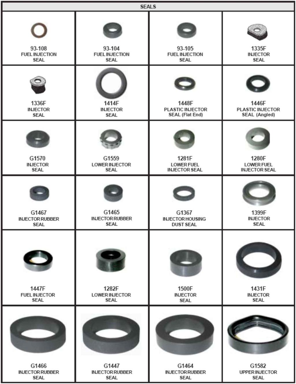
47 Operation Basics Final Coil and Flow Test This step is similar to the initial test, and provides the capability for the user to compare the values. Also the effectiveness of the cleaning is shown in the spray pattern and the volumetric displacement. Leak Test This step is the final step of the testing procedure. After the injectors have been cleaned and tested, it is imperative that the user checks for leaks. In this operation the machine applies fluid pressure to the injectors, without operating their electrical part. [note] - An injector may be operating correctly (spray and volume), nevertheless the injector should be free of leaks for at least 25 seconds. Spare Parts Once the injectors have been cleaned and tested, it is recommended the user repairs the injector further by replacing faulty accessories such as: Screen Filters, Pintle Caps etc. A sample kit of most commonly used injector accessory parts is provided initially with the machine. The user can order injector accessories through his/her locale distributor or by contacting MAGNETI MARELLI directly, using the Code provided in the Accessories list (Appendix D).
48 Advanced User When the user is familiar with the GS units [GS4/GS8 only] and would like to further take advantage of the machines capabilities, the following instruction are provided: The GS units have system defined simulation programs (combination of STRKs, ms & time) for every type of engine and type of injector, both different for testing and cleaning operations. These simulation programs have been carefully selected to better test and clean the fuel injectors. Nevertheless, an option for the advanced user to create his own simulation programs on a duplicate of the system defined programs, and storing those programs in memory. Once the user has selected Manual Operation Mode, any program operated is a user defined program and can be altered, following the directions below: 1. While a program is selected, but not operated, press the F button for more than The STRKs tab will start blinking, select the desired value using the Up/Down Arrows. 3. Press Left/Right Arrows to move to the ms tab. The ms tab will start blinking; select the desired value using the Up/Down Arrows. 4. Press Left/Right Arrows to move to the time tab. The time tab will start blinking; select the desired value using the Up/Down Arrows. 5. Press ENTER/START button to store the program, otherwise press CANCEL/STOP button to discard the changes made on this program and return to the programs menu.
49 Operation Basics [note] Sometimes the Strokes & milliseconds will not reach their maximum or minimum values because it is limited by the duty cycle operation. [Important] When a large amount of operation time is selected, the user should always be aware that a fluid overflow may occur, and should press the DRAIN button to continuously drain the tubes or reduce the amount of operation time.
50
51 Injector Types Chapter 6 Injector Types In this part of the operating manual the user will find useful information on various combinations of the provided adapters along with the fitting of the most common Top-feed and Side-feed injectors. The user can create his/her own combination of adapters and o-rings provided in the adapters kit in order to fit any type of injector on the test rail and hence the machine. [important] - The user must always check for leaks on the test rail before beginning the testing phase. Once the injectors have been fitted on the test rail, and the fluid hose is connected, the user should apply some pressure to the system and check for leaks.


52 Top-Feed Injectors DENSO, B-4 DENSO, B-4 HONDA, B-4 B-4 B-4 B-4 DENSO, B-4 B-4 B-4 B-4 B-4 B-4


53 Injector Types MITSUBISHI, B-4 KEIHIN, B-4, B-4 B-4 B-4 B-4 LUCAS, B-5 B-5 GM MULTEC, B-5 B-5 WEBER, B-5 B-5


54 B-5 B-5 LUCAS, B-5 B-5 B-5 B-5 B-5 B-5 WEBER SIEMENS, B- 5 HITACHI, B-5 B-5 B-5


55 Injector Types B-5 DELPHI, B-5 B-5 LUCAS / SIEMENS, B- 5 BOSCH (G-DI), B-5 MITSUBISHI (G-DI), B- 5 B-6 B-6 B-6 B-6 B-6 B-6


56 B-6 B-6 BOSCH, B-7 SIEMENS (G-DI), B-7


57 Injector Types Side-Feed Injectors GM, B-9 ROCHESTER, B-9 ROCHESTER GM,B-10 B-13 B-12 DENSO, B-11 BOSCH, B-19 BOSCH, B-19 BOSCH, B-19 BOSCH, B-19 BOSCH, B-19 B-18


58 B-14 B-15 B-15 B-15 NIPPONDENSO, B-15 B-15 JECS, B-15 B-17 B-17 B-14 B-14 NIPPON DENSO, B-14
59 Specifications Appendix A Specifications
60 Mains Voltage VAc V Mains Frequency Hz 50 / 60 Mains Fuse Ampere 5.0 A Mains Power Cord (CE Approved) 250 / 10 / V / A / mm Voltage/Amperage/Length 200 Power Consumption at Idle Operation Watt 15.0 Power Consumption at Average Operation Watt Power Consumption at Max [GS2 / GS4-8) Watt 200 / 320 Max. Filling Volume for Testing/Calibration Oil Tank lt. / gal. 3.7 / 0.98 [GS4/GS2] Max. Filling Volume for Testing/Calibration Oil Tank [GS8] lt. / gal. 4.6 / 1.2 Testing Filter Life Hours / Months 300 / 6 Testing Fluid Life Hours / Months 100 / 2 Max. System Build-Up Pressure Bar / Psi 8 / 115
61 Adapters and Mounting Appendix B Adapters and Mounting

62 Sealing an output port Figure 6-i, Test Rail Seal Illustration When the number of injectors to be tested is less than the openings in the fuel injector testing rail, then the user should use the adapters provided, to seal any unwanted rail openings. NOTE: For the Standard Test Rail & Adapters, the user should replace the parts: TESTRAIL-EX, ADJ-1, ADAPT-1 w/ o-rings, with TESTRAIL- STD.TOP.
63 Top-Feed Injector Fittings Adapters and Mounting
64 Top-Feed Injectors Fittings (Asian Top Feed) Figure 6-ii, Top-Feed Asian Type Fitting Illustration NOTE: For the Standard Test Rail & Adapters, the user should replace the parts: TESTRAIL-EX, ADAPT- H, ADJ-1, ADAPT-1 w/ o-rings, with TESTRAIL-STD.TOP.
65 Adapters and Mounting Top-Feed Injectors Fittings (European Top Type) Figure 6-iii, Top-Feed European Type Fitting Illustration NOTE: For the Standard Test Rail & Adapters, the user should replace the parts: TESTRAIL-EX, ADAPT- H, ADJ-1, ADAPT-1 w/ o-rings, with TESTRAIL-STD.TOP.
66 Top-Feed Injectors Fittings (Hose Type) Figure 6-iv, Top-Feed Hose Type Fitting Illustration NOTE: For the Standard Test Rail & Adapters, the user should replace the parts: TESTRAIL-EX, ADAPT- H, ADJ-1, ADAPT-1 w/ o-rings, with TESTRAIL-STD.TOP.

67 Adapters and Mounting Top-Feed Injectors Fittings (CIS Mechanical Type) Figure 6-v, Top-Feed Mechanical Type Fitting Illustration NOTE: For the Standard Test Rail & Adapters, the user should replace the parts: TESTRAIL-EX, ADAPT- H, ADJ-1, ADAPT-1 w/ o-rings, with TESTRAIL-STD.TOP.
68 Side-Feed Injector Fittings
69 Adapters and Mounting Side-Feed Injectors Fittings ( A Type, illustration 1) Figure 6-vi, Side-Feed Type (A) Fitting Illustration (1) NOTE: For the Standard Test Rail & Adapters, the user should replace the parts: TESTRAIL-EX, ADAPT- H, ADJ-1, ADAPT-1 w/ o-rings, with TESTRAIL-STD.TOP.
70 Side-Feed Injectors Fittings ( A Type, illustration 2) Figure 6-vii, Side-Feed Type (A) Fitting Illustration (2) NOTE: For the Standard Test Rail & Adapters, the user should replace the parts: TESTRAIL-EX, ADAPT- H, ADJ-1, ADAPT-1 w/ o-rings, with TESTRAIL-STD.TOP.

71 Adapters and Mounting Side-Feed Injectors Fittings ( A Type, illustration 3) Figure 6-viii, Side-Feed Type (A) Fitting Illustration (3) NOTE: For the Standard Test Rail & Adapters, the user should replace the parts: TESTRAIL-EX, ADAPT- H, ADJ-1, ADAPT-1 w/ o-rings, with TESTRAIL-STD.TOP.
72 Side-Feed Injectors Fittings ( A Type, illustration 4) Figure 6-ix, Side-Feed Type (A) Fitting Illustration (4) NOTE: For the Standard Test Rail & Adapters, the user should replace the parts: TESTRAIL-EX, ADAPT- H, ADJ-1, ADAPT-1 w/ o-rings, with TESTRAIL-STD.TOP.
73 Adapters and Mounting Side-Feed Injectors Fittings ( A Type, illustration 5) Figure 6-x, Side-Feed Type (A) Fitting Illustration (5) NOTE: For the Standard Test Rail & Adapters, the user should replace the parts: TESTRAIL-EX, ADAPT- H, ADJ-1, ADAPT-1 w/ o-rings, with TESTRAIL-STD.TOP.
74 Side-Feed Injectors Fittings ( B Type, illustration 1) Figure 6-xi, Side-Feed Type (B) Fitting Illustration (1) NOTE: For the Standard Test Rail & Adapters, the user should replace the parts: TESTRAIL-EX, ADAPT- H, ADJ-1, ADAPT-1 w/ o-rings, with TESTRAIL-STD.TOP.
75 Adapters and Mounting Side-Feed Injectors Fittings ( B Type, illustration 2) Figure 6-xii, Side-Feed Type (B) Fitting Illustration (2) NOTE: For the Standard Test Rail & Adapters, the user should replace the parts: TESTRAIL-EX, ADAPT- H, ADJ-1, ADAPT-1 w/ o-rings, with TESTRAIL-STD.TOP.
76 Side-Feed Injectors Fittings ( B Type, illustration 3) Figure 6-xiii, Side-Feed Type (B) Fitting Illustration (3) NOTE: For the Standard Test Rail & Adapters, the user should replace the parts: TESTRAIL-EX, ADAPT- H, ADJ-1, ADAPT-1 w/ o-rings, with TESTRAIL-STD.TOP.
77 Adapters and Mounting Side-Feed Injectors Fittings ( B Type, illustration 4) Figure 6-xiv, Side-Feed Type (B) Fitting Illustration (4) NOTE: For the Standard Test Rail & Adapters, the user should replace the parts: TESTRAIL-EX, ADAPT- H, ADJ-1, ADAPT-1 w/ o-rings, with TESTRAIL-STD.TOP.
78 Side-Feed Injectors Fittings ( B Type, illustration 5) Figure 6-xv, Side-Feed Type (B) Fitting Illustration (5) NOTE: For the Standard Test Rail & Adapters, the user should replace the parts: TESTRAIL-EX, ADAPT- H, ADJ-1, ADAPT-1 w/ o-rings, with TESTRAIL-STD.TOP.
79 Adapters and Mounting Side-Feed Injectors Fittings ( B Type, illustration 6) Figure 6-xvi, Side-Feed Type (B) Fitting Illustration (6) NOTE: For the Standard Test Rail & Adapters, the user should replace the parts: TESTRAIL-EX, ADAPT- H, ADJ-1, ADAPT-1 w/ o-rings, with TESTRAIL-STD.TOP.
80
81 Simulation Programs Appendix C Simulation Programs
82 TBI MPFI System Simulation for Testing Procedure STRK ms Time Operation sec sec sec. CONT. 10 sec. 400>> >> sec. 400>> >> sec sec. Idle Mode Middle RPM Mode (cruise) High RPM Mode Continuous Spraying Accelerate / Decelerate Rich mode Accelerate / Decelerate Normal Injector calibrating mode STRK ms Time Operation sec sec sec. CONT. 10 sec. 400>> >> sec. 400>> >> sec sec. Idle Mode Middle rpm Mode (cruise) High rpm Mode Continuous Spraying Accelerate / Decelerate Rich mode Accelerate / Decelerate Lean mode Injector calibrating mode
83 G-DI Simulation Programs STRK ms Time Operation sec sec sec. CONT. 10 sec. 300>> >> sec. 1000>> >> sec sec. Idle Mode Middle rpm Mode (cruise) High rpm Mode Continuous Spraying Accelerate / Decelerate Rich mode Accelerate / Decelerate Normal Injector calibrating mode
84 G-DI TBI MPFI System Simulation for Cleaning Procedure (Ultrasonic) STRK ms Time 500>> >>4.0 8 min 2000>> >>2.5 7 min 5000>> min min STRK ms Time 500>> >>4.0 5 min 500>> >>1.7 6 min min 1000>> >>2.5 8 min STRK ms Time min 500>> >>1.0 7 min min 2000>> >>1.1 8 min
85 Motorcycle MPFI Motorcycle System Simulation for Testing Procedure Simulation Programs STRK ms Time Operation sec sec sec. CONT. 10 sec. 500>> >> sec. 500>> >> sec sec. Idle Mode Middle RPM Mode (cruise) High RPM Mode Continuous Spraying Accelerate / Decelerate Rich mode Accelerate / Decelerate Normal Injector calibrating mode
86 Motorcycle MPFI Motorcycle System Simulation for Cleaning Procedure (Ultrasonic) STRK ms Time 1000>> >> min 1000>> >>2.5 7 min min 500>> >>1.0 8 min

87 Appendix D Accessories List

88 General Accessory List

89
90

91

92

93
94 Accessory List by Vehicle Model

95

96
97
98
99
100
101

102
103
104
105
106
107
108
109
110 Magneti Marelli Aftermarket Spółka z.o.o. Plac Pod Lipami 5, Katowice Tel.: + 48 (032) , Faks: + 48 (032) checkstar@magnetimarelli.com
Device Es 3 For Cleaning Engine, Valves, Dpf Filter. User s Manual
 Device Es 3 For Cleaning Engine, Valves, Dpf Filter User s Manual 007935095380 Magneti Marelli Aftermarket Spółka z.o.o. Plac Pod Lipami 5, 40-476 Katowice Tel.: + 48 (032) 6036107, Faks: + 48 (032) 603-61-08
Diesel Injector Test Bench CRU2i-3210 (without rinsing function) User s Manual
 User s Manual") Diesel Injector Test Bench CRU2i-3210 (without rinsing function) User s Manual 007935100750 007935095200 007935100320 ] Magneti Marelli Aftermarket Spółka z.o.o. Plac Pod Lipami 5, 40-476 Katowice Tel.:
Diesel Injector Test Bench CRU2i-3210 (without rinsing function) User s Manual 007935100750 007935095200 007935100320 ] Magneti Marelli Aftermarket Spółka z.o.o. Plac Pod Lipami 5, 40-476 Katowice Tel.:
Diesel Tech CRU.2. Owner s Manual
 Diesel Tech CRU.2 Owner s Manual 007935095200 Magneti Marelli Aftermarket Spółka z.o.o. Plac Pod Lipami 5, 40-476 Katowice Tel.: + 48 (032) 6036107, Faks: + 48 (032) 603-61-08 e-mail: checkstar@magnetimarelli.com
HYDRAULIC POWER PACK
 HYDRAULIC POWER PACK OPERATION & MAINTENANCE MANUAL Model 34484 Copyright 2012 by All rights reserved. No part of this publication may be copied, reproduced or transmitted in any form whatsoever without
Guangzhou Junliye Import&Export Co., Ltd. CW-6H Injector Diagnostic & Cleaning System. Operation manual
 CW-6H Injector Diagnostic & Cleaning System Operation manual OPERATING MANUAL INDEX 1. Technical Characteristics 2 2. Installation.3 3. Equipment Description..4 4. Control Board.6 5. Operation.9 I. MANUAL
AEROMOTIVE Part # L 4V Fuel Rails INSTALLATION INSTRUCTIONS
 AEROMOTIVE Part # 14130 5.0L 4V Fuel Rails INSTALLATION INSTRUCTIONS CAUTION: Installation of this product requires detailed knowledge of automotive systems and repair procedures. We recommend that this
AEROMOTIVE Part # Subaru Fuel Rails for Top Feed Injectors WRX & STI INSTALLATION INSTRUCTIONS
 AEROMOTIVE Part # 14134 Subaru Fuel Rails for Top Feed Injectors 02-14 WRX & 07-14 STI INSTALLATION INSTRUCTIONS CAUTION: Installation of this product requires detailed knowledge of automotive systems
AEROMOTIVE Part # GM LS1 Fuel Rails INSTALLATION INSTRUCTIONS
 AEROMOTIVE Part # 14106 GM LS1 Fuel Rails INSTALLATION INSTRUCTIONS CAUTION: Installation of this product requires detailed knowledge of automotive systems and repair procedures. We recommend that this
AEROMOTIVE Part # Ford 5.0 Liter INSTALLATION INSTRUCTIONS
 AEROMOTIVE Part # 14101 86-98 Ford 5.0 Liter INSTALLATION INSTRUCTIONS CAUTION: Installation of this product requires detailed knowledge of automotive systems and repair procedures. We recommend that this
AEROMOTIVE Part # Subaru Fuel Rails for Top Feed Injectors WRX & STI INSTALLATION INSTRUCTIONS
 AEROMOTIVE Part # 14135 Subaru Fuel Rails for Top Feed Injectors 02-14 WRX & 07-14 STI INSTALLATION INSTRUCTIONS CAUTION: Installation of this product requires detailed knowledge of automotive systems
AEROMOTIVE Part # INSTALLATION INSTRUCTIONS
 AEROMOTIVE Part # 14102 INSTALLATION INSTRUCTIONS CAUTION: Installation of this product requires detailed knowledge of automotive systems and repair procedures. We recommend that this installation be carried
AEROMOTIVE Part # L Ford F L Ford Expedition L Ford F-250 Super Duty INSTALLATION INSTRUCTIONS
 AEROMOTIVE Part # 14118 97-03 5.4L Ford F-150 97-02 5.4L Ford Expedition 98-03 5.4L Ford F-250 Super Duty INSTALLATION INSTRUCTIONS CAUTION: Installation of this product requires detailed knowledge of
AEROMOTIVE Part # Ford 5.4L Shelby GT500 Mustang INSTALLATION INSTRUCTIONS
 AEROMOTIVE Part # 14144 07 Ford 5.4L Shelby GT500 Mustang INSTALLATION INSTRUCTIONS CAUTION: Installation of this product requires detailed knowledge of automotive systems and repair procedures. We recommend
SB-300 Operator s Manual
 Test Equipment SB-300 Operator s Manual 20 Hand Held-Accuracy with a 40 Amp Load The SB-300 is a hand-held tester that is the auto industry s answer to portability in a professionally accurate battery
AEROMOTIVE Volkswagen 1.8T Fuel Rail Part # INSTALLATION INSTRUCTIONS
 AEROMOTIVE Volkswagen 1.8T Fuel Rail Part # 14163 INSTALLATION INSTRUCTIONS CAUTION: Installation of this product requires detailed knowledge of automotive systems and repair procedures. We recommend that
EXCELSIOR-HENDERSON MOTORCYCLE MANUFACTURING COMPANY 805 HANLON DRIVE BELLE PLAINE, MINNESOTA TELE: /FAX:
 All text, photographs, and illustrations in this handbook are based on the most current product information available at the time of publication. Product improvements or other changes may result in differences
AEROMOTIVE Part # L Ford F L Ford Expedition L Ford F-250 Super Duty INSTALLATION INSTRUCTIONS
 AEROMOTIVE Part # 14118 97-03 5.4L Ford F-150 97-02 5.4L Ford Expedition 98-03 5.4L Ford F-250 Super Duty INSTALLATION INSTRUCTIONS CAUTION: Installation of this product requires detailed knowledge of
EBS PRODUCTS
 EBS PRODUCTS WWW.ebsproducts.com OPERATIONS MANUAL EPG-1 Power Steering - Gear Oil Fluid Service Equipment #1000-0060 1-1-16 TABLE OF CONTENTS I. SAFETY INFORMATION... 2 1.01 IMPORTANT SAFETY NOTICE...
AEROMOTIVE Part # Ford 5.4L GT500 Shelby Mustang Fuel Rail Kit INSTALLATION INSTRUCTIONS
 AEROMOTIVE Part # 14145 07 Ford 5.4L GT500 Shelby Mustang Fuel Rail Kit INSTALLATION INSTRUCTIONS CAUTION: Installation of this product requires detailed knowledge of automotive systems and repair procedures.
AEROMOTIVE Part # C5 Corvette Fuel Rail Kit INSTALLATION INSTRUCTIONS
 AEROMOTIVE Part # 14128 99-04 C5 Corvette Fuel Rail Kit INSTALLATION INSTRUCTIONS CAUTION: Installation of this product requires detailed knowledge of automotive systems and repair procedures. We recommend
AEROMOTIVE Part # Subaru STI Fuel Rail Kit INSTALLATION INSTRUCTIONS
 AEROMOTIVE Part # 14137 04-06 Subaru STI Fuel Rail Kit INSTALLATION INSTRUCTIONS CAUTION: Installation of this product requires detailed knowledge of automotive systems and repair procedures. We recommend
EBS PRODUCTS
 ! EBS PRODUCTS WWW.ebsproducts.com OPERATIONS MANUAL EDS-1 Dip Stick Fluid Exchange Equipment #1000-0075 1-1-16 TABLE OF CONTENTS I. SAFETY INFORMATION... 2 1.01 IMPORTANT SAFETY NOTICE... 2 1.02 IMPORTANT
OPERATION AND MAINTENANCE
 Table of Contents GENERAL INFORMATION INTRODUCTION... 1 Operating Specifications... 1 FEATURES... 1 SAFETY PRECAUTIONS... 2 SET-UP... 2 OPERATION AND MAINTENANCE TESTING AN IGNITION MODULE OR IGNITION
AEROMOTIVE Part # /2 4.6L SOHC Ford Fuel Rail Kit INSTALLATION INSTRUCTIONS
 AEROMOTIVE Part # 14125 96-98 1/2 4.6L SOHC Ford Fuel Rail Kit INSTALLATION INSTRUCTIONS CAUTION: Installation of this product requires detailed knowledge of automotive systems and repair procedures. We
World Leaders in Diesel Fuel Injection Test Equipment. IFT-c. Injector Function Tester Controller. Operating and Servicing Manual
 World Leaders in Diesel Fuel Injection Test Equipment. IFT-c Injector Function Tester Controller Operating and Servicing Manual HL048 (EN) Issue 4, H1852, August 2011 HARTRIDGE LIMITED IFT-c Operating
Owner s Manual & Safety Instructions
 Owner s Manual & Safety Instructions Save This Manual Keep this manual for the safety warnings and precautions, assembly, operating, inspection, maintenance and cleaning procedures. Write the product s
AEROMOTIVE Part # / L SOHC Ford Fuel Rail Kit INSTALLATION INSTRUCTIONS
 AEROMOTIVE Part # 14119 98 1/2-04 4.6L SOHC Ford Fuel Rail Kit INSTALLATION INSTRUCTIONS CAUTION: Installation of this product requires detailed knowledge of automotive systems and repair procedures. We
AEROMOTIVE Part # Subaru STI Fuel Rails INSTALLATION INSTRUCTIONS
 AEROMOTIVE Part # 14136 04-06 Subaru STI Fuel Rails INSTALLATION INSTRUCTIONS CAUTION: Installation of this product requires detailed knowledge of automotive systems and repair procedures. We recommend
Fuel System Service & Diagnostic Equipment OPERATOR S MANUAL MCS 245
 Fuel System Service & Diagnostic Equipment OPERATOR S MANUAL MCS 245 Table of Contents Introduction...3 Overview...4 System Features and Functions...5 System Features and Functions... Hose and Battery
Unit MC07K Knowledge of Diagnosis and Rectification of Motorcycle Engine Faults
 Assessment Requirements Unit MC07K Knowledge of Diagnosis and Rectification of Motorcycle Engine Faults Content: Single cylinder and multi-cylinder fuel injection systems a. The operation and construction
Use & Care Guide. If you have any problems or questions, visit us at For Commercial Use Only
 Use & Care Guide If you have any problems or questions, visit us at www.spectradtg.com For Commercial Use Only 1 Table of Contents 1. IMPORTANT SAFETY INSTRUCTIONS... 3 2. PARTS AND FEATURES... 4 3. REQUIRED
Power Filter Kit PART# - RS
 Power Filter Kit PART# - RS13100-1 We strongly recommend the use of a service manual to familiarize yourself with the various components and procedures involved with this installation. Please note that
EVAP system, servicing
 Page 1 of 65 20-130 EVAP system, servicing EVAP system components 1 - Cap nut 10 Nm 2 - Cover 3 - Stud For EVAP canister 15 Nm 4 - Sealing piece 5 - Bleed line To EVAP canister purge regulator valve -
Owner s Manual Supplement. Liquefied Petroleum Gas (LPG) Fuel System for 1998 GM Medium Duty Chassis (C-60/C-70) with 6.0L and 7.
 Fuel System for 1998 GM Medium Duty Chassis (C-60/C-70) with 6.0L and 7.") Owner s Manual Supplement Liquefied Petroleum Gas (LPG) Fuel System for 1998 GM Medium Duty Chassis (C-60/C-70) with 6.0L and 7.0L V8 OWNERS MANUAL SUPPLEMENT Table of Contents Refueling Your Vehicle...1
Owner s Manual Supplement Liquefied Petroleum Gas (LPG) Fuel System for 1998 GM Medium Duty Chassis (C-60/C-70) with 6.0L and 7.0L V8 OWNERS MANUAL SUPPLEMENT Table of Contents Refueling Your Vehicle...1
S&S. Installation Instructions: S&S Billet Air Cleaner Kit PN for Victory Motorcycles. Instruction IMPORTANT NOTICE:
 Instruction 106-1330 06-23-10 Copyright 2008, 2009, & 2010 by S&S Cycle, Inc. All rights reserved. Printed in the U.S.A. S&S Cycle, Inc. 14025 Cty Hwy G PO Box 215 Viola, Wisconsin 54664 Phone: 608-627-1497
EBS PRODUCTS
 ! EBS Coolant Flush EBS PRODUCTS www.ebsproducts.com OPERATIONS MANUAL EC-1 Coolant Flush #1000-0070 1-1-16! 1 EBS Products Westminster, CA 92683 Phone: 877-955-0515 Fax: 714-896-6711 E-mail: sales@ebsproducts.com
AEROMOTIVE Part # C5 Corvette Fuel Rail / Regulator Kit INSTALLATION INSTRUCTIONS
 AEROMOTIVE Part # 14129 99-04 C5 Corvette Fuel Rail / Regulator Kit INSTALLATION INSTRUCTIONS CAUTION: Installation of this product requires detailed knowledge of automotive systems and repair procedures.
OPERATION MANUAL ESX-2
 OPERATION MANUAL ESX-2 Fuel System Cleaner RTI Technologies, Inc 4075 East Market St. York, PA 17402 800-468-2321 www.rtitech.com Manual P/N 035-80873-00 (Rev A) Table of Contents Component Description...2
Operator s Manual Portable Wood Chip Moisture Tester ENGLISH
 Operator s Manual Portable Wood Chip Moisture Tester ENGLISH DOCU-M0137 0212 Introduction THANK YOU for purchasing a Wood Chip Moisture Tester. READ THIS MANUAL carefully to learn how to operate and service
INSTALLATION INSTRUCTIONS
 APPLICATIONS: 2000-`02 GPR1200R; 1999-`00 XL1200Ltd.; 2001-`03 XLT1200 PARTS LISTING PART# QTY DESCRIPTION N/A 1 Stinger 3 Billet Flange N/A 1 Stinger 3 Head Pipe N/A 1 Stinger 2/3 Tail Pipe N/A 6 8MM
Chapter 4 Part D: Fuel and exhaust systems - Magneti Marelli injection
 4D 1 Chapter 4 Part D: Fuel and exhaust systems - Magneti Marelli injection Contents Accelerator cable - removal and..................... 11 Air cleaner element - renewal..............................
High Pressure Leak Diagnostics System Part No & NA USER MANUAL LEAK DETECTION SERVICE
 Cool Smoke HP High Pressure Leak Diagnostics System Part No. 500-0150 & 500-0150NA USER MANUAL LEAK DETECTION SERVICE 1324 Blundell Rd. Mississauga ON Tel. 905.615.8620 Fax. 905.615.9745 Introduction Congratulations!
Active Controlled Cooling System
 Active Controlled Cooling System April 2011 3267 Progress Dr Orlando, FL 32826 www.apecor.com Preliminary www.apecor.com Table of Contents General Information... 3 Safety... 3 Introduction... 3 What s
FlexChem Model 404 Rotating Oven
 www.scigene.com FlexChem Model 404 Rotating Oven USER MANUAL Cat. #1052-20-1, 1052-20-2, 1052-22-1 & 1052-22-2 FOR RESEARCH USE ONLY Not for Use in Diagnostic Procedures SciGene 306 Potrero Ave, Sunnyvale,
Hybex Microsample Incubator
 www.scigene.com Hybex Microsample Incubator USER MANUAL Cat. #1057-30-0, 1057-30-2 FOR RESEARCH USE ONLY 470 Lakeside Dr, Ste F, Sunnyvale, CA 94085-4720 USA Tel 408-733-7337 Fax 408-733-7336 techserv@scigene.com
INSTRUCTION MANUAL. Smart Pressure. Variable Pressure Diagnostic Smoke Machine. with UltraTraceUV Non-Contaminant Dye Solution Model No.
 INSTRUCTION MANUAL Smart Pressure Variable Pressure Diagnostic Smoke Machine with UltraTraceUV Non-Contaminant Dye Solution Model No. WV711 Leak Detection Systems for the Professional Technician USA Canada
Instruction Model 18537
 Instruction 738-556 Model 18537 LIMITED WARRANTY H. D. Hudson Manufacturing Company warrants to the original purchaser only that this product will continue to function as intended if used in accordance
5. FUEL SYSTEM 5-0 FUEL SYSTEM UXV 500
 5 FUEL SYSTEM 5 SERVICE INFORMATION------------------------------------------------ 5-02 TROUBLESHOOTING----------------------------------------------------- 5-03 FUEL TANK -----------------------------------------------------------------
CAUTION: CAREFULLY READ INSTRUCTIONS BEFORE PROCEEDING
 Daytona Sensors LLC Engine Controls and Instrumentation Systems Installation Instructions for Wide-Band Exhaust Gas Oxygen Sensor Interface CAUTION: CAREFULLY READ INSTRUCTIONS BEFORE PROCEEDING OVERVIEW
PHASERS. Operating and Instruction Manual. a n d A C C E S S O R I E S
 VOLTMETERS PHASERS a n d A C C E S S O R I E S Operating and Instruction Manual HD ELECTRIC COMPANY 1 4 7 5 L A K E S I D E D R I V E WA U K E G A N, I L L I N O I S 6 0 0 8 5 U. S. A. PHONE 847.473.4980
5. FUEL SYSTEM FUEL SYSTEM 5-0
 5 FUEL SYSTEM 5-0 SERVICE INFORMATION GENERAL INSTRUCTIONS SERVICE INFORMATION...5-1 CARBURETOR INSTALLATION...5-9 TROUBLESHOOTING...5-1 PILOT SCREW ADJUSTMENT...5-10 CARBURETOR REMOVAL...5-2 AUTO BYSTARTER...5-3
INSTRUCTION MANUAL_1219_ENGLISH SUPER ELF X3. Operating Instructions for DORNIER looms. Robustness Reliability Quality Productivity Versatility
 INSTRUCTION MANUAL_1219_ENGLISH SUPER ELF X3 Operating Instructions for DORNIER looms Robustness Reliability Quality Productivity Versatility WARNING! - Condensation could form on the Weft Feeder when
Fuel Injection System
 7. Fuel Injection System XCITING 400i Fuel Injection System This chapter covers the location and servicing of the fuel system components for the KYMCO XCITING 400i. Air box... 7-2~7-5 Fuel Tank... 7-6~7-10
Classic Instruments. Installation Manual
 Classic Instruments Installation Manual TABLE OF CONTENTS Welcome from the Team at Classic Instruments! 3 Mounting Gauges 4 4 Speedometer Wiring 5 4 Speedometer Wiring Diagram 5 16 Pulse Signal Generator
MoistureMatch A next generation grain tester
 MoistureMatch A next generation grain tester A next generation moisture tester incorporating new and unique technology. Finally, a portable tester that will more accurately match and track with the commercial
INW Panel Meter Reading an INW PT12 Sensor
 INW Panel Meter Reading an INW PT12 Sensor PROUDLY MADE IN THE USA ISO 9001:2008 Certified Company Table of Contents Introduction...5 What is an INW Panel Meter for an INW PT12 Smart Sensor?...5 Initial
G8 Portable Fuel Transfer Pump Owner s Manual
 G8 Portable Fuel Transfer Pump Owner s Manual GENERAL INFORMATION This pump is designed for use only with gasoline (up to 15% alcohol blends such as E15), diesel fuel (up to 20% biodiesel blends such as
ECLIPSE Laundry Dispenser Controller
 ECLIPSE Laundry Dispenser Controller Reference Manual Programming and Operation Online and downloadable Product Manuals and Quick Start Guides are available at www.hydrosystemsco.com Please check online
FUEL INJECTION SYSTEM - MULTI-POINT
 FUEL INJECTION SYSTEM - MULTI-POINT 1988 Jeep Cherokee 1988 Electronic Fuel Injection JEEP MULTI-POINT 4.0L Cherokee, Comanche, Wagoneer DESCRIPTION The Multi-Point Electronic Fuel Injection (EFI) system
QUICK START GUIDE 199R10546
 QUICK START GUIDE 199R10546 1.0 Overview This contains detailed information on how to use Holley EFI software and perform tuning that is included within the software itself. Once you load the software,
BBT-205. For 12-volt automotive starting batteries and starting/charging systems INSTRUCTION MANUAL
 For 12-volt automotive starting batteries and starting/charging systems INSTRUCTION MANUAL Blank page Contents Registering Your tester... 5 Caution... 6 Capabilities... 6 Display and Keypad... 6 Preparations
Swing Arm Magnifying Lamp
 Owner s Manual & Safety Instructions Save This Manual Keep this manual for the safety warnings and precautions, assembly, operating, inspection, maintenance and cleaning procedures. Write the product s
Guide. Safety. Dear Sirs, Firstly, thank you for selecting Fuel Injector Tester & Cleaner.
 Safety Guide Dear Sirs, Firstly, thank you for selecting Fuel Injector Tester & Cleaner. You have possessed a guaranteed assistant, the careful design will offer you the long-term trustworthy service.
WEBER CARBURETOR TROUBLESHOOTING GUIDE
 This guide is to help pinpoint problems by diagnosing engine symptoms associated with specific vehicle operating conditions. The chart will guide you step by step to help correct these problems. For successful
User s Guide For Control Pressure Gauge
 User s Guide For Note: The fuel system should be under pressure even when the car is off. ALWAYS follow these precautions: 1. Always wear safety glasses. 2. When the fuel lines are first loosened about
MOTORCYCLE / ATV 2010 Distributor s Warranty
 MOTORCYCLE / ATV 2010 Distributor s Warranty Reorder Part No.:00X38-M10-W000 RG.30000.2009.03.10 V.I.N. DATE OF SALE SELLING DEALER DISTRIBUTOR S WARRANTY Honda Canada Inc., for and on behalf of Honda
InjectorServiceKitCatalog
 InjectorServiceKitCatalog GREENTUNE AUTOMOTIVE PRODUCTS LLC is a leading Distribution company specializing in automotive & light truck replacement parts and ASNU gasoline fuel injector diagnostic & cleaning
Ford Mustang. Installation Manual
 1965 1966 Ford Mustang Installation Manual TABLE OF CONTENTS Welcome from the Team at Classic Instruments! 3 Mounting Gauges in New Bezel 4 3 3/8 Speedometer Wiring 6 3 3/8 Speedometer Wiring Diagram 6
AEROMOTIVE Part # & ½ L DOHC Return Style Fuel System Kit INSTALLATION INSTRUCTIONS
 AEROMOTIVE Part # 17145 & 17146 98 ½-04 4.6L DOHC Return Style Fuel System Kit INSTALLATION INSTRUCTIONS CAUTION: Installation of this product requires detailed knowledge of automotive systems and repair
J1939 POWERCELL Setup and Configuration Guide Universal Switch Interface
 Table of Contents J1939 POWERCELL Setup and Configuration Guide Universal Switch Interface Overview... 2 Warnings... 3 J1939 POWERCELL Technical Details... 4 POWERCELL Installation Steps... 5 Mounting
PolyStat Immersion Circulators
 PolyStat Immersion Circulators Manual P/N U00988 Rev. 06/09/08 Instruction and Operation Manual PolyStat Immersion Circulator Table of Contents Preface Safety Compliance... 2 Unpacking... 2 Warranty...
MCS 352 DUAL SYSTEM FOR Gasoline (Petrol) and Diesel Engines
 and Diesel Engines") MCS 352 DUAL SYSTEM FOR Gasoline (Petrol) and Diesel Engines OPERATORS MANUAL MOTORVAC TECHNOLOGIES INC. MCS352 PN 200-0352 Rev NC 2005 Table of Contents Introduction... iii Overview... v System Features
MCS 352 DUAL SYSTEM FOR Gasoline (Petrol) and Diesel Engines OPERATORS MANUAL MOTORVAC TECHNOLOGIES INC. MCS352 PN 200-0352 Rev NC 2005 Table of Contents Introduction... iii Overview... v System Features
1999 Oldsmobile Truck Bravada V6-4.3L VIN W
 1 of 6 8/24/2015 9:53 PM 1999 Oldsmobile Truck Bravada V6-4.3L VIN W Vehicle» Powertrain Management» Fuel Delivery and Air Induction» Fuel Meter Body» Service and Repair CLEANING AND INSPECTION PROCEDURE
PIERBURG. Carburetor: 2E3
 PIERBURG Carburetor: 2E3 1 fast idle adjusting screw 2 throttle lever 3 fuel mixture adjusting screw 4 main body 5 idle cut off valve 6 stop screw 7 accelerator pump cover 8 diaphragm 9 spring 10 valve
Automatic Emergency Light
 Automatic Emergency Light Item 38013 Read this material before using this product. Failure to do so can result in serious injury. Save this manual. When unpacking, make sure that the product is intact
Automotive Fuel and Emissions Control Systems 4/E
 Automotive Fuel and Emissions Control Systems 4/E Opening Your Class KEY ELEMENT Introduce Content Motivate Learners State the learning objectives for the chapter or course you are about to cover and explain
IMPORTANT SAFETY INSTRUCTIONS
 Table of Contents Safety... 2 Specifications... 3 Functions... 4 Operation... 5 Maintenance... 7 Warranty... 7 SAFETY SPECIFICATIONS OPERATION MAINTENANCE WARNING SYMBOLS AND DEFINITIONS This is the safety
STARDEX 0303, 0304, 0305, 0306, 0402, STARDEX Master Ultima. STARDEX Dimas. STARDEX Dimas Ultima
 New software STARDEX SISU user manual STARDEX 0303, 0304, 0305, 0306, 0402, 0403 STARDEX Master Ultima STARDEX Dimas STARDEX Dimas Ultima 2017 STARDEX GUI NEW FEATURES ENG Foreword For more than 15 years,
Document Library TS Data Sheet Universal Fuel System Cleaner. Data Sheet. Public
 Document Library TS Data Sheet 08955 Public Rev:1 Effective: 11/03/2000 Status: Active Universal Fuel System Cleaner Data Sheet 3M Part No.(s) 3M Part Descriptor(s) 08955 Professional Formula Universal
IMPORTANT INFORMATION
 Table of Contents IMPORTANT INFORMATION Section 1B - Maintenance MAINTENANCE 1 B Specifications........................... 1B-1 Special Tools........................... 1B-2 Mercury/Quicksilver Lubricants
USER GUIDE 1 USER GUIDE
 USER GUIDE 1 USER GUIDE 1 TABLE OF CONTENTS IN THE BOX...3 NAVIGATING THE MENUS...3 MENU LAYOUT...3 UPDATE YOUR PROGRAMMER...4 CONNECT WITH THE MOTORCYCLE...5 TUNE YOUR MOTORCYCLE...6 ADDITIONAL FEATURES...8
25 GALLON PORTABLE OIL LIFT
 25 GALLON PORTABLE OIL LIFT Model 92859 SET UP AND OPERATING INSTRUCTIONS Diagrams within this manual may not be drawn proportionally. Due to continuing improvements, actual product may differ slightly
MOTORCYCLE / ATV DISTRIBUTOR S WARRANTY
 MOTORCYCLE / ATV 2014> Distributor s Warranty DISTRIBUTOR S WARRANTY Honda Canada Inc., for and on behalf of Honda Motor Co. Ltd., Tokyo, Japan, gives the following written warranties on each new Honda
12. CARBURETOR 12-0 CARBURETOR VITALITY 50
 12 12 CARBURETOR SERVICE INFORMATION (2-STROKE)... 12-2 SERVICE INFORMATION (4-STROKE)... 12-3 THROTTLE VALVE (2-STROKE)... 12-5 CARBURETOR (2-STROKE)... 12-7 AIR SCREW ADJUSTMENT (2-STROKE)... 12-13 REED
7649A FUEL INJECTOR CLEANING SPECIALTY TOOLS USER MANUAL & REPLACEMENT PARTS LIST
 7649A FUEL INJECTOR CLEANING SPECIALTY TOOLS USER MANUAL & REPLACEMENT PARTS LIST Safety Precautions WARNING: The following safety precautions must be carefully observed to reduce the risk of fire and
FOR SERVICE SEND TO: AUTO METER PRODUCTS, INC. 413 W. Elm St., Sycamore, IL USA (815) us at
 us at") 2650-887F INSTALLATION INSTRUCTIONS 5 single channel ultimate tach COPYRIGHT PATENT 5 4 6 3 PENDING 7 8 PLAYBACK 9 2 0 1 AUTO METER PRODUCTS, INC. SYCAMORE, IL USA MADE R P M X1000 IN USA ENTER START PAUSE
2650-887F INSTALLATION INSTRUCTIONS 5 single channel ultimate tach COPYRIGHT PATENT 5 4 6 3 PENDING 7 8 PLAYBACK 9 2 0 1 AUTO METER PRODUCTS, INC. SYCAMORE, IL USA MADE R P M X1000 IN USA ENTER START PAUSE
Model 700 Microarray Oven
 www.scigene.com Model 700 Microarray Oven USER MANUAL Cat. #1070-00-1, 1070-00-2 FOR RESEARCH USE ONLY Not for Use in Diagnostic Procedures SciGene 306 Potrero Ave, Sunnyvale, CA 94085 USA 408-733-7337
DUAL PURPOSE DIAGNOSTIC LEAK DETECTOR
 OPERATION MANUAL DUAL PURPOSE DIAGNOSTIC LEAK DETECTOR P/N 95-030 NIS -800-662-200 nissantechmate.com CONTENTS Specifications / Warranty... Functions...2-3 Accessories... 4 Set-Up... 5 Adaptor Installation...
Please begin by checking that you have received all of the parts that come with your kit.
 1 INSTRUCTIONS EZ-EFI 30402-FK In-Line Fuel Kit Thank you for choosing products; we are proud to be your manufacturer of choice. Please read this instruction sheet carefully before beginning installation,
CP9125 OBDII PocketScan Code Reader
 CP9125 OBDII PocketScan Code Reader User guide Safety Precautions.... 4 Signal Words and Symbols.... 4 Important Safety Messages.... 5 Tool Parts.... 6 PocketScan Code Reader Features... 6 Read Codes...
ATD Gallon Pressurized Oil Drain Owner s Manual
 ATD-5203 30 Gallon Pressurized Oil Drain Owner s Manual TECHNICAL SPECIFICATIONS Model: ATD-5203 Capacity: 30 Gallon Drain Funnel Working Height: 47.25 to 70.5 Drain Funnel Diameter: 15.75 Plastic Tray:
INSTRUCTION and OPERATIONS MANUAL. for
 INSTRUCTION and OPERATIONS MANUAL for SPEED-O-CALIBRATOR Locomotive Speedometer Calibrator Unit MODEL NUMBER 16470-00 CAUTION Be sure to read and become thoroughly familiar with the entire contents of
Knowledge of diagnosis and rectification of light vehicle engine faults
 Unit 157 Knowledge of diagnosis and rectification of light vehicle engine faults UAN: F/601/3733 Level: No Level Credit value: 6 GLH: 45 Relationship to NOS: This unit is linked to LV07 Diagnose and Rectify
F 167/94 07/ GM-
 5.956 172 F 167/94 07/95 1750 GM- 1750 GM 3 4 2 5 1 16 7 6 8 9 10 15 11 14 12 13 9 1. Unit Start-Up 1750 GM 1 Spray lance with pressure control 2 Spray lance extension 3 Hand gun 4 Safety catch 5 Handle
Knowledge of Diagnosis and Rectification of Light Vehicle Engine Faults
 Unit 157 Knowledge of Diagnosis and Rectification of Light Vehicle Engine Faults UAN: F/601/3733 Level: Level 3 Credit value: 6 GLH: 45 Relationship to NOS: This unit is linked to LV07 Diagnose and Rectify
Fuel System Diagnosis
 Page 1 of 9 1999 Chevrolet Express Express, Savana (VIN G) Service Manual Engine Engine Controls - 5.0L and 5.7L Diagnostic Information and Procedures Document ID: 412957 Fuel System Diagnosis Circuit
2.8 Liter VR6 2V Fuel Injection & Ignition, Engine Code(s): AAA m.y
: AAA m.y") 2.8 Liter VR6 2V Fuel Injection & Ignition, Engine Code(s): AAA m.y. 1996-1997 01 - On Board Diagnostic (OBD) On Board Diagnostic (OBD II) Malfunction Indicator Lamp (MIL) On Board Diagnostic (OBD II),
2.8 Liter VR6 2V Fuel Injection & Ignition, Engine Code(s): AAA m.y. 1996-1997 01 - On Board Diagnostic (OBD) On Board Diagnostic (OBD II) Malfunction Indicator Lamp (MIL) On Board Diagnostic (OBD II),
AEROMOTIVE Part # & Mustang Stealth Fuel Tank w/fuel pump INSTALLATION INSTRUCTIONS
 AEROMOTIVE Part # 18685 &18686 86-98.5 Mustang Stealth Fuel Tank w/fuel pump INSTALLATION INSTRUCTIONS CAUTION: Installation of this product requires detailed knowledge of automotive systems and repair
GPS AutoSteer System Installation Manual
 GPS AutoSteer System Installation Manual Supported Vehicles Case IH Combines 7010 7120 8010 8120 AFX 8010 9120 PN: 602-0283-01-A LEGAL DISCLAIMER Note: Read and follow ALL instructions in this manual carefully
EMISSION CONTROL WARRANTY STATEMENT
 EMISSION CONTROL WARRANTY STATEMENT YOUR WARRANTY RIGHTS AND OBLIGATIONS The California Air Resources Board, U.S. EPA and Zenith Power Products LLC (ZPP) are pleased to explain the emission control system