INSTRUCTION MANUAL. Smart Pressure. Variable Pressure Diagnostic Smoke Machine. with UltraTraceUV Non-Contaminant Dye Solution Model No.
|
|
|
- Charleen Pearson
- 5 years ago
- Views:
Transcription


1 INSTRUCTION MANUAL Smart Pressure Variable Pressure Diagnostic Smoke Machine with UltraTraceUV Non-Contaminant Dye Solution Model No. WV711 Leak Detection Systems for the Professional Technician USA Canada Euro Patents: 6,392,227 6,439,031 6,526,808 2,279,147 2,394,911 1,384,984 Other Patents Pending
2 ii


 UV light range.")
3 Caution and Usage Tips DO NOT use this Tester in the fuel evaporative (EVAP) system, due to its high pressure capabilities. DO NOT connect the Tester in such a way where its high pressure will be introduced into the engine s crank case system, or oil seals may be damaged ALWAYS use Tester with vehicle engine turned <OFF>. Use this equipment in the manner specified by the manufacturer. Follow common sense safety precautions. Connect Tester s black cable to chassis ground, when using Battery Cables WVA-40. Use UltraTraceUV Smoke Solution No. WV0712UV in Tester. Using a non-approved solution can cause damage to vehicles being tested and may cause personal injury. Do not leave Tester s hose or power cables connected to the vehicle if tests are not being performed. Do not perform test near source of spark or ignition. Wear appropriate eye protection. Wear yellow glasses supplied when using ultraviolet light. When using alternate source of UV light, use light that includes 405 nanometer (nm) UV light range. Air or gas pressure supplied to Tester can be between 3.4 to 12 bar (50 ~ 175 PSIG). Tester can be used with workshop compressed air or any inert gas. When testing an engine's boosted intake or exhaust system for leaks, it is best if the engine is cold. Small leaks may be sealed due to thermal expansion. If using a gas other than workshop air (such as nitrogen), disconnect the nitrogen from the Tester after every use. An internal calibration bleed system in the Tester will cause the nitrogen to slowly bleed off when the Tester is not in use. Height Length Width Weight Shipping weight Power supply Solution Max. Volume Specifications 14.5 in. (36.8 cm) in. (34.9 cm) 10 in. (25.4 cm) 20 lb. (9 kg) 25 lb. (11.3 kg) volts DC (or V AC with Optional WVA-080) 24 oz. (710 ml) Inlet gas source Inlet pressure Output pressure Output volume Smoke output line Power supply line Power consumption Meets ASME Standards: for Division 1 Pressure Vessel Code and Pressure Relief Valve Compressed air or inert gas 50 to 175 PSIG (3.4 to 12 bar) 3 to 43.5 PSIG (0.21 to 3 bar) 0-15 liters per minute 15 feet (4.6 m) 15 feet (4.6 m) 5-15 amps. This product contains STAR licensed technology, inside. iii
4 Contents Caution & Usage Tips Specifications Included Accessories Optional Accessories Product Overview Initial Setup Quick Start Guide Basic Test Procedure Leak Samples LED Display Codes Programming Remote Control Fob Programming PSI or BAR Pressure Setting Warranty iii iii Thank You and Congratulations! Your Smart Pressure leak detector, which incorporates STAR Diagnostic Smoke Technology inside, is the simplest and quickest way to find many vehicle system leaks. Smoke vapor-generating leak detectors containing STAR Technology are the only leak detectors in the world internationally-mandated by automakers (OEMs). Unlike conventional high pressure smoke machines, Smart Pressure technology produces the densest visible smoke vapor over the Tester s entire operating pressure range. Smart Pressure technology software prevents thinning of smoke density that occurs when conventional analog units are set at high pressure. A denser smoke vapor means it's easier to see at leak points. And setting the test pressure is fully automatic and could not be simpler. At high pressure, the smoke vapor escaping a leak can be very difficult to see with a conventional smoke machine. However, this Smart Pressure leak detector contains UltraTraceUV smoke-producing solution, which is an essential feature for high pressure leak testing. The vaporized UltraTraceUV solution deposits a trace dye at the exact location of the leak(s). You simply cannot find all high pressure leaks without it! The patented technology inside your Tester, including the UltraTraceUV, was designed in collaboration with major OEMs, in order to establish a contaminant-free standard for leak detection. It is designed to be safe for vehicle systems and will not void factory warranties. iv

. (Part No.")
 white light, for easier smoke location and ultraviolet (UV) light to highlight the fluorescent dye")
 Plug-in Battery Cables: (WVRP-40) connects to WV711 and 12VDC battery.")

5 Included Accessories UltraTraceUV : (WV0712UV) this patented solution is the only Automaker-Mandated smoke-producing solution in the world. The solution s chemistry will not damage vehicle components and contains a special contaminant-free dye that deposits at the exact location of a leak. Each bottle will perform approximately 150 test cycles. (12 oz. / 355 ml). (Part No. is for one bottle, two bottles included with Tester). Combination Light: (WVA-065) white light, for easier smoke location and ultraviolet (UV) light to highlight the fluorescent dye deposited at the exact location of a leak. Also has laser pointer to view laser reflections on exiting vapor. Remote Control: (WVA-073) Plug-in Battery Cables: (WVRP-40) connects to WV711 and 12VDC battery. Supply Hose Male Fitting: (sourced locally) it is the same fitting as is attached to optional adapter kit WVA-091. It is the matching coupler to the female connection at the end of the WV711 Tester s smoke supply hose. It can be used as a universal fitting to convert to any adapter required to access a test system. Air/Gas Fitting: (sourced locally) two are supplied. The automotive style fitting is already installed on the air/gas inlet side of the WV711 Tester. The spare fitting is an industrial fitting. 1
: sizes 35mm to 105mm, in 5mm increments.")


 regulator connects directly onto nitrogen cylinder and")

6 Optional Accessories Turbo Adapter Set, with through hole: (WVA-091): sizes 35mm to 105mm, in 5mm increments. Adapter plug: (WVA-095): used to convert a WVA-091 through hole adapter into a plug. It is included in the WVA-091 set. VW Turbo Adapter: (WVA-092) Power Converter (WVA-080) connects to smoke tester and grounded wall power outlet, to avoid using the vehicle battery as a power source. AC input: V AC/5A 50/60Hz DC output: 12V 25A Nitrogen Tank Pressure Regulator: (WVA-051) preset 100 PSIG (6.9 bar) regulator connects directly onto nitrogen cylinder and coiled hose WVA-041, in the event test specifications requires nitrogen instead of compressed air. ¼ x 25 Coiled Nitrogen Hose: (WVA-041) connects directly onto nitrogen tank pressure regulator WVA-051 and WV711 Tester. 2
 Basic Instructions Remote Control Fob (Red button controls ON/OFF.")
 with filter drain port on underside of Tester; keeps tester and vehicle clean by")


7 Product Overview Scratch-Resistant Housing Smoke Solution Dipstick Air/Gas Inlet Power Cables Control Panel (See panel on next page) Basic Instructions Remote Control Fob (Red button controls ON/OFF. Gray button control MODE) Power Plug Smoke Supply Hose Filter Drain Port Underside of Tester Water Separator / Filter (inside tester) with filter drain port on underside of Tester; keeps tester and vehicle clean by automatically draining water and contaminants from workshop air compressor. It is normal to occasionally see drainage of fluid from this port. But excessive drainage indicates your air compressor requires draining and/or a filter system. IMPORTANT NOTE: In order for the moisture and contaminants that collect in the filter bowl of the Tester to drain, the air supply to the Tester must be disconnected and re-connected at the Tester s Air Fitting. So do not leave air supply to the Tester connected for days at a time, or the filter will never drain. It is sufficient to occasionally disconnect/ connect air supply to tester. This procedure is not necessary if using dry nitrogen. 3
 and displayed in the Digital")
8 Control Panel Overview Product Overview, continued C A D B E F G A. Test Mode Lights: indicate if Tester is set to measure pressure in PSI, pressure in bar, or flow in liters per minute, all of which are controlled by MODE Button (B) and displayed in the Digital Display (F). B. Mode Button: selects test modes, turning on appropriate Test Mode Light (A). C. UP Arrow Button: selects desired test pressure and/or increases test pressure. D. DOWN Arrow Button: selects desired test pressure and/or decreases test pressure. E. ON/OFF Button: ON starts a 10 minute test cycle and illuminates the green light (G). Test cycle automatically turns OFF after 10 minutes (or if manually turned off) and goes into OFF/DECAY setting, turning on yellow OFF/DECAY light (G). F. Digital Display: shows selected setting: pressure in PSI, pressure in bar, or flow in L/M. Also verifies if system being tested has decay (leak), indicated by if either pressure setting on display stays stable or decreases. G. Function Lights: green ON light turns on when ON button (E) is pressed. Yellow OFF/DECAY light turns on when OFF button (E) is pressed, turning Tester off and starting a decay test. Red POLARITY light turns on if battery power cables are reversed on the battery power supply. 4


9 Initial Setup Prior to Using for the First Time 1. Pour entire contents of two 12 oz. UltraTraceUV solution bottles into the smoke chamber.. NOTE: Check solution level regularly and maintain at or near FULL mark. Low Full 2. If not supplied; install correct air/gas fitting onto the Tester. NOTE: Your Tester is now ready for operation. Read instruction in its entirety prior to using this Tester. 5

.")
, according to your settings.")
 Connect power cord onto back of Tester.")
10 Quick Start Guide 1. Connect Tester to either compressed air or any inert gas, such as nitrogen. NOTE: When using inert gas; you must regulate the pressure exiting the gas tank, prior to connecting to the WV711 Tester! Compressed air or nitrogen tank pressure to the Tester can be between PSI (3.4 to 12 bar). The internal pressure regulator in the WV711 Tester sets the test pressure PSIG (0.21 to 3 bar), according to your settings. Or Regulator (WVA-051) Pressure line from Regulator to Tester Compressed air Inert gas tank Regulator not required if air supply is between PSI. 2. a) Connect power cord onto back of Tester. c) To remove: pull white tab. b) Push white tab forward to locked position. d) Push inner section downward, while at the same time pulling plug away from Tester. d a b c 6
11 Basic Smart Pressure Tester Procedure 1. Connect compressed air or any inert gas to Tester. (Inlet pressure to Tester can be between PSIG ( bar) NOTE: Step 1 must occur prior to connecting the Tester to power, or its screen will show an error code n0a (no air connected). 2. Connect the Tester to power. > Within 20 seconds the Tester will automatically run a self-test and will self-calibrate. > Once calibrated; Tester s display shows all zeroes. 3. Set desired system test pressure with Tester s UP/DOWN arrows. (Adjustable from 3 PSI to 43.5 PSI / 0.21 bar to 3 bar) NOTE: Step 3 must occur prior to pressing Tester s ON button (step 5) or Tester will not respond, since a test pressure command has not been set. 4. Use appropriate adapter and connect supply hose to system for test. 5. Press ON button. > MODE button toggles the digital display between PSI, bar and flow. 6. While system is filling, use white light to look for exiting smoke at leak points. NOTE: Smoke vapor exiting from a leak is even easier to see at low test pressures. NOTE: If possible, it is best to purge the non-smoke air out of the system by leaving an opening in the system being filled. Close the system once smoke exits that opening and continue to fill with smoke. This quickly fills the system with Diagnostic Smoke. 7. Once system is full, use UV light provided to look for UV deposit(s) at leak point(s) > The laser light provided will see a leak by reflecting on the escaping smoke vapor. NOTE: After 10 minutes of operation Tester turns off and starts a pressure-decay cycle. Pressure decay cycle can also be activated by turning Tester OFF at any time. NOTE: During decay mode, do not press either the UP or DOWN pressure arrows, or it will interrupt the decay process. NOTE: After 8 minutes of non-operation the Tester goes into sleep mode. Pressing any button wakes Tester up remembering the setting prior to sleep mode. NOTE: To completely turn OFF the Tester, remove power source. DO NOT use the WV711 Tester in a vehicle s fuel evaporative (EVAP) system! DO NOT exceed normal system pressure in systems being tested! DO NOT connect the Tester in such a way where its high pressure will be introduced into the engine s crank case system, or oil seals may be damaged. 7


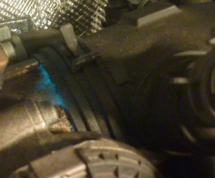
12 Leak Sample Three Ways to See the Leak White light highlights the smoke Laser light is reflected by the smoke vapor UV light sees the dye trace 8
13 LED Display Codes The LED display is capable of showing the following codes. re t.x.x CAL Fob End Pr9 Indicates Program Version or Revision; which will displayed next Program Version ( x.x indicates turbo program version number) Calibrate Key Fob End of function Program Lo bat Low Battery or Bad Battery Connection (shown in two consecutive displays) E01 E02 n0a PSI bar Utl Open Circuit (ground or power) There is pressure in the system to be tested; cannot calibrate. NOTE: this error code will be followed by the amount of pressure in the system to be tested. Relieve pressure in the system to be tested prior to continuing with the test. No Air (no air/gas connected to tester) Set to read PSI pressure (instead of bar) Set to read bar pressure (instead of PSI) Utilities 9

14 Programing Remote Control Fob Your remote control Fob has already been programmed at the factory. Follow this procedure if reprogramming becomes necessary, due to Fob replacement or after changing the Fob s battery. 1. Disconnect Tester from power. 2. Connect Tester to workshop air. 3. While pressing and holding the SET PRESSURE arrow UP button on the Tester: connect Tester to power. 4. When Utl (Utilities) is displayed; release arrow UP button. NOTE: Pr9 (Program) is displayed. 5. Momentarily press the red button on the Remote Fob and release. After two seconds press the red button again and release. NOTE: The display will now read End, indicating the remote is now programmed to the Tester. 6. Disconnect and reconnect Tester from power to resume normal operations. Setting Pressure Reading Default to PSI or BAR Your Tester has been preset at the factory to either default to PSI or BAR readings. Follow the steps below to change the default setting. 1. Disconnect Tester from power. 2. Connect Tester to workshop air. 3. While pressing and holding the SET PRESSURE arrows UP / DOWN buttons on the Tester: connect Tester to power. 4. When Utl (Utilities) is displayed; release UP / DOWN arrow buttons. 5. Push start button until you see PSI (or until you see bar, if system is preset to PSI). 6. Push arrow button DOWN once to read bar (or to read PSI, if system is preset to bar). 7. Push start. Disconnect and reconnect Tester from power to resume normal operations. 10

15 Warranty Technical Support LIMITED ONE (1) YEAR WARRANTY Smart Pressure Leak Detector Model WV711 Worldwide Vapor, Inc. Warrants To the Original Purchaser; under normal use, care and service, Tester shall be free from defects in material and workmanship for ONE YEAR from the date of original invoice. Seller's obligations under this warranty are limited solely to the repair or, at Seller's option, replacement of or refund of the original purchase price for, Equipment or parts which to Seller's satisfaction are determined to be defective and which are necessary, in Seller's judgment, to return the equipment to good operating condition. Repairs or replacements qualifying under this Warranty will be performed or made on regular business days during Seller's normal working hours within a reasonable time following Buyer's request. All requests for warranty service must be made during the stated warranty period. For Technical Support: (Opt. #2) Mon.-Fri. 8:00am to 3pm Pacific Time or TechSupport@vacutec.com Activate Your Warranty: To activate your warranty; send the information below to the address or fax number provided within 30 days of your purchase. Send information below to: TechSupport@vacutec.com or Fax: Purchaser s Name: Company Name: Address: Country: Telephone number: address: Web address: Smoke Machine Model: Serial Number: Date Purchased (keep your invoice for verification, if required): 11 Worldwide Vapor, Inc. Rev
16
INSTRUCTION MANUAL. Leakfinder. Model No. 625-WV609. BMW Smoke Tester. Diagnostic Smoke Vapor. with UltraTraceUV Dye Solution
 INSTRUCTION MANUAL Leakfinder Model No. 625-WV609 BMW Smoke Tester Diagnostic Smoke Vapor with UltraTraceUV Dye Solution Leak Detection System for the Professional Technician USA Canada Patents 6,392,227
Operator s Manual. Diagnostic Smoke Vapor Machine. with UltraTraceUV Dye Solution. Smoke Wizard Leak Detection System Model GLD-50
 Operator s Manual Diagnostic Smoke Vapor Machine with UltraTraceUV Dye Solution Smoke Wizard Leak Detection System Model GLD-50 USA Canada Patents 6,392,227 6,526,808 2,279,147 Int l Patents Pending TO
OPERATOR MANUAL. Vehicle Evaporative Emissions Leak Detection System Diagnostic Smoke Vapor Machine with Nitrogen Generator and UltraTraceUV Solution
 OPERATOR MANUAL Vehicle Evaporative Emissions Leak Detection System Diagnostic Smoke Vapor Machine with Nitrogen Generator and UltraTraceUV Solution Approved for Standard Petrol and Flex-Fuel Vehicle Testing
LeakTamer. with UltraTraceUV Dye Technology. Operator s Manual
 LeakTamer with UltraTraceUV Dye Technology Operator s Manual Table of Contents Table of Contents...1 Safety Precautions...2 Specifications...3 Tester Overview...4 Initial Setup...5 Test Setup...6 Basic
High Pressure Leak Diagnostics System Part No & NA USER MANUAL LEAK DETECTION SERVICE
 Cool Smoke HP High Pressure Leak Diagnostics System Part No. 500-0150 & 500-0150NA USER MANUAL LEAK DETECTION SERVICE 1324 Blundell Rd. Mississauga ON Tel. 905.615.8620 Fax. 905.615.9745 Introduction Congratulations!
OPERATOR S MANUAL. Diagnostic Smoke Vapor Machine. with UltraTraceUV Dye Solution
 OPERATOR S MANUAL Diagnostic Smoke Vapor Machine with UltraTraceUV Dye Solution Leak Detection System Model No. GLD40/JLR USA CA Patents 6,392,227 6,526,808 6,439,031 2,279,147 2,394,911 Int l and Other
Vehicle Evaporative Emissions Leak Detection System Diagnostic Smoke Vapor Machine with Nitrogen Generator and UltraTraceUV Dye Solution
 OPERATOR MANUAL Vehicle Evaporative Emissions Leak Detection System Diagnostic Smoke Vapor Machine with Nitrogen Generator and UltraTraceUV Dye Solution Part No. 625-522B-BMW Approved for Flex-Fuel Vehicle
OPERATOR MANUAL. Vehicle Evaporative Emissions Leak Detection System. Diagnostic Smoke Vapor Machine with Nitrogen Generator and UltraTraceUV Solution
 OPERATOR MANUAL Vehicle Evaporative Emissions Leak Detection System TM Diagnostic Smoke Vapor Machine with Nitrogen Generator and UltraTraceUV Solution Part No. 625-522B-BMW Approved for Flex-Fuel Vehicle
DUAL PURPOSE DIAGNOSTIC LEAK DETECTOR
 OPERATION MANUAL DUAL PURPOSE DIAGNOSTIC LEAK DETECTOR P/N 95-030 NIS -800-662-200 nissantechmate.com CONTENTS Specifications / Warranty... Functions...2-3 Accessories... 4 Set-Up... 5 Adaptor Installation...
1 of 7 12/18/2016 9:15 PM
 1 of 7 12/18/2016 9:15 PM P0456-EVAP SYSTEM SMALL LEAK Special Tools: For a complete wiring diagram, refer to the Wiring Information. 2 of 7 12/18/2016 9:15 PM Theory of Operation 3 of 7 12/18/2016 9:15
SPECIAL TOOLS BULLETIN
 SPECIAL TOOLS BULLETIN Title: "LEAK MASTER" EVAP SYSTEM "SMOKE" MACHINE Supersedes the April 15, 2004 edition Car Market: NORTH AMERICA : 1 of 5 YEAR MONTH DAY 2004 06 18 INTRODUCING THE LEAKMASTER J-45500-A!
EVAPORATIVE EMISSIONS TESTER KLI9210DLX OPERATION MANUAL
 EVAPORATIVE EMISSIONS TESTER KLI9210DLX OPERATION MANUAL Table of Contents GENERAL INFORMATION...1 UNPACKING & SETUP...2 Inlcuded Accessories...2 CHECK LIST...4 SELF-TEST INSTRUCTIONS...4 CALIBRATING
348002K/348012K Manifold Block Style Service Manual 12/2000
 348002K/348012K Manifold Block Style Service Manual 12/2000 Service Manual 348002K/348012K Manifold Block Style Recovery/Recycling/Recharging Unit For R-12 or R-134a Only TABLE OF CONTENTS: Theory of Operation
EVAPro Model No. 2000E
 EVAPro Model No. 2000E Vehicle Evaporative Emissions Leak Detection System TM Nitrogen Smoke Machine with UltraTraceUV Solution Operator s Manual USA Canada Patents 6,392,227 6,526,808 2,279,147 Int l
P0456-EVAP PURGE SYSTEM SMALL LEAK
 2014 Journey (2.4L L4) - JC P0456-EVAP PURGE SYSTEM SMALL LEAK Report a problem with this article Special Tools: Click to display a list of tools used in this procedure For a complete wiring diagram, refer
SMOKE PRO AIR COMPLETE DIAGNOSTIC LEAK DETECTOR
 SMOKE PRO AIR COMPLETE DIAGNOSTIC LEAK DETECTOR OPERATION MANUAL REDLINE MODEL NO: 95-0051 Manufactured in California, USA * CONGRATULATIONS Thank you for purchasing the Air Complete Diagnostic Leak Detector.
Automotive Air Conditioning Manifold Gauge Sets
 Automotive Air Conditioning Manifold Gauge Sets 1 Caution: These instructions are not for use with Hybrid Vehicles. For instructions for servicing Hybrid Vehicles use Hybrid Vehicle manufacturer s service
MODEL 905V OPERATING INSTRUCTIONS
 MODEL 905V OPERATING INSTRUCTIONS Quantek Instruments 183 Magill Drive Grafton, MA 01519 Tel: (508) 839-3940 Fax: (508) 819-3444 Email: sales@quantekinstruments.com GENERAL DESCRIPTION These instructions
Operators Quick Reference Manual. Smoke Pro
 Operators Quick Reference Manual Smoke Pro Page 2 of 12 Table of Contents Components and Accessories 3 Operation 6 Maintenance 10 Trouble Shooting 11 Output Pressure Gauge Start/Stop Button Flowmeter Flow
MODEL NUMBER: MEDIUM DUTY ONBOARD AIR SYSTEM
 MODEL NUMBER: 10003 MEDIUM DUTY ONBOARD AIR SYSTEM IMPORTANT: It is essential that you and any other operator of this product read and understand the contents of this manual before installing and using
P0456-EVAP PURGE SYSTEM SMALL LEAK
 0 - JK - JEEP WRANGLER - 38L V6 (SMPI) P0456-EVAP PURGE SYSTEM SMALL LEAK MODULE- POWERTRAIN ESIM SIGNAL EVAP PURGE CONTROL EVAP PURGE RETURN CONTROL 35 C3 0 C3 9 C3 K07 8 VT/WT 5 C300 K07 8 VT/WT ESIM
EBS PRODUCTS
 EBS PRODUCTS WWW.ebsproducts.com OPERATIONS MANUAL EPG-1 Power Steering - Gear Oil Fluid Service Equipment #1000-0060 1-1-16 TABLE OF CONTENTS I. SAFETY INFORMATION... 2 1.01 IMPORTANT SAFETY NOTICE...
IV. PROOF OF PURCHASE: A warranty claim must be accompanied by proof of the date of purchase.
 PD9100 / 9200 SERIES POWER CONVERTER OWNERS MANUAL PROGRESSIVE DYNAMICS, INC. POWER CONVERTER LIMITED WARRANTY I. LIMITED WARRANTY: Progressive Dynamics, Inc. warrants its power converter to be free from
OPERATION MANUAL ESX-2
 OPERATION MANUAL ESX-2 Fuel System Cleaner RTI Technologies, Inc 4075 East Market St. York, PA 17402 800-468-2321 www.rtitech.com Manual P/N 035-80873-00 (Rev A) Table of Contents Component Description...2
POOL PILOT SOFT TOUCH OPERATING, TROUBLESHOOTING AND TECHNICAL CHEAT SHEET
 POOL PILOT SOFT TOUCH OPERATING, TROUBLESHOOTING AND TECHNICAL CHEAT SHEET NORMAL OPERATING MODE OF SOFT TOUCH 1. Output Lights will pulsate to indicate Chlorine production. a. There are 7 lights to indicate
2003 Chevrolet S10 - Engine Performance & Emission Controls > Engine Controls - 4.3L > Diagn...
 Page 1 of 7 2003 Chevrolet S10 : Engine Performance & Emission Controls > Engine Controls -4.3L > Diagnostic Information And Procedures > DTC P0442 DTC P0442 DTC P0442 System Description This diagnostic
AEROMOTIVE Part # INSTALLATION INSTRUCTIONS
 AEROMOTIVE Part # 16303 INSTALLATION INSTRUCTIONS CAUTION: Installation of this product requires detailed knowledge of automotive systems and repair procedures. We recommend that this installation be carried
Fuel System Service & Diagnostic Equipment OPERATOR S MANUAL MCS 245
 Fuel System Service & Diagnostic Equipment OPERATOR S MANUAL MCS 245 Table of Contents Introduction...3 Overview...4 System Features and Functions...5 System Features and Functions... Hose and Battery
Installation & Operation Manual. IMPORTANT: This manual contains important information. READ AND KEEP FOR REFERENCE.
 Elecronic Preset Meter 2 Industrial Handheld Series Model EPM2-IND Standard Series IMPORTANT: This manual contains important information. READ AND KEEP FOR REFERENCE. IOM-139-02-EN (1-12) 53400-139 Rev.
Automotive Application ET01 Software Revision A 12/06
 Automotive Application ET01 Software Revision A 12/06 INTRODUCTION... 2 FUNCTIONAL DESCRIPTION... 3 INSTALLATION... 4 COMPONENT PLACEMENT... 4 PLUMBING AND WIRING... 5 MSBC OPERATION (ET-01)... 14 TIMED
HEAVY DUTY ONBOARD AIR SYSTEM PART NO
 IMPORTANT: It is essential that you and any other operator of this product read and understand the contents of this manual before installing and using this product. SAVE THIS MANUAL FOR FUTURE REFERENCE
HEAVY DUTY ONBOARD AIR SYSTEM
 HEAVY DUTY ONBOARD AIR SYSTEM PART NO. 10005 IMPORTANT: It is essential that you and any other operator of this product read and understand the contents of this manual before installing and using this
PUMP PLUS 2000 PLC MODEL #: PP AUTOMATIC DUAL OUTPUT BATTERY CHARGER INSTRUCTION MANUAL
 INSTRUCTION MANUAL PUMP PLUS 2000 PLC AUTOMATIC DUAL OUTPUT BATTERY CHARGER Supplied with Dual Bar Graph Display MODEL #: 091-237-12-PP INPUT: 120 Volt, 60 Hz, 3.5 Amps OUTPUT BATTERY 1 and 2: 15 or 18
EBS PRODUCTS
 ! EBS PRODUCTS WWW.ebsproducts.com OPERATIONS MANUAL EDS-1 Dip Stick Fluid Exchange Equipment #1000-0075 1-1-16 TABLE OF CONTENTS I. SAFETY INFORMATION... 2 1.01 IMPORTANT SAFETY NOTICE... 2 1.02 IMPORTANT
Battery Tester. GxT Incorporated, Cheboygan MI, U.S.A. All Rights Reserved E040-01G. 40 & 42HD Operator s Manual
 Battery Tester GxT Incorporated, Cheboygan MI, U.S.A. All Rights Reserved E040-01G 40 & 42HD Operator s Manual SPECIFICATIONS Measurement Range...Ferret 40... Ferret 42HD Battery Volts... 4.0 to 19.99...
EBS PRODUCTS
 ! EBS Coolant Flush EBS PRODUCTS www.ebsproducts.com OPERATIONS MANUAL EC-1 Coolant Flush #1000-0070 1-1-16! 1 EBS Products Westminster, CA 92683 Phone: 877-955-0515 Fax: 714-896-6711 E-mail: sales@ebsproducts.com
Flue Gas Analyzer IMR 1100F
 Flue Gas Analyzer IMR Environmental Equipment. Inc. 3634 Central Ave. St. Petersburg Florida 33711 Tel: 727-328-2818 Fax 727-328-2826 info@imrusa.com www.imrusa.com User Manual INTRODUCTION 3 SAFETY INSTRUCTIONS
EXT HEPA/CARBON FUME HOOD
 EXT HEPA/CARBON FUME HOOD POLYPROPYLENE Installation and Operations Manual EXT HEPA/CARBON FUME HOOD Installation and Operations Manual Revision: 28-Jun-18 Page 2 of 12 EXT HEPA/CARBON FUME HOOD Installation
EVAP system, servicing
 Page 1 of 65 20-130 EVAP system, servicing EVAP system components 1 - Cap nut 10 Nm 2 - Cover 3 - Stud For EVAP canister 15 Nm 4 - Sealing piece 5 - Bleed line To EVAP canister purge regulator valve -
TABLE OF CONTENTS. Page 1
 TABLE OF CONTENTS Safety Precautions and Warnings... 2 Introduction... 3 EZ-CHARGE Battery Conductance Testers... 3 EZ-CHARGE 100 Features... 3 EZ-CHARGE 200 Features... 4 Text Styles Used in this Manual...
MSD Boost Control Module PN 7763
 MSD Boost Control Module PN 7763 ONLINE PRODUCT REGISTRATION: Register your MSD product online. Registering your product will help if there is ever a warranty issue with your product and helps the MSD
MEDIUM DUTY ONBOARD AIR SYSTEM
 MEDIUM DUTY ONBOARD AIR SYSTEM PART NO. 10003 IMPORTANT: It is essential that you and any other operator of this product read and understand the contents of this manual before installing and using this
Kit User Guide. Wireless Digital Controller User Guide
 Kit 72000 Wireless Digital Controller User Guide UG-681 (03902) ECR 6629 User Guide For maximum effectiveness and safety, please read these instructions completely before proceeding with installation.
Seeker HL Source Transmitter. User s Guide
 Seeker HL Source Transmitter User s Guide Notice Every effort was made to ensure that the information in this manual was accurate at the time of printing. However, information is subject to change without
INSTALLATION GUIDE. Universal System for Zero Turn Mowers
 INSTALLATION GUIDE Universal System for Zero Turn Mowers Table of Contents General Information 1 Important Notice to Purchaser 2 Specifications 2 Intended Usage 2 Important Information 3 General Safety
MPT-250B SPECIFICATIONS AND OPERATING INSTRUCTIONS
 1. SAFETY The MPT-250B Wire Crimp Pull Tester is a force measurement device, and as such should be operated with due caution. Operators should wear safety glasses for eye protection because the crimp under
Technician Turbocharger Guide for the L Power Stroke Engine
 Technician Turbocharger Guide for the 2003.25 6.0L Power Stroke Engine Vanes VGT Actuator Piston Turbine Wheel Shaft Seal Compressor Wheel VGT Control Valve TURBOCHARGER DESCRIPTION AND BASIC OPERATION
IMPORTANT SAFETY INSTRUCTIONS
 Table of Contents Safety... 2 Specifications... 3 Functions... 4 Operation... 5 Maintenance... 7 Warranty... 7 SAFETY SPECIFICATIONS OPERATION MAINTENANCE WARNING SYMBOLS AND DEFINITIONS This is the safety
MSD Boost Control Module PN 77631
 MSD Boost Control Module PN 77631 ONLINE PRODUCT REGISTRATION: Register your MSD product online. Registering your product will help if there is ever a warranty issue with your product and helps the MSD
SECOND GENERATION Use this guide with unit serial number prefix beginning with BWF using Terra Power separator.
 Technical Information and Diagnostic Guide for SECOND GENERATION Use this guide with unit serial number prefix beginning with BWF using Terra Power separator. This guide will assist you in becoming more
Complete Home Water Protection
 Valve Complete Home Water Protection leaksmart is an innovative, wireless system that eliminates the threat of water damage by keeping you in constant control of your home s water supply. It not only detects
Operations Manual. Automated Fuel Maintenance System FUEL TECHNOLOGIES INTERNATIONAL
 Operations Manual Automated Fuel Maintenance System FTI-10A & 20A FUEL TECHNOLOGIES INTERNATIONAL Replacement Manuals Available on Website: www.fueltechnologiesinternational.com 07/15/2015 Rev E Fuel Technologies
WirelessAIR Advanced Integrated Remote
 Advanced Integrated Remote Gen 3 Kit 72000 Automatic Leveling Digital On-Board Compressor System MN-772 (021112) ECR 7233 INSTALLATION GUIDE For maximum effectiveness and safety, please read these instructions
ULTRA TEAM TABLE OF CONTENTS I. INTRODUCTION
 JACOBS "i.c.e. PAK" -. (import Car Energy PAK) ULTRA TEAM INSTALLATION INSTRUCTIONS LEGAL FOR INSTALLATION IN ALL 50 STATES PER CARB EO #D-19-32 NOTE TO INSTALLER:' Before starting installation, read this
AEROMOTIVE Part # Street Rod Fuel Pump System INSTALLATION INSTRUCTIONS
 AEROMOTIVE Part # 17201 Street Rod Fuel Pump System INSTALLATION INSTRUCTIONS CAUTION: Installation of this product requires detailed knowledge of automotive systems and repair procedures. We recommend
INSTALLATION AND USER MANUAL
 INSTALLATION AND USER MANUAL SDKIT-730 & SDKIT-734 100% Bolt-On 150 PSI Train Horn System for 2011-2015 F-250 & F-350 Super Duty P/N SDKIT-730 P/N SDKIT-734 Thank you for purchasing a Kleinn Air Horns
Owner s Manual & Safety Instructions
 Owner s Manual & Safety Instructions Save This Manual Keep this manual for the safety warnings and precautions, assembly, operating, inspection, maintenance and cleaning procedures. Write the product s
AUTO PUMP 12V MODEL #: V 12 VOLT DC AIR COMPRESSOR SYSTEM INSTRUCTION MANUAL. INPUT: Volts DC, 11 Amps OUTPUT: 100 PSI Max
 INSTRUCTION MANUAL AUTO PUMP 12V 12 VOLT DC AIR COMPRESSOR SYSTEM MODEL #: 091-9-12V INPUT: 10-15 Volts DC, 11 Amps OUTPUT: 100 PSI Max File: IM_091-9-12v_revC1.indd Rev: C1 Revised By: PSS/JRN Date: 08-16-2017
INSTALLATION AND OPERATION MANUAL ARM-4073 AUTOMATIC REPRESSURE MODULES
 INSTALLATION AND OPERATION MANUAL ARM-4073 AUTOMATIC REPRESSURE MODULES SYSTEM CONCEPT When not transferring fuel, the pressure in the underground closed piping system of a gasoline station may fall due
Installation and Maintenance Instructions. World Leader in Modular Torque Limiters. PTM-4 Load Monitor
 World Leader in Modular Torque Limiters Installation and Maintenance Instructions PTM-4 Load Monitor 1304 Twin Oaks Street Wichita Falls, Texas 76302 (940) 723-7800 Fax: (940) 723-7888 E-mail: sales@brunelcorp.com
OPERATION AND MAINTENANCE
 Table of Contents GENERAL INFORMATION INTRODUCTION... 1 Operating Specifications... 1 FEATURES... 1 SAFETY PRECAUTIONS... 2 SET-UP... 2 OPERATION AND MAINTENANCE TESTING AN IGNITION MODULE OR IGNITION
Troubleshooting Guide: Elevance Delivery Systems
 Troubleshooting Guide: Elevance Delivery Systems FOR USE BY MIDMARK TRAINED TECHNICIANS Contents Description / Links Troubleshooting Charts ICM Screens Assistant s Unit Instruments (Elevance & European)
230VAC Power Inverter 400W Owner s Manual
 400W 230VAC Power Inverter 400W Owner s Manual For safe and optimum performance, the Enerdrive epower Inverter must be used properly. Carefully read and follow all instructions and guidelines in this manual
AUTO CHARGE 12 HO MODEL #: MODEL #: MODEL #: AUTOMATIC SINGLE OUTPUT BATTERY CHARGER INSTRUCTION MANUAL
 INSTRUCTION MANUAL AUTO CHARGE 12 HO AUTOMATIC SINGLE OUTPUT BATTERY CHARGER MODEL #: 091-170-6 MODEL #: 091-170-12 MODEL #: 091-170-24 File: IM_091-170-xx_revd.indd Rev: D Revised By: MFG Date: 10-23-2013
MD10. Engine Controller. Installation and User Manual for the MD10 Engine Controller. Full Version
 MD10 Engine Controller Installation and User Manual for the MD10 Engine Controller. Full Version File: MartinMD10rev1.4.doc May 16, 2002 2 READ MANUAL BEFORE INSTALLING UNIT Receipt of shipment and warranty
DESIGN-AIRE SL-RSR-EC. Installation and Operations Manual
 DESIGN-AIRE SL-RSR-EC Installation and Operations Manual DESIGN-AIRE SL-RSR-EC Installation and Operations Manual Revision: 28-Jan-16 Page 2 of 15 DESIGN-AIRE SL-RSR-EC Installation and Operations Manual
QuickServe Online ( ) ISB6.7 CM2350 B101 Service Manual
 ISB6.7 CM2350 B101 Service Manual") Page 1 of 31 (/qs3/pubsys2/xml/en/manual/2883567/2883567-titlepage.html) Select Service Tools Recommended Cummins Service Tools 0.043 inch orificed diagnostic fuel line, Part Number 3164621 Diagnostic
Page 1 of 31 (/qs3/pubsys2/xml/en/manual/2883567/2883567-titlepage.html) Select Service Tools Recommended Cummins Service Tools 0.043 inch orificed diagnostic fuel line, Part Number 3164621 Diagnostic
DESIGN-AIRE SL-RSR-EC. Installation and Operations Manual
 DESIGN-AIRE SL-RSR-EC Installation and Operations Manual DESIGN-AIRE SL-RSR-EC Installation and Operations Manual Revision: 06-Feb-17 Page 2 of 15 DESIGN-AIRE SL-RSR-EC Installation and Operations Manual
CLEAN AIR WORKSTATION REVERSE FLOW. Installation and Operations Manual
 CLEAN AIR WORKSTATION REVERSE FLOW Installation and Operations Manual CLEAN AIR WORKSTATION REVERSE FLOW Installation and Operations Manual Revision: 16-Jan-17 Page 1 of 12 CLEAN AIR WORKSTATION REVERSE
EZ SDI TM Booster Pump Assembly
 EZ SDI TM Booster Pump Assembly Installation and Operating Manual 505-334-5865 ph 505-334-5867 fax www.rodisystems.com email: info@rodisystems.com 936 Highway 516 Aztec, NM 87410-2828 Manual Revisions
BBT-205. For 12-volt automotive starting batteries and starting/charging systems INSTRUCTION MANUAL
 For 12-volt automotive starting batteries and starting/charging systems INSTRUCTION MANUAL Blank page Contents Registering Your tester... 5 Caution... 6 Capabilities... 6 Display and Keypad... 6 Preparations
Manual Concentrate Management System
 Form 887 05/15 Manual Concentrate Management System with Automatic Flush INSTALLATION AND OPERATION MANUAL Unit Serial Number All quality FoamPro products are ruggedly designed, accurately machined, carefully
AEROMOTIVE Part # L Mustang Digital FMU INSTALLATION INSTRUCTIONS
 AEROMOTIVE Part # 17113 4.6L Mustang Digital FMU INSTALLATION INSTRUCTIONS CAUTION: Installation of this product requires detailed knowledge of automotive systems and repair procedures. We recommend that
ACF Operation Manual
 ACF-3000 Operation Manual MAHLE Aftermarket Inc., RTI Division 10 Innovation Drive York, Pennsylvania 17402 USA Phone: 717-840-0678 Toll Free: 800-468-2321 Web-site: www.rtitech.com Manual P/N: 035 81825
BC-9000 OPERATIONS MANUAL BATTERY CHARGER COFKO ELECTRONICS LLC COPYRIGHT 2014 P/N
 BC-9000 BATTERY CHARGER OPERATIONS MANUAL COFKO ELECTRONICS LLC COPYRIGHT 2014 P/N 4169-20 UNPACKING As you unpack your new BC-9000 battery charger, inspect the BC-9000 for signs of shipping damage. If
DA 35/70 EFI MIL SPEC
 DA 35/70 EFI MIL SPEC Electronic Fuel Injected Engines OWNER S MANUAL Table of Contents Section Page 1. General Safety 3 2. Un-Packing Your Engine 4 3. Getting Started 7 4. Maintenance 9 5. Absolute Ratings
USER GUIDE 1 USER GUIDE
 USER GUIDE 1 USER GUIDE 1 TABLE OF CONTENTS IN THE BOX...3 NAVIGATING THE MENUS...3 MENU LAYOUT...3 UPDATE YOUR PROGRAMMER...4 CONNECT WITH THE MOTORCYCLE...5 TUNE YOUR MOTORCYCLE...6 ADDITIONAL FEATURES...8
Reference Manual FM-200 Series
 Flush Manifold A/P FOR LIQUID LAUNDRY SUPPLY SYSTEMS Reference Manual FM-200 Series Copyright 2004 Nova Controls, Inc. P/N 20-07941-00 Rev. C i P/N 20-07941-00 Rev. C ii P/N 20-07941-00 Rev. C 1 Description
MDX-300 Series. For 12-volt automotive starting batteries and starting/charging systems INSTRUCTION MANUAL
 For 12-volt automotive starting batteries and starting/charging systems INSTRUCTION MANUAL Blank page Contents Caution... 4 Capabilities... 4 Display and Keypad... 4 Preparations Before the Test... 6 Connecting
QUALITY MISTING PUMPS
 TOTALLY ENCLOSED DIRECT DRIVE 60030KH, 60031KH, 60050KH, 60051KH 60100KH, 60101KH, 60150KH, 60151KH MISTING PUMP MANUAL INCLUDING: SPECIFICATION DATA, GENERAL SAFETY PRECAUTIONS, OPERATION, INSTALLATION,
High Performance Vacuum Pump Model 15120A/15121A Operating Manual...
 High Performance Vacuum Pump Model 15120A/15121A Operating Manual... Operating Manual Table of Contents Warnings...1 CoolTech high performance vacuum pumps...1 Pump components...2 Before using your vacuum
Atomic Absorption Spectroscopy
 Atomic Absorption Spectroscopy Atomic absorption spectroscopy (AAS) is a widely used technique for determining a large number of metals. In the most common implementation of AAS, a liquid sample containing
Reference Guide and Step-by-Step Installation Manual
 Reference Guide and Step-by-Step Installation Manual Some adjustable features listed on the following pages are NOT applicable for all applications. The year, make, and model of the vehicle will determine
AEROMOTIVE Part # INSTALLATION INSTRUCTIONS
 AEROMOTIVE Part # 16303 INSTALLATION INSTRUCTIONS CAUTION: Installation of this product requires detailed knowledge of automotive systems and repair procedures. We recommend that this installation be carried
Model 322 Automated Thermocouple Calibrator Operating Instructions. Product Description. Practical Instrument Electronics
 Model 322 Automated Thermocouple Calibrator Operating Instructions Product Description Easy to use With the PIECAL 322 you can check & calibrate all your thermocouple instruments and measure thermocouple
SSP-Series Portable Balances Operation Manual
 SSP-Series Portable Balances Operation Manual TABLE OF CONTENTS SAFETY PRECAUTIONS.. 1 GETTING STARED... 1 INSTALLATION & SET-UP 2 POWER CONNECTION & BATTERY OPERATION... 2 LEVELING... 3 CALIBRATION...
Model 6275RC 50% Duty Cycle Compressor
 Model 6275RC 50% Duty Cycle Compressor IMPORTANT: It is essential that you and any other operator of this product read and understand the contents of this manual before installing and using this product.
Plastic Collar Quick Connect Fitting Service
 2004 Chevrolet Silverado 1500 -Fuel Systems > Fuel Controls -4.8L, 5.3L, And 6.0L > Repair Ins... Page 1 of 10 2004 Chevrolet Silverado 1500 : Fuel Systems > Fuel Controls - 4.8L, 5.3L, And 6.0L > Repair
2009 Hickok Inc. All rights reserved.
 User Guide FPT2600-EX1 I/M Handheld Fuel Cap Test System No part of this manual may be reproduced or transmitted in any form or by any means, electronic or mechanical, without written permission from Hickok.
AUTO ISOLATOR I AN AUTOMATIC LOSSLESS BATTERY ISOLATOR FOR DUAL BATTERY SYSTEMS
 INSTRUCTION MANUAL AUTO ISOLATOR I AN AUTOMATIC LOSSLESS ISOLATOR FOR DUAL SYSTEMS MODEL #: 091-139-2-12 VOLTAGE: 12 VDC OUTPUT: 12 VOLTS, 3 AMPS PARALLELING : 200 AMPS File: IM-091-139-2-12 Rev: revc
EXT DUCTLESS FUME HOOD
 EXT DUCTLESS FUME HOOD POLYPROPYLENE Installation and Operations Manual EXT DUCTLESS FUME HOOD Installation and Operations Manual Revision: 1-Feb-16 Page 2 of 12 EXT DUCTLESS FUME HOOD Installation and
Full View Flow Indicator
 Full View Flow Indicator Threaded and Flanged Process Connection Installation / Operation / Maintenance Manual P.O. Box 1116 Twinsburg, OH 44087 Phone: 330/405-3040 Fax: 330/405-3070 E-mail: view@ljstar.com
PUMP PLUS 1000 PLC MODEL #: PP AUTOMATIC SINGLE OUTPUT BATTERY CHARGER INSTRUCTION MANUAL
 INSTRUCTION MANUAL PUMP PLUS 1000 PLC AUTOMATIC SINGLE OUTPUT BATTERY CHARGER Unit supplied with one of these displays MODEL #: 091-215-12-PP INPUT: 120 Volt, 60 Hz, 3.5 Amps OUTPUT BATTERY 1 and 2: 15
INSTALLATION GUIDE Table of Contents
 CT-3100 Automatic transmission remote engine starter systems. What s included..2 INSTALLATION GUIDE Table of Contents Door lock toggle mode..... 4 Notice...2 Installation points to remember. 2 Features..2
Product Guide: Series III Pump Control Board Set (RoHS)
") revised 04/08/10 Description: The Series III Pump Control Board Set provides motor drive and pump control for a wide assortment of pumps from Scientific Systems, Inc. The assembly consists of two circuit
revised 04/08/10 Description: The Series III Pump Control Board Set provides motor drive and pump control for a wide assortment of pumps from Scientific Systems, Inc. The assembly consists of two circuit
Crescent Flush Manifold FOR LIQUID LAUNDRY SUPPLY SYSTEMS
 Crescent Flush Manifold FOR LIQUID LAUNDRY SUPPLY SYSTEMS Reference Manual FM-300 Series Copyright 2005 Nova Controls, Inc. P/N 20-08195-00 Rev. B i ii 1 Description Overview The FM-300 series Flush Manifold
SERVICE INSTRUCTION PURGING OF LUBRICATION SYSTEM FOR ROTAX ENGINE TYPE 912 AND 914 (SERIES) SI SI Repeating symbols:
 SI SI Repeating symbols:") SERVICE INSTRUCTION PURGING OF LUBRICATION SYSTEM FOR ROTAX ENGINE TYPE 9 AND 914 (SERIES) Repeating symbols: Please, pay attention to the following symbols throughout this document emphasizing particular
SERVICE INSTRUCTION PURGING OF LUBRICATION SYSTEM FOR ROTAX ENGINE TYPE 9 AND 914 (SERIES) Repeating symbols: Please, pay attention to the following symbols throughout this document emphasizing particular
6 & 12 Volt Battery and Systems Tester with 100 Amp Load
 6 & 12 Volt Battery and Systems Tester with 100 Amp Load Form No. 841-731 -000 DESCRIPTION This Load Tester tests 6 or 12 volt automotive-size lead-acid batteries under load. It will also test 6 or 12
On Board Diagnostics II A PCED
 Page 1 of 8 HX18 DTC P0446 OR P1450: CHECK FOR VISUAL CAUSES OF EXCESSIVE FUEL TANK VACUUM Continuous Memory Diagnostic Trouble Code (DTC) P0446 or P1450 indicates that Self-Test has detected the Evaporative
REMOTE ENTRY PRO UNIQUE SERVICE TOOLS FOR THE AUTOMOTIVE PROFESSIONAL KEY FOB TESTER
 A/C DIAGNOSTICS A/C FLUSH A/C LEAK DETECTION A/C SERVICE TOOLS BATTERY WARNING DEVICE ELECTRICAL DIAGNOSTICS CLEANER KEY FOB LEAK DETECTION - MULTIPLE OXYGEN SENSOR PORTABLE 5-GAS ANALYZER RADIATOR SERVICE