FUELS AND LUBRICANTS LAB ( )
|
|
|
- Lucas Golden
- 6 years ago
- Views:
Transcription


1 Dundigal, Quthbullapur (M), Hyderabad DEPARTMENT OF MECHANICAL ENGINEERING LAB MANUAL FUELS AND LUBRICANTS LAB ( ) Document No: DATE OF ISSUE: COMPLIED BY: AUTHORISED BY MLRITM/ME/LAB/MANUAL/HT VERIFIED BY: MECH (HOD)
2 INDEX S. No CONTENT Page No. 1. Preface 2. Acknowledgement 3. General Instructions 4. Safety Precautions 5. Institute Vision And Mission 6. Department Vision Mission, Programme Educational Objectives And Specific Outcomes 7. Programme Outcomes 8. Course Structure, Objectives & Outcomes 9. Experiments Learning Outcomes 10. Experiments 1. Determination of Flash and Fire points of Liquid fuels/lubricants using: Abels Apparatus 2. Determination of Flash and Fire points of Liquid fuels/lubricants using: Pensky Martens Apparatus 3. Carbon residue test: Liquid fuels. 4. Determination of Viscosity of Liquid lubricants and Fuels using: Saybolt Viscometer 5. Determination of Viscosity of Liquid lubricants and Fuels using: Redwood Viscometer -I
3 6. Determination of Viscosity of Liquid lubricants and Fuels using: Redwood Viscometer - II 7. Determination of Viscosity of Liquid lubricants and Fuels using: Engler Viscometer 8. Determination of Calorific value: of Gaseous fuels using: Junkers Gas Calorimeter. 9. Determination of Calorific value: Solid/Liquid/ fuels using: Bomb Calorimeter. 10. Drop point and Penetration Apparatus for Grease. 11. ASTM Distillation Test Apparatus. 12. Cloud and Pour point Apparatus. 11. Sample Viva Questions 12. Acronyms And Abbreviations 13. Measurement Conversions
4 PREFACE This book entitled Fuels Lab Manual is intended for the use of Third semester (i.e., II-I) B.Tech (Mechanical) students of Marri Laxman Reddy Institute of Technology and Management, Dundigal, Hyderabad. The main objective of the Fuels Lab Manual is to furnish the conceptual understanding of the basic principles of chemical analysis involved in water and waste water analysis, before the students carry out laboratory experiments. This book lays foundation of certain basic concepts and skills that can be repeatedly employed by the students in their future endeavors. The main aim of this book is to develop the habit of scientific reasoning and providing answers to all the doubts that arise during the course of conducting experiments. The book was written as per the new syllabus prescribed by the JNTUH University in a simple language. Some of the additional experiments apart from the syllabus are also included in the book. These experiments will help the students to expertise in the analysis and reporting the water quality for drinking purpose. Hence we hope this book serve for better understanding by the student community with all details of experiments. By, A Nishanth Kumar, Assistant Professor, Department of Mechanical engineering
5 ACKNOWLEDGEMENT It was really a good experience, working at Fuels and Lubricants lab. First I would like to thank Sharon Bashyam Asst. Professor, Department of Mechanical Engineering, Marri Laxman Reddy Institute of technology & Management for giving the technical support in preparing the document. I express my sincere thanks to Mr. Sudhakar, Head of the Department of Mechanical Engineering, Marri Laxman Reddy Institute of technology & Management, for his concern towards me and gave me opportunity to prepare Fuels laboratory manual. I am deeply indebted and gratefully acknowledge the constant support and valuable patronage of Dr. R.Kotaih, Director, Marri Laxman Reddy Institute of technology & Management. I am unboundedly grateful to him for timely corrections and scholarly guidance. I express my hearty thanks to Dr. K.Venkateswara Reddy, Principal, Marri Laxman Reddy Institute of technology & Management, for giving me this wonderful opportunity for preparing the Fuels laboratory manual. At last, but not the least I would like to thanks the entire Mechanical Department faculties those who had inspired and helped me to achieve my goal. By, A Nishanth Kumar, Assistant Professor, Department of Mechanical engineering
6 GENERAL INSTRUCTIONS 1. Students are instructed to come to Fuels and Lubricants Laboratory on time. Late comers are not entertained in the lab. 2. Students should be punctual to the lab, if not; conducted experiments will not be repeated. 3. Students are expected to come prepared at home with the experiments which are going to performed. 4. Students are instructed to display their identity cards and apron before entering into the lab. 5. Students are instructed not to bring mobile phones to the lab. 6. The glass apparatus and other instruments used in Engineering Chemistry lab should be handled with care and responsibility. 7. Any damage to glassware and equipment during the lab session is student s responsibility and penalty or fine will be collected from the student. 8. Do not throw waste such as match sticks, filter papers etc. into the sink. They must be thrown into the waste bin. 9. Keep the water and gas taps closed except when these utilities are needed. 10. Replace the reagent bottles on the reagent shelves immediately after use. They must never be allowed to accumulate on the bench. 11. Students should update the records and lab observation books session wise. Before leaving the lab the student should get his lab observation book signed by the faculty. 12. Students should submit the lab records 2/3 days in advance to the concerned faculty members in the staffroom for their correction and return. 13. Students should not move around the lab during the lab session. 14. If any emergency arises, the student should take the permission from faculty member concerned in written format. 15. The faculty members may suspend any student from the lab session on disciplinary grounds. 16. Never cook up the result by recording false observations or by making manipulated calculations. 17. All the data should be prettified with the relevant units.
7 SAFETY PRECAUTIONS General Guidelines 1. Conduct yourself in a responsible manner at all times in the laboratory. 2. Be familiar with your lab experiment before you come to the lab. Follow all written and verbal instructions carefully. If you do not understand a direction or part of a procedure, ask the lecturer/instructor/technician before proceeding. 3. No student may work in the laboratory alone. The lab instructor/lecturer grant exceptions on a case by case basis. 4. When first entering a laboratory, do not touch any equipment, chemicals or other materials in the laboratory area until you are instructed to do so. 5. Do not eat, drink beverages or chew gum in the laboratory. Do not use laboratory glassware as containers for food or beverages. 6. Smoking is strictly not allowed in any indoor area. 7. No music allowed in the laboratory. Radio (including walkman) and other entertainment devices are not permitted. 8. No cellular phone is allowed in this laboratory. 9. Perform only those experiments authorized by the lecturer/instructor/technician. Never do anything in the laboratory that is not called for the laboratory procedures or by your lecture/instructor/technician. Carefully follow all instructions, both written and oral. Unauthorized experiments are prohibited. 10. Observe good housekeeping practices. Work areas should be kept clean and tidy at all times. 11. Horseplay, practical jokes, and pranks are dangerous and prohibited. 12. Bring only your laboratory manual, worksheets and report to the work area. Other materials (books, purses, backpacks, etc) should be stored in the cabinet. 13. Know the locations and operation procedures of all safety equipment including the first aid kit, eyewash station, safety shower, spill kit and fire extinguisher. 14. Be alert and proceed with caution at all times in the laboratory. Notify the lecturer/instructor immediately of any unsafe condition you observe. 15. Label and equipment instructions must be read carefully before use. Set up and use the prescribed apparatus as directed in the laboratory instructions provided by your lecturer/instructor.
8 16. Experiments must be personally monitored at all times. You will be assigned a laboratory station at which to work. Do not wander around the room, distract other students or interfere with laboratory experiments or others 17. Defeating safety devices or using equipment in a manner other than that which is intended will be grounds for dismissal from the lab. Clothing 1. Safety goggles and safety jacket must be worn whenever you work in lab. 2. Gloves should be worn whenever you use chemicals that cause skin irritations or need to handle hot equipment. 3. Mask should be worn every time you prepare the chemicals. 4. Safety shoes and hard hat should be worn at all times while in the laboratory. 5. Contact lenses should not be worn in the laboratory unless you have permission from your instructor. 6. Dress properly during a laboratory activity. 7. Long hair, dangling jewellery and loose or baggy clothing are a hazard in the laboratory. Long hair must be tied back and dangling jewellery and loose or baggy clothing must be secured. 8. Sandal, open-toed shoes, high heels or shoes with holes in the sols will not be worn in the lab. 9. Shorts and skirts are not permitted. 10. Instructor and laboratory assistant have a right dismiss to you from the laboratory if they found that you are not wearing proper safety clothing. Handling of Chemicals 1. Treat chemicals with respect and understand the chemicals you are using with Material Safety 2. Data Sheet (MSDS). The MSDS are available in the analytical room. 3. All chemicals in the laboratory are to be considered dangerous. Do not touch, taste or smell any chemical unless specifically instructed to do so. 4. Check the label on chemical bottles before removing any of the contents. Take only much chemical are you need. Smaller amounts often work better than larger amounts. 5. Label all containers and massing papers holding dry chemicals.
9 6. Never return unused chemicals to their original containers. 7. Never use mouth suction to fill a pipette. Use pipette bulb or pipette filler. 8. Acids must be handled with extreme care. Always add acids slowly to water, with slow stirring and swirling, being careful of the heat produced, particularly with sulfuric acid. 9. Handle flammable hazardous liquid over a pan to contain spills. Never dispense flammable liquids anywhere near a flame or source of heat. 10. Never take chemicals or other materials from the laboratory area 11. Take good care when transferring acids and other chemicals from one part of the laboratory to another. Hold them securely and in the method demonstrated by the instructor as you walk. 12. All wastes generated during the course of an experiment must be disposed of according to the lab instructor s directions. 13. Never mix chemicals in sink drains. 14. Sinks are to be used only for water and those solutions designated by the instructor. 15. Solid chemicals, metals, matches, filter paper, and all other insoluble materials are to be disposed of in the proper waste containers, not in the sink. 16. Checks the label of all waste containers twice before adding your chemicals waste to the container. 17. Cracked or broken glass should be placed in the special container for broken glass. 18. Keep hands away from your face, eyes, mouth and body while using chemicals. Wash your hands with soap and water after performing all experiments. Accidents and Injuries 1. Report any accidents (spill, breakage, etc) or injury (cut, burn, etc) to the lecturer/instructor/technician immediately, no matter how trivial it may appear. 2. If you or your lab partners are hurt, immediately tell to the instructor. 3. If a chemical should splash in your eye(s), immediately flush with running water from the eyewash station for at least 20 minutes. Notify the instructor immediately. 4. Spills should be cleaned up immediately.
10 Handling Glassware and Equipment 1. Inserting and removing glass tubing from rubber stopper can be dangerous. Always lubricate glassware (tubing, thistle tubes, thermometer, etc) before attempting to insert it in a stopper. Always protect your hands with tower or cotton gloves when inserting glass tubing into, or removing it from a rubber stopper. 2. When removing an electrical plug from its socket, grasp the plug, not the electrical cord. 3. Hands must be completely dry before touching an electrical switch, plug or outlet. 4. Examine glassware before each use. Never use chipped or cracked glassware. 5. Never use dirty glassware. 6. Do not immerse hot glassware in cold water; it may shatter. 7. Report damaged electrical equipment immediately. Look for things such as frayed cords, exposed wires and loose connections. Do not use damaged electrical equipment. 8. If you do not understand how to use a piece of equipment, ask the instructor for help. 9. Be careful when lifting heavy objects. Lift comfortably, avoid unnecessary bending, twisting, reaching out and excessive weights, lift gradually and keep in good physical shape. 10. Do not transfer glassware from one laboratory to another without permission from instructor. Heating Substances 1. Do not operate a hot plate by yourself. Take care that hair, clothing and hands are a safe distance from the hot plate at all times. Use of hot plate is only allowed in the presence of the lecturer/instructor/technician. 2. Heated glassware remains very hot for a long time. They should be set aside in a designated place to cool and picked up with caution. Use tongs or heat protective gloves if necessary. 3. Never look into a container that is being heated. 4. Do not place hot apparatus directly on the laboratory desk. Always use an insulated pad. Allow plenty of time for hot apparatus to cool before touching it. 5. If leaving a lab unattended, turn off all ignition sources and lock the doors.
11 Ended the Experiments At the end of the laboratory sessions, you should: 1. Shut off main gas outlet 2. Turn off the water inlet 3. Desk top, floor area and sink are clean 4. All equipment is cool, clean and arranged
12 INSTITUTION VISION AND MISSION VISION To establish as an ideal academic institutions in the service of the nation, the world and the humanity by graduating talented engineers to be ethically strong, globally competent by conducting high quality research, developing breakthrough technologies, and disseminating and preserving technical knowledge. OUR MISSION To fulfill the promised vision through the following strategic characteristics and aspirations: Contemporary and rigorous educational experiences that develop the engineers and managers. An atmosphere that facilitates personal commitment to the educational success of students in an environment that values diversity and community. Undergraduate programs that integrate global awareness, communication skills and team building. Education and training that prepares students for interdisciplinary engineering research and advanced problem solving abilities.
13 DEPARTMENT VISSION, MISSION, PROGRAMME EDUCATIONAL OBJECTIVES AND SPECIFIC OUTCOMES Vision Statement: The Mechanical Engineering Department strives for immense success in the field of education, research and development by nurturing the budding minds of young engineers inventing sets of new designs and new products which may be envisaged as the modalities to bring about a green future for humanity Mission Statement: 1. Equipping the students with manifold technical knowledge to make them efficient and independent thinkers and designers in national and international arena. 2. Encouraging students and faculties to be creative and to develop analytical abilities and efficiency in applying theories into practice, to develop and disseminate new knowledge. 3. Pursuing collaborative work in research and development organizations, industrial enterprises, Research and academic institutions of national and international, to introduce new knowledge and methods in engineering teaching and research in order to orient young minds towards industrial development. Program Educational Objectives (PEOs): PEO1: progress Graduates shall emerge as successful Mechanical engineer s as their career PEO2: Graduates apply engage in active research. fundamentals of engineering, in practical applications and PEO3: Mechanical Graduates shall have the ability to design products with interdisciplinary skills. PEO4: Graduates will serve the society with their professional skills Programme Outcomes Program outcomes are narrower statements that describe what students are expected to know and be able to do by the time of graduation. These relate to the skills, knowledge, and
14 behaviors. Engineering programs must demonstrate that their students attain the following out comes. 1. An ability to apply knowledge of mathematics, science and engineering 2. An ability to design and conduct experiments, as well as to analyze and interpret data 3. An ability to design a system, component, or process to meet desired needs within realistic constraints such as economic, environmental, social, political, ethical, health and safety, manufacturability, and sustainability. 4. An ability to function on multidisciplinary teams 5. An ability to identify, formulate, and solve engineering problems 6. An understanding of professional and ethical responsibility 7. An ability to communicate effectively, 8. The broad education necessary to understand the impact of engineering solutions in a global, economic, environmental, and societal context, 9. A recognition of the need for, and an ability to engage in life-long learning 10. A knowledge of contemporary issues 11. An ability to use the techniques, skills, and modern engineering tools necessary for engineering practice 12. An ability to explore the opportunities for rapid deployment of renewable energy in the functioning of Mechanical Engineering systems The above defined outcomes are envisaged in the broad context of the proposed program objectives. The learning objectives and outcomes are adequately complemented during the course work with adequate exposure to continuous changes in different engineering fields in order to enrich and strengthen the program of mechanical engineering. For instance, the graduates acquire adequate knowledge in using the state of art computational tools to solve complex engineering problems.
15 COURSE STRUCTURES, OBJECTIVES AND OUTCOMES Course Structure Fuels and Lubricants Laboratory will have a continuous evaluation during 3 rd semester for 25 session marks and 50 end semester examination marks. Out of the 25 marks for internal evaluation, day-to-day work in the laboratory shall be evaluated for 15 marks and internal practical examination shall be evaluated for 10 marks conducted by the laboratory teacher concerned. The end semester examination shall be conducted with an external examiner and internal examiner. The external examiner shall be appointed by the principal / Chief Controller of examinations Course Objective 1. To present a problem oriented in depth knowledge of automobile fuels and lubricants. 2. To address the underlying concepts and methods behind automobile fuels and lubricants. 3. Determination of Flash and Fire points of Liquid Fuels / Lubricants: Pensky marten s apparatus 4. Carbon Residue Test: Solid/ Liquid Fuels 5. Determination of Viscosity : Liquid Lubricants & Fuels : Saybolt viscometer, Redwood Viscometer, Engler s Viscometer 6. Determination of Calorific Value: Solid/Liquid/Gaseous Fuels: Bomb Calorimeter, Junker Calorimeter 7. Grease Penetration Test Course Outcome 1. The student can identify different areas of automobile fuels and lubricants 2. Can find the applications of all the areas in day to day life 3. Ability to characteristic and chase the fuels and Lubricants for the automobiles
16 EXPERIMENTS LEARNING OUTCOMES 1. The laboratory course critically deals with the characterization of fuels and lubricants 2. Apart from this it also concerns the flow properties of lubricants and their variation with temperature 3. The student will gain hands-on experience on the equipment that facilitates property evaluation of fuels and lubricants 4. This would provide the student to choose the fuels and lubricants for specific use in various mechanical and day to day applications. 5. Through the use of both theoretical techniques and experimentation, develop an appreciation for theoretical and practical limits to engine performance and fuel economy.
.")
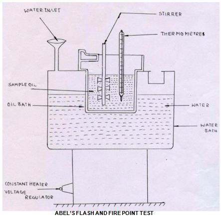
17 Experiment -1 ABEL S FLASH AND FIRE POINT TEST AIM To determine the flash and fire point of the given sample of oil using Abel s apparatus closed cup methods. APPARATUS Abel s apparatus, Thermo meter (0-110 o C). THEORY This method determines the closed cup flash and fire points of petroleum products and mixtures to ascertain whether they give off inflammable vapours below a certain temperature. FLASH POINT: It is the lowest temperatures of the oil, at which, application of test flame causes the vapour above the sample to ignite with a distinct flash inside the cup. FIRE POINT:
18 It is the lowest temperature of the oil, at which, application of test flame causes burning for a period of about five seconds. DESCRIPTION The apparatus consists of a brass cup and cover fitted with shutter mechanism, test flame arrangement, hand stirrer, thermometer socket. The brass cup is heated by water bath (with energy regulator), fitted with a funnel and overflow pipe. PROCEDURE 1. Clean the oil cup and fill the up to the mark with the sample oil. 2. Insert the thermometer into the oil cup through the provision to note down the oil temperature. 3. Using the Energy regulator, control the power supply given to the heater and rate of heating 4. The oil is heated slowly when temperature of oil rises; it is checked for the flash point for every one-degree rise in temperature. 5. After determining the flash point, the heating shall be further continued. The temperature at which time of flame application that causes burning for a period at least 5 seconds shall be recorded as the fire point. 6. Repeat the experiment 2 or 3 times with fresh sample of the same oil 7. Take the average value of flash and fire points. PRECAUTIONS: 1. Stir the oil bath continuously to maintain the uniform temperature of sample oil. 2. The bluish halo that some time surrounds the test flame should not be confused with true flash. OBSERVATIONS: Sample oil Flash Point, 0 C Fire Point, 0 C RESULT The flash point is observed at 0 C The fire point is observed at 0 C
19
 THEORY This method determines the closed cup and open cup flash and fire points of petroleum products and mixtures to ascertain whether")
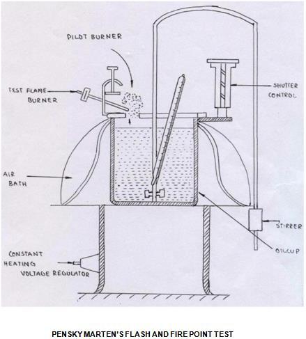
20 Experiment -2 PENSKY MARTEN S FLASH AND FIRE POINT TEST AIM To determine the flash and fire point of the given sample of oil using Pensky Marten s apparatus by both open and closed cup methods. APPARATUS Pensky Marten s apparatus Thermometer (0-110 o C) THEORY This method determines the closed cup and open cup flash and fire points of petroleum products and mixtures to ascertain whether they give off inflammable vapours below a certain temperature.
21 Flash Point: It is the lowest temperatures of the oil at which application of test flame causes the vapour above the sample to ignite with a distinct flash inside the cup. Fire point It is the lowest temperature of the oil, at which, application of test flame causes burning for a period of about five seconds. DESCRIPTION The apparatus consists of a brass cup and cover fitted with shutter mechanism without shutter mechanism (open cup), test flame arrangement, hand stirrer (closed cup), thermometer socket, etc., heated with energy regulator, a thermometer socket made of copper. PROCEDURE 1. Clean the oil cup thoroughly and fill the oil cup with the sample oil to be tested up to the mark. 2. Insert the thermometer into the oil cup through a provision, which measures the rise of oil temperature. 3. Using the Energy regulator, control the power supply given to the heater and rate of heating 4. The oil is heated slowly when temperature of oil rises, it is checked for the flash point for every one degree rise in temperature. 5. After determining the flash point, the heating shall be further continued. The temperature at which time of flame application which causes burning for a period at least 5 seconds shall be recorded as the fire point. 6. Repeat the experiment 2 or 3 times with fresh sample of the same oil 7. Take the average value of flash and fire points. PRECAUTIONS 1. Stir the oil bath continuously to maintain the uniform temperature of sample oil. 2. The bluish halo that some time surrounds the test flame should not be confused with true flash. OBSERVATIONS Sample oil Flash Point, 0 C Fire Point, 0 C RESULT The flash point is observed at 0 C The fire point is observed at 0 C
22
 apparatus Analytical balance with Weight box THEORY Most of the lubricant oils are containing high percentage of carbon in combined form and fuels containing less")
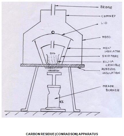
23 Experiment -3 CARBON RESIDUE (CONRADSON) TEST AIM To determine the carbon residue of the given sample of lubricating oil / Fuel. APPARATUS Carbon residue (Conradson) apparatus Analytical balance with Weight box THEORY Most of the lubricant oils are containing high percentage of carbon in combined form and fuels containing less percentage of carbon in combined form. On heating, they decompose depositing a certain amount of carbon. The deposition of such carbon in machine is
24 intolerable, particularly in internal combustion engines and air compressors. A good lubricant should deposit least amount of the carbon in use. PROCEDURE 1. The weighed porcelain or silica crucible with approximately 2 grams of sample is placed in the center of skid more crucible. 2. The skid more crucible is provided with lid, having a small tube type opening for the escape of volatile matter. 3. The combination is then placed in a wrought iron crucible covered with chimney shaped iron hood. 4. The wrought iron crucible is heated slowly till flame appears. Slow heating continues for 5 minutes more. 5. Finally, strong heating is done for about 15 minutes till vapors of all volatile matter are burnt completely. 6. Apparatus is then allowed to cool and weight of residue left is determined. 7. The result is expressed as percentage of the original weight of oil taken. OBSERVATIONS: 1. Weight of the crucible W1 = gms 2. Weight of the crucible with oil W2= gms 3. Weight of crucible with residue W3 = gms CALCULATION Percentage of carbon residue = [ (Weight of residue) / (original weight of sample)]x 100 = [(W3-W1)/(W2-W1)]x100 RESULT: The percentage of carbon present in given sample of lubricating oil is %
25

26 Experiment -4 SAYBOLT VISCOMETER AIM To determine the viscosity in Saybolt seconds of the given sample of oil and to plot the variation of Saybolt seconds, kinematic and dynamic viscosity with temperature. INSTRUMENTS Saybolt viscometer Stop watch
27 Thermometer ( C) Measuring flask (60 c.c) THEORY The viscosity of given oil is determined as the time of flow in Saybolt seconds. The viscosity of a fluid indicates the resistance offered to shear under laminar condition. Dynamic viscosity of a fluid is the tangential force on unit area of either of two parallel planes at unit distance apart when the space between the plates is filled with the fluid and one of the plate s moves relative to the other with unit velocity in its own plane. The unit of dynamic viscosity is dynesec/cm 2. Kinematic viscosity of a fluid is equal to the ratio of the dynamic viscosity and density of the fluid. The unit of kinematic viscosity is cm 2 /sec. DESCRIPTION Saybolt viscometer consists of a water bath and oil bath, both provided with two thermometers inside them. There is a ball valve, which is located at center of oil bath to flow of oil through the orifice. A heater with regulator is fixed for heating purpose. PROCEDURE 1. Clean the oil cup with a suitable solvent thoroughly and dry it using soft tissue paper. 2. Keep the cork in its position so as to keep the orifice closed. 3. The water is taken into the water bath and the oil whose viscosity is to be determined is taken into the oil cup up to the mark. 4. Before switch on the electric supply, at room temperature note down the time taken in Saybolt seconds for a collection of 60 c.c. of oil with a stop watch. 5. Heat the bath and continuously stir it taking care to see that heating of the bath is done in a careful and controlled manner. 6. When the desired temperature is reached, place the cleaned 60 c.c. flask below the orifice in position. 7. Remove the cork valve and simultaneously start a stopwatch. Note the time of collection of oil up to the 60 c.c. Mark. 8. During the collection of oil don t stir the bath. 9. Repeat the process at various temperatures. OBSERVATIONS Where A= cm 2 B= 1.8 cm 2 /sec 2 GRAPHS TO BE DRAWN 1. Saybolt seconds vs. temperature 2. Kinematic Viscosity vs. temperature
28 3. Dynamic Viscosity vs. temperature PRECAUTIONS 1. Stir the water continuously so that the temperature of the oil and water are equal. 2. Before collecting the oil at a temperature, check whether the oil is up to the level. 3. Always take the readings at a stable temperature. 4. Ensure proper setting of the cork to avoid leakage. RESULT Variation of Saybolt Seconds, Absolute viscosity and Kinematic viscosity with temperature, were observed and found to be decreasing with temperature

29 VIVA QUESTIONS 1. What is Viscosity? 2. What are different types of viscosity explain them and write the units? 3. What are factors effecting viscosity? 4. Mention some applications where viscosity is considered? 5. Relation between density and viscosity? 6. Mention different types of oils used in lubricating purposes?
30 7. How does SAE grade differ in lubricants oils used summer and winter? 8 How the power consumptions varies with viscosity of lubricant in rotation of shaft? 9. Selection of viscometers based on grading or viscosity of oil? 10. Which constructional feature of viscometer varies with the viscosity of oil?

31 Experiment -5 REDWOOD VISCOMETER I AIM To determine the viscosity in Redwood seconds of the given sample of oil and to plot the variation of Redwood seconds, kinematic and dynamic viscosity with temperature.
32 APPARATUS Redwood Viscometer- I Stop Watch Thermometer ( ) Measuring Flask (50 cc) THEORY The viscosity of given oil is determined as the time of flow in Redwood seconds. The viscosity of a fluid indicates the resistance offered to shear under laminar condition. Dynamic viscosity of a fluid is the tangential force on unit area of either of two parallel planes at unit distance apart when the space between the plates is filled with the fluid and one of the plate s moves relative to the other with unit velocity in its own plane. The u nit of dynamic viscosity is dyne-sec/cm 2. Kinematic viscosity of a fluid is equal to the ratio of the dynamic viscosity and density of the fluid. The unit of kinematic viscosity is cm2 /sec. DESCRIPTION Redwood viscometer-i consists of a water bath and oil bath, both provided with two thermometers inside them. There is a ball valve, which is located at center of oil bath to flow of oil through the orifice. A heater with regulator is fixed for heating purpose. PROCEDURE 1. Clean the oil cup with a suitable solvent thoroughly and dry it using soft tissue paper. 2. Keep the ball valve in its position so as to keep the orifice closed 3. The water is taken into the water bath and the oil whose viscosity is to be determined is taken into the oil cup up to the mark. 4. Note down the time taken in Redwood seconds for a collection of 50 cc. of oil with a stopwatch at the room temperature without supply of electric supply. 5. Heat the bath and continuously stir it taking care to see that heating of the bath is done in a careful and controlled manner. 6. When the desired temperature is reached, place the cleaned 50 c.c. Flask below the orifice in position. 7. Remove the ball valve and simultaneously start a stopwatch. Note the time of collection of oil up to the 50 c.c. Mark. 8. During the collection of oil don t stir the bath. Repeat the process at various temperatures. OBSERVATIONS
33 Where A= cm 2 B= 1.72 cm 2 /sec 2 GRAPHS TO BE DRAWN 1. Redwood seconds Vs. temperature 2. Kinematic Viscosity Vs. temperature 3. Absolute Viscosity Vs. Temperature PRECAUTIONS 1. Stir the water continuously so that the temperature of the oil and water are equal. 2. Before collecting the oil at a temperature, check whether the oil is up to the Indicator in the oil cup. 3. Always take the readings at a stable temperature 4. Ensure proper setting of the ball valve to avoid leakage RESULT Variation of Redwood seconds, absolute viscosity and Kinematic viscosity with temperature, were observed and found to be decreasing with temperature

34 VIVA QUESTIONS 1. What is Viscosity? 2. What are different types of viscosity explain them and write the units? 3. What are factors effecting viscosity? 4. Mention some applications where viscosity is considered? 5. Relation between density and viscosity? 6. Mention different types of oils used in lubricating purposes?
35

36 Experiment -6 REDWOOD VISCOMETER II AIM To determine the viscosity in redwood second of the given samples of oil and to plot the variation of Redwood seconds, kinematic and dynamic viscosity with temperature. INSTRUMENTS: Redwood Viscometer-II
37 Stop Watch Thermometer ( ) Measuring Flask (50 cc) THEORY The viscosity of given oil is determined as the time of flow in redwood seconds. The viscosity of a fluid indicates the resistance offered to shear under laminar condition. Dynamic viscosity of a fluid is the tangential force on unit area of either of two parallel planes at unit distance apart when the space between the plates is filled with the fluid and one of the plate s moves relative to the other with unit velocity in its own plane. The unit of dynamic viscosity is dyne- sec/cm 2. Kinematic viscosity of a fluid is equal to the ratio of the dynamic viscosity and density of the fluid. The unit of kinematic viscosity is cm 2 /sec. DESCRIPTION Redwood viscometer-ii consists of a water bath and oil bath, both provided with two thermometers inside them. There is a ball valve, which is located at center of oil bath to flow of oil through the orifice. A heater with regulator is fixed for heating purpose. PROCEDURE 1. Clean the oil cup with a suitable solvent thoroughly and dry it using soft tissue paper. 2. Keep the ball valve in its position so as to keep the orifice closed. 3. The water is taken into the water bath and the oil whose viscosity is to be determined is taken into the oil cup up to the mark. 4. Before switch on the electric supply, at room temperature note down the time taken in Redwood seconds for a collection of 50 c.c. of oil with a stopwatch. 5. Heat the bath and continuously stir it taking care to see that heating of the bath is done in a careful and controlled manner. 6. When the desired temperature is reached, place the cleaned 50 c.c. flask below the orifice in position. 7. Remove the ball valve and simultaneously start a stopwatch. 8. Note the time of collection of oil up to the 50 c.c. Mark. 9. During the collection of oil don t stir the bath 10. Repeat the process at various temperatures OBSERVATIONS
38 Where A= cm 2 B= 1.8 cm 2 /sec 2 GRAPHS TO BE DRAWN 1. Redwood seconds vs. temperature 2. Kinematic Viscosity vs. temperature 3. Absolute Viscosity vs. temperature PRECAUTIONS 1. Stir the water continuously so that the temperature of the oil and water are equal. 2. Before collecting the oil at a temperature, check whether the oil is up to the Indicator in the oil cup. 3. Always take the readings at a stable temperature 4. Ensure proper setting of the ball valve to avoid leakage RESULT Variation of Redwood seconds-ii, absolute viscosity and Kinematic viscosity with temperature, were observed and found to be decreasing with temperature

39 VIVA QUESTIONS 1. What is Viscosity? 2. What are different types of viscosity explain them and write the units? 3. What are factors effecting viscosity? 4. Mention some applications where viscosity is considered? 5. Relation between density and viscosity? 6. Mention different types of oils used in lubricating purposes?
40 7. How does SAE grade differ in lubricants oils used summer and winter? 8. How the power consumptions varies with viscosity of lubricant in rotation of shaft?
")
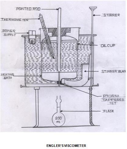
41 Experiment -7 ENGLER S VISCOMETER AIM To determine the viscosity in Engler s seconds of the given samples of oil and to plot the variation of Engler s seconds, kinematic and dynamic viscosity with temperature. APPARATUS Engler s viscometer Stopwatch Thermometer ( C) Measuring flask (200 c.c.)
42 THEORY The viscosity of given oil is determined as the time of flow in Engler s seconds. The viscosity of a fluid indicates the resistance offered to shear under laminar condition. Dynamic viscosity of a fluid is the tangential force on unit area of either of two parallel planes at unit distance apart when the space between the plates is filled with the fluid and one of the plate s moves relative to the other with unit velocity in its own plane. The unit of dynamic viscosity is dynesec/cm 2. Kinematic viscosity of a fluid is equal to the ratio of the dynamic viscosity and density of the fluid. The unit of kinematic viscosity is Cm 2 /sec. DESCRIPTION Engler s viscometer consists of a water bath and oil bath, both provided with two thermometers inside them. There is an ebonite valve stick, which is located at center of oil bath to flow of oil through the orifice. A heater with regulator is fixed for heating purpose. PROCEDURE 1. Clean the oil cup with a suitable solvent thoroughly and dry it using soft tissue paper. 2. Keep the ebonite valve stick in its position so as to keep the orifice closed 3. The water is taken into the water bath and the oil whose viscosity is to be determined is taken into the oil cup up to the mark. 4. Before switch on the electric supply, at room temperature note down the time taken in Engler s seconds for a collection of 200cc. of oil with a stopwatch. 5. Heat the bath and continuously stir it taking care to see that heating of the bath is done in a careful and controlled manner. 6. When the desired temperature is reached, place the cleaned 200 c.c. Flask below the orifice in position. 7. Remove the ebonite valve stick and simultaneously start a stopwatch. Note the time of collection of oil up to the 200 c.c. Mark. During the collection of oil don t stir the bath. 8. Repeat the process at various temperatures. OBSERVATIONS Where A= cm 2 B= 1.8 cm 2 /sec 2 GRAPHS TO BE DRAWN 1. Engler s seconds vs. temperature 2. Kinematic Viscosity vs. temperature 3. Absolute Viscosity vs. temperature Model graphs
43 PRECAUTIONS 1. Stir the water continuously so that the temperature of the oil and water are equal. 2. Before collecting the oil at a temperature, check whether the oil is up to the Indicator in the oil cup. 3. Always take the readings at a stable temperature 4. Ensure proper setting of the Ebonite stick to avoid leakage RESULTS Variation of Engler s seconds, Absolute viscosity and Kinematic viscosity with temperature, were observed and found to be decreasing with temperature
44
 Calorimeter a) Main calorimeter body b) Three thermometers ii) Gas flow")
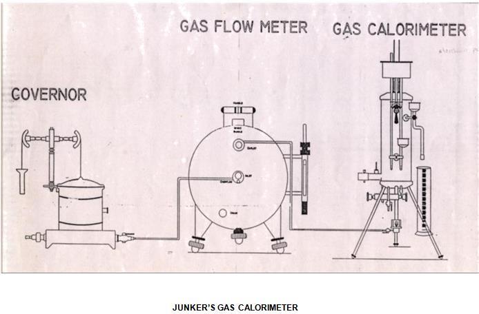
45 Experiment -8 JUNKER S GAS CALORIMETER AIM To find the calorific value of given gaseous fuel. APPARATUS i) Calorimeter a) Main calorimeter body b) Three thermometers ii) Gas flow meter
46 a) Main gas flow meter body b) Inlet / outlet nozzles c) Union net with washer for thermometers iii) Pressure governor a) Pressure governor body b) Balancing beam arrangement c) Counter balance tube d) Inlet and outlet union nuts with washers and iv) Jars 2000 ml & 50 ml PROCEDURE 1. Pour water into the governor till water starts overflowing through the overflow passage. 2. Replace and tighten the over flow nut. 3. Insert three thermometers provided with calorimeter into the rubber corks. 4. Insert rubber corks with thermometers into their places in calorimeter. 5. Insert burner into its support rod in the bottom of the calorimeter and turn the knurled knob so that the burner is fixed tightly. The burner must go into the center of the calorimeter body. 6. Connect the calorimeter, the flow meter and the pressure governor as shown in figure using rubber tubing provided. Do not connect gas supply line. Take care to see that the water regulator of calorimeter is in OFF position. 7. Turn water regulator knob on calorimeter to ON position. Allow water to flow through the calorimeter from overhead tank/ tap. Allow water to flow for 3 to 4 min into laboratory sink, through the calorimeter. 8. Ensure that outlet tap of governor is closed. Connect gas supply line to governor inlet. Remove burner from calorimeter then open governor outlet tap. Allow gas to pass through the burner. 9. Light up the burner by holding a lighted match stick near the mesh at the top. 10. Adjust the air regulator sleeve at the bottom of the burner to get a blue, non-luminous flame. Fix the lighted burner back into position. 11. Adjust water regulator on calorimeter to get a temperature difference of 12 0 C to 15 0 C between the inlet water & outlet water as indicated by the respective thermometers at the top of the calorimeter. 12. Allow 20 to 30 min for outlet water temperature to become steady. 13. Measure the water flow rate with the help of measuring jar. Simultaneously, note the flow meter reading. 14. Note down the inlet &outlet water temperatures. 15. Repeat the test with same volume of gas 3 or 4 times and take average temperatures of inlet and outlet water. CALCULATIONS The formula to be used to calculate the calorific value to the test gas is as follows
47 Where C.V = calorific value of gas in VG = volume of gas in liters consume during test period Vw = volume of water in liters passed during test period T2= outlet water temperature in 0 C T2= inlet water temperature in 0 C PRECAUTIONS 1. Test reading are to be taken only after steady condition are reached 2. Formation of steam should not be allowed. If there is formation of steam, then increase the flow of water or reduce the gas flow rate 3. Water flow rate should be steady. 4. The inner float of the pressure governor should not be removed since the outlet pressure may vary when refitted RESULT The calorific value gaseous fuel is Kcal/m 3
48

49 Experiment -9 BOMB CALORIMETER AIM To determine the water equivalent of the calorimeter using the given sample of solid or liquid fuel of known calorific value (or) To determine the calorific value of the given solid or liquid fuel if the water equivalent of the calorimeter known. APPARATUS Bomb, water jacket, stirrer, calorimeter vessel, combined lid, sensitive thermometer, analytical balance with weight box, oxygen cylinder with pressure gauge, fuse wire, cotton thread, firing unit, regulating valve and crucible hand pellet press
50 PRINCIPLE OF OPERATION A Bomb Calorimeter will measure the amount of heat generated when matter is burnt in a sealed chamber (Bomb) in an atmosphere of pure oxygen gas. A known amount of the sample of fuel is burnt in the sealed bomb, the air in the bomb being replaced by pure oxygen under pressure. The sample is ignited electrically. As the sample burns heat is produced and rises in the temperature. Since the amount of heat produced by burning the sample must be equal to the amount of heat absorbed by the calorimeter assembly, and rise in temperature enables the determination of heat of the combustion of the sample. If W = Water equivalent of the calorimeter assembly in calories per degree centigrade. T = Rise in temperature (registered by a sensitive thermometer) in degrees centigrade. H = Heat of combustion of material in calories per gram. M = Mass of sample burnt in grams. Then W x T x H x M If the water equivalent of the calorimeter is to be determined, a substance like Benzoic acid has a stable calorific value can be burnt in the bomb. Assuming the calorific value of Benzoic acid and water equivalent can be determined. CALORIFIC VALUE Gross or higher calorific value: The total amount of heat produced when one unit mass of fuel has been burnt completely and the products of combustion have been cooled to room temperature. Net or Lower Calorific Value: The net heat produced when unit mass of fuel is burnt completely and the products are permitted to escape. LCV = HCV Latent heat of water vapour formed DESCRIPTION Bomb The bomb consists of three parts i.e. bomb body, lid and the cap. Bomb Body and the lid are made of corrosion resistant stainless steel containing Chromium, Nickel and Molybdenum. The bomb body is cylindrical vessel having a capacity of 300 ml. The walls are strong enough to withstand the normal operating pressure (30atm) to extreme high pressures (300 atm.). During burning at high pressure the nitrogen and sulphur contents are oxidized to nitric acid and sulphuric acid respectively. The corrosion resistant nature of the bomb material protects it from corrosive vapors. The bomb has lid, which is provided with two terminals. The metallic rods pass through the terminals one of which are provided with a ring for placing the crucible with a small hook and the other with a groove. Each rod is also provided with a ring to press the fuse wire attached to it. The upper side of the lid also provided with a small hook rod lifting and with a Schrader valve for filling oxygen in the bomb
51 Water Jacket The water jacket is made of copper and is highly chromium plated on the inside and outside to minimize radiation losses. The jacket is filled with water. Stirrer Unit A stirrer is provided which is driven directly by an electric motor. The stirrer is immersed in the water. The water is continuously stirred during the experiment for uniform heat distribution. Combined Lid This is made of Borolite sheet and is provided with a hole for to keep the stirrer unit in fixed position and hole to insert the temperature sensor. It has also another hole to take out the connecting wires from the terminals on the bomb lid to firing unit. Hand Pellet Press It is used for pressing the powder into a pellet. Crucible It is made of stainless steel. The fuel to be burnt is weighed in this crucible. Ignition Wire It is recommended that platinum wire used but an alternative nichrome wire is also being offered. Firing Unit It consists of the firing key, provision to give power to the stirrer motor, a switch for operating the stirrer motor, two indicating lamps. When the circuit is completed the indicating lamp glows. After the firing key is closed on, the fuse wire burns, the indicating lamp stops glowing indicating the burning of the fuse wire. PROCEDURE 1. About 0.5 to 1grm of finely ground benzoic acid (Preferably compressed into a pellet) is accurately weighed and taken into crucible. 2. Place the bomb lid on the stand provided and stretch pieces of fuse wire across the electrodes (metal rods) provided in the lid tie about 5cm of sewing cotton round the wire. 3. Place the crucible in position and arrange the loose end of the cotton thread to contact the Benzoic acid pellet in the crucible.
52 4. About 10ml of distilled water are introduced into the bomb to absorb vapors of sulphuric acid and nitric acids formed during the combustion and lid of the bomb is screwed 5. Charge the bomb slowly with oxygen from the oxygen cylinder to a pressure of 25 atm. close the value and detach the bomb from the oxygen supply. 6. Fill the calorimeter vessel with sufficient water to submerge the cap of the bomb to a depth of at least 2mm leaving the terminals projecting lower the bomb carefully in the calorimeter vessel and after ascertaining that it is gas tight, connect the terminals to the ignition circuit. 7. Adjust the stirrer and place the temperature sensor and cover in position. 8. Start the stirring mechanism, which must be kept in continuous operation during the experiment after stirring for 5 minutes note the temperature reading of the calorimeter. 9. Close the circuit momentarily to fire the charge and continue the observations of the temperature at an interval of one minute till the rate of change of temperature becomes constant. 10. Afterwards stop the stirrer and remove the power supply to the firing unit. Remove the bomb from the calorimeter and relax the pressure by opening the value. 11. Verify that the combustion is complete and washout the contents of the bomb clean and dry. 12. Calculate the calorific value of the fuel or water equivalent of the calorimeter. OBSERVATIONS: Weight of the empty crucible W1 = gm Weight of the empty crucible + Benzoic acid pellet W2 = gm Weight of the benzoic acid pellet (W2 - W1 ) = gm Weight of water taken in the calorimeter W3 = gm Temperature of the water just before firing t1 = 0 C Temperature of the water just after firing t1 = 0 C CALCULATIONS Heat produced by burning of benzoic acid + Heat produced by burning of fuse wire and cotton wire etc = Heat absorbed by calorimeter. PRECAUTIONS 1. Sample should not exceed 1 gms. 2. Don t charge with more oxygen than is necessary. 3. Don t fire the bomb if gas bubbles are leaking from the bomb when it is submerged in water

53 RESULT Water equivalent of calorimeter We = Calorific value of sample Cv

54 Experiment -10 PENETRATION TEST AIM To determine the penetration of the given sample with the help of Penetrometer APPARATUS Penetrometer Needle Sample Cup Weights
55 DESCRIPTION Consistency or yield value is expressed in terms of penetration, which is defined as the distance in tenth of millimeter that a standard cone or needle penetrates vertically into the sample, under the standard conditions of load, temperature and time. Consistency of a sample depends on the structure and interaction of the gelling elements in it and to some extent on the viscosity of oil used. The consistency is determined by using Penetrometer. The apparatus consists of 1. Heavy base (of cast iron alloy): It is one which is provided with spirit level, leveling screws and a plain table, over which a box containing the sample under test is placed. 2. Vertical support is an iron rod fitted to the base. On this are slotted marks, around which a holder can be moved up and down. The holder has a screw, which can be tightened in any of the slots. 3. Circular dial: The holder carries a circular dial gauge, which is graduated in millimeters. 4. Moving dial rod: It is arranged behind the dial by a mechanical mechanism. The rod is provided with a clutch arrangement for disconnecting or connecting it to the circular dial. 5. Mirror: Vertical rod is provided with an adjustable mirror for removing parallax error while positioning the cone or needle in contact with sample surfaces PROCEDURE The apparatus is leveled, the cone or needle cleaned and the sample under-test, in a box, is placed below the cone or needle. The height of the cone or needle is so adjusted, that the tip of the cone or needle just touches the sample. Initial dial reading is noted. The cone is then released for exact 2 sec, by pressing a button is released and final dial reading is noted. The differences of the two dial readings given the penetration. This is repeated for three times and noted the total penetration in 6 sec. OBSERVATIONS INITIAL READING FINAL READING TIME ( sec ) OF DIAL OF DIAL d1 mm d 2 mm PENETRATION d 2 d1 mm

56 RESULT Penetration is found to be decreased with increasing temperature and time

57 Experiment -11 ASTM DISTILLATION TEST APPARATUS AIM 1. To determine the percentage of distilled amount against temperature of petroleum product sample. 2. To determine the initial and final boiling points of petroleum sample. 3. To determine the quantity of various fractions of petroleum sample.
58 APPARATUS The ISL Distillation Analyzer AD86 5G2 has been designed for the automatic distillation of hydrocarbons under prescribed conditions. A given volume of sample is distilled under appropriate conditions. Temperatures and volumes of condensate and times are systematically recorded. The distillation (or volatility) characteristics are calculated from the resulting data and are in turn used to determine the safety and performance of the sample. MATERIAL 100ml Kerosene INTRODUCTION ASTM Distillation is the most common method for obtaining distillation data (volume % distilled vs temperature) of gasoline, naphtha, kerosene and gas oil. In ASTM distillation, 100 ml of sample is distilled at uniform rate of 5ml per min, the distillate is condensed. The temperature of the vapour when the first drop of condensate dripped from the condenser is recorded as the initial boiling point (IBP). The vapour temperature is also recorded as each successive 10% is collected. When 95% has been distilled, the burner flame may need to be increased and the maximum temperature is recorded as the final boiling point (FBP). FBP is an important specification or way of describing gasoline, naphtha or middle distillates. DEFINITIONS Final Boiling Point (FBP): The maximum thermometer reading obtained during the test. Usually occurs after the evaporation of all liquid from the bottom of the flask. Initial Boiling Point (IBP): The temperature at the instant the first drop falls from the lower end of the condenser tube. Percent Residue: Percentage volume of residue left in the flask (measured in accordance with the standard in a 5ml flask). Percent Recovery : Volume measured after 2 minutes interval to successive observations agree (measured in accordance with standard method). Percent Total Recovery: Combination of percent recovery and percent residue in the flask. Deduct from 100 to obtain percentage loss. PROCEDURE 1. Preparation of the analyzer and apparatus 2. Swab the condenser tube using the pull through. 3. Place the ceramic (flask support) board with centred opening on the heating element support. 4. Put small quantity of pumice stone in the flask to stop lathering.
59 5. Pour the 100ml of prepared sample into the flask, taking care that none of it flows into the vapour tube. 6. Pass the vapour temperature probe through the D86 Flask Stopper, so that the top of the platinum coil of the probe is level with the bottom inner wall of the vapour tube. 7. Adjust the flask in vertical position, fitting the vapour tube (by means of its silicon stopper), so that it extends into the vapour tube between 25 and 50mm. 8. Turn the knob on the bottom of the heating block thus raising up the heating block so that the support boards fits snugly against the flask. 9. Place the provided rubber collar on the projecting lower end of the condenser tube in the receiver chamber. 10. Without drying the graduate, place it with its receiver deflector in position, under the lower end of the condenser tube. 11. The graduations of the graduate should be to the front and the tip of the receiver deflector should be in contact with the front inner wall of the graduate. Make sure the indicator lamp for the detection of the drops is not lit up. 12. Push down the rubber collar (on the end of the condenser tube) to cover the top of the graduate. 13. Close the door of the graduate compartment CALCULATION Volume Percent distilled Temperature o C FBP The Final Boiling point of the product = o C Volume Distilled = ml Residue left = ml Evaporated = ml RESULT Plot volume percent distilled and temperature Boiling range points is important property of petroleum products, when we send the products to the industries, they should have information about the properties of the petroleum products and one of them is the boiling range, and also it s important to take careful from the volatile liquid that are dangerous and toxic.
60 VIVA QUESTION 1. What information does the boiling range give on the composition, the properties and behavior of the fuel during storage and use? 2. How can distillation characteristics of hydrocarbon affect their safety and performance? 3. what is the major determinant of the tendency of a hydrocarbon 4. mixture to produce potentially explosive?
61

62 Experiment -12 CLOUD & POUR POINT TEST AIM To determine the cloud & pour point of a given fuel / lubricant / oil, using cloud &pour point apparatus APPARATUS Cloud & pour point apparatus Digital stem thermometer
Chem(Bio) Week 10 Bomb Calorimetry of Biodiesel
 Week 10 Bomb Calorimetry of Biodiesel") Lab Overview: Water/ check status plants (at some point) Biodiesel Workup (may not be necessary) Bomb Calorimetry of biodiesel (calorimeter calibration will be necessary) IR spectroscopy of biodiesel (possibly
Lab Overview: Water/ check status plants (at some point) Biodiesel Workup (may not be necessary) Bomb Calorimetry of biodiesel (calorimeter calibration will be necessary) IR spectroscopy of biodiesel (possibly
Biodiesel Production and Analysis
 Biodiesel Production and Analysis Introduction A key current focus in science and engineering is the development of technologies for generating and utilizing new sources of energy. Climate change, geopolitics,
Academic Course Description
 BEE305- ELECTRICAL MACHINES Academic Course Description BHARATH UNIVERSITY Faculty of Engineering and Technology Department of Electrical and Electronics Engineering BEE305- ELECTRICAL MACHINES Third Semester,
TESIGNG OF FUELS: VISCOSITY OF LIQUID FUELS
 Department of Mechanical Engineering Indian Institute of Technology New Delhi II Semester -- 2017 2018 MCL 241 Energy systems and Technologies TESIGNG OF FUELS: VISCOSITY OF LIQUID FUELS 1. Introduction
DEPARTMENT OF CHEMICAL ENGINEERING University of Engineering & Technology, Lahore. Energy Engineering Lab
 DEPARTMENT OF CHEMICAL ENGINEERING University of Engineering & Technology, Lahore Energy Engineering Lab Introduction Energy is often defined as the capacity to do work. Several different forms of energy,
Biodiesel Unit Lesson 2
 Terminal Objective 2: produce biodiesel Biodiesel Unit Lesson 2 Performance Objective 2: Given unused cooking oil, necessary equipment and chemicals, produce biodiesel that is free of soap, dry, and ready
U tube viscometer. Kinematic viscosity bath RASAYAN
 Viscosity The viscosity of a fluid is a measure of its resistance to gradual deformation by shear stress or tensile stress. For liquids, it corresponds to the informal notion of "thickness". For example,
TESTING OF FUELS : FLASH AND FIRE POINT
 Department of Mechanical Engineering Indian Institute of Technology New Delhi II Semester -- 2017 2018 MCL 241 Energy systems and Technologies TESTING OF FUELS : FLASH AND FIRE POINT 1. Introduction The
CHEMISTRY 135. Biodiesel Production and Analysis
 CHEMISTRY 135 General Chemistry II Biodiesel Production and Analysis The energy content of biodiesel can be roughly estimated with a simple laboratory apparatus. What features of biodiesel make it an attractive
Light condition and operation Windshield glass condition Wiper blade condition Paint condition and corrosion Fluid leaks Door and hood lock condition
 GENERAL CHECKS Engine Compartment The following should be checked regularly: Engine oil level and condition Transmission fluid level and condition Brake fluid level Clutch fluid level Engine coolant level
University Of California, Berkeley Department of Mechanical Engineering. ME 131 Vehicle Dynamics & Control (4 units)
") CATALOG DESCRIPTION University Of California, Berkeley Department of Mechanical Engineering ME 131 Vehicle Dynamics & Control (4 units) Undergraduate Elective Syllabus Physical understanding of automotive
CATALOG DESCRIPTION University Of California, Berkeley Department of Mechanical Engineering ME 131 Vehicle Dynamics & Control (4 units) Undergraduate Elective Syllabus Physical understanding of automotive
Today, we re going to talk about battery safety. We ll discuss all the key issues associated with using batteries safely, including battery hazards,
 Today, we re going to talk about battery safety. We ll discuss all the key issues associated with using batteries safely, including battery hazards, battery charging, and battery maintenance. Although
Biodiesel Production and Analysis
 Biodiesel Production and Analysis Introduction A key current focus in science and engineering is the development of technologies for generating and utilizing new sources of energy. Climate change, geopolitics,
CHAPTER-3 EXPERIMENTAL SETUP. The experimental set up is made with necessary. instrumentations to evaluate the performance, emission and
 95 CHAPTER-3 EXPERIMENTAL SETUP The experimental set up is made with necessary instrumentations to evaluate the performance, emission and combustion parameters of the compression ignition engine at different
PMA 5. Pensky-Martens Flash Point Tester. ::: Volatility... Flammability
 PMA 5 Pensky-Martens Flash Point Tester ::: Volatility... Flammability A Tradition of Competence 140 years of developing, producing and supporting excellent flammability instruments. 140 years of technology
Operation Manual BOTTLE TOP DISPENSER
 Operation Manual BOTTLE TOP DISPENSER TABLE OF CONTENTS Page No. Intended Use Of The Instrument 1 Safety Instructions 1 Functions and Limitations of Use 2 Operating Exclusions 3 Storage Conditions 3 Chemical
Document Library TS Data Sheet Universal Fuel System Cleaner. Data Sheet. Public
 Document Library TS Data Sheet 08955 Public Rev:1 Effective: 11/03/2000 Status: Active Universal Fuel System Cleaner Data Sheet 3M Part No.(s) 3M Part Descriptor(s) 08955 Professional Formula Universal
Powered Industrial Truck Safety Program
 Powered Industrial Truck Safety Program 0 TABLE OF CONTENTS Forklift Safety Program 1.0 Overview.. 2 2.0 Purpose....2 3.0 Procedures..2 4.0 Responsibilities. 4 5.0 Training Requirements......5 Appendix
ZINSSER-MINILAB A Complete Laboratory in a Case
 ZINSSER-MINILAB A Complete Laboratory in a Case The Zinsser-Minilab has been used in many European schools since the late 80s, but has also become a useful tool for the development and testing of new strategies
FLASH POINT TESTER. Instruction Manual. 0. Health and Safety Advice. 1. Introduction
 FLASH POINT TESTER Instruction Manual 0. Health and Safety Advice 1. Introduction 2. Devices and Accessories 3. Performing the Test 4. Replacement Orders 0. Health and Safety Advice Most important is not
Academic Course Description
 BME 503 FLUID POWER SYSTEMS Academic Course Description BHARATH UNIVERSITY Faculty of Engineering and Technology Department of Mechanical Engineering BME 503 FLUID POWER SYSTEMS Fifth Semester, 2015-16
Atomic Absorption Spectroscopy
 Atomic Absorption Spectroscopy Atomic absorption spectroscopy (AAS) is a widely used technique for determining a large number of metals. In the most common implementation of AAS, a liquid sample containing
Fractional Distillation Lab Simulating The Refining of Petroleum 12/12 Integrated Science 3 Redwood High School Name : Per:
 Simulating The Refining of Petroleum 12/12 Integrated Science 3 Redwood High School Name : Per: Introduction Petroleum, or crude oil, is a complex mixture of substances. It is believed that crude oil is
Sulphurous acid - environmental hazards due to the combustion of fossil fuels (Item No.: P )
") Teacher's/Lecturer's Sheet Sulphurous acid - environmental hazards due to the combustion of fossil fuels (Item No.: P7158000) Curricular Relevance Area of Expertise: Chemie Education Level: Klasse 7-10
Teacher's/Lecturer's Sheet Sulphurous acid - environmental hazards due to the combustion of fossil fuels (Item No.: P7158000) Curricular Relevance Area of Expertise: Chemie Education Level: Klasse 7-10
Engine oil. Introduction. Warning and indicator lights WARNING
 Engine oil Introduction In this section you ll find information about: Warning and indicator lights Engine oil specifications Engine oil capacities Checking the engine oil level and adding oil Engine oil
Fuel Related Definitions
 Fuel Related Definitions ASH The solid residue left when combustible material is thoroughly burned or is oxidized by chemical means. The ash content of a fuel is the non combustible residue found in the
Biodiesel. As fossil fuels become increasingly expensive to extract and produce, bio-diesel is
 Aaron Paternoster CHEM 380 10D Prof. Laurie Grove January 30, 2015 Biodiesel Introduction As fossil fuels become increasingly expensive to extract and produce, bio-diesel is proving to be an economically
Bomb Calorimetry and Viscometry: What Properties Make a Good Fuel?
 Bomb Calorimetry and Viscometry: What Properties Make a Good Fuel? Animal fats and vegetable oils consist of triglycerides. An example is shown below. Biodiesel is a renewable fuel created by transesterifying
Water pump Owner's Manual
 Water pump Owner's Manual Safety Precautions I. General Safeguards Please read this operation manual to have a thorough understanding of the content there before use the product. Failure to do so may lead
FULL AUTOMATIC ASPHALTENE ANALYZER APD-500A USER S GUIDE
 FULL AUTOMATIC ASPHALTENE ANALYZER APD-500A USER S GUIDE Please read this manual carefully to ensure correct use of this analyzer before you start to use it. COSMO TRADE & SERVICE CO., LTD. TABLE OF CONTENTS
Outsource Practices & Policies OPP
 Outsource Practices & Policies OPP 0900-300.2 SAFE OPERATION OF VEHICLES Introduction The purpose of this practice is to provide procedures for all employees of Outsource who drive on company business
Standard Test Method for Dropping Point of Lubricating Grease 1
 Designation: D 566 02 An American National Standard British Standard 2877 Designation: 132/96 Standard Test Method for Dropping Point of Lubricating Grease 1 This standard is issued under the fixed designation
Package Contents Part A (3) I-Beam (1) Base (2) Other parts
 I-Beam (1) Base (2) Other parts") Page 1 Installation Instructions for 81245 Adjustable Height Gantry Crane 1-Ton Capacity Table of Contents Important Safety Information pg. 2 Specific Operation Warnings pg. 2 Main Parts of Product pg.
Page 1 Installation Instructions for 81245 Adjustable Height Gantry Crane 1-Ton Capacity Table of Contents Important Safety Information pg. 2 Specific Operation Warnings pg. 2 Main Parts of Product pg.
Experiment 3: Ohm s Law; Electric Power. Don t take circuits apart until the instructor says you don't need to double-check anything.
 Experiment 3: Ohm s Law; Electric Power. How to use the digital meters: You have already used these for DC volts; turn the dial to "DCA" instead to get DC amps. If the meter has more than two connectors,
OWNER S MANUAL PRODUCT CODE: BOD1907
 OWNER S MANUAL PRODUCT CODE: BOD1907 90 LITRE OIL DRAINER EXTRACTOR Transparent Tank Vacuum Working Degree of Net Recovery Dimensions Capacity Pressure Vacuum Weight Chamber Capacity 90 Litre 10 Litre
Dress and Appearance
 Shop Safety Information Andover High School Explain how to work safely around these items. List Rules for using each item? Dress and Appearance Loose clothing shirts tucked Sleeves buttoned or rolled Me
ATD-6810 SPRAY GUN W/CUP INSTRUCTION MANUAL
 ATD-6810 SPRAY GUN W/CUP INSTRUCTION MANUAL Read this Instruction Manual carefully and understand it completely, basic precaution should be strictly followed to prevent the damage to the tool and injury
LIST OF PRACTICAL FOR IX-X GRADES
 LIST OF PRACTICAL FOR IX-X GRADES Standard experiments 1 To measure the area of cross section by measuring diameter of a solid cylinder with vernier callipers. 2 To measure the volume of a solid cylinder
Project Reference No.: 40S_B_MTECH_007
 PRODUCTION OF BIODIESEL FROM DAIRY WASH WATER SCUM THROUGH HETEROGENEOUS CATALYST AND PERFORMANCE EVALUATION OF TBC DIESEL ENGINE FOR DIFFERENT DIESEL AND METHANOL BLEND RATIOS Project Reference No.: 40S_B_MTECH_007
SECTION 7 1 DO IT YOURSELF MAINTENANCE MR2 U. Introduction
 SECTION 7 1 DO IT YOURSELF MAINTENANCE Introduction Engine compartment overview............................... 160 Trunk room overview........................................ 161 Fuse locations.............................................
Your web browser (Safari 7) is out of date. For more security, comfort and. the best experience on this site: Update your browser Ignore
 is out of date. For more security, comfort and. the best experience on this site: Update your browser Ignore") Your web browser (Safari 7) is out of date. For more security, comfort and Activitydevelop the best experience on this site: Update your browser Ignore Circuits with Friends What is a circuit, and what
Your web browser (Safari 7) is out of date. For more security, comfort and Activitydevelop the best experience on this site: Update your browser Ignore Circuits with Friends What is a circuit, and what
PROPANE TORCH WITH TURBO BURNER
 PROPANE TORCH WITH TURBO BURNER MODEL 91894 ASSEMBLY AND OPERATING INSTRUCTIONS 3491 Mission Oaks Blvd., Camarillo, CA 93011 Visit our Web site at http://www.harborfreight.com TO PREVENT SERIOUS INJURY,
SIP Direct Drive Oil-Lube Air Compressors - Operating & Maintenance Instructions
 SIP Direct Drive Oil-Lube Air Compressors - Operating & Maintenance Instructions Please read and fully understand the instructions in this manual before operation. Keep this manual safe for future reference.
Disc Brake System ( For Cross-Country)
") Technical Service Instructions General Safety Information Disc Brake System ( For Cross-Country) SI-8C60F t WARNING Please use extra caution to keep your fingers away from the rotating disc brake rotor
Technical Service Instructions General Safety Information Disc Brake System ( For Cross-Country) SI-8C60F t WARNING Please use extra caution to keep your fingers away from the rotating disc brake rotor
Voltmaster Centrifugal Trash Pumps
 Voltmaster Centrifugal Trash Pumps Model TSP2, TSP3 and TSP4 Owner s Manual February 2011 Table of Contents 1 Introduction............................ 1 1.1 Read before using..................... 1 1.2
ULVA+ TRAINING NOTES FOR WATER BASED SPRAYING KEY POINTS TO REMEMBER. Always wear the best protective clothing available
 KEY POINTS TO REMEMBER Always wear the best protective clothing available Always hold the sprayer downwind. Always start at the downwind edge of the field Only spray if there is a cross wind Never spray
MANUAL FLUID EXTRACTOR
 Please read and save these instructions. Read through this owner s manual carefully before using product. Protect yourself and others by observing all safety information, warnings, and cautions. Failure
HIGH PRESSURE FUEL PUMP 1
 2010 X250, 303-04 FUEL CHARGING AND CONTROLS - V8 5.0L PETROL HIGH PRESSURE FUEL PUMP 1 (G1185928) REMOVAL AND INSTALLATION 19.45.30 HIGH PRESSURE FUEL PUMP FRONT RENEW 5000 CC, AJ V8, NATURALLY ASPIRATED
MALCOM Table-Top Digital Viscometer Model PC-1TL Series
 MALCOM Table-Top Digital Viscometer Model PC-1TL Series INSTRUCTION MANUAL MALCOMTECH INTERNATIONAL 26200 INDUSTRIAL BLVD. HAYWARD, CA 94545 USA TEL. (510) 293-0580 FAX. (510) 293-0940 WEB. www.malcomtech.com
RESOLUTION MEPC.205(62) Adopted on 15 July GUIDELINES AND SPECIFICATIONS FOR ADD-ON EQUIPMENT FOR UPGRADING RESOLUTION
 Adopted on 15 July GUIDELINES AND SPECIFICATIONS FOR ADD-ON EQUIPMENT FOR UPGRADING RESOLUTION") MEPC.60(33)-COMPLIANT OIL FILTERING EQUIPMENT MEPC.60(33)-COMPLIANT OIL FILTERING EQUIPMENT MEPC 62/24/Add.1 Annex 24, page 1 ANNEX 24 RESOLUTION MEPC.205(62) 2011 GUIDELINES AND SPECIFICATIONS FOR ADD-ON
MEPC.60(33)-COMPLIANT OIL FILTERING EQUIPMENT MEPC.60(33)-COMPLIANT OIL FILTERING EQUIPMENT MEPC 62/24/Add.1 Annex 24, page 1 ANNEX 24 RESOLUTION MEPC.205(62) 2011 GUIDELINES AND SPECIFICATIONS FOR ADD-ON
White Paper.
 The Advantage of Real Atmospheric Distillation Complying with the ASTM D7345 Test Method in the Distillation Process Introduction / Background In the past, refiners enjoyed a constant supply of the same
Combustion Equipment. Combustion equipment for. Solid fuels Liquid fuels Gaseous fuels
 Combustion Equipment Combustion equipment for Solid fuels Liquid fuels Gaseous fuels Combustion equipment Each fuel type has relative advantages and disadvantages. The same is true with regard to firing
SAFE OPERATION 1. BEFORE OPERATION
 1 The best insurance against accidents is to abide by the safety regulations. Read and understand this manual carefully before operating the excavator. Every user, however experienced, should carefully
Methylene Blue Test Kit (115 Volt) (230 Volt) Instruction Manual. Updated 2/6/2017 Ver. 4.0
 (230 Volt) Instruction Manual. Updated 2/6/2017 Ver. 4.0") Methylene Blue Test Kit 168-00 (115 Volt) 168-00-1 (230 Volt) Instruction Manual Updated 2/6/2017 Ver. 4.0 OFI Testing Equipment, Inc. 11302 Steeplecrest Dr. Houston, Texas 77065 U.S.A. Tele: 832.320.7300
Methylene Blue Test Kit 168-00 (115 Volt) 168-00-1 (230 Volt) Instruction Manual Updated 2/6/2017 Ver. 4.0 OFI Testing Equipment, Inc. 11302 Steeplecrest Dr. Houston, Texas 77065 U.S.A. Tele: 832.320.7300
R&D on a Medium-speed, Four-cycle Diesel Engine Using Heavy fuel oil
 1999C.4.1.11 R&D on a Medium-speed, Four-cycle Diesel Engine Using Heavy fuel oil 1. R&D contents 1.1 Background and R&D objectives In order to meet increasing demand for light oil and intermediate fraction,
EBS PRODUCTS
 ! EBS Coolant Flush EBS PRODUCTS www.ebsproducts.com OPERATIONS MANUAL EC-1 Coolant Flush #1000-0070 1-1-16! 1 EBS Products Westminster, CA 92683 Phone: 877-955-0515 Fax: 714-896-6711 E-mail: sales@ebsproducts.com
JADE Bottle Top Dispenser
 Accrediting Certifying Bodies S C B A (E) ASCB(E) UK ISO 13485 JADE Bottle Top Dispenser Re-Circulation Valve Operation Manual TABLE OF CONTENTS Page No. Intended Use Of The Instrument 1 Safety Instruction
Battery. Student booklet
 Battery Student booklet Battery - INDEX - 2006-04-07-12:51 Battery Batteries are all over the place, in our cars, our PCs, laptops, portable MP3 players and cell phones. A battery is essentially a can
LABORATORY SAFETY SERIES: Electrical Safety
 ERI Safety Videos Videos for Safety Meetings 2952 LABORATORY SAFETY SERIES: Electrical Safety Leader s Guide Marcom Group Ltd. INTRODUCTION TO THE PROGRAM Structure and Organization Information in this
Powered Industrial Trucks
 INDIANA UNIVERSITY-PURDUE UNIVERSITY at INDIANAPOLIS IUPUI Department of Environmental Health and Safety 620 Union Drive, Room 043, Indianapolis, Indiana 46202 Powered Industrial Trucks Purpose and Background
SAFETY TRAINING LEAFLET 04 NITROUS OXIDE
 SAFETY TRAINING LEAFLET 04 NITROUS OXIDE Doc 23.04/18 EUROPEAN INDUSTRIAL GASES ASSOCIATION AISBL AVENUE DES ARTS 3-5 B 1210 BRUSSELS Tel: +32 2 217 70 98 Fax: +32 2 219 85 14 E-mail: info@eiga.eu Internet:
Redox Potentials and the Lead Acid Cell Minneapolis Community and Tech. College v I. Introduction. Part I
 Redox Potentials and the Lead Acid Cell Minneapolis Community and Tech. College v.11.10 I. Introduction Part I In these experiments you will first determine the reduction potentials of a series of five
AG-HA-2500N GASOLINE GENERATOR
 AG-HA-2500N GASOLINE GENERATOR OWNER S MANUAL BEFORE OPERATING THIS EQUIPMENT PLEASE READ THESE INSTRUCTIONS CAREFULLY (I)WARNING 1. Read the operator s instruction manual. 2. Attention! Exhaust gases
Automotive Curriculum
 Automotive Curriculum Degrees: Credential(s) AAS: Automotive Technology Tracks: Automotive Technician Track 69-72 Automotive Parts/Service Writer Track 61-64 Diploma: Automotive Technician 61-64 Automotive
D Instructions/Parts. Siphon Feed Detail Spray Gun D
 Instructions/Parts D-5-55 Siphon Feed Detail Spray Gun FOR PRODUCT INFORMATION CALL: 1-800-742-7731 309991D Important Safety Instructions Read all warnings and instructions in this manual. Save these instructions.
Heating Methods. Reflux and Distillation
 Heating Methods Reflux and Distillation Heating Methods Reflux Distillation Reflux You will use this next lab for the synthesis of aspirin not in this lab experiment Heating the reaction contents without
ENGINE & WORKING PRINCIPLES
 ENGINE & WORKING PRINCIPLES A heat engine is a machine, which converts heat energy into mechanical energy. The combustion of fuel such as coal, petrol, diesel generates heat. This heat is supplied to a
Auto Service Technician
 Auto Service Technician Organization Washburn Institute of Technology Program Number 47.0604 Instructional Level Certificate Target Population Grades 11 & 12 Post-secondary Description The Auto Service
ecognition of Prior Learning (RPL)
") ecognition of Prior Learning (RPL) EVIDENCE GUIDE FOR INSPECT AND LUBRICATE AN AUTOMOTIVE SYSTEM Evidence Guide inspect and lubricate an automotive system Page 1 of 15 National Certificate in Professional
ecognition of Prior Learning (RPL) EVIDENCE GUIDE FOR INSPECT AND LUBRICATE AN AUTOMOTIVE SYSTEM Evidence Guide inspect and lubricate an automotive system Page 1 of 15 National Certificate in Professional
PRESSURISED SANDBLASTER
 PRESSURISED SANDBLASTER MODEL NO: CPSB200 PART NO: 7640128 OPERATION & MAINTENANCE INSTRUCTIONS LS1211 INTRODUCTION Thank you for purchasing this Clarke Pressurised Sandblaster. Before you try to use this
Biodiesel: Making Renewable Fuel from Waste Oils
 Biodiesel: Making Renewable Fuel from Waste Oils Author/School: Matt Steiman, Wilson College, Chambersburg PA Introduction Biodiesel is a renewable fuel made from any biologically based oil, and can be
ABSOLUTE EQUIPMENT PTY LTD
 Manual Hydraulic Toe Jack Model DTJ Series ABSOLUTE EQUIPMENT PTY LTD 2/186 Granite Street, GEEBUNG QLD 4034 Australia sales@absoluteequipment.com.au Phone: +61 7 3865 4006 Fax: +61 7 3102 6288 This is
Significance of Each Test. 1. Color (Visual)
") Significance of Each Test 1. Color (Visual) Determine the color of lubricant product by assessing the appearance of transmitted light appearance and intensity, as compare with a standard. Color alone is
Significance of Each Test 1. Color (Visual) Determine the color of lubricant product by assessing the appearance of transmitted light appearance and intensity, as compare with a standard. Color alone is
Operating Manual for. Dispenser. Read this manual thoroughly before operating the Labmax Bottle Top Dispenser!
 Operating Manual for Dispenser Read this manual thoroughly before operating the Labmax Bottle Top Dispenser! General Safety Precautions When using the Labmax please observe the following safety precautions
ABSOLUTE EQUIPMENT PTY LTD
 Manual Hydraulic Toe Jack Model DTJ Series ABSOLUTE EQUIPMENT PTY LTD 2/186 Granite Street, GEEBUNG QLD 4034 Australia sales@absoluteequipment.com.au Phone: +61 7 3865 4006 Fax: +61 7 3102 6288 This is
INSTALLATION, OPERATION AND MAINTENANCE INSTRUCTIONS
 INSTALLATION, OPERATION AND MAINTENANCE INSTRUCTIONS Contents Section 1. General Observations... 2 2. Operation... 4 3. Control During Operation... 5 4. Trouble Shooting... 6 5. Maintenance... 7 Please
SECTION 8 1 DO IT YOURSELF MAINTENANCE. Introduction
 SECTION 8 1 DO IT YOURSELF MAINTENANCE Introduction Engine compartment overview............................... 396 Fuse locations............................................. 397 Do it yourself service
Starting up hydraulic systems
 General / Installation A hydraulic system that operates economically, safely, and trouble-free requires careful planning, as well as proper installation and start-up. Conscientious maintenance has a considerable
INSTALLATION AND OPERATING INSTRUCTIONS FOR FLOODED TUBULAR-HP AND TUBULAR-LM FAST CHARGE MOTIVE POWER BATTERIES
 PLEASE READ THESE INSTRUCTIONS BEFORE PLACING BATTERIES INTO SERVICE. THESE INSTRUCTIONS MUST BE SHIPPED WITH THE BATTERY AND MUST BE DELIVERED TO THE USER. INSTALLATION AND OPERATING INSTRUCTIONS FOR
GRAVITY FEED SPRAY GUN & CUP SPECIFICATIONS. Operating Instructions Warning Information Parts Breakdown. Fluid Orifice mm. Air Inlet:...
 Operating Instructions Warning Information Parts Breakdown SPECIFICATIONS Fluid Orifice... 1.4mm Air Inlet:...1/4 NPT Rec. Max. Inlet Pressure:...50 PSI CFM:... 3.1 at 50 PSI Nozzle Pressure... 10 PSI
CT0866 ORIGINAL INSTRUCTIONS SAVE
 600ML SPRAY GUN CT0866 ORIGINAL INSTRUCTIONS Cannon Tools Limited Address: 20 Station Road, Rowley Regis, West Midlands, B65 0JU.U.K. SAVE THESE INSTRUCTIONS AND PRECAUTIONS. READ ALL PRECAUTONS AND INSTRUCTIONS
Biodiesel Fundamentals for High School Chemistry Classes. Laboratory 7: Using Differences in Solubility to Remove Contaminants from Biodiesel
 Laboratory 7: Using Differences in Solubility to Remove Contaminants from Biodiesel Topics Covered Solubility Polarity Like dissolves like Partition Ratio Equipment Needed (per pair or group) One graduated
AUTO 140A: VEHICLE MAINTENANCE
 AUTO 140A: Vehicle Maintenance 1 AUTO 140A: VEHICLE MAINTENANCE Discipline AUTO - Automotive Technology Course Number 140A Course Title Vehicle Maintenance Catalog Course Description Intended for the incumbent
HOT AIR GUN MODEL No. CHG 1500B Part No
 HOT AIR GUN MODEL No. CHG 1500B Part No. 3400751 OPERATING & MAINTENANCE INSTRUCTIONS 0201 Thank you for selecting this CLARKE Hot Air Gun, which is designed for DIY and professional use alike. Before
AUT 163 AUTOMOTIVE FUNDAMENTALS SYLLABUS
 Instructor: Office: Jeremy Akin AUT 163 AUTOMOTIVE FUNDAMENTALS SYLLABUS Automotive office in Career -Tech Bldg. Phone: 989-275-5000 Ext. 356 Email: Jeremy.Akin@kirtland.edu Required Text: Modern Automotive
USE and MAINTENANCE INSTRUCTION MANUAL AZ3 HTE2 AZ3 HTE2 HVLP GRAVITY. SPRAY GUN Series. en it fr es pt de se
 USE and MAINTENANCE INSTRUCTION MANUAL AZ3 HTE2 AZ3 HTE2 HVLP GRAVITY SPRAY GUN Series en it fr es pt de se TECHNICAL DATA Technical AZ3 HTE2 AZ3 HTE2 HVLP 1.0 80 180 1.3 10-15HTE 140 200 240 1.5 2.0 160
AIR-COOLED DIESEL GENERATOR OWNERʼS MANUAL. This manual contains important safety information. TDG2500E TDGW7000E TDG7000SE TDG4500E
 AIR-COOLED DIESEL GENERATOR OWNERʼS MANUAL This manual contains important safety information. TDG2500E TDGW7000E TDG7000SE TDG4500E TDG8000-3 TDG7000SE-3 TDG7000E TDG8000E TDGW7000SE TDG7000E3 TDGW8000E
#9040 FUEL TANK SWEEPER
 #9040 FUEL TANK SWEEPER INSTRUCTION MANUAL FILTERS AND REMOVES FINE BIO-CONTAMINANTS, ALGAE, ETC. SWEEPING PROCESS REMOVES LARGE CONTAMINANTS FROM OIL TANKS SUCH AS RUST, WATER, CRUDE AND DIRT CIRCULATES
There s a lot of corn in the Midwest but can we use it to fly?
 There s a lot of corn in the Midwest but can we use it to fly? Grade Levels: 6-9 Lesson Length: Part II Making Biodiesel 1-2 class periods Problem Challenge: There is a lot of corn in the Midwest but can
2-1/4 Gallon Sprayer
 2-/4 Gallon Sprayer 94008 ASSEMBLY AND OPERATING INSTRUCTIONS 349 Mission Oaks Blvd., Camarillo, CA 930 Visit our Web site at http://www.harborfreight.com Copyright 2005 by Harbor Freight Tools. All rights
AC : USE OF POWER WHEELS CAR TO ILLUSTRATE ENGI- NEERING PRINCIPLES
 AC 2011-2029: USE OF POWER WHEELS CAR TO ILLUSTRATE ENGI- NEERING PRINCIPLES Dr. Howard Medoff, Pennsylvania State University, Ogontz Campus Associate Professor of Engineering, Penn State Abington Research
Refinery Supply Company, Inc.
 Refinery Supply Company, Inc. OPERATING INSTRUCTIONS Super Pressure Dead Weight Tester Catalog No. 35260 Serving the Oil & Gas Industry since 1923 9133-A East 46th Street Tulsa, Oklahoma 74145-4823 Voice
Cordless Rechargeable Saw Instructions for Use
 Technical data Voltage: DC 10.8V Weight: 1.25Kg Stroke rate: 0-2100/min Stroke: 15mm Cutting capacity: max diameter in wood 80mm / in soft metal 7mm Charging time: Between 5.0-5.5 Hours Battery: 1.3Ah
SAFETY RULES SPECIFICATIONS READ ALL INSTRUCTIONS BEFORE OPERATING SAVE THESE INSTRUCTIONS
 READ ALL INSTRUCTIONS BEFORE OPERATING SAVE THESE INSTRUCTIONS Thank you for purchasing 7" Polisher. Before attempting to operate your new Polisher please read these instructions thoroughly. You will need
Experimental Investigation of Hot Surface Ignition of Hydrocarbon-Air Mixtures
 Paper # 2D-09 7th US National Technical Meeting of the Combustion Institute Georgia Institute of Technology, Atlanta, GA Mar 20-23, 2011. Topic: Laminar Flames Experimental Investigation of Hot Surface
Cluster Knowledge and Skills for Business, Management and Administration Finance Marketing, Sales and Service Aligned with American Careers Business
 for Business, Management and Administration Finance Marketing, Sales and Service Aligned with American Careers Business About American Careers Correlations The following correlations are provided to demonstrate
INSTALLATION AND OPERATING INSTRUCTIONS FOR FLOODED TUBULAR-HP MOTIVE POWER BATTERIES
 PLEASE READ BEFORE PLACING BATTERIES IN SERVICE THESE INSTRUCTIONS TO BE SHIPPED WITH BATTERY AND TO BE DELIVERED TO USER INSTALLATION AND OPERATING INSTRUCTIONS FOR FLOODED TUBULAR-HP MOTIVE POWER BATTERIES
PERMEABILITY PLUGGING TESTER - P.P.T. OFI Part No
 OFI Testing Equipment Permeability Plugging Tester Instructions Part # 171-84 Page 1 of 9 Preparation PERMEABILITY PLUGGING TESTER - P.P.T. OFI Part No. 171-84 4000 psi (27,600 kpa) - 500 F (260 C) Capacity
User Guide. Lubricus Lubrication System LUB-D1/LUB-D2/LUB-D3/LUB-D4 (24 VDC)
") User Guide Lubricus Lubrication System LUB-D1/LUB-D2/LUB-D3/LUB-D4 (24 VDC) version 04/2013 Content General Information 3 Warning 3 Scope of Supply 3 Overview 3 General safety details 4 Intended use 4
User Guide Lubricus Lubrication System LUB-D1/LUB-D2/LUB-D3/LUB-D4 (24 VDC) version 04/2013 Content General Information 3 Warning 3 Scope of Supply 3 Overview 3 General safety details 4 Intended use 4
BG Diesel Fuel Products THE PROOF
 BG Diesel Fuel Products THE PROOF Field Test Metropolitan Atlanta Rapid Transit Authority BG DFC with Lubricity, Part No. 227, stopped accelerated corrosion that was occurring in underground fuel storage