INSTALLATION MANUAL FOR JABIRU 3300 AIRCRAFT ENGINE. DOCUMENT No. JEM3302-1
|
|
|
- Joanna Hubbard
- 6 years ago
- Views:
Transcription

1 INSTALLATION MANUAL FOR JABIRU 3300 AIRCRAFT ENGINE DOCUMENT No. JEM This Manual has been prepared as a guide to correctly install the Jabiru 3300 engine into an airframe. Should you have any questions or doubts about the contents of this manual, please contact Jabiru Aircraft Pty Ltd. Applicable to Jabiru 3300 Models from S/N 33A961 onwards (including 33A927, 33A928, 33A947, 33A948, 33A949, 33A950) HYDRAULIC LIFTER TYPE
2 1 TABLE OF CONTENTS 1 TABLE OF CONTENTS DESCRIPTION SPECIFICATIONS OPERATING LIMITATIONS DIMENSIONS DENOMINATION OF CYLINDERS ENGINE MOUNT CONTROLS INSTRUMENTS ELECTRICAL EQUIPMENT FUEL SUPPLY SYSTEM AIR INTAKE SYSTEM EXHAUST SYSTEM COOLING SYSTEMS...ERROR! BOOKMARK NOT DEFINED. 15 PROPELLER SELECTION AUXILIARY UNITS APPENDIX A WIRING DETAILS APPENDIX B SUPPLEMENTARY INFORMATION APPENDIX C JABIRU ENGINE INSTALLATION TIPS APPENDIX D NORMAL ENGINE FIGURES APPENDIX E TYPICAL INSTALLATION...37 REVISION Dated : 19/09/2007 Page: 2 of 51
3 1.1 Table of Figures Figure 1 Drawing W Engine Dimensions...8 Figure 2 Drawing Cylinder Denomination....9 Figure 3 Engine Mount Point Locations...10 Figure 4 Drawing Engine Mount Assembly...11 Figure 5 Drawing 4A264A0D. Electrical Wiring J160 Sheet Figure 6 Drawing 4A264A0D. Electrical Wiring J160 Sheet Figure 7 Regulator Plug Map...20 Figure 8 Propeller Installation (Jabiru Propeller)...29 Figure 9 Wiring Details...31 Figure 10. Intake Detail # Figure 11. Intake Detail # Figure 12. Engine Installation # Figure 13. Coil Cooling Detail # Figure 14. Coil Cooling Detail # Figure 15. Engine Accessory Pack Contents...39 Figure 16. Upper Engine Mount Detail...40 Figure 17 Lower Engine Mount Detail...41 Figure 18. Engine Mount Detail...42 Figure 19. Fuel Connections General...43 Figure 20. Fuel Connection Detail...43 Figure 21. Oil Collector Bottle...44 Figure 22. Hot Air Plumbing Incorrect...45 Figure 23 Hot Air Plumbing Correct...45 Figure 24. SCAT Hose Detail # Figure 25. Typical Hot Air Mixer Box...47 Figure 26. Control Connections to Carburettor...48 Figure 27. Balance Tube Detail # Figure 28. Carburettor Balance Tube Nipple...49 Figure 29. Oil Temperature Sensor...50 Figure 30. Oil Pressure Sensor...50 Figure 31. Tachometer Sensor Installation REVISION Dated : 19/09/2007 Page: 3 of 51
4 1.2 LIST OF EFFECTIVE PAGES The dates of issue for original & revised pages are: Page Revision Date Page Revision Date Page Revision Date /3/ /3/ /3/ /3/ /3/ /3/ /3/ /3/ /3/ /3/ /3/ /3/ /3/ /3/ /3/ /3/ /3/ /3/ /3/ /3/ /3/ /3/ /3/ /3/ /3/ /3/ /3/ /3/ /3/ /3/ /3/ /3/ /3/ /3/ /3/ /3/ /3/ /3/ /3/ /3/ /3/ /3/ /3/ /3/ /3/ /3/ /3/ /3/ /3/06 REVISION Dated : 19/09/2007 Page: 4 of 51
5 2 DESCRIPTION 2.1 Model All Jabiru 3300 Engine Models from S/No. N 33A961 onwards (including 33A927, 33A928, 33A947, 33A948, 33A949, 33A Details - 4 Stroke - 6 Cylinder Horizontally Opposed - 1 Central Camshaft - Push Rods - Over Head Valves (OHV) - Hydraulic Valve Lifters with Automatic Adjustment - Ram Air Cooled - Wet Sump Lubrication - Direct Propeller Drive - Dual Transistorised Magneto Ignition - Integrated AC Generator - Electric Starter - Mechanical Fuel Pump - Naturally Aspirated 1 Pressure Compensating Carburettor - 8 Bearing Crankshaft 2.3 Manufacturer Jabiru Aircraft Pty Ltd P.O. Box 5186 Bundaberg West Queensland Manuals Instruction & Maintenance Manual Parts Catalogue REVISION Dated : 19/09/2007 Page: 5 of 51
6 3 SPECIFICATIONS 3.1 General - Displacement : 3314 cc - Bore : 97.5 mm - Stroke : 74 mm - Compression Ratio : 8:1 - Direction of Rotation of Prop Shaft : Clockwise Pilot s view Tractor Applications - Ramp Weight : 81 kg (178 lbs) Complete including Exhaust, Carburettor, Starter Motor, Alternator & Ignition System. - Ignition Timing : 25 o BTDC - Firing Order : DC Output : 20 Amps - Fuel 75% Power : 24 l/hr (6 US gal/hr) - Fuel : AVGAS 100LL and AVGAS 100/130 Leaded and Unleaded Motor Gasoline above 95 (AKI 90) Octane RON may be used if AVGAS is not available. - Oil : Aero Oil W Multigrade 15W-50, or equivalent Lubricant complying with MIL-L-22851C, or Lycoming Spec. 301F, or Teledyne Continental Spec MHF-24B - Oil Capacity : 3.5 L (3.69 US Quarts) - Spark Plugs : NGK D9EA Automotive 3.2 Performance Static sea level ratings under the following conditions:- International Standard Atmospheric conditions at sea level. Aircraft service equipment drives unloaded. (Vacuum Pump not fitted) Full rich fuel/air mixture. Maximum cylinder head temperature. Standard Jabiru air filter and cold air. Standard exhaust muffler Engine Ratings Takeoff/Max Continuous 120 hp / 3300 RPM Fuel Consumption 35 Takeoff/Max Continuous Rating Oil Consumption 0.1 L/hr (max) REVISION Dated : 19/09/2007 Page: 6 of 51
7 4 OPERATING LIMITATIONS 4.1 RPM - Continuous: 3300 RPM / Full Throttle - Recommended Cruise: 2750 RPM 3100 RPM 4.2 Engine Cooling Maximum Cylinder Head Temperatures measured under exhaust spark plug. Maximum Peak Temperature 200ºC (392 F) Continuous Operation 180ºC (356 F) 4.3 Fuel Specifications Avgas 100LL & Avgas 100/130 Leaded and Unleaded Automotive Gasoline above 95 Octane RON (AKI 90 & above) 4.4 Pressure to Carburettor (Gauge Pressure) Maximum 20 kpa (3 psi) Minimum 5 kpa (0.75 psi) WARNING When using auto fuels, ensure all components of the fuel delivery system are cooled to prevent fuel vaporization. 4.5 Oil Specifications - Aero Oil W Multigrade 15W-50, or equivalent Lubricant complying with MIL-L-22851C, or - Lycoming Spec. 301F, or - Teledyne - Continental Spec MHF-24B Oil Temperature Minimum for Take-off Power 50 C (122 F) Maximum 118 C (244 F) Continuous 80 C 100 C (176 F F) Pressure Normal Operations: Min 220 kpa (32 psi) Max 525 kpa (76 psi) Idle: Min 80 kpa (12 psi) Starting & Warm Up: Max 525 kpa (76 psi) REVISION Dated : 19/09/2007 Page: 7 of 51
8 5 DIMENSIONS Figure 1 Drawing W Engine Dimensions REVISION Dated : 19/09/2007 Page: 8 of 51
9 6 DENOMINATION OF CYLINDERS Cylinder Firing Order: Figure 2 Drawing Cylinder Denomination. REVISION Dated : 19/09/2007 Page: 9 of 51
10 7 ENGINE MOUNT The design of the engine mount must not only take into account the structural loadings but must make allowances for accessibility of components and the removal of equipment located at the rear of the engine. The engine has four engine mounting points located at the rear of the engine (refer to Figure 3) from which the engine is to be mounted. An optional bed mount may be fitted. Figure 3 Engine Mount Point Locations The correct installation is shown below in Figure 4. REVISION Dated : 19/09/2007 Page: 10 of 51
11 Figure 4 Drawing Engine Mount Assembly Corrections of the engine alignment may be made using spacers under the rubber cushions. The maximum spacer thickness on any one mount is 3mm. REVISION Dated : 19/09/2007 Page: 11 of 51
12 8 CONTROLS This section comprises of the mechanical controls and electrical switches. 8.1 Throttle and Choke Provisions for the connection of the throttle and choke are made on the carburettor. Note: Since a pressure compensating carburettor is used there is no mixture control Master Switch, Ignition Switches and Starter Button The switches are connected as shown by the circuit diagram, shown in Figure 5 and Figure 6. REVISION Dated : 19/09/2007 Page: 12 of 51
13 9 INSTRUMENTS 9.1 Electronic Tachometer The tachometer uses an induction type sender which reads off 2 metal tags attached to the forward (inner) face of the flywheel Tachometer Wiring 3 Tachometer Negative (3) to Earth 4 Tachometer Positive (4) to Instrument 8 Tachometer to Red Wire tachometer pick-up 7 Tachometer to Black Wire tachometer pick-up 9.2 Oil Temperature Gauge The Oil Temperature Gauge uses an electric probe mounted in the base of the sump. Jabiru Part No. PI10752N is recommended Oil Temperature Wiring Black Oil Temperature Gauge Negative to Earth Red Oil Temperature Gauge Positive to Instrument White Oil Temperature Gauge Sensor (S) to Oil Temperature Sensor (Lower Left Eng Sump) 9.3 Oil Pressure Gauge An electric oil pressure sender is fitted to the engine for an Oil Pressure Gauge. Jabiru Part No. PI10762N is the recommended gauge Oil Pressure Wiring Black Oil Pressure Gauge Negative to Earth Red Oil Pressure Gauge Positive to Instrument White Oil Pressure Gauge Sensor (S) to Oil Pressure Sensor (Fwd Top Eng) 9.4 Cylinder Head Temperature Gauge The Cylinder Head Temperature Gauge uses a thermocouple. An audit must be done to establish the hottest cylinder and the thermocouple probe should be fitted under the exhaust spark plug on that cylinder. Jabiru Part No. PI10732N is the recommended gauge Cylinder Head Temperature Wiring & Sender Loom and sensor is supplied with the instrument. These must be installed as per directions. If cable is too long it must be looped as many times as necessary and strapped behind the instrument panel. Temperature of cold junction for best results should be around 50ºC. Ensure cold junction is as far from the thermocouple probe as possible. REVISION Dated : 19/09/2007 Page: 13 of 51
14 DO NOT CUT TO LENGTH Ensure that wire is not chaffing on the fibreglass air duct or cooing fins. No power connection is required. 9.5 Exhaust Gas Temperature Gauge An optional Exhaust Gas Temperature Gauge can be fitted. The probe should be positioned 100mm from the port flange on the exhaust pipe of a convenient cylinder. Jabiru Part No. PI0325N is the recommended gauge. Note that due to the special needle fitted to the engine, EGTs will be higher at cruise power than at full power. Refer to section for details. REVISION Dated : 19/09/2007 Page: 14 of 51
15 Figure 5 Drawing 4A264A0D. Electrical Wiring J160 Sheet 1 REVISION Dated : 19/09/2007 Page: 15 of 51
16 Figure 6 Drawing 4A264A0D. Electrical Wiring J160 Sheet 2. REVISION Dated : 19/09/2007 Page: 16 of 51
17 NOTE: The wiring diagram shown above is for the Jabiru J160-C. It shows the correct wiring systems to use on all Jabiru engines. REVISION Dated : 19/09/2007 Page: 17 of 51
18 10 ELECTRICAL EQUIPMENT 10.1 Alternator The alternator fitted to the Jabiru 3300 engines is single phase, permanently excited AC type, controlled by a regulator. The rotor is mounted on the flywheel with the stator mounted on the alternator mount plate at the back of the engine. The alternator mount plate is also the mount for the ignition coils and the vacuum pump Alternator Specifications (single phase): Power (Max): 200W Continuous NOTE: The electrical system is Negative Earth Regulator The regulator has been selected to match the voltage and current of the integral alternator fitted. Only Jabiru Part No. PI10652N should be used. (The regulator output is 14 Volts ±0.8 Volt) Recommended wiring of regulator is positive and negative directly to battery. A suitable fuse in series is recommended Ignition The ignition unit has dual breakerless transistorised ignition with the magnets mounted on the flywheel and the coils mounted on the alternator mount plate. The current from the coils flows to the distributor from where it is distributed to the spark plugs. (See also Regulator Wiring at Figure 5, Figure 6 and Figure 7.) The ignition is turned off by grounding the coils via the ignition switches. The ignition is timed to 25 o BTDC The temperature limit for the ignition coils is 70 C. This should be checked by the installer. It is recommended to fit a small pipe around ½ inch (12mm dia) from the top rear of the air duct and routed down to the coil to assist in cooling. Ignition coils should be mounted on insulating washers. Coils are mounted with outlet lead following direction of prop rotation. Coil gaps are set at 0.25mm to 0.30mm (0.010 to ) Transistorised Ignition 1 Wiring - No. 1 Switch Upper to Left Transistorised Ignition - No. 1 Switch Lower to Earth - Switch Open for Ignition ON, closed for Ignition OFF. REVISION Dated : 19/09/2007 Page: 18 of 51
19 Transistorised Ignition 2 Wiring - No. 2 Switch Upper to Right Transistorised Ignition - No. 2 Switch Lower to Earth - Switch Open for Ignition ON, closed for Ignition OFF Starter Motor The starter is mounted on the top of the engine and drives the ring gear on the flywheel. The motor is activated by engaging the starter button (the master switch has to be ON) which trips the solenoid, hence current flows from the battery to the motor. The cable from Battery to starter should be minimum 16mm 2 copper Starter Wiring Starter Button Switch (lower) to Main Bus Starter Button Switch (upper) to Start Solenoid (through Grommet) Battery The battery should be of a light weight, 12V, 20 Ah type able to accept a charging voltage up to 14 V (+ 0.8V) and a 25 AMP Input Additional Wiring Information Engine Hourmeter Wiring - Red Hourmeter Positive to Positive - Black Oil Pressure Switch to Engine Sump Bolt - Black Hourmeter to Oil Pressure Switch (Fwd Eng Left) Earth Wiring - Black Battery Earth Negative to Firewall Earth (Engine Bay) - Black Battery Earth Negative to Earth Bus Master Wiring - Red Starter Solenoid to Main Fuse - Red Main Fuse to Master Switch (Lower) - Red Master Switch (Upper) to Main Bus - Red Main Bus to Red on Regulator Fuel Pump Wiring - Red Main Bus to Fuel Pump Fuse - Red Fuel Pump Fuse to Fuel Pump Switch (Lower) - Red Fuel Pump Switch (Upper) to fuel Pump (Red Wire) - Black Fuel Pump (Black Wire) to Earth Bus REVISION Dated : 19/09/2007 Page: 19 of 51

20 Regulator Pale Blue (No Coding) Pale Blue Wire Regulator plug to one Alternator Wire Pale Blue (No Coding) Pale Blue Wire Regulator plug to the other Alt. Wire Black Black Wire Regulator Plug to Earth Red 10 g Positive to Red Wire Reg. Plug Yellow 16g Positive to Yellow Wire Reg Plug Green Connected to a charge warning light in Figure 5 & Figure 6. Figure 7 Regulator Plug Map Battery Cables Black Starter Motor Mount (Engine Rear) to Battery Negative Red Battery Positive to Starter Solenoid Red Starter Solenoid (Switched) to Starter Motor (Part of) REVISION Dated : 19/09/2007 Page: 20 of 51
21 11 FUEL SUPPLY SYSTEM 11.1 Fuel Tank The fuel tank must be fitted with an outlet strainer of between 8 and 16 mesh per inch, with a minimum total mesh area of 5 cm Fuel Filtration A Fuel filter capable of preventing the passage of particles larger than 0.1mm (100um) must be installed between the fuel tank outlet and the fuel pump. The filter must be present in the system for the fuel flow test. The size of the filter should give consideration to allow adequate flow with a used filter. A Ryco Z15 or similar filter has been used successfully Mechanical Fuel Pump The mechanical fuel pump is mounted on the engine crankcase and is camshaft driven. It is designed to supply fuel at the pressure described in the following paragraph. To prevent fuel vaporization in the fuel pump a small amount of air directed onto the pump is advised, especially when using MOGAS. Electric Boost Pump must also be capable of no more than 3lb pressure Carburetor A Bing constant depression type is used. This carburetor has a minimum delivery pressure of 5 kpa (0.75 Psi) and a maximum pressure of 20 kpa (3 psi). To confirm that the fuel system is capable of delivering this pressure a fuel flow test must be performed. To check pressure insert a T piece between the mechanical pump and the carby. Test boost pump with engine off, then mechanical fuel pump with engine on and then electric boost pump as well before first flight. A drip deflector to deflect overflowing fuel from the exhaust system is supplied as standard equipment on the engine. Because it is not possible to accurately set the idle speed during the dyno runs some adjustment of the 7mm idle set screw may have to be made. A hot idle of around 800 RPM is desirable. Earth strap from carby to crankcase is recommended to reduce radio interference Carburettor Tuning Late in 2004 Jabiru Aircraft introduced a new system of needles and jets to the 3300 engine. The new configuration lowers fuel consumption and is now standard. Details of the configuration are given below: REVISION Dated : 19/09/2007 Page: 21 of 51
22 Idle Jet Bing Jet, size 45. Idle Air Bleed Idle Mixture Screw Size increased to 1.6mm diameter. Typically, Out 1 Turn. Needle Jet Bing Jet, size 285. Main Jet Bing Jet, size 255. Needle Jabiru Needle P/No. 4A138A0D Note that the needle used is a proprietary item developed by Jabiru specifically for use on the 3300 engine. Engine tuning may be significantly affected by extreme ranges of climate or propellers which incur RPM values outside suggested figures (Appendix C). Carburettor tuning must not be altered other than with advice from Jabiru Aircraft. If in doubt, contact Jabiru Aircraft or our local representative 11.5 Fuel Lines Fuel lines are nominally 6mm bore. All hoses forward of the firewall require fire resistant sheathing and those between moving sections such as between engine and firewall should be flexible. Hoses must be changed every two years, though if there are visible signs of degrading (cracking or hardening) the hose must be changed immediately. REVISION Dated : 19/09/2007 Page: 22 of 51
23 12 AIR INTAKE SYSTEM 12.1 SCAT HOSE Remove at each 50 hourly inspection one end of each scat hose. Inspect for holes, leaks and condition of helical wound wire former. Replace if any signs of corrosion is evident Air Filter The induction system must not cause positive RAM induction pressure as this will have an unpredictable effect on the fuel/air mixture supplied to the engine. The filter must be capable of supplying 250 kg/hr (550 pph) of air The filter may have to be changed at regular intervals if the engine is to be used in a dusty environment. Air flow should be as direct as possible, no tight bends and air taken from outside the cowl. Current air filter is RAF 17 (available from Repco stores) REVISION Dated : 19/09/2007 Page: 23 of 51
24 13 EXHAUST SYSTEM An exhaust system is provided with the engine. Both Pusher and Tractor systems are available. Muffler Volume Capacity 5 litres Back pressure at Takeoff Performance Max 0.2 bar (2.9 psi) readings taken 70mm from muffler flange connections. Note that the exhausts supplied with some firewall forward kits do not have the tailpipes attached to the muffler. This is to allow the builder to place them in the correct position for their aircraft. Note that the tail pipes pass completely through the muffler body and are TIG welded in at the top & bottom. When fitting the muffler one or more of the exhaust pipes can be loosened at the connection to the cylinder head to allow an easy fit of the muffler. They then must be tightened. Exhaust Gas Temperature (EGT) - Nominal 650 o 750 o (1202 o F 1382 o F) measured 100mm from the exhaust manifold flange. REVISION Dated : 19/09/2007 Page: 24 of 51
25 14 COOLING SYSTEMS 14.1 Air Ducts The engine should be installed using RAM AIR ducts provided with the engine. Each duct must have a 25mm hole at the inside top front to bleed air over the crankcase. Cylinder and cylinder head cooling is achieved by ducting air over the cylinders and heads. The Static Air Pressure inside the cooling ducts must not be lower than 60mm (2.4 ) water gauge at 1.3 times the stall speed. The cooling ducts provided are only a starting point in establishing effective engine cooling. The ducts may require to be increased in size and additional baffles provided to achieve the specified maximum cylinder head temperature of 180 o C (see page 19). There should be a tube of approximately 12mm diameter ducting air from each Ram Air Duct to blow over the ignition coils Oil Cooling The dipstick cap must be screwed fully in before removal for reading oil level. An oil cooler adapter is supplied with the engine and is fitted under the oil filter. Oil coolers are available from Jabiru Aircraft. Unless operating in environments of low temperatures, oil coolers are mandatory. Note: if you fly in cold weather and don t have an oil cooler you can t fly if it warms up. You can always block the oil air off in cold conditions. The cooler can be plumbed either way to the adaptor flow direction through the cooler is not important. In continuous operation oil temperatures between 80 C and 90 C (176 F 194 F) are desirable. 70 C (158 F) is the minimum allowable temperature for continuous running and 100 C (212 F) is the maximum allowable temperature for continuous running. Over filling with oil is not desirable. Over filling may result in elevated temperatures and excessive oil loss through the crankcase vent. When installed in a tail-dragger aircraft, recalibration of the dipstick will be required by the owner. Hoses should be nominally 10mm (3/8 ) bore. Hoses must be changed every two years or when visible degradation (cracking, hardening) is visible during inspections. A static air pressure drop of at least 60mm (2.4 ) water pressure should provide sufficient oil cooling if using a standard Jabiru oil cooler. The limits in the Specification Sheet, contained in Appendix B, must be strictly adhered to. Warranty will not be paid on engine damage attributed to overheating of cylinders or oil. REVISION Dated : 19/09/2007 Page: 25 of 51
26 14.3 Cooling System Evaluation The following is a guide to evaluating your engine installation to see if it meets the minimum cooling requirements. The easiest way to measure the air pressure drop across the engine and oil cooler is using a U tube manometer in this case using water. It is basically a U in a piece of clear tube half filled with water (if the water is hard to see add a bit of food colouring). One side of U is connected to a static port in the ram air duct and the other to a static probe inside the cowl near the outlet. For the pressure drop across the oil cooler the U tube is similarly plumbed, with a static probe against the front of the cooler and a static probe inside the cowl near the outlet. (the further the probe is in front of the cooler the less the static pressure that will be measured, so place the probe no more than 5mm in front of the cooler and parallel to it. Using multiple U-tubes several measurement can be taken in one flight. Figure 8: Cooling pressure measurement. REVISION Dated : 19/09/2007 Page: 26 of 51


27 Figure 9: Ram Air duct pressure tapping. Figure 10: Pressure tapping showing flush end. Remember if you don t measure the pressures in the same place everytime you won t get consistant measurements. If you aren t installing the engine in a current Jabiru the pressure drop across both Ram air ducts needs to be checked. REVISION Dated : 19/09/2007 Page: 27 of 51
28 Some hints. Usually the most critical situation for cooling is climb however this is not always true, so check all situations. As a guide the change in air temperature is approximately the same as the change in engine temp. For example if you did all your testing in 15 C and you want to flying in up to 35 C weather, in 35 C all your engine temps will be 20 C higher. Check you have sufficient margin. If the engine gets too hot during testing don t push it. Something needs to be changed. If low speed cooling (pressure drop) is a problem a lip on the front edge cowl outlet can add up to 20mm of pressure drop at 65kts ( a lip 25mm deep at 60 to the airflow) Make sure that gaps are small. If it escapes it doesn t help cool the engine. If you have a cowl exit with a lot of horizontal area under the aircraft be aware that at high angles of attack it may catch some positive pressure due to it no longer being horizontal to the airflow. This can impend good slow speed cooling. (This will be shown in the pressure differential numbers. 15 PROPELLER SELECTION The hub of the propeller must be drilled with holes to match the flange. The propeller must be carefully selected to match the airframe and the engine. Propellers up to 1778mm (70 ) in diameter and between 762mm (30 ) and 1397mm (55 ) in pitch may be used. The propeller flange is drilled with 6 5/8 holes at 4 3/8 PCD. All propellers must be able to obtain 2750 rpm static and 3150 rpm to 3300 rpm wide open throttle straight and level. Do not cruise or climb in the range 2100 rpm 2400 rpm. Maximum moment of inertia up to 0.3 kgm 2 Belleville washers may be used as shown in Figure 11 to allow for expansion & contraction of the wood. Maintenance requirements are also reduced when using this type of installation. Jabiru Service Bulletin JSB009 refers. Applications outside this range should be referred to Jabiru. ENGINE MUST NEVER BE RUN WITHOUT THE PROPELLER. DAMAGE WILL OCCUR IN THIS STATE. REVISION Dated : 19/09/2007 Page: 28 of 51
29 Figure 11 Propeller Installation (Jabiru Propeller) REVISION Dated : 19/09/2007 Page: 29 of 51
30 16 AUXILIARY UNITS 16.1 Vacuum Pump For the installation of an artificial horizon and/or a direction gyro a vacuum pump is necessary. A Tempest 212CW (or equivalent) vacuum pump can be fitted to the alternator mounting plate and directly coupled to the crankshaft. The drive pad is dry. The pad and spline are SAE Standard. REVISION Dated : 19/09/2007 Page: 30 of 51
31 17 APPENDIX A WIRING DETAILS Figure 12 Wiring Details REVISION Dated : 19/09/2007 Page: 31 of 51
32 18 APPENDIX B SUPPLEMENTARY INFORMATION 18.1 Recommended Propeller Type Fixed pitch wooden propellers. Maximum propeller diameter 1778mm (70") Equipment The following equipment is included in the engine approval:- Carburettor: 1 x Bing constant Pressure carburettor type 94/40 Main jet is Bing 255. Needle jet 285. Idle jet 45. Fuel Pump: Mechanical, Jabiru P/N PG10332N Ignition System: Jabiru dual magneto, high voltage transistorised, contactless P/N PI10522N Spark Plugs: NGK D9EA Alternator: Integrated Jabiru, permanent magnet single phase alternator, P/N / with regulator rectifier P/No. PI10652N. Starter: Jabiru 12V/1.5 kw, engagement via reduction gear and flywheel. Nippon Denso type, P/No The following optional equipment may be driven by or fitted to the engine subject to the type number being included in the approved Jabiru Aircraft Pty Ltd engine specification:- Vacuum Pump Tempest 212CW (or equivalent) vacuum pump fitted to the alternator mounting plate and directly coupled to the crankshaft. The drive pad is dry & The pad and spline are SAE Standard REVISION Dated : 19/09/2007 Page: 32 of 51
33 19 APPENDIX C JABIRU ENGINE INSTALLATION TIPS 19.1 Prop For optimal performance, Jabiru engines require RPM at take off and 3200 in the air straight and level. This may vary with aircraft and prop type, but variation beyond these limits will affect tuning and in extreme cases may result in damage to the engine. Carby tuning must not be altered other than with advice from Jabiru Aircraft. If in doubt, contact Jabiru Aircraft or our local representative Tacho Ensure gauge is reading correctly. While large errors will be obvious, smaller errors are harder to pick and it is recommended to check the gauge reading with another instrument (such as a hand-held optical prop-tach) 19.3 Cooling Cowls should have adequate entry and exit areas. As a general guide, cowl outlets should have approximately 3 times as much area as the inlets. Care must be taken not to flood the cowl area with oil cooler air (excessive oil cooler duct size). Too much air coming in through the oil cooler will reduce the amount of air flowing through the ram air ducts & increase CHTs. Air ducts as supplied are starting points and for best performance must be optimized by the builder. Poor connections and air gaps around ducts/cooler etc give second rate cooling Damage caused by overheating due to poor installation techniques would not be covered under warranty 19.4 Air Induction Air must enter from outside the cowl. All scat hoses should have only slight bends, with all sharp edges removed from the induction path (including hot air sources). Ensure the filter used has adequate size Carburettor The bowl vent line must be connected to the filtered side of air box. Ensure that the two sense holes on the rear of venturi (intake side of carburettor) have not been obscured. Set engine idle when warm. Ensure throttle and choke movement is correct. REVISION Dated : 19/09/2007 Page: 33 of 51
34 19.6 Fuel Pump Ensure boost pump is not capable of more than 3 lb (20 kpa) pressure Oil Expel inhibiting oil from cylinders and pressure up (wind engine on starter until a the oil pressure gauge shows a reading) before first start. Ensure correct run-in type oil is used for the first hours to ensure proper ring bedding-in. Once past the initial hours, ensure the oil used meets the specifications given above. Oil coolers are mandatory unless operating in very cold ambient temperatures. Refer to Oil Cooling section above for allowable oil operating temperature ranges. Do not overfill the engine this may result in high oil temperatures Fuel Avgas 100LL MOGAS above 95 Octane RON (AKI 90). Ensure a suitable fuel filter is used. Ensure the fuel tank is properly vented Oil Overflow Use a small collector bottle to catch engine oil venting Heads/Valves See section on early operation Check Head bolt tensions at specified intervals Additives No Oil or fuel additives should be used. Use of oil or fuel additives will void warranty Temperature Refer to correct temperature operation of the engine Connections G terminal on oil pressure sender is connected to gauge. W terminal on oil pressure sender can be connected to a warning light Regulator should be connected as per instructions above. Oil temp terminal connects to gauge per instructions included with gauge. CHT sensor ring under spark plug connects to gauge. EGT (optional) connects to gauge. REVISION Dated : 19/09/2007 Page: 34 of 51
35 Fuel hoses/oil hoses as required. Hoses must be protected by fire sleeve. Throttle/choke connected & movement adjusted. Carburettor heat arrangement working Correct scat hoses and directions Run hose from sump vent pipe to collection bottle Contact Check for contact of engine, cooler or ducts on cowl. Any contact will cause excessive vibration & if the oil cooler is rubbing it will eventually fail & leak Warranty Damage caused by overheating due to poor installation techniques would not be covered under warranty. Operation of the engine on non approved oils and fuel will likewise not be covered Performance Overall performance of engine and airframe depends on correct installation and prop match Coils When installing new ignition coils the output leads go in the directon of prop rotation. RHS coil output lead is up LHS coil output lead goes down See page Induction It is strongly recommended that when connecting SCAT hose to the carburettor (intake system) that some form of fiberglass tube or specially manufactured Cobra Head made by Jabiru Aircraft be used. This will prevent air turbulence in front of the 2 sense holes on the intake of the carby. Turbulence next to these sense holes can cause the engine to run out of tune or roughly at certain revs REVISION Dated : 19/09/2007 Page: 35 of 51
36 20 APPENDIX D NORMAL ENGINE FIGURES The following information is intended to allow an assessment of the engine s performance when installed in a known airframe with a known propeller Known Airframe / Engine Details Jabiru J400 (4 seat Jabiru) Propeller 60 x 53 (1525mm x 1346mm) 20.2 Reference Information Figures given are approximate guide only. Engines installed in other aircraft with different prop loads, elevation and fuel types will differ from the Jabiru airfame. Poor installations will result in poor performance. All air inlet junctions from outside the cowl to the carby inlet must be free of edges, ledges and tight bends. Carby inlet must have protection to the scat hose attachment (short glass tube or Jabiru produced adaptor). Air vent for the carby bowl must be routed to the filtered side of the air box. Engines must be fitted with an oil cooler. Engines work best at RPM quoted. Engines with coarser or finer pitched props will cause variation from figures quoted and could cause excess fuel useage and higher than normal CHT s. Engines are jetted to a standard and must not be changed. These figures are at sea level and at summer temp of around 25 C O.A.T Normal Operation Data Note information is given in units displayed on standard Jabiru engine instruments. Idle Hot Take Off Power Full Power S/L 75% Power Oil Pressure Oil Temp CHT Cruise CHT Climb Egt Mechanical Pump Pressure RPM 2800 RPM RPM 2750 RPM KPA F 280 F 350 F F 3 3 ½ lbs REVISION Dated : 19/09/2007 Page: 36 of 51


37 21 APPENDIX E TYPICAL INSTALLATION Gradual bends only in SCAT hose Glass duct removes a sharp corner in SCAT tube Glass duct prevents bunched SCAT hose from blocking sensor holes on carburettor inlet Figure 13. Intake Detail #1 Gradual bends only in SCAT hose CHT cold junction positioned well clear of engine Glass duct removes a sharp corner in SCAT tube Glass duct prevents bunched SCAT hose from blocking sensor holes on carburettor inlet Figure 14. Intake Detail #2 REVISION Dated : 19/09/2007 Page: 37 of 51


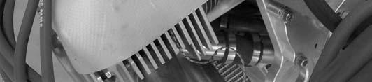


38 Ram air ducts fixed to engine with rocker cover cap screws front & rear. Oil cooler soft mounted on rubber grommets Torque on propeller bolts 6 Figure 15. Engine Installation #1 Air pipes direct cooling air from ram air ducts over coils. Figure 16. Coil Cooling Detail #1 Figure 17. Coil Cooling Detail #2 REVISION Dated : 19/09/2007 Page: 38 of 51
 Attach male engine mount rubbers to all engine mount pins on the engine mount.")
 With the Back of the Aircraft Supported & the wheels chocked, lift the engine onto the engine mount.")
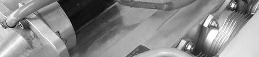
39 21.1 Engine Installation Procedure Male rubber engine mount Female rubber engine mount Washer engine mount Air duct Washer engine mount Lock wire to attach ram air cooling ducts. Rivet Propeller guide bush Spring mounting bracket Exhaust spring Belleville Washer Figure 18. Engine Accessory Pack Contents Procedure: a) Attach male engine mount rubbers to all engine mount pins on the engine mount. Place an AN4-31A bolt through each mount (see details below). Note that an engine mount spacer washer is fitted between the male rubber & the lower engine mount pins (Refer to Figure below). b) With the Back of the Aircraft Supported & the wheels chocked, lift the engine onto the engine mount. c) Insert the upper engine mount rubbers into the engine backing plate first by tilting the front of the engine up. Once both upper rubbers are through the engine backing plate, fit the female rubber, engine mount spacer washer, engine mount washer, ¼ washer & Heat Proof nut. d) To place the nuts on the mount bolts the rubbers must be compressed. Do this by using a deep reach socket inside the engine mount pins & clamping the rubber mount assembly using a G-clamp with the swivel taken off the ball. See Photo. Start nuts on both upper mount bolts. REVISION Dated : 19/09/2007 Page: 39 of 51

 Use the weight of the engine to compress the lower")

 The lower engine mount rubbers")


40 e) Once bolts of the upper rubbers are started, continue lowering the front of the engine & align the lower engine mount pins with the engine backing plate. f) Use the weight of the engine to compress the lower rubbers & fit the nuts to the bolts. Male engine mount rubber Engine backing plate Female engine mount rubber Engine mount Washer Heat proof nut Figure 19. Upper Engine Mount Detail g) The lower engine mount rubbers are assembled in the same way, except the male engine mount rubber is fitted to the engine mount pins first. Refer to drawing below. h) Tighten nuts until firm. (Engine mount washer will touch the engine mount pin as the rubbers compress) REVISION Dated : 19/09/2007 Page: 40 of 51


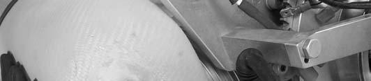
41 G-Clamp with swivel removed Deep long reach socket Figure 20 Lower Engine Mount Detail REVISION Dated : 19/09/2007 Page: 41 of 51
42 UPPER ENGINE MOUNT CONFIGURATION APPLICABLE JABIRU 2200, AND 3300 ENGINE INSTALLATIONS IN JABIRU AIRCRAFT LOWER ENGINE MOUNT CONFIGURATION APPLICABLE JABIRU 2200, AND 3300 ENGINE INSTALLATIONS IN JABIRU AIRCRAFT Figure 21. Engine Mount Detail REVISION Dated : 19/09/2007 Page: 42 of 51


.")
 Ensure the fuel line from fuel pump to the")
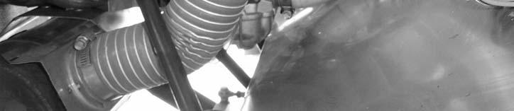
43 Fuel line from firewall fitting to mechanical fuel pump Fuel line from mechanical fuel pump to carburettor Fuel line from firewall fitting to fuel pump Figure 22. Fuel Connections General Fuel line from fuel pump to carburettor Fuel pump breather line to be vented overboard Figure 23. Fuel Connection Detail i) Connect the fuel line to fuel pump (Refer to photo). Ensure the fireproof sleeve is in place. j) Ensure the fuel line from fuel pump to the carburettor is connected & protected by fireproof sleeve. REVISION Dated : 19/09/2007 Page: 43 of 51

 Fit the oil over flow bottle to the firewall by drilling")
 Connect the oil breather line from the engine breather.")
 Fit Scat hoses from NACA duct to Air Inlet Housing Assembly, from hot air muff")

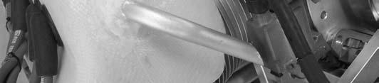
44 k) Ensure that the fuel overflow line is in place, and secured to vent overboard. Oil collector bottle Oil vent line from engine breather Oil vent line venting overboard Figure 24. Oil Collector Bottle l) Fit the oil over flow bottle to the firewall by drilling and Riveting oil bottle holder in place using 73AS 6-6 rivets. Refer to photo. m) Connect the oil breather line from the engine breather. n) Ensure that the oil overflow line is in place and vents overboard. o) Fit Scat hoses from NACA duct to Air Inlet Housing Assembly, from hot air muff to carburettor heat inlet on the hot air mixer box and from the hot air mixer box to carburetor. Note It is most important to remove any sharp edges or lips off the inside of the mixer box cover. See Photos below REVISION Dated : 19/09/2007 Page: 44 of 51


45 Incorrect plumbing Note sharp lips Figure 25. Hot Air Plumbing Incorrect Correct plumbing sharp lips & abrupt corners rounded & smoothed off. Figure 26 Hot Air Plumbing Correct REVISION Dated : 19/09/2007 Page: 45 of 51


46 SCAT hose from NACA inlet to mixer box SCAT hose from hot air muff on exhaust to mixer box Figure 27. SCAT Hose Detail #1 REVISION Dated : 19/09/2007 Page: 46 of 51
47 Figure 28. Typical Hot Air Mixer Box REVISION Dated : 19/09/2007 Page: 47 of 51
 Fit throttle cable to carburetor.")

 Fit choke cable to carburettor. Use an R-clip to assemble.")
48 Jabiru Aircraft Throttle cable connected Kit Throttle Cable Carburettor end Throttle lever end Figure 29. Control Connections to Carburettor p) Fit throttle cable to carburetor. Note that Jabiru Aircraft kits come with a throttle cable cut to length and with the correct end fitting attached. Engines used in firewall-forward kits will be supplied with a length of throttle cable with no end the builder must cut the cable to length and fit the carburettor end fitting. 5/16 washers are used on the cable end fitting (one washer either side of cable end fitting) to align cable. Use R-clip to assemble. q) Fit choke cable to carburettor. Use an R-clip to assemble. Note that the fuel line from the fuel pump to the carburettor passes between the choke and throttle cables. Choke cable not shown on Figure above. REVISION Dated : 19/09/2007 Page: 48 of 51


49 Balance tube connecting filtered side of air mixer box to nipple on carburettor. Figure 30. Balance Tube Detail #1 r) Connect the fuel balance tube from the nipple on the carburettor to a fitting on the filtered air side of the air mixer box. Note: The balance tube must be connected to ensure proper mixture control. Balance tube nipple Figure 31. Carburettor Balance Tube Nipple s) Fit cylinder head temperature (CHT) sensor. The CHT sensor used in Jabiru aircraft is a J-type thermocouple located under the rear spark plug of No: 4 cylinder. The VDO Cylinder Head Temperature Gauge Kit is compatible with this sensor and is installed as standard equipment in Jabiru Aircraft. Note that to ensure an accurate temperature reading it is important to have the cold junction for the CHT (the plug between the stiff thermocouple wires and the normal, plastic-insulated gauge wires) located away from the heat of the engine. Refer to Figure at the beginning of the engine installation section above. REVISION Dated : 19/09/2007 Page: 49 of 51
 The Oil Temperature Sensor used is a")


 The oil pressure sensor is located at the")
 The exhaust gas probe used on Jabiru engines is a")

50 Oil temperature sensor Figure 32. Oil Temperature Sensor t) The Oil Temperature Sensor used is a VDO which is located in the bottom of the sump as shown in photo. Wire WK is normally not used, but can be used to power a low oil pressure warning light. Oil pressure sender. Connect wire G to gauge Figure 33. Oil Pressure Sensor u) The oil pressure sensor is located at the base of the oil filter and this can be seen in photo. The sensor used is VDO v) The exhaust gas probe used on Jabiru engines is a VDO Pyrometer which is supplied as a complete kit. The probe is mounted in a fitting which is welded to an exhaust pipe. Note that this fitting is not standard. The installation of the fitting is REVISION Dated : 19/09/2007 Page: 50 of 51


51 best done at the time of order, though if required the exhaust pipe may be returned to Jabiru and the fitting added. Note that in this case it will normally take around 2 weeks before the pipe is returned to you. The fitting is welded to the pipe 100mm down from the exhaust manifold mounting plate. w) The Tachometer sensor used is a 6.35 x 22 mm analogue magnetic pick-up and is fitted to a bracket on the alternator housing. Refer to photo below. The sensor picks up on 2 tags fitted behind the flywheel. Tachometer Sensor Figure 34. Tachometer Sensor Installation. REVISION Dated : 19/09/2007 Page: 51 of 51
INSTALLATION MANUAL FOR JABIRU 2200 AIRCRAFT ENGINE
 INSTALLATION MANUAL FOR JABIRU 2200 AIRCRAFT ENGINE This Manual has been prepared as a guide to correctly install the Jabiru 2200 engine into an airframe. Should you have any questions or doubts about
INSTALLATION MANUAL FOR JABIRU 2200 AIRCRAFT ENGINE
 INSTALLATION MANUAL FOR JABIRU 2200 AIRCRAFT ENGINE This Manual has been prepared as a guide to correctly install the Jabiru 2200 engine into an airframe. Should you have any questions or doubts about
INSTALLATION MANUAL FOR JABIRU 5100 AIRCRAFT ENGINE
 INSTALLATION MANUAL FOR JABIRU 5100 AIRCRAFT ENGINE This Manual has been prepared as a guide to correctly install the Jabiru 5100 engine into an airframe. Should you have any questions or doubts about
INSTALLATION MANUAL FOR JABIRU 3300 AIRCRAFT ENGINE
 INSTALLATION MANUAL FOR JABIRU 3300 AIRCRAFT ENGINE This Manual has been prepared as a guide to correctly install the Jabiru 3300 engine into an airframe. Should you have any questions or doubts about
INSTALLATION MANUAL FOR JABIRU 3300 AIRCRAFT ENGINE. DOCUMENT No. JEM3302-4
 INSTALLATION MANUAL FOR JABIRU 3300 AIRCRAFT ENGINE DOCUMENT No. JEM3302-4 This Manual is a guide to correctly install the Jabiru 3300 engine into an airframe. If you have any questions or doubts about
INSTALLATION MANUAL FOR JABIRU 2200 AIRCRAFT ENGINE. DOCUMENT No. JEM2202-8
 INSTALLATION MANUAL FOR JABIRU 2200 AIRCRAFT ENGINE DOCUMENT No. JEM2202-8 This Manual is a guide to correctly install the Jabiru 2200 engine into an airframe. If you have any questions or doubts about
INSTALLATION MANUAL FOR JABIRU 5100 AIRCRAFT ENGINE. DOCUMENT No. JEM5103-1
 INSTALLATION MANUAL FOR JABIRU 5100 AIRCRAFT ENGINE DOCUMENT No. JEM5103-1 This Manual is a guide to correctly install the Jabiru 5100 engine into an airframe. If you have any questions or doubts about
INSTALLATION MANUAL FOR JABIRU 3300 AIRCRAFT ENGINE. DOCUMENT No. JEM3302-7
 INSTALLATION MANUAL FOR JABIRU 3300 AIRCRAFT ENGINE DOCUMENT No. JEM3302-7 This Manual is a guide to correctly install the Jabiru 3300 engine into an airframe. If you have any questions or doubts about
11. Completing the Fuselage Engine Installation
 11. Completing the Fuselage Engine Installation Engine Installations 11 1 230399 - Fit Engine Mount Reference: Photo 11.16(a) Parts Required: 4025094 Backing Plate Engine Mount (4) AN4-20A Bolt (4) AN3-11A
JABIRU AIRCRAFT PTY LTD P.O. Box 5186 Phone: Bundaberg West Fax: Queensland, Australia.
 JABIRU AIRCRAFT PTY LTD P.O. Box 5186 Phone: +61 7 4155 1778 Bundaberg West Fax: +61 7 4155 2669 Queensland, Australia. Email: info@jabiru.net.au SERVICE BULLETIN: JSB 018-1 Issue: 1 Date: 5 th October
Jabiru Aircraft Pty. Ltd. Final Inspection Checklist J200/400. Firewall forward components
 Jabiru Aircraft Pty. Ltd. Final Inspection Checklist J200/400 Registration No: Aircraft Checklist Pre Ground Test Model: Aircraft Serial No: Firewall forward components Propeller: Prop Size: 60 x 53 Other:
INSTRUCTION AND MAINTENANCE MANUAL FOR JABIRU 5100 AIRCRAFT ENGINE. DOCUMENT No. JEM5101-3
 INSTRUCTION AND MAINTENANCE MANUAL FOR JABIRU 5100 AIRCRAFT ENGINE DOCUMENT No. JEM5101-3 This Manual has been prepared as a guide to correctly operate, maintain and Service the Jabiru 5100 engine. It
Wires banded White are from Sensors or Pick-ups to Sensor positions on components of the Aircraft systems.
 Electrical Wiring Reference: Drawing 9451061, Diagrams 1 to 14 Photo Parts Required: As Detailed Materials Required: As Detailed Procedure: All wires should be colour coded in the following way: Wires
JABIRU ENGINE PARTS BOOK SERIES From Serial Number 22A225. Applicable to Jabiru 2200A, 2200B & 2200J Models
 JABIRU ENGINE PARTS BOOK 2200 SERIES From Serial Number 22A225 Applicable to Jabiru 2200A, 2200B & 2200J Models Jabiru Aircraft Pty Ltd ACN 010 910 077 PO Box 5186 Bundaberg Australia 4670 Australia: Phone
Jabiru Aircraft Pty. Ltd. Final Inspection Checklist. Engine Compartment
 Jabiru Aircraft Pty. Ltd. Final Inspection Checklist Registration No: Aircraft Checklist Pre Ground Test Model: Serial No: Engine Compartment Propeller: Prop Size: 60 x 53 Other:.. Propeller Serial No:
Counter-clockwise, view to output shaft Mixture 1:50, 2-stroke-oil, fuel min. 95 octane (RON)
") HIRTH 2703 Carburated - 55 hp The 2703 V is an air cooled, piston controlled 2-cylinder-inline-2-stroke engine with one or two carburetors and Nikasil coated cylinders. It has one of the highest power
HIRTH 2703 Carburated - 55 hp The 2703 V is an air cooled, piston controlled 2-cylinder-inline-2-stroke engine with one or two carburetors and Nikasil coated cylinders. It has one of the highest power
JABIRU ENGINE PARTS BOOK 3300 SERIES HYDRAULIC LIFTER TYPE
 JABIRU ENGINE PARTS BOOK 3300 SERIES HYDRAULIC LIFTER TYPE Applicable to Jabiru 3300 Models from S/N 33A961 onwards (including 33A927, 33A928, 33A947, 33A948, 33A949, 33A950) Jabiru Aircraft Pty Ltd ACN
Accident Prevention Program
 Accident Prevention Program Part I ENGINE OPERATION FOR PILOTS by Teledyne Continental Motors SAFE ENGINE OPERATION INCLUDES: Proper Pre-Flight Use the correct amount and grade of aviation gasoline. Never
HIRTH 2703 Carburated - 55 hp
 HIRTH 2703 Carburated - 55 hp The 2703 V is an air cooled, piston controlled 2-cylinder-inline-2-stroke engine with one or two carburetors and Nikasil coated cylinders. It has one of the highest power
CIRRUS AIRPLANE MAINTENANCE MANUAL
 POWER PLANT 1. GENERAL This chapter describes maintenance practices for the airplane systems which provide the means to induce and convert fuel-air mixture into power such as the engine, baffling, cowling,
HIRTH 3203 Carburated - 65 hp
 HIRTH 3203 Carburated - 65 hp 2706-65Hp engine shown with fan cooling HIRTH s most popular engine. The 3203 produces more horsepower and torque per pound than any other engine in its power class. Hirth
Instruction Manual SPE-26CC
 Instruction Manual SPE-26CC 1 Safety Precautions This engine is for experienced flyers only and could cause serious harm if used incorrectly. Always take care when running large gas engines. Read this
UNCONTROLLED COPY DATE: JSB 004-4
 Page 1 of 8 SERVICE BULLETIN: Issue: 4 Subject: Affected S/No: Changes from previous issue shown in red text. Issue 1 (JSB004-1) Released 13 th Oct 2004 Issue 2 (JSB004-2) Released 6 th Dec 2004 Issue
O-360 & IO-360 Series Model Specification Summary
 O-360 & IO-360 Series Model Specification Summary 621 South Royal Lane, Suite 100 / Coppell, TX 75019 / 800-277-5168 www.superior-air-parts.com Technical Data Summary Design Highlights O-360 IO-360 Rating
AN EXPLANATION OF CIRCUITS CARTER YH HORIZONTAL CLIMATIC CONTROL CARBURETER
 AN EXPLANATION OF CIRCUITS CARTER YH HORIZONTAL CLIMATIC CONTROL CARBURETER The Carter Model YH carbureter may be compared with a Carter YF downdraft carbureter with the circuits rearranged to operate
Induction, Cooling, & Exhaust. Aviation Maintenance Technology 111 B B
 Induction, Cooling, & Exhaust Aviation Maintenance Technology 111 B - 112 B Unliscensed copyrighted material - W. North 1998 Unliscensed copyrighted material - W. North 1998 Induction = those locations
Service Instruction ENGINE COMPONENTS, INC.
 Title: Service Instruction S.I. No.: 89-5-1 Page: 1 of 5 Issued: 05/05/89 Revision: 1 (09/01/01) Technical Portions of FAA DER Approved. FAILURE OF ENGINE TO START 27 points 1. Lack of fuel 2. Ignition
EDELBROCK THUNDER SERIES AVS CARBURETORS Part #1801, 1802, 1803, 1804, 1805, 1806, 1812, 1813, 1825, 1826 INSTALLATION INSTRUCTIONS
 EDELBROCK THUNDER SERIES AVS CARBURETORS Part #1801, 1802, 1803, 1804, 1805, 1806, 1812, 1813, 1825, 1826 INSTALLATION INSTRUCTIONS IMPORTANT NOTE: Proper installation is the responsibility of the installer.
Typical Install Instructions
 Typical Install Instructions Read & understand all steps of these instructions before beginning this installation. WEBER Conversion Kit, VW T-1/2, up to 1835cc 32 / 36 DFEV Weber Carburetor These instructions
Maintenance Instruction 23.1
 Subject: Replacement of engine GROB 2500 E1/D1 by engine LIMBACH L 2400 EB1.AA Affected Aircraft: Motor glider GROB G 109 (B) Aircraft: Type G 109 (B) Registration Propeller: Type MTV-1-A/L160-03 Serial
9/7/2014 F9.9MSHV 1997 / CYLINDER CRANKCASE Yamaha Motor Corporation, U.S.A. All rights reserved.
 F9.9MSHV 997 Page of 45 9/7/04 F9.9MSHV 997 / CYLINDER CRANKCASE 04 Yamaha Motor Corporation, U.S.A. All rights reserved. F9.9MSHV 997 Page of 45 9/7/04 Part List F9.9MSHV 997 / CYLINDER CRANKCASE REF
CARBURETOR SERVICE INFORMATION TROUBLESHOOTING THROTTLE VALVE DISASSEMBLY THROTTLE VALVE INSTALLATION...
 11 CARBURETOR SERVICE INFORMATION... 11-2 TROUBLESHOOTING... 11-2 THROTTLE VALVE DISASSEMBLY... 11-3 THROTTLE VALVE INSTALLATION... 11-4 CARBURETOR REMOVAL... 11-5 AUTO BYSTARTER... 11-6 FLOAT CHAMBER...
For Discount Tecumseh Engine Parts Call or V J Page 1 of 8 Engine Parts List #1
 V60-70346J Page 1 of 8 Engine Parts List #1 V60-70346J Page 2 of 8 Engine Parts List #1 1 34177 0 Cylinder Assy. (2-5/8" Bore) 2 27652 0 Pin, Dowel 3 31461 0 Bushing, Crankshaft 4 27876B 0 Seal, Oil 5
WEBER CARBURETOR TROUBLESHOOTING GUIDE
 This guide is to help pinpoint problems by diagnosing engine symptoms associated with specific vehicle operating conditions. The chart will guide you step by step to help correct these problems. For successful
SECTION 6A1-2 - ENGINE MECHANICAL - V6 SUPERCHARGED
 SECTION 6A1-2 - ENGINE MECHANICAL - V6 SUPERCHARGED CAUTION: This vehicle will be equipped with a Supplemental Restraint System (SRS). A SRS will consist of either seat belt pre-tensioners and a driver
9/7/2014 T9.9ELRZ 2001 / TOP COWLING Yamaha Motor Corporation, U.S.A. All rights reserved.
 T9.9ELRZ 00 Page of 56 9/7/0 T9.9ELRZ 00 / TOP COWLING 0 Yamaha Motor Corporation, U.S.A. All rights reserved. T9.9ELRZ 00 Page of 56 9/7/0 Part List T9.9ELRZ 00 / TOP COWLING REF - NO PART NUMBER PART
2005 Manufactured exclusively for Horizon Hobby, Inc
 2005 Manufactured exclusively for Horizon Hobby, Inc. www.horizonhobby.com 800-535-5551 7795 Evolution Engines 26GT/35GT USER GUIDE Before using this engine, please read these instructions carefully. Introduction
SPECIFICATIONS TEST AND ADJUSTMENT SPECIFICATIONS SPECIFICATIONS ENGINE FD620D, K SERIES
 TEST AND ADJUSTMENT Engine Oil Pressure Sensor Activates............................... 98 kpa (14.2 psi) Oil Pressure While Cranking (Minimum).......................... 28 kpa (4 psi) Oil Pressure.....................................
service bulletin MCM 4.3L, 4.3LX Alpha GM Generation II Engine Specifications No
 service bulletin TO: SERVICE MANAGER MECHANICS PARTS MANAGER No. 91-17 MCM 4.3L, 4.3LX Alpha GM Generation II Engine Specifications NOTE: These engines have an electric fuel pump because there is no pad
MAINTENANCE MANUAL FOR JABIRU 2200 Gen 4 AIRCRAFT ENGINE JABIRU 3300 Gen 4 AIRCRAFT ENGINE. DOCUMENT No. JEM DATED: 16 th October 2017
 MAINTENANCE MANUAL FOR JABIRU 2200 Gen 4 AIRCRAFT ENGINE JABIRU 3300 Gen 4 AIRCRAFT ENGINE DOCUMENT No. DATED: 16 th October 2017 This Manual has been prepared as a guide to correctly operate, maintain
AIRCRAFT GENERAL KNOWLEDGE (1) AIRFRAME/SYSTEMS/POWERPLANT
 AIRFRAME/SYSTEMS/POWERPLANT") 1 In flight, a cantilever wing of an airplane containing fuel undergoes vertical loads which produce a bending moment: A highest at the wing root B equal to the zero -fuel weight multiplied by the span
1 In flight, a cantilever wing of an airplane containing fuel undergoes vertical loads which produce a bending moment: A highest at the wing root B equal to the zero -fuel weight multiplied by the span
Information on new developments on ROTAX ultralight engines
 Information on new developments on ROTAX ultralight engines 1) Engine type 582 The water-cooled ultralight engine type 532 has been most popular over many years and is installed in numerous ultralights.
JABIRU AIRCRAFT PTY LTD P.O. Box 5186 Phone: Bundaberg West Fax: Queensland, Australia.
 JABIRU AIRCRAFT PTY LTD P.O. Box 5186 Phone: +61 7 4155 1778 Bundaberg West Fax: +61 7 4155 2669 Queensland, Australia. Email: info@jabiru.net.au SERVICE BULLETIN: JSB 014-1 Issue: 1 Date: 30 th October
service bulletin MCM 7.4L Bravo, MIE 7.4L Inboard GM Generation V Engine Specifications No. 91-6
 service bulletin TO: SERVICE MANAGER MECHANICS PARTS MANAGER No. 91-6 MCM 7.4L Bravo, MIE 7.4L Inboard GM Generation V Engine Specifications NOTE: Generation V Engines Have the Fuel Pump Mounted on the
INDEX INTRODUCTION. Reference No L-01 REVISED:
 12-21L-01 1 1 INTRODUCTION We are constantly working on technical improvement of our products. For this reason, technical data, equipment and design are subject to change without notice. All specifications
SDS Continental O-200 Installation Manual Aug. 4/17
 SDS Continental O-200 Installation Manual Aug. 4/17 This manual covers the steps to install the SDS EM-5 fuel injection and ignition system components on O-200 engines. Hall Sensor and Bracket Install
HIRTH ENGINE SETTING VALUES. 55 HP Engine Fan cooled engine
 HIRTH ENGINE SETTING VALUES 55 HP Engine Fan cooled engine Engine 55HP FC Ign. Timing @ 2000 Carbureted 14 BTC Spark Plug Heat VI * 280 Spark Plug Gap.020-.024 No. of Carburetors Two Carburetor ID # Bing
SECTION 4 - FUEL SYSTEMS AND CARBURETION
 SECTION - FUEL SYSTEMS AND CARBURETION FUEL SYSTEMS - - - - - - - - - - - - - - - - - - - - - - - - - - - - - - - - - - - - - - - - - - - - - - - - - - - - - - - - - - - - - -62 FUEL PUMP - - - - - - -
Tuning A Walbro Carb. Walbro Carb TUNE UP & Illustrated Guide
 Tuning A Walbro Carb Walbro Carb TUNE UP & Illustrated Guide by M. B. Fuess Walbro carbs aren t too difficult to tune up if you know what you re doing. First of all, you need to know how the carb works
TECHNICAL DATA. COMPRESSION RATUI 9,5/1 WEIGHT ready to fly CONSUMPTION at 5400RPM 5,6litres/h POWER at 6200RPM
 VICTOR 1 SUPER This handbook aims to bring to the attention of key technical, functional and maintenance of your motor VICTOR 1. Read carefully the following pages, will be synonymous with safety, reliability
SPECIFICATIONS TEST AND ADJUSTMENT SPECIFICATIONS SPECIFICATIONS ENGINE FD620D, K SERIES
 ENGINE FD620D, K SERIES SPECIFICATIONS SPECIFICATIONS TEST AND ADJUSTMENT SPECIFICATIONS Engine Oil Pressure Sensor Activates............................... 98 kpa (14.2 psi) Oil Pressure While Cranking
400 4x4 Euro MODEL NUMBER A2008IDG4BEUR (RED) MODEL NUMBER A2008IDG4BEUG (GREEN) MODEL NUMBER A2008IDG4BEUZ (CAT GREEN) MORE TO GO ON.
 MODEL NUMBER A2008IDG4BEUG (GREEN) MODEL NUMBER A2008IDG4BEUZ (CAT GREEN) MORE TO GO ON.") 2008 400 4x4 Euro Illustrated Parts Manual MODEL NUMBER A2008IDG4BEUR (RED) MODEL NUMBER A2008IDG4BEUG (GREEN) MODEL NUMBER A2008IDG4BEUZ (CAT GREEN) MORE TO GO ON. TM TABLE OF CONTENTS 2008 ATV 400 4x4
2008 400 4x4 Euro Illustrated Parts Manual MODEL NUMBER A2008IDG4BEUR (RED) MODEL NUMBER A2008IDG4BEUG (GREEN) MODEL NUMBER A2008IDG4BEUZ (CAT GREEN) MORE TO GO ON. TM TABLE OF CONTENTS 2008 ATV 400 4x4
Lycoming Engine Sender Installation Guide
 3401 Airport Drive Ste E, Torrance, CA 90505. Tel: 1-877-8FLYING Fax: 1-310-534-2282 e-mail: sales@mglavionics.com Web: www.mglavionics.com MGL Avionics EFIS Lycoming Engine Sender Installation Guide This
MAINTENANCE MANUAL FOR JABIRU 2200 AIRCRAFT ENGINE JABIRU 3300 AIRCRAFT ENGINE. DOCUMENT No. JEM DATED: 30 th June 2016
 MAINTENANCE MANUAL FOR JABIRU 2200 AIRCRAFT ENGINE JABIRU 3300 AIRCRAFT ENGINE DOCUMENT No. 7 DATED: 30 th June 2016 This Manual has been prepared as a guide to correctly operate, maintain and service
Illustrated Parts Catalogue
 Illustrated Parts Catalogue UL26Oi/iF/iS AERO ENGINE M00: IPC 260A0 Revision No : 0 Date: 207-0-9 Please fill in your engine and aircraft details for further reference: Engine Serial No. :... Aircraft
GP 123. Great Power Model Engines
 Great Power Model Engines www.gp-engine.com.tw GP 123 Displacement: 123C.C Output: 13hp Bore: 46.5mm Weight: 2300g RPM Range: 1000~7200 Recommend Gasoline Octane Number: 89~92 (R+M)/2) Warranty: 2 years
Illustrated Parts List
 FORM MS 2263 12/08/2004 REPLACES FORM MS 2263 03/20/2004 FILE IN SECT. 2 OF SERVICE MANUAL Illustrated Parts List Model Series TYPE NUMBERS 0001 through 1421. TABLE OF CONTENTS Air Cleaners........................
Test Flying should only be performed by a pilot who is licensed, rated and experienced on the aircraft type.
 Test Flying Procedure: Test Flying should only be performed by a pilot who is licensed, rated and experienced on the aircraft type. In particular, the test pilot should have recently demonstrated an ability
EMS Installation Instructions
 EMS Installation Instructions The EMS1 and EMS2 are functionally identical and, as such, their installation is identical. Both EMS versions use the same connector as follows: EMS1 Walk-through video on
Illustrated Parts List
 FORM MS 2264 07/20/2005 REPLACES FORM MS 2264 03/04/2005 FILE IN SECT. 2 OF SERVICE MANUAL 350700 Illustrated Parts List Model Series 350700 TYPE NUMBERS 0034 through 1171. TABLE OF CONTENTS Air Cleaner.........................
ATV 300 DVX CAT GREEN (A2011KSF2BUSZ) Page 1 of 56 AIR INTAKE ASSEMBLY
 Page 1 of 56 AIR INTAKE ASSEMBLY") 2011 ATV 300 DVX CAT GREEN (A2011KSF2BUSZ) Page 1 of 56 AIR INTAKE ASSEMBLY 2011 ATV 300 DVX CAT GREEN (A2011KSF2BUSZ) Page 2 of 56 AIR INTAKE ASSEMBLY Ref # Part Number Qty S/P/F Description 1 3303-705
2011 ATV 300 DVX CAT GREEN (A2011KSF2BUSZ) Page 1 of 56 AIR INTAKE ASSEMBLY 2011 ATV 300 DVX CAT GREEN (A2011KSF2BUSZ) Page 2 of 56 AIR INTAKE ASSEMBLY Ref # Part Number Qty S/P/F Description 1 3303-705
Introduction WISCONSIN ROBIN WR-WOI-21 OPM REV DATE: This catalog is designed to identify Wisconsin Robin parts.
 WISCONSIN ROBIN WR-WOI- OPM REV DATE: 0- Introduction This catalog is designed to identify Wisconsin Robin parts. When ordering parts, it is always advisable to list the engine model, specification number
Illustrated Parts List
 FORM MS 0670 3C 8/2001 REPLACES FORM MS 0670 2Q 11/2000 FILE IN SECT. 2 OF SERVICE MANUAL Illustrated Parts List Model Series TYPE NUMBERS 0042 through 1256. For Use On Engines Built Before Date Code 01070100.
WORKSHOP MANUAL. 63,4 cm³ chainsaws
 WORKSHOP MANUAL General failures analysis Suggested tools I. Emak tool kit II. Compression tester: to check thermal group III. Electronic tachometer: for 2 and 4 stroke engines, measurement range from
Operation and Maintenance Instructions for the RAPTOR 178
 WWW.SKYTOY.COM Operation and Maintenance Instructions for the RAPTOR 178 See www.skytoy.com for updates and service bulletins. 2/1/2011 1. Parts Schematic:... 3 2. Muffler Assembly Diagram:... 4 3. Muffler
Robinson R44. Systems
 Robinson R44 Systems The airframe is primarily a metal construction. The primary fuselage is welded steel tubing and riveted aluminium sheet. The tailcone is an aluminium semi-monocoque structure where
DEPARTMENT OF TRANSPORTATION FEDERAL AVIATION ADMINISTRATION TYPE CERTIFICATE DATA SHEET NO. 1E12
 DEPARTMENT OF TRANSPORTATION FEDERAL AVIATION ADMINISTRATION TYPE CERTIFICATE DATA SHEET NO. 1E12 1E12 Revision 9 Lycoming Engines IO-320 -A1A-A2A-B1A, -B1B, B1C, -B1E, -B1D, -B2A, -C1A, -C1B, -D1A, -D1C,
SDS Continental IO-550 Installation Manual
 SDS Continental IO-550 Installation Manual July14/18 This manual covers the steps to install the SDS EM-5 fuel injection and ignition system components on IO-550 engines. Checking Clearance for Hall Sensor
Part #82064 Add-A-Stage EFI Nitrous System
 1 INSTRUCTIONS Part #82064 Add-A-Stage EFI Nitrous System Thank you for choosing products; we are proud to be your manufacturer of choice. Please read this instruction sheet carefully before beginning
E70PL4EEC 1999 : CAMSHAFT [1/23] Page 1 of 49
![E70PL4EEC 1999 : CAMSHAFT [1/23] Page 1 of 49](/thumbs/96/129257940.jpg "E70PL4EEC 1999 : CAMSHAFT [1/23] Page 1 of 49") E70PL4EEC 1999 : CAMSHAFT [1/23] Page 1 of 49 E70PL4EEC 1999 : CAMSHAFT [1/23] 1 5030657 1 CAMSHAFT 2 5030658 1 PLATE, Camshaft thrust 3 5030549 1 SEAL, Camshaft 4 5030989 2 BOLT, Plate 5 5030663 8 ARM,
E70PL4EEC 1999 : CAMSHAFT [1/23] Page 1 of 49 E70PL4EEC 1999 : CAMSHAFT [1/23] 1 5030657 1 CAMSHAFT 2 5030658 1 PLATE, Camshaft thrust 3 5030549 1 SEAL, Camshaft 4 5030989 2 BOLT, Plate 5 5030663 8 ARM,
13. FUEL SYSTEM/CARBURETOR/
 13 FUEL SYSTEM/CARBURETOR/FUEL PUMP FUEL SYSTEM --------------------------------------------------------- 13-1 SCHEMATIC DRAWING ---------------------------------------------- 13-2 OPERATION OF CARBURETOR
S/N 1H019H - 1H310H Page 1 of 48 42" Cutting Deck Assembly
 1170 S/N 1H019H - 1H310H Page 1 of 48 42" Cutting Deck Assembly 1170 S/N 1H019H - 1H310H Page 2 of 48 42" Cutting Deck Assembly 4 683-0254 1 S Deck Adjustment Bracket w/ Weld Nut 9 710-0528 1 /P Hex Cap
235/245400, , 28N
 Models 235/245400, 287000, 28N thru W, 310/312/313700 These carburetors have a fixed high speed main jet with adjustable idle, Fig 183. The different carburetors are identified as LMT 1 and up. The letters
1.8L & 2.2L 4-CYL Article Text 1998 Subaru Impreza
 1.8L & 2.2L 4-CYL Article Text 1998 Subaru Impreza ARTICLE BEGINNING 1995-98 ENGINES Subaru - 1.8L & 2.2L 4-Cylinder 1995-97: Impreza (1.8L) 1995-98: Impreza (2.2L), Legacy (2.2L) * PLEASE READ THIS FIRST
POLARIS MARINE 1200 Model #W000099D Polaris Sales Inc. PARTS MANUAL PN and MICROFICHE PN /00
 POLARIS MARINE 00 Model #W000099D 000 Polaris Sales Inc. PARTS MANUAL PN 9968 and MICROFICHE PN 9969 /00 TABLE OF CONTENTS POLARIS MARINE 00 W000099D Parts Manual A AIR VENT...........................
DIRECTIONS FOR USING ZDZ ENGINES
 DIRECTIONS FOR USING ZDZ ENGINES (Please READ this carefuly and become FAMILIAR with these instructions before using the engine) ZDZ two-stroke gasoline engines are intended for large models and offer
14A6816H190 GT-2150 (2003) Page 1 of 28 Carburetor
 Page 1 of 28 Carburetor") 14A6816H190 GT-2150 (2003) Page 1 of 28 Carburetor 14A6816H190 GT-2150 (2003) Page 2 of 28 Carburetor TC-640221 1 /P Carburetor (Incl 184 of Engine Parts Lists) 1 TC-640216 1 Throttle Shaft & Lever Assembly
14A6816H190 GT-2150 (2003) Page 1 of 28 Carburetor 14A6816H190 GT-2150 (2003) Page 2 of 28 Carburetor TC-640221 1 /P Carburetor (Incl 184 of Engine Parts Lists) 1 TC-640216 1 Throttle Shaft & Lever Assembly
71253, XL 440H Lawn Tractor, 2008 (SN ) : BLOWER HOUSING ASSEMBLY BRIGGS AND STRATTON MODEL 31P E1 [1/
 : BLOWER HOUSING ASSEMBLY BRIGGS AND STRATTON MODEL 31P E1 [1/") 71253, XL 440H Lawn Tractor, 2008 (SN 280000001-280999999) : BLOWER HOUSING ASSEMBLY BRIGGS AND STRATTON MODEL 31P777-0133-E1 [1/ Page 1 of 50 71253, XL 440H Lawn Tractor, 2008 (SN 280000001-280999999)
71253, XL 440H Lawn Tractor, 2008 (SN 280000001-280999999) : BLOWER HOUSING ASSEMBLY BRIGGS AND STRATTON MODEL 31P777-0133-E1 [1/ Page 1 of 50 71253, XL 440H Lawn Tractor, 2008 (SN 280000001-280999999)
World Formula TECH MANUAL
 World Formula TECH MANUAL Section 1 General Rules 1. Only stock Briggs & Stratton World Formula Model # 124435-8101 will be used in this class except as provided in this Tech manual. All parts will be
Installing and Adjusting Cooling Baffles. Duct and Air Dam Construction. Firewall-Forward Instruction Manual--General
 Firewall-Forward Instruction Manual--General Installing and Adjusting Cooling Baffles Like most air-cooled engines, Jabiru engines rely on ram air moving through a properly-constructed air duct for adequate
EDELBROCK THUNDER SERIES AVS CARBURETORS Part #1801, 1802, 1803, 1804, 1805, 1806, 1812, 1813, 1825, 1826 INSTALLATION INSTRUCTIONS
 EDELBROCK THUNDER SERIES AVS CARBURETORS Part #1801, 1802, 1803, 1804, 1805, 1806, 1812, 1813, 1825, 1826 INSTALLATION INSTRUCTIONS PLEASE study these instructions carefully before beginning this installation.
Jabiru 4 Cylinder 2200cc Engine.
 JABIRU ENGINE PARTS BOOK Jabiru 4 Cylinder 2200cc Engine. Jabiru Aircraft Pty Ltd ACN 010 910 077 PO Box 5792 Bundaberg Australia 4670 Australia: Phone 07 4155 1778 Fax 07 4155 2669 International: Phone
Owners Manual. Table of Contents 3.1. INTRODUCTION AIRSPEEDS FOR EMERGENCY OPERATION OPERATIONAL CHECKLISTS 3
 EMERGENCY PROCEDURES Table of Contents 3.1. INTRODUCTION 2 3.2. AIRSPEEDS FOR EMERGENCY OPERATION 2 3.3. OPERATIONAL CHECKLISTS 3 3.3.1. ENGINE FAILURES 3. ENGINE FAILURE DURING TAKEOFF RUN 3. ENGINE FAILURE
12. CARBURETOR/FUEL PUMP
 12 CARBURETOR/FUEL PUMP SERVICE INFORMATION... 12-2 TROUBLESHOOTING... 12-2 THROTTLE VALVE DISASSEMBLY... 12-3 THROTTLE VALVE INSTALLATION... 12-4 CARBURETOR REMOVAL... 12-5 AUTO BYSTARTER... 12-6 FLOAT
5. FUEL SYSTEM 5-0 FUEL SYSTEM MXU 250R/300R
 5 FUEL SYSTEM 5 SERVICE INFORMATION------------------------------------------------ 5-2 TROUBLESHOOTING----------------------------------------------------- 5-3 FUEL TANK -----------------------------------------------------------------
SERVICE DATA GT-220ES SRM-220ES TRIMMER/BRUSHCUTTER. (Serial nember : and after) (Serial nember : and after) INDEX INTRODUCTION
 (Serial nember : and after) INDEX INTRODUCTION") 10-21P-02, 1 1 SERVICE DATA TRIMMER/BRUSHCUTTER INTRODUCTION We are constantly working on technical improvement of our products. For this reason, technical data, equipment and design are subject to change
10-21P-02, 1 1 SERVICE DATA TRIMMER/BRUSHCUTTER INTRODUCTION We are constantly working on technical improvement of our products. For this reason, technical data, equipment and design are subject to change
Chapter 2. ENGINE DESCRIPTION CONTENTS. Chapter 2. Engine Description General Engine Description...2-3
 Teledyne Continental Motors, Inc. Chapter 2. ENGINE DESCRIPTION CONTENTS Chapter 2....2-1 2-1. General...2-3 2-1.1. Engine Model Number Definition... 2-5 2-1.2. Cylinder Number Designations... 2-5 2-2.
SERVICE DATA CHAIN SAW ECHO: CS-500ES STAGE MODEL. (Serial number : and after) CONTENTS INTRODUCTION
 CONTENTS INTRODUCTION") 01-50D-01 1 0 SERVICE DATA CHAIN SAW ECHO: STAGE MODEL (Serial number : 37000001 and after) INTRODUCTION We are constantly working on technical improvement of our products. For this reason, technical data,
01-50D-01 1 0 SERVICE DATA CHAIN SAW ECHO: STAGE MODEL (Serial number : 37000001 and after) INTRODUCTION We are constantly working on technical improvement of our products. For this reason, technical data,
Mid Size Traction Unit
 FORM NO. 3318 701 ProLine Mid Size Traction Unit 18 H.P. Kohler Gear Drive Model No. 30183 790001 & Up Parts Catalog 3318 701 ORDERING REPLACEMENT PARTS To order replacement parts, please supply: the part
For Experimental Aircraft Only: Glastar, Sportsman 2+2, and Similar with Lycoming O320 or O360 Parallel Valve Engines
 REPORT NAME: KIT PFS-16104 INSTALLATION INSTRUCTIONS AND INSTRUCTIONS FOR CONTINUED AIRWORTHINESS APPROVAL PFS ENG DATE: REPORT NUMBER: PFS-16250-EXP REVISION: A REPORT DATE: 02/14/06 PREPARED BY: Tom
S/N 1H019H - 1H310H Page 1 of 33 46" Cutting Deck Assembly
 1180 S/N 1H019H - 1H310H Page 1 of 33 46" Cutting Deck Assembly 1180 S/N 1H019H - 1H310H Page 2 of 33 46" Cutting Deck Assembly 1 17982 1 S Reinforcement Spindle Plate 2 618-0430 1 S Spindle Assembly w/
For Discount Tecumseh Engine Parts Call or HH E Page 1 of 8 Engine Parts List #1
 HH60-105080E Page 1 of 8 Engine Parts List #1 HH60-105080E Page 2 of 8 Engine Parts List #1 1 34761 0 Cylinder Assy. (Cast iron liner) (2-5/8" 2 27652 0 Pin, Dowel 3 27642 0 Plug, Drain 4 27876B 0 Seal,
WORKSHOP MANUAL. Chainsaw GS35 GS350 MT350 MT3500
 WORKSHOP MANUAL Chainsaw GS35 GS350 MT350 MT3500 General failures analysis Suggested tools I. Emak tool kit II. Compression tester: to check thermal group III. Electronic tachometer: for 2 and 4 stroke
C40008 & C40009 EXHAUST BRAKES
 EXHAUST BRAKES C40008 & C40009 1995 2003 Ford F250 / F350 7.3 L Powerstroke Diesel with manual transmissions 1995 1998 Ford F250 / F350 7.3 L Powerstroke Diesel with automatic transmission* *Requires the
14-6. TSB Revision ENGINE COOLING ON-VEHICLE SERVICE
 14-6 RADIATOR CAP DRAIN PLUG ENGINE COOLING ON-VEHICLE SERVICE When removing the radiator cap, use care to avoid contact with hot coolant or steam Place a shop towel over the cap and turn the cap counterclockwise
400 2x4/4x4 EFT SHARE OUR PASSION ṬM
 SHARE OUR PASSION ṬM 400 2x4/4x4 EFT Model Number A2009IDG2BETR (Red - 2x4) Model Number A2009IDG2BETZ (Cat Green - 2x4) Model Number A2009IDG4BETR (Red - 4x4) Model Number A2009IDG4BETG (Green - 4x4)
00-36A-04 CS-350T, CS-350TES, CS-350WES 1
 00-36A-04,, 1 0 INTRODUCTION We are constantly working on technical improvement of our products. For this reason, technical data, equipment and design are subject to change without notice. All specifications,
For Discount Tecumseh Engine Parts Call or V H Page 1 of 8 Engine Parts List #1
 V60-70291H Page 1 of 8 Engine Parts List #1 V60-70291H Page 2 of 8 Engine Parts List #1 1 33361A 0 Cylinder Assy. (2-5/8" Bore) 2 27652 0 Pin, Dowel 3 31461 0 Bushing, Crankshaft 4 27876B 0 Seal, Oil 5
Installation Instructions Dual Perimeter Plate Nitrous System (#82185)
") Installation Instructions Dual Perimeter Plate Nitrous System (#82185) Thank you for choosing ZEX. If at any time you have questions regarding this or any of our products, please call our ZEXTEK support
Installation Instructions Dual Perimeter Plate Nitrous System (#82185) Thank you for choosing ZEX. If at any time you have questions regarding this or any of our products, please call our ZEXTEK support