Formation of Soft Particles in Drop-in Fuels
|
|
|
- Ralph Hill
- 5 years ago
- Views:
Transcription

1 Formation of Soft Particles in Drop-in Fuels Richard A. Alim Master s Thesis Project KTH Royal Institute of Technology Engineering Sciences in Chemistry, Biotechnology, and Health

2 Formation of Soft Particles in Drop-in Fuels Richard A. Alim Supervisor: Henrik Hittig Examiner: Lars J. Pettersson
3 Abstract As the mission to the decrease global warming and phase out highly polluting environmental practices globally, regulations including Euro 6 and policies generated by the United Nations Framework Convention on Climate Change (UNFCCC) are pushing companies to be more innovative when it comes to their energy sources. These regulations involve many factors related to the cleanliness of the fuel and produced emissions, for example, properties of the fuels such as sulfur content, ash content, water content, and resulting emission values of Carbon dioxide (CO 2 ) and Nitrogen Oxides (NO x ). Furthermore, Sweden has set a challenging target of a fossil-fuel-independent vehicle fleet by 2030 and no net greenhousegas emissions by One way to cut down on the polluting properties in the fuel, as well as weakening the dependence on fossil fuel based fuel includes utilizing higher blending ratios of biofuels in the transport sector. This transition to biofuels comes with many challenges to the transport industry due to higher concentrations of these new fuels leads to clogging of the filters in the engine, as well as, internal diesel injector deposits (IDIDs) that produce injector fouling. This clogging of the filters leads to lower performance by the engines which leads to higher repair times (uptime) and less time on the road to transport goods. The formation of these soft particles at the root of the clogging issue is a pivotal issue because the precise mechanisms behind their formation are highly unknown. Scania, a leader in the Swedish automotive industry, is very interested in figuring out what mechanisms are the most influential in the formation of these particles in the engine. Understanding the key mechanisms would allow Scania to make appropriate adjustments to the fuel or the engines to ensure more time on the road and less maintenance. There are many conditions known to be possible causes of the formation of soft particles in engines such as water content, ash content, and temperature. After generating soft particles using a modified accelerated method, particles were analyzed using infrared technology (RTX-FTIR) and a Scanning Electric Microscope (SEM-EDX). Many different experiments were performed to be able to make a conclusion as to which mechanisms were most influential including temperature, time, water, air, and oil. The combination of aging biofuels (B100, B10, HVO) with metals, and water produced the largest amount of particles followed by aging the biofuels with aged oil, metals, and water. Aging the fuels with aged oil increased particles, meanwhile the addition of water prevented particle production possibly due to additives. B100 produced the highest amount of particles when aged with Copper, B10 with Brass, and HVO with Iron.
4 Nomenclature Abbreviation HVO FAME ISO ULSD CEN CR B0 B10 B100 DCA PIBSI SG SMG VF Common Name Hydrotreated vegetable oil Fatty acid methyl ester The International Organization for Standardization Ultra Low Sulfur Diesel European Committee for Standardization Common rail No biodiesel present 10% concentration of biodiesel in fuel 100% biodiesel: no petrodiesel present Deposit Control Additive Polyisobutylene succinimides Steryl glycoles Saturated Monoglycerides Vacuum Filtration
5 Table of Contents Nomenclature... 4 Introduction... 1 Literature Study... 1 What are biofuels?... 1 Common Biofuel Compositions... 2 Fuel Selection... 3 Ultra Low Sulfur Diesel (ULSD)... 4 Hydrotreated Vegetable Oil (HVO)... 7 Fatty Acid Methyl Ester (FAME)... 7 Filtration System in the Common Rail Engine Filter Clogging Sieving Bridging Agglomeration Diesel Injector Clogging Internal Diesel Injector Deposits Nozzle Geometry Fuel Composition Temperature Contaminants in Fuel Particles in fuel Water Air Presence of Metals Steryl Glucosides (SG) & Saturated Monoglycerides (SMG) Fuel Additives Test Methods Accelerated Method Accelerated Oxidation Test Daimler Oxidation Test Rancimat EN PetroOXY EN Cold Soak Filtration Test (ASTM D2500) Filtration Methods Simple Filtration... 21
6 Vacuum Filtration Techniques to Measure Soft Particles Filter Analysis Smear Method Manual Collection Method Centrifugation Analytical Methods Optical Microscopy Electron Microscopy X-ray energy-dispersive spectroscopy (EDX) Fourier-transform Infrared Spectroscopy with Attenuated Total Reflection (FTIR-ATR) Experimental Materials Metals Water Oil Procedure Applied Methods Accelerated Methods for Oxidation of Fuel Oils Cold Soak Filtration Test Vacuum Filtration Applied Techniques to Measure Soft Particles Filter Analysis Manual Collection Method Analytical Techniques Fourier-transform Infrared Spectroscopy with Attenuated Total Reflection (FTIR-ATR) Scanning Electron Microscopy (SEM) Results Aging of B100 with Fresh Oil (MAM1) Aging of Biofuels (MAM2) Aging of Biofuels with Fresh Oil (MAM3) Aging of Biofuels with Aged Oil (MAM4) Aging of HVO with Aged Oil for an Extended Period (MAM5) Aging of Biofuels with Aged Oil and Water (MAM6) Aging of Biofuels with Aged Oil and Metals (MAM7) Aging of Biofuels with Aged Oil, Metals and Water (MAM8)... 36
7 Aging with Aged Oil and Metals (MAM9) Discussion Conclusion Future recommendations Appendices IR Spectra Filter s Post-Treatment Aged Fuel with Fresh Oil (MAM3) Aged Fuel with Aged Oil (MAM4) Aged HVO with Aged Oil (MAM5) Aged Fuel with Aged Oil, and Water (MAM6) Aged Fuel with Aged Oil, and Metal (MAM7) Aging of Fuels with Aged Oil, Metals and Water (MAM8) Aging of Fuels with Metals and Water (MAM9) References... 49
8 Introduction Renewable fuels are becoming more prominent globally largely due to recent pushes from global leaders to decrease the dependence on fossil-fuel based energy sources including the increased regulation of acceptable amounts of emissions from the transport sector such as Euro 6 and policies generated by the United Nations Framework Convention on Climate Change (UNFCCC). The UNFCC has made particular progress in bringing global leaders together to agree on the paramount Paris Climate Change Agreement at the Paris Climate Conference (COP21) in 2015, which was the aims to keep the global temperature below the critical 2 C in the long term, among other important policies [1]. One of the ways to accomplish this goal of reducing the societal ecological footprint is to develop more clean technology that can allow for independence from fossil fuels, and this is where the transport industry has started taking initiative due to increasing pressures. Sweden has been a leader in furthering the climate change initiative in taking a strong stance by setting a demanding milestone of a fossil-fuel-independent vehicle fleet by 2030 and no net greenhouse-gas emissions by 2050 [2]. This can be accomplished by implementing higher usage of renewable fuels in the transport sector. The challenging task of producing less fossil fuel-dependent systems has become central to the work that the Swedish automotive company, Scania AB, is involved in when it comes to the engines in their trucks and buses. Scania has been long at work to make their diesel engines more environmentally friendly by running their semi-trucks on a biodiesel and regular diesel blend. In particular, there are biofuels that can be used in current engines in their pure or diluted forms which are known as drop-in fuels. Moreover, they are interested in the drop-in fuel biofuel market due to the ability of this class of biofuels to run in an engine without any modifications required. The goal to increase the blending of biofuels in working diesel engines can be challenging due to the many issues that arise including severe corrosion, carbon deposition and wearing of engine parts of the fuel supply system components [3]. Understanding the mechanisms behind deposits on the filters and fuel injectors is crucial to implementing an effective solution. The goal of this report is to gain a deeper understanding into the main mechanisms behind the deposit formations formed from the use of biofuels (also known as drop-in fuels) or in order to develop a new method to generate soft particles in a lab setting. This would allow for further investigation into possible solutions to prevent the formation of the aforementioned particles, whether that be via altering the composition of the biodiesel or making adjustments to operating conditions of the engines. Literature Study What are biofuels? Biodiesel is a fuel substitute that is made from vegetable oils or animal fats. Vegetable oils commonly used in cooking are far too viscous to be used in a diesel engine due to the presence of glycerine [4]. Therefore, in order to use certain biofuels in current engines, certain processes are required including esterification, hydrotreating, and gasification as shown in Table 1. Current biofuels are mainly produced from mainstream commodity oil crops, principally oil palm, soybean, and rapeseed, while some of the minor oil crops can be used to produce biofuels more locally [5]. Furthermore, the main biofuels used by vehicles in Sweden are (in order), HVO (hydrotreated vegetable oil), FAME (fatty acid methyl ester), 1
9 ethanol, and biogas [6]. Scania has long been working on solving this issue by blending an increasing amount of biofuels such as Fatty acid Methyl Esters (FAME) and hydrogenated vegetable oil (HVO) with regular diesel. This report is interested in characterizing the mechanisms by which the soft particles are formed, including but not limited to, high temperatures in combustion, water content, and degradation of biofuels. Furthermore, this information will be used in order to attempt to generate soft particles in a laboratory with the intent to learn which factors, in fact, play a role in the formation of the particles since there is very limited research on this topic. Table 1: Different technologies for biobased diesel fuels [7] Common Biofuel Compositions Biofuels from different sources are composed of varying compositions of common types of vegetable oils including Palmitic, Stearic and so on as Table 2 shows [8]. Table 2: Fatty acid chains common in biofuels [8] Name Chemical Formula Carbons: Double bonds Palmitic R = - (CH2)14 CH3 16:0 Stearic R = - (CH2)16 CH3 18:0 Oleic R = - (CH2)7 CH=CH(CH2)7CH3 18:1 Linoleic R = - (CH2)7 CH=CH-CH2-CH=CH(CH2)4-CH3 18:2 Linolenic R = - (CH2)7 CH=CH-CH2-CH=CH-CH2-CH=CH-CH2-18:3 CH3 Eicosene acid R=- (CH 2 ) 9 CH=CH(CH 2 ) 7 -CH 3 20:1 Erucic Acid R= - (CH 2 ) 11 CH=CH(CH 2 ) 7 -CH 3 22:1 where R is the long chains of carbons and hydrogen atoms, sometimes referred to as fatty acid chains Furthermore, Table 3 on the following page shows the compositions of various oils and fats using the components mentioned above [1]. 2
10 Table 3: Fatty Acid composition of Various Oils and Fats [1] Oil or Fat 14:0 16:0 18:0 18:1 18:2 18:3 20:0 22:1 Soybean Corn Trace Peanut Olive Trace Cottonseed Trace Hi linoleic Safflower Hi Oleic Safflower Hi Oleic Rapeseed Hi Erucic Rapeseed Butter Lard Tallow Linseed Oil Yellow Grease In the case of this report, the biofuel that is utilized was produced using rapeseed. Fuel Selection There are many different types of fuels used globally depending on the region, however, thanks to the emphasis on increasingly environmentally friendly alternatives there has been a push for the use of Ultra Low Sulfur Diesel (ULSD) and for the increased use of renewable fuels (HVO, FAME, etc.). Moreover, there has been a push for cleaner fuels globally so there have been increasing regulations introduced by the International Organization for Standardization (ISO) including ISO EN 590 and EN for diesel fuel which will be discussed later in this report. Fuel properties are shown below in Table 4, where EN 590 is regular diesel, and GTL is Gas-to-liquid produced from Fischer-Tropsch synthesis [7]. This report will cover GTL from Fischer-Tropsch synthesis as it is not in the scope of interest. HVO and FAME can be produced from the same feedstock, but have vastly different processing techniques [9]. The transesterification process to produce FAME can be accomplished at a much cheaper cost when compared with the hydrotreatment process to produce HVO, however, HVO is much purer than FAME containing no constituents that would lead to deposits in fuel injectors [10]. HVO will require a higher investment by governments in order to introduce it as a more common everyday fuel, as well as, expansion due to limited access relative to FAME. 3
![Table 4: Typical properties of HVO, European EN 590:2004 diesel fuel, GTL and FAME [1] Ultra Low Sulfur Diesel (ULSD) Along with the pressures to shift to more environmentally friendly fuels](/docs-images/92/107973206/images/11-0.jpg "globally, the spread of diesel with low amounts of sulfur have become more prominent.")
11 Table 4: Typical properties of HVO, European EN 590:2004 diesel fuel, GTL and FAME [1] Ultra Low Sulfur Diesel (ULSD) Along with the pressures to shift to more environmentally friendly fuels globally, the spread of diesel with low amounts of sulfur have become more prominent. The motivation to move to lower sulfur content in fuels is largely based upon the need to reduce poisoning of the exhaust aftertreatment catalysts, reduce diesel engine's harmful emissions, to improve air quality by decreasing the emissions of sulfur oxides (SOx), Nitrogen Oxides (NOx), and particulate matter. One main focus for the use of ultra-low sulfur diesel (ULSD) is to minimize the possible poisoning in the exhaust aftertreatment systems caused by sulfur, which include the diesel particular filter (DPF), NOx reduction system and Selective Catalytic Reduction (SCR)[11] [12]. The exhaust aftertreatments filters are becoming increasingly important in the challenge to keep up with the emissions standards that grow more and more stringent every year in the transport industry. One simpler way for the transport industry to decrease the challenge of meeting the high emission standards is to shift the focus from developing expensive aftertreatment systems (such as the addition of a sulfur trap catalyst) to demanding higher quality fuel [11]. For example, Zhang et al. studied the effect of SO 2 poisoning on the SCR reaction activity of a Cu-SAPO-34 catalyst to identify two mechanisms of which the SCR catalyst was inhibited; formation of (NH 4 ) 2 SO 4 which can lead to blocking of the active sites, as well as, identifying the trend that SO 2 absorption competes with NOx absorption on the Cu sites. The concentration of sulfur in fuels has also become a key issue upon the findings that combustion of regular diesel fuel produces amounts of sulfur dioxide, SO 2, and NO x, nitrogen oxides. Moreover, when SO 2 dissolves into the water this produces the phenomenon known as acid rain which contributes to environmental damage. When the acid runs into rivers and 4
12 streams it can lead to increased acidity, which has an immediate effect on biodiversity. Furthermore, it can react with metals such as limestone, as well as, damaging the wax layer on trees which makes it more difficult to absorb necessary minerals [13][14]. Meanwhile, NOx contributes to the greenhouse effect. As the amounts of vehicles running on diesel increases on the road every year, it becomes necessary to reduce the amount of PM produced to ensure sufficient air quality. Soot is the main culprit of diesel noxious black exhaust fumes, consequently, it is one of the major contributors to air pollution [15]. Moreover, the PM produced are harmful due to their ability to penetrate deeply into the lungs. Starting in 2004 the standard EN 590 reduced the allowable amount of sulfur in diesel fuel from 50 ppm to 10 ppm for road vehicles [16]. In addition, it allows for the blending of up to 7% volume of biofuels with conventional diesel fuel. All of the standards are provided in Table 5. This standard has been extended to off-road diesel engines and large engines, capping them at a limit of 15 ppm sulfur. 5
13 Table 5: Generally applicable requirements and standardized test methods for automotive diesel fuel [16] Property Unit Limits Test Method Minimum Maximum Cetane number EN ISO 5165 EN EN 16144!EN Cetane index 46.0 EN ISO 4264 Density at 15 C kg/m EN ISO 3675 EN ISO Polycyclic aromatic hydrocarbons % (m/m) - 8 EN Sulfur content mg/kg - 10 EN ISO e EN ISO EN ISO Manganese content mg/dm 3-2 EN Flash point C Above EN ISO 2719 Carbon residue g (on 10 % distillation residue) % (m/m) EN ISO Ash content % (m/m) EN ISO 6245 Water content % (m/m) EN ISO Total contamination mg/kg - 24 EN Copper strip corrosion (3 h at 50 C) Fatty acid methyl ester (FAME) content Oxidation stability h - 20 Rating Class 1 EN ISO 2160 %(V/V) EN EN ISO EN Lubricity, wear scar diameter (WSD) at 60 C" µm EN ISO Viscosity at 40 C mm 2 /s 2,000 4,500 EN ISO 3104 Distillation % (V/V) recovered at 250 C % (V/V) recovered at 350 C 95 % (V/V) recovered at %(V/V) %(V/V) C 85 < EN ISO 3405 EN ISO
14 Hydrotreated Vegetable Oil (HVO) Hydrotreating of vegetable oil is a modern way to produce very high-quality biobased diesel fuels without compromising fuel logistics, engines, exhaust aftertreatment devices, or exhaust emissions. Additionally, they are commonly composed of a mixture of paraffinic hydrocarbons [17]. HVO comes with many perks such as the possibility to adjust the cold properties of the fuel by adjusting the severity of the process, or by additional catalytic processing, as well as, the fuel having a high cetane number. It is a great alternative for biofuel, but comes with disadvantages which include expensive production and that it is produced from similar feedstocks as biodiesel [18]. In fact, HVO has many advantages at cold temperatures: faster and easier cold start, less cold start smoke, less engine noise after a cold start [10]. The process required to produce HVO involves saturating triglycerides under hydrogen pressure and converting them into free fatty acids and propane. Subsequently, three simultaneous reactions occur producing long-chain hydrocarbons, water, carbon monoxide, and carbon dioxide [19]. A diagram describing the steps involved in of the hydrotreatment can be seen In Figure 1. Figure 1: Reaction scheme for hydroprocessing a triglyceride, e.g. triolein, by saturation, fatty acid formation, and three routes to hydrocarbon formation [19] The European Committee for Standardization (CEN) has approved the EN standard for paraffinic diesel specifying the quality and properties of advanced diesel which is either synthetic or produced from renewable raw materials through hydrotreatment. Diesel fuels that comply with the standard can be used in existing engines either as such or as before, as blend components in conventional diesel[20]. While HVO may come with many advantages, the high cost of production of this biofuel have been played a large part in the limited use of it in the transport sector. The high production costs can be attributed to hydrogenation and lower yields at HVO production [21]. This fuel not only costs significantly more than other biodiesel alternatives such as FAME, but is also produced from the same feedstock which causes strain on the already limited resources. Fatty Acid Methyl Ester (FAME) FAME is composed of a glycerine molecule connected with three long hydrocarbons, which cannot be used as a fuel in its original form due to its high viscosity. In this case, the FAME is sourced from rapeseed oil although it can come from many different sources as previously 7

15 mentioned in this report. Therefore, in order to utilize vegetable fuels in diesel engines, a process called transesterification is required. Transesterification is an alcoholysis process that converts triglycerides from vegetable oil to fatty acid methyl/ ethyl esters by displacing alcohol from an ester by another alcohol [3]. After the transesterification process is complete, the three long hydrocarbon molecules are effectively separated as is shown in Figure 2. Methanol is commonly used in the process to break up the triglycerides, as well as, a strong base or a strong acid that can be used as a catalyst [22]. : Triglyceride Methanol Glycerol Esters Figure 2: The transesterification process to produce biodiesel and glycerol [22] As the reaction in Figure 2 displays, methanol is reacted with triglyceride in the presence of a catalyst to produce raw biofuel and glycerol. Furthermore, using methanol in the transesterification process allows for the glycerol to be removed simultaneously [22]. However, a cleaning step is required in order to obtain a viable form of the biodiesel. One of the current issues in using FAME in the automotive industry is the rate at which it deteriorates relative to ULSD. Deterioration of the fuel increases with the number of double bonds present in the feedstock; therefore, higher chance of oxidation deterioration [23]. The number of bonds present in three different common FAME sources are displayed in Figure 3 including Soybean Methyl Ester (SME), Rapeseed Oil Methyl Ester (RME) and Palm Oil Methyl Ester (PME) where the purple represents nonbonded carbons, red represents single-bonded and yellow represents double-bonded carbons [23]. Figure 3: Number of bonds per different FAME sources [23] 8
16 The increased use of FAME has introduced many issues due to contaminants which will be discussed later in this report. Moreover, to get an idea of the novel problems that must be mitigated Figure 4 shows a summary of the many shortcomings that can arise. Due to the many possible sources of contamination, it is very difficult to narrow down which contaminants are the most potent to engine performance. Moreover, figure 4 displays many of the issues known to cause deposits. Figure 4: Issues introduced due to higher concentrations of FAME [23] 9

17 Filtration System in the Common Rail Engine The common rail fuel system utilizes two filters in the engine in order to protect the various components, the primary and second filter as is displayed in the diagram displayed in [24]. 10 Figure 5: A diagram of the layout of a diesel truck engine [24] The primary filter is commonly located on the suction side of the fuel transfer pump and allows for the protection of the pump while simultaneously taking advantage of easier fuel water separation conditions before the pump emulsifies the fuel/water mixture [24]. Moreover, upon clogging of the inlet-side filer results in the pressure loss of the suction of the fuel pump, in other words, more pressure drop leads to less than sufficient fuel supply and limits engines performance directly [25]. Efficiency ratings for the primary filters are dependent upon vehicle, engine, and operating environment primary filters ranging from 7 µm to 25 µm. The secondary filter is located between the transfer and high-pressure injection pump. These filters provide protection for the high-pressure fuel pump and sensitive fuel injection components from particles that can cause wear and erosion damage [24]. Second filters in high-pressure common rail fuel systems generally have efficiency ratings of 4-5 µm. The primary and secondary filters are both paradigms to an efficient running engine and can be afflicted by similar root causes. The pre-filter and main filter can both be clogged by the aggregation of soft particles, however, they occur in slightly different ways. The pre-filter can become clogged with large soft particles that deposit on its surface, effectively limiting the flow of fuel to the engine. Meanwhile, the main filter can be affected by the smaller soft particles in two ways: agglomeration and presence in the fuel injector. Moreover, smaller pore size restrictions for fuel filters due to tighter clearances in HPCR (High-Pressure Common Rail) injectors, coupled with contaminants from biodiesel and carboxylate salts in fuel, have been identified as accelerants of diesel fuel filter plugging [26]. It should be noted that the
![size of these soft particles lie in the range of 5 to 15 µm, whereas the average eye can only detect objects as small as 40 µm as is shown in [27].](/docs-images/92/107973206/images/18-0.jpg "These phenomena will be discussed in further detail in the next sections.")
18 size of these soft particles lie in the range of 5 to 15 µm, whereas the average eye can only detect objects as small as 40 µm as is shown in [27]. These phenomena will be discussed in further detail in the next sections. Figure 6: General sizes of common things [27] Filter Clogging Using a blend of biodiesel and regular diesel in current engines introduces novel issues into the power systems by producing soft particles which clog the engine filters. Understanding the main mechanism by which soft particles are formed is crucial because it would allow Scania to optimize the performance of their trucks by adjusting the composition of the biofuels or engine parameters, for example, to adjust for more humid regions such as Latin America. One study found that filter clogging due to biofuels is possibly related to solubility incompatibility and that deposits may be the result of heavy oxidation of fuel components such as lubricant additives during combustion of the fuel [28]. The accumulation of soft particles can lead to plugging of the pre-filter (Stage 1) via many mechanisms, including, sieving, bridging, and agglomeration which are represented in Figure 7 [29]. Sieving Sieving can result in clogging due to the fact that a soft particle can enter a microchannel whose size is smaller than the diameter of the particle at rest. In other words, when a pressure difference is applied both volume and shape of a deformable object change due to local mechanical stresses. This shape change leads to blockage of channels, i.e clogging of the filter [29]. Bridging Bridging can form in the instances that converging flow and high particle concentration occurs, generating a layer of particles, typically between 2 and 10, that span across the entire channel. This occurs largely due to steric effects through the formation of an arch of particles across the width of the channel, resulting in clogging of the filter [29]. 11
![Agglomeration Agglomeration is the end result of clogging due to successive deposition of colloidal particles. This phenomenon can occur in the bulk of suspension or on a fluid interface [30].](/docs-images/92/107973206/images/19-0.jpg "Short-range attractive van der Waals force is the main driving force behind the formation of clogging from agglomeration, in other words, the higher frequency of collisions of particles leads to")
19 Agglomeration Agglomeration is the end result of clogging due to successive deposition of colloidal particles. This phenomenon can occur in the bulk of suspension or on a fluid interface [30]. Short-range attractive van der Waals force is the main driving force behind the formation of clogging from agglomeration, in other words, the higher frequency of collisions of particles leads to higher rates of deposit formations on the filters. Furthermore, globally there is a variety of weather conditions and altitudes where Scania trucks travel and transport cargo, so knowledge of the prominent mechanism can be used to reduce uptime of the vehicles Figure 7: Phenomena that can cause Stage 1 and Stage 2 filters clogging [29] Diesel Injector Clogging An additional issue that arises from the formation of soft particles is the generation of particles which are smaller than the filter size itself. This becomes especially troublesome because some particles may find their way through the primary and secondary filter, which leads to deposits on the fuel injector. This problem is potent to the operation of an engine since deposits in the injector reduce the hydraulic diameter, in doing so, reduces the hydraulic flow in the nozzle. Thus the amount of injected fuel is decreased and spray quality is decreased. Many studies have been performed which have not only identified common internal diesel injection deposits (IDID s), but also identified the main causes behind injector deposits included nozzle geometry, fuel composition, and temperature [31][32]. Internal Diesel Injector Deposits In fact, there are 6 different types of internal diesel injection deposits that have been identified which are all products of the contaminants. The six types of (IDID s) include 12
20 carboxylate salts, polymeric amides, inorganic salts, aged fuel deposit, lacquer-based or carbonaceous [32]. Furthermore, IDID s are more often than not a complex mixture of multiple sorts which can make pinpointing the true cause of clogging increasingly difficult. Nozzle Geometry Due to the importance of geometry in the process, it is very important to have an accurate measure of the geometry. Macian et. al describes one method that utilizes forming a mold of the nozzle tip using silicon due to its material properties. Tang et. al investigated the impact of enhanced cavitation on the formation of depositions by varying the geometries of the spray holes and, thus cavitation tendency. One geometry (Type 2) utilized a hydro-grinded (respectively rounded) spray hole inlet to reduce cavitation in the nozzle orifice. While the other was assumed to result in a minor coking in comparison to the previous geometry (Type 2). Upon testing in a medium-duty truck engine Om 906 using Cycle 1. it was found that the Type 2 geometry reduced in power output by 6%, while the type 1 nozzle indicated no significant coking level [34]. Additionally, another study examined several geometrical parameters and their influences including outlet hole diameter. Conicity factor (Cf), and the inlet hole radius which is controlled by the level of hydro grinding. Argueyrolles et. al. found that larger outlet hole diameter and therefore larger hydraulic flow lead to larger deposits. while keeping the fuel flow rate loss low [35]. Fuel Composition The number of deposit formations increases with a larger concentration of biofuel in a fuel mixture as many studies have found [36]. Birger et. al performed a study to investigate the effect of different fuels from vegetable oil that had been processed via the transesterification process including B0(RF06), B30 (30% V/V) and B100. Deposits were measured by a drop in Indicated Mean Effective Pressure (IMEP). Moreover, the results indicated that both the B30 and B100 blends of off-specification biodiesel accelerated the deposit formation. Temperature Many studies have been done and come to the conclusion that higher temperatures lead to more deposits in the engine, as well as, studies that have shown that cold temperatures lead to deposits in the engine. When the biofuel is subjected to higher temperatures, oxidation of the fuel increases substantially. It should be noted, in a diesel engine the temperature used is at highest around 80 C and it is only subjected to this temperature for a short while. Oxidation due to high temperatures is more a focus to ensure the longevity of the contaminants that accumulate over time. Argueyrolles et al. state that nozzle temperatures higher than 300 C can result in significant coking. Furthermore, Galle et. al recommends avoiding temperatures over 280 C in the nozzle tip to prevent clogging and carbonizing. Meanwhile, under cold temperatures, organic particles such as Steryl Glucosides (SG) precipitate out of the fuel leading to clogging issues. However, this specific issue will be discussed in the following section. Contaminants in Fuel There are many sorts of contamination that can occur in a fluid power system: gaseous (e.g air), liquid (e.g. water), and solid contaminants as Figure 8 below demonstrates. Furthermore, 13

21 solid contamination can be subdivided into three different groups: extremely hard, hard and soft. Contamination is commonly introduced through the use of unclean tanks, dirt added during maintenance cycles, tank open to the environment and missing or low-quality air breathers in tanks [27]. For this report, the focus will be on soft particles. These soft organic particles can build up within the engine due to their accumulation in the engine from natural causes, as well as, due to oxidation of the biofuel. Soft organic particles can be soft, sticky or slimy which quickly leads to build-up within the filters in the engine [24]. The root causes for their formation will be discussed in this section. Figure 8: Different types of contamination in a fluid system [24] Particles in fuel Particulate contaminants include road dust, engine rust or wear particles, and any other hard particles that can cause engine damage [24]. These particles are commonly rigid in nature and therefore can cause a large amount of damage to the engine, however, the true extent of damage is dependent on particle size, shape, rigidity, concentration and composition. The first line of defense against these destructive particles is the primary filter, which is designed to capture these particles in the fuel in order to reduce damage to important components of the system [25]. There are two common sources of particulate contamination including diesel fuel cleanliness levels of available fuel, and the tank vent. As this report has discussed earlier, there are certain requirements for the cleanliness of the fuel where it can only include a maximum of certain known troublesome components [16]. As for contaminants that are introduced via the tank vent, they include ambient air which can contribute dust and other harmful components into the tank. The problems that come with the ambient air in the tank specifically will be discussed later in this report. Water Water can enter a system as free, dissolved and emulsified water in the fuel. Water found in diesel fuels can cause engine part corrosion and erosion, fuel lubricity deterioration, fuel 14
22 pump cavitation, fuel injector deposit build-up and fuel filter plugging [24]. In addition, it can also promote fuel instability and bacteria growth at the fuel/water interface. Free and emulsified water content in diesel fuels can lead up to clogging of the filters since it promotes biological growth in storage tanks, which can lead to corrosion of metals (copper, iron, steel, and others) and formation of sludge and slime [38]. Meanwhile, dissolved water leads to faster oil oxidation, reduced fatigue life, and demolition of ester-based fluids and additives [27]. It should be noted, that water in the tank is not abnormal because water can also be transferred into the vehicle s fuel tank as the level of dissolved water in the fuel equilibrates with the relative humidity of the outside surroundings. Moreover, Thompson et al. found that saturation moisture in biodiesel ranged from 0.10 to 0.17% wt in the temperature range of 4 to 35 C, which was times higher than that of standard diesel. This property leads to the possibility if water collecting at the bottom of the tank, which leads to bigger problems mentioned earlier such as biological growth. Fang et. al used the D2274 standard method to age B20 in the presence of a small amount of water and found that it increased the rate for both the hydroxyl and the carbonyl bands. Ultimately suggesting the mechanisms occurs as shown in equation 2 [40]. The proposed mechanism is such that the esters react with water to form carboxylic acid and methanol. Equation 1: Ester hydrolysis by reaction with dissolved water [40] Air As mentioned previously, ambient air may enter the gas tank whenever the tank vent is opened which can lead to many issues including oil oxidation, varnish formation, cavitation, noise, and change of viscosity [27]. Pre-mature degradation of the biofuel is a key issue when the air is introduced since the oxygen component will react with oil. This is due to the presence of double bonds in the molecule induces a high level of reactivity with oxygen when it makes direct contact with air. Moreover, Altaie et. al found that when comparing fuel tank storage that was closed to tank storage that was exposed to ambient air, the later degraded at a faster rate [41]. Decrease in pump efficiency and eventually damage to pumps is caused by the formation and collapse of gaseous oil cavities (i.e. cavitation). Presence of Metals The presence of metals has a very dampening effect on the performance of a diesel engine since they cause decreased oxidation stability in biofuels. While the effect of zinc on biofuels is well known, other metals produce similar effects including sodium, calcium, copper, and iron. The issue of metals arises due to the fundamentals of the degradation of biofuels because it leads to the formation of Long Chain Fatty Acids (LCFA) and Short Chain Fatty Acids (SCFA). The SCFA are very reactive and react with the metal ions present forming metal soaps, which contribute to the clogging of the filter. Risberg et. al found that sodium, calcium, copper, and iron salts significantly fouled nozzle holes [42]. In fact, a trend was identified that higher charge of the metal cation in the carboxylic salt increased the fuel flow loss. While the 15 Ester Water Glycerol Carboxylic Acid
23 concentration of zinc in market diesel fuels is rather low, usually below 0.1 ppm, zinc can be introduced from fuel system components and lubricant systems [43]. Despite these low concentrations of zinc, the issue of concentration arises due to accumulation over time. The debilitating effect of zinc on diesel engines has been well documented, and many reports have concluded that it has this effect at as little concentration as 1 ppm [31], [42], [43]. Fang et al. researched the effect of metals on B100 using small amounts of ferric acetylacetonate (with iron Fe concentration at 16 or 40 ppm) using the D2274 standard method of aging the fuel to observe new band in the carbonyl region at 1640 cm -1 [40]. This new band was identified as a carboxylate formation, making the case for a reaction between iron and carboxylate functional groups. Steryl Glucosides (SG) & Saturated Monoglycerides (SMG) Plant-based biofuels are composed of free sterols, steryl esters and acetylated steryl glucosides (ASGs). Moreover, during the transesterification process, the ASGs are converted to Steryl Glucosides due to the presence of methanol [44]. Furthermore, many studies have found that the presence of SG leads to filter clogging particularly in cold temperatures [45],[46]. The filter clogging due to SG is largely due to the low solubility of SG in biodiesel and high melting point, leading to soft particles in the fuel. Furthermore, concentration as low as 20 ppm leads to filter clogging [46],[47]. Monoglycerides (SMG) are partially converted fats and oils within the biodiesel [48]. Furthermore, It can have two forms, saturated and unsaturated; where the former can significantly raise the cloud point of the biodiesel while the latter does not [49]. Similar to SG, studies have shown that SMG is a common source of filter plugging. There are standards that are aiming at the decreasing concentration of SG and SMG s in transport fuels including EN SS-EN 14214, however, this focus falls mainly on fuel producers. The standards and established test methods for each parameter of FAME biofuel are shown in Table 6. This is not a very potent source of contamination due to the fact that the concentrations are generally extremely low, and therefore not a large focus on filtration clogging [1]. Fang et. al performed an experiment gravimetrically where a 20 -g yellow grease biodiesel sample was mixed with 2% EHN, 0.1% organo-sulfonic acid (C 12 SO 3 H) and 100 ppm ferric acetylacetone. Whereupon, a 20% aqueous glycerine was added dropwise [40]. After first heating the sample at 120 C for 4 hours and then 110 C for the next 16 hours with a constant air flow rate of 15 cc/min, it was found that an increased build-up of deposits occurred when the glycerin/water concentration reaches about 600 ppm. 16
24 Table 6: Generally applicable requirements and test methods per SS-EN [78] 17
25 Fuel Additives Fuel additives can serve many purposes in a fuel including improving handling properties and stability of the fuel, improve combustion properties of the fuel, provide engine protection and cleanliness, increase the economic use of the fuel and to establish or enhance the brand image of the fuel [50]. Furthermore, depending on the transport system a variety of the previously mentioned features may be required. There are many additives that are involved in the blending of diesel fuels including Deposit Control Additives (DCA) s, Cetane Number Improvers, Cold Flow Improvers, and Stability Improvers. Deposit Control Additives Deposit control additives have become very useful in reducing clotting of the filters, which can help mitigate the issue of power loss engine performance due to soft particles that form in diesel engines. Diesel DCA prevents the formation of deposits in injector nozzles partly by providing a film on metal surfaces and partly by preventing agglomeration of deposit precursors [51]. This is possible due to its structure which consists of a polar head which has an affinity for the metal surface in the fuel system and a hydrocarbon tail which allows fuel solubility. The importance of this additive in diesel fuel blending is reflected in the composition of fuels such that % of all additives used are in fact DCA s [52]. There is one particular DCA that has been a vastly superior additive over the last thirty years known as polyisobutylene succinimides (PIBSI) [53]. The chemical structure of PIBSI is displayed in Figure 9. There has been debate as to whether PIBSI could lead to injector deposits where some studies found that by mixing and heating PIBSI with acidic compounds could generate amides and produce material with a similar FT-IR spectrum to deposits analyzed from an injector [54], [55]. Consequently, a follow-up study was performed which concluded that while the material produced looked similar, there was no conclusive evidence that PIBSI would produce deposits [56]. Figure 9:The Chemical Structure of PIBSI Cetane Number Improvers Cetane number improvers are crucial in fuels to provide a cost-effective increase in diesel cetane quality and are predominantly alkyl nitrates, of which 2-ethyl hexyl nitrate (2-EHN) has been the most common for over 80 years [51]. A high cetane number is very important for a fuel because it determines how fast a fuel will ignite, therefore, the higher the cetane number the more reduced the ignition delay. They do not only increase the combustion process ensuring early and uniform ignition of the fuel, but also prevent premature combustion and excessive pressure increase in the combustion cycle. Alkyl nitrates are very effective due to the excess oxygen that they introduce into the fuel upon decomposition, which is very beneficial for the 18
26 combustion of the fuel [50]. Though these additives can be very effective in improving the quality of the fuel, they also catalyze fuel oxidation due to their strong tendency to decompose at high temperatures leading to more free radicals in the fuel. Equation 2 shows the decomposition reaction of an alkyl nitrate [28]. Equation 2: Alkyl Nitrate Decomposition 19 RONO $ %& RO +NO$ Fang el al. aged fuels with different concentrations of sulfur according to ASTM D2274 (See Accelerated Method) and found that the addition of alkyl nitrates lead to large concentrations of carbonyl and hydroxyl functional groups [28]. Cold Flow Improvers Cold flow improvers help negate the formation of large wax crystals that begin to occur largely due to n-paraffins as temperature drops, which often lead to blocking of the fuel filters and feed lines that can ultimately cause engine shutdown. Co-precipitation of these additives with wax crystals reduces the number of large crystal lattices and instead produces many small crystals effectively allowing for better flow [51]. Stability Improvers Stability improver additives are commonly added in blending of diesel fuel due to their ability to inhibit the formation of sludge, deposits, and darkening of color that occurs naturally in diesel fuels when stored over a long period of time [51]. One type of stability improver used is known as an antioxidant, which can improved the fuel stability by suppressing the propagation process by reacting with free radicals, as well as, by dispersing sediment agglomerate to prevent filter blocking [50]. With the trend of wanting to blend higher concentrations of biodiesel, these stabilizers grow ever more important. Test Methods Accelerated Method Aging of the fuel can be accomplished using the ASTM D standard which is a Standard Test Method for Oxidation Stability of Distillate Fuel Oil. In this case, this standard was used as a base case and then the experiments were manipulated based on the results that they produced. According to this standard, a sample of the 350-cm 3 volume of filtered middle distillate fuel is aged at 95 C for 16 hours while oxygen is bubbled through the sample at 3 dm 3 /h [57]. This method exposes the fuel for a long period of time to highly oxidizing conditions. Furthermore, the inherent potential of the material being tested to form deposits under these conditions is measured [58]. This study is interested in isolating parameters to investigate the individual effect of each, therefore it has been initially modified so that a 350- ml volume of a biofuel sample is aged at different temperatures for varying times open to the environment in a fume hood. Accelerated Oxidation Test The Oil Stability Index (OSI) can be calculated using the standard test for Determination of Oxidation Stability on Fat and Oil Derivatives-namely Fatty Acid Methyl Esters (FAME) as described in SS-EN 14112: 2016 [59]. This standard measures the length of time at 110 C in
![air before volatile oxidation products began to form [58]. Moreover, it can predict how long a material can withstand oxidative conditions.](/docs-images/92/107973206/images/27-0.jpg "Daimler Oxidation Test This is a modified method that utilizes reflux and is based upon CEC L-48-A-00.")
27 air before volatile oxidation products began to form [58]. Moreover, it can predict how long a material can withstand oxidative conditions. Daimler Oxidation Test This is a modified method that utilizes reflux and is based upon CEC L-48-A-00. A fuel sample is heated at a temperature of 160 C under constant mixing, while the oxidation is catalyzed using a reactive metal (Fe (III) acetyl-acetone, 100 mg/kg). Air is fed into the system at 10 cm 3 /h throughout the oxidation process. Generally, 250 g of unused motor oil is tested and the concentration of biofuel concentration can be varied though a concentration of 5% is recommended. This method is very effective for oxidation testing due to the re-circulation of the products with lower boiling points. Rancimat EN EN is a standard test method used In Europe for the determination of the oxidation stability of fuels for diesel engines, by measuring the induction period of the fuel up to 48 hours. This method can be used to test the stability of pure fatty acid methyl ester (FAME) or in blends between 2 and 7% volume FAME. In this process, a stream of purified air is passed through the sample which has been heated at 110 C, whereupon oxidation volatile compounds are formed. These volatile compounds are passed together with air into a flask containing demineralized or distilled water, which is equipped with a conductivity electrode. Using this electrode, the conductivity is monitored closely and upon detection of rapid increased conductivity due to the dissociation of volatile carboxylic acids producing during the oxidation process and absorbed in water [60]. EN590 specification for FAME blends (2-7 %- vol) is minimum 20 hours and in EN15751 (2009) for neat FAME minimum 8 hours [61]. Figure 10: Measurement principle of the Rancimat method [61] PetroOXY EN SS-EN is a standard method used in Europe for the determination of the oxidation stability of middle distillate fuels, fatty acid methyl ester (FAME) fuel and of respective blends, by measuring the induction period to the specified breakpoint in a reaction vessel charged with the sample and oxygen. The process measures the stability of a fuel by measuring the pressure changes of oxygen over time in a vessel pressurized to 700 kpa as the sample is 20
28 heated at 140 C, as the pressure in the vessel drops as the oxygen is consumed during oxidation of the sample. The induction time is the time it takes for the oxygen to reach breakpoint (i.e. when the oxygen pressure collapses). Furthermore, the more stable a fuel is the higher the induction time. Figure 11: Measurement principle of PetroOXY method [62] Cold Soak Filtration Test (ASTM D2500) ASTM D2500 standard is a standard method to test for cloud point of petroleum products and liquid fuels. Moreover, it is commonly used to test the performance of biofuels in cold temperatures via a fuels cloud point. Cold Soak Filtration is a great way to precipitate out formed soft particles in our samples that have already been treated (such as using the modified accelerated method) since the cold temperature precipitates out the relevant soft particles formed. Per ASTM D2500, a sample is cooled at a temperature of 4.5 C for an extended period of time followed by warm-up between 20 to 22 C to observe any formation of precipitates [62], [63]. Filtration Methods There are two common filtration methods including simple filtration and vacuum filtration which can be utilized as a separation technique depending on the properties of the sample, however, it should be noted that not all particles may be collected on the filter if some of the components are in fact soluble in the mixture. This solubility leads to the particles possibly passing through the filter, rather than remaining on the filter to be later analyzed as desired [28]. Simple Filtration This is the most common method of filtration and is used to remove an insoluble solid material from a solution [64]. This type of filtration relies on gravity to produce enough force to pull a solution through a filter, which is not always enough requiring some separation processes to use vacuum filtration. 21
29 Vacuum Filtration The industry standard ASTM D-6217 entitled Standard Test Method for Particulate Contamination in Middle Distillate Fuels by Laboratory Filtration can be applied as an effective filtration method. According to this standard, when performing vacuum filtration 1 L of fuel is filtered through one or more set of 0.8 microns (µm) membrane filters, which are subsequently washed with a solvent, dried and weighed [65]. The particular contamination is measured by the difference in weight between the treated filters and control filters. Due to the high viscosity of the oils, a vacuum system is required which can be accomplished using a water aspirated or a mechanical vacuum pump as is shown in Figure 12 [66]. Figure 12: Schematic of Filtration System [66] Techniques to Measure Soft Particles Filter Analysis Upon vacuum filtration, particles will accumulate directly on the filter that can be directly analyzed. The particles then can be analyzed on top of the filter using FTIR & SEM-EDX. The Only drawback is that then if the layer of particles is not thick enough, the filter material will show up in the analysis [67]. Smear Method When using the FTIR-ATR analytical method, it is often desired to examine the soft particles formed on the filter without analyzing the filter itself. One method to accomplish this is to use the smear method where a sample of the formed deposits is transferred to the sensor via placing it near and spreading it around while applying slight pressure. The crystal is very small so a minuscule amount of particles are required for analysis. Manual Collection Method This method can be used when a fuel has produced a large number of sticky particles in the beaker. Therefore, when this phenomenon occurs it is possible to use a spatula or scoopula to transfer the particles from the beaker to the hopper during VF or directly to examine on the FTIR crystal. 22
30 Centrifugation Centrifugation is a common method to separate two entities which are comprised of different densities, and generally insoluble. Just like it is used to separate glycerol from biofuel, it can similarly be used to separate the higher density particles which are formed during aging from the less dense fuel [68]. Analytical Methods Optical Microscopy The optical microscope is utilized for the observation of particles from about 150 to 0.8 µm in size. Particles larger than 150 µm can be observed using a simple magnifying glass, while particles smaller than this range require the use of electron microscopy [69]. The limited magnification can be a limiting factor in using this relative to more advanced methods such as electron microscopy, however, a large issue lies in the common occurrence of distortion that occurs on points of the images when the OP with transmitted light is used at very high magnifications [70]. Though there are methods that can be used to curb this limiting issue including Spatially modulated illumination (SMI), Spectral precision distance microscopy (SPDM), Stimulated transmission emission depletion (STED) and 3D super-resolution microscopy. Electron Microscopy Electron microscopy provides a precise method to observe and measure particles including methods such as Scanning Electron Microscopy (SEM), and Transmission Electron Microscopy (TEM). These methods are all commonly used in industry, however, the selection of the method is very specific to parameters of interests such as morphology, size, and composition. Scanning Electron Microscopy The Scanning Electron (SEM) Microscopy examines microscopic structure by scanning the surface of materials, in doing so it uses a focused electron beam (5-50keV) that scans over the surface area of a specimen [69]. It is very commonly used to analyze the surface of materials due to its ability to analyze materials of very small scale as small as the order of tens of micrometers at 10 3 magnification and the order of micrometers at 10 4 magnification [71]. SEM produces an image by utilizing secondary or backscattered electron signals, where the secondary electrons are generated near the surface of the sample and the backscattered electrons are those reflected upon striking the atoms composing the sample. The scanning electron image reflects the fine topographical structure upon detection of these electrons [72]. When analyzing organic materials a low-pressure vacuum is required, meanwhile for metals and inorganic materials a high-pressure vacuum is often utilized. In order to produce an image, the SEM beam is focused to a fine point and scans line by line over sample surface in a rectangular raster pattern. Additionally, a much lower accelerating voltage is required as it does not need to penetrate the specimen [73]. SEM is also considerably faster relative to TEM and produces more 3-dimensional details, in large part due to its ability to magnify samples up to x at resolutions of nm compared to nm for the TEM [69]. 23
31 Transmission Electron Microscopy In a transmission electron microscope, an image is produced via electrons that are accelerated from an initial source onto a condenser lens. Subsequently, the beam travels near or close to, normal incidence. These transmitted beams are then focused by an objective to form an image which is further magnified by intermediate and projector lenses onto a phosphor screen or electron camera [74]. TEM is often used to observe particles in the size range to 5 µm [75]. Moreover, uses a broad static beam to produce an image, unlike the SEM beam which required fine point focus to scan line-by-line. A large disadvantage of using TEM is that a thin specimen is required, as well as, a large accelerating voltage in order to penetrate the aforementioned sample [73]. X-ray energy-dispersive spectroscopy (EDX) Energy-dispersive spectrometer (EDX) is an additional tool that can be used to perform a compositional analysis of a sample when added to the SEM microscope. X-ray spectroscopy determines presence and quantities of chemical elements by detecting characteristic X-rays that are emitted from atoms irradiated by a high-energy beam. In the case of EDX, the composition of a sample is calculated from the x-ray energy based on the characteristic x-rays emitted from sample atoms [71]. Fourier-transform Infrared Spectroscopy with Attenuated Total Reflection (FTIR-ATR) Fourier-Transform Infrared Spectroscopy is a very powerful tool to understand the composition of a sample by providing overall structural information. This is accomplished via the measurement of the wavelength and intensity of the absorption of near-infrared light by a sample. Infrared radiation is transmitted through a sample, where part of the radiation is absorbed while the rest is transmitted through. A sensor uses this information to generate structure information about functional groups present in the sample [76]. One of the advantages of this analytical method is that it requires a very small amount of the sample to obtain very accurate results [77]. In this case, a Spectrum 100 was used with a DATR 1 Diamond Zinc Selenide crystal. Additionally, it has the Attenuated Total Reflectance (ATR) feature which allows for faster sampling with no preparation, high reproducibility, and minimal operator-induced variations [76]. One disadvantage to using FTIR is that only peaks from function groups are produced, therefore a higher quality analysis can be achieved when used in combination with the SEM microscope with EDX analysis. Experimental Materials To develop a method to produce soft particles in a laboratory using B10, B100, and HVO. The biodiesel used was primarily produced from rapeseed oil, largely due to it s abundance in Sweden. In addition, previously noted causes of soft particles in a diesel engine were added to 350-ml samples of the fuels including water, metals, fresh oil and heavily oxidized oil. These samples were set on respective heat plates and subjected to heating for a selected amount of time to degrade the fuel and produce the desired soft particles. A summary of all the experiments completed including the parameters tested, temperatures, and additives used is displayed in Table 8. 24
32 Metals In the cases of the metals used, there were all tubes of 42 mm length, but the specific properties are shown in Table 7. The metal pieces were placed in the corner of the beaker, so as not to disturb the mixing of the stir bar. Table 7: Properties of the metals used in the aging of the fuels Metal Type Dimension (length x diameter x width) Brass CuZnPb 42 mm x 10 mm x 1 mm Copper Copper C106 (CW024A) 42 mm x 6 mm x 1 mm Iron E235 SS 42 mm x 12 mm x 2 mm Water In the case of Modified Accelerated Methods 6 through 8, where the fuels were exposed to water during aging, water was initially added to the beaker and then filled with the biofuel and so on. Additionally, a 3% concentration (10.5 g) was added twice a day (morning and evening), so as to prevent the evaporation of the water despite keeping the temperature below the boiling point of water. In the case of this report, only purified MilliQ was used to reduce contamination from other possible ions. Oil In the case of oil (fresh and heavily oxidized), a concentration of 1% was used which equates to 3.5 ml. For the heavily oxidized oil with an oxidation number of 12.8 from a motor cell run at Scania, it was assumed to be a similar density, therefore the same weight was used. Aged oil was used to simulate the effect of aged oil that tends to mix with the fuel in the engine system. Procedure The experimental method was based upon the ASTM D standard which is a Standard Test Method for Oxidation Stability of Distillate Fuel Oil. The set-up of the experiment with the heating and stirring of the hot plate is shown in Figure 13. The stirring rate was held constant at 250 rpm throughout all the experiments. Deposit formation was measured using the following procedure. After heating for the allotted time and temperature, the aged fuel was placed in a refrigerator with a temperature of 4 C for a minimum of 24 hours based on ASTM D2500 standard, Cold Soak Filtration Test (CSFT), which allows for any remaining particles to precipitate out of the mixture. Once the CSFT step is complete, they are individually filtered through a 1.2-micron (µm) glass-fibre filter, for Modified Accelerated Methods 1-5 and a 1- micron (µm) PTFE filter for Modified Accelerated Methods 5-8, a 1-micron (µm) PTFE filter. The filters were weighed initially and then the resulting aged mixtures were vacuum filtered to analyze soft particle growth in the respective fuel mixtures. Upon filtration, the suction was turned off and 5-ml of heptane was added to get rid of any remaining oil. After 30 seconds, turn on suction and repeat 3 more times. The filter was then placed in a petri dish and allowed to sit overnight to allow for additional drying, should there be any heptane remaining. The weight of the treated filter was taken the following day. Following the weighing of the filters, they were cut in half in order to make sure no contamination occurred between the analysis of the resulting particles using SEM-EDX and FTIR. A summary of all the performed experiment is displayed in Table 8 25
33 Temperature Probe Stir bar Hot Plate Figure 13: Set-up used to age the biofuels Table 8: A summary of the performed experiments Modified Accelerated Method (MAM) Biofuel (s) Added Oil? Added Metal(s)? Added Water? Temperature [ C] Time [hours] Heating Method 1 B100 Fresh oil No No Oven 2 B100, B10, HVO None No No Heat Plate 3 B100, B10, HVO Fresh Oil No No Heat Plate 4 B100, Aged Oil No No Heat Plate B10, HVO 5 HVO Aged Oil No No Heat Plate 6 B100, B10, HVO 7 B100, B10, HVO 8 B100. B10, HVO 9 B100, B10, HVO Aged Oil No Yes Heat Plate Aged Oil Aged Oil None Brass, Copper, Iron Brass, Copper, Iron Brass, Copper, Iron No Heat Plate Yes Heat Plate Yes Heat Plate 26

34 Applied Methods Accelerated Methods for Oxidation of Fuel Oils For this experiment, the Accelerated Method for oxidation based on the ASTM D standard was modified. in the case of the experiments performed, the exposure time was adjusted from 16 hours to 48 hours. Additionally, the temperature was increased to 110 C initially and then lowered to 90 C for the tests interested in the effect of water and metals on the aging of the biofuels. Cold Soak Filtration Test The method introduced from the ASTM D2500: 2017 was followed, and as such the samples were placed in a refrigerator at 4 C for 24 hours post-aging with the selected parameters after the respective beakers were sealed using parafilm. Vacuum Filtration Due to the high viscosity of the biofuels filtration using just gravimetric pressures would not be sufficient to filter out particles, and therefore by applying a vacuum, the process can occur at a faster pace. Two filters were used, the first of which was made of glass fibre with a pore size of 1.2-micron (µm) that was utilized in Modified Accelerated Methods 1-5. Meanwhile, the other filter was composed of PTFE with a pore size of 1-micron (µm) and was used in Modified Accelerated Methods 6-8. The set-up for the vacuum filtration is displayed in Figure 14 below. Hopper Filter Motor Figure 14: Vacuum filtration set-up 27
35 Applied Techniques to Measure Soft Particles Filter Analysis Upon vacuum filtration, particles will accumulate directly on the filter that can be directly analyzed. However, when analyzing using FTIR this can cause contamination of the fuel spectra due to increased concentrations of the filter (borosilicate glass filter) to show up on the spectrum. This is why for Modified Accelerated Method 5-8 a filter composed of PTFE was used. This is not as large a problem when using SEM/EDX however since there is a possibility to analyze very specific particles using the software. Manual Collection Method When aging of all of the fuels is complete, some biofuels produce a large amount of sludge or sticky particles in the bottom of the beaker that consists of components of the fuels that precipitated out. If there is a large amount of these sticky deposits on the beaker, they have a tendency to block the filters and make it difficult to filter properly. Analytical Techniques The main techniques used to analyze the composition of the particles was FTIR-ATR and SEM- EDX. The combination of these methods is very effective due to their ability of the SEM -EDX to provide the exact components found per sample, which helps interpret the FTIR spectra more accurately. Fourier-transform Infrared Spectroscopy with Attenuated Total Reflection (FTIR-ATR) FTIR-ATR was used to examine the composition of the produced soft particles using the PerkinElmer Spectrum 100 FT-IR Spectrometer. In this case, a Spectrum 100 was used with a DATR 1 Diamond Zinc Selenide crystal. Additionally, the samples were tested using pressure gauge (pressure pushing down on filters) value of 15 to ensure contact of the particles to the crystal. For the cases of analysis of sticky particles obtained manually from the corner of a beaker, the particle was placed upon the sensor to get an initial reading. To be sure the reading isn t affected by remaining fuel droplets, one drop of heptane was placed on the sample and allowed to dry for 10 minutes. A follow-up analysis was then performed to check if any major differences could be identified. Scanning Electron Microscopy (SEM) A Perkin Elmer Spectrum 100 Scanning Electron Microscope was operated in low vacuum mode to analyze the produced organic particles using an electron beam of between 20 and 25 kv. Additionally, the X-ray Dispersive Spectroscopy (EDX) function was utilized to obtain valuable information about the elemental components found in the identified particles. 28
36 Results Aging of B100 with Fresh Oil (MAM1) This method involved aging six fuels samples, with the compositions as shown previously in Table 8, at 80 C for 72 hours in an oven. After running FTIR on the filters, the results were not indicative of soft particle formation since the peaks on the FTIR on unaged and aged were nearly identical as Figure 15 shows %T cm-1 Name Description Unaged B100 1 Sample 029 By Administrator Date måndag, februari %T cm-1 Name Description Aged A1 fuel 1 Sample 015 By Administrator Date fredag, februari Aged A2 fuel 1 Sample 017 By Administrator Date måndag, februari Aged B1 fuel 1 Sample 019 By Administrator Date måndag, februari Aged B2 fuel 1 Sample 021 By Administrator Date måndag, februari Aged C1 fuel 1 Sample 023 By Administrator Date måndag, februari Aged C2 fuel 1 Sample 025 By Administrator Date måndag, februari Figure 15: FTIR spectrum for unaged B100 (top) and aged samples using Modified Acceleration Method 1 (bottom) Furthermore, using SEM analysis it was found that it was increasingly difficult to distinguish the difference between the aged samples, and therefore it was concluded that very little if any, soft particles could be identified using this method. Aging of Biofuels (MAM2) For this version of the accelerated method, three 350-ml samples of HVO, B10, and B100 were heated at 110 C for 72 hours with a stirring rate of 250 rpm. Upon which they were placed in a refrigerator of 4 C for an additional 72 hours. In this case, there was observed particles in the HVO and sticky particles that formed in the B10 sample that produced 29
, B10 (middle) and HVO (right) treated using just high heat (MAM2) Table 9: FTIR results for B100, B10 and HVO when aged for 72 hours Sample OH-stretch peaks C-H")

37 significant clogging of the 1-2 micron vacuum filter. The aged samples can be seen in Figure 16. Figure 16: Samples of aged B100 (left), B10 (middle) and HVO (right) treated using just high heat (MAM2) Table 9: FTIR results for B100, B10 and HVO when aged for 72 hours Sample OH-stretch peaks C-H Stretch peaks Carbonyl peaks Carboxylic Ion peaks B B HVO + + Small particles were seen floating in the aged B100, while in B10 there was a visible layer of thick oily film on the surface of the beaker. So much so, that it took a considerable amount of time to filter through due to the clogging factor as Table 10 shows. Additionally, the samples for B100 and HVO remained clear after the aging process, meanwhile, the B10 samples were cloudy and unclear. The B10 was originally a dark green hue, while HVO was initially clear. The results from the FTIR can be seen in Table 9, where B10 was the most visibly susceptible to degradation followed by B100 and then HVO. Table 10: Properties of filtration of aged biofuels Sample Initial Weight [g] Final Weight [g] Δ Weight Filtration time [s] B B HVO


38 Aging of Biofuels with Fresh Oil (MAM3) For this version of the accelerated method, 1% concentration of Scania REFoil 10W30 was added 350-ml samples of HVO, B10, and B100. Subsequently, they were heated at 110 C for 48 hours with a stirring rate of 250 rpm. Upon which they were placed in a refrigerator of 4 C for an additional 72 hours. Table 11: FTIR results for B100, B10, and HVO when aged with Fresh Oil Sample OH-stretch peaks C-H Stretch peaks Carbonyl peaks Carboxylic Ion peaks B B HVO + + Table 12: Properties of filtration of aged B100, B10, and HVO aged with Fresh Oil Sample Initial Weight [g] Final Weight [g] Δ Weight Filtration Time [s] B B HVO Much like the results from the previous experiment, B10 was found to be most reactive upon aging the biofuels with fresh oil. B10 was also found to be very oily, as shown in Figure 17. HVO is noticeably most stable, compared to the other two fuels. B10 had a significant color change from dark green to an orange-red tint, while the HVO also changed from a clear to light yellow. B100 got slightly lighter, though not significantly. A B C D Figure 17: Filters Post-treatment using MAM3 showing an unused filter (A), Aged B100 (B), Aged B10 (C), and Aged HVO (D) where they were aged with 3.5 ml (1%w/w) fresh oil for 72 hours 31
39 Aging of Biofuels with Aged Oil (MAM4) For this version of the accelerated method, 1% concentration of engine oil was added 350-ml samples of HVO, B10, and B100. Subsequently, they were heated at 110 C for 48 hours with a stirring rate of 250 rpm. Upon which they were placed in a refrigerator of 4 C for an additional 24 hours. Table 13: FTIR results for B100, B10, and HVO when aged with Aged Oil Sample OH-stretch peaks C-H Stretch peaks Carbonyl peaks Carboxylic Ion peaks B B HVO + + Table 14: Properties of Filtration of Aged HVO using Aged Oil Sample Initial Weight [g] Final Weight [g] Δ Weight Filtration time [s] B B HVO When the biofuels were aged with aged oil, the previously mentioned trend of increased carbonyls relative to C-H stretch functional groups was observed in B100 and B10. The trend of increased carbonyls relative to C-H stretch peaks remains valid, though activity seems dampened in this case. Additionally, the filters post-treatment are visibly darker from what is suspected to be the additives from the aged oil. For example, B10 is considerably dark and oily relative to the filtered aged B100 and HVO. A B C D 32 Figure 18:Filters Post-treatment using MAM4 showing an unused filter (A), Aged B100 (B), Aged B10 (C), and Aged HVO (D), where they were all aged with 3.5 ml (1% w/w) oxidized oil for 48 hours
40 Aging of HVO with Aged Oil for an Extended Period (MAM5) For this version of the accelerated method, the effect of heavily oxidized oil during the aging of biofuels was tested using two samples of 350-cm 3 HVO: HVO1 (no oxidized oil) and HVO2 (with oxidized oil). Subsequently, they were heated at 110 C for 144 hours with a stirring rate of 250 rpm. Upon which they were placed in a refrigerator of 4 C for an additional 24 hours. Table 15: FTIR results for HVO when aged with Aged Oil for an Extended Period Sample OH-stretch peaks C-H Stretch peaks Carbonyl peaks Carboxylic Ion peaks HVO1 + + HVO2 + + Though HVO is a very stable fuel, the previous trend of a high concentration of carbonyls relative to C-H stretch functional groups was still relevant although a bit dampened for HVO aged without oil. It was interesting that despite HVO1 not having any oil mixed in, the filtration time was longer than the version with oil. Though this could be explained away due to the many different filtration pathways. Using FTIR analysis, HVO2 had slightly higher concentration in the OH-stretch spectra, while the aging of HVO1 produced a carbonyl peak. The aged HVO1 was clear and transparent with a light-yellow shade post-treatment, meanwhile, HVO was black, unclear, and opaque. Using Table 16, it can be seen that the weight change is incredibly small relatively between the HVO aged with and without the aged oil. Table 16: Properties of Filtration of HVO aged with Aged Oil for an Extended Period Sample Initial Weight [g] Final Weight [g] Δ Weight Filtration Time [s] HVO HVO Moreover, when analyzing using the SEM microscope there were a larger amount of particles that could be seen in HVO2 compared with trace amounts of particles in HVO1. Figure 19 shows the images of the particles obtained using SEM, which corroborates the trace amounts of particles in HVO1 (B) compared to HVO2 (C) with a clean filter pictured (A). The HVO aged with oxidized oil produced a large number of particles visible using SEM, meanwhile, the aged HVO without oxidized oil produced significantly less to analyze. 33
 after 144 hours.")


41 B A C Figure 19: SEM results from aged particles using MAM5 showing a clean filter (A), Aged HVO without Oxidized Oil (B), and Aged HVO with Oxidized Oil (C) after 144 hours. Aging of Biofuels with Aged Oil and Water (MAM6) For this version of the accelerated method, the effect of water on the aging of biofuels was tested using three samples of 350-ml B100, B10, and HVO. Subsequently, they were heated at 90 C for 48 hours with a stirring rate of 250 rpm. Upon which they were placed in a refrigerator of 4 C for an additional 24 hours. It should be noted, starting from this aging method the filter used during VF was changed from a 1.2 micron (µm) size composed of glass fibre to a 1 micron (µm) size composed of PTFE. Table 17: FTIR results for HVO when aged with Aged Oil and Water Sample OH-stretch peaks C-H Stretch peaks Carbonylpeaks Carboxylic Ion-peaks B B HVO
42 Table 18: Properties of Filtration of Aged Samples using Aged Oil Water (MAM6) Sample Initial Weight [g] Final Weight [g] Δ Weight Filtration time [s] B *3396 B *2400 HVO *The filter was heavily clogged at this time producing no additional filtration The resulting composition post-aging is shown in Table 17, where it can be seen that carboxyl ion peaks were produced for all three fuels, while only B100 produced carbonyl peaks. Aging of Biofuels with Aged Oil and Metals (MAM7) For this version of the accelerated method, the effect of metal on the aging of biofuels was testing using three samples of 350-cm3 B100, B10, and HVO. Subsequently, they were heated at 90 C for 48 hours with a stirring rate of 250 rpm. Upon which they were placed in a refrigerator of 4 C for an additional 24 hours. Table 19: FTIR results for HVO when aged with Aged Oil and Metals Sample OHstretch peaks C-H Stretch peaks Carbonyl peaks Carboxylic Ion peaks Brass B B HVO + + Copper B B HVO Iron B B HVO + + The results using FTIR Analysis can be seen above in Table 19. The metals generally increased carbonyl peaks and C-H stretch peaks, however, only the B10 can be shown to produce a consistent carboxylic ion peak for all metals. It can also be shown in Table 20 that while both B10 aged with brass and water, and B10 aged with copper and water have a significant weight change, B10 aged with Iron and water has a very minimal weight change post-filtration. 35
43 Table 20: Properties of Filtration of Aged Samples using Aged Oil and Metals ( MAM7) Sample Initial Weight [g] Final Weight [g] Δ Weight Filtration time [s] 1A B *900 1C A B *900 2C *1560 3A *2160 3B *1500 3C *The filter was heavily clogged at this time producing no additional filtration Aging of Biofuels with Aged Oil, Metals and Water (MAM8) For this version of the accelerated method, the effect of the combination of metals and water on the aging of biofuels was testing using three samples of 350-ml B100, B10, and HVO. Subsequently, they were heated at 90 C for 48 hours with a stirring rate of 250 rpm. Upon which they were placed in a refrigerator of 4 C for an additional 24 hours. Table 21: FTIR results for HVO when aged with Aged Oil, Metals and Water Sample C-H Stretch peaks OHpeaks Carbonylpeaks Carboxylic Ion-peaks Brass B B HVO Copper B B HVO Iron B B HVO When aging with aged oil, metals, and water, the FTIR analysis shows much higher concentrations of carbonyl peaks and carboxylic ion peaks relative to biofuels aged with aged 36


44 oil and metals. When comparing results in Table 21 above, the results are indicative of a large influence of brass on B100, compared with the resulting concentration of activity in B100 with copper and B100. Additionally, HVO seems to be highly affected by brass relative to Copper and Iron. As can be seen in Table 22, Aged B10 with copper, aged oil, and water filtered out the most particles if an assumption is made that the weight correlates to particles. Table 22: Properties of Filtration of Aged Samples using Aged Oil, Metals and Water ( MAM8) Sample Initial Weight [g] Final Weight [g] Δ Weight Filtration time [s] 1A *516 1B C A *600 2B *300 2C *1560 3A *1080 3B *660 3C *1920 *filter was heavily clogged at this time producing no additional filtration It was very interesting that upon filtering the biofuels ages with copper, they seemed to retain the orange color. A similar phenomenon occurred when aging with iron. B100 aged with Water, Copper and Aged Oil B10 aged with Water, Copper and Aged Oil B100 aged with Water, Iron and Aged Oil B10 aged with Water, Iron and Aged Oil 37


45 Aging with Aged Oil and Metals (MAM9) For this version of the accelerated method, the effect of the combination of water and metals on the aging of biofuels was testing using three-samples of 350-ml B100, B10, and HVO. Subsequently, there were heated at 90 C for 48 hours with a stirring rate of 250 rpm. Upon which they were placed in a refrigerator of 4 C for an additional 24 hours. Table 23: FTIR results for HVO when aged with Metals and Water Sample OH-peaks C-H Stretch peaks Carbonylpeaks Carboxylic Ion-peaks Brass B B HVO + + Copper B B HVO Iron B B HVO According to Table 23, it shows that HVO was greatly affected by both Copper and Iron, though Copper produced carbonyl peaks while the latter did not. In comparing the weight change for all of the aged biofuels using the different metals, this method produced the most particles collected on the filters. B10 aged with aged oil and brass filtered out the most particles followed by B10 aged with aged oil and copper, and B10 aged with aged oil and iron. However, it is very interesting that when HVO was aged with aged oil and iron it produced a very significant amount of filtered particles. It produces very red particles as can be seen below. Furthermore, all of the B100 samples aged produced flaky, dry particles. HVO aged with Iron and Water B100 aged with Brass and Water B100 aged with Copper and Water B100 aged with Iron and Water 38
46 Table 24: Properties of Filtration of Aging Samples with Water and Metals (MAM9) Sample Initial Weight [g] Final Weight [g] Δ Weight Filtration time [s] 1A * 1B * 1C * 2A * 2B * 2C * 3A * 3B * 3C * *The filter was heavily clogged at this time producing no additional filtration Discussion Producing soft particles in a laboratory without the use of an engine utilized many methods including the modified accelerated method and Cold Soak Filtration. Initially, 6 samples of B100 were aged using an oven at 80 C for 72 hours based upon the degradation rate of the biofuel. This temperature was chosen in order to stay below the flash point of the biofuel in the oven since the gases vaporize around 110 C. However, this method failed to produce any soft particles based upon an analysis completed using both FTIR and SEM-EDX. Following this, an experiment (Modified Accelerated Method 2) was designed where 3 samples of HVO, B10, and B100 were heated on a hot plate at 110 C for 72 hours while being stirred at 250 rpm. This method proved more promising and became the basis to investigate the effect of additional parameters including fresh oil (Scania REFoil 10W30), heavily oxidized oil, water and metals (brass, copper, and iron). Upon testing these parameters, a trend was identified in which upon aging B100, B10 and HVO all showed a decrease in C-H stretch function groups ( cm -1 ) while an increase in carbonyl function group peaks. HVO and B100 generally produced a very small amount of particles relative to B10, however, differences were found between the samples when analyzed. Upon aging the B100, B10 and HVO without any additives (Modified Accelerated Method 2), B10 showed significant affinity to degrade relative to B100 and HVO. So much so, that the length of the treatment was decreased from 72 hours to 48 hours to increase filterability. However, one explanation about the lack of large concentration of particles in B100 can be that the particles are soluble in the fuel. Furthermore, the trend of having a high concentration of carbonyls relative to C-H stretch functional groups post-aging was corroborated in HVO (the most stable of the three biofuels). Upon investigation the effect of fresh oil (Scania REFoil 10W30) versus heavily oxidized oil with a oxidation number of 12.8 from a motor cell at Scania, it was found that the fresh oil does not have any visual effect when analyzing using FTIR. However, upon measuring the 39


47 weight of the particles produced that remain on the filter post-filtration, a trend of increased deposits can be identified. Furthermore, when the aged oil is present it seems to reduce the number of particles that are filtered out. This can be seen very clearly in comparing the results for the biofuels with aged oil, metal and water versus the biofuels with metals and water. This may be due to the additives in the oil that precipitate out of the fuel mixtures upon aging. Using SEM-EDX, the concentration of these additives could be seen. These additives may produce some a type of active degradation protection in the fuel. Upon investigating the effect of water on the aging of fuel, it seems that water may play in role in increasing particle growth as will be discussed in more detail for the separate cases of biofuels. This may be the case because it oxidizes the metals, producing particles in the process and catalyzes the oxidation process. Additionally, when B100 was aged with aged oil and water, a large amount of sand-like particles were formed. Similarly, for B10 a small amount of sand like particles was formed. No such particles were formed in the aging of HVO with aged oil and water though. In fact, when these particles were examined using SEM, they could be described as having a rose-like shape to them. See Figure 20 and Figure 21. Figure 20: SEM Images of B100 Aged with Aged Oil and Water Figure 21: SEM Image of B10 Aged with Aged Oil and Water Upon examining the effect of the aging of HVO with oxidized oil (Modified Accelerated Method 5), it was very interesting to find that the HVO sample without added oxidized oil (HVO1) produced a more significant, though still relatively small, carbonyl functional group after aging the fuel for 144 hours relative to the fuel sample with the heavily oxidized oil (HVO2). Additionally, HVO2 produced a slightly large concentration of OH functional groups relative to HVO1. Upon investigation of aging B100, B10, and HVO with metals (Brass, Copper, and Iron) a trend of widened peaks in the carbonyl regions, as well as, carboxyl ion peaks. However, a trend in particle formation from most to least started to form as follows: 1.Fuel + Metal + Water 40
48 2.Fuel + Aged Oil + Metal + Water 3.Fuel + Aged Oil 4.Fuel + Aged Oil + Metal 5.Fuel + Aged Oil + Water AMOUNT OF PARTICLES FORMED USING DIFFERENT AGING PARAMETERS WITH B100 B100 + FE + W B100 +CU + W B100 + B + W B100 + AO + FE + W B100 + AO + CU + W B100 + AO + B + W B100 + AO + FE B100 + AO + CU B100 + AO +B B100 + AO + W B100 + AO B100 + FO B ,02 0,04 0,06 0,08 0,1 0,12 Figure 22: Particles formed with aging B100 with different combination of parameters As Figure 22 shows, the trend described is valid under the aging of B100 under the previously mentioned conditions. Though, the data supports the conclusion that copper is possibly the most effective metal at producing larger amounts of particles to examine. Iron was the second most problematic, followed by Brass. To confirm this trend, I would recommend a repeat experiment of the experiment aging B100 with Iron and Water, as well as, aging B100 with aged oil and Copper. The copper seems to be very sensitive to water as the weight change jumps drastically between the B100 aged with aged oil and copper (B100 + AO + Cu) to the B100 sample aged with aged oil, copper, and water (B100 + AO + CU + Water). 41
49 AMOUNT OF PARTICLES FORMED USING DIFFERENT AGING PARAMETERS WITH B10 B10 + FE + W B10 +CU + W B10 + B + W B10 + AO + FE + W B10 + AO + CU + W B10 + AO + B + W B10 + AO + FE B10 + AO + CU B10 + AO +B B10 + AO + W B10 + AO B10 + FO B10 0 0,05 0,1 0,15 0,2 0,25 0,3 0,35 0,4 0,45 Figure 23: Particles formed with aging B10 with different combination parameters For B10, the results identify brass as the metal that produces the highest amount of particles upon aging. The combination of B10 fuel with Iron and Water produced a very large amount of particles. It should be noted, that B10 tends to produce very oily particles, therefore one must be aware that perhaps the filter weight gain may not be entirely attributed to particles, but may be compromised by a small amount of oil still absorbed in the filter material. In this case, in order to further support the trend of brass having the strongest effect on aging, it would be recommended to repeat the experiment of which B10 was aged with aged oil and copper (MAM7 2B), and B10 aged with aged oil and brass (MAM7 1B). This may show that brass has a large effect, since the collected values were very close for these samples. Additionally, it might be useful to repeat the experiment for the aging of B10 with aged oil, brass, and water (MAM8 1B) and B10 aged with aged oil, copper, and water (MAM8 2B) to once again further establish the previously identified trend. 42
50 AMOUNT OF PARTICLES FORMED USING DIFFERENT AGING PARAMETERS WITH HVO HVO + FE + W HVO +CU + W HVO + B + W HVO + AO + FE + W HVO + AO + CU + W HVO + AO + B + W HVO + AO + FE HVO + AO + CU HVO + AO +B HVO + AO + W HVO + AO HVO + FO HVO 0 0,02 0,04 0,06 0,08 0,1 Figure 24: Particles formed with aging HVO with different parameters The results from aging HVO in Figure 24 shows that the addition of the fresh oil produced more weight change in comparison the HVO aged with aged oil. Furthermore, the sample aged with aged oil and water also shows decreased particle growth. Upon analyzing the weights obtained from the HVO samples aging with oil and water, Iron shows a dominant effect. Moreover, the Iron once again produces the most weight change when HVO was aged with water and metals. Iron can be deemed to be the most effective at producing particles, followed by copper. One experiment that could be redone to test whether the trend holds is to age HVO with aged oil and Iron (HVO + AO + FE) because if that were to produce more than HVO + AO + Cu then the trend of Iron being most effective at producing particles could be confirmed. 43
51 Conclusion The focus of this project was to develop a method in which soft particles that naturally form in a truck diesel engine in a lab setting, and then to analyze the effect of different parameters that tend to lead to degradation of the fuel. This was accomplished by first heating a 350-cm 3 of the selected fuel sample in a 600-cm 3 beaker mixed with parameters of interest (aged engine oil, metals, water, etc.) for 48 hours at 110 C (90 C for any samples with water). Subsequently, these samples are then stored in a refrigerator at 4 C for 24 hours to allow for any remaining particles to precipitate. They were then analyzed using Fourier-Transform Infrared Spectroscopy (FTIR) and Scanning Electron Microscopy with X-ray energy-dispersive spectroscopy (SEM-EDX). A trend was identified where the largest amount of particles by weight were produced in the following order from greatest to least: 1. Fuel + Metal + Water 2. Fuel + Aged Oil + Metal + Water 3. Fuel + Aged Oil 4. Fuel + Aged Oil + Metal 5. Fuel + Aged Oil + Water The biofuels aged with Fuel + Metal + Water produced the highest amount of particles, possibly due to the interaction between water and the metal. Meanwhile, when the biofuels were aged with Fuel + Metal + Water+ Aged oil there was less particle formation which could be explained by additives from the aged oil that improve stability of the fuel. Aging of biofuels with Aged Oil produced a larger amount of particles relative to the biofuels aged with Aged Oil and Metal, as well as, the biofuels aged with Oil and Water. The results found that aging of the biofuels with metals produced a higher amount of particles comparatively to aging of the biofuels with water. Furthermore, the different biofuels were more affected differently by the metals where B100 produced the highest amount of particles from aging with copper, B10 from aging with brass, and HVO from aging with Iron. Future recommendations Since a method has been developed, the next step is to better understand soft particle formation in more realistic parameters that occur in truck diesel engines. Namely, decrease concentration of water and concentration of oil. Moreover, different filters were tested to find a suitable material for the vacuum filtration step. In future experiments, the use of a 1- micron PTFE filter would be recommended due to the minimized effect on functional groups of interest when analysing using FTIR, despite the required additional time for filtration. Additionally, the use of the material components utilized in the current trucks systems would add another dimension that could be beneficial for understanding the formation of particles. Throughout these experiments, the effect of oxygen has not been a large focus, however, in future experiments, an added air stream could be used to alter the concentration of oxygen while aging. The oxygen aids in the oxidation of the fuel, so this would be a very interesting parameter to test especially since the air streams would allow for oxygen to penetrate deeper into the fuel. 44

 1610-1550 Filter s Post-Treatment Aged Fuel with Fresh")
, Aged B10 (C), and Aged HVO (D) Aged Fuel with Aged Oil (MAM4) A B C D Figure 26: Filters Post-treatment of Fuels")
 A B C 45 Figure 27: Filters Post-treatment of HVO Aged with Aged Oil (MAM5) showing an unused filter (A), Aged")
52 Appendices IR Spectra Table 25: Spectra for Functional Groups identified in FTIR Analysis Functional Group IR Band, cm -1 O-H Stretch Bonded O-H Stretch in Polymers C-H Stretch C-H Stretch in Aromatics or C=C-H C-H Stretch in Alkane C=O Stretch Aldehyde C=O Stretch Ketone C=O Stretch Ester C=O Stretch Carboxylic Acid C=O Stretch Carboxylate ion (Assymetric) Filter s Post-Treatment Aged Fuel with Fresh Oil (MAM3) B A C D Figure 25: Filters Post-treatment of Fuels Aged with Fresh Oil MAM3 showing an unused filter (A), Aged B100 (B), Aged B10 (C), and Aged HVO (D) Aged Fuel with Aged Oil (MAM4) A B C D Figure 26: Filters Post-treatment of Fuels Aged with Aged Oil ( MAM4) showing an unused filter (A), Aged B100 (B), Aged B10 (C), and Aged HVO (D) Aged HVO with Aged Oil (MAM5) A B C 45 Figure 27: Filters Post-treatment of HVO Aged with Aged Oil (MAM5) showing an unused filter (A), Aged HVO1 (B), Aged HVO2 (C)
 A C B D Figure")

, Aged B100")
 Metal (MAM7) Brass A")

 showing an HVO (D)")

 Iron A B C D Figure")
 46")


53 Aged Fuel with Aged Oil, and Water (MAM6) A C B D Figure 28: Filters Post-treatment of Fuels aged with Fresh Oil and Water (MAM6) showing an unused filter (A), Aged B100 (B), Aged B10 (C), and Aged HVO (D) Aged Fuel with Aged Oil, and Metal (MAM7) Brass A C B D Figure 29: Filters Post-treatment of Fuels Aged with Aged Oil and Brass (MAM7 1A-C) showing an unused filter (A), Aged B100 (B), Aged B10 (C), and Aged HVO (D) Copper A B C D Figure 30: Filters Post-treatment of Fuels Aged with Aged Oil and Copper (MAM7 2A-C) showing an unused filter (A), Aged B100 (B), Aged B10 (C), and Aged HVO (D) Iron A B C D Figure 31: Filters Post-treatment of Fuels Aged with Aged Oil and Iron (MAM7 3A-C) showing an unused filter (A), Aged B100 (B), Aged B10 (C), and Aged HVO (D) 46
 Brass A B C D Figure 32:")
")
, Aged B10 (C), and Aged HVO (D)")
")
 Aging of Fuels")


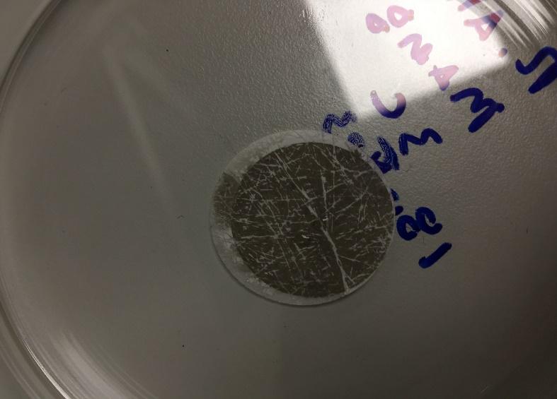
54 Aging of Fuels with Aged Oil, Metals and Water (MAM8) Brass A B C D Figure 32: Filters Post-treatment of Fuels Aged with Aged Oil, Brass, and Water (MAM8 1A-C) showing an unused filter (A), Aged B100 (B), Aged B10 (C), and Aged HVO (D) Copper A B C D Figure 33: Figure 32: Filters Post-treatment of Fuels Aged with Aged Oil, Copper, and Water (MAM8 2A-C) showing an unused filter (A), Aged B100 (B), Aged B10 (C), and Aged HVO (D) Iron A B C D Figure 34: Filters Post-treatment of Fuels Aged with Aged Oil, Iron, and Water (MAM8 3A-C) showing an unused filter (A), Aged B100 (B), Aged B10 (C), and Aged HVO (D) Aging of Fuels with Metals and Water (MAM9) Brass A B C D Figure 35: Filters Post-treatment of Fuels Aged with Brass, and Water (MAM9 1A-C) showing an unused filter (A), Aged B100 (B), Aged B10 (C), and Aged HVO (D) 47

, Aged")
 Iron A B C D Figure 37:")
 HVO (D) 48")

55 Copper A B C D Figure 36: Filters Post-treatment of Fuels Aged with Copper, and Water (MAM9 2A-C) showing an unused filter (A), Aged B100 (B), Aged B10 (C), and Aged HVO (D) Iron A B C D Figure 37: Filters Post-treatment of Fuels Aged with Iron, and Water (MAM9 3A-C) showing an unused filter (A), Aged B100 (B), Aged B10 (C), and Aged HVO (D) 48
This presentation focuses on Biodiesel, scientifically called FAME (Fatty Acid Methyl Ester); a fuel different in either perspective.
; a fuel different in either perspective.") Today, we know a huge variety of so-called alternative fuels which are usually regarded as biofuels, even though this is not always true. Alternative fuels can replace fossil fuels in existing combustion
Today, we know a huge variety of so-called alternative fuels which are usually regarded as biofuels, even though this is not always true. Alternative fuels can replace fossil fuels in existing combustion
Article: The Formation & Testing of Sludge in Bunker Fuels By Dr Sunil Kumar Laboratory Manager VPS Fujairah 15th January 2018
 Article: The Formation & Testing of Sludge in Bunker Fuels By Dr Sunil Kumar Laboratory Manager VPS Fujairah 15th January 2018 Introduction Sludge formation in bunker fuel is the source of major operational
Fuel Related Definitions
 Fuel Related Definitions ASH The solid residue left when combustible material is thoroughly burned or is oxidized by chemical means. The ash content of a fuel is the non combustible residue found in the
Biodiesel is NOT raw vegetable oil or SVO (Straight Vegetable Oil) or refined oil or filtered used cooking oil.
 or refined oil or filtered used cooking oil.") Biodiesel Update Biodiesel A fuel comprised of methyl/ethyl ester-based oxygenates of long chain fatty acids derived from the transesterification of vegetable oils, animal fats, and cooking oils. These
Biodiesel Update Biodiesel A fuel comprised of methyl/ethyl ester-based oxygenates of long chain fatty acids derived from the transesterification of vegetable oils, animal fats, and cooking oils. These
Biodistillate Fuels and Emissions in the U.S.
 Biodistillate Fuels and Emissions in the U.S. Presented to the Institute of Medicine Roundtable on Environmental Health Sciences, Research, and Medicine The Nexus of Biofuels, Energy, Climate Change, and
SYNERGISTIC EFFECTS OF ALCOHOL- BASED RENEWABLE FUELS: FUEL PROPERTIES AND EMISSIONS
 SYNERGISTIC EFFECTS OF ALCOHOL- BASED RENEWABLE FUELS: FUEL PROPERTIES AND EMISSIONS by EKARONG SUKJIT School of Mechanical Engineering 1 Presentation layout 1. Rationality 2. Research aim 3. Research
Production of Biodiesel from Used Groundnut Oil from Bosso Market, Minna, Niger State, Nigeria
 Production of Biodiesel from Used Groundnut Oil from Bosso Market, Minna, Niger State, Nigeria Alabadan B.A. Department of Agricultural and Bioresources Engineering, Federal University, Oye Ekiti. Ajayi
Oil & Gas. From exploration to distribution. Week 3 V19 Refining Processes (Part 1) Jean-Luc Monsavoir. W3V19 - Refining Processes1 p.
 Jean-Luc Monsavoir. W3V19 - Refining Processes1 p.") Oil & Gas From exploration to distribution Week 3 V19 Refining Processes (Part 1) Jean-Luc Monsavoir W3V19 - Refining Processes1 p. 1 Crude Oil Origins and Composition The objective of refining, petrochemical
Oil & Gas From exploration to distribution Week 3 V19 Refining Processes (Part 1) Jean-Luc Monsavoir W3V19 - Refining Processes1 p. 1 Crude Oil Origins and Composition The objective of refining, petrochemical
Renewable Diesel: The Sustainable High-Performance Fuel
 Renewable Diesel: The Sustainable High-Performance Fuel CONTENTS I. THE FUEL MADE FROM 100% RENEWABLE & SUSTAINABLE RAW MATERIALS II. IMPROVE OPERATIONS WHILE ALSO REDUCING YOUR ENVIRONMENTAL IMPACT III.
Impact of Biodiesel Fuel on Engine Parts
 Impact of Biodiesel Fuel on Engine Parts Presented by Prof. Dr.Liaquat Ali Memon Department of Mechanical Engineering, Quaid-e-Awam University of Engineering, Science & Technology, Nawabshah, Sindh, PAKISTAN
Author: Vincenzo Piemonte, Associate Professor, University UCBM Rome (Italy)
") Green Diesel Author: Vincenzo Piemonte, Associate Professor, University UCBM Rome (Italy) 1. Theme description Around 50% of the produced crude petroleum in the world is refined into transportation fuels
Green Diesel Author: Vincenzo Piemonte, Associate Professor, University UCBM Rome (Italy) 1. Theme description Around 50% of the produced crude petroleum in the world is refined into transportation fuels
Project Reference No.: 40S_B_MTECH_007
 PRODUCTION OF BIODIESEL FROM DAIRY WASH WATER SCUM THROUGH HETEROGENEOUS CATALYST AND PERFORMANCE EVALUATION OF TBC DIESEL ENGINE FOR DIFFERENT DIESEL AND METHANOL BLEND RATIOS Project Reference No.: 40S_B_MTECH_007
Alternative Automotive Fuels - Biodiesel
 Technical presentation to VW India Alternative Automotive Fuels - Biodiesel Fredrick A Bosch Ltd., Research & Development Date : 15 th July 2010 Venue : University of Agricultural Sciences, GKVK Campus,
Biodiesel Lifespan Quality Performance
 Biodiesel Lifespan Quality Performance AGQM e.v. Page 1 of 12 Biodiesel Lifespan Quality Performance Monitoring and Assessment Evaluation of Quality Changes in Biodiesel along the Logistics Chain Project
CONVERSION OF GLYCEROL TO GREEN METHANOL IN SUPERCRITICAL WATER
 CONVERSION OF GLYCEROL TO GREEN METHANOL IN SUPERCRITICAL WATER Maša Knez Hrnčič, Mojca Škerget, Ljiljana Ilić, Ţeljko Knez*, University of Maribor, Faculty of Chemistry and Chemical Engineering, Laboratory
INNOSPEC RESEARCH UPDATE. Nigel Broom 2017
 INNOSPEC RESEARCH UPDATE Nigel Broom 2017 May 2016. 12,Innospec, 2017 Inc. All Rights Reserved 1 FUTURE CHALLENGES FUEL March 2015 HYDRO-TREATMENT Composition Changes Aromatics / Olefins Diminished Solvency
What is Biodiesel? Biodiesel consists of alkyl-esters derived from a biological source
 Biodiesel What is Biodiesel? Biodiesel consists of alkyl-esters derived from a biological source Biodiesel can be used as a fuel in compression ignition engines (i.e. diesels) Can be blended with petroleum
Production and Properties of Biodistillate Transportation Fuels
 Production and Properties of Biodistillate Transportation Fuels AWMA International Specialty Conference: Leapfrogging Opportunities for Air Quality Improvement May 10-14, 2010 Xi an, Shaanxi Province,
Louis Dreyfus Claypool Holdings, LLC. Biodiesel Production Plant Claypool, Indiana
 Louis Dreyfus Claypool Holdings, LLC Biodiesel Production Plant Claypool, Indiana Soybeans 163,000 Bu. = 48 Railcars = 172 Trucks Electricity 156,695 Kwh Natural Gas 3,049 Dth Claypool Inputs/Outputs Per
Internal Combustion Engines
 Emissions & Air Pollution Lecture 3 1 Outline In this lecture we will discuss emission control strategies: Fuel modifications Engine technology Exhaust gas aftertreatment We will become particularly familiar
Module8:Engine Fuels and Their Effects on Emissions Lecture 36:Hydrocarbon Fuels and Quality Requirements FUELS AND EFFECTS ON ENGINE EMISSIONS
 FUELS AND EFFECTS ON ENGINE EMISSIONS The Lecture Contains: Transport Fuels and Quality Requirements Fuel Hydrocarbons and Other Components Paraffins Cycloparaffins Olefins Aromatics Alcohols and Ethers
Biodiesel Product Quality Challenges: Gaylord Palm Resort and Convention Center, Orlando Florida, February 4, Fuel Quality Services, Inc.
 Biodiesel Product Quality Challenges: Gaylord Palm Resort and Convention Center, Orlando Florida, February 4, 2008 Overview Introduction Product Quality Challenges Manufacturing Storage Conclusion. Biodiesel
The storage stability issue of Biodiesel and the additives solution. Long - Term Storage of Fuels Seminar Israeli Institute of Energy and Environment
 The storage stability issue of Biodiesel and the additives solution Long - Term Storage of Fuels Seminar Israeli Institute of Energy and Environment Tel Aviv, 3 of December 2008 An Introduction Biodiesel,
Biofuels from Regional Waste Sources. Advanced Energy Conference November 9, 2010 New York City
 Biofuels from Regional Waste Sources Advanced Energy onference November 9, 2010 New York ity Project Participants T. Butcher,. Brown, A. Vairavamurthy, G. Wei, and D. Mahajan: Brookhaven National Laboratory
V.Venkatakranthi Teja. N S Raju Institute of Technology (NSRIT), Sontyam, Visakhapatnam, Andhra Pradesh , India.
, Sontyam, Visakhapatnam, Andhra Pradesh , India.") Preparation of Waste Cooking Oil as Alternative Fuel and Experimental Investigation Using Bio-Diesel Setup a Comparative Study with Single Cylinder Diesel Engine Mr.S.Sanyasi Rao Pradesh - 531173, India.
Preparation of Waste Cooking Oil as Alternative Fuel and Experimental Investigation Using Bio-Diesel Setup a Comparative Study with Single Cylinder Diesel Engine Mr.S.Sanyasi Rao Pradesh - 531173, India.
PERP Program New Report Alert
 PERP Program New Report Alert January 2004 Nexant s hemsystems Process Evaluation/Research Planning program has published a new report, Biodiesel (02/03S2). Introduction The term biodiesel typically refers
Abstract Process Economics Program Report 251 BIODIESEL PRODUCTION (November 2004)
") Abstract Process Economics Program Report 251 BIODIESEL PRODUCTION (November 2004) Biodiesel is an ester of fatty acids produced from renewable resources such as virgin vegetable oil, animal fats and used
Abstract Process Economics Program Report 251 BIODIESEL PRODUCTION (November 2004) Biodiesel is an ester of fatty acids produced from renewable resources such as virgin vegetable oil, animal fats and used
Edexcel GCSE Chemistry. Topic 8: Fuels and Earth science. Fuels. Notes.
 Edexcel GCSE Chemistry Topic 8: Fuels and Earth science Fuels Notes 8.1 Recall that Hydrocarbons are compounds that contain carbon and hydrogen only 8.2 Describe crude oil as: A complex mixture of hydrocarbons
Biodiesel from Various Vegetable Oils as the Lubricity Additive for Ultra Low Sulphur Diesel (ULSD)
") AMM-5 The 2 st Conference of Mechanical Engineering Network of Thailand 7-9 October 27, Chonburi, Thailand Biodiesel from Various Vegetable Oils as the Lubricity Additive for Ultra Low Sulphur (ULSD) Subongkoj
AMM-5 The 2 st Conference of Mechanical Engineering Network of Thailand 7-9 October 27, Chonburi, Thailand Biodiesel from Various Vegetable Oils as the Lubricity Additive for Ultra Low Sulphur (ULSD) Subongkoj
Biodiesel Update. Eagle Core Team. Edward J. Lyford-Pike Advanced Engineering, Advanced Alternative Fuels group
 Biodiesel Update Eagle Core Team April 25 st, 2006 Edward J. Lyford-Pike Advanced Engineering, Advanced Alternative Fuels group BIODIESEL Outline Definition Fuel Characteristics Voice of the Customer Voice
Renewable Diesel & Biodiesel
 Renewable Diesel & Biodiesel Considerations for Sustainable Fleets Fueled By Convenience! REG can make it easier to manage all your fuel needs!!! REG-9000 biodiesel REG-9000/Renewable Diesel #2 ULSD Heating
Monitoring Biodiesel Fuel Quality
 Monitoring Biodiesel Fuel Quality National Biodiesel Conference User Track Fleet Implementation February 4, 2008 Randall von Wedel, Ph.D. BioSolar Group / CytoCulture RvWedel@gmail.com The (simplistic)
Neste MY Renewable Diesel. October 2017
 Neste MY Renewable Diesel October 2017 Safe Harbor Statement The following information contains, or may be deemed to contain, forward-looking statements. These statements relate to future events or our
Methanol recovery during transesterification of palm oil in a TiO2/Al2O3 membrane reactor: Experimental study and neural network modeling
 University of Malaya From the SelectedWorks of Abdul Aziz Abdul Raman 2010 Methanol recovery during transesterification of palm oil in a TiO2/Al2O3 membrane reactor: Experimental study and neural network
The Analysis of Biodiesel for Trace Metals and the Development of Certified Biodiesel Standards
 The Analysis of Biodiesel for Trace Metals and the Development of Certified Biodiesel Standards CRMMA Workshop Pittcon 2008 New Orleans, LA Author: Thomas Rettberg, Ph.D. VHG Labs, Inc. Manchester, NH
PRODUCT INFORMATION SHEET
 Page 1 of 18 31592 WYNN S DPF Cleaner & Regenerator WYNN S Diesel Particulate Filter Cleaner & Regenerator Product Number: 31592 12 x 325ml New technologies to reduce emissions with diesel engines The
BIODIESEL PRODUCTION BY A CONTINUOUS PROCESS USING A HETEROGENEOUS CATALYST
 J. Curr. Chem. Pharm. Sc.: 2(1), 2012, 12-16 ISSN 2277-2871 BIODIESEL PRODUCTION BY A CONTINUOUS PROCESS USING A HETEROGENEOUS CATALYST SHARDA D. NAGE *, K. S. KULKARNI, A. D. KULKARNI and NIRAJ S. TOPARE
Biodiesel Business Environment
 Biodiesel Business Environment By Patum Vegetable Oil co., ltd. February 12, 2008 Innovation on Biofuel in Thailand, Century Park Hotel Agenda Company Profile Biodiesel Technology Country Policy & Regulation
Standard Test Method for Sulfur in the Analysis Sample of Coal and Coke Using High-Temperature Tube Furnace Combustion
 IAS Accreditation Number Company Name Address Contact Name Telephone +966-14-398-2118 Effective Date of Scope May 1, 2018 Accreditation Standard ISO/IEC 17025:2017 TL-743 Yanbu Industrial Area Yanbu, Madina
ASTM D Standard Specification for Biodiesel Fuel (B 100) Blend Stock for Distillate Fuels
 Blend Stock for Distillate Fuels") ASTM D 6751 02 Standard Specification for Biodiesel Fuel (B 100) Blend Stock for Distillate Fuels Summary This module describes the key elements in ASTM Specifications and Standard Test Methods ASTM Specification
ASTM D 6751 02 Standard Specification for Biodiesel Fuel (B 100) Blend Stock for Distillate Fuels Summary This module describes the key elements in ASTM Specifications and Standard Test Methods ASTM Specification
Distillation. How you can benefit from the future of biodiesel
 Distillation How you can benefit from the future of biodiesel The next frontier in biodiesel. The future of biodiesel production is actually rooted in a process that has been known for centuries. Scholars
Background on Biodiesel
 Background on Biodiesel Jon Van Gerpen Dept. of Biological and Agricultural Engineering University of Idaho Moscow, ID 83844 (208) 885-7891 jonvg@uidaho.edu Sustainable Transportation on Campus September
The Purification Feasibilityof GlycerinProduced During
 The Purification Feasibilityof GlycerinProduced During BiodieselProduction S. Soulayman, F. Mustafa, and A. Hadbah Higher Institute for Applied Sciences and technology, Damascus, P.O. Box 31983, Syria,
Cleaner liquid fuels and improved vehicular technologies
 Cleaner liquid fuels and improved vehicular technologies Dr. Arun Jaura VP Technology & Head of EIEC 2011 Eaton Corporation. All rights reserved. 1 1 Cleaner Liquid Fuels The growing demand for clean fuels
Biodiesel Fuel Quality
 2012 Collective Biofuels Conference Temecula, California Biodiesel Fuel Quality August 17-19, 2012 Presented by Gorge Analytical, LLC Significant effort and technical consideration has gone in to developing
Biodiesel and SmartWay Grow and Go Go. EPA-MMTA Fuel-Saving Seminar June 15, 2007
 Biodiesel and SmartWay Grow and Go Go EPA-MMTA Fuel-Saving Seminar June 15, 2007 SmartWay Grow and Go Focus: Biodiesel and E85 Goal: By 2012, 25% of SmartWay Partners commit to use renewable fuels; by
ATTENTION: DIESEL FUEL USERS
 P a g e 2 ATTENTION: DIESEL FUEL USERS Have you noticed Smelly fuel? Water in your fuel? Diesel bug? Algae/bacteria? Slime in fuel tanks? Excessive black smoke? Nature itself adds to the problems of the
HERCULES-2 Project. Deliverable: D8.8
 HERCULES-2 Project Fuel Flexible, Near Zero Emissions, Adaptive Performance Marine Engine Deliverable: D8.8 Study an alternative urea decomposition and mixer / SCR configuration and / or study in extended
Automotive Technology
 International Conference on Automotive Technology An Experimental Study on the Performance and Emission Characteristics of a Single Cylinder Diesel Engine Using CME- Diesel Blends. Hari Vasudevan a*,sandip
Onboard Plasmatron Generation of Hydrogen Rich Gas for Diesel Engine Exhaust Aftertreatment and Other Applications.
 PSFC/JA-02-30 Onboard Plasmatron Generation of Hydrogen Rich Gas for Diesel Engine Exhaust Aftertreatment and Other Applications L. Bromberg 1, D.R. Cohn 1, J. Heywood 2, A. Rabinovich 1 December 11, 2002
2
 1 2 3 4 5 6 7 8 9 Arguments Against The Use Of FAME Biodiesel In Modern Diesel Engines Rich Cregar Fellow, Institute for Emerging Issues, NCSU White House Champion of Change APWA Fueling the Conversation
Effects Of Free Fatty Acids, Water Content And Co- Solvent On Biodiesel Production By Supercritical Methanol Reaction
 Effects Of Free Fatty Acids, Water Content And Co- Solvent On Biodiesel Production By Supercritical Methanol Reaction Kok Tat Tan*, Keat Teong Lee, Abdul Rahman Mohamed School of Chemical Engineering,
Biodiesel Analytics. Important Parameters and their Meaning
 Important Parameters and their Meaning Content of fatty acid methyl esters ( ester content ) Test method: EN 14103 (GC) Limit value: min. 96.5% (m/m) The content of fatty acid methyl esters, frequently
PERFORMANCE AND EMISSION ANALYSIS OF DIESEL ENGINE BY INJECTING DIETHYL ETHER WITH AND WITHOUT EGR USING DPF
 PERFORMANCE AND EMISSION ANALYSIS OF DIESEL ENGINE BY INJECTING DIETHYL ETHER WITH AND WITHOUT EGR USING DPF PROJECT REFERENCE NO. : 37S1036 COLLEGE BRANCH GUIDES : KS INSTITUTE OF TECHNOLOGY, BANGALORE
CHAPTER 2 LITERATURE REVIEW AND SCOPE OF THE PRESENT STUDY
 57 CHAPTER 2 LITERATURE REVIEW AND SCOPE OF THE PRESENT STUDY 2.1 LITERATURE REVIEW Biodiesel have been processed from various plant derived oil sources including both Edible and Non-Edible oils. But,
Irish Biodiesel Production and Market Outlook
 Irish Biodiesel Production and Market Outlook Mossie O Donovan Commercial Director EcoOla Ltd Thursday, 18 February 2010 The Tipperary Institute, Thurles 1 Overview o Motivation o Biodiesel Production
Quantitative Analysis of Chemical Compositions from Various Sources of Crude Glycerine
 CMU.J.Nat.Sci.Special Issue on Agricultural & Natural Resources (2012) Vol.11 (1) 157 Quantitative Analysis of Chemical Compositions from Various Sources of Crude Glycerine Adisorn Settapong * and Chaiyawan
Biofuels and characteristics
 Lecture-16 Biofuels and characteristics Biofuels and Ethanol Biofuels are transportation fuels like ethanol and biodiesel that are made from biomass materials. These fuels are usually blended with petroleum
Part No oz. (946 ml) bottle 11 oz. (325 ml) can
 bottle 11 oz. (325 ml) can") Diesel Service Page 1 / Page 2 The BG Diesel Service addresses the needs of these specialized powerplants by restoring lost performance and preventing costly repairs. This service will reduce overall maintenance
Diesel Service Page 1 / Page 2 The BG Diesel Service addresses the needs of these specialized powerplants by restoring lost performance and preventing costly repairs. This service will reduce overall maintenance
On-Line Process Analyzers: Potential Uses and Applications
 On-Line Process Analyzers: Potential Uses and Applications INTRODUCTION The purpose of this report is to provide ideas for application of Precision Scientific process analyzers in petroleum refineries.
Standard Specification for Biodiesel Fuel Blend Stock (B100) for Middle Distillate Fuels 1
 for Middle Distillate Fuels 1") Designation: D 6751 03a An American National Standard Standard Specification for Biodiesel Fuel Blend Stock (B100) for Middle Distillate Fuels 1 This standard is issued under the fixed designation D 6751;
Designation: D 6751 03a An American National Standard Standard Specification for Biodiesel Fuel Blend Stock (B100) for Middle Distillate Fuels 1 This standard is issued under the fixed designation D 6751;
What s s in your Tank?
 What s s in your Tank? Biodiesel Could Be The Answer! Matthew Brown Lakewood High School Tom Hersh Golden West Community College Overview What is biodiesel? Chemistry of biodiesel Safety Making Biodiesel
Hydrocarbons 1 of 29 Boardworks Ltd 2016
 Hydrocarbons 1 of 29 Boardworks Ltd 2016 Hydrocarbons 2 of 29 Boardworks Ltd 2016 What are hydrocarbons? 3 of 29 Boardworks Ltd 2016 Some compounds only contain the elements carbon and hydrogen. They are
Methanol distribution in amine systems and its impact on plant performance Abstract: Methanol in gas treating Methanol impact on downstream units
 Abstract: Presented at the AIChE Spring 2015 meeting in Austin, TX, USA Methanol distribution in amine systems and its impact on plant performance Anand Govindarajan*, Nathan A. Hatcher, and Ralph H. Weiland
DAVI DOS SANTOS, STEPHEN MONTGOMERY, ANN NUNNELLEY, MD NURUDDIN BSEN 5540/6540: BIOMASS AND BIOFUELS BIODIESEL PRODUCTION FROM VEGETABLE OIL GROUP:
 DAVI DOS SANTOS, STEPHEN MONTGOMERY, ANN NUNNELLEY, MD NURUDDIN BSEN 5540/6540: BIOMASS AND BIOFUELS BIODIESEL PRODUCTION FROM VEGETABLE OIL GROUP: POPLAR 13 NOVEMBER, 2015 Table of Contents Introduction
EXPERIMENTAL INVESTIGATION OF THE EFFECT OF HYDROGEN BLENDING ON THE CONCENTRATION OF POLLUTANTS EMITTED FROM A FOUR STROKE DIESEL ENGINE
 EXPERIMENTAL INVESTIGATION OF THE EFFECT OF HYDROGEN BLENDING ON THE CONCENTRATION OF POLLUTANTS EMITTED FROM A FOUR STROKE DIESEL ENGINE Haroun A. K. Shahad hakshahad@yahoo.com Department of mechanical
The Importance of Biodiesel Meeting the ASTM D6751 Standard. Barbara E Goodrich Manager, Engine Fluids John Deere Power Systems 6 February 2008
 The Importance of Biodiesel Meeting the ASTM D6751 Standard An OEM Perspective on Fuel Quality Barbara E Goodrich Manager, Engine Fluids John Deere Power Systems 6 February 2008 Overview Outline ASTM D6751
Study on crystallization mechanism of saturated fatty acid methyl ester in biodiesel
 Study on crystallization mechanism of saturated fatty acid methyl ester in biodiesel Yongbin Lai 1, a, Guang Wu 1, Xiu Chen 2, Xiaoling Chen 2, Li Kong 2 and Lei Zhong 2 1 School of Mechanical Engineering,
Power Performance and Exhaust Gas Analyses of Palm Oil and Used Cooking Oil Methyl Ester as Fuel for Diesel Engine
 ICCBT28 Power Performance and Exhaust Gas Analyses of Palm Oil and Used Cooking Oil Methyl Ester as Fuel for Diesel Engine R. Adnan *, Universiti Tenaga Nasional, MALAYSIA I. M. Azree, Universiti Tenaga
SYNTHESIS OF BIODIESEL
 SYNTHESIS OF BIODIESEL AIM 1. To generate laboratory know-how for the process of production of biodiesel from the given oil feed stock 2. To perform basic mass and energy balance calculations for a large
Experimental Investigations on a Four Stoke Diesel Engine Operated by Jatropha Bio Diesel and its Blends with Diesel
 International Journal of Manufacturing and Mechanical Engineering Volume 1, Number 1 (2015), pp. 25-31 International Research Publication House http://www.irphouse.com Experimental Investigations on a
Experimental investigation on constant-speed diesel engine fueled with. biofuel mixtures under the effect of fuel injection
 Experimental investigation on constant-speed diesel engine fueled with biofuel mixtures under the effect of fuel injection 1 I. Vinoth kanna *, 2 K. Subramani, 3 A. Devaraj 1 2 3 Department of Mechanical
Technology Development within Alternative Fuels. Yves Scharff
 Technology Development within Alternative Fuels Yves Scharff 1 Agenda Introduction Axens and Alternative Fuels Axens Renewable Iso-paraffins Route 2 Why Alternative Fuels? Environmental Regulation By 2020,
Biodiesel Production and Analysis
 Biodiesel Production and Analysis Introduction A key current focus in science and engineering is the development of technologies for generating and utilizing new sources of energy. Climate change, geopolitics,
Q1. The table shows how much carbon dioxide is produced when you transfer the same amount of energy by burning coal, gas and oil.
 Q1. The table shows how much carbon dioxide is produced when you transfer the same amount of energy by burning coal, gas and oil. (a) (b) Use the information from the table to complete the bar-chart. The
FUEL QUALITY HAS DECLINED
 FUEL QUALITY HAS DECLINED Fuel Quality has Deteriorated because... Over the last two decades, the cetane number and the API gravity, the basic measures of crude oil quality have declined Diesel fuel quality
Gaseous fuel, production of H 2. Diesel fuel, furnace fuel, cracking
 ALKANES Introduction Hydrocarbons, as the name implies are compounds whose molecules contain only carbon and hydrogen. They are extracted from petroleum, natural gas and coal. Straight chain alkanes take
General Guide of Lubricants Recycle
 General Guide of Lubricants Recycle This paper is a disscution on waste/used lubricating oil recycling. For Equipment & Solution Enquiry: solution@wpenvironmental.com For More Information: www.wpenvironmental.com
Study of viscosity - temperature characteristics of rapeseed oil biodiesel and its blends
 Study of viscosity - temperature characteristics of rapeseed oil biodiesel and its blends Li Kong 1, Xiu Chen 1, a, Xiaoling Chen 1, Lei Zhong 1, Yongbin Lai 2 and Guang Wu 2 1 School of Chemical Engineering,
Biodiesel Specification in Indonesia
 Biodiesel Specification in Indonesia Tatang H Soerawidjaja President of Indonesian Association of Bioenergiy Scientists and Technologists (IABEST), Member of Indonesian Academiy of Science (AIPI), Member
PERFORMANCE AND EMISSION CHARACTERISTICS OF DIESEL ENGINE USING RICE BRAN OIL METHYL ESTER BLEND WITH ADITIVE DIETHYL ETHER (DEE)
") International Journal of Science, Engineering and Technology Research (IJSETR), Volume 3, Issue 2, February 214 PERFORMANCE AND EMISSION CHARACTERISTICS OF DIESEL ENGINE USING RICE BRAN OIL METHYL ESTER
International Journal of Science, Engineering and Technology Research (IJSETR), Volume 3, Issue 2, February 214 PERFORMANCE AND EMISSION CHARACTERISTICS OF DIESEL ENGINE USING RICE BRAN OIL METHYL ESTER
Softening point by Ring & Ball. Density and relative density of liquids by Hubbart pycnometer
 Softening point by Ring & Ball Density and relative density of liquids by Hubbart pycnometer Distillation of petroleum Melting point of petroleum wax Precipitation number of lubricating oils Saponification
Leading the World in Emissions Solutions
 Leading the World in Emissions Solutions Solutions for Vehicle Emissions CDTI is a leading global manufacturer and distributor of heavy duty diesel and light duty vehicle emissions control systems and
The Need for Alternative Fuel Sources: Biodiesel and Other Options. Jill Burrows 11/21/05
 The Need for Alternative Fuel Sources: Biodiesel and Other Options Jill Burrows 11/21/05 Diesel Engines 94% of all goods in the Unites States are transported by vehicles with diesel powered engines Used
Influence of power to liquid fuels on the emissions of modern passenger cars
 Influence of power to liquid fuels on the emissions of modern passenger cars T. Garbe, M. Hönig, W. Kaszás, J. Klose, H. Bröker, E. Pott Volkswagen AG Motivation for e-fuels climate protection CO 2 -neutral
A Winning Combination: REG Ultra Clean Diesel
 A Winning Combination: REG Ultra Clean Diesel Benefits of the Newest Renewable Blend The latest innovation in renewable fuel is REG Ultra Clean Diesel. The product is a blend of two leading diesel replacements:
ANNEX 2, REFERENCE FUELS
 ANNEX 2, REFERENCE FUELS A.2.1. A.2.1.1. EUROPE, INDIA, SOUTH AFRICA Petrol (E5) Parameter Unit Limits (1) Test method Research octane number, RON 95.0 EN 25164 pren ISO 5164 Motor octane number, MON 85.0
The preparation of biodiesel from rape seed oil or other suitable vegetable oils
 The preparation of biodiesel from rape seed oil or other suitable vegetable oils Method Note This method produces biodiesel relatively quickly, though the product is not pure enough to burn in an engine.
Refinery and Petrochemicals technology innovations are aimed to
 Innovation Downstream Innovation Refinery and Petrochemicals technology innovations are aimed to maximize efficiency; minimize utilities consumption; improve the environmental quality or finished products;
Oxidation Technologies for Stationary Rich and Lean Burn Engines
 Oxidation Technologies for Stationary Rich and Lean Burn Engines ICAC MARAMA Advances in Air Pollution Control Technologies May 18-19, 2011 Baltimore, MD 1 Overview Oxidation catalyst technologies Oxidation
Tier 4 Bobcat Engine. Andrew Johnson Product Service Manager, Bobcat Company Rocky Mountain Asphalt Conference and Equipment Show Feb.
 Tier 4 Bobcat Engine Andrew Johnson Product Service Manager, Bobcat Company Rocky Mountain Asphalt Conference and Equipment Show Feb. 21 st 2018 Overview Tier 4 Diesel Engine Technologies Bobcat s Tier
AFRICAN REFINERS ASSOCIATION BIOFUELS CONFERENCE th June 2012 ARA Biofuels Conference Luanda
 AFRICAN REFINERS ASSOCIATION BIOFUELS CONFERENCE 2012 1 What are biofuels? Biofuels are a biodegradable energy source produced from renewable sources Any fuel with a minimum of 80% content by volume of
No reason to wait: Start the transition to renewable fuels now!
 PRESS info P07908EN / Per-Erik Nordström 5 September 2007 No reason to wait: Start the transition to renewable fuels now! Scania maintains its position that the transition to renewable fuels can and should
PERFORMANCE AND EMISSION TEST OF CANOLA AND NEEM BIO-OIL BLEND WITH DIESEL
 PERFORMANCE AND EMISSION TEST OF CANOLA AND NEEM BIO-OIL BLEND WITH DIESEL MR.N.BALASUBRAMANI 1, M.THANASEGAR 2, R.SRIDHAR RAJ 2, K.PRASANTH 2, A.RAJESH KUMAR 2. 1Asst. Professor, Dept. of Mechanical Engineering,
Proposal to Determine Various Properties of Biodiesel Fuels Based on Methyl Ester. Composition. Jason Freischlag. Dr. Porter Chem /25/2013
 1 Proposal to Determine Various Properties of Biodiesel Fuels Based on Methyl Ester Composition Jason Freischlag Dr. Porter Chem 402 11/25/2013 2 Specific Aims Biodiesel is an alternative fuel source that
Biodiesel Production and Analysis
 Biodiesel Production and Analysis Introduction A key current focus in science and engineering is the development of technologies for generating and utilizing new sources of energy. Climate change, geopolitics,
M1.(a) C 6 H [5] Page 2. PhysicsAndMathsTutor.com
![M1.(a) C 6 H [5] Page 2. PhysicsAndMathsTutor.com](/thumbs/96/127099908.jpg "M1.(a) C 6 H [5] Page 2. PhysicsAndMathsTutor.com") M.(a) C 6 H 4 (b) A (c) B (d) C (e) Propanol [5] Page 2 M2.(a) more than one line from test negates the mark (b) (i) place a lighted splint at the mouth of the tube there is a squeaky pop dependent on
M.(a) C 6 H 4 (b) A (c) B (d) C (e) Propanol [5] Page 2 M2.(a) more than one line from test negates the mark (b) (i) place a lighted splint at the mouth of the tube there is a squeaky pop dependent on
8/3/2012 SIF: Energy School 2012,Varenna. Omar Said
 Omar Said Introduction to myself Name: Omar Said (I am in Petroleum and Petrochemicals Engineering senior student Cairo University). Experience : Schlumberger oil service company trainee (wire line segment).
SCOPE OF ACCREDITATION TO ISO/IEC 17043:2010. ASTM INTERNATIONAL 100 Barr Harbor Drive West Conshohocken, PA Amy Meacock
 SCOPE OF ACCREDITATION TO ISO/IEC 17043:2010 ASTM INTERNATIONAL 100 Barr Harbor Drive West Conshohocken, PA 19428 Amy Meacock 610 832 9688 PROFICIENCY TESTING PROVIDER Valid To: May 31, 2021 Certificate
TULSION BIODIESEL PRODUCTION: WET VS. DRY WHICH METHOD SHOULD YOU USE?
 TULSION BIODIESEL PRODUCTION: WET VS. DRY WHICH METHOD SHOULD YOU USE? T-45 BD & T-45 BD Macro Background: Biodiesel fuel, a proven alternative to petroleum diesel, is commonly made via a transesterification