Auxiliary Air Suspension. Installation Manual L.AL.02. AL-KO Chassis June 2009
|
|
|
- Griselda Jones
- 5 years ago
- Views:
Transcription


1 Auxiliary Air Suspension Installation Manual AL-KO Chassis June 2009
2 CONTENTS 1. FOREWORD VERY IMPORTANT PREREQUISITES INTRODUCTION VERY IMPORTANT NOTES CONTENTS OF THE AIR SUSPENSION KIT INSTRUCTIONS FOR INSTALLATION Installing the Lower Brackets Installing the Upper Brackets Installing the Air Springs Fitting of Inflator Console Tube Connection and Disconnection, Cutting and Routing Brake Adjustment Spring Inflation Maintenance INSTALLATION DIAGRAMS EPILOGUE Dunlop Systems and Components Het Wegdam CA Hengevelde Nederland Tel. +31 (0) Fax. +31 (0) Dunlop Systems and Components Holbrook Lane Coventry CV6 4QX United Kingdom Tel. +44 (0) Fax. +44 (0) , Dunlop Systems and Components 2
3 1. FOREWORD This manual provides instructions for the installation of an auxiliary air suspension kit, developed specifically for Motorhomes with an AL-KO torsion axle ( ). To ensure correct installation of the kit, it is strongly recommended that these instructions are read thoroughly before commencing any installation work. Installation should only be carried out by a suitably qualified mechanic or specialist installation facility. Dunlop Systems and Components will not accept any responsibility for faults or defects arising from incorrect installation, which automatically renders the guarantee invalid. IMPORTANT : Manufacturer s Declaration Form A manufacturer s declaration form is provided with your kit. Following installation of the kit please ensure that this form is completed, signed by a qualified fitter and a copy is returned to Dunlop Systems and Components by post, fax or . Part Number: Auxiliary Air Suspension for Al-Ko chassis 3
4 2. VERY IMPORTANT PREREQUISITES Check the condition of the Torsion Axle of your Vehicle Before attempting to fit an auxiliary air suspension system to your vehicle, it is extremely important to be aware that the torsion axle of your vehicle must be in good condition. Please observe all of the following guidelines Never install assist (air) springs if there is any indication of faults within the axle assembly AL-Ko recommends a revision of the axle every 100, ,000 km (62,000 75,000 miles) Air springs serve only to assist the torsion springs Observe whether the vehicle is listing significantly to one side, which would indicate a damaged or broken torsion spring Lift the rear of the vehicle until the lever arm rests against the bump stop and observe that the lever arm moves smoothly during lifting, so indicating adequate lubrication listen in the area near to the lever during lifting, since noise may indicate a broken torsion spring. If in doubt, repeat the lift using some means of improving audibility (ideally a stethoscope if available, or alternatively a screwdriver or length of bar touching the lever at one end and an ear at the other lift a road wheel by hand and observe the lever arm in its housing for backlash. This should not exceed approximately 0.5mm. The axle has three splined torsion bars. Be aware that if the fixing points of these bars are broken then the lever arm may dismount from its housing with the vehicle in motion! Try to find out whether any galling has taken place at the bearings Remove grease nipples and check the quality of the grease (make a point of greasing the nipples as a matter of course) 4
5 3. INTRODUCTION Thank you for choosing an auxiliary air suspension kit from the range offered by Dunlop Systems and Components. Auxiliary air suspension is fitted in tandem with the standard steel springs of the vehicle suspension, and provides enhancements in terms of both the stability of the vehicle and the comfort of the passengers Vehicle Levelling Simply by varying the air pressure in the springs, the vehicle can be levelled both front-to-rear and side-to-side. Keeping the vehicle level optimises stability, ensures correct headlamp beam distribution and reduces tyre wear arising from uneven distribution of weight. Straight Line Stability Straight line stability is greatly increased at higher speeds, and when subjected to buffeting from cross-winds or large overtaking vehicles Reduced Body Roll Body roll when cornering or negotiating roundabouts is significantly reduced. Fatigue Reduction and Wear Compensation Suspension fatigue is reduced, so helping to prevent leaf springs from sagging under repeated or constant loading. Any sagging already present can be compensated-for. This is a particular benefit for motorhomes, which are always fully laden. Ride Comfort Air springs help to absorb shock loads from uneven road surfaces, therefore general ride quality is much improved. 4. VERY IMPORTANT NOTES Gross Vehicle Weight (GVW) Air assist kits are not in themselves designed to increase the gross vehicle weight (GVW) rating of a vehicle. They do not legally allow for carriage of a load greater than the carrying capacity stated on the data plate of the vehicle. Do not exceed the maximum load specified by the vehicle manufacturer to avoid compromising passenger safety to prevent possible damage to the vehicle for legal reasons 5
6 Vehicle Uprating Despite the above words of caution, it is possible to upgrade the weight rating of your vehicle. This must be carried-out by a specialist supplier that will carry out any necessary modifications in addition to fitting the air assist kit complete documentation as necessary to inform the Vehicle and Operator Services Agency (VOSA) a mandatory requirement supply and fit a new weight plate to replace the original plate supplied with the vehicle This process applies to United Kingdom registered vehicles. The process in other countries may be different. 6

7 5. CONTENTS OF THE AIR SUSPENSION KIT Item # Part Number Description Quantity Upper bracket left side Upper bracket right side Lower plate left and right side 1 4 OP.LB.CO.SZ5520 Air Spring 2 Other Parts, not on the Assembly Diagram as above Bolts and nuts, as required Blue and black air tubing Tie wraps Schrader valves Declaration of conformity Installation manual 7

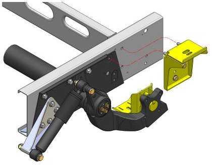
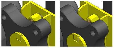
8 6. INSTRUCTIONS FOR INSTALLATION Preparation and Precaution Before beginning installation, ensure that you have sufficient clearance between the axle and the chassis. Use a jack if necessary. Install at one side of the vehicle at a time. Pay attention to your safety at all times during installation - always use axle stands to support the vehicle! The following instructions make reference to the diagrams on pages 14 to 18 inclusive Installing the Lower Brackets 1. Lift the rear of the vehicle until there is no tension in the springs Figures 1 and 2 2. Insert the key into the centre hole of the suspension arm Figures 3 and 4 3. Push the lower plate into the large hole in the suspension arm until the ribs are in contact with the arm Figures 5 and 6 4. Insert a M12 x 25 bolt with washer and spring washer into the keyway. Do not tighten fully so that alignment is possible at a later stage Figures 7 and Installing the Upper Brackets 1. Remove the clamping strap from the brake hose then lift the hose from its fixing bracket. Now remove the fixing bracket from the chassis Figures 9 and Remove the four bolts as shown in figures 13 and Prepare the upper bracket for installation by inserting four bolts through the holes in both the bracket and the spacer plate Figures 11 and Attach the upper bracket to the chassis Figures 15 and Attach the brake line to the upper bracket via the clamp Figure 26 8
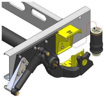
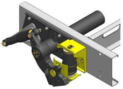
9 6.3. Installing the Air Springs 1. Connect the air tubes to the air springs, using black for the left side and blue for the right side. Guide the tube through its designated hole in the upper bracket (the one closest to the chassis) - Figures 17 and Attach the air spring top plate to the upper bracket using a single M10 x 20 bolt with washer and locking ring Figures 19 and 20. Do not tighten the bolt as yet. 3. Lower the vehicle to the desired ride height Figure Carefully inflate the air spring a little until the piston is in contact with the lower bracket 5. Attach the piston to the bottom bracket using a single M12 x 25 bolt with washer and locking ring. Once again, do not tighten the bolt as yet. 6. Inflate the spring to a pressure of approximately 1 bar (14.5psi). Align the spring and then tighten the bolt at both the top and the bottom. 7. Check the position of the bottom bracket and align as necessary 8. Once all alignments are complete, tighten the keyway bolt Figures 24 and 25 9

.")
")


10 6.4. Fitting of Inflator Console Standard Option 1 Option 2 Special Dashboard Panel for Fiat Ducato X244 Your kit is supplied either with the standard inflator console having two valves only (above, top-left), or an optional console having both valves and pressure gauges (Option 1 or Option 2 above). Mount the console in a position of your choice whereby it is firmly fixed, has some protection from the environment (particularly important for a console with gauges) and is easily accessible. Suggested possible locations include... Console with Valves Only on the rear bumper at the rear beside the license plate on the chassis next to a rear wheel in a service shutter beside the fuel cap Console with Valves and Gauges in the vehicle cabin, within reach and sight of the driver in the wall of a cupboard (motorhomes) in a service shutter 10


11 6.5. Tube Connection and Disconnection, Cutting and Routing Connection and Disconnection Tubes are connected as shown by the diagrams below... A B C A. Slide a nut over the end of the tube B. Push the tube onto the connector as far as possible C. Feed the nut up to the connector, fully tighten by hand and finally tighten one additional turn using spanners Cutting To achieve good sealing and air-tight fitting of tube ends to their connecting parts, it is very important to cut tubing cleanly and squarely. A dedicated guillotine action tubing cutter is recommended, or a craft knife if such a tool is not available. Do not use electrician s side cutters. A dedicated tubing cutter - Recommended Electrician s Side Cutters NOT Recommended Routing Study the underside of the vehicle and decide how to route each branch of the air circuit To minimise the risk of chafing, avoid running tubing over metal edges as much as possible Avoid close proximity to heat sources such as the exhaust assembly Choose a route that provides as much protection as possible from dirt, debris and any solid objects that may impact the underside of the vehicle It is recommended that tubes are guided alongside brake lines as much as possible. 11
12 6.6. Brake Adjustment As your vehicle is fitted with an antilock braking system, there is no need for any adjustment following fitment of your air assist kit Spring Inflation Once installation of the air assist kit is complete, inflate the springs via the inflator console taking careful note of the following... Maximum and Minimum Pressure Maximum Pressure 7.0bar Minimum Pressure 0.5bar Do not exceed 7.0bar (101psi), which is the recommended maximum charge pressure for the air springs. The springs may be deflated if the vehicle is to be stored for a lengthy period without use, but a pressure of at least 0.5bar (7.25psi) should be maintained at all times in order to avoid possible compression damage to the springs Maintenance Following installation, it is recommended that all metal parts are coated with a protective substance such as body wax. The system does not require very much maintenance other than to maintain air pressure in the springs. Much like a tyre, the system may lose a little air over time. to keep the air bellows clean. It is suggested that, when washing the vehicle, the bellows are inspected and cleaned as necessary (preferable by spraying). Look in particular for stones or grit trapped between convolutes, as this may damage the bellow. 12
13 7. INSTALLATION DIAGRAMS 13
14


15

16
17
18 8. EPILOGUE Dunlop Systems and Components hopes that you enjoy the benefits that your air suspension system will provide for you. To ensure optimal performance, we advise that you have your system checked frequently by qualified personnel. As recommended in the fitting instructions, it is important to coat all the steel parts with a protective substance such as body wax. IMPORTANT : Manufacturer s Declaration Form A manufacturer s declaration form is provided with your kit. Following installation of the kit please ensure that this form is completed, signed by a qualified fitter and a copy is returned to Dunlop Systems and Components by fax, post or . As a condition of your warranty, modifications to the system may only be carried out by personnel of Dunlop Systems and Components. Enquiries For general enquiries please either telephone Dunlop Systems and Components Nederland : +31 (0) Dunlop Systems and Components UK : +44 (0) or info@dunlopsystems.com. 18
547 33 30 68 Dunlop Systems and Components Holbrook Lane Coventry CV6 4QX United Kingdom Tel. +44 (0)24 7629 3300 Fax.")
19 Auxiliary Air Suspension Dunlop Systems and Components Het Wegdam CA Hengevelde Nederland Tel. +31 (0) Fax. +31 (0) Dunlop Systems and Components Holbrook Lane Coventry CV6 4QX United Kingdom Tel. +44 (0) Fax. +44 (0)
AIR-SUSPENSION. Designed for: Alko Chassis
 AIR-SUSPENSION Dunlop Systems and Components Het Wegdam 22 7496 CA Hengevelde The Netherlands Tel.: +31-(0)547-333065 Fax: +31-(0)547-333068 Website: www.dunlopsystems.com Art. nr.: L.AL.02 Designed for:
Auxiliary Air Suspension. Installation Manual L.NAV.05.C.M. Nissan Navara (D40) May 2009
 May 2009") Auxiliary Air Suspension Installation Manual (D40) May 2009 CONTENTS 1. FOREWORD...3 2. INTRODUCTION...4 3. VERY IMPORTANT NOTES...5 4. COMPLETE ASSEMBLY...7 5. INSTRUCTIONS FOR INSTALLATION...8 5.1. Installation
Auxiliary Air Suspension Installation Manual (D40) May 2009 CONTENTS 1. FOREWORD...3 2. INTRODUCTION...4 3. VERY IMPORTANT NOTES...5 4. COMPLETE ASSEMBLY...7 5. INSTRUCTIONS FOR INSTALLATION...8 5.1. Installation
L.312.C.M. Auxiliary Air Suspension. Installation Manual. Mercedes Benz Sprinter 200/300 Series ( ) Volkswagen LT ( )
 Volkswagen LT ( )") Auxiliary Air Suspension Installation Manual Mercedes Benz Sprinter 200/300 Series (1995 2006) Volkswagen LT 28-35 (1995 2006) November 2008 CONTENTS 1. FOREWORD...3 2. INTRODUCTION...4 3. VERY IMPORTANT
Auxiliary Air Suspension Installation Manual Mercedes Benz Sprinter 200/300 Series (1995 2006) Volkswagen LT 28-35 (1995 2006) November 2008 CONTENTS 1. FOREWORD...3 2. INTRODUCTION...4 3. VERY IMPORTANT
Auxiliary Air Suspension. Installation Manual L.HI.L4.C.M. Toyota Hilux 4 WD. May 2011
 Auxiliary Air Suspension Installation Manual Toyota Hilux 4 WD May 2011 CONTENTS 1. FOREWORD... 3 2. INTRODUCTION... 4 3. VERY IMPORTANT NOTES... 5 4. COMPLETE ASSEMBLY... 7 5. INSTRUCTIONS FOR INSTALLATION...
L.D84.C.M. Auxiliary Air Suspension. Installation Manual
 Auxiliary Air Suspension Installation Manual Citroën Jumper / Relay X280/X290 (1984 1993) Fiat Ducato X280/X290 (1984 1993) Peugeot Boxer X280/X290 (1984 1993) November 2008 CONTENTS 1. FOREWORD... 3 2.
L.D02.C.M(.A) Installation Manual. Citroën Jumper X244, Fiat Ducato X244, Peugeot Boxer X244, Auxiliary Air Suspension
 Installation Manual. Citroën Jumper X244, Fiat Ducato X244, Peugeot Boxer X244, Auxiliary Air Suspension") Auxiliary Air Suspension Installation Manual L.D02.C.M(.A) Citroën Jumper X244, 2002 2006 Fiat Ducato X244, 2002 2006 Peugeot Boxer X244, 2002 2006 December 2008 CONTENTS 1. FOREWORD... 3 2. INTRODUCTION...
Auxiliary Air Suspension Installation Manual L.D02.C.M(.A) Citroën Jumper X244, 2002 2006 Fiat Ducato X244, 2002 2006 Peugeot Boxer X244, 2002 2006 December 2008 CONTENTS 1. FOREWORD... 3 2. INTRODUCTION...
L.D94.C.M(.A) Auxiliary Air Suspension. Installation Manual
 Auxiliary Air Suspension. Installation Manual") Auxiliary Air Suspension Installation Manual L.D94.C.M(.A) Citroën Jumper / Relay X230 (1994 2002) Fiat Ducato X230 (1994 2002) Peugeot Boxer X230 (1994 2002) December 2008 CONTENTS 1. FOREWORD... 3 2.
Auxiliary Air Suspension Installation Manual L.D94.C.M(.A) Citroën Jumper / Relay X230 (1994 2002) Fiat Ducato X230 (1994 2002) Peugeot Boxer X230 (1994 2002) December 2008 CONTENTS 1. FOREWORD... 3 2.
L.IVE.LS.C.M (RWD Single Tire) Iveco Daily L and S (2005)
 Iveco Daily L and S (2005)") Auxiliary Air Suspension Installation Manual (RWD Single Tire) Iveco Daily L and S (2005) November 2018 CONTENTS 1. FOREWORD... 3 2. INTRODUCTION... 4 3. VERY IMPORTANT NOTES... 5 4. INSTRUCTIONS FOR INSTALLATION...
Auxiliary Air Suspension Installation Manual (RWD Single Tire) Iveco Daily L and S (2005) November 2018 CONTENTS 1. FOREWORD... 3 2. INTRODUCTION... 4 3. VERY IMPORTANT NOTES... 5 4. INSTRUCTIONS FOR INSTALLATION...
Auxiliary Air Suspension. Installation Manual. L.IVE.35.C.M & L.IVE.C.C.M Iveco Daily 30-8 / ( ) Iveco Daily 35C / 55C (1999 onwards)
 Iveco Daily 35C / 55C (1999 onwards)") Auxiliary Air Suspension Installation Manual L.IVE.35.C.M & L.IVE.C.C.M Iveco Daily 30-8 / 49-12 (1985 1999) (1999 onwards) December 2011 CONTENTS 1. FOREWORD... 3 2. INTRODUCTION... 4 3. VERY IMPORTANT
Auxiliary Air Suspension Installation Manual L.IVE.35.C.M & L.IVE.C.C.M Iveco Daily 30-8 / 49-12 (1985 1999) (1999 onwards) December 2011 CONTENTS 1. FOREWORD... 3 2. INTRODUCTION... 4 3. VERY IMPORTANT
L.MAS.10D.C.M (RWD Single and Double tire)
") Auxiliary Air Suspension Installation Manual (RWD Single and Double tire) Nissan NV400, 2010 Onwards Opel, Vauxhall Movano 2, 2010 Onwards Renault Master X62 2010 Onwards August 2012 CONTENTS 1. FOREWORD...
Auxiliary Air Suspension Installation Manual (RWD Single and Double tire) Nissan NV400, 2010 Onwards Opel, Vauxhall Movano 2, 2010 Onwards Renault Master X62 2010 Onwards August 2012 CONTENTS 1. FOREWORD...
L.L200.2.C.M L.L200.4.C.M Mitsubishi L200 Two - and Four - wheel Drive ( )
") Auxiliary Air Suspension Installation Manual L.L200.2.C.M L.L200.4.C.M Mitsubishi L200 Two - and Four - wheel Drive (1991-2006) November 2018 CONTENTS 1. FOREWORD... 3 2. INTRODUCTION... 4 3. VERY IMPORTANT
Auxiliary Air Suspension Installation Manual L.L200.2.C.M L.L200.4.C.M Mitsubishi L200 Two - and Four - wheel Drive (1991-2006) November 2018 CONTENTS 1. FOREWORD... 3 2. INTRODUCTION... 4 3. VERY IMPORTANT
Installation Manual L.MAS.10.C.M. Nissan NV400, 2010 Onwards Opel, Vauxhall Movano 2, 2010 Onwards Renault Master X Onwards
 Auxiliary Air Suspension Installation Manual Nissan NV400, 2010 Onwards Opel, Vauxhall Movano 2, 2010 Onwards Renault Master X62 2010 Onwards November 2018 CONTENTS 1. FOREWORD... 3 2. INTRODUCTION...
L.IVE.S.14.C.L (RWD Single Tire) Iveco Daily S (2014 Onwards)
 Iveco Daily S (2014 Onwards)") Auxiliary Air Suspension Installation Manual (RWD Single Tire) Iveco Daily S (2014 Onwards) July 2015 CONTENTS 1. FOREWORD... 3 2. INTRODUCTION... 4 3. VERY IMPORTANT NOTES... 5 4. OVERVIEW... 6 5. INSTRUCTIONS
Auxiliary Air Suspension Installation Manual (RWD Single Tire) Iveco Daily S (2014 Onwards) July 2015 CONTENTS 1. FOREWORD... 3 2. INTRODUCTION... 4 3. VERY IMPORTANT NOTES... 5 4. OVERVIEW... 6 5. INSTRUCTIONS
AIR-SUSPENSION. Art. nr.: L.DOBLO.CM. Auxiliary Air Suspension. Designed for: Fiat Doblo. From: 2001 & UP RDW 71/
 AIR-SUSPENSION Dunlop Systems and Components Het Wegdam 22 7496 CA Hengevelde The Netherlands Tel.: +31-547-333065 Fax: +31-547-333068 Website: www.dunlopsystems.com Art. nr.: L.DOBLO.CM Designed for:
AUXILIARY AIR SUSPENSION KITS
 KITS UK AGENT Marcle Leisure Huntley s Farm Lane, Much Marcle Herefordshire. HR8 2NB Tel: 01531 660797 Fax: 01531 660462 www.marcleleisure.co.uk Draft Copy July 2008 CONTENTS Introduction...4 Very Important
AIR SUSPENSION Edition 2014
 AIR SUSPENSION Edition 2014 CONTENTS Introduction... 4 Very Important Notes... 5 Inflation Options... 7 The Product Range... 10 Guide to the Product Pages of this Catalogue... AL-KO Chassis Solutions...
I. Assembling the Air Spring
 B F H G D FRONT I Assembling the Air Spring 1 Install 90 degree air swivel fitting (D) to the top of the bellow This fitting is precoated with sealant Using an open-end wrench, tighten 1 and 1 /2 turns
OPERATING INSTRUCTIONS AND TROUBLE SHOOTING GUIDE
 OPERATING INSTRUCTIONS AND TROUBLE SHOOTING GUIDE Thank you for purchasing Driverite-Firestone Air Suspension System. You have purchased a quality product from the world s number one Air Spring Manufacturer.
Please read these instructions completely before proceeding with installation. Read all maintenance guidelines on page 7 before operating the vehicle.
 MN-643 (02511) ECR 5461 Kit No. 39205 Please read these instructions completely before proceeding with installation Item P/N Description Quantity A 26391 Driver-Side Beam Assembly 1 B 26414 Passenger-Side
69-74 VW Beetle IRS Rear Kit Part No
 www.airliftcompany.com 69-74 VW Beetle IRS Rear Kit Part No. 75615 MN-476 (01102) ECN 3455 Please read these instructions completely before proceeding with installation A C B E D AA F F ITEM QTY. PART
WARNING: HARDWARE PACK (A ) DO NOT INSTALL if the truck has been lifted and the stock jounce bumper spacers are not on the vehicle.
 DO NOT INSTALL if the truck has been lifted and the stock jounce bumper spacers are not on the vehicle.") DO NOT INSTALL if the truck has been lifted and the stock jounce bumper spacers are not on the vehicle. 2550 WARNING: Do not inflate this assembly when it is unrestricted. The assembly must be restricted
DO NOT INSTALL if the truck has been lifted and the stock jounce bumper spacers are not on the vehicle. 2550 WARNING: Do not inflate this assembly when it is unrestricted. The assembly must be restricted
82-01 Chevy S-10/ GMC Sonoma Front Kit Part No B
 www.airliftcompany.com 82-01 Chevy S-10/ GMC Sonoma Front Kit Part No. 75512B MN-481 (02105) ECN 3549 Please read these instructions completely before proceeding with installation Left Side Upper Shock
Rear Toyota Landcruiser 4x4 S-W GX 91 Onwards
 60728A0 Rear Toyota Landcruiser 4x4 S-W 80-100 GX 91 Onwards LOWER SPRING SEAT.DRILLING INSTRUCTIONS 6. The picture above shows the expected result after drilling the hole in step 4. 1. The spring seat
KIT No , and 80590
 KIT No. 80531, 80545 and 80590 by MN-354 (05603) ECR 5593 Please read these instructions completely before proceeding with installation Air Spring Kit Parts List Item Description Quantity A Air Spring
Suspension Leveling Kits HIGH LOW REGULAR. .f. KT ASSEMBLY AND USAGE GUIDE
 Suspension Leveling Kits LOW.f. REGULAR - HIGH t KT 192299 ASSEMBLY AND USAGE GUIDE INTRODUCTION ROCK RIDE Air suspension kits are designed to replace conventional steel springs or shock absorbers of your
P/N Retaining Collar. U-BOLT Lower Pedestal REARWARD OUTBOARD
 P/N 59202 MN-406 (01903) NPR2670 1/2" Flat Nut Lock Washer 1/2" Flat Washer Straight Fitting 3/8"x7/8" Hex Head Bolt 3/8" Lock Washer Bell Tech Frame Section Upper Bracket 1/2"-13 x 1.5 " Carriage Bolt
Frame. Axle. Kit No Please read these instructions completely before proceeding with installation. Figure 1. Kit Parts List FORWARD B J
 Kit No. 70 Please read these instructions completely before proceeding with installation by www.airliftcompany.com MN-7 (008) ECN 08 Item P/N Description Qty. A B C D E F H I 807 0770 0006 88 70 87 8 8
Kit Number INSTALLATION GUIDE ADJUSTABLE AIR HELPER SPRINGS TOW AND HAUL WITH SAFETY AND COMFORT TM
 ADJUSTABLE AIR HELPER SPRINGS TOW AND HAUL WITH SAFETY AND COMFORT TM Kit Number 88205 INSTALLATION GUIDE For maximum effectiveness and safety, please read these instructions completely before proceeding
Kit Chevrolet/GMC Heavy Duty. Installation Guide
 Installation Guide Kit 57538 Chevrolet/GMC Heavy Duty Representative vehicle image MN-1034 (021810) ECR 9155 For maximum effectiveness and safety, please read these instructions completely before proceeding
Kit No Please read these instructions completely before proceeding with installation. Parts List G J I K L H CC FF DD MN-505 (01201) NPR 3733
 NPR 3733") Kit No. 57154 MN-505 (01201) NPR 3733 Please read these instructions completely before proceeding with installation Parts List by www.airliftcompany.com Item P/N Description Quantity A 58407 Air Spring
Kit No. 57154 MN-505 (01201) NPR 3733 Please read these instructions completely before proceeding with installation Parts List by www.airliftcompany.com Item P/N Description Quantity A 58407 Air Spring
Tools Needed. I. Getting Started
 5 /16 ", 7 /16 ", 9 /16 " and 19mm open-end or box wrenches Crescent Wrench Ratchet with 9 /16 " and 1 /2 " deep well sockets 3 /8 " and 5 /16 " drill bits (very sharp) Heavy Duty Drill Torque Wrench Tools
P/N 59511, NEVER EXCEED THE MANUFACTURERS MAXIMUM GROSS VEHICLE WEIGHT RATING. DO NOT INSTALL THE AIR SPRING AS THE PRIMARY SUSPENSION SPRING.
 MN-260 (10901) ECR6622 P/N 59511, 59611 NEVER EXCEED THE MANUFACTURERS MAXIMUM GROSS VEHICLE WEIGHT RATING. DO NOT INSTALL THE AIR SPRING AS THE PRIMARY SUSPENSION SPRING. THIS PRODUCT IS INTENDED FOR
Kit No Please read these instructions completely before proceeding with installation. Air Spring Kit Parts List. Attaching Hardware
 Kit No. 57340 MN-431 (02409) NPR 4796 Please read these instructions completely before proceeding with installation by www.airliftcompany.com Air Spring Kit Parts List A B1 B2 Item Description Quantity
Kits Installation Guide. Dodge/RAM WD and 4WD
 S E R I E S TM Installation Guide Dodge/RAM 1500 2WD and 4WD Kits 57370 88370 89370 For maximum effectiveness and safety, please read these instructions completely before proceeding with installation.
NOTE: PARTS LIST. system to provide equal pressure to both air springs,
 2587 INSTALLATION INSTRUCTIONS Congratulations your new Air Helper Springs are quality products capable of improving the handling and comfort of your vehicle. As with all products, proper installation
WARNING: INSTALLATION INSTRUCTIONS IMPORTANT! PARTS LIST
 2350 WARNING: Do not inflate this assembly when it is unrestricted. The assembly must be restricted by the suspension or other adequate structure. Do not inflate beyond 100 psi Improper use or over inflation
Kit INSTALLATION GUIDE. Honda Odyssey, Honda Pilot, & Acura MDX
 Kit 60815 Honda Odyssey, Honda Pilot, & Acura MDX Cover illustration may not depict actual kit. MN-692 (021202) ECR 7276 INSTALLATION GUIDE For maximum effectiveness and safety, please read these instructions
MB SPRINTER (2/3 Series)/ VW CRAFTER (28-35) W INSTALLATION INSTRUCTIONS
/ VW CRAFTER (28-35) W INSTALLATION INSTRUCTIONS") S.C. Sprinter Auto SRL Str Atmosferei nr 1, sect 6, Bucuresti Tel/fax 021.440.16.98 Mobil: 0723.362.648 / 0728.306.007 www.perneaer.com office@perneaer.com MB SPRINTER (2/3 Series)/ VW CRAFTER (28-35)
S.C. Sprinter Auto SRL Str Atmosferei nr 1, sect 6, Bucuresti Tel/fax 021.440.16.98 Mobil: 0723.362.648 / 0728.306.007 www.perneaer.com office@perneaer.com MB SPRINTER (2/3 Series)/ VW CRAFTER (28-35)
FIGURE 2 FIGURE Remove the rubber jounce bumper. This will not be reused.
 3/8-16x1.5" WHFB Upper Brace Frame Lockwasher 5/16-18x1 1/2" Carriage Bolt Straight end 3/8-16 Locknut 3/8 Lockwasher 3/8-16x1" HHCS 5/16-18 Lock Nut Bellows 5/16 Flatwasher 3/8-16x1" HHCS FIGURE 2 Upper
INSTALLATION INSTRUCTIONS
 2583 INSTALLATION INSTRUCTIONS 7-16 ! IMPORTANT PLEASE DON T HURT YOURSELF, YOUR KIT OR YOUR VEHICLE. TAKE A MINUTE TO READ THIS IMPORTANT INFORMATION. DO NOT INSTALL IF THE TRUCK HAS BEEN LIFTED AND THE
riderite.com INSTALLATION INSTRUCTIONS
 2528 INSTALLATION INSTRUCTIONS 4-16 ! IMPORTANT PLEASE DON T HURT YOURSELF, YOUR KIT OR YOUR VEHICLE. TAKE A MINUTE TO READ THIS IMPORTANT INFORMATION. This kit is to be used on a pickup truck only, and
The purpose of this publication is to assist with the installation, maintenance and troubleshooting of the Air Lift 1000 air spring kit.
 Kit 60821 Ford D3 & D4 Chassis front wheel and all wheel drive Cover illustration may not depict actual kit. MN-715 (031102) ERN 7023 INSTALLATION GUIDE For maximum effectiveness and safety, please read
Kit No Please read these instructions completely before proceeding with installation. Air Spring Kit Parts List. Bracket Attaching Hardware
 Kit No. 59532 MN-572 (021108) ECR 7136 Please read these instructions completely before proceeding with installation Air Spring Kit Parts List A Item Description Quantity A Air Sleeves 2 B Upper Brackets
Kit No KIT FITS 2" & 4" DROPS
 Kit No 59104 KIT FITS 2" & 4" DROPS NOTE: If the bottom of the frame to the leaf spring is 70 or less, we do not fit your application Please read these instructions completely before proceeding with installation
Recovery instructions
 Recovery instructions Contents Contents General... 2 Chassis lifting points General chassis lifting points... 3 Recovery/towing Preparatory work... 6 Recovery Recovery from a ditch... 8 Lifting an air
C-4500 Kit No The Choice of the Professional Installer
 MN-585 (04503) ECR 5047 by C-4500 Kit No. 39023 Please read these instructions completely before proceeding with installation Failure to read these instructions can result in mis-installation Vehicle Requirements...
HP10207 KIT. Ram WD*
 HP10207 KIT Ram 1500 4WD* (For 2WD call customer service 800.663.0096 for assistance) * See application guide for proper fitment. Use the most advanced air springs on the market to eliminate your vehicle
INSTALLATION INSTRUCTIONS
 2595 INSTALLATION INSTRUCTIONS 2-6 ! IMPORTANT PLEASE DON T HURT YOURSELF, YOUR KIT OR YOUR VEHICLE. TAKE A MINUTE TO READ THIS IMPORTANT INFORMATION. DO NOT INSTALL IF THE TRUCK HAS BEEN LIFTED AND THE
Kit No Please read these instructions completely before proceeding with installation. Figure 1 MN-614 (06601) ECR
 ECR") Kit No. 57291 MN-614 (06601) ECR 5445 Please read these instructions completely before proceeding with installation. by www.airliftcompany.com Figure 1 1 Hardware List Item Part No. Description Quantity
Kit No. 57291 MN-614 (06601) ECR 5445 Please read these instructions completely before proceeding with installation. by www.airliftcompany.com Figure 1 1 Hardware List Item Part No. Description Quantity
Figure 1. Figure 2. Figure 4. Figure Raise vehicle and place jack stands under frame. 2. Remove the wheel and tire assemblies.
 BY MN-138 (10712) ECN2345 1. Raise vehicle and place jack stands under frame. 2. Remove the wheel and tire assemblies. 3. Remove lower shock absorber attaching bolts (Figure 1, item 1). 4. Remove lower
Please read these instructions completely before proceeding with the installation. Press Lock Swivel Elbow Fitting. Air Sleeve.
 P/N 59506 Please read these instructions completely before proceeding with the installation. CAUTION: Failure to maintain correct minimum pressure (or pressure proportional to the load), bottoming out,
The purpose of this publication is to assist with the installation, maintenance and troubleshooting of the Air Lift 1000 air spring kit.
 Multiple Applications Cover illustration may not depict actual kit. MN-126 (18606) ECR 5682 INSTALLATION GUIDE For maximum effectiveness and safety, please read these instructions completely before proceeding
Please read these instructions completely before proceeding with the installation.
 Fits Multi-Leaf Steel Spring Models Only. P/N 59111 This kit is for a 2" drop Please read these instructions completely before proceeding with the installation. by MN-346 (03006) ECN3100 Nylon Nut Upper
I. Preparing the Vehicle
 Multiple Applications See special notes for your particular vehicle. I. Preparing the Vehicle by MN-169 (11809) ECR 6529 NOTE For Toyota Sequoias: Before proceeding with the installation, measure up 6.75
POLYAIR INSTALLATION (03006) INSTRUCTIONS KIT 60756
 INSTRUCTIONS KIT 60756") MN-87 POLYAIR INSTALLATION (03006) INSTRUCTIONS KIT 60756 Quantity PART # Description 2 ea. 41088 Cylinder 2 ea. 09333 Protector 2 ea. 09444 Styrofoam Protector 1 Kit 22007 Hose Kit Contains: 4 ea. 10466
MN-87 POLYAIR INSTALLATION (03006) INSTRUCTIONS KIT 60756 Quantity PART # Description 2 ea. 41088 Cylinder 2 ea. 09333 Protector 2 ea. 09444 Styrofoam Protector 1 Kit 22007 Hose Kit Contains: 4 ea. 10466
KIT # Figure 1. Figure 2. Figure 3
 KIT #60748 BY MN-330 (02809) ECR6529 1. Jack up rear of vehicle or raise on hoist. Support frame with safety stands. Remove lower shock absorber attaching bolts. CUT BOTTOM (2) SECTIONS OFF RUBBER BUMP
Representative vehicle image
 Installation Guide Kit 57589 Dodge/RAM Heavy Duty Representative vehicle image For maximum effectiveness and safety, please read these instructions completely before proceeding with installation. Failure
OPERATING INSTRUCTIONS AND TROUBLE SHOOTING GUIDE
 A I R H E L P E R S P R I N G S OPERATING INSTRUCTIONS AND TROUBLE SHOOTING GUIDE TM (2071 Shown) (2320 Shown) Thank you for purchasing Firestone air helper springs. You have purchased a quality product
Service Manual Trucks
 Service Manual Trucks Group 88 500 Cab Suspension VN, VHD PV776-TSP4552 Foreword The descriptions and service procedures contained in this manual are based on designs and methods studies carried out up
English. Fitting Instructions: Sprint GT 1050 A and A of 12
 English Fitting Instructions: Sprint GT 050 A950855 and A950856 Thank you for choosing this Triumph genuine accessory kit. This accessory kit is the product of Triumph's use of proven engineering, exhaustive
INSTALLATION INSTRUCTIONS
 270 INSTALLATION INSTRUCTIONS 5-6 ! IMPORTANT PLEASE DON T HURT YOURSELF, YOUR KIT OR YOUR VEHICLE. TAKE A MINUTE TO READ THIS IMPORTANT INFORMATION. This kit is to be used on a pickup truck only, and
INSTALLATION INSTRUCTIONS
 2706 INSTALLATION INSTRUCTIONS -6 ! IMPORTANT PLEASE DON T HURT YOURSELF, YOUR KIT OR YOUR VEHICLE. TAKE A MINUTE TO READ THIS IMPORTANT INFORMATION. This kit is to be used on a pickup truck only, and
INSTALLATION INSTRUCTIONS P/N 59507
 MN-251 (15906) ECN2723 INSTALLATION INSTRUCTIONS P/N 59507 Figure 1 represents a TYPICAL installation. Your vehicle may look slightly different due to make, model or year. Driver Side Only (Left Hand Drive
P/N Figure 1. Figure 2. 3 Valve Stem
 P/N 80523 BY MN-75 (12612) ECN1965 ECR 8167 3 Valve Stem 2 1 Figure 1 1 1. Jack up front end of vehicle and place safety stands under axle. Remove front wheels and lower shock absorber attaching bolts.
Kit No Please read these instructions completely before proceeding with installation. Figure 1. Forward. Passenger-Side View
 Kit No. 57345 90 Air Fitting (G) MN-520 (01206) NPR 3902 Please read these instructions completely before proceeding with installation by www.airliftcompany.com 7 16 "-14 Lock Nut (E) Air Line (AA) Upper
English. Fitting Instructions: Trophy and Trophy SE A and A of 10 A Parts Supplied:
 English Fitting Instructions: Trophy and Trophy SE A95086and A950856 Thank you for choosing this Triumph genuine accessory kit. This accessory kit is the product of Triumph's use of proven engineering,
INSTALLATION INSTRUCTIONS 6298 Air Suspension Kit (pat. pending) Thank you for purchasing a quality Hellwig Product.
 Thank you for purchasing a quality Hellwig Product.") 559-734-7451 800-367-5480 TechSupport@HellwigProducts.com INSTALLATION INSTRUCTIONS 6298 Air Suspension Kit (pat. pending) Thank you for purchasing a quality Hellwig Product. PLEASE READ THIS INSTRUCTION
559-734-7451 800-367-5480 TechSupport@HellwigProducts.com INSTALLATION INSTRUCTIONS 6298 Air Suspension Kit (pat. pending) Thank you for purchasing a quality Hellwig Product. PLEASE READ THIS INSTRUCTION
MITSUBISHI MQ L200 AND FIAT FULLBACK Suspension Installation Instructions
 INSTALLATION GUIDE MITSUBISHI MQ L200 AND FIAT FULLBACK 2015+ Suspension Installation Instructions NOTE: Occupational Health & Safety procedures must be observed at all times. IMPORTANT: Installations
INSTALLATION INSTRUCTIONS
 2705 INSTALLATION INSTRUCTIONS 5-6 ! IMPORTANT PLEASE DON T HURT YOURSELF, YOUR KIT OR YOUR VEHICLE. TAKE A MINUTE TO READ THIS IMPORTANT INFORMATION. This kit is to be used on a pickup truck only, and
Accessory Fitting Instructions
 Accessory Fitting Instructions Kit Number Models Affected A9689 Thruxton 00 A96808 Thruxton 00 R Low Handlebar Kit Front Fairing Kit Kit Number Models Affected A97080 Thruxton 00 A97084 Thruxton 00 R Note:
INSTALLATION / OPERATING INSTRUCTIONS Reese Elite Series FIFTH WHEEL SLIDER HITCH
 INSTALLATION / OPERATING INSTRUCTIONS Reese Elite Series FIFTH WHEEL SLIDER HITCH DEALER/INSTALLER: (1) Provide this Manual to end user. (2) Physically demonstrate hitching and unhitching procedures in
Suzuki Samurai to Toyota Front Spring Swap Kit, with Missing Link Shackles (SKU#SSP-TSFM) Installation Instructions
 Installation Instructions") Suzuki Samurai to Toyota Front Spring Swap Kit, with Missing Link Shackles (SKU#SSP-TSFM) Installation Instructions CAUTION: Safety glasses should be worn at all times when working with vehicles and related
Suzuki Samurai to Toyota Front Spring Swap Kit, with Missing Link Shackles (SKU#SSP-TSFM) Installation Instructions CAUTION: Safety glasses should be worn at all times when working with vehicles and related
Kit No BT. FOR 6" C NOTCH BELL TECH Please read these instructions completely before proceeding with installation.
 Kit No. 59106BT FOR 6" C NOTCH BELL TECH Please read these instructions completely before proceeding with installation. by MN-283 (061108) ECR 7136 Nylon Lock Nut Large Flat Washer Press Lock Elbow Fitting
Performance-Gewindefahrwerke Performance Coilover Kits
 Performance-Gewindefahrwerke Performance Coilover Kits Kit-Nr.: 84 1500 118 449 Für folgende Fahrzeuge / For the following vehicles: BMW Mini R56, BMW Mini Clubman (R55), BMW Mini Cabriolet (R57) Inhalt:
INSTALLATION INSTRUCTIONS
 2806 INSTALLATION INSTRUCTIONS SECTION - AIR SPRING SECTION 2 - AIR ACCESSORY -6 ! IMPORTANT PLEASE DON T HURT YOURSELF, YOUR KIT OR YOUR VEHICLE. TAKE A MINUTE TO READ THIS IMPORTANT INFORMATION. This
60807, 60806, & 60732
 60807, 60806, 60785 & 60732 BY MN-363 (03410) ECR4845 1. Jack up rear of vehicle or raise on hoist. Support frame with safety stands. Lower axle or raise body of vehicle until suspension is fully extended.
Figure 1. Figure 2. Figure 3. Air Line. Large Spacer
 BY MN-285 (02706) ECN2200 Large Spacer Figure 1 Figure 2 1. Jack up rear of vehicle or raise on hoist. Support frame with safety stands. Remove lower shock absorber attaching bolts. 2. Carefully lower
OPERATION & MAINTENANCE INSTRUCTIONS
 10 TONNE HEAVY DUTY LONG CHASSIS TROLLEY JACK MODEL NO: CTJ10GLS PART NO: 7623095 OPERATION & MAINTENANCE INSTRUCTIONS LS0915 INTRODUCTION Thank you for purchasing this CLARKE 10 Tonne Heavy Duty Long
Kit INSTALLATION GUIDE. For maximum effectiveness and safety, please read these instructions completely before proceeding with installation.
 Kit 80537 MN-613 (031707) ECR 8866 INSTALLATION GUIDE For maximum effectiveness and safety, please read these instructions completely before proceeding with installation. Failure to read these instructions
Performance-Gewindefahrwerke Performance Coilover Kits
 Performance-Gewindefahrwerke Performance Coilover Kits Kit-Nr.: 84 1500 118 454 Für folgende Fahrzeuge / For the following vehicles: BMW 1er-Reihe (E81, E82, E87) BMW 3er-Reihe (E90, E91, E92, E93) Inhalt:
Figure 1. Figure 2. Figure 3
 BY MN-326 (01611) NPR1952 1. Jack up rear of vehicle or raise on hoist. Support frame with safety stands. Remove lower shock absorber attaching bolts. 2. Carefully lower axle or raise body of the vehicle
Performance Suspension Parts INSTALLATION INSTRUCTIONS
 Performance Suspension Parts INSTALLATION INSTRUCTIONS Before you start installation work, please read the following carefully: - Ensure that the TUEV certificate matches the vehicle specifications (front
INSTALLATION INSTRUCTIONS
 INSTALLATION INSTRUCTIONS REAR DISC CONVERSION KIT A128-4 1997-2004 JEEP WRANGLER (TJ) WITH DANA 44 AXLES (non-abs) Thank you for choosing STAINLESS STEEL BRAKES for your braking needs. Pleases take the
STX22Air AM Goldline. Owner s Manual/ Mounting Instructions
 Kit Contents Description Part No Pcs Shock absorber STXAir Before installing this product, read this manual. The shock absorber is an important part of your bicycle and will affect the stability. Please
Please read these instructions completely before proceeding with installation.
 Kit Numbers 60808 by MN-583 (02701) ECR 5967 Please read these instructions completely before proceeding with installation. DO NOT INFLATE AIR CYLINDERS BEFORE READING THE MAINTENANCE/OPERATION SECTION
Kit Number I. Preparing the Vehicle
 Kit Number 60795 by MN-221 (04301) ECN 4090 I. Preparing the Vehicle 1. Jack up rear of vehicle or raise on hoist. Support frame with safety stands. 2. Mark the top of the coil springs and coil spring
INSTALLATION INSTRUCTIONS
 2173 L WARNING: Do not inflate this assembly when it is unrestricted. The assembly must be restricted by the suspension or other adequate structure. Do not inflate beyond 100 P.S.I. Improper use or over
Northern Sales & Distribution Centre
 User Manual Industrial Door Northern Sales & Distribution Centre The Door Centre, Discovery Park, Crossley Road, Stockport, SK4 5BW /indupart /indupart /indupart /company/indupart-ltd Foreword This user
MITSUBISHI PAJERO CK Series WITH INDEPENDENT SUSPENSION (from 1999)
") 60731B1 MITSUBISHI PAJERO CK Series WITH INDEPENDENT SUSPENSION (from 1999) INSTALLATION 1. Air cylinders are shipped in the as moulded shape. For ease of installation, remove plastic cap from the barbed
60731B1 MITSUBISHI PAJERO CK Series WITH INDEPENDENT SUSPENSION (from 1999) INSTALLATION 1. Air cylinders are shipped in the as moulded shape. For ease of installation, remove plastic cap from the barbed
HP10019 KIT. Universal AMP Air Suspension Kit
 HP10019 KIT Universal AMP Air Suspension Kit Use the most advanced air springs on the market to eliminate your vehicle s sag, sway and bottoming out. Pacbrake air suspension levels your truck s stance
For Multiple Applications See special notes for your particular vehicle.
 For Multiple Applications See special notes for your particular vehicle. by MN-131 (10304) ECN4192 Please read these instructions completely before proceeding with the installation. Escort, Lynx Escort
Kit No Please read these instructions completely before proceeding with installation. Air Spring Kit Parts List. Bracket Attaching Hardware
 Kit No. 59537 MN-461 (021108) ECR 7136 Please read these instructions completely before proceeding with installation Air Spring Kit Parts List Item Description Quantity A Air Sleeves 2 B Upper Brackets
INSTALLATION INSTRUCTIONS
 2101 WARNING: Do not inflate this assembly when it is unrestricted. The assembly must be restricted by the suspension or other adequate structure. Do not inflate beyond 100 P.S.I. Improper use or over
Date No ST Suspensions is a brand of KW automotive North America, Inc. - KW automotive North America, Inc.
 No. 14427001 - ST Suspensions is a brand of KW automotive North America, Inc. - KW automotive North America, Inc. - Page 1 INSTALLATION INSTRUCTIONS Before you start to install, please read the following
IMPORTANT INSTRUCTIONS FOR OPERATION & MAINTENANCE OF
 IMPORTANT INSTRUCTIONS FOR OPERATION & MAINTENANCE OF CONVEYORS EASIKIT 300 EASIKIT 450 EASIKIT 600, 900, 1200 & 1500 The manufacturer does not accept responsibility for any loss, damage to other equipment,
AIR SUSPENSION KIT HP UNIVERSAL AIR SUSPENSION KIT
 AIR SUSPENSION KIT HP10019 - UNIVERSAL AIR SUSPENSION KIT KIT CONTENTS A A D B Make sure all the items shown in the photo are provided in your kit before starting the installation. J V III D D D VII I
INSTALLATION INSTRUCTIONS Kit # Figure Lower axle or raise body of car until suspension is fully extended.
 INSTALLATION INSTRUCTIONS Kit #60736 BY MN-70 (05708) ECN2265 1. Lower axle or raise body of car until suspension is fully extended. 2. Remove tire from vehicle to provide additional working room. Figure
Please read these instructions completely before proceeding with the installation. Hardware Identification. (1) Barbed Tee. (6) Air Line Clamp
 Barbed Tee. (6) Air Line Clamp") by MN-446 (01007) ECN3102 Kit No. 60788 Please read these instructions completely before proceeding with the installation. Hardware Identification (1) Barbed Tee (4) Hex Nut (2) 5/16" Flat Washer (6) Air
by MN-446 (01007) ECN3102 Kit No. 60788 Please read these instructions completely before proceeding with the installation. Hardware Identification (1) Barbed Tee (4) Hex Nut (2) 5/16" Flat Washer (6) Air
Kit Numbers & 60702
 Kit Numbers 60799 & 60702 by MN-287 (03403) ECN 4575 1. Lower or raise the body of the vehicle until the suspension is fully extended. Support the frame with jack stands. 2. Air cylinders are shipped in
P/N 59508,Dakota 2WD Models Only
 P/N 59508,Dakota 2WD Models Only by MN-263 (071108) ECR 7136 Please read these instructions completely before proceeding with the installation. 3/8" Nylon Lock Nut Oversized Washer Frame Press Lock Elbow