OPERATING INSTRUCTIONS AND TROUBLE SHOOTING GUIDE
|
|
|
- Kristina Edwards
- 5 years ago
- Views:
Transcription

1 OPERATING INSTRUCTIONS AND TROUBLE SHOOTING GUIDE Thank you for purchasing Driverite-Firestone Air Suspension System. You have purchased a quality product from the world s number one Air Spring Manufacturer. This manual will provide answers to some of your questions regarding the use and operation of your new air helper springs. Following the guidelines in this manual will help provide you with many years of trouble-free service from your Driverite-Firestone Air Suspension System. Driverite Ltd Unit 10 Parkmore Ind. Est, Long Mile Road Dublin 12, Ireland Tel: Fax: sales@driveriteltd.com For further information please visit us on the web at: NAD-35319
2 GENERAL INFORMATION Driverite-Firestone air helper springs are heavy duty, quality air springs designed to supplement your vehicle s existing suspension system. These durable air springs allow you to maximise your vehicle s load carrying capacity through the use of air pressure. Proper installation, use, and operation will provide the maximum service life and performance your air spring kit is capable of delivering. These instructions will help you obtain the maximum benefits available from your air spring kit. RIDE-RITE AIR HELPER SPRINGS Ride-Rite air helper springs are installed between the frame and the suspension of light trucks, vans, commercial vehicles, and motorhomes. Ride-Rite air helper springs are capable of carrying loads ranging from 1500kgs to 2300kgs (do not exceed the vehicles GVWR). SPORT-RITE AIR HELPER SPRINGS Sport-Rite air helper springs are installed between the frame and suspension of light commercial vehicles, and utilise a tapered piston in the air spring to enhance the ride when the vehicle is loaded or unloaded. Sport-Rite air helper springs are capable of carrying loads up to 1400kgs (do not exceed the vehicles GVWR). BASIC OPERATION As your vehicle is loaded, the standard suspension is compressed under the weight of the load. Your vehicle s standard suspension system has been designed so that it will provide optimum performance and handling with a specific load on the vehicle. When your vehicle is loaded, its performance, handling characteristics, and ride quality may be compromised. As the standard suspension is compressed, the ride may become mushy, and you may encounter sagging and handling problems. As weight is added to the vehicle, the air helper springs become an active part of the suspension system. As more air pressure is added to the air springs, they will support more weight. You will be able to compensate for a heavy load by adding air pressure to the springs, thereby reducing sway and handling problems associated with a heavily loaded vehicle. SETTING UP YOUR AIR SPRING SYSTEM After installing Driverite / Ride-Rite / Sport-Rite air helper springs to your vehicle, or after purchasing a vehicle equipped with Driverite / Ride-Rite / Sport-Rite air helper springs, take a few minutes to establish some basic operating guides. Following these guidelines will ensure optimum performance from your air spring kit: TORQUE SPECIFICATIONS Using a torque wrench, torque the threaded fasteners to the following specifications: Fasteners used on studs and blind holes in air springs Nm Hex nuts installed on axle straps Nm Hex nuts installed on hex bolts Nm Hex nuts and bolts used to secure brackets to frame Nm Hex nuts installed on U-bolts Nm Hex bolts securing 110/70 or 140/95 air spring to lower bracket Nm PREVAILING-TORQUE LOCK NUTS In order to assure trouble-free operation, your air spring kit includes a variety of self-locking threaded fasteners. Your kit may include prevailing-torque lock nuts. Prevailing-torque lock nuts may be more difficult to install, but will not come loose under normal suspension operation. THREAD LOCKING COMPOUND The hex bolts used to secure the air spring to the brackets may have a locking compound applied to the threads. Lock washers are not required when using a fastener with pre-applied thread locking compound. When installing fasteners with thread locking compound, follow the torque recommendations listed above.
3 HELICAL LOCK WASHERS Your air helper spring kit may include helical lock washers. In order to properly use the lock washer, tighten the nut/bolt fastener just enough to flatten the lock washer. Over tightening the fastener may damage the nut or bolt. When using helical lock washers, follow the torque recommendations listed above. AIR FITTINGS Your kit will include one of two types of push-to-connect air fittings. Ride-Rite kits include push-to-connect air fittings with a thread locking compound pre-applied to the fitting s threads. Sport-Rite kits include push-to-connect swivel fittings with a nylon collar in place of the thread locking compound. To install the air fittings with the pre-applied thread sealant, thread the air fitting into the air spring and tighten the fitting securely to engage at least two threads with the pre-applied thread sealant. To install the air fittings with the nylon collar, thread the air fitting into the threaded hole on the air spring so that the nylon collar makes contact with the top of the air spring and then tighten ¼ turn. No thread sealant is required. Both types of air fittings allow easy connection between the air fitting and the air line tubing. To install the air line in the fitting, cut the tubing as square as possible using a sharp utility knife or a razor blade. Push the air line into the fitting as far as possible. If the tubing must be removed from the fitting, first release the air pressure from the air spring. Push the collar towards the body of the fitting and then pull the tubing out. PRESSURE DIFFERENTIAL BETWEEN AIR SPRINGS It is not uncommon to have a pressure differential between the air springs after the vehicle has been brought to a level condition. If the vehicle is within the manufacturer s recommended gross vehicle weight and you have not achieved a level condition after inflating the air springs to 5.5 bar, there may be a problem with your standard suspension. The leaf springs may have become fatigued over time or a leaf spring may be fractured. There may be an obstruction in the air system, not allowing the air pressure to reach the air helper springs. AIR SPRING ALLIGNMENT Upon completion of the installation, the air springs should be inspected for proper alignment. Although the air helper springs can function with some misalignment, it is preferred that the air springs be mounted so that they are as aligned as vertically as possible. AIR SPRING DESIGN HEIGHT Check the distance between the upper bracket and lower bracket (design height). The dimensions shown on Page 5 are a guide to assist in determining the ideal operating height for your air helper springs. INFLATING THE AIR SPRINGS With the air helper springs installed on your vehicle and the vehicle sitting on a level surface, visually verify that the vehicle is in a level state. If the vehicle is not level (front-to-back or from side-to-side) it can be brought to a level position by inflating the air springs using an air source equipped with an air chuck. (If your vehicle is equipped with a cab control or automatic height control system, refer to that device s installation instructions.) Each air spring has a separate inflation valve. To level the vehicle from front-to-back, add air pressure to both air springs in equal amounts. To level the vehicle from side-to-side, add more air pressure to the air spring on the lower side of the vehicle. When inflating the air springs, add air pressure in small quantities, checking the pressure frequently. The air spring requires much less air volume than a tire, and therefore, will inflate much more quickly. Warning: DO NOT EXCEED 7 BAR IN EACH AIR SPRING. LEVELING THE VEHICLE Take your loaded vehicle to your local service station and park on a spot near the air pump. Check the level of your vehicle visually. If it is not level, either from front-to-back or from side-to-side, level it by inflating your air springs. (If your vehicle is equipped with a cab control unit or automatic control system refer to the directions for that device.) There is one inflation valve for each air spring. To level from front-to-back, add air pressure to both air springs equally. For side-to-side, add air pressure to the air springs on the side of the vehicle that is low. When adding air pressure to the air springs, remember that they have a much smaller volume of air than a tire so they will inflate much quicker. Add air pressure in short bursts until the vehicle is level. (NEVER EXCEED 7 BAR IN EACH AIR SPRING.) STORAGE When storing a vehicle over long periods of time, inflate the air helper springs to bar. The air springs will carry some of the vehicle s weight and reduce leaf spring fatigue during storage.
4 SAFETY TIPS Never exceed the manufacturer s recommended Gross Vehicle Weight Rating (GVWR) As with your vehicle s tires, an air helper spring is a pneumatic device that supports a portion of the vehicle s weight. The air helper spring may fail as a result of punctures, impact damage, improper inflation, improper installation, or improper usage. To reduce the risk of failure, we strongly recommend the following: 1. Inspect the inflated air springs to verify that they do not contact any component of the vehicle under normal suspension operation. The air helper spring must flex and expand during normal operation. There must be at least 15mm of clearance between the inflated air spring and any other component of the vehicle under normal suspension operation. 2. Inspect the air line tubing and the air spring to verify that they have not been damaged due to exposure to heat from the exhaust system. If the distance between any portion of the air spring and the exhaust system is less than 15cm, a heat shield should be used. 3. Never overload your vehicle. The manufacturer s gross vehicle weight rating (GVWR) is stated on the specification plate on the chassis. You should weigh your vehicle on a truck scale when it is fully loaded and in a level condition to determine if you are exceeding the manufacturer s recommended GVWR. 4. Never inflate the air helper springs beyond 7 bar. 5. Never attempt to remove any component of the air spring assembly when the air springs are inflated. 6. If an air helper spring has failed while you are on the road, operate your vehicle at reduced speeds. High speed over rough roads will result in severe bottoming of the air spring and may damage other vehicle components. 7. Never attempt to drive the vehicle in an un-levelled condition. Failure to level a heavily loaded vehicle may result in excessive body roll and possible damage or injury. 8. If unidentifiable problems exist with your helper spring kit, please send an to eng@driverite.iol.ie or contact us at ph: , fax: Never cut, weld, or modify the air helper springs or brackets. 10. Do not use aerosol tyre repair products in the air helper springs. If there is a hole in the air spring it must be replaced. 11. Do not use a tyre patch of any kind on the air helper spring. If there is a hole in the air spring it must be replaced. MAINTENANCE The following will help obtain the maximum service life from your air helper springs: 1. It is considered normal for air helper springs to lose some air pressure over time. Normal pressure loss should not exceed 0.3 bar per week when the air springs are inflated to 3.5 bar. If the pressure loss is greater than this per week, there may be a leak in the system. Each time you check the pressure in the air springs, you will lose 0.3 bar. The air pressure should be checked at regular intervals. Establish an interval to check the air springs by first inflating them to the pressure required for your application. Check the air pressure after one week. If there is no pressure loss, check the air pressure after two more weeks. Again, if there is no pressure loss, check the air pressure after three more weeks. Continue to lengthen the time period until you detect a loss in air pressure. The time it takes to lose air pressure will determine how often you should check the pressure in the air springs. 2. It is recommended that the air pressure be checked according to the following guidelines: When the vehicle is removed from long-term storage. At regular intervals during the continuous operation of the vehicle (see above). If the air springs are used to assist in levelling a motorhome or camper on uneven ground, ensure that the vehicle is returned to a level ride height before departing. 3. The brackets used to secure the air helper spring to the vehicle should be inspected periodically for damage and for loose fasteners. Ensure that the air line tubing is clear of any sharp edges and routed away from the exhaust system. The brackets and air line tubing should be inspected every 6 months. Ensure that the threaded fasteners are torqued to the specifications listed on Page Accumulated sand, gravel, or other road debris on the air springs or brackets should be rinsed away with a garden hose each time the vehicle is washed. 5. If it is necessary to lift the vehicle by the frame, first release the air pressure from the air springs. This will allow the air springs to extend to their maximum length without being damaged. The uninflated air springs are capable of supporting the weight of the axle when the vehicle is lifted by the frame. After servicing of the vehicle is complete, lower the vehicle to the ground and reinflate the air helper springs to the desired pressure. On Sport-Rite kits the air helper springs must be aired up to 3.5 bar and then release the air until the air helper springs are to the desired pressure. TECHNICAL DATA Proper installation of the air helper spring kit is important to obtaining all the benefits your kit is capable of delivering. The air spring must be attached to the vehicle so that it is aligned as close to vertical as possible. The air spring kit must be installed so that the distance between the upper and lower brackets is within a specific range. Refer to the chart on the following page to determine the proper air spring mounting height and air pressure range for your application.

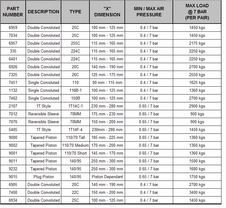
5 C 268C 267C
6 TROUBLE SHOOTING GUIDE Air spring will not inflate Ensure that the air line tubing is inserted into the air fittings as far as possible. Clear any dirt of debris from inside the inflation valves. Inspect the entire length of the air line tubing to ensure that it is not kinked, damaged from exhaust heat, or cut due to contact with sharp edges. Air spring will not hold air Normal pressure loss is no more than 0.3 bar per week when the air spring is inflated to 3.5 bar. Using the inflation valve cap as a core tool, ensure that the valve core is installed securely. Apply a solution of soap and water to the air fittings, air line, and air springs to check for leaks. Tighten the air fittings, air line and air springs to check for leaks. Tighten the air fitting or reinstall the tubing in the air fitting to stop the leak. Rinse the soap and water solution from the system when complete. The vehicle is not level Check for proper inflation of the air springs on each side of the vehicle. Check for obstructions in the air system or vehicle components that may be restricting suspension travel. Finding a stubborn leak If a leak can not be detected with the soap and water solution, deflate the air springs and remove them from the vehicle. Reinstall the tubing and inflate the air spring to a maximum of 1.5 bar. Submerge the air spring in a bucket of water to check for leaks. Common location of air leaks Leaks occur most often at the threaded connection between the air fittings and the air springs. Tighten the fitting to engage at least two threads with the pre-applied orange thread sealant or until the nylon collar makes contact with the air spring, plus ¼ turns, depending on which type of fitting is included in your kit. (See air fittings on page 3) The end of the air line tubing must be cut square and clean to avoid burrs in the connection to the air fittings. The pushto-connect fittings require square cut to properly seal. The tubing can be removed from the fitting by first releasing the air pressure from the air spring. Push the collar on the fitting toward the body of the fitting. While holding the collar in, pull out the tubing. Cut the tubing squarely and push the tubing into the fitting as far as possible.
7 WARRANTY QUESTIONS IS A LEAKING AIR SPRING COVERED UNDER WARRANTY? An air helper spring with a leak does not necessarily indicate that the air spring is defective. Inspect the air spring for obvious punctures or abrasions. A failure caused by a puncture or abrasion to the air spring would not be covered by the material and workmanship warranty. An air helper spring kit that has not been installed according to the published installation manual will not be covered by the warranty. Warranty consideration will only be given if the kit listed in our published application guide is installed on the proper vehicle. WHAT DO I DO IF I HAVE A DEFECTIVE PART THAT IS COVERED UNDER WARRANTY? Call the dealer you purchased your air helper spring kit from to address the warranty claim. If the dealer determines that the warranty claim is questionable, you may need to purchase a replacement part until the warranty claim can be submitted and reviewed by Driverite. If the warranty claim is determined to be a valid claim, a credit for the purchase part will be issued. LIMITED WARRANTY FOR DRIVERITE / RIDE-RITE / SPORT-RITE AIR SPRINGS AND ACCESSORIES Driverite and Firestone Industrial Products Company warrants that Air Suspension Products will be free from defects in workmanship or materials for a period of 24 months or 40,000km (whichever comes first) from the date of installation. This warranty does not cover installation or service charge. For an adjustment under this warranty, contact your local distributor or call Driverite at To the extent permitted by law, we disclaim any consequential damages. Some countries do not allow the exclusion or limitation of incidental or consequential damages, so the above limitation or exclusion may not apply to you. This warranty gives you specific legal rights and you may also have other rights which vary from country to country. Some exclusions may apply. Driverite/ Firestone has made every attempt to assure that your air helper spring kit will properly fit your vehicle. Revised vehicle designs, new model year vehicles, and changes made to the vehicle by the manufacturer can affect proper fit. Any aftermarket chassis or suspension modification made to the vehicle may affect suspension dimensions and may not allow the air helper spring kit to fit the vehicle as intended.
8 To register your Product for warranty please return to Driverite: 1) By Post to: D R I V E R I T E Unit 10 Parkmore Industrial Estate Long Mile Road Dublin 12 Ireland 2) to: eng@driveriteltd.com 3) Fax to: REGISTRATION CARD 1. CUSTOMER INFORMATION 2. PURCHASED FROM NAME ADDRESS NAME ADDRESS Phone: Fax: Phone: Fax: DRIVERITE PRODUCT NUMBER 4 DATE PURCHASED DEALER / INSTALLER STAMP 5 VEHICLE 6 YEAR 7 CHASSIS NUMBER 8 DATE INSTALLED 9 KIT SERIAL NUMBER
OPERATING INSTRUCTIONS AND TROUBLE SHOOTING GUIDE
 A I R H E L P E R S P R I N G S OPERATING INSTRUCTIONS AND TROUBLE SHOOTING GUIDE TM (2071 Shown) (2320 Shown) Thank you for purchasing Firestone air helper springs. You have purchased a quality product
NOTE: PARTS LIST. system to provide equal pressure to both air springs,
 2587 INSTALLATION INSTRUCTIONS Congratulations your new Air Helper Springs are quality products capable of improving the handling and comfort of your vehicle. As with all products, proper installation
INSTALLATION INSTRUCTIONS IMPORTANT! PARTS LIST WARNING:
 2245 WARNING: Do not inflate this assembly when it is unrestricted. The assembly must be restricted by the suspension or other adequate structure. Do not inflate beyond 100 psi. Improper use or over inflation
INSTALLATION INSTRUCTIONS
 2170 / 2456 WARNING: Do not inflate this assembly when it is unrestricted. The assembly must be restricted by the suspension or other adequate structure. Do not inflate beyond 100 P.S.I. Improper use or
WARNING: Installation of this kit requires a minimum of 7-1/2" of clearance between the tire side wall and the frame. INSTALLATION INSTRUCTIONS
 2040 WARNING: Do not inflate this assembly when it is unrestricted. The assembly must be restricted by the suspension or other adequate structure. Once installed, do not inflate beyond 100 psi. Improper
WARNING: INSTALLATION INSTRUCTIONS IMPORTANT! PARTS LIST
 2384 WARNING: Do not inflate this assembly when it is unrestricted. The assembly must be restricted by the suspension or other adequate structure. Do not inflate beyond 100 psi. Improper use or over inflation
INSTALLATION INSTRUCTIONS
 2173 L WARNING: Do not inflate this assembly when it is unrestricted. The assembly must be restricted by the suspension or other adequate structure. Do not inflate beyond 100 P.S.I. Improper use or over
WARNING: INSTALLATION INSTRUCTIONS IMPORTANT! PARTS LIST
 2025 A WARNING: Do not inflate this assembly when it is unrestricted. The assembly must be restricted by the suspension or other adequate structure. Do not inflate beyond 100 P.S.I. Improper use or over
THIS KIT DOES NOT REQUIRE DRILLING INTO THE FRAME.
 2560 THIS KIT DOES NOT REQUIRE DRILLING INTO THE FRAME. WARNING: Do not inflate this assembly when it is unrestricted. The assembly must be restricted by the suspension or other adequate structure. Do
WARNING! INSTALLATION INSTRUCTIONS IMPORTANT! PARTS LIST
 2061 WARNING! Do not inflate this assembly when it is unrestricted. The assembly must be restricted by the suspension or other adequate structure. Do not inflate beyond 100 P.S.I. Improper use or over
WARNING: INSTALLATION INSTRUCTIONS IMPORTANT! PARS LIST
 2293 WARNING: Do not inflate this assembly when it is unrestricted. The assembly must be restricted by the suspension or other adequate structure. Do not inflate beyond 100 P.S.I. Improper use or over
TO BE USED ON A CAB AND CHASSIS TRUCK ONLY. DO NOT USE ON A PICKUP TRUCK.
 TO BE USED ON A CAB AND CHASSIS TRUCK ONLY. DO NOT USE ON A PICKUP TRUCK. 2249 WARNING: Do not inflate this assembly when it is unrestricted. The assembly must be restricted by the suspension or other
2458 / 2459 / 2461 WARNING: INSTALLATION INSTRUCTIONS IMPORTANT! PARTS LIST
 2458 / 2459 / 2461 WARNING: Do not inflate this assembly when it is unrestricted. The assembly must be restricted by the suspension or other adequate structure. Do not inflate beyond 100 psi Improper use
TOOLS REQUIRED UTILITY KNIFE 21MM END WRENCH
 2286 WARNING: Do not inflate this assembly when it is unrestricted. The assembly must be restricted by the suspension or other adequate structure. Once installed, do not inflate beyond 100 psi. Improper
INSTALLATION INSTRUCTIONS IMPORTANT! PARTS LIST WARNING:
 2171 WARNING: Do not inflate this assembly when it is unrestricted. The assembly must be restricted by the suspension or other adequate structure. Do not inflate beyond 100 psi. Improper use or overinflation
INSTALLATION INSTRUCTIONS IMPORTANT! PARTS LIST WARNING:
 2162 WARNING: Do not inflate this assembly when it is unrestricted. The assembly must be restricted by the suspension or other adequate structure. Do not inflate beyond 100 P.S.I. Improper use or over
INSTALLATION INSTRUCTIONS
 2101 WARNING: Do not inflate this assembly when it is unrestricted. The assembly must be restricted by the suspension or other adequate structure. Do not inflate beyond 100 P.S.I. Improper use or over
WARNING! PARTS LIST 01-13
 WARNING! 2080 Do not inflate this assembly when it is unrestricted. The assembly must be restricted by the suspension or other adequate structure. Do not inflate beyond 100 P.S.I. Improper use or over
WARNING: INSTALLATION INSTRUCTIONS IMPORTANT! PARTS LIST
 2176 WARNING: Do not inflate this assembly when it is unrestricted. The assembly must be restricted by the suspension or other adequate structure. Do not inflate beyond 100 P.S.I. Improper use or over
WARNING: INSTALLATION INSTRUCTIONS IMPORTANT! PARTS LIST
 2350 WARNING: Do not inflate this assembly when it is unrestricted. The assembly must be restricted by the suspension or other adequate structure. Do not inflate beyond 100 psi Improper use or over inflation
4X4 ONLY WARNING: DO NOT INSTALL if the truck has been lifted and the stock jounce bumper spacers are not on the vehicle.
 4X4 ONLY DO NOT INSTALL if the truck has been lifted and the stock jounce bumper spacers are not on the vehicle. WARNING: 2400 Do not inflate this assembly when it is unrestricted. The assembly must be
WARNING! INSTALLATION INSTRUCTIONS IMPORTANT! PARTS LIST
 2190 WARNING! Do not inflate this assembly when it is unrestricted. The assembly must be restricted by the suspension or other adequate structure. Do not inflate beyond 100 P.S.I. Improper use or over
BOLT PACK (A ) M10 LOCK WASHER 2 DISK /8"-16 X 1-1/2" HEX BOLTS 8 BRACKET STRAPS
 M10 LOCK WASHER 2 DISK /8-16 X 1-1/2 HEX BOLTS 8 BRACKET STRAPS") 2320 Installation of this kit requires a minimum of 6" of clearance between the tire side wall and the vehicle frame and a 1/2" of clearance around the air spring when inflated. INSTALLATION INSTRUCTIONS
2320 Installation of this kit requires a minimum of 6" of clearance between the tire side wall and the vehicle frame and a 1/2" of clearance around the air spring when inflated. INSTALLATION INSTRUCTIONS
WARNING: Installation of this kit requires a minimum of 7-1/2" of clearance between the tire side wall and the frame. INSTALLATION INSTRUCTIONS
 2264 WARNING: Do not inflate this assembly when it is unrestricted. The assembly must be restricted by the suspension or other adequate structure. Do not inflate beyond 100 P.S.I. Improper use or over
Suspension Leveling Kits HIGH LOW REGULAR. .f. KT ASSEMBLY AND USAGE GUIDE
 Suspension Leveling Kits LOW.f. REGULAR - HIGH t KT 192299 ASSEMBLY AND USAGE GUIDE INTRODUCTION ROCK RIDE Air suspension kits are designed to replace conventional steel springs or shock absorbers of your
PRODUCT SAFETY NOTICE DEALER/INSTALLER NOTICE
 PRODUCT SAFETY NOTICE Congratulations. This vehicle has been equipped with a Firestone air suspension system. This suspension will enhance the vehicle s handling when loaded, however, the vehicle s performance
WARNING: INSTALLATION INSTRUCTIONS IMPORTANT! PARS LIST
 2220 WARNING: Do not inflate this assembly when it is unrestricted. The assembly must be restricted by the suspension or other adequate structure. Do not inflate beyond 100 P.S.I. Improper use or over
Installation Instructions READ INSTALLATION INSTRUCTIONS IN ITS ENTIRETY BEFORE INSTALLING YOUR COIL-RITE KIT
 www.riderite.com 4111 / 4118 4150 / 4156 4164 / 4182 4188 Installation Instructions READ INSTALLATION INSTRUCTIONS IN ITS ENTIRETY BEFORE INSTALLING YOUR COIL-RITE KIT VEHICLE PREPARATION With the vehicle
WARNING: INSTALLATION INSTRUCTIONS IMPORTANT! PARTS LIST
 2350 WARNING: Do not inflate this assembly when it is unrestricted. The assembly must be restricted by the suspension or other adequate structure. Do not inflate beyond 100 psi Improper use or over inflation
WARNING: HARDWARE PACK (A ) DO NOT INSTALL if the truck has been lifted and the stock jounce bumper spacers are not on the vehicle.
 DO NOT INSTALL if the truck has been lifted and the stock jounce bumper spacers are not on the vehicle.") DO NOT INSTALL if the truck has been lifted and the stock jounce bumper spacers are not on the vehicle. 2550 WARNING: Do not inflate this assembly when it is unrestricted. The assembly must be restricted
DO NOT INSTALL if the truck has been lifted and the stock jounce bumper spacers are not on the vehicle. 2550 WARNING: Do not inflate this assembly when it is unrestricted. The assembly must be restricted
4101 / 4102 READ INSTALLATION INSTRUCTIONS IN ITS ENTIRETY BEFORE INSTALLING YOUR COIL-RITE KIT PARTS LIST OPERATING PRESSURES. Figure A DESCRIPTION
 4101 / 4102 READ INSTALLATION INSTRUCTIONS IN ITS ENTIRETY BEFORE INSTALLING YOUR COIL-RITE KIT Figure A PARTS LIST DESCRIPTION QTY. AIR SPRINGS 2 UPPER SUPPORTS 2 LOWER SUPPORTS (BOLT) 2 LOWER SUPPORTS
INSTALLATION INSTRUCTIONS
 2583 INSTALLATION INSTRUCTIONS 7-16 ! IMPORTANT PLEASE DON T HURT YOURSELF, YOUR KIT OR YOUR VEHICLE. TAKE A MINUTE TO READ THIS IMPORTANT INFORMATION. DO NOT INSTALL IF THE TRUCK HAS BEEN LIFTED AND THE
WARNING OPERATING PRESSURES: READ INSTALLATION INSTRUCTIONS COMPLETELY BEFORE INSTALLING YOUR KIT
 4190 www.riderite.com OPERATING PRESSURES: MINIMUM (UNLOADED) MAX (LOADED) 5 PSI 35 PSI READ INSTALLATION INSTRUCTIONS COMPLETELY BEFORE INSTALLING YOUR KIT INSTALLATION INSTRUCTIONS Congratulations your
riderite.com INSTALLATION INSTRUCTIONS
 2528 INSTALLATION INSTRUCTIONS 4-16 ! IMPORTANT PLEASE DON T HURT YOURSELF, YOUR KIT OR YOUR VEHICLE. TAKE A MINUTE TO READ THIS IMPORTANT INFORMATION. This kit is to be used on a pickup truck only, and
INSTALLATION INSTRUCTIONS
 2705 INSTALLATION INSTRUCTIONS 5-6 ! IMPORTANT PLEASE DON T HURT YOURSELF, YOUR KIT OR YOUR VEHICLE. TAKE A MINUTE TO READ THIS IMPORTANT INFORMATION. This kit is to be used on a pickup truck only, and
Ride Rite Warranty Evaluation Guide
 What s covered The Ride-Rite kits, components, and accessories are warranted against defects in workmanship and materials*. What s not covered This warranty does not cover service or labor charges, freight
INSTALLATION INSTRUCTIONS
 270 INSTALLATION INSTRUCTIONS 5-6 ! IMPORTANT PLEASE DON T HURT YOURSELF, YOUR KIT OR YOUR VEHICLE. TAKE A MINUTE TO READ THIS IMPORTANT INFORMATION. This kit is to be used on a pickup truck only, and
Heavy Duty Air Command
 2097 / 2227 Heavy Duty Air Command INSTALLATION INSTRUCTIONS Congratulations on your purchase of a new Air Command kit. This kit was designed to provide inflation control of your air helper springs. This
INSTALLATION INSTRUCTIONS
 2706 INSTALLATION INSTRUCTIONS -6 ! IMPORTANT PLEASE DON T HURT YOURSELF, YOUR KIT OR YOUR VEHICLE. TAKE A MINUTE TO READ THIS IMPORTANT INFORMATION. This kit is to be used on a pickup truck only, and
I. Assembling the Air Spring
 B F H G D FRONT I Assembling the Air Spring 1 Install 90 degree air swivel fitting (D) to the top of the bellow This fitting is precoated with sealant Using an open-end wrench, tighten 1 and 1 /2 turns
INSTALLATION INSTRUCTIONS P/N 59507
 MN-251 (15906) ECN2723 INSTALLATION INSTRUCTIONS P/N 59507 Figure 1 represents a TYPICAL installation. Your vehicle may look slightly different due to make, model or year. Driver Side Only (Left Hand Drive
P/N Retaining Collar. U-BOLT Lower Pedestal REARWARD OUTBOARD
 P/N 59202 MN-406 (01903) NPR2670 1/2" Flat Nut Lock Washer 1/2" Flat Washer Straight Fitting 3/8"x7/8" Hex Head Bolt 3/8" Lock Washer Bell Tech Frame Section Upper Bracket 1/2"-13 x 1.5 " Carriage Bolt
Kit No Please read these instructions completely before proceeding with installation. Air Spring Kit Parts List. Bracket Attaching Hardware
 Kit No. 59532 MN-572 (021108) ECR 7136 Please read these instructions completely before proceeding with installation Air Spring Kit Parts List A Item Description Quantity A Air Sleeves 2 B Upper Brackets
Kit No BT. FOR 6" C NOTCH BELL TECH Please read these instructions completely before proceeding with installation.
 Kit No. 59106BT FOR 6" C NOTCH BELL TECH Please read these instructions completely before proceeding with installation. by MN-283 (061108) ECR 7136 Nylon Lock Nut Large Flat Washer Press Lock Elbow Fitting
Driver Side Shown P/N Figure 1
 P/N 59544 by MN-612 (05606) ECR 5714 Please read these instructions completely before proceeding with the installation. NOTE: Unbolt the lower bracket from the leaf spring if the vehicle is to be serviced
INSTALLATION INSTRUCTIONS
 28 INSTALLATION INSTRUCTIONS SECTION - AIR SPRING SECTION 2 - AIR ACCESSORY 2-5 ! IMPORTANT PLEASE DON T HURT YOURSELF, YOUR KIT OR YOUR VEHICLE. TAKE A MINUTE TO READ THIS IMPORTANT INFORMATION. This
INSTALLATION INSTRUCTIONS
 2807 INSTALLATION INSTRUCTIONS SECTION - AIR SPRING SECTION 2 - AIR ACCESSORY -6 ! IMPORTANT PLEASE DON T HURT YOURSELF, YOUR KIT OR YOUR VEHICLE. TAKE A MINUTE TO READ THIS IMPORTANT INFORMATION. This
Please read these instructions completely before proceeding with the installation. Piston
 P/N 59562 by MN-640 (01506) ECN 5208 Please read these instructions completely before proceeding with the installation. 3/8" Self Tapping Frame Bolts IMPORTANT: Nylon nut must be threaded on the thread
Kit No Please read these instructions completely before proceeding with installation. Parts List G J I K L H CC FF DD MN-505 (01201) NPR 3733
 NPR 3733") Kit No. 57154 MN-505 (01201) NPR 3733 Please read these instructions completely before proceeding with installation Parts List by www.airliftcompany.com Item P/N Description Quantity A 58407 Air Spring
Kit No. 57154 MN-505 (01201) NPR 3733 Please read these instructions completely before proceeding with installation Parts List by www.airliftcompany.com Item P/N Description Quantity A 58407 Air Spring
P/N 59508,Dakota 2WD Models Only
 P/N 59508,Dakota 2WD Models Only by MN-263 (071108) ECR 7136 Please read these instructions completely before proceeding with the installation. 3/8" Nylon Lock Nut Oversized Washer Frame Press Lock Elbow
Light Duty Electronic Air Command
 2491 PSI BAR Light Duty Electronic Air Command INSTALLATION INSTRUCTIONS Congratulations on your purchase of a Light Duty Electronic Air Command kit. This kit was designed to provide inflation control
INSTALLATION INSTRUCTIONS
 2595 INSTALLATION INSTRUCTIONS 2-6 ! IMPORTANT PLEASE DON T HURT YOURSELF, YOUR KIT OR YOUR VEHICLE. TAKE A MINUTE TO READ THIS IMPORTANT INFORMATION. DO NOT INSTALL IF THE TRUCK HAS BEEN LIFTED AND THE
Xtreme Air Command. Step 1 Prepare the components. Step 2 Select a mounting location. Parts list
 2549 60 90 400 600 30 200 120 800 psi 1000 kpa PSI 0 150 Xtreme Air Command Installation instructions Congratulations on your purchase of a new Xtreme Air Command kit. This kit was designed to provide
FIGURE 2 FIGURE 3 AFTER BEFORE
 OUTBOARD Stud Location OUTBOARD Left hand bracket shown - Right hand side opposite Bolt Location Left Hand Side Air Port Left Hand Side UPPER BRACKET ASSEMBLY (Top View) FIGURE 2 FRONT NORMAL RIDE HEIGHT:
AIR CONTROL ACCESSORY KIT
 RAPID RESPONSE SYSTEM 2283 AIR CONTROL ACCESSORY KIT INSTALLATION INSTRUCTIONS Congratulations on your purchase of a new Air Control Accessory Kit. This kit was designed to provide inflation control of
Please read these instructions completely before proceeding with installation. Read all maintenance guidelines on page 7 before operating the vehicle.
 MN-643 (02511) ECR 5461 Kit No. 39205 Please read these instructions completely before proceeding with installation Item P/N Description Quantity A 26391 Driver-Side Beam Assembly 1 B 26414 Passenger-Side
FIGURE 2 FIGURE 3 FIGURE 4
 3/8-16x1.5 WHFB Frame Lockwasher 5/16-18X1 Carriage Bolt Lower Bracket 3/8-16 Locknut Bellows 5/16-18 LockNut Upper Brace 3/8-16x1 HHCS Bolt FLAT WASHER Upper Bracket Elbow Fitting Axle Vent/Brake Line
82-01 Chevy S-10/ GMC Sonoma Front Kit Part No B
 www.airliftcompany.com 82-01 Chevy S-10/ GMC Sonoma Front Kit Part No. 75512B MN-481 (02105) ECN 3549 Please read these instructions completely before proceeding with installation Left Side Upper Shock
Kit No Please read these instructions completely before proceeding with installation. Figure 1. Forward. Passenger-Side View
 Kit No. 57345 90 Air Fitting (G) MN-520 (01206) NPR 3902 Please read these instructions completely before proceeding with installation by www.airliftcompany.com 7 16 "-14 Lock Nut (E) Air Line (AA) Upper
P/N 59511, NEVER EXCEED THE MANUFACTURERS MAXIMUM GROSS VEHICLE WEIGHT RATING. DO NOT INSTALL THE AIR SPRING AS THE PRIMARY SUSPENSION SPRING.
 MN-260 (10901) ECR6622 P/N 59511, 59611 NEVER EXCEED THE MANUFACTURERS MAXIMUM GROSS VEHICLE WEIGHT RATING. DO NOT INSTALL THE AIR SPRING AS THE PRIMARY SUSPENSION SPRING. THIS PRODUCT IS INTENDED FOR
Kit No KIT FITS 2" & 4" DROPS
 Kit No 59104 KIT FITS 2" & 4" DROPS NOTE: If the bottom of the frame to the leaf spring is 70 or less, we do not fit your application Please read these instructions completely before proceeding with installation
INSTALLATION INSTRUCTIONS
 280 INSTALLATION INSTRUCTIONS SECTION - AIR SPRING SECTION 2 - AIR ACCESSORY 2-5 ! IMPORTANT PLEASE DON T HURT YOURSELF, YOUR KIT OR YOUR VEHICLE. TAKE A MINUTE TO READ THIS IMPORTANT INFORMATION. This
Measure and record the Normal Ride Height for later reference. 1. Jack up rear of vehicle or raise on hoist. Place safety jack stands under axle.
 Top View of Lower Bracket INBOARD Use These Holes Flat Washer Lock Washer 3/8-16x 7/8" HHCS INBOARD Air Fitting Port Lower Bracket WARNING: Do not inflate the bellows when they are unrestricted or not
INSTALLATION INSTRUCTIONS
 2806 INSTALLATION INSTRUCTIONS SECTION - AIR SPRING SECTION 2 - AIR ACCESSORY -6 ! IMPORTANT PLEASE DON T HURT YOURSELF, YOUR KIT OR YOUR VEHICLE. TAKE A MINUTE TO READ THIS IMPORTANT INFORMATION. This
Tools Needed. I. Getting Started
 5 /16 ", 7 /16 ", 9 /16 " and 19mm open-end or box wrenches Crescent Wrench Ratchet with 9 /16 " and 1 /2 " deep well sockets 3 /8 " and 5 /16 " drill bits (very sharp) Heavy Duty Drill Torque Wrench Tools
Please read these instructions completely before proceeding with the installation.
 Fits Multi-Leaf Steel Spring Models Only. P/N 59111 This kit is for a 2" drop Please read these instructions completely before proceeding with the installation. by MN-346 (03006) ECN3100 Nylon Nut Upper
Frame. Axle. Kit No Please read these instructions completely before proceeding with installation. Figure 1. Kit Parts List FORWARD B J
 Kit No. 70 Please read these instructions completely before proceeding with installation by www.airliftcompany.com MN-7 (008) ECN 08 Item P/N Description Qty. A B C D E F H I 807 0770 0006 88 70 87 8 8
HP10207 KIT. Ram WD*
 HP10207 KIT Ram 1500 4WD* (For 2WD call customer service 800.663.0096 for assistance) * See application guide for proper fitment. Use the most advanced air springs on the market to eliminate your vehicle
69-74 VW Beetle IRS Rear Kit Part No
 www.airliftcompany.com 69-74 VW Beetle IRS Rear Kit Part No. 75615 MN-476 (01102) ECN 3455 Please read these instructions completely before proceeding with installation A C B E D AA F F ITEM QTY. PART
INSTALLATION INSTRUCTIONS
 4112 TM ead installation instructions in its entirety before installing your Coil-ite Kit SWAY BA LINKAGE LOCATED FOWAD OF THE AXLE MOUNTED TO THE OUTSIDE OF THE FAME AIL EMOVE BOLT ALLOWING SWAY BA TO
Please read these instructions completely before proceeding with the installation. Press Lock Swivel Elbow Fitting. Air Sleeve.
 P/N 59506 Please read these instructions completely before proceeding with the installation. CAUTION: Failure to maintain correct minimum pressure (or pressure proportional to the load), bottoming out,
Kit INSTALLATION GUIDE. For maximum effectiveness and safety, please read these instructions completely before proceeding with installation.
 Kit 25801 MN-208 (121506) ECR 8243 INSTALLATION GUIDE For maximum effectiveness and safety, please read these instructions completely before proceeding with installation. Failure to read these instructions
Kit No Please read these instructions completely before proceeding with installation. Air Spring Kit Parts List. Attaching Hardware
 Kit No. 57340 MN-431 (02409) NPR 4796 Please read these instructions completely before proceeding with installation by www.airliftcompany.com Air Spring Kit Parts List A B1 B2 Item Description Quantity
C-4500 Kit No The Choice of the Professional Installer
 MN-585 (04503) ECR 5047 by C-4500 Kit No. 39023 Please read these instructions completely before proceeding with installation Failure to read these instructions can result in mis-installation Vehicle Requirements...
HP10019 KIT. Universal AMP Air Suspension Kit
 HP10019 KIT Universal AMP Air Suspension Kit Use the most advanced air springs on the market to eliminate your vehicle s sag, sway and bottoming out. Pacbrake air suspension levels your truck s stance
INSTALLATION INSTRUCTIONS
 2802 INSTALLATION INSTRUCTIONS SECTION - AIR SPRING SECTION 2 - AIR ACCESSORY -6 ! IMPORTANT PLEASE DON T HURT YOURSELF, YOUR KIT OR YOUR VEHICLE. TAKE A MINUTE TO READ THIS IMPORTANT INFORMATION. DO NOT
Please read these instructions completely before proceeding with installation. Air Spring Kit Parts List L F. Figure 1
 Kits No. 59561 Please read these instructions completely before proceeding with installation by www.airliftcompany.com MN-629 (01504) NPR 5117 Air Spring Kit Parts List Item Description Quantity A Air
DR W
 Unit 626 Kilshane Avenue, North West Business Park, Ballycoolin, Dublin 15, Ireland Telephone: +353 1 8612 632 Fax: +353 1 8612 647 email:info@driveriteair.com Web: www.driveriteair.com DR.01.014250 W23-760-4250
Figure 1. Figure 2. Figure 3
 BY MN-326 (01611) NPR1952 1. Jack up rear of vehicle or raise on hoist. Support frame with safety stands. Remove lower shock absorber attaching bolts. 2. Carefully lower axle or raise body of the vehicle
HP10033 KIT. * See application guide for proper fitment.
 HP10033 KIT * See application guide for proper fitment. Use the most advanced air springs on the market to eliminate your vehicle s sag, sway and bottoming out. Pacbrake air suspension levels your truck
Kit No Please read these instructions completely before proceeding with installation. Air Spring Kit Parts List. Bracket Attaching Hardware
 Kit No. 59537 MN-461 (021108) ECR 7136 Please read these instructions completely before proceeding with installation Air Spring Kit Parts List Item Description Quantity A Air Sleeves 2 B Upper Brackets
Tools Needed. I. Getting Started
 7 /16 ", 9 /16 " open-end or box wrenches Crescent Wrench Ratchet with 3 /8 ", 9 /16 " and 1 /2 " deep well sockets 3 /8 " and 5 /16 " drill bits (very sharp) 3 /8 " Nut Driver Heavy Duty Drill Torque
FIGURE 2 FIGURE Remove the rubber jounce bumper. This will not be reused.
 3/8-16x1.5" WHFB Upper Brace Frame Lockwasher 5/16-18x1 1/2" Carriage Bolt Straight end 3/8-16 Locknut 3/8 Lockwasher 3/8-16x1" HHCS 5/16-18 Lock Nut Bellows 5/16 Flatwasher 3/8-16x1" HHCS FIGURE 2 Upper
I. Preparing the Vehicle
 Multiple Applications See special notes for your particular vehicle. I. Preparing the Vehicle by MN-169 (11809) ECR 6529 NOTE For Toyota Sequoias: Before proceeding with the installation, measure up 6.75
Kit No Please read these instructions completely before proceeding with installation Air Spring Unit Parts List. Mounting Hardware Parts List
 Kit No. 59531 by MN-435 (01003) ECN 2794 Please read these instructions completely before proceeding with installation Air Spring Unit Parts List Item Description Quantity A Air Spring 2 B Upper Bracket
KIT # Figure 1. Figure 2. Figure 3
 KIT #60748 BY MN-330 (02809) ECR6529 1. Jack up rear of vehicle or raise on hoist. Support frame with safety stands. Remove lower shock absorber attaching bolts. CUT BOTTOM (2) SECTIONS OFF RUBBER BUMP
PRO COMP SUSPENSION PART# F-150 ADD-A-LEAF KIT. Suspension Systems that Work!
 2360 Boswell Road Chula Vista, CA 91914 Phone 619.216.1444 Fax 619.216.1474 E-Mail tech@explorerprocomp.com PRO COMP SUSPENSION Suspension Systems that Work! PART# 13134 2004 F-150 ADD-A-LEAF KIT This
AIR SUSPENSION KIT HP UNIVERSAL AIR SUSPENSION KIT
 AIR SUSPENSION KIT HP10019 - UNIVERSAL AIR SUSPENSION KIT KIT CONTENTS A A D B Make sure all the items shown in the photo are provided in your kit before starting the installation. J V III D D D VII I
Kit Number INSTALLATION GUIDE ADJUSTABLE AIR HELPER SPRINGS TOW AND HAUL WITH SAFETY AND COMFORT TM
 ADJUSTABLE AIR HELPER SPRINGS TOW AND HAUL WITH SAFETY AND COMFORT TM Kit Number 88205 INSTALLATION GUIDE For maximum effectiveness and safety, please read these instructions completely before proceeding
JEEP WRANGLER 2 & 4 DOOR (JK) 2.5 SPACER KIT KIT# TM /TM
 2.5 SPACER KIT KIT# TM /TM") 400 W. Artesia Blvd. Fax: (310) 747-3912 Compton, CA 90220 Ph: (877) 695-7812 www.trailmastersuspension.com JEEP WRANGLER 2 & 4 DOOR (JK) 2.5 SPACER KIT 07-13 KIT# TM3325-40010/TM3325-40013 Installation
400 W. Artesia Blvd. Fax: (310) 747-3912 Compton, CA 90220 Ph: (877) 695-7812 www.trailmastersuspension.com JEEP WRANGLER 2 & 4 DOOR (JK) 2.5 SPACER KIT 07-13 KIT# TM3325-40010/TM3325-40013 Installation
Figure 1. Figure 2. Figure 3. Air Line. Large Spacer
 BY MN-285 (02706) ECN2200 Large Spacer Figure 1 Figure 2 1. Jack up rear of vehicle or raise on hoist. Support frame with safety stands. Remove lower shock absorber attaching bolts. 2. Carefully lower
Please read these instructions completely before proceeding with installation. Existing ABS/Brake Line Bracket J I. Outboard
 Kit No. 59560 Please read these instructions completely before proceeding with installation by www.airliftcompany.com MN-558 (02312) ECN 4429 Air Spring Kit Parts List Item Description Quantity A Air Sleeve
Tools Needed. I. Assembling the Unit
 1 /2 ", 9 /16 " open-end or box wrenches Crescent Wrench Ratchet with 9 /16 " and 1 /2 " deep well sockets 5 /16 " drill bits (very sharp) Heavy Duty Drill Torque Wrench Hose Cutter, Razor Blade, or Sharp
INSTALLATION INSTRUCTIONS
 2581 INSTALLATION INSTRUCTIONS 08-15 IMPORTANT PLEASE DON T HURT YOURSELF, THE KIT, OR YOUR VEHICLE. TAKE A MINUTE TO READ THIS IMPORTANT INFORMATION. SAFE INSTALLATION Please take all safety precautions
For Multiple Applications See special notes for your particular vehicle.
 For Multiple Applications See special notes for your particular vehicle. by MN-131 (10304) ECN4192 Please read these instructions completely before proceeding with the installation. Escort, Lynx Escort
JEEP CHEROKEE (XJ) 3 SPRING KIT TM w/ Rear Add-A-Leaf & TM w/ Rear Leaf Spring
 3 SPRING KIT TM w/ Rear Add-A-Leaf & TM w/ Rear Leaf Spring") 400 W. Artesia Blvd. Fax: (310) 747-3912 Compton, CA 90220 Ph: (877) 695-7812 www.trailmastersuspension.com JEEP CHEROKEE (XJ) 3 SPRING KIT 84-01 TM3730-40013 w/ Rear Add-A-Leaf & TM3730-40023 w/ Rear
400 W. Artesia Blvd. Fax: (310) 747-3912 Compton, CA 90220 Ph: (877) 695-7812 www.trailmastersuspension.com JEEP CHEROKEE (XJ) 3 SPRING KIT 84-01 TM3730-40013 w/ Rear Add-A-Leaf & TM3730-40023 w/ Rear
No INSTALLATION GUIDE. Chevrolet Silverado 1500 and GMC Sierra 1500
 No. 59565 Chevrolet Silverado 1500 and GMC Sierra 1500 INSTALLATION GUIDE MN-670 (01701) For maximum effectiveness and safety, please read these instructions completely before proceeding with installation.
Kit 59565, Chevrolet Silverado 1500 and GMC Sierra 1500
 Kit 59565, 59567 Chevrolet Silverado 1500 and GMC Sierra 1500 MN-670 (061706) ECR 8870 INSTALLATION GUIDE For maximum effectiveness and safety, please read these instructions completely before proceeding
INSTALLATION INSTRUCTIONS Air Spring Kit Dodge WD IMPORTANT NOTES
 INSTALLATION INSTRUCTIONS 6211 Air Spring Kit 2003+ Dodge 1500 4WD Thank you for purchasing a quality Hellwig Product. PLEASE READ THIS INSTRUCTION SHEET COMPLETELY BEFORE STARTING YOUR INSTALLATION IMPORTANT
P/N Figure 1. Figure 2. 3 Valve Stem
 P/N 80523 BY MN-75 (12612) ECN1965 3 Valve Stem 2 1 Figure 1 1 1. Jack up front end of vehicle and place safety stands under axle. Remove front wheels and lower shock absorber attaching bolts. 2. Remove