L.IVE.S.14.C.L (RWD Single Tire) Iveco Daily S (2014 Onwards)
|
|
|
- Crystal Briana Lynch
- 6 years ago
- Views:
Transcription


1 Auxiliary Air Suspension Installation Manual (RWD Single Tire) Iveco Daily S (2014 Onwards) July 2015
2 CONTENTS 1. FOREWORD INTRODUCTION VERY IMPORTANT NOTES OVERVIEW INSTRUCTIONS FOR INSTALLATION Preparation Installation of the air suspension Fitting of Inflator Console Tube Connection and Disconnection, Cutting and Routing Spring Inflation Spring Alignment Maintenance Check List INSTALLATION PHOTOS EPILOGUE Dunlop Systems and Components Het Wegdam CA Hengevelde Nederland Tel. : +31 (0) Fax. : +31 (0) info@dunlopsystems.nl Website: 2014, Dunlop Systems and Components 2
3 1. FOREWORD This manual provides instructions for the installation of an auxiliary air suspension kit, developed specifically for the Iveco Single Rear Wheel Drive (2014 onwards). To ensure correct installation of the kit, it is strongly recommend that these instructions are read thoroughly before commencing any installation work. Installation should only be carried out by a suitably qualified mechanic or specialist installation facility. Dunlop Systems and Components will not accept any responsibility for faults or defects arising from incorrect installation, which automatically renders the guarantee invalid. 3
4 2. INTRODUCTION Thank you for choosing an auxiliary air suspension kit from the range offered by Dunlop Systems and Components. Auxiliary air suspension is fitted in tandem with the standard steel springs of the vehicle suspension, and provides enhancements in terms of both the stability of the vehicle and the comfort of the passengers Vehicle Levelling Simply by varying the air pressure in the springs, the vehicle can be levelled both front-to-rear and side-to-side. Keeping the vehicle level optimises stability, ensures correct headlamp beam distribution and reduces tyre wear arising from uneven distribution of weight. Straight Line Stability Straight line stability is greatly increased at higher speeds, and when subjected to buffeting from cross-winds or large overtaking vehicles. Reduced Body Roll Body roll when cornering or negotiating roundabouts is significantly reduced. Fatigue Reduction and Wear Compensation Suspension fatigue is reduced, so helping to prevent leaf springs from sagging under repeated or constant loading. Any sagging already present can be compensated-for. This is a particular benefit for motorhomes, which are always fully laden. Ride Comfort Air springs help to absorb shock loads from uneven road surfaces, therefore general ride quality is much improved. 4
5 3. VERY IMPORTANT NOTES Gross Vehicle Weight (GVW) Air assist kits are not in themselves designed to increase the gross vehicle weight (GVW) rating of a vehicle. They do not legally allow for carriage of a load greater than the carrying capacity stated on the data plate of the vehicle. Do not exceed the maximum load specified by the vehicle manufacturer to avoid compromising passenger safety to prevent possible damage to the vehicle for legal reasons Vehicle Uprating Despite the above words of caution, it is possible to upgrade the weight rating of your vehicle. This must be carried-out by a specialist supplier that will carry out any necessary modifications in addition to fitting the air assist kit complete documentation as necessary to inform the Vehicle and Operator Services Agency (VOSA) a mandatory requirement supply and fit a new weight plate to replace the original plate supplied with the vehicle This process applies to United Kingdom registered vehicles. The process in other countries may be different. This process applies to United Kingdom registered vehicles. The process in other countries may be different. Safety Guidance Note The following very useful guidance note is available for free download from the Health and Safety Executive (HSE) PM85, July 2007 Safe recovery (and repair) of buses and coaches fitted with air suspension The uniform resource locator (URL) for this document is 5

6 4. OVERVIEW Number Part Number Description Quantity Top bracket right Top bracket le Lower bracket le and right 2 4 OP.LB CPL Air bellow 130/3 2 5 DIN 933 M6x20 Hexagon bolt M6 x DIN 127 M6 Spring washer 6mm 8 7 DIN 9021 M6x20 Washer 6 x DIN 125A M6 Washer M6 4 9 DIN 933 M8x20 Hexagon bolt M8 x DIN 125A M8 Washer M DIN 985 M8 Self locking nut M Not in the assembly drawing... Tie wraps Inflate valves (or option) Declaration of conformity Installation manual 6

7 5. INSTRUCTIONS FOR INSTALLATION Preparation and Precaution Before beginning installation, ensure that you have sufficient clearance between the axle and the chassis. Use a jack if necessary. Install at one side of the vehicle at a time. Pay attention to your safety at all times during installation - always use axle stands to support the vehicle! The position of the axle stands should be under the chassis NOT under the axle! Recommended Tightening Torque During fitting of the air suspension system, it is recommended that nuts and bolts are tightened in accordance with the following table... METRIC TORQUE CHART IN N.m SIZE CLASS 8.8 CLASS 10.9 M6 x M8 x M10 x M12 x M16 x When both the bolt and nut are made from steel use either class 8.8 or 10.9 For all other materials, tightening torque is left to the discretion of a person skilled in the art The following instructions make reference to the diagrams on pages 16 to 18 inclusive. 5.1 Preparation i. Secure the front wheels, use wheel chocks on both sides of both front wheels. ii. Take the ground terminal from the battery when work to electricity is involved. iii. Lift the rear of the vehicle till there is working space of approximately 25 cm between bump stop and rear axle. 7
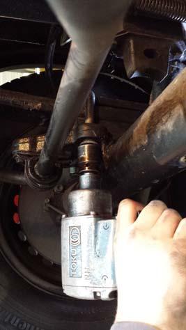
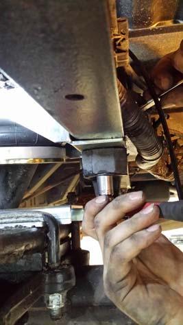
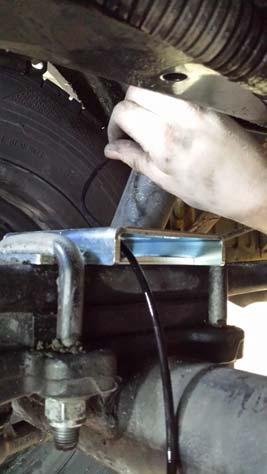
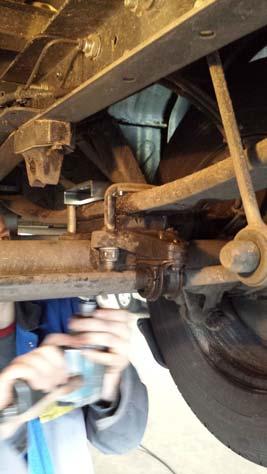
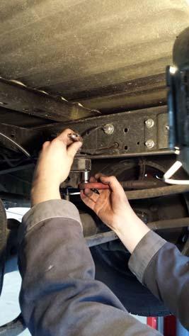
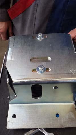
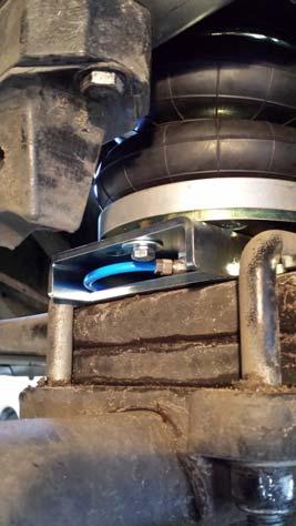
8 5.2 Installation of the air suspension i. Study the location where the air suspension should be installed. To ensure yourself if our kit will fit (photo 1). ii. Ensure that the axle can lower 5 mm as a maximum when the U- bolts are dismounted. iii. if no technical manual is available, determine by yourself the tightening torque of the U-bolts, before unscrewing the U-bolts (photo 2). iv. The metal plate that is originally used under the U-bolts will not be reused. v. Install the lower bracket with the longest part to the outside and ensure it s well positioned (photo 3). vi. Tighten the U-bolts with the correct torque (photo 3). vii. Check if the lower bracket is still in a correct position. viii. Remove the bump stop (photo 4). It will be reused. The M8 bolts will also be reused to attach later the upper bracket (photo 4). ix. Attach the air bellow with the side without the nipple to the upper bracket 9photo 5), the nipple should point inwards. Use M6x 20 bolts spring washers and the washers 6 x 20. x. Bring the hose (black is left and blue is right) from the inside inbetween the lower bracket (photo 6) through the big hole of the lower bracket and attach it to the air bellow. For air hose connection instructions see section 5.4. xi. If there should be too less space to install the upper bracket together with the air bellow, than push out the air out of the air bellow bend the last 5 cm of the air hose and pull a tie wrap around it to keep the air hose closed. The air bellow will remain compressed now. xii. Bring the air bellow (with installed upper bracket) on top of the lower bracket (photo 7). xiii. Position the upper bracket and reinstall the bump stop. Don t tighten the bolts but without play (photo 9). xiv. Install the M8 x 20 bolt and washer from the outside to the inside and use a washer and a self locking nut on the inside. Also finger tight and without play (photo 10). xv. Tighten the bolts of the bump stop and afterwards the bolt in the side of the upper bracket. 8
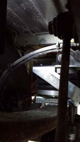
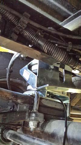
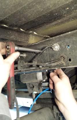
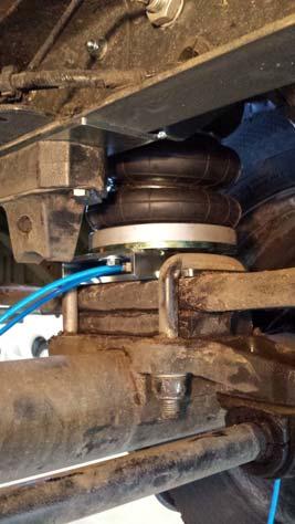
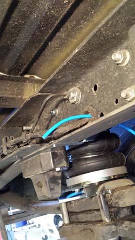
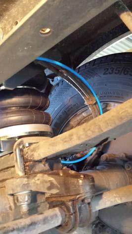
9 xvi. Remove now the tie wrap at the and of the hose and and connect the air bellow to the lower bracket. Use M6 x 20 bolt with spring washers and washers 6 x 20 (photo 11) and tighten them finger tight and without play. xvii. Install the wheel (if you had removed it). xviii.lower the vehicle (bridge up) till a distance of approximately 16 cm...17 cm between the upper and lower bracket (that s app. drive height). Now align the air bellow and tighten the bolts (photo 12). xix. Guide the air hose through the lower bracket from the inside to the outside and give it a large loop (photo 13). Now you can guide the air hose along the cable of the Abs sensor through the chassis to the middle of the vehicle (photo 14 and 15). xx. Now you can guide the air hose according section


 and two for")


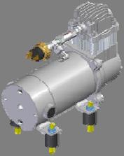
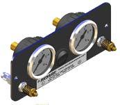
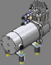
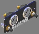
10 5.3 Fitting of Inflator Console Iveco Daily S STANDARD OPTION 1 OPTION 2 OPTION 3 Your kit is supplied with one of the inflator console options shown above STANDARD : Two valves and a small bracket OPTION 1 OPTION 2 OPTION 3 : Two valves in a console with two independent 10-bar pressure gauges : Two valves in a console with two independent 10-bar pressure gauges and a rocker on/off switch to operate the electric motor driven air compressor : Four valves (two for raising the vehicle ( UP ) and two for lowering the vehicle ( DOWN )) in a console with two independent 10-bar pressure gauges. A pressure switch operates the electric motor driven air compressor to keep the air reservoir of 2.2-litre at pressure. A special dashboard panel is available for OPTION 1 and OPTION 2 10

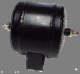
11 Mount the console in a position of your choice whereby it is firmly fixed, has some protection from the environment (particularly important for the console with gauges) and is easily accessible. Suggested possible locations include... Standard Console on the rear bumper at the rear beside the license plate on the chassis next to a rear wheel in a service shutter (motorhomes) beside the fuel cap Option 1, Option 2 or Option 3 Console in the vehicle cabin, within reach and sight of the driver Beside, under the driver seat in the wall of a cupboard (motorhomes) in a service shutter (motorhomes) Comfort Packages The Option 2 and Option 3 panels, as shown above, are each part of a Comfort Package that is supplied with a compressor (and also an air reservoir in the case of the Option 3 panel) for ease of spring inflation and ride height setting. For further information please ask your dealer. The photograph below shows all of the parts of Comfort Package Option 2... Comfort Package Option 2 11


12 5.4 Tube Connection and Disconnection, Cutting and Routing Connection and Disconnection Tubes are connected as shown by the diagrams below... A B C A. Slide a nut over the end of the tube B. Push the tube onto the connector as far as possible C. Feed the nut up to the connector, fully tighten by hand and finally tighten one additional turn using spanners Cutting To achieve good sealing and air-tight fitting of tube ends to their connecting parts, it is very important to cut tubing cleanly and squarely. A dedicated guillotine action tubing cutter is recommended, or a craft knife if such a tool is not available. Do not use electrician s side cutters. A dedicated tubing cutter - Recommended Electrician s Side Cutters NOT Recommended 12
13 Routing Study the underside of the vehicle and decide how to route each branch of the air circuit To minimise the risk of chafing, avoid running tubing over metal edges as much as possible Avoid close proximity to heat sources such as the exhaust assembly Choose a route that provides as much protection as possible from dirt, debris and any solid objects that may impact the underside of the vehicle It is recommended that tubes are guided alongside brake lines as much as possible. Use cable ties ( tie wraps ) to secure tubing to the chassis, taking care not to over-tighten them. 5.5 Spring Inflation Once installation of the air assist kit is complete, inflate the springs to achieve the desired ride height via the inflator console taking careful note of the following... Maximum and Minimum Pressure Maximum Pressure 7.0bar Minimum Pressure 0.5bar Do not exceed 7.0bar (101psi), which is the recommended maximum charge pressure for the air springs. The springs may be deflated if the vehicle is to be stored for a lengthy period without use, but a pressure of at least 0.5bar (7.25psi) should be maintained at all times in order to avoid possible compression damage to the springs. With the vehicle standing at the desired ride height, it is recommended that the height of the bellow itself should be between 18cm and 22cm. 13

14 5.6 Spring Alignment Spring out of alignment mounting plate axes offset Spring in alignment mounting plates parallel and coaxial i. With the vehicle standing at the desired ride height, ensure that the springs are correctly aligned as illustrated above and then tighten the bolts to secure the bellow to both the upper and the lower mounting brackets. ii. Always check if the air bellow won t touch any obstacle 5.7 Maintenance Following installation, it is recommended that all metal parts are coated with a protective substance such as body wax. The system does not require very much maintenance other than to maintain air pressure in the springs. Much like a tyre, the system may lose a little air over time. to keep the air bellows clean. It is suggested that, when washing the vehicle, the bellows are inspected and cleaned as necessary (preferable by spraying). Look in particular for stones or grit trapped between convolutes, as this may damage the bellow. Check before and after the winter period the wax coating. Re-wax when necessarily 14
?...air springs set in alignment (Section 5.6)?...enough free space around the air springs to avoid wearing?")
15 2 Iveco Daily S 5.8 Check List Before driving the vehicle following completion of installation of the auxiliary air suspension system, please check......all bolts tightened to the recommended torque (Page 7)?...air springs set in alignment (Section 5.6)?...enough free space around the air springs to avoid wearing?...all metal parts wax coated (Section 5.7)?...manufacturer s declaration form completed and a copy returned? A wait of 24 hours is recommended in order to ensure that the vehicle has maintained its stance and that there are no air leaks present. 15

16 6. INSTALLATION PHOTOS 16

17

18
19 6. EPILOGUE Dunlop Systems and Components hopes that you enjoy the benefits that your air suspension system will provide for you. To ensure optimal performance, we advise that you have your system checked frequently by qualified personnel. As recommended in the fitting instructions, it is important to coat all the steel parts with a protective substance such as body wax. IMPORTANT : Manufacturer s Declaration Form A manufacturer s declaration form is provided with your kit. Following installation of the kit please ensure that this form is completed, signed by a qualified fitter and a copy is returned to Dunlop Systems and Components. As a condition of your warranty, modifications to the system may only be carried out by personnel of Dunlop Systems and Components. Enquiries For general enquiries please contact one of our dealers. You can find them on our website. 19
20 Auxiliary Air Suspension Dunlop Systems and Components Het Wegdam CA Hengevelde Nederland Tel. : +31 (0) Fax. : +31 (0) info@dunlopsystems.nl
L.IVE.LS.C.M (RWD Single Tire) Iveco Daily L and S (2005)
 Iveco Daily L and S (2005)") Auxiliary Air Suspension Installation Manual (RWD Single Tire) Iveco Daily L and S (2005) November 2018 CONTENTS 1. FOREWORD... 3 2. INTRODUCTION... 4 3. VERY IMPORTANT NOTES... 5 4. INSTRUCTIONS FOR INSTALLATION...
Auxiliary Air Suspension Installation Manual (RWD Single Tire) Iveco Daily L and S (2005) November 2018 CONTENTS 1. FOREWORD... 3 2. INTRODUCTION... 4 3. VERY IMPORTANT NOTES... 5 4. INSTRUCTIONS FOR INSTALLATION...
Auxiliary Air Suspension. Installation Manual L.NAV.05.C.M. Nissan Navara (D40) May 2009
 May 2009") Auxiliary Air Suspension Installation Manual (D40) May 2009 CONTENTS 1. FOREWORD...3 2. INTRODUCTION...4 3. VERY IMPORTANT NOTES...5 4. COMPLETE ASSEMBLY...7 5. INSTRUCTIONS FOR INSTALLATION...8 5.1. Installation
Auxiliary Air Suspension Installation Manual (D40) May 2009 CONTENTS 1. FOREWORD...3 2. INTRODUCTION...4 3. VERY IMPORTANT NOTES...5 4. COMPLETE ASSEMBLY...7 5. INSTRUCTIONS FOR INSTALLATION...8 5.1. Installation
Installation Manual L.MAS.10.C.M. Nissan NV400, 2010 Onwards Opel, Vauxhall Movano 2, 2010 Onwards Renault Master X Onwards
 Auxiliary Air Suspension Installation Manual Nissan NV400, 2010 Onwards Opel, Vauxhall Movano 2, 2010 Onwards Renault Master X62 2010 Onwards November 2018 CONTENTS 1. FOREWORD... 3 2. INTRODUCTION...
L.L200.2.C.M L.L200.4.C.M Mitsubishi L200 Two - and Four - wheel Drive ( )
") Auxiliary Air Suspension Installation Manual L.L200.2.C.M L.L200.4.C.M Mitsubishi L200 Two - and Four - wheel Drive (1991-2006) November 2018 CONTENTS 1. FOREWORD... 3 2. INTRODUCTION... 4 3. VERY IMPORTANT
Auxiliary Air Suspension Installation Manual L.L200.2.C.M L.L200.4.C.M Mitsubishi L200 Two - and Four - wheel Drive (1991-2006) November 2018 CONTENTS 1. FOREWORD... 3 2. INTRODUCTION... 4 3. VERY IMPORTANT
Auxiliary Air Suspension. Installation Manual L.HI.L4.C.M. Toyota Hilux 4 WD. May 2011
 Auxiliary Air Suspension Installation Manual Toyota Hilux 4 WD May 2011 CONTENTS 1. FOREWORD... 3 2. INTRODUCTION... 4 3. VERY IMPORTANT NOTES... 5 4. COMPLETE ASSEMBLY... 7 5. INSTRUCTIONS FOR INSTALLATION...
L.312.C.M. Auxiliary Air Suspension. Installation Manual. Mercedes Benz Sprinter 200/300 Series ( ) Volkswagen LT ( )
 Volkswagen LT ( )") Auxiliary Air Suspension Installation Manual Mercedes Benz Sprinter 200/300 Series (1995 2006) Volkswagen LT 28-35 (1995 2006) November 2008 CONTENTS 1. FOREWORD...3 2. INTRODUCTION...4 3. VERY IMPORTANT
Auxiliary Air Suspension Installation Manual Mercedes Benz Sprinter 200/300 Series (1995 2006) Volkswagen LT 28-35 (1995 2006) November 2008 CONTENTS 1. FOREWORD...3 2. INTRODUCTION...4 3. VERY IMPORTANT
L.D84.C.M. Auxiliary Air Suspension. Installation Manual
 Auxiliary Air Suspension Installation Manual Citroën Jumper / Relay X280/X290 (1984 1993) Fiat Ducato X280/X290 (1984 1993) Peugeot Boxer X280/X290 (1984 1993) November 2008 CONTENTS 1. FOREWORD... 3 2.
L.MAS.10D.C.M (RWD Single and Double tire)
") Auxiliary Air Suspension Installation Manual (RWD Single and Double tire) Nissan NV400, 2010 Onwards Opel, Vauxhall Movano 2, 2010 Onwards Renault Master X62 2010 Onwards August 2012 CONTENTS 1. FOREWORD...
Auxiliary Air Suspension Installation Manual (RWD Single and Double tire) Nissan NV400, 2010 Onwards Opel, Vauxhall Movano 2, 2010 Onwards Renault Master X62 2010 Onwards August 2012 CONTENTS 1. FOREWORD...
L.D94.C.M(.A) Auxiliary Air Suspension. Installation Manual
 Auxiliary Air Suspension. Installation Manual") Auxiliary Air Suspension Installation Manual L.D94.C.M(.A) Citroën Jumper / Relay X230 (1994 2002) Fiat Ducato X230 (1994 2002) Peugeot Boxer X230 (1994 2002) December 2008 CONTENTS 1. FOREWORD... 3 2.
Auxiliary Air Suspension Installation Manual L.D94.C.M(.A) Citroën Jumper / Relay X230 (1994 2002) Fiat Ducato X230 (1994 2002) Peugeot Boxer X230 (1994 2002) December 2008 CONTENTS 1. FOREWORD... 3 2.
Auxiliary Air Suspension. Installation Manual. L.IVE.35.C.M & L.IVE.C.C.M Iveco Daily 30-8 / ( ) Iveco Daily 35C / 55C (1999 onwards)
 Iveco Daily 35C / 55C (1999 onwards)") Auxiliary Air Suspension Installation Manual L.IVE.35.C.M & L.IVE.C.C.M Iveco Daily 30-8 / 49-12 (1985 1999) (1999 onwards) December 2011 CONTENTS 1. FOREWORD... 3 2. INTRODUCTION... 4 3. VERY IMPORTANT
Auxiliary Air Suspension Installation Manual L.IVE.35.C.M & L.IVE.C.C.M Iveco Daily 30-8 / 49-12 (1985 1999) (1999 onwards) December 2011 CONTENTS 1. FOREWORD... 3 2. INTRODUCTION... 4 3. VERY IMPORTANT
L.D02.C.M(.A) Installation Manual. Citroën Jumper X244, Fiat Ducato X244, Peugeot Boxer X244, Auxiliary Air Suspension
 Installation Manual. Citroën Jumper X244, Fiat Ducato X244, Peugeot Boxer X244, Auxiliary Air Suspension") Auxiliary Air Suspension Installation Manual L.D02.C.M(.A) Citroën Jumper X244, 2002 2006 Fiat Ducato X244, 2002 2006 Peugeot Boxer X244, 2002 2006 December 2008 CONTENTS 1. FOREWORD... 3 2. INTRODUCTION...
Auxiliary Air Suspension Installation Manual L.D02.C.M(.A) Citroën Jumper X244, 2002 2006 Fiat Ducato X244, 2002 2006 Peugeot Boxer X244, 2002 2006 December 2008 CONTENTS 1. FOREWORD... 3 2. INTRODUCTION...
Auxiliary Air Suspension. Installation Manual L.AL.02. AL-KO Chassis June 2009
 Auxiliary Air Suspension Installation Manual AL-KO Chassis 2002 2006 June 2009 CONTENTS 1. FOREWORD... 3 2. VERY IMPORTANT PREREQUISITES... 4 3. INTRODUCTION... 5 4. VERY IMPORTANT NOTES... 5 5. CONTENTS
AIR-SUSPENSION. Designed for: Alko Chassis
 AIR-SUSPENSION Dunlop Systems and Components Het Wegdam 22 7496 CA Hengevelde The Netherlands Tel.: +31-(0)547-333065 Fax: +31-(0)547-333068 Website: www.dunlopsystems.com Art. nr.: L.AL.02 Designed for:
AUXILIARY AIR SUSPENSION KITS
 KITS UK AGENT Marcle Leisure Huntley s Farm Lane, Much Marcle Herefordshire. HR8 2NB Tel: 01531 660797 Fax: 01531 660462 www.marcleleisure.co.uk Draft Copy July 2008 CONTENTS Introduction...4 Very Important
AIR-SUSPENSION. Art. nr.: L.DOBLO.CM. Auxiliary Air Suspension. Designed for: Fiat Doblo. From: 2001 & UP RDW 71/
 AIR-SUSPENSION Dunlop Systems and Components Het Wegdam 22 7496 CA Hengevelde The Netherlands Tel.: +31-547-333065 Fax: +31-547-333068 Website: www.dunlopsystems.com Art. nr.: L.DOBLO.CM Designed for:
AIR SUSPENSION Edition 2014
 AIR SUSPENSION Edition 2014 CONTENTS Introduction... 4 Very Important Notes... 5 Inflation Options... 7 The Product Range... 10 Guide to the Product Pages of this Catalogue... AL-KO Chassis Solutions...
Kit No Please read these instructions completely before proceeding with installation. Air Spring Kit Parts List. Attaching Hardware
 Kit No. 57340 MN-431 (02409) NPR 4796 Please read these instructions completely before proceeding with installation by www.airliftcompany.com Air Spring Kit Parts List A B1 B2 Item Description Quantity
Kit No Please read these instructions completely before proceeding with installation. Parts List G J I K L H CC FF DD MN-505 (01201) NPR 3733
 NPR 3733") Kit No. 57154 MN-505 (01201) NPR 3733 Please read these instructions completely before proceeding with installation Parts List by www.airliftcompany.com Item P/N Description Quantity A 58407 Air Spring
Kit No. 57154 MN-505 (01201) NPR 3733 Please read these instructions completely before proceeding with installation Parts List by www.airliftcompany.com Item P/N Description Quantity A 58407 Air Spring
82-01 Chevy S-10/ GMC Sonoma Front Kit Part No B
 www.airliftcompany.com 82-01 Chevy S-10/ GMC Sonoma Front Kit Part No. 75512B MN-481 (02105) ECN 3549 Please read these instructions completely before proceeding with installation Left Side Upper Shock
I. Assembling the Air Spring
 B F H G D FRONT I Assembling the Air Spring 1 Install 90 degree air swivel fitting (D) to the top of the bellow This fitting is precoated with sealant Using an open-end wrench, tighten 1 and 1 /2 turns
Please read these instructions completely before proceeding with installation. Read all maintenance guidelines on page 7 before operating the vehicle.
 MN-643 (02511) ECR 5461 Kit No. 39205 Please read these instructions completely before proceeding with installation Item P/N Description Quantity A 26391 Driver-Side Beam Assembly 1 B 26414 Passenger-Side
69-74 VW Beetle IRS Rear Kit Part No
 www.airliftcompany.com 69-74 VW Beetle IRS Rear Kit Part No. 75615 MN-476 (01102) ECN 3455 Please read these instructions completely before proceeding with installation A C B E D AA F F ITEM QTY. PART
Tools Needed. I. Getting Started
 5 /16 ", 7 /16 ", 9 /16 " and 19mm open-end or box wrenches Crescent Wrench Ratchet with 9 /16 " and 1 /2 " deep well sockets 3 /8 " and 5 /16 " drill bits (very sharp) Heavy Duty Drill Torque Wrench Tools
Frame. Axle. Kit No Please read these instructions completely before proceeding with installation. Figure 1. Kit Parts List FORWARD B J
 Kit No. 70 Please read these instructions completely before proceeding with installation by www.airliftcompany.com MN-7 (008) ECN 08 Item P/N Description Qty. A B C D E F H I 807 0770 0006 88 70 87 8 8
Kit No Please read these instructions completely before proceeding with installation. Air Spring Kit Parts List. Bracket Attaching Hardware
 Kit No. 59532 MN-572 (021108) ECR 7136 Please read these instructions completely before proceeding with installation Air Spring Kit Parts List A Item Description Quantity A Air Sleeves 2 B Upper Brackets
KIT No , and 80590
 KIT No. 80531, 80545 and 80590 by MN-354 (05603) ECR 5593 Please read these instructions completely before proceeding with installation Air Spring Kit Parts List Item Description Quantity A Air Spring
Kit No Please read these instructions completely before proceeding with installation. Figure 1. Forward. Passenger-Side View
 Kit No. 57345 90 Air Fitting (G) MN-520 (01206) NPR 3902 Please read these instructions completely before proceeding with installation by www.airliftcompany.com 7 16 "-14 Lock Nut (E) Air Line (AA) Upper
Kit No Please read these instructions completely before proceeding with installation. Figure 1 MN-614 (06601) ECR
 ECR") Kit No. 57291 MN-614 (06601) ECR 5445 Please read these instructions completely before proceeding with installation. by www.airliftcompany.com Figure 1 1 Hardware List Item Part No. Description Quantity
Kit No. 57291 MN-614 (06601) ECR 5445 Please read these instructions completely before proceeding with installation. by www.airliftcompany.com Figure 1 1 Hardware List Item Part No. Description Quantity
Kit No Please read these instructions completely before proceeding with installation. Air Spring Kit Parts List. Bracket Attaching Hardware
 Kit No. 59537 MN-461 (021108) ECR 7136 Please read these instructions completely before proceeding with installation Air Spring Kit Parts List Item Description Quantity A Air Sleeves 2 B Upper Brackets
FIGURE 2 FIGURE Remove the rubber jounce bumper. This will not be reused.
 3/8-16x1.5" WHFB Upper Brace Frame Lockwasher 5/16-18x1 1/2" Carriage Bolt Straight end 3/8-16 Locknut 3/8 Lockwasher 3/8-16x1" HHCS 5/16-18 Lock Nut Bellows 5/16 Flatwasher 3/8-16x1" HHCS FIGURE 2 Upper
INSTALLATION INSTRUCTIONS
 2595 INSTALLATION INSTRUCTIONS 2-6 ! IMPORTANT PLEASE DON T HURT YOURSELF, YOUR KIT OR YOUR VEHICLE. TAKE A MINUTE TO READ THIS IMPORTANT INFORMATION. DO NOT INSTALL IF THE TRUCK HAS BEEN LIFTED AND THE
INSTALLATION INSTRUCTIONS
 2583 INSTALLATION INSTRUCTIONS 7-16 ! IMPORTANT PLEASE DON T HURT YOURSELF, YOUR KIT OR YOUR VEHICLE. TAKE A MINUTE TO READ THIS IMPORTANT INFORMATION. DO NOT INSTALL IF THE TRUCK HAS BEEN LIFTED AND THE
Ford Ranger Rear Kit Part No
 EASYSTREET Ford Ranger Rear Kit Part No. 75621 www.airliftcompany.com MN-487 (03202) ECN3773 Please read these instructions completely before proceeding with installation Item P/N Description Qty. A 10177
INSTALLATION INSTRUCTIONS
 2706 INSTALLATION INSTRUCTIONS -6 ! IMPORTANT PLEASE DON T HURT YOURSELF, YOUR KIT OR YOUR VEHICLE. TAKE A MINUTE TO READ THIS IMPORTANT INFORMATION. This kit is to be used on a pickup truck only, and
riderite.com INSTALLATION INSTRUCTIONS
 2528 INSTALLATION INSTRUCTIONS 4-16 ! IMPORTANT PLEASE DON T HURT YOURSELF, YOUR KIT OR YOUR VEHICLE. TAKE A MINUTE TO READ THIS IMPORTANT INFORMATION. This kit is to be used on a pickup truck only, and
INSTALLATION INSTRUCTIONS
 2806 INSTALLATION INSTRUCTIONS SECTION - AIR SPRING SECTION 2 - AIR ACCESSORY -6 ! IMPORTANT PLEASE DON T HURT YOURSELF, YOUR KIT OR YOUR VEHICLE. TAKE A MINUTE TO READ THIS IMPORTANT INFORMATION. This
Operation Guide. Operation Guide. Winnebago Hydraulic Leveling Systems by Kwikee. Introduction. Table of Content WARNINGS
 Operation Guide 05/07 Kwikee #1422192 Rev. 0F Table of Content Page Introduction 1 Safety Information 1 Operation 2 Control Panel 3 Manual Leveling 3 Automatic Leveling 3 Remote Operation 4 Stabilizing
INSTALLATION INSTRUCTIONS
 2807 INSTALLATION INSTRUCTIONS SECTION - AIR SPRING SECTION 2 - AIR ACCESSORY -6 ! IMPORTANT PLEASE DON T HURT YOURSELF, YOUR KIT OR YOUR VEHICLE. TAKE A MINUTE TO READ THIS IMPORTANT INFORMATION. This
MB SPRINTER (2/3 Series)/ VW CRAFTER (28-35) W INSTALLATION INSTRUCTIONS
/ VW CRAFTER (28-35) W INSTALLATION INSTRUCTIONS") S.C. Sprinter Auto SRL Str Atmosferei nr 1, sect 6, Bucuresti Tel/fax 021.440.16.98 Mobil: 0723.362.648 / 0728.306.007 www.perneaer.com office@perneaer.com MB SPRINTER (2/3 Series)/ VW CRAFTER (28-35)
S.C. Sprinter Auto SRL Str Atmosferei nr 1, sect 6, Bucuresti Tel/fax 021.440.16.98 Mobil: 0723.362.648 / 0728.306.007 www.perneaer.com office@perneaer.com MB SPRINTER (2/3 Series)/ VW CRAFTER (28-35)
INSTALLATION INSTRUCTIONS
 280 INSTALLATION INSTRUCTIONS SECTION - AIR SPRING SECTION 2 - AIR ACCESSORY 2-5 ! IMPORTANT PLEASE DON T HURT YOURSELF, YOUR KIT OR YOUR VEHICLE. TAKE A MINUTE TO READ THIS IMPORTANT INFORMATION. This
INSTALLATION INSTRUCTIONS
 28 INSTALLATION INSTRUCTIONS SECTION - AIR SPRING SECTION 2 - AIR ACCESSORY 2-5 ! IMPORTANT PLEASE DON T HURT YOURSELF, YOUR KIT OR YOUR VEHICLE. TAKE A MINUTE TO READ THIS IMPORTANT INFORMATION. This
INSTALLATION INSTRUCTIONS
 2705 INSTALLATION INSTRUCTIONS 5-6 ! IMPORTANT PLEASE DON T HURT YOURSELF, YOUR KIT OR YOUR VEHICLE. TAKE A MINUTE TO READ THIS IMPORTANT INFORMATION. This kit is to be used on a pickup truck only, and
GROUP SIX LIGHTS. Contents of this group:- Tools required for assembly of this group: - 8mm Spanner K AA TAIL LIGHTS K AB HEAD LIGHTS
 GROUP SIX st Edition LIGHTS Contents of this group:- 6: K360AA TAIL LIGHTS 6: K360AB HEAD LIGHTS 6:3 K3603AB WIRING 6: K3605AB WIRING AND SWITCHES 6:5 K360AA INDICATOR PILOT LIGHTS Tools required for assembly
Suspension Leveling Kits HIGH LOW REGULAR. .f. KT ASSEMBLY AND USAGE GUIDE
 Suspension Leveling Kits LOW.f. REGULAR - HIGH t KT 192299 ASSEMBLY AND USAGE GUIDE INTRODUCTION ROCK RIDE Air suspension kits are designed to replace conventional steel springs or shock absorbers of your
HP10207 KIT. Ram WD*
 HP10207 KIT Ram 1500 4WD* (For 2WD call customer service 800.663.0096 for assistance) * See application guide for proper fitment. Use the most advanced air springs on the market to eliminate your vehicle
WARNING: INSTALLATION INSTRUCTIONS IMPORTANT! PARTS LIST
 2350 WARNING: Do not inflate this assembly when it is unrestricted. The assembly must be restricted by the suspension or other adequate structure. Do not inflate beyond 100 psi Improper use or over inflation
Kit Chevrolet/GMC Heavy Duty. Installation Guide
 Installation Guide Kit 57538 Chevrolet/GMC Heavy Duty Representative vehicle image MN-1034 (021810) ECR 9155 For maximum effectiveness and safety, please read these instructions completely before proceeding
AIR SUSPENSION KIT HP UNIVERSAL AIR SUSPENSION KIT
 AIR SUSPENSION KIT HP10019 - UNIVERSAL AIR SUSPENSION KIT KIT CONTENTS A A D B Make sure all the items shown in the photo are provided in your kit before starting the installation. J V III D D D VII I
OPERATING INSTRUCTIONS AND TROUBLE SHOOTING GUIDE
 OPERATING INSTRUCTIONS AND TROUBLE SHOOTING GUIDE Thank you for purchasing Driverite-Firestone Air Suspension System. You have purchased a quality product from the world s number one Air Spring Manufacturer.
INSTALLATION INSTRUCTIONS
 270 INSTALLATION INSTRUCTIONS 5-6 ! IMPORTANT PLEASE DON T HURT YOURSELF, YOUR KIT OR YOUR VEHICLE. TAKE A MINUTE TO READ THIS IMPORTANT INFORMATION. This kit is to be used on a pickup truck only, and
Representative vehicle image
 Installation Guide Kit 57589 Dodge/RAM Heavy Duty Representative vehicle image For maximum effectiveness and safety, please read these instructions completely before proceeding with installation. Failure
Kits Installation Guide. Dodge/RAM WD and 4WD
 S E R I E S TM Installation Guide Dodge/RAM 1500 2WD and 4WD Kits 57370 88370 89370 For maximum effectiveness and safety, please read these instructions completely before proceeding with installation.
INSTALLATION INSTRUCTIONS
 2802 INSTALLATION INSTRUCTIONS SECTION - AIR SPRING SECTION 2 - AIR ACCESSORY -6 ! IMPORTANT PLEASE DON T HURT YOURSELF, YOUR KIT OR YOUR VEHICLE. TAKE A MINUTE TO READ THIS IMPORTANT INFORMATION. DO NOT
Kit No Please read these instructions completely before proceeding with installation. Figure 1. Parts Included
 Kit No. 59501 Please read these instructions completely before proceeding with installation by www.airliftcompany.com MN-324 (19410) ECN 4833 Parts Included K Item Description Quantity A Air Spring 2 B
Tools Needed. I. Getting Started
 7 /16 ", 9 /16 " open-end or box wrenches Crescent Wrench Ratchet with 3 /8 ", 9 /16 " and 1 /2 " deep well sockets 3 /8 " and 5 /16 " drill bits (very sharp) 3 /8 " Nut Driver Heavy Duty Drill Torque
TAG LIFT AXLE SUSPENSION SERVICE MANUAL- 37 T
 TAG LIFT AXLE SUSPENSION SERVICE MANUAL- 37 T ` Page 0 CONTENT SI.NO Description Page No. 1 Suspension Specification 2 2 Pre-Installation Notes 2 3 Suspension Parts Description 3 4 Dismantling Procedure
NOTE: PARTS LIST. system to provide equal pressure to both air springs,
 2587 INSTALLATION INSTRUCTIONS Congratulations your new Air Helper Springs are quality products capable of improving the handling and comfort of your vehicle. As with all products, proper installation
P/N Retaining Collar. U-BOLT Lower Pedestal REARWARD OUTBOARD
 P/N 59202 MN-406 (01903) NPR2670 1/2" Flat Nut Lock Washer 1/2" Flat Washer Straight Fitting 3/8"x7/8" Hex Head Bolt 3/8" Lock Washer Bell Tech Frame Section Upper Bracket 1/2"-13 x 1.5 " Carriage Bolt
Rear Toyota Landcruiser 4x4 S-W GX 91 Onwards
 60728A0 Rear Toyota Landcruiser 4x4 S-W 80-100 GX 91 Onwards LOWER SPRING SEAT.DRILLING INSTRUCTIONS 6. The picture above shows the expected result after drilling the hole in step 4. 1. The spring seat
HP10019 KIT. Universal AMP Air Suspension Kit
 HP10019 KIT Universal AMP Air Suspension Kit Use the most advanced air springs on the market to eliminate your vehicle s sag, sway and bottoming out. Pacbrake air suspension levels your truck s stance
FIGURE 2 FIGURE 3 FIGURE 4
 3/8-16x1.5 WHFB Frame Lockwasher 5/16-18X1 Carriage Bolt Lower Bracket 3/8-16 Locknut Bellows 5/16-18 LockNut Upper Brace 3/8-16x1 HHCS Bolt FLAT WASHER Upper Bracket Elbow Fitting Axle Vent/Brake Line
WARNING: HARDWARE PACK (A ) DO NOT INSTALL if the truck has been lifted and the stock jounce bumper spacers are not on the vehicle.
 DO NOT INSTALL if the truck has been lifted and the stock jounce bumper spacers are not on the vehicle.") DO NOT INSTALL if the truck has been lifted and the stock jounce bumper spacers are not on the vehicle. 2550 WARNING: Do not inflate this assembly when it is unrestricted. The assembly must be restricted
DO NOT INSTALL if the truck has been lifted and the stock jounce bumper spacers are not on the vehicle. 2550 WARNING: Do not inflate this assembly when it is unrestricted. The assembly must be restricted
Kit No (THIS KIT IS FOR A 2" AND 4" DROP)
") Kit No. 59103 (THIS KIT IS FOR A 2" AND 4" DROP) by MN-348 (06005) ECN 3080 Please read these instructions completely before proceeding with installation. Air Spring Kit Parts List Item Description Quantity
Kit No. 59103 (THIS KIT IS FOR A 2" AND 4" DROP) by MN-348 (06005) ECN 3080 Please read these instructions completely before proceeding with installation. Air Spring Kit Parts List Item Description Quantity
Ford F-450 Pickup 2WD & 4WD 2WD & 4WD
 HP10188 HP10168 KIT & HP10169 KITS Ford F-450 Pickup 2WD & 4WD 2009-Current Ford F-450 Pickup Dodge 2WD 1500 & 4WD Pickup 2WD & 4WD Use the strongest air springs on the market to eliminate your vehicle
Unit HV04K Knowledge of Heavy Vehicle Chassis Units and Components
 Assessment Requirements Unit HV04K Knowledge of Heavy Vehicle Chassis Units and Components Content: Chassis layouts i. types of chassis ii. axle configurations iii. rear steered axles iv. self-steered
W Mercedes 4 Series Sprinter Kombi, Bus, Commercial Vehicle
 1 Unit 626 Kilshane Avenue, North West Business Park, Ballycoolin, Dublin 15, Ireland Telephone: +353 1 8612 632, Fax: +353 1 8612 647, email: sales@driveriteltd.com W21-760-3461 Mercedes 4 Series Sprinter
TESLA MODEL S REFRESH FRONT FASCIA INSTALLATION MANUAL FIGURE 1. Unplugged Performance 3523 Jack Northrop Ave, Hawthorne, CA 90250
 INSTALLATION MANUAL TESLA MODEL S PARTS QUANTITY INCLUDES FRONT FASCIA 1 PIECE V-STRIPE PANEL 1 PIECE HARDWARE KIT 1 SET PDC SENSOR HOLDERS 4 / 6 PIECES HOOD RELEASE KIT 1 KIT REFRESH FRONT FASCIA PLEASE
INSTALLATION INSTRUCTIONS
 2581 INSTALLATION INSTRUCTIONS 08-15 IMPORTANT PLEASE DON T HURT YOURSELF, THE KIT, OR YOUR VEHICLE. TAKE A MINUTE TO READ THIS IMPORTANT INFORMATION. SAFE INSTALLATION Please take all safety precautions
DR W IVEVO DAILY 35C-50C Twin Rear Wheel with ABS
 Unit 626 Kilshane Avenue, North West Business Park, Ballycoolin, Dublin 15, Ireland Telephone: +353 1 8612 632 Fax: +353 1 8612 647 email:info@driveriteair.com Web: www.driveriteair.com DR.02.013410 W21-760-3410
Please read these instructions completely before proceeding with the installation. Press Lock Swivel Elbow Fitting. Air Sleeve.
 P/N 59506 Please read these instructions completely before proceeding with the installation. CAUTION: Failure to maintain correct minimum pressure (or pressure proportional to the load), bottoming out,
Kit No KIT FITS 2" & 4" DROPS
 Kit No 59104 KIT FITS 2" & 4" DROPS NOTE: If the bottom of the frame to the leaf spring is 70 or less, we do not fit your application Please read these instructions completely before proceeding with installation
Driver Side Shown P/N Figure 1
 P/N 59544 by MN-612 (05606) ECR 5714 Please read these instructions completely before proceeding with the installation. NOTE: Unbolt the lower bracket from the leaf spring if the vehicle is to be serviced
P/N 59511, NEVER EXCEED THE MANUFACTURERS MAXIMUM GROSS VEHICLE WEIGHT RATING. DO NOT INSTALL THE AIR SPRING AS THE PRIMARY SUSPENSION SPRING.
 MN-260 (10901) ECR6622 P/N 59511, 59611 NEVER EXCEED THE MANUFACTURERS MAXIMUM GROSS VEHICLE WEIGHT RATING. DO NOT INSTALL THE AIR SPRING AS THE PRIMARY SUSPENSION SPRING. THIS PRODUCT IS INTENDED FOR
OPERATING INSTRUCTIONS AND TROUBLE SHOOTING GUIDE
 A I R H E L P E R S P R I N G S OPERATING INSTRUCTIONS AND TROUBLE SHOOTING GUIDE TM (2071 Shown) (2320 Shown) Thank you for purchasing Firestone air helper springs. You have purchased a quality product
HP10033 KIT. * See application guide for proper fitment.
 HP10033 KIT * See application guide for proper fitment. Use the most advanced air springs on the market to eliminate your vehicle s sag, sway and bottoming out. Pacbrake air suspension levels your truck
Kits Installation Guide current Chevrolet Silverado HD and GMC Sierra HD. Watch the video Info on next page
 S E R I E S TM Installation Guide 2011-current Chevrolet Silverado HD and GMC Sierra HD Kits 57338 88338 89338 Watch the video Info on next page For maximum effectiveness and safety, please read these
P/N 59508,Dakota 2WD Models Only
 P/N 59508,Dakota 2WD Models Only by MN-263 (071108) ECR 7136 Please read these instructions completely before proceeding with the installation. 3/8" Nylon Lock Nut Oversized Washer Frame Press Lock Elbow
INSTALLATION INSTRUCTIONS 6298 Air Suspension Kit (pat. pending) Thank you for purchasing a quality Hellwig Product.
 Thank you for purchasing a quality Hellwig Product.") 559-734-7451 800-367-5480 TechSupport@HellwigProducts.com INSTALLATION INSTRUCTIONS 6298 Air Suspension Kit (pat. pending) Thank you for purchasing a quality Hellwig Product. PLEASE READ THIS INSTRUCTION
559-734-7451 800-367-5480 TechSupport@HellwigProducts.com INSTALLATION INSTRUCTIONS 6298 Air Suspension Kit (pat. pending) Thank you for purchasing a quality Hellwig Product. PLEASE READ THIS INSTRUCTION
Kit Number INSTALLATION GUIDE ADJUSTABLE AIR HELPER SPRINGS TOW AND HAUL WITH SAFETY AND COMFORT TM
 ADJUSTABLE AIR HELPER SPRINGS TOW AND HAUL WITH SAFETY AND COMFORT TM Kit Number 88205 INSTALLATION GUIDE For maximum effectiveness and safety, please read these instructions completely before proceeding
Kit INSTALLATION GUIDE. Honda Odyssey, Honda Pilot, & Acura MDX
 Kit 60815 Honda Odyssey, Honda Pilot, & Acura MDX Cover illustration may not depict actual kit. MN-692 (021202) ECR 7276 INSTALLATION GUIDE For maximum effectiveness and safety, please read these instructions
C-4500 Kit No The Choice of the Professional Installer
 MN-585 (04503) ECR 5047 by C-4500 Kit No. 39023 Please read these instructions completely before proceeding with installation Failure to read these instructions can result in mis-installation Vehicle Requirements...
HP10220 KIT. See application guide for proper fitment.
 HP10220 KIT Dodge Dakota* (2WD/4WD) * 2005 All Dodge Dakotas 2006 - All Dodge Dakotas except Night Runner and R/T sub models 2007 - All Dodge Dakotas except SXT and TRX4 sub models 2008 - All Dodge Dakotas
Detroit Speed, Inc. Second Generation Camaro/Firebird Mini-Tub Kit Camaro/Firebird P/N: ,
 Detroit Speed, Inc. Second Generation Camaro/Firebird Mini-Tub Kit 1970-1981 Camaro/Firebird P/N: 041222, 041223 The Detroit Speed Second Generation Camaro/Firebird Rear Mini-Tub Kit is designed to accommodate
ONBOARD AIR SYSTEM FOR ALL VEHICLES APPLICATIONS
 ONBOARD SYSTEM FOR ALL VEHICLES APPLICATIONS Thank you and congratulations on the purchase of a Pacbrake onboard air system. Please read the manual prior to starting to ensure you can complete the installation
SECTION 6 3 SERVICE PROCEDURES AND SPECIFICATIONS. Chassis
 SECTION 6 3 SERVICE PROCEDURES AND SPECIFICATIONS Chassis Specifications 206 Checking brake fluid 208 Checking power steering fluid 209 Checking tire pressure 210 Rotating tires 211 Checking and replacing
WARNING! INSTALLATION INSTRUCTIONS IMPORTANT! PARTS LIST
 2061 WARNING! Do not inflate this assembly when it is unrestricted. The assembly must be restricted by the suspension or other adequate structure. Do not inflate beyond 100 P.S.I. Improper use or over
INSTALLATION INSTRUCTIONS IMPORTANT! PARTS LIST WARNING:
 2162 WARNING: Do not inflate this assembly when it is unrestricted. The assembly must be restricted by the suspension or other adequate structure. Do not inflate beyond 100 P.S.I. Improper use or over
Recovery instructions
 Recovery instructions Contents Contents General... 2 Chassis lifting points General chassis lifting points... 3 Recovery/towing Preparatory work... 6 Recovery Recovery from a ditch... 8 Lifting an air
GO-LINE 30 USER GUIDE AND MANUAL South African Model
 GO-LINE 30 USER GUIDE AND MANUAL South African Model The Go-Line 30 marker is a robust modern line marking machine designed to make the marking of lines on grass and artificial surfaces easy. Correct use
TRAVIS LOG HAUL Permit Walkthrough
 TRAVIS LOG HAUL Permit Walkthrough Alberta Transportation Version 1.1 1. Go to www.travis.gov.ab.ca Page 2 of 20 2. Enter User Id and Password (skip next section and go to page 6 after entering info) a.
Please read these instructions completely before proceeding with installation. Air Spring Kit Parts List L F. Figure 1
 Kits No. 59561 Please read these instructions completely before proceeding with installation by www.airliftcompany.com MN-629 (01504) NPR 5117 Air Spring Kit Parts List Item Description Quantity A Air
Interior Digital Load Scale 202-DDG-01. Installation and Operation Manual Please read carefully before installation
 Interior Digital Load Scale 202-DDG-01 Installation and Operation Manual Please read carefully before installation Specifications: Operating Temperature: -20 C to +85 C (-4 F to +185 F) Storage Temperature:
INSTALLATION INSTRUCTIONS P/N 59507
 MN-251 (15906) ECN2723 INSTALLATION INSTRUCTIONS P/N 59507 Figure 1 represents a TYPICAL installation. Your vehicle may look slightly different due to make, model or year. Driver Side Only (Left Hand Drive
INSTALLATION INSTRUCTIONS
 2170 / 2456 WARNING: Do not inflate this assembly when it is unrestricted. The assembly must be restricted by the suspension or other adequate structure. Do not inflate beyond 100 P.S.I. Improper use or
EZ LINER EXPRESS USERS MANUAL
 EZ LINER EXPRESS 2013 Vehicle Service Group CHIEF'S LIMITED ONE-YEAR WARRANTY & LIABILITY Chief Automotive Technologies warrants for one year from date of installation and/or purchase any components of
RH722 Instruction Manual
 5652-71352 RH722 Instruction Manual Introduction Thank you for purchasing this Car Mate INNO Winter. Before using your new Car Mate INNO Winter, please read through this instruction manual carefully, and
Kit No BT. FOR 6" C NOTCH BELL TECH Please read these instructions completely before proceeding with installation.
 Kit No. 59106BT FOR 6" C NOTCH BELL TECH Please read these instructions completely before proceeding with installation. by MN-283 (061108) ECR 7136 Nylon Lock Nut Large Flat Washer Press Lock Elbow Fitting
Please read these instructions completely before proceeding with the installation.
 Fits Multi-Leaf Steel Spring Models Only. P/N 59111 This kit is for a 2" drop Please read these instructions completely before proceeding with the installation. by MN-346 (03006) ECN3100 Nylon Nut Upper
I. Preparing the Vehicle
 Multiple Applications See special notes for your particular vehicle. I. Preparing the Vehicle by MN-169 (11809) ECR 6529 NOTE For Toyota Sequoias: Before proceeding with the installation, measure up 6.75
Kit No Please read these instructions completely before proceeding with installation. Figure 1
 Kit No. 59551 MN-495 (01112) NPR 3719 Please read these instructions completely before proceeding with installation by www.airliftcompany.com Parts List Item P/N Description Quantity A 58571 Air Spring