Detroit Speed, Inc. QUADRA Link Rear Suspension Mustang P/N:
|
|
|
- Owen Underwood
- 5 years ago
- Views:
Transcription
 Page")
1 Detroit Speed, Inc. QUADRA Link Rear Suspension Mustang P/N: DSE-F (Rev 10/2/14) Page 1 of 21
2 Item Component Quantity 1 Upper Cross-member Assembly 1 2 Torque Box Kit 1 3 Lower Link/Coilover Axle Bracket 2 4 Lower Link/Coilover Axle Bracket Reinforcement 2 5 Front Lower Link Mounting Bracket 2 6 Front Upper Link Mounting Bracket - Left 1 7 Front Upper Link Mounting Bracket - Right 1 8 Front Upper Link Mount Bracket Closeout - Outer 2 9 Front Upper Link Mount Bracket Closeout - Inner 2 10 Front Upper Link Mount Frame Rail Doubler 2 11 Front Upper Link Mount Frame Rail Crush Tube 2 12 Front Upper Link Mount Brace 2 13 Track Bar Axle Bracket 1 14 Track Bar Body Bracket 1 15 Upper Shock Mount - Left 1 16 Upper Shock Mount - Right 1 17 Lower Link - Adjustable with Swivel-Link 2 18 Upper Link - Adjustable with Swivel-Link 2 19 Track Bar - Adjustable with Swivel-Link 1 20 Anti-Roll Bar 1 21 Anti-Roll Bar End-Link Axle Bracket - Left 1 22 Anti-Roll Bar End-Link Axle Bracket - Right 1 23 Anti-Roll Bar Polyurethane Bushing 2 24 Anti-Roll Bar Mounting Bracket 2 25 Anti-Roll Bar Male/Female End-Link Assembly with Jam Nut & Fasteners 2 26 Front Trunk Corner Closeouts 2 27 DSE Valved Coilover Shock 2 28 Coilover Spring OD x 3.0 L Crush Tube /4" OD x 1/2" ID x 3/4"L Spacer /8"-16 x 1.0"L Grade 8 Hex Head Bolt with 4 SAE Washers /2-20 x 7.0 L Grade 8 Hex Head Bolt & Nylock Nut with 2 SAE Washers /2"-20 x 3.5"L Grade 8 Hex Head Bolt & Nylock Nut with 2 SAE Washers /2"-20 x 3.0"L Grade 8 Hex Head Bolt & Nylock Nut with 1 SAE Washer /16"-18 x 3.75"L Grade 8 Hex Head Bolt & Nylock Nut with 2 SAE Washers /16"-18 x 6.5"L Grade 8 Hex Head Bolt & Nylock Nut with 2 SAE Washers 2 37 Spacer, 2.42" Long - For Fabrication Use Only 1 38 Super Grease Packet 2 39 Templates 2 DSE-F (Rev 10/2/14) Page 2 of 21
3 Introduction Congratulations on your purchase of a QUADRA Link rear suspension from Detroit Speed and Engineering, Inc. This is a great way to upgrade from an original leaf spring rear suspension. This system is designed to be installed with or without DSE s Mini-Tubs. (If you don't mini-tub your car you still need to install the DSE Frame Rail Kit). DSE's exclusive new 4-link geometry design is uncompromised and designed to achieve the best possible handling during all conditions. The patented DSE Swivel-Link technology in combination with tuned high-durometer rubber bushings allow the suspension to fully articulate with smooth silent motion. The binding, noise, and poor wear associated with Heim joints are no longer an issue. The jam nuts on a typical adjustable bushed link have a tendency to loosen due to suspension bind when going over uneven surfaces (like pulling into a driveway). The Swivel-Links on the QUADRA Link suspension permit the links to pivot, thus eliminating bind and unwanted torsional loading of the jam nuts. The long suspension links provide excellent pinion and u-joint angle control. This system utilizes a horizontal track bar that provides precise and effective rear axle lateral location during hard cornering. The track bar is adjustable for roll center control at various ride heights, and the rear cross-members add strength and rigidity to the rear body and frame section. NOTE: All work should be performed by a qualified welder and technician. If you have any questions before or during the installation of this product please contact Detroit Speed and Engineering at info@detroitspeed.com or Legal Disclaimer: Detroit Speed and Engineering, Inc. is not liable for personal, property, legal, or financial damages from the use or misuse of any product we sell. The purchaser is solely responsible for the safety and performance of these products. No warranty is expressed or implied. Please read the instructions carefully and completely before beginning the installation. An instructional DVD has also been included to aid in the installation of these subframe connectors. Always make sure to wear the appropriate safety equipment for the job and properly support the vehicle. If you have any questions before, during, or after the installation, feel free to contact us by phone at (704) or by at info@detroitspeed.com. Installation Instructions 1. Before beginning the installation, read and comprehend the entire set of instructions. These written instructions should be used as a supplement to the DVD supplied with the kit. The DVD is a detailed step-bystep install video. 2. Prepare the vehicle a. With the vehicle at ride height verify that the rear axle is in the correct position and mark the fore/aft location of the axle on the rear frame rails and trunk floor. b. Raise the vehicle a few feet off the ground so the interior, trunk and underside may be accessed. Ensure that the vehicle is level and well supported. c. Disconnect the negative battery cable. d. Remove the rear suspension and axle. e. Remove the fuel tank and lines. f. Remove the seats, carpet and padding, rear interior quarter trim panels, and package tray. Any other interior panels, headliner, door panels, etc., should be removed or masked well to protect them from grinding and welding sparks. NOTE: It is highly recommended to install the DSE Mustang Subframe Connector Kit in conjunction with this install. It is also easier to install the subframe connector kit & torque boxes first before starting the Quadra-Link install. DSE-F (Rev 10/2/14) Page 3 of 21

 Figure 1 Figure 2 d.")

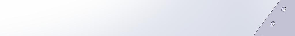
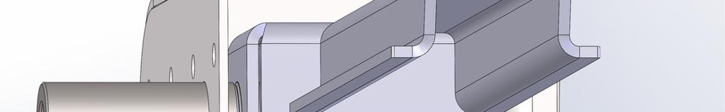
4 3. Install the rear frame rail sections. a. Do each frame rail modification one side at a time to avoid vehicle distortion. b. Remove original jounce bumpers and cut brackets off of rear frame rails. Grind frame rails smooth. c. Measure 29" and 12" from the front surface of rear leaf spring bushing sleeve and mark the frame rail at these locations. Mark the vertical cut lines perpendicular to the trunk pan. Mark the horizontal cut lines with a straight edge perpendicular to car centerline. Do not use a square off the original frame rail as it is not parallel with car centerline. (Figures 1 and 2) Figure 1 Figure 2 d. Hold the DSE frame rail section at these marked locations and reference the angled part of the DSE part to mark the angle cut line of the original frame rail. Cut out the original frame section at the marked locations. Drill spot welds to help remove any remaining upper frame rail material. Use a grinder to clean up and straighten the cut lines. (Figure 3) Figure 3 e. Remove paint from the areas the DSE frame rail section will attach. Fit the DSE frame rail section in place and clamp securely. The DSE rail section should be parallel with car centerline. Mark the top inside and outside edges of the DSE rail section. Mark the original frame rail bottom for a "pie cut" so it can be blended into the DSE rail section. (Figure 4) DSE-F (Rev 10/2/14) Page 4 of 21


. Figure 5 Figure 6 i.")
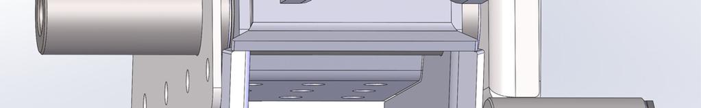
5 Figure 4 f. Remove the DSE frame rail section to make the "pie cut" in the original rail. At this time lay out and drill plug welding holes in the trunk pan using the rail outline drawn earlier. Apply etching primer to the surfaces that will be in-accessible after the DSE rail section is installed. g. Fit the DSE frame rail section back in place and clamp securely. Again make sure the rail section is parallel with car centerline. Align the bottom of the original frame rail that you "pie cut" to the DSE frame rail section and tack in place. After tack welding, stitch weld all remaining seams. Grind the welds smooth in preparation for doubler plates. h. Hold the doubler plates in position and mark, cut and bend lines as necessary. After cutting and bending the doubler plates layout and drill plug welding holes. Tack weld the doubler plates in position. Finish weld and plug weld each of the doubler plates and then finish grind the welds for a smooth, finished look. (Figures 5 and 6). Figure 5 Figure 6 i. From the inside of the trunk remove any paint around the plug welding holes. Plug weld trunk pan to the top of the DSE frame rail section and grind smooth. j. Repeat this process for the other side. 4. Install the upper cross-member. a. Cut the floor pan sheet metal horizontally 1-1/4" from the front fuel tank mounting flange between the DSE inner frame rail surfaces. DSE-F (Rev 10/2/14) Page 5 of 21
6 b. Cut the floor pan sheet metal along the rear spot weld flange of the original rear shock cross-member between the DSE inner frame rail surfaces. c. Trim the upper cross-member and set into position and plug weld the front and rear flanges to the original floor and trunk sheet metal. d. Use the provided templates to cut-out the front trunk corners for exhaust clearance. Fit and weld in the provided closeout corner pieces. This is a good time to mock-up and fit the DSE fuel tank. e. Make a flat piece out of 1/8" steel to close-out the upper cross-member to the inner frame rail face. (Figures 7-12) Figure 7 DSE-F (Rev 10/2/14) Page 6 of 21 Figure 8
7 Figure 9 Figure 10 DSE-F (Rev 10/2/14) Page 7 of 21
8 Figure 11 Figure 12 DSE-F (Rev 10/2/14) Page 8 of 21
9 5. Install the upper shock mounts. a. Measure between the inner frame rail surfaces to mark center on the Anti-Roll Bar (ARB) crossmember. b. Mark a vertical line 16-1/2" from each side of the cross-member centerline. c. Position the outboard surface of the upper shock mounts at these marks and tack in place. The side with the welded bushing faces outboard. Finish weld and plug weld each upper shock mount to the upper cross-member. (Figure 13) Figure Install the tubs. a. Install the DSE deep tubs as per the DSE deep tub kit instructions 7. Install the front upper link mounts. a. Use the provided template to mark the front upper link bolt hole locations with a center punch. b. Drill 1" hole at these locations using a hole saw. c. Slide the upper link bolt mounting crush tubes through these holes. Slide the outer closeout plate over the crush tubes and trim to fit as necessary. d. Fit the left and right upper link mounting brackets into place. Trim as necessary to fit nicely with the inner frame rail, floor pan, and original shock cross-member surfaces and tack in place. e. Measure the overall outer-outer frame rail width at the crush tube locations and record this number. Subtract 34.4 from this dimension and divide by 2. This calculated number is the distance the inboard end of the crush tube should be from each outer frame rail surface. Set each crush tube to this dimension and tack in place. f. Slide outer frame rail doubler over outboard side of crush tube and tack in place. g. Use provided 2.42" spacer to position inner closeout plate. Trim to fit as necessary and tack in place. h. Finish weld and plug weld both upper link mount assembles and remove 2.42" spacer. i. Trim the outer edge of the crush tube that extends past the outer frame rail leaving the weld. This will allow you more clearance for the bolt head between the frame rail and the inside flange of the deep tub when installing the upper link. j. Repeat this procedure for the other side. (Figures 14-16) DSE-F (Rev 10/2/14) Page 9 of 21
10 Figure 14 Figure 15 DSE-F (Rev 10/2/14) Page 10 of 21
11 Figure Install the torque boxes. a. Refer to the instructions provided in the torque box kit. 9. Install the front lower link mounts. NOTE: This section of the instructions has been updated since the installation DVD was created. a. Slide the 1 OD x 3.0 L crush tubes into the lower link mounts. Slide the lower link mount assemblies up into each torque box and install the 1/2-20 x 7.0 L bolts, washers and Nylock nuts and tighten. b. Make sure the top surface of the link mount seats flat on the bottom surface of the torque box. The link mounts should be approximately centered in the torque boxes and set the distance between each inner link mount surface to 29-5/16. Tack weld each lower link mount to the 1 OD crush tube. Remove and finish weld the crush tubes into the lower link mounts. c. Re-install the lower link mount assembly into the torque boxes and torque the 1/2-20 x 7.0 L bolts to 75 ft-lbs. Install a 2.42 long spacer in the center hole of each link mount assembly and final weld by plug welding the link mount assembly to the torque boxes and then perimeter weld. d. Cut and trim the front upper link mount braces as necessary to properly fit between the back lower link mount surfaces and the front surface of the upper link mounting bracket. (Figures 17-19). e. Remove the emergency brake cable brackets from each frame rail. DSE-F (Rev 10/2/14) Page 11 of 21


12 Figure 17 Figure 18 Figure 19 DSE-F (Rev 10/2/14) Page 12 of 21
13 10. Install the track bar body bracket. a. Position the track bar body bracket into place and tack. b. The top edges should sit on the DSE frame rail sections and trunk corner closeout. Use the extended lip at the top on the forward surface to set the bracket parallel with the ARB cross-member surface. With the vehicle level, the track bar bracket should be 90 (perpendicular) to the vehicle on both sides. Once correct location is verified finish weld. (Figure 20) Figure Install the axle brackets a. It is recommended that the axle brackets are installed when the axle tube flanges are not on the axle. If a new axle is being installed or the existing axle is being narrowed, install the axle brackets first, and then install the flanges. If the flanges are not removed, cut the axle brackets apart and weld them back together around the axle tube. b. It is important that the correct width for the bushings is maintained on the axle brackets when they are welded; therefore, the 2.42" spacers provided with the kit should be installed in the brackets in these areas during welding. Weld the axle bracket reinforcements on each bracket and position the axle brackets on the axle tubes. If you are cutting the axle bracket the reinforcements will be welded on after the axle bracket is in position and welded back together. Use the print in these instructions to locate the axle brackets on the rearend housing (See Figure 26). NOTE: Detroit Speed offers a pinion centering tool (P/N ) that will be helpful in placing your axle brackets in the correct location on your axle tube. c. Tack weld the brackets in place, and then verify that they are all positioned correctly. Weld the brackets securely in place. d. Install and weld the lower link/coilover reinforcement brackets as shown on Figure 26, if not done previously. e. The track bar axle bracket mounts outboard of the RH axle bracket as shown in Figure 26. Position the track bar axle bracket in place and tack weld. Verify the bracket fits tight to the axle bracket and around the axle tube and finish weld. f. Once all of the axle brackets are fully welded in place, remove the spacers, and check the axle for straightness. g. Position the ARB end-link brackets so that the 90 gusset mates up against the lower link/coilover bracket side surface. Clock the bracket so the end-link hole is centered on the axle tube. Use the included print to help set location. Tack each bracket in place and verify correct location before finish welding. DSE-F (Rev 10/2/14) Page 13 of 21
14 12. Verify the installation a. At this point the fabrication work is complete. Send the axle to a qualified shop to have the ends welded (if necessary). b. Check the axle tubes for straightness and have them straightened (if needed). c. Mocking up the car before painting all of the components is recommended. Mock up includes installing all of the suspension components (the link bolts still don t need to be tightened yet) installing the wheels/tires, and resting the vehicle on all four tires. d. Position the rear axle in place under the car and install the links. See the side view geometry diagram for information on link mounting positions. Nominal position for the track bar is bottom hole on the body mounting bracket. The track bar should be level at ride height. e. Support the axle at ride height. Check the axle position in the car and adjust the end links as necessary. Nominal ride height is 15" center-center on the shock mounting holes. f. Install the coilover shocks and springs so you can double check that the rear axle is positioned correctly in the vehicle. It should be centered from side to side, and the wheelbase should be correct on both sides of the vehicle (108.0 for a Mustang). The pinion angle should be measured and adjusted to your preference. 4 down is recommended. Raise and lower the vehicle to verify that there is no interference. Now is a good time to install the exhaust system. g. Paint or coat the components as desired. 13. Final assembly and adjustments a. It is easier to first install the ARB endlinks onto each axle bracket before the rearend is in the vehicle. Set the endlinks to 3.25" center-center and mount the female body end to the axle bracket. Torque the endlink stud nuts to 40 ft-lbs. Use provided super grease on the ARB bushings. Install the ARB onto ARB cross-member. Torque ARB mounting bolts to 30 ft-lbs with medium strength Loctite. Install the rear axle and suspension assembly; the end link bolts will be attached to the ARB later with the vehicle sitting at ride height. Install the link pivot bolts from the outboard side. The lower links will attach to the axle and body brackets using the provided 9/16-18 x 3-3/4 L hex head bolts, Nylock nuts, and SAE washers. The upper links will attach to the axle brackets using the provided 9/16-18 x 3-3/4 L hex head bolts, Nylock nuts, and SAE washers. The upper links will attach to the body brackets in the front using the provided 9/16-18 x 6-1/2 L hex head bolts, Nylock nuts, and washers. Do not torque the link pivot bolts at this time. Torque the coilover shock mounting bolts to 80 ft-lbs. b. Reinstall the fuel tank, fuel lines, and interior components that were removed. Install the wheels on the vehicle and lower it onto the ground. c. Verify that the track bar is installed in the hole that places it closest to horizontal (nominal design is lower hole]. d. Position the axle in the vehicle by adjusting the end links. NOTE: There can be no more than 2 of exposed threads on the end link (¾ of thread engagement in the tube). This measurement does not include the jam nut (see page 21). It should be centered from side to side, the wheelbase must be correct on both sides of the vehicle, and the pinion should be adjusted to the desired angle. Once the axle is in the proper position, torque the end link jam nuts to 100 ft-lbs. e. Settle the suspension by bouncing the vehicle several times. f. With the vehicle at ride height, torque the rear suspension link pivot bolts to 120 ft-lbs. g. Attached the ARB endlinks to the ARB and torque the endlink stud nuts to 40 ft-lbs. h. Confirm the axle position again. Double check that all of the bolts and jam nuts are tightened to their respective torque specifications. DSE-F (Rev 10/2/14) Page 14 of 21
15 Nominal Position Shown Instant Center: 48.5" Forward of Rear Axle Centerline 8.6" Above Ground Level **See chart below for adjustment info** Lower Link Adjustment Settings Axle Bracket Position Body Bracket Position Instant Center Notes Bottom Hole Top Hole 40.5" / 9.8" Frame must be modified Bottom Hole Middle Hole 48.5" / 8.6" DSE Nominal Setting Bottom Hole Bottom Hole 60.4" / 6.8" Middle Hole Top Hole 44.5" / 9.2" Middle Hole Middle Hole 55.8" / 7.5" Middle Hole Bottom Hole 75.0" / 4.6" Top Hole Top Hole 108.3" / -0.3" Top Hole Middle Hole 69.4" / 5.5" Top Hole Bottom Hole 51.0" / 8.2" Instant center numbers are expressed as distance forward of rear axle centerline, then height above ground level. DSE-F (Rev 10/2/14) Page 15 of 21
16 14. Setting the vehicle ride height. a. With the vehicle assembled with all components installed, adjust the ride height as necessary. Detroit Speed does recommend using a small wipe of anti-seize before adjusting the spanner nut and compressing the coilover spring. b. Detroit Speed does include a Spanner Tool (P/N: ) to adjust ride height however if you have the adjustable coilover shocks, Detroit Speed does offer an Adjustment Tool available as P/N: if needed. A photo can be seen in Figure 21. Figure 21 DSE Spanner & Adjustment tools 15. If the Single Adjustable, Double Adjustable or the Double Adjustable Remote Canister Coilovers were purchased as an upgrade, refer to the following information for adjustment procedures. PLEASE NOTE: ALL ADJUSTABLE TYPE SHOCKS GET MOUNTED BODY SIDE UP SHAFT SIDE DOWN DSE Single Adjustable Shock Applications To change from the recommended Detroit Tuned valving, adjustments can be made independently to the rebound setting. The rebound is controlled by the knob at the lower shock mount (Shock is mounted body side up). The knob rotates clockwise (+) to increase the damping and counterclockwise (-) to decrease the damping. Refer to Figure 22a below Rebound Knobs Figure 22a- DSE Single Adjustable Shock To return to the DSE recommended settings, turn the knob clockwise (+) to full damping. Once at full damping, turn counterclockwise (-) to reach the recommended settings. Refer to Figure 22b for the recommended starting setting. Rebound (Shaft Knob) 20 Open (counterclockwise, -) Figure 22b DSE Recommended Settings DSE-F (Rev 10/2/14) Page 16 of 21


 and referred to -0 (-0 = full stiff, -64 =")


17 Adjuster Operation Low-Speed Adjuster CLOSE - (Softer) + (Stiffer) Adjuster (60-64 Clicks) The low-speed adjuster is a clicker style adjuster meaning that its adjustment is measured by detents located inside the blue adjuster knob. There are 16 clicks per 1 revolution of the knob. It uses a right-hand thread in its operation which means as you increase low-speed, the adjuster will move up on the eyelet. The recommended change for an adjustment is 8 clicks at a time. The low-speed adjuster s reference position is full stiff (closed, or all the way up) and referred to -0 (-0 = full stiff, -64 = full soft). Tuning Notes o Racetrack o Street For more grip, soften the damping. For increased platform control, stiffen the damping. For a more comfortable ride, soften the damping *DO NOT FORCE KNOB WHEN IT STOPS TURNING, YOU MAY DAMAGE THE ADJUSTER AND INTERNAL HARDWARE DSE Double Adjustable Shock Applications To change from the recommended Detroit Tuned valving, adjustments can be made independently to both the high and low speed settings. The rebound is controlled by the sweepers at the lower shock mount. The sweepers rotate clockwise (+) to increase the damping and counterclockwise (-) to decrease the damping. The sweepers can be seen in Figure 23a. DSE-F (Rev 10/2/14) Page 17 of 21
 to full damping for the low speed setting, and counterclockwise (-) to full damping for the high speed setting.")
18 Sweepers Figure 23a DSE Double Adjustable Shock When adjusting the low speed rebound start at full (+) position, when adjusting the high speed rebound start at full (-) position. To return to the DSE recommended settings turn the sweeper clockwise(+) to full damping for the low speed setting, and counterclockwise (-) to full damping for the high speed setting. Once at full damping, turn counterclockwise(-) for the low speed setting, and clockwise(+) for the high speed setting to reach the recommended settings. Refer to Figure 23b for recommended starting settings. Low Speed Rebound (Sweeper) 20 sweeps (counterclockwise)(-) High Speed Rebound (Sweeper) 2 sweeps(clockwise)(+) Figure 23b DSE Recommended Settings DSE Double Adjustable Shocks w/remote Canisters To change from the recommended Detroit Tuned valving, adjustments can be made independently to both the high and low speed settings. The rebound is controlled by the sweepers at the lower shock mount. The sweepers rotate clockwise (+) to increase the damping and counterclockwise (-) to decrease the damping. Refer to Figure 24a. Charge Valve Sweepers Figure 24a DSE Double Adjustable Shock w/ Remote Canister When adjusting the low speed rebound start at full (+) position, when adjusting the high speed rebound start at full (-) position. To return to the DSE recommended settings turn the sweeper clockwise(+) to full damping for the low speed setting, and counterclockwise (-) to full damping for the high speed setting. Once at full damping, turn counterclockwise (-) for the low speed setting, and clockwise(+) for the high speed setting to reach the recommended settings. Refer to Figure 24b for recommended starting settings. Low Speed Rebound (Sweeper) 20 sweeps (counterclockwise)(-) High Speed Rebound (Sweeper) 2 sweeps(clockwise)(+) Figure 24b DSE Recommended Settings DSE-F (Rev 10/2/14) Page 18 of 21

.")
19 Adjuster Operation High-Speed Adjuster REBOUND Low-Speed Adjuster OPEN - (Softer) + (Stiffer) High-Speed Adjuster (12 Sweeps) The high-speed adjuster is a sweep style adjuster meaning that its adjustment is measured by the location of the adjuster in the eyelet window. It uses a left-hand thread in its operation which means; as you increase highspeed, the adjuster will move down in the window*. The high-speed adjuster s reference position is full soft and referred to as +0 (+0 = full soft, +12 = full stiff). Low-Speed Adjuster (25 Clicks) The low-speed adjuster is a clicker style adjuster meaning that its adjustment is measured by detent grooves located inside the high-speed shaft. It uses a right-hand thread in its operation which means; as you increase low-speed, the adjuster will move up in the window. The low-speed adjuster s reference position is full stiff and referred to -0 (-0 = full stiff, -25 = full soft). *The low-speed adjustment does not change when adjusting the high-speed. To aid in the installation of the reservoirs, we also offer a set of Billet Aluminum Remote Canister Mounts. The canister mounts are available exclusively through DSE, P/N: They are shown below in Figure 27. Figure 25 - Billet Aluminum Remote Canister Mounts Legal Disclaimer: Detroit Speed, Inc. is not liable for personal, property, legal, or financial damages from the use or misuse of any product we sell. The purchaser is solely responsible for the safety and performance of these products. No warranty is expressed or implied. DSE-F (Rev 10/2/14) Page 19 of 21
 662-3272.")
20 Figure 26 Once again, we appreciate your business. If you have any questions during the installation of this product, call (704) DSE-F (Rev 10/2/14) Page 20 of 21
21 Detroit Speed, Inc. Swivel-Links WARNING: There can be no more than 2 of exposed threads on the end link (3/4 of thread engagement in the tube). This measurement does not include the jam nut (see below). DSE-F (Rev 10/2/14) Page 21 of 21
Detroit Speed, Inc. QUADRA Link Rear Suspension Chevy II P/N:
 Detroit Speed, Inc. QUADRA Link Rear Suspension 1962-1967 Chevy II P/N: 041707 Detroit Speed, Inc. QUADRAlink is a great way to upgrade from original leaf spring suspension. Unlike our competitors, Detroit
Detroit Speed, Inc. QUADRA Link Rear Suspension Camaro/Firebird P/N:
 Detroit Speed, Inc. QUADRA Link Rear Suspension 1967-1969 Camaro/Firebird P/N: 041703 Figure 1 Item Component Quantity 1 Upper Link Front Pocket-Left 1 2 Upper Link Front Pocket-Right 1 3 Upper Shock Crossmember
Detroit Speed, Inc. QUADRA Link Rear Suspension Mustang P/N:
 Detroit Speed, Inc. QUADRA Link Rear Suspension 1964.5-1970 Mustang P/N: 041731 The Detroit Speed QUADRAlink is a great way to upgrade from an original leaf spring rear suspension. Detroit Speed's exclusive
Detroit Speed, Inc. QUADRA Link Rear Suspension Camaro/Firebird P/N:
 Detroit Speed, Inc. QUADRA Link Rear Suspension 1967-1969 Camaro/Firebird P/N: 041703 The Detroit Speed Inc., QUADRA Link rear suspension system is a great way to upgrade from an original leaf spring rear
Detroit Speed, Inc. QUADRA Link Rear Suspension Nova P/N:
 Detroit Speed, Inc. QUADRA Link Rear Suspension 1968-1974 Nova P/N: 041704 The Detroit Speed Inc., QUADRA Link rear suspension system is a great way to upgrade from an original leaf spring rear suspension.
Detroit Speed, Inc. Rear QUADRAlink Suspension Kit with 3 Axle Tube Camaro/Firebird P/N:
 Detroit Speed, Inc. Rear QUADRAlink Suspension Kit with 3 Axle Tube 1982-92 Camaro/Firebird P/N: 041722 The Detroit Speed Inc. QUADRAlink Kit, eliminates the factory torque arm configuration. It features
Detroit Speed, Inc. QUADRA Link Rear Suspension Camaro/Firebird P/N:
 Detroit Speed, Inc. QUADRA Link Rear Suspension 1970-1981 Camaro/Firebird P/N: 041711 INTRODUCTION Congratulations on your purchase of a QUADRA Link rear suspension from Detroit Speed and Engineering,
Detroit Speed, Inc Mustang Mini-Tubs P/N:
 Detroit Speed, Inc. 1964.5-1970 Mustang Mini-Tubs P/N: 040405 Item Component Quantity 1 DSE Mini-Tubs - Mustang 2 2 Frame Rail Sections 2 3 Doubler Plate 4" x 3.25" 4 4 Doubler Plate 4" x 2" 4 5 Installation
Detroit Speed, Inc. Rear QUADRAlink Conversion Kit Camaro/Firebird P/N:
 Detroit Speed, Inc. Rear QUADRAlink Conversion Kit 1982-92 Camaro/Firebird P/N: 041721 The Detroit Speed Inc. QUADRAlink Conversion Kit, eliminates the factory torque arm configuration. It features no-compromise
Detroit Speed, Inc. Mustang Mini-Tub Kit Mustang P/N:
 Detroit Speed, Inc. Mustang Mini-Tub Kit 1964.5-70 Mustang P/N: 040405 The Detroit Speed Mini-Tubs are inner wheel housings designed to accommodate wider wheel and tire package for the 1964½ - 1970 Mustang.
Detroit Speed, Inc. Mini-Tub Kit Chevy Nova, Oldsmobile Omega, Pontiac Ventura P/N: &
 Detroit Speed, Inc. Mini-Tub Kit 1968-74 Chevy Nova, Oldsmobile Omega, Pontiac Ventura P/N: 041207 & 041208 Item Component Quantity 1 DSE Mini Tubs 1968-74 X-Body 2 2 Rear Upper Shock Crossmember 1 3 Upper
Detroit Speed, Inc. Front Coilover Conversion GM A-body P/N: &
 Detroit Speed, Inc. Front Coilover Conversion 1964-67 GM A-body P/N: 030306 & 030307 The Detroit Speed, Inc. Front Coilover Conversion Kit is a direct bolt-in kit that provides excellent ride quality along
Detroit Speed, Inc. Subframe Connector Kit Mustang P/N #
 Detroit Speed, Inc. Subframe Connector Kit 1969-1970 Mustang P/N # 010108 Item Component Quantity 1 Subframe Connector 2 2 Front Frame Rail Doubler LH 1 3 Front Frame Rail Doubler RH 1 4 Front Frame Rail
Detroit Speed, Inc. Rear Coilover Kit Camaro P/N: , D
 Detroit Speed, Inc. Rear Coilover Kit 2010-15 Camaro P/N: 042430, 042430-D The Detroit Speed, Inc. 2010-15 Camaro rear coilover kit is a direct bolt-on assembly that completely replaces the OEM rear strut
Detroit Speed, Inc. Second Generation Camaro/Firebird Mini-Tub Kit Camaro/Firebird P/N: ,
 Detroit Speed, Inc. Second Generation Camaro/Firebird Mini-Tub Kit 1970-1981 Camaro/Firebird P/N: 041222, 041223 The Detroit Speed Second Generation Camaro/Firebird Rear Mini-Tub Kit is designed to accommodate
Detroit Speed, Inc. Front Coilover Conversion Camaro/Firebird, A-Body P/N: , , &
 Detroit Speed, Inc. Front Coilover Conversion 1970-81 Camaro/Firebird, 1968-72 A-Body P/N: 030308, 030309, 030313 & 030314 The Detroit Speed, Inc. Front Coilover Conversion Kit is a direct bolt-in kit
Detroit Speed, Inc. Front Coilover Conversion F-Body, X-Body, A-Body P/N: &
 Detroit Speed, Inc. Front Coilover Conversion 1967-69 F-Body, 1968-74 X-Body, 1968-72 A-Body P/N: 030311 & 030312 The Detroit Speed, Inc. Front Coilover Conversion Kit is a direct bolt-in kit that provides
Detroit Speed, Inc. Subframe Connector Kit Mustang P/N #
 Detroit Speed, Inc. Subframe Connector Kit 1964.5-1968 Mustang P/N # 010105 Item Component Quantity 1 Subframe Connector 2 2 Front Frame Rail Doubler LH 1 3 Front Frame Rail Doubler RH 1 4 Front Frame
Detroit Speed, Inc Chevy II Mini-Tubs P/N:
 Detroit Speed, Inc. 1962-67 Chevy II Mini-Tubs P/N: 040404 The Detroit Speed, Inc. Mini-Tubs are inner wheel housings designed to accommodate wider tire and wheel packages, including tires as wide as 295mm
Detroit Speed, Inc. Mini Tubs Camaro/Firebird P/N:
 Detroit Speed, Inc. Mini Tubs 1967-1969 Camaro/Firebird P/N: 040401 The Detroit Speed Mini-Tubs are inner wheel housings designed to accommodate a wider wheel and tire package. They are engineered for
Detroit Speed, Inc. ALUMA-Frame Front Suspension System Ford Mustang P/N:
 Detroit Speed, Inc. ALUMA-Frame Front Suspension System 1964.5-1970 Ford Mustang P/N: 032050 INTRODUCTION All aluminum front suspension system for 1964.5-1970 Mustangs featuring DSE s unique suspension
Detroit Speed, Inc. Front Coilover Kit Race Double Adjustable Camaro P/N:
 Detroit Speed, Inc. Front Coilover Kit Race Double Adjustable 2010+ Camaro P/N: 030321 Item Quantity Description 1 2 Front Strut Assembly (Double Adjustable) 2 2 Coilover Spring 250# x 2.5"ID x 8"L 3 2
Detroit Speed, Inc. Rear Tubular Anti-Roll Bar Kit F-Body & X-Body w/dse QUADRA Link P/N: , &
 Detroit Speed, Inc. Rear Tubular Anti-Roll Bar Kit 1967-1969 F-Body & 1968-74 X-Body w/dse QUADRA Link P/N: 042203, 042208 & 042217 The Detroit Speed, Inc. Rear Tubular Anti-roll Bar Kit is a great complement
Detroit Speed, Inc. Mini Tubs Camaro/Firebird P/N:
 Detroit Speed, Inc. Mini Tubs 1967-1969 Camaro/Firebird P/N: 040401 The Detroit Speed Mini-Tubs are inner wheel housings designed to accommodate a wider wheel and tire package. They are engineered for
Detroit Speed, Inc. C2/C3 SpeedRay Front Suspension Corvette P/N: &
 Detroit Speed, Inc. C2/C3 SpeedRay Front Suspension 1963-82 Corvette P/N: 032072 & 032073 The Detroit Speed Inc. Corvette SpeedRay front suspension improves handling and ride quality by utilizing Detroit
Detroit Speed, Inc. DSE/JRi Front Strut Kit Camaro/Firebird P/N: & D
 Detroit Speed, Inc. DSE/JRi Front Strut Kit 1982-92 Camaro/Firebird P/N: 030332 & 030332D The DSE/JRi Front Strut Kit is a high-performance aluminum body strut body with Detroit Tuned valving. The kit
Detroit Speed, Inc. Detroit Speed/JRi Front Strut Kit Camaro/Firebird P/N: & D
 Detroit Speed, Inc. Detroit Speed/JRi Front Strut Kit 1982-92 Camaro/Firebird P/N: 030332 & 030332D The Detroit Speed/JRi Front Strut Kit is a high-performance aluminum body strut body with Detroit Tuned
INTRODUCTION. DSE-F (11/17/2017) Page 1 of 22
 Page 1 of 22") Detroit Speed, Inc. Hydroformed Front Subframe 1967-1969 Camaro/Firebird & 1968-1974 Nova P/N: 032001, 032002, 032004, 032005, 032007, 032008, 032017, 032018, 032021 INTRODUCTION Congratulations on your
Detroit Speed, Inc. Hydroformed Front Subframe 1967-1969 Camaro/Firebird & 1968-1974 Nova P/N: 032001, 032002, 032004, 032005, 032007, 032008, 032017, 032018, 032021 INTRODUCTION Congratulations on your
Detroit Speed, Inc. Front Frame Chevy II P/N: through
 Detroit Speed, Inc. Front Frame 1962-1967 Chevy II P/N: 032031 through 032034 INTRODUCTION The Detroit Speed, Inc. front frame is a bolt-in replacement for the original stock frame. It improves handling
Detroit Speed, Inc. 4-Point Roll Cage Camaro/Firebird P/N:
 Detroit Speed, Inc. 4-Point Roll Cage 1970-1981 Camaro/Firebird P/N: 011303 Thank you for your purchase of the Detroit Speed 4-Point Roll Cage. The exclusive DSE design follows the interior lines of the
Detroit Speed, Inc. Front Coilover Kit Single Adjustable Camaro P/N:
 Detroit Speed, Inc. Front Coilover Kit Single Adjustable 2010-15 Camaro P/N: 030320 The Detroit Speed, Inc. 2010-15 Camaro Street Front Coilover Kit provides bolt-on replacement strut assemblies that are
Detroit Speed and Engineering Subframe Connector Camaro/Firebird P/N #
 Detroit Speed and Engineering Subframe Connector 1970-81 Camaro/Firebird P/N # 010103 1 2 5 3 4 Item Component Quantity 1 LH Subframe Connector 1 2 RH Subframe Connector 1 3 Inside Bracket 2 4 Outside
Part # GM F Body Rear R-Joint Bolt-in 4 Link GM F Body Rear Bolt-in 4Link. Table of contents. Installation Instructions
 Part # 11167199-1967-1969 GM F Body Rear R-Joint Bolt-in 4 Link Recommended Tools 1967-1969 GM F Body Rear Bolt-in 4Link Installation Table of contents Page 2-3... Included Components Page 4... Hardware
Detroit Speed, Inc. Subframe Connectors Camaro/Firebird P/N:
 Detroit Speed, Inc. Subframe Connectors 1967-1969 Camaro/Firebird P/N: 010101 The Detroit Speed Inc., Subframe Connectors are designed to give maximum longitudinal and torsional stiffness by integrating
Detroit Speed, Inc. Rear Coilover Tower Brace Kit Camaro P/N:
 Detroit Speed, Inc. Rear Coilover Tower Brace Kit 2016+ Camaro P/N: 042433 The Detroit Speed, Inc. 2016+ Camaro Rear Coilover Tower Brace Kit is a bolt-in design that increases overall vehicle stiffness.
Detroit Speed, Inc. Detroit Speed Control Arm and Spindle Kit A-Body P/N: &
 Detroit Speed, Inc. Detroit Speed Control Arm and Spindle Kit 1964-72 A-Body P/N: 030104 & 030105 The Detroit Speed A-Body front suspension kit is a bolt-on package that addresses the shortcomings of the
Part # Mustang Complete CoilOver Kit
 Front Components: Part # 12100109 67-70 Mustang Complete CoilOver Kit 1 12103509 Non Adjustable Front CoilOvers 1 12102899 Lower StrongArms 1 12103699 Upper StrongArms Rear Components: 1 12106509 Non Adjustable
Chrysler A-Body Tubular A-Arms Installation Instructions A-ARM INSTALLATION
 1967-1976 Dodge Demon 1112 67-72 Chrysler A-Body Tubular A-Arms Installation Instructions Thank you for your purchase of this Hotchkis Performance product. Your A-Arm set was designed with the performance
Part # Chevy Level 2 CoilOver Suspension Package Two Piece Frame
 350 S. St. Charles St. Jasper, In. 47546 Ph. 812.482.2932 Fax 812.634.6632 www.ridetech.com Part # 11030210 55-57 Chevy Level 2 CoilOver Suspension Package Two Piece Frame Front Components: 1 11013510
67 [ ] OR [ ] REAR BRACKETS BARS Shocks Includes: Includes: Includes: Includes:
![67 [ ] OR [ ] REAR BRACKETS BARS Shocks Includes: Includes: Includes: Includes:](/thumbs/76/73590788.jpg "67 [ ] OR [ ] REAR BRACKETS BARS Shocks Includes: Includes: Includes: Includes:") 1967-1969 Firebird Mini Tub 4-Link Install Instructions 1-866-925-1101 www.totalcostinvolved.com CHECK ALL PARTS INCLUDED IN THIS KIT TO THE PARTS LIST BEFORE INSTALLATING OF THE KIT. IF ANY PIECES ARE
1967-1969 Firebird Mini Tub 4-Link Install Instructions 1-866-925-1101 www.totalcostinvolved.com CHECK ALL PARTS INCLUDED IN THIS KIT TO THE PARTS LIST BEFORE INSTALLATING OF THE KIT. IF ANY PIECES ARE
Part # GM F Body Complete CoilOver System
 350 S. St. Charles St. Jasper, In. 47546 Ph. 812.482.2932 Fax 812.634.6632 www.ridetech.com Part # 11170109 70-81 GM F Body Complete CoilOver System Front Components: 1 11173509 Front Fixed Valving CoilOvers
Part # Mustang Complete SA CoilOver Kit
 Front Components: 350 S. St. Charles St. Jasper, In. 47546 Ph. 812.482.2932 Fax 812.634.6632 www.ridetech.com Part # 12100210 67-70 Mustang Complete SA CoilOver Kit 1 12103510 Single Adjustable Front CoilOvers
Part # Mustang Complete CoilOver Kit
 Front Components: 1 12103509 Front CoilOvers 1 12102899 Lower StrongArms 1 12103699 Upper StrongArms 350 S. St. Charles St. Jasper, In. 47546 Ph. 812.482.2932 Fax 812.634.6632 www.ridetech.com Part # 12100109
GM B-Body Street Grip
 Part # 11015010/11015110-1955-1957 GM B-Body StreetGrip Front Components 11019590 Delrin Control Arm Bushings 90003041 Tall Upper Balljoint 11012350/11012351 Front Dual Rate CoilSprings 22159847 Front
INSTALLATION INSTRUCTIONS 64 ½ - 70 SUPERRIDE II INDEPENDENT FRONT SUSPENSION BX-350 FOR COYOTE AND MOD ENGINES
 INSTALLATION INSTRUCTIONS 64 ½ - 70 SUPERRIDE II INDEPENDENT FRONT SUSPENSION BX-350 FOR COYOTE AND MOD ENGINES Please read these instructions completely before starting your installation. Assemble suspension
Detroit Speed, Inc. Selecta-Speed Wiper Kit Mustang P/N:
 Detroit Speed, Inc. Selecta-Speed Wiper Kit 1967-68 Mustang P/N: 121651 A downpour of rain will no longer hinder your ability to clearly see the road. The Detroit Speed Inc. Selecta-Speed Wiper Kit provides
INSTRUCTION G-Comp Unser Edition Rear Suspension: Chevy Nova. Kit Contents:
 INSTRUCTION 350-400 G-Comp Unser Edition Rear Suspension: 62-67 Chevy Nova Speedway Motors, Inc. 2017 Kit Contents: 350003.1 G-Comp Chassis Brace 350003.2 G-Comp Front Support 350400.1 Chevy II Unser Rear
HEIDTS RF-110. INSTALLATION INSTRUCTIONS Fairlane Comet Rear 4-Link
 HEIDTS RF-110 INSTALLATION INSTRUCTIONS 66-67 Fairlane 66-67 Comet Rear 4-Link Please read these instructions completely before starting your installation. Remember the basic rule for a successful installation:
Technical Support Line: (952) Hanover Ave. Lakeville, MN
 Hanover Ave. Lakeville, MN") Technical Support Line: (952) 985-5675 Email: Sales@QA1.net 21730 Hanover Ave. Lakeville, MN 55044 www.qa1.net INSTALLATION INSTRUCTIONS QA1 1967-1979 Mopar A-Body Rear 6 link Conversion System QA1 p/n
Technical Support Line: (952) 985-5675 Email: Sales@QA1.net 21730 Hanover Ave. Lakeville, MN 55044 www.qa1.net INSTALLATION INSTRUCTIONS QA1 1967-1979 Mopar A-Body Rear 6 link Conversion System QA1 p/n
Part # Galaxie Air Suspension System
 350 S. St. Charles St. Jasper, In. 47546 Ph. 812.482.2932 Fax 812.634.6632 www.ridetech.com Part # 12160298 60-64 Galaxie Air Suspension System Front Components: 1 12162401 Master Series Single Adjustable
Part # Chevy Level 2 Air Suspension Package One Piece Frame
 350 S. St. Charles St. Jasper, In. 47546 Ph. 812.482.2932 Fax 812.634.6632 www.ridetech.com Part # 11020299 55-57 Chevy Level 2 Air Suspension Package One Piece Frame Front Components: 1 11013001 Master
*NOTE* The following suspension system will not work with heavy duty axle housings as pictured below.
 1964 ½ - 1970 Ford Mustang Triangulated 4-Link Suspension Installation Instructions Tech Line: 1-855-693-1259 www.totalcostinvolved.com Read and understand these instructions before starting any work!
Installation Instructions
 Part # 12087199-1965-1970 Mustang Rear Bolt-in 4 Link Recommended Tools 1965-1970 Mustang Rear Bolt-in 4 Link Installation Table of contents Page 2... Included components Page 3... Hardware List and Getting
INSTALLATION INSTRUCTIONS CHEVROLET NOVA (NVR-301) INDEPENDENT REAR SUSPENSION
 INDEPENDENT REAR SUSPENSION") INSTALLATION INSTRUCTIONS 68-74 CHEVROLET NOVA (NVR-301) INDEPENDENT REAR SUSPENSION Please read these instructions completely before starting your installation. Assemble suspension on vehicle before powder-coating
INSTALLATION INSTRUCTIONS 68-74 CHEVROLET NOVA (NVR-301) INDEPENDENT REAR SUSPENSION Please read these instructions completely before starting your installation. Assemble suspension on vehicle before powder-coating
SYNERGY SUSPENSION UNIVERSAL FRONT 3-LINK KIT Version 1.0
 5051 - SYNERGY SUSPENSION UNIVERSAL FRONT 3-LINK KIT Version 1.0 GENERAL NOTES: These instructions are also available on our website; www.synergymfg.com. Check the website before you begin for any updated
Detroit Speed, Inc. Selecta-Speed Wiper Kit Corvette P/N:
 Detroit Speed, Inc. Selecta-Speed Wiper Kit 1968-72 Corvette P/N: 121621 A downpour of rain will no longer hinder your ability to clearly see the road. The Detroit Speed Selecta-Speed Wiper Kit provides
Master Your Terrain (307)
") Master Your Terrain (307) 775 9565 www.tntcustoms.com Y-Link Extreme Duty Long Arm Coil Conversion Jeep Cherokee Installation Instructions Congratulations for purchasing a TNT, INC. Extreme Duty Y-Link
Master Your Terrain (307) 775 9565 www.tntcustoms.com Y-Link Extreme Duty Long Arm Coil Conversion Jeep Cherokee Installation Instructions Congratulations for purchasing a TNT, INC. Extreme Duty Y-Link
Chevrolet 3100 IFS Kit
 1947-54 Chevrolet 3100 IFS Kit Congratulations on your purchase on what we believe is the finest IFS kit available for 1947-54 Chevrolet pickups with stock frames. We have invested many hours into designing
Installation instructions for non, single & double adjustable hydraulic ride height system
 Installation instructions for non, single & double adjustable hydraulic ride height system *Single adjustable shocks shown **Springs sold separately ***Only adjustable shocks include reservoirs Table of
EVO-1050 JK Long Arm Upgrade w/ EVOlever
 EVO-1050 JK Long Arm Upgrade w/ EVOlever Recommended: All Vehicles that spend time on salted roads. It is recommended that removal of both threaded collar and joint on all arms. Apply a small amount of
1203AA GM A-BODY Double Adjustable Trailing Arms
 1203AA 64-67 GM A-BODY Double Adjustable Trailing Arms Warning: This installation should be performed by a trained professional. Note, pictures in this booklet are from a 77-96 GM B Body. Installation
QA1 MOD Series Shock Installation and Quick Tuning Guide
 QA1 MOD Series Shock Installation and Quick Tuning Guide 9919-237 Rev. 10092018 Introduction Congratulations on your purchase of QA1 s double adjustable MOD Series shocks with low-speed bleed adjustment!
Mustang. MOD1 Coilover Kit FXXADK0100, FXXADK0200, FXXADK0400 FXXA1K0100, FXXA1K0200, FXXA1K0400
 1964.5-1973 Mustang MOD1 Coilover Kit FXXADK0100, FXXADK0200, FXXADK0400 FXXA1K0100, FXXA1K0200, FXXA1K0400 2276 Research Dr. Livermore, Ca 94550 Ph: (925)-443-6300 E: maier@mikemaierinc.com Page 1 of
Chevrolet Bar Kit
 1947-53 Chevrolet 3100 4-Bar Kit Congratulations on your purchase on what we believe is the finest rear suspension 4-bar kit available for 1947-53 Chevrolet pickups with stock frames. We have invested
Detroit Speed, Inc. Electric Headlight Door Kit Corvette P/N: &
 Detroit Speed, Inc. Electric Headlight Door Kit 1968-82 Corvette P/N: 122006 & 122007 The Detroit Speed Inc. Electric Headlight Door Kit replaces the stock vacuum actuated system on all 1968-82 Corvettes.
Part # Cougar CoilOver System
 Front Components: 1 12103510 HQ Series Front CoilOvers 1 12102899 Lower StrongArms 1 12103699 Upper StrongArms 1 12109100 Front MuscleBar w/ PosiLinks 350 S. St. Charles St. Jasper, In. 47546 Ph. 812.482.2932
Street-Lynx By. Reilly MotorSports, Inc. Installation Manual
 Street-Lynx By Reilly MotorSports, Inc. Installation Manual 1 1- Begin by removing your original rear suspension disconnect your brake lines, E-brake cables, and remove the driveshaft. To prevent fire
C5/C6 Level 3 Coilover
 Part # 11510311-1998-2013 C5/C6 Level 3 CoilOver System Front Components: 11513111 Front Coilovers Recommended Tools Rear Components: 11516111 Rear Coilover Miscellaneous Components: 85000000 Spanner Wrench
Detroit Speed, Inc. Selecta-Speed Wiper Kit Corvette P/N:
 Detroit Speed, Inc. Selecta-Speed Wiper Kit 1963-67 Corvette P/N: 121620 A downpour of rain will no longer hinder your ability to clearly see the road. The Detroit Speed Selecta-Speed Wiper Kit provides
DODGE SuperRail Mounting Kit #0848
 DODGE SuperRail Mounting Kit #0848 #1200 Super 5 th (16K) #0800 Super 5 th (20.5K) Gross Trailer Weight (Maximum) Vertical Load Weight (Max. Pin Weight) 16,000 lbs. 4,000 lbs. Gross Trailer Weight (Maximum)
Camaro Torque Arm Install Instructions
 1967-1969 Camaro Torque Arm Install Instructions 1-800-984-6259 www.totalcostinvolved.com 67 [429-4202-00] OR 68-69 [429-4202-00] REAR BRACKETS BARS Shocks Includes: Includes: Includes: Includes: 1 REAR
TAS002 TORQUE ARM CONVERSION INSTALLATION INSTRUCTIONS Camaro and Firebird Ford 9
 TAS002 TORQUE ARM CONVERSION INSTALLATION INSTRUCTIONS 1967-1969 Camaro and Firebird Ford 9 Please take note before proceeding with this installation: This product may interfere with certain exhaust kits.
USE THE PARTS LIST BELOW TO MAKE SURE YOUR KIT IS COMPLETE BEFORE INSTALLATION. IF ANY PIECES ARE MISSING, PLEASE CONTACT:
 60-65 Ford Falcon Triangulated 4-Link Suspension Installation Instructions Tech Line: 1-855-693-1259 www.totalcostinvolved.com Read and understand these instructions before starting any work! USE THE PARTS
73-87 C-10 Coilover System
 Part # 11360201-73-87 C10 CoilOver System Front Components: 11362699 Front StrongArm System 11369300 Front Spindles and Caliper Brackets 11363510 Front Coilovers 11369100 Front MuscleBar Recommended Tools
CHECK ALL PARTS INCLUDED IN THIS KIT TO THE PARTS LIST BEFORE INSTALLATION. IF ANY PIECES ARE MISSING, PLEASE CONTACT: TOTAL COST INVOLVED
 1949-1954 TCI Engineering Chevy Rear 4-Link Coil-Over & Air Bag Kit Installation Instructions 1-866-925-1101 www.totalcostinvolved.com Read and understand these instructions before starting any work! CHECK
Detroit Speed, Inc. Caster/Camber Plate Kit Camaro/Firebird P/N:
 Detroit Speed, Inc. Caster/Camber Plate Kit 1982-92 Camaro/Firebird P/N: 030330 The Detroit Speed Inc., Caster/Camber Plate Kit is a direct bolt-on kit that allows precise camber and caster adjustments
Installation Instructions Camaro Level 2 Coilover. Part # Camaro Level 2 CoilOver System.
 Part # 00-99-00 Camaro Level CoilOver System Front Components: 0 Front CoilOver Strut Recommended Tools Rear Components: 60 Rear Coilover Miscellaneous Components: 85000000 Spanner Wrench 99-00 Camaro
INSTALLATION GUIDE F20 g-link Billet Canted 4-Bar Air-Spring Rear Frame and Suspension Camaro & Firebird
 READ ALL INSTRUCTIONS COMPLETELY AND THOROUGHLY UNDERSTAND THEM BEFORE DOING ANYTHING. CALL CHASSISWORKS TECH SUPPORT (916) 388-0288 IF YOU NEED ASSISTANCE. INSTALLATION GUIDE 5843-F20 g-link Billet Canted
INSTALLATION INSTRUCTIONS Progress Technology Rear Anti-Sway Bar Honda Civic Part # No Revision (7/20/16)
") INSTALLATION INSTRUCTIONS Progress Technology Rear Anti-Sway Bar Honda Civic 96-00 Part # 62.1042 No Revision (7/20/16) WHO SHOULD INSTALL THIS PRODUCT? Progress Technology products should only be installed
INSTALLATION INSTRUCTIONS Progress Technology Rear Anti-Sway Bar Honda Civic 96-00 Part # 62.1042 No Revision (7/20/16) WHO SHOULD INSTALL THIS PRODUCT? Progress Technology products should only be installed
INSTALLATION GUIDE X10 AirLink Canted 4-Bar Rear Air Suspension Chevy II
 READ ALL INSTRUCTIONS COMPLETELY AND THOROUGHLY UNDERSTAND THEM BEFORE DOING ANYTHING. CALL CHASSISWORKS TECH SUPPORT (916) 388-0288 IF YOU NEED ASSISTANCE. INSTALLATION GUIDE 5805-X10 AirLink Canted 4-Bar
Sport Sway Bar Kit Mustang
 Sport Sway Bar Kit 22102 2005 Mustang Installation of Hotchkis Front Sway Bar 1F Raising Vehicle Securely block the rear wheels of the vehicle. Use a jack to lift up the front of the vehicle and use jack
INSTALLATION GUIDE Bolt-On Drag-Race Strut Clip Chevy II
 INSTALLATION GUIDE 7702 Bolt-On Drag-Race Strut Clip 1962-67 Chevy II Description: STRUT CLIP 4130 BOLT ON 62-67 CHEVY II, INCLUDES 4130 ROUND TUBE FRAME CLIP, DOUBLE-ADJUSTABLE STRUTS, ADJUSTABLE-HEIGHT
INSTALLATION INSTRUCTIONS P/N: C2005 LADDER LINK
 INSTALLATION INSTRUCTIONS P/N: C2005 LADDER LINK The Competition Engineering Ladder Link offers all the strength of our standard ladder bar coupled with an adjustable pivoting lower link that enables you
Detroit Speed, Inc. Rear Cradle Mounts Camaro P/N:
 Detroit Speed, Inc. Rear Cradle Mounts 2010-15 Camaro P/N: 041510 Replace the weak, compliant factory rear cradle mounts in your 2010-15 Camaro with Detroit Speed s Solid Rear Cradle Mounts, and completely
Detroit Speed, Inc. Detroit Speed C7 Rear Full Floater Kit P/N: , , , , &
 Detroit Speed, Inc. Detroit Speed C7 Rear Full Floater Kit P/N: 070512, 070607, 070616, 070626, 070636 & 070649 Thank you for purchasing the Detroit Speed Inc., C7 Rear Full Floater Kit. The Detroit Speed
Chevy Nova Pro-Touring Front Suspension Installation Instructions
 1962-1967 Chevy Nova Pro-Touring Front Suspension Installation Instructions 1-800-984-6259 www.totalcostinvolved.com 1 Pro-Touring Clip A-Arm Assembly Sway Bar Assembly Fender Panel Kit 8 7/16-20 * 1 ¼
Part # Chevy Level 3 Street Challenge Package Two Piece Frame
 350 S. St. Charles St. Jasper, In. 47546 Ph. 812.482.2932 Fax 812.634.6632 www.ridetech.com Part # 11030399 55-57 Chevy Level 3 Street Challenge Package Two Piece Frame Front Components: 1 11013002 Master
For Technical Assistance, call Competition Engineering's Tech Line at (203) , 8:30am-5:00pm Eastern Time COMPETITION ENGINEERING
 , 8:30am-5:00pm Eastern Time COMPETITION ENGINEERING") INSTALLATION INSTRUCTIONS C2099 SLIDE-A-LINK The Slide-A-Link by Competition Engineering is designed for use in Stock Eliminator and Bracket Racing vehicles. The rigid front mount assembly clamps around
INSTALLATION INSTRUCTIONS C2099 SLIDE-A-LINK The Slide-A-Link by Competition Engineering is designed for use in Stock Eliminator and Bracket Racing vehicles. The rigid front mount assembly clamps around
INSTALLATION INSTRUCTIONS QA1 P/N R , R , R R , R , R F100 Rear Coil-over Conversion System
 INSTALLATION INSTRUCTIONS QA1 P/N R120-170, R120-200, R120-250 R220-170, R220-200, R220-250 65-72 F100 Rear Coil-over Conversion System TOOLS AND SUPPLIES REQUIRED Floor Jack Two (2) Jack Stands Drill
INSTALLATION INSTRUCTIONS P/N: C2006 LADDER BAR
 INSTALLATION INSTRUCTIONS P/N: C2006 LADDER BAR PARTS LIST 2) Ladder Bars 4) Lg. Housing Brackets 4) RH Solid Rod Ends 6) RH Jam Nuts 2) Spherical Rod Ends 4) Washers 6) 3/4"-16 x 2-1/2" Bolts 6) 3/4"-16
# C5/C6
 Part # 00-998-0 C/C Level CoilOver System Front Components: 0 Front Coilovers Recommended Tools Rear Components: 0 Rear Coilover Miscellaneous Components: 8000000 Spanner Wrench 998-0 C/C Level Coilover
MM Rear Coil-Over Kit - Koni Single and Double Adjustable Shocks (MMCO-5)
") 3430 Sacramento Dr., Unit D San Luis Obispo, CA 93401 Telephone: 805/544-8748 Fax: 805/544-8645 www.maximummotorsports.com MM Rear Coil-Over Kit - Koni Single and Double Adjustable Shocks (MMCO-5) Read
3430 Sacramento Dr., Unit D San Luis Obispo, CA 93401 Telephone: 805/544-8748 Fax: 805/544-8645 www.maximummotorsports.com MM Rear Coil-Over Kit - Koni Single and Double Adjustable Shocks (MMCO-5) Read
C5/C6 Level 2 Coilover
 Part # 5020-998-203 C5/C6 Level 2 CoilOver System Front Components: 530 Front Coilovers Recommended Tools Rear Components: 560 Rear Coilover Miscellaneous Components: 85000000 Spanner Wrench 998-203 C5/C6
INSTRUCTIONS. 4-Link Parallel With Adjustable Panhard Bar Rear Suspension System FOR MOPAR MUSCLE CARS: A-BODY (RS-5435)
") MOPAR A-BODY 4-LINK PARALLEL COIL OVER SYSTEM INSTRUCTIONS 4-Link Parallel With Adjustable Panhard Bar Rear Suspension System FOR MOPAR MUSCLE CARS: 1967-1976 A-BODY (RS-5435) Revised: 6-1-2011 Page 2
MOPAR A-BODY 4-LINK PARALLEL COIL OVER SYSTEM INSTRUCTIONS 4-Link Parallel With Adjustable Panhard Bar Rear Suspension System FOR MOPAR MUSCLE CARS: 1967-1976 A-BODY (RS-5435) Revised: 6-1-2011 Page 2
USE THE PARTS LIST BELOW TO MAKE SURE YOUR KIT IS COMPLETE BEFORE INSTALLATION. IF ANY PIECES ARE MISSING, PLEASE CONTACT:
 1962-1967 Chevy Nova Pro-Touring Front Suspension Installation Instructions Tech line: 1-855-693-1259 www.totalcostinvolved.com Read and understand these instructions before starting any work! USE THE
INSTRUCTION G-Comp Rear Suspension: Chevy Camaro. Kit Contents:
 INSTRUCTION 350-700 G-Comp Rear Suspension: 70-81 Chevy Camaro Speedway Motors, Inc. 2017 Kit Contents: 350700.1 G-Comp Crossmember & Chassis Brace 350700.2 G-Comp Rear Crossmember Assembly 350700.3 G-Comp
Next, chase the threads in the lower A-arm mounts with the 5/8-18 tap and blowout any remaining particles.
 Next, chase the threads in the lower A-arm mounts with the 5/8-18 tap and blowout any remaining particles. Now, apply some anti-seize to the threads of the pivot stud. Also put anti-seize inside the bore
INSTALLATION INSTRUCTIONS P/N S: C2091 & C2093 SLIDE-A-LINK
 INSTALLATION INSTRUCTIONS P/N S: C2091 & C2093 SLIDE-A-LINK The Slide-A-Link by Competition Engineering is designed for use in Stock Eliminator and Bracket Racing vehicles. The rigid front mount assembly
Part # Chevy Level 3 Street Challenge Package One Piece Frame
 350 S. St. Charles St. Jasper, In. 47546 Ph. 812.482.2932 Fax 812.634.6632 www.ridetech.com Part # 11020399 55-57 Chevy Level 3 Street Challenge Package One Piece Frame Front Components: 1 11013011 TQ
COMPETITION ENGINEERING. 80 Carter Drive P.O. Box 1470 Guilford, CT Phone: (203) Fax: (203)
 Fax: (203)") INSTALLATION INSTRUCTIONS P/N S: C2090 & C2092 SLIDE-A-LINK The Slide-A-Link by Competition Engineering is designed for use in Stock Eliminator and Bracket Racing vehicles. The rigid front mount assembly
INSTALLATION INSTRUCTIONS P/N S: C2090 & C2092 SLIDE-A-LINK The Slide-A-Link by Competition Engineering is designed for use in Stock Eliminator and Bracket Racing vehicles. The rigid front mount assembly