Supra-Blast Cartridge Dust Collector Installation and Operation Manual
|
|
|
- Martha Tucker
- 5 years ago
- Views:
Transcription

1 Installation and Operation Manual
2
3 TABLE OF CONTENTS Page 1. IMPORTANT NOTICE General Cautions INTRODUCTION Unit Nomenclature Description and Operation Air Filtering Operation Filter Cleaning Cycle SPECIFICATION TABLE INSTALLATION Off Loading and Inspection Installation Planning Assembly of Standard Equipment Electrical Installation Compressed Air Connection Assembly of Optional Equipment OPERATION Start-Up Checklist Checking the Pulse Cleaning System with Your Controller Operating Adjustments SERVICE Cartridge Filter Removal and Replacement Cartridge Filter Seeding Procedures Dust Removal Servicing the Compressed Air Components Servicing the Direct Drive Blower and Motor System Servicing Optional Return Air Safety Filters (HEPA/ASHRAE) Supra-Max Series Cartridge Filters TROUBLESHOOTING GUIDE ILLUSTRATED PARTS Series Bill of Materials i
4
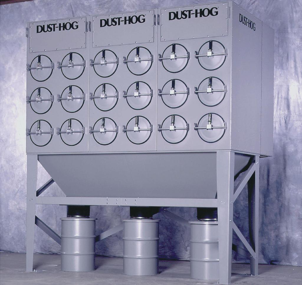
5 1. IMPORTANT NOTICE This manual contains important safety information and precautionary measures. It is impossible to list all potential hazards associated with every dust collection system in each application. Proper use of the equipment must be discussed with United Air Specialists, Inc. (UAS) or your local DUST-HOG representative. Operating personnel must be aware of, and adhere to, the most stringent safety procedures.! WARNING A warning symbol means people may be injured if the procedures are not followed. A caution symbol is used when equipment could be damaged if the procedures are not followed. 1.1 GENERAL CAUTIONS 1. Avoid mixing combustible materials such as aluminum, paper, wood or other organic dusts with dusts generated from grinding metals. A fire hazard could develop from sparks entering the dust collector. When collecting flammable or explosive materials, the dust collector should be located outdoors and incorporate the appropriate safety measures and/or accessories. 2. When collecting emissions from spark-producing processes, care must be taken to reduce any potential fire hazards. System design should include methods to prevent sparks from entering the dust collector. Dust collectors do not contain fire extinguishing equipment unless specifically ordered. Experts in the field of fire extinguishing equipment should be consulted for recommendations concerning proper fire detection and suppression systems. 3. Some dust collection systems require explosion venting. Consult your insurance underwriter, NFPA (National Fire Protection Association) Manual and your local fire authorities to determine the requirements for explosion venting. 4. Be careful and conscientious consult national and local fire codes, waste disposal, safety and other appropriate authorities. Comply with their recommendations for the proper installation and operation of dust collection equipment. 2. INTRODUCTION Thank you for selecting DUST-HOG dust collection equipment to assist you in your commitment to a clean and safe environment. We trust that in purchasing our product you have recognized our commitment to continually offer dust collection equipment engineered to each dust collection need and manufactured to the highest standards. If at any time you have a question about dust collection, please do not hesitate to call your local DUST-HOG representative or the nearest UAS customer service office listed on the back cover of this manual. The DUST-HOG product line offers stateof-the-art cleaning power and dust collection capacity. Designed to collect process-generated dusts, is the first centralized cartridge dust collector with UAS exclusive air distribution insert within the cartridge filter and QuickSeal filter access doors. The dust collector shall not be used for any purpose not listed in this manual. As you review this manual, refer to Figure 1 for assistance in identifying dust collector parts. The Specification Table in Section 3 provides additional unit information. 2.1 UNIT NOMENCLATURE The product line is separated into two models. SBS designates a single-filter configuration unit and SBD designates a double-filter configuration unit. EXAMPLE: SBS 4-2-H55 SBS DUST-HOG single-filter configuration unit 4 number of cartridge filters (2,4,6 or 8) 2 number of filter tiers H55 unit base arrangement H55 - hopper with 44" (112 cm) clearance for standard 55 gallon (208 liter) drum SD - hopper with 26" (66 cm) clearance for UAS-supplied 30 gallon (114 liter) drum OB - open bottom construction BV - custom bin vent unit with open bottom United Air Specialists, Inc. 1
6 EXAMPLE: SBD 24-3-H55 SBD DUST-HOG double-filter configuration unit 24 number of cartridge filters 3 number of filter tiers H55 unit base arrangement H55 - hopper with 44" (112 cm) clearance for standard 55 gallon (208 liter) drum SD - hopper with 26" (66 cm) clearance for UAS-supplied 30 gallon (114 liter) drum OB - open bottom construction 2.2 DESCRIPTION AND OPERATION The DUST-HOG is a high-efficiency, cartridge dust collector designed to eliminate airborne dust as it is generated. Contaminants are captured at the source(s), then conveyed through ductwork to the cartridge filter section (dirty air section) where the dust is collected. Clean air is then discharged from the unit through the clean air discharge. The dust collector is designed for on-line or downtime cartridge filter cleaning by means of a customersupplied compressed air system. The is a high-efficiency, horizontallyoriented cartridge dust collector equipped with 15" (38 cm) outside diameter cartridge filters. The larger diameter Supra-Max Series cartridge filter design allows for lower pressure losses through the dust collector while increasing the amount of media contained in each filter. DUST-HOG Series dust collectors have pre-engineered backward-inclined or radial-type optional blower packages in 3, 5, 7 1 /2, 10, 15, 20, 25 and 30 HP (2.2, 3.7, 5.5, 7.5, 11, 15, 18.5 and 22 kw) assemblies. There are two primary modes of operation the air filtering operation and filter cleaning cycle. Both modes of operation are shown in Figure AIR FILTERING OPERATION The contaminated airstream is drawn into the dust collector where its velocity is reduced by inlet baffle plates to provide even air distribution across the entire surface area of the cartridge filters. This design enhances filtration efficiency by establishing a uniform dust cake on the filters. The airstream is then directed around the cartridge filters and down toward the hopper where the heavier particles discharge to the dust storage drum. The contaminated air then passes through the cartridge filters. The filter media strips the dust from the airstream allowing only clean air to pass through the cartridge filter. The air then passes into the clean air plenum, through a blower package and is discharged from the unit. 2.4 FILTER CLEANING CYCLE During normal operation, the surface of the cartridge filters become loaded with contaminants. The reverse pulse cleaning mechanism provides brief bursts of compressed air, directed through the diaphragm valves, toward an air distribution tip and into the center of the cartridge filter. This pulsing action dislodges the collected particles from the media where they fall into the hopper and are discharged to the dust storage drum. During the cleaning cycle, each row of cartridge filters is cleaned individually. The solid-state sequential timer actuates a solenoid valve, which allows an air diaphragm valve to open for approximately 100 milliseconds. High-pressure air from the air manifold reservoir is directed through the diaphragm valve toward the air distribution tip mounted on the tubesheet in front of the cartridge filter. The air is then directed into the cartridge filter. The filter s air distribution insert maximizes the compressed air energy to increase the amount of collected dust released from the filter surface. The dislodged dust removed from the filter is swept downward into the hopper. The remaining filters are cleaned sequentially. The sequencing is factory preset at 10-second intervals and is adjustable to adapt to your particular cleaning needs. 2 United Air Specialists, Inc.
7 Figure 1. Air Filter Operation & Cleaning United Air Specialists, Inc. 3
8 3. SPECIFICATION TABLE Model Filter Quantity Total Supra-Netmax Filter Media Area (FT 2 ) (M 2 ) Valve Quantity Module Quantity Unit Weight (LBS) (KGS) SBS H , SBS H55 4 1, , SBS H55 6 1, ,554 1,158 SBS H55 8 2, ,090 1,402 SBD H55 8 2, ,363 1,072 SBD H , ,909 1,773 SBD H , ,533 2,510 SBD H , ,282 3,303 SBD H , ,824 1,281 SBD H , ,687 2,126 SBD H ,160 1, ,628 3,006 SBD H ,880 1, ,694 3,944 SBD H ,600 1, ,635 4,824 SBD H ,320 2, ,576 5,704 SBD H , ,313 1,503 SBD H , ,521 2,504 SBD H ,880 1, ,807 3,541 SBD H ,840 1, ,218 4,635 SBD H ,800 2, ,504 5,672 SBD H ,760 2, ,790 6,709 SBD H ,720 3, ,201 7,802 SBD H ,680 3, ,487 8, INSTALLATION 4.1 OFF LOADING AND INSPECTION dust collector modules are shipped assembled on a skid(s). Other skids will contain the hopper/leg assembly and other components. Other accessories (afterfilter assemblies, blower packages, dust storage drums, silencers, etc.) may be on additional, separate skids. Lift the dust collector components by the packing skids or use the external lifting lugs provided on the filter module. Do not lift the filter module of the dust collector by placing lift truck forks through the cartridge filter access doors. The filter support rails or the conical air distribution tips installed on the tubesheet could be damaged. Upon receipt of your unit, check for any shipping damage. A damaged carton indicates that the equipment may have received rough handling during shipping that may have caused internal damage. Notify your delivery carrier and enter a claim if any damage is found. 4.2 INSTALLATION PLANNING The proper location of your dust collection equipment is very important. Refer to Figures 2 and 3 for typical installation details. Certain items should be considered when locating the unit, such as emptying of the dust storage drum(s), filter removal requirements, compressed air connections, access to the clean air plenum, electrical connections, blower location and discharge direction. The shortest duct length with a minimum number of elbows will maximize the performance of the unit. Ease of maintenance should also be considered when selecting the location and orientation of the system. Refer to Figure 4 for recommended unit clearances. 4 United Air Specialists, Inc.
9 Figure 2. SBS Typical Installation Diagram , REV A United Air Specialists, Inc. 5
10 Figure 3. SBD Typical Installation Diagram , REV A 6 United Air Specialists, Inc.
11 Figure 4. Recommended Unit Clearances United Air Specialists, Inc. 7
12 In the case of spark producing processes, system design should incorporate measures to prevent live sparks from entering the dust collector. Consult local authorities for the location of this unit and any additional precautions to consider when collecting combustible, explosive or hazardous dusts. General warnings and cautions are provided in Section 1.1. The dust collector should be mounted on a solid, level, reinforced concrete foundation. Other mounting options are also possible. Structural calculations for the foundation or other mounting arrangements must include the weight of the collected material and the weight of all auxiliary equipment installed with the dust collector (ductwork, abrasive inlet, blower package, afterfilter assembly, etc.). The Specification Table in Section 3 provides unit weights. These weights must be considered together with wind loading, seismic loading and other live load ratings when designing the dust collector foundation support structure. Consult a professional engineer when designing the foundation for the unit. Interconnecting ductwork should be designed to include a volume control damper for regulating system design airflow. United Air Specialists, Inc. offers optional volume control dampers which can be installed on the air inlet/ outlet ductwork of the unit to regulate airflow. Ductwork must be properly sized to meet the recommended air velocities for the material being collected. Follow ductwork design methods as listed in the Industrial Ventilation Manual as recommended by the American Conference of Governmental Industrial Hygienists. 4.3 ASSEMBLY OF STANDARD EQUIPMENT Use adequate safety measures when lifting and assembling any heavy components. Consult your plant safety personnel for recommendations. Remove all crating, strapping and hold-down bolts. Locate all hardware bags, sealant and other assembly materials provided with your unit. HOPPER ASSEMBLIES The series filter module is designed to mount directly on top of the hopper assembly. A hopper assembly consists of a hopper bin, legs, side diagonal sway braces, rear diagonal sway braces, front horizontal brace and hardware installation kit. Most hopper bins will be factory assembled with the legs and sway bracing. Some hopper assemblies may be shipped in pieces and will need to be assembled at the site. If the hopper assembly is factory assembled, position hopper and legs on the mounting pad. Shim legs as required and secure leg assemblies to concrete mounting pad with appropriate anchoring hardware. Anchors should be provided by customer or contractor according to local codes. If the hopper sections are shipped in pieces for field assembly, position legs as shown in Plan Detail on the unit sales drawing. Bolt on sway braces using hardware as shown in Figures 5 and 6. Leave all hardware handtight; shim legs as required. Extend hopper leg alignment bolts through leg upper surface (refer to Figure 7, View G). Fit hopper over leg assemblies, positioning the corner holes of the hopper over the alignment bolts in each leg gusset corner (refer to Figure 7, View H). Secure leg assemblies to concrete mounting pad with appropriate anchoring hardware. Anchors should be provided by customer or contractor according to local codes. FULLY-ASSEMBLED FILTER MODULE SECTIONS Apply two ribbons of sealant to hopper flange to create figure 8 pattern around mounting holes (refer to Figure 7, View H). In preparing to attach the filter module to the hopper, connect lifting slings and spreader bars to all filter module lifting lugs with clevis pins. Use spreader bars to distribute the load evenly. Location must be clear of all obstructions, such as utility lines or roof overhangs. Place filter module onto hopper/leg assemblies, positioning filter module corner holes over alignment pins in leg gussets (refer to Figure 8, Detail K). Drift pins will also be useful for locating the filter module section onto the hopper. 8 United Air Specialists, Inc.
13 Figure 5. Leg Assembly Details FIELD_INSTALL_DWG1/ SUPRABLAST/SALES/ FIELD_INSTALL_DRW/ SHEET 1 United Air Specialists, Inc. 9
14 Figure 6. Leg Brace Assembly Details FIELD_INSTALL_DWG1/ SUPRABLAST/SALES/ FIELD_INSTALL_DRW/ SHEET 2 10 United Air Specialists, Inc.
15 NOTE: Each hopper assembly is equipped with four 1 /2" (13 mm) pry locations two holes on front flange and two holes on rear flange. Refer to Figure 8, Detail K, to aid in aligning the hopper flange with the module flange. With filter module still supported, use hardware (refer to Figure 8, Section P-P) to bolt the hopper and filter module together. Securely tighten all hardware at the filter module and hopper. Recheck leg assembly sway braces to ensure they are tight. Install fasteners (bolt, flat washer, lock-washer, nut) to all four pry locations. Disconnect lifting slings and spreader bars used for installation. MULTIPLE, BOLT-TOGETHER MODULE SECTIONS For units that have multiple, bolt-together module sections, remove the row of filters from the modules nearest the bolting flange (refer to Section 6.1). Protect the doors and filters removed by placing in a safe area away from work area. Identify the different module sections. There are left (bolt flange on the right side), right (bolt flange on the left side) and possibly center (bolt flanges on both sides) module sections. Install all hopper/leg assemblies as previously described. With multiple hoppers, the leg assemblies should be bolted together (refer to Figure 5, Section F-F). Apply two ribbons of sealant to only the first hopper flange to create figure 8 pattern around mounting holes (refer to Figure 7, View H). In preparing to attach the filter module to the hopper, connect lifting slings and spreader bars to all filter module lifting lugs with clevis pins. Distribute the load evenly. Location must be clear of all obstructions, such as utility lines or roof overhangs. Place the appropriate filter module onto the hopper/leg assembly to which the sealant has been applied, positioning filter module corner holes over alignment pins in leg gussets (refer to Figure 8, Detail K). Drift pins will also be useful for locating the module section onto the hopper. NOTE: Each hopper assembly is equipped with four 1 /2" (13 mm) pry locations two holes on front flange and two holes on rear flange. Refer to Figure 8, Detail K, to aid in aligning the hopper flange with the module flange. United Air Specialists, Inc. With the filter module still supported, use hardware (refer to Figure 8, Section P-P) to bolt the hopper and filter module together. Securely tighten all hardware at the filter module and hopper. Recheck leg assembly sway braces to ensure they are tight. Install fasteners (bolt, flat washer, lock-washer, nut) to all four pry locations. Disconnect lifting slings and spreader bars used for installation. Apply sealant to the next hopper to receive a filter module (refer to Figure 7, View H). Apply sealant to the side bolting flange of the next filter module to be installed using the figure 8 pattern (refer to Figure 9, Detail J). Place this module on its hopper. Use the hardware provided (refer to Figure 9, Detail L) and bolt the module sections together. Bolt the filter module to the hopper (refer to Figure 8, Section P-P). Securely tighten all hardware at the filter module and hopper. Recheck leg assembly sway braces to ensure they are tight. Install fasteners (bolt, flat washer, lock-washer, nut) to all four pry locations. Disconnect the lifting slings and spreader bars used for installation. Repeat this process until all the module sections are in place, securely fastened and anchored to the foundation. Recheck all hardware connections to make certain they are securely tightened. Remove lift slings and spreader bars and clear all tools from the work area. NOTE: Make certain all bolts (including the anchor bolts) are properly tightened before proceeding with the remainder of the installation. Install all cartridge filters removed at the beginning of the installation process and install the filter access doors (refer to Section 6.1). CLEAN AIR SECTION BOTTOM ACCESS PANEL INSTALLATION The bottom access panel and its gasket are shipped loose with installation hardware. If the bottom access will not be used for discharge ductwork, attach the panel to the bottom opening using the hardware provided. For top-mount blower packages of 20 HP (15 kw) or larger, an additional set of support legs is provided. The additional support legs must be mounted under the filter module supporting the blower package (refer to Figure 10). Bolt the mounting plate to the bottom of the appropriate clean air plenum with the hardware provided. Bolt the leg assemblies to the mounting plate 11
16 with the hardware provided. Secure leg assemblies to the concrete mounting pad with appropriate anchoring hardware. 4.4 ELECTRICAL INSTALLATION All electrical work should be performed by a qualified electrician in accordance with local electrical codes. Disconnect electrical power before installing or servicing any electrical component. GENERAL Several types of standard electrical components can be installed to control and monitor your dust collector ensuring proper cleaning of the cartridge filters. A fan motor starter circuit is required to start and stop the system. The motor starter circuit should consist of a properly-sized, fused disconnect or circuit breaker, contactor and overload relay for short circuit and overload protection of the blower package. A 115/1/60 low voltage (2 amp) control circuit is required for the pulse cleaning controls. Any one of the following control configurations can be used (refer to Figures for wiring schematics): Motor starter with Supra-Clean timerboard for continuous pulse (Magnehelic Guage). Refer to Figure 11 for recommended wiring. Motor starter with Supra-Clean timerboard for setpoint pulse (Photohelic Guages). Refer to Figure 11 for recommended wiring. Motor starter with Supra-View Panel for self-contained differential pressure display, pulse control and alarm. Refer to Figure 12 for recommended wiring. Motor starter with Supra-I.Q. Diagnostics Panel for complete monitoring and automated pulse control. Refer to Figure 13 for recommended wiring. Refer to UAS sales order to verify the control configuration purchased with your unit MOUNTING OF THE CONTROLS Mount the motor starter for the fan motor control in a convenient location. The motor starter is provided by the customer, unless specifically ordered from UAS. Mounting hardware for a UAS starter panel is provided by the customer or contractor. Mount the solid-state cleaning controls (Supra-Clean, Supra-View or Supra-I.Q.) in a convenient location. It is recommended that the controls be mounted on a wall or pedestal in a convenient area subject to minimal vibration and electrical noise. Avoid mounting the Supra-Clean, Supra-View or Supra-I.Q. Panel on the collector due to vibration generated from blower assembly and the pulsing system PULSE CLEANING CONTROLS For a more in-depth explanation of the cleaning control features and options, refer to Section 5 or the Installation and Operation Manual supplied with the Supra-Clean timerboard, Supra-View Panel or Supra-I.Q. Diagnostics Panel SOLENOID VALVE ENCLOSURE WIRING The solenoid valves at the dust collector must be wired correctly to the pulse controls. Refer to Figure 14 when making connections from the pulse controls (Supra- Clean timerboard, Supra-View Panel or Supra-I.Q. Diagnostics Panel) to the solenoid valve enclosure(s). Example: Figure 14 shows the SBD-XX-4 having eight valve locations per module. This means when the system pulses, 1 is the first pulse in the sequence, 2 is the second, 3 is the third, etc. When multiple dust collector modules are installed, daisy chain the wiring so that each solenoid valve with the same module location will pulse at the same time. This means all #1 solenoid valves are tied together and wired to pulse controller OUT 1, #2 solenoid valves are tied together and wired to pulse controller OUT 2, etc. Refer to Figure 14 for the dust collector solenoid valve wiring information. When cleaning, the pulse valves sequence left to right, top to bottom. Unless specified on the UAS sales order, the customer will supply interconnecting material (conduit, wiring, etc.) from the pulse controls to the dust collector HEATER WIRING In cold or damp environments, the heater serves to prevent the electric solenoid valves from freezing due to cold temperatures or condensation. If optional solenoid valve heater is purchased, each solenoid valve enclosure will contain a 100-WATT cartridge heater internally prewired to a thermostat. The customer must supply a separate, VAC, 50-60Hz, 1 amp supply power to the heater circuit for each module. The supply must be available to the module solenoid valve enclosure(s) at all time (even when the blower is shut down) to ensure temperature regulation inside each solenoid valve enclosure is continual. When 12 United Air Specialists, Inc.
17 FIELD_INSTALL_DWG1/SUPRABLAST/SALES/FIELD_INSTALL_DRW/SHEET 3 Figure 7. Hopper Assembly Details United Air Specialists, Inc. 13
18 Figure 8. Module to Hopper Assembly Details FIELD_INSTALL_DWG1/SUPRABLAST/SALES/FIELD_INSTALL_DRW/SHEET 4 14 United Air Specialists, Inc.
19 FIELD_INSTALL_DWG1/SUPRABLAST/SALES/FIELD_INSTALL_DRW/SHEET 5 Figure 9. Multiple Filter Module Section Assembly Details United Air Specialists, Inc. 15
20 Figure 10. Top-Mount Blower Support Leg Assembly United Air Specialists, Inc.
21 Figure 11. Power and Elementary Wiring for Units with Supra-Clean Timerboard and Magnehelic/Photohelic Control , REV E United Air Specialists, Inc. 17
22 Figure 12. Power and Elementary Wiring for Units with Supra-View Panel United Air Specialists, Inc.
23 Figure 13. Power and Elementary Wiring for Units with Supra-I.Q. Diagnostics Panel , REV D United Air Specialists, Inc. 19
24 Figure 14. Solenoid Wiring to Pulse Controls , REV C 20 United Air Specialists, Inc.
25 multiple module solenoid valve enclosures with heaters are installed, daisy chain the wiring so that each heater will have 100/115/VAC, 50/60 Hz at all times. Make certain enough current is available to supply all heaters. Example: If three solenoid valve enclosures are supplied with cartridge heaters, make certain the voltage supply can deliver 3 amps (1 amp per heater). 4.5 COMPRESSED AIR CONNECTION Do not allow water and/or oil from the compressed air system into the compressed air manifold reservoir. To ensure a clean, dry air supply, especially when the unit is installed outdoors, a water filter with automatic drain (or a condensate trap with automatic drain) and a coalescing filter should be installed (refer to Figure 15). Clean, dry, PSIG ( BAR) compressed air is required for the pulse cleaning system to function properly. Compressed air consumption is noted on the UAS sales drawing. A shut-off valve, pressure regulator and pressure gauge should be installed close to the unit. UAS recommends dedicated oil and water removal filters be used to ensure clean, dry air is delivered to the pulse system. Contact your local DUST- HOG representative for information about UAS s Pneumatic Valve Assembly. Refer to Figure 15 for recommended compressed air piping and Table 1 below for proper compressed air line sizing. Using Table 1, select the proper diameter compressed air line pipe to supply your dust collector. The final connection size is a female 1" NPT fitting on each module. Pipe Diameter Number of Distance of Supply Air Filter Section or Piping Run From Modules Main Compressor Line 1 inch (25 mm) feet (15 meters) 1 1 /2 inch (38 mm) feet (31 meters) 2 inch (51 mm) feet (+31 meters) Table 1 Pipe Diameter Selection Purge the compressed air line to remove any debris prior to making the final connection to the compressed air manifold(s). Apply pipe fitting sealant on all compressed air supply piping fittings and connections. 4.6 ASSEMBLY OF OPTIONAL EQUIPMENT BLOWER PACKAGE INSTALLATION Anchor dust collector to concrete pad prior to installing blower assembly. Make certain all hardware is properly tightened. If a top-mount blower package was ordered, read the manufacturer s Installation and Operation Manual completely before installing the blower. The blower Installation and Operation Manual is attached to the fan package. Perform all pre-installation checks prior to installing the blower. If blower package has a 20 HP (15 kw) motor or larger, ensure the blower support legs are installed beneath the clean air plenum of the module to which the blower will be mounted. Remove the clean air plenum cover plate on top of the filter module and save the mounting hardware. Ensure ribbon gasket remains on the unit. Lift blower package using safe, suitable means and position blower base holes over filter module holes with blower discharge pointing in the desired direction. Secure with bolt/ washer assemblies previously removed. Top-mount blower packages include a blower outlet damper. Install blower damper to outlet of blower assembly with hardware provided. If the blower package is a ground-mount blower, read the manufacturer s Installation and Operation Manual completely before installing the blower. The blower Installation and Operation Manual is attached to the fan package. Perform all pre-installation checks prior to installing the blower. Outlet duckwork from the unit to the blower package can be connected to either the top or bottom clean air section access panel(s). It is recommended industry practice to provide vibration isolation between the blower inlet and the dust collector outlet ducting. DUCT SILENCER INSTALLATION A duct-type (in-line) silencer is designed to bolt directly to the blower outlet damper flange. Make certain there is adequate room for the silencer in the discharge direction. Provide at least 24" (61 cm) of unobstructed space at the end of the silencer discharge. The air discharge should be directed into an open area, free of obstructions and with consideration for personnel safety. United Air Specialists, Inc. 21
26 Figure 15. Pneumatic Valve Assembly United Air Specialists, Inc.
27 Figure 16. Abrasive Inlet Installation United Air Specialists, Inc. 23
28 The silencer will require a separate support. Do not use the blower damper or outlet flange to support the silencer. Apply silicone around the bolt holes of the connecting flanges, lift the silencer into position and secure with the hardware provided. Install permanent supports (customer-supplied) and tighten all hardware before removing the lifting device. ROTARY AIR LOCK INSTALLATION If a rotary air lock was ordered with the unit, the hopper discharge will have an adapter already bolted to it. Make certain the bolts connecting the adapter to the hopper discharge are securely tightened. Remove all packing from the rotary air lock and determine its appropriate position. Keep in mind required clearances, electrical connections and maintenance. Apply sealant to the flange of the rotary air lock and fasten to the adapter using M10 bolts, washers and lock washers. All electrical connections shall be made by a qualified electrician according to all applicable codes. Refer to the nameplate and/or documentation for voltage, amperage, cycle and proper wiring. Refer to rotary air lock vendor documentation attached with air lock device. Remove the front access panel(s) located above the QuickSeal filter access doors. Save the hardware. The hardware will be used to attach the abrasive inlet. Remove any remaining gasket material from around the perimeter of the opening. Apply a 1/4" (6 mm) bead of sealant around the perimeter of the access opening in a figure 8 pattern around the bolt holes. Align the hole pattern on the abrasive inlet with the hole pattern on the unit and bolt together using the hardware removed earlier. Fasten the inlet ductwork securely to the abrasive inlet assembly. The bottom plate of the abrasive inlet will serve as an inspection plate. If access to the abrasive inlet is required, remove and clean out the bottom plate of the inlet prior to servicing. Do not damage the ribbon of gasket and reuse after cleaning the gasket surfaces. DRUM LID INSTALLATION The drum lid package is an optional accessory for series dust collectors. Remove the drum lid package from its shipping carton. Place the drum lid on the 55-gallon (208 liter) drum (H55) or 30-gallon (114 liter) short drum (SD). Slide the 14" (360 mm) diameter hose over the drum lid and secure with a hose clamp. Position the drum assembly under the unit, slide the hose up onto the discharge adapter collar on the hopper and secure with a hose clamp. Disconnect all power to the rotary air lock before servicing. There are moving parts on the rotary air lock. Do not allow any object to be placed in or near the rotary air lock during operation. Verify rotary air lock rotation matches rotation arrows affixed to assembly. ABRASIVE INLET INSTALLATION The abrasive inlet is designed to use the front access panel(s) of the series modules as the inlet area to the unit. There are two styles available - a single or dual module abrasive inlet. Each is designed to fit over the appropriate number of front access panels to serve as a single inlet point for one or two modules (refer to Figure 16) Figure 17. Drum Lid Installation 24 United Air Specialists, Inc.
29 If a drum lid latch kit was ordered, attach the separate clamp band around the 55-gallon (208 liter) drum or 30-gallon (114 liter) short drum, leaving the cinch bolt loose. Position the three latch pawls onto the drum lid catches, rotating the drum lid as required. Tighten the cinch bolt and adjust the latch tension or band placement as required (refer to Figure 17). The Photohelic Guage and mounting bracket should be installed within sight of the as shown in Figure 18. Hardware to mount the bracket to the support structure is not supplied by UAS. The Photohelic Guage requires electrical connections. Refer to Figure 11 for details. If a slide gate was ordered, it was factory installed on the hopper. Open the slide gate. Repeat for multiple drum lid connections. NOTE: Make certain to install the two jumper wires (customer-supplied) as shown in the instruction manual provided with the gauge. NOTE: The hopper(s) is not designed for dust storage. The slide gate should remain open during normal operation. INLET COLLAR AND BLANK COVER PLATE INSTALLATION Inlet collar and blank cover plates bolt directly to the unit. Inlet and outlet collar assemblies are specified with initial order. If inlet diameters or locations are not specified with initial order, the dust collector is supplied with all blank cover plates. MAGNEHELIC GUAGE INSTALLATION If your system was ordered with a Magnehelic Guage, remove it and the hardware from the box. Instructions for mounting and connecting the Magnehelic Guage are provided by the manufacturer. Follow these instructions using the hardware provided. The gauge should be installed within sight of the unit as shown in Figure 18. NOTE: The hardware provided is designed for surface mounting of the Magnehelic Guage. Make certain to install the 1/8" NPT pipe plugs in the pressure ports on the back of the gauge.! WARNING Failure to install 1/8" NPT pipe plugs in pressure ports on the rear of the Magnehelic Guage will cause the gauge to read incorrectly. Install the tube fittings in the pressure ports on the side of the gauge. Mount it to the bracket, and the bracket to a support structure. PHOTOHELIC GUAGE INSTALLATION If your system was ordered with a Photohelic Guage, remove it and the hardware from the box. Instructions for mounting and connecting the Photohelic Guage are provided by the manufacturer. Follow these instructions using the hardware and UAS mounting bracket provided. United Air Specialists, Inc. Refer to the manufacturer s instructions for outdoor installation. FINAL CONNECTIONS FOR ALL GAUGE OPTIONS For any control system, connect the black, plastic pressure tubing (25 feet [7.5 meters] provide by UAS) to the gauge or panel fittings and the unit. Connect the dirty air plenum of the to the high pressure port on the gauge or panel as shown in Figure 18. Connect the clean air plenum of the Supra- Blast to the low pressure port on the gauge or panel as shown in Figure 18. Zero, calibrate and maintain the gauge as recommended by the manufacturer. NOTE: Gauge should be installed within 50 feet (15 meters) of the dust collector. SUPRA-CLEAN TIMERBOARD INSTALLATION Please refer to the Supra-Clean Installation and Operation Manual for proper installation details. SUPRA-VIEW PANEL INSTALLATION Please refer to the Supra-View Installation and Operation Manual for proper installation details. SUPRA-I.Q. DIAGNOSTICS PANEL INSTALLATION If your system was ordered with a Supra-I.Q. Diagnostics Panel, please refer to the Supra-I.Q. Installation and Operation Manual for proper installation details. REMOTE BLOWER START/STOP ASSEMBLY A remote blower start/stop pushbutton station is available for field installation on assemblies that have been configured with a combination magnetic motor/ blower starter control package supplied by UAS. The combination magnetic motor/blower starter control package must be configured and wired in accordance with Figure 11, 12 or 13. The customer is required to 25
30 Figure 18. Typical Pressure Gauge Installation , REV A 26 United Air Specialists, Inc.
31 supply interconnecting signal cord and mounting hardware for remote blower start/stop assembly installation. Remove jumper between terminals L and 20 in the combination magnetic motor/blower starter control package as shown in Figure 11, 12 or OPERATION Shut off unit disconnect and lock out all electrical power to the dust collector prior to performing service work. Prior to unit start-up, all installation set-up instructions must be completed as specified by this manual, the Supra-Clean Installation and Operation Manual, Supra-View Installation and Operation Manual, Supra- I.Q. Installation and Operation Manual, as well as any manuals supplied by other equipment manufacturers, as they apply to your dust collector. 5.1 START-UP Inspect the installation area and make certain no tools, parts, etc., have been left anywhere on or inside the unit. Check blower discharge to make certain it is free from all debris. Start motor/blower and check for proper rotation. A rotation arrow is located on the blower housing. All topmount blower assemblies rotate in a clockwise rotation as viewed from the driven end (motor end with motor cooling fan). If the blower is rotating in the opposite direction, disconnect the power to the motor starter. For 3-phase blowers, interchange any two power wires to the motor at the load side of the motor starter contactor. For singlephase power, refer to motor nameplate for which two wires to interchange at motor junction box. Engage starter disconnect, start blower and recheck rotation. NOTE: Proper blower rotation is required to move the designed amount of air. A blower rotating in the incorrect direction will only move about 40% of design airflow. The blower assembly provided by United Air Specialists, Inc. includes an outlet damper. If the blower assembly was purchased separately, ensure a volume control damper is included somewhere in the dust collection system. Close the blower discharge damper to the 50% open position and tighten in place. If a volume control damper is provided in another part of the dust collection system, adjust second damper to the 50% open position and tighten in place. United Air Specialists, Inc. NOTE: It is important that the air volume of the dust collection system is at design conditions at system start-up. There is a minimal pressure differential across new cartridge filters. If the volume control damper is not correctly adjusted, the air volume will be above design conditions for airflow and may affect the cartridge filter life. Verify dust collector system airflow is adjusted to design conditions with a new, clean filter using the volume control dampers installed in the system. Failure to properly adjust system airflow may affect cartridge filter life. The air volume should be adjusted based on the performance of the entire system. Air volume control damper adjusted to the system design conditions. Closing the volume control damper decreases system airflow. Opening the volume control damper increases system airflow. On certain applications, it may be beneficial to seed or pre-coat the original or replacement cartridge filters. This process introduces a certain amount of coating particulate (usually crushed limestone, agricultural lime or other specifically marketed pre-coat) in light concentration to deposit a thin coating of material which acts as an aid to filtration. This deposited dust cake keeps the dust loading on the surface of the cartridge filter. This process will increase filter life and efficiency while allowing the cleaning system to operate more effectively. For filter seeding procedures, refer to Section 6.2. Turn on the compressed air supply to the dust collector air manifold reservoir. Adjust the pressure regulator until the gauge reads PSIG ( BAR). 5.2 CHECKLIST Check the discharge of the blower assembly. Initially, some dust may discharge from the blower assembly as the filters are seasoned. This may last several minutes after which the discharge air should remain visibly clean. Measure the total airflow and static pressure at the inlet to the unit. Adjust the blower outlet damper for the desired airflow. Check to ensure that adequate air is being drawn into each of the collection points of the system. Adjust the individual dampers for each operation to balance the system airflow. Recheck the total system airflow and adjust the blower damper to desired system airflow. This procedure may need to be repeated several times until the entire system is within system design airflow specifications. 27
32 Check the differential pressure reading across the dust collector clean to dirty air sections. A normal differential pressure drop reading is between 1"-6" w.g. ( mmaq). At start-up, this reading is generally in the 1"-3" w.g. (25-76 mmaq) range. Please list the reading here for future reference. Initial dust collector differential pressure reading across filters is " w.g. or (mmaq) on (date). NOTE: If your system is controlled by the Supra-I.Q. Diagnostics Panel, the yellow airflow alert light may be illuminated. This is normal unitl the Air Flow Calibration routine has been performed at the Supra-I.Q. Diagnostics Panel. This must be performed during start-up of your dust collection system once all of the inlet(s) and ductwork is in place and the outlet damper (if required) is opened 75%. Refer to the Supra- I.Q. Installation and Operation Manual and perform the Code 4 - Airflow Settings steps. 5.3 CHECKING THE PULSE CLEANING SYSTEM WITH YOUR CONTROLLER Check the cleaning system for proper operation. The compressed air pressure should be between PSIG ( BAR). The Supra-Clean, Supra-View and Supra-I.Q. panels are factory set to pulse every 10 seconds. Refer to the Supra-Clean, Supra-View or Supra-I.Q. Installation and Operation Manual to change these initial settings. Check to ensure the pulse (diaphragm) valves are firing at approximately 10- second intervals and deliver a crisp sounding pulse to each filter. The valves should not deliver a weak or lingering pulse. To check the pulse sequence for proper firing, perform the following: If your system is supplied with a Supra-Clean timerboard (with Magnehelic or Photohelic Guage) or Supra-View Panel, place the Continuous Clean/PS switch on the timerboard to the Continuous Clean position. The MOT AUX terminals at the timerboard must have continuity for the pulsing to become active. To activate, energize the motor starter to close the isolated auxiliary contact wired to the timerboard MOT AUX terminals. Verify robust and consistent pulse firing of each valve. If your system is supplied with a Supra-I.Q. Diagnostics Panel, place the system in Continuous Clean by entering Code 5. At the SET MODE state, enter 1 for continuous cleaning. Terminals 1 and 2 at terminal strip P7 must have continuity for the cleaning system to activate. Allow 45 seconds after panel power-up for pulsing to start as the Supra-I.Q. cleaning mode(s) operate on a delay. Verify robust and consistent pulse firing of each valve. When test is complete, enter code 5. At the SET MODE state, enter 2 for Auto-tune cleaning mode. 5.4 OPERATING ADJUSTMENTS Please confirm the type of pulse cleaning controller delivered with your system. Your system was delivered with one of the following: Magnehelic Guage with Supra-Clean timerboard Photohelic Guage with Supra-Clean timerboard Supra-View Pulse Panel Supra-I.Q. Diagnostics Panel NOTE: It is important that the compressed air pressure in the manifold is above 90 PSIG immediately prior to a pulse. If the delivery capability of your compressed air source cannot return the manifold pressure to above 90 PSIG during the Pulse Delay (time between pulses) interval, adjust the pulse delay at the timerboard or Supra-I.Q. and monitor the pressure. A longer interval will raise the operating pressure and a shorter interval will lower the operating pressure. Allow sufficient time for the system to stabilize after each adjustment before making any further adjustment. Adjust until the desired manifold pressure is reached. MAGNEHELIC GUAGE CONTROL WITH SUPRA-CLEAN TIMERBOARD When using a Magnehelic Guage with Supra-Clean timerboard, the timerboard is always set to Continuous Clean pulse mode. If the filters are operating at a higher or lower pressure than desired, adjusting the pulse frequency (Pulse Delay) can often modify the steadystate pressure. The factory setting is 10-second intervals. Adjust the Pulse Delay on the Supra-Clean timerboard and monitor the pressure on the Magnehelic Guage. A longer interval will raise the operating pressure and a short interval will lower the operating pressure. Allow sufficient time for the system to stabilize after each adjustment before making any further adjustment. Adjust until the desired manifold pressure is reached. 28 United Air Specialists, Inc.
33 PHOTOHELIC GUAGE CONTROL WITH SUPRA-CLEAN TIMERBOARD When using a Photohelic Guage with Supra-Clean timerboard, the timerboard is set to PS pulse mode (pulse cleaning activated by the Photohelic control) or Continuous Clean pulse mode to override the Photohelic Guage. With the Photohelic Guage control, the desired pressure can be maintained by adjusting the high and low setpoints on the gauge. Adjust the upper setpoint to the desired pressure settings plus 0.25" (factory recommended setting is 3"). Adjust the lower setpoint to the desired setting minus 0.25" (factory recommended setting is 2.5"). This allows a 0.5" deadband and the pulse system will maintain the desired pressure (factory recommended operating point is 2.75"). If the pressure remains above the desired operating point, the pulse frequency can be increased (shorter Pulse Delay ). The high and low needle setpoints on the Photohelic Guage can be adjusted as the filters season and continuous pulsing occurs. Adjust both needles upward in 0.5" increments until pulsing stops. Continue adjustments, when required, until the high setpoint reaches 6". No further adjustments should be made above 6" w.g. SUPRA-VIEW PULSE PANEL When using the Supra-View panel, the pulsing controls can be set to PS pulse mode ( On-Demand cleaning similar to Photohelic control) or Continuous Clean pulse cleaning. The Supra-View includes a cartridge differential measurement/display, pulse time sequence controls and a customer usable high cartridge pressure alarm contact in one enclosed assembly. The high, low and alarm setpoints are adjusted by opening the enclosure door and adjusting the appropriate selector switches for desired control. Adjustments to the setpoints can only be done with the door open. Refer to the Supra-View Installation and Operation Manual for adjustment details or refer to the inside of the Supra- View enclosure door for operating instructions. SUPRA-I.Q. DIAGNOSTIC PANEL The Supra-I.Q. Diagnostics Panel can be set to operate in Continuous Clean, Setpoint Clean (similar to Photohelic control) or Auto-tune Clean mode. Autotune mode is designed to conserve compressed air usage while maintaining the lowest possible cartridge differential pressure. It allows the minimal amount of compressed air usage while maximizing filter life. In Auto-tune mode, the controller will automatically adjust the filter pressure to obtain the most cost-effective setting. Please refer to the Supra-I.Q. Installation and Operation Manual for a complete listing of operating parameters and adjustment instructions. ALL CONTROL OPTIONS As the cartridge filters become loaded with dust, the differential pressure across the filters will increase. This will result in a loss of air volume. Should the dust collection capture effectiveness be reduced, open the flow control damper to return the system to the original design air volume. 6. SERVICE Before servicing dust collector, note the following: 1. Disconnect electrical power to the unit and control panel. 2. Close off and slowly bleed the compressed air supply from the air manifold reservoir. Air manifold reservoir pressure should be reduced to 0 PSIG (0 BAR). 3. Collected dust may be hazardous. Consult proper authorities for handling and disposal. 4. Collected dust may be a potential fire hazard. Welding, grinding or operations involving open flames should not be performed without fire protection measures in place. Refer to Section 1 of this manual for additional precautions. 5. Wear appropriate protective clothing when servicing dust collector. 6. Disposal of collected dust must be according to federal, state and local regulations and all appropriate authorities. 6.1 CARTRIDGE FILTER REMOVAL AND REPLACEMENT Supra-Max series cartridge filters are the only replacement filters which provide the superior level of performance expected from the dust collector. Replacement cartridge filters should be ordered when the differential pressure is consistently above 6" w.g. (152 mmaq) or system airflow is inadequate. To order filters, call the nearest United Air Specialists office listed on the back cover of this manual. United Air Specialists, Inc. 29
OWNER S MANUAL DOWNWARD FLOW CARTRIDGE DUST COLLECTOR MODEL: SFC PATENT NO:
 OWNER S MANUAL DOWNWARD FLOW CARTRIDGE DUST COLLECTOR MODEL: PATENT NO: 6,902,592 KNOW YOUR EQUIPMENT READ THIS MANUAL FIRST. Your system should provide many years of trouble-free service. This manual
COMPACT MEDIA DUST COLLECTOR BDC SERIES
 OWNER S MANUAL COMPACT MEDIA DUST COLLECTOR BDC SERIES KNOW YOUR EQUIPMENT READ THIS MANUAL FIRST. Your BDC system should provide many years of trouble-free service. This manual will help you understand
Supra-Crossflow FFBW Cartridge Filter Booth Installation and Operation Manual
 Supra-Crossflow FFBW Installation and Operation Manual KNOW YOUR EQUIPMENT READ THIS MANUAL FIRST. Your DUST-HOG system should provide many years of trouble-free service. This manual will help you understand
FJS Continuous Cleaning Cartridge Series Installation and Operation Manual
 FJS Continuous Installation and Operation Manual TABLE OF CONTENTS Page 1.0 PRE-INTRODUCTION... 1 1.1 Important Notice... 1 1.2 Caution... 1 2.0 PRODUCT ORIENTATION... 1 2.1 Introduction... 1 2.2 Operation
Torit PowerCore CPC-3, -4, -6, -8, -12, -16, -24, -32, -40 and -48 Hopper Inlet After November 2008
 Torit PowerCore CPC-3, -4, -6, -8, -12, -16, -24, -32, -40 and -48 Hopper Inlet After November 2008 Installation and Operation Manual Installation, Operation, and Service Information CPC-4 CPC-16 This
OptiFlo. Pulse-Jet Cylindrical Cartridge Dust Collector. Better Air is Our Business. Table of Contents. 1.0 General Information
 Better Air is Our Business OptiFlo Pulse-Jet Cylindrical Cartridge Dust Collector Installation, Operation, and Maintenance Instructions Table of Contents 1.0 General Information 1.1 Filter Elements 1.2
Modular Baghouse Top Access MBT and MBTH
 Modular Baghouse Top Access MBT and MBTH Installation and Operation Manual Installation, Operation, and Service Information MBT MBTH This manual is property of the owner. Leave with the unit when set-up
Empire Abrasive Equipment Company
 Empire Abrasive Equipment Company Installation and Operation Manual CARTRIDGE FILTER DUST COLLECTOR SYSTEM EM 2-2, EM 2-4 Includes Installation, Operation, and Service Instructions WITH EMPIRE FILTER ELEMENTS
Downflo II DFT 2-4 and 3-6 (Units Built After July 2003)
") Downflo II DFT 2-4 and 3-6 (Units Built After July 2003) Installation and Operation Manual Installation, Operation, and Service Information DFT 2-4 DFT 3-6 This manual is property of the owner. Leave with
Downflo II DFT 2-4 and 3-6 (Units Built After July 2003) Installation and Operation Manual Installation, Operation, and Service Information DFT 2-4 DFT 3-6 This manual is property of the owner. Leave with
MICRO-AIR DUST COLLECTOR Installation and Operation Manual MODEL RP6-2, RP-3, RP8-2 & RP-3
 MICRO-AIR DUST COLLECTOR Installation and Operation Manual MODEL RP6-2, RP-3, RP8-2 & RP-3 Important: This manual contains specific cautionary statements relative to worker safety. Read this manual thoroughly
Torit PowerCore CPV-1, -2, -3, -4, -6, -8, and -12 After November 2008
 Torit PowerCore CPV-1, -2, -3, -4, -6, -8, and -12 After November 2008 Installation and Operation Manual Installation, Operation, and Service Information CPV-1 CPV-2 through CPV-4 CPV-6 through CPV-12
Downflo DFO 2-4 and 3-6
 Downflo DFO 2-4 and 3-6 Oval Installation and Operation Manual Installation, Operation, and Service Information This manual is property of the owner. Leave with the unit when set-up and start-up are complete.
DUST COLLECTOR (BOTTOM REMOVAL BAG & CAGE) INSTALLATION AND OPERATING INSTRUCTIONS
 INSTALLATION AND OPERATING INSTRUCTIONS") 4080 SE International Way. Suite B110, Milwaukie, OR 97222 (503) 654-0867 Fax: (503) 654-4671 email: ftech@filtertechnologyltd.com www.filtertechnologyltd.com DUST COLLECTOR (BOTTOM REMOVAL BAG & CAGE)
4080 SE International Way. Suite B110, Milwaukie, OR 97222 (503) 654-0867 Fax: (503) 654-4671 email: ftech@filtertechnologyltd.com www.filtertechnologyltd.com DUST COLLECTOR (BOTTOM REMOVAL BAG & CAGE)
Torit PowerCore VH 1-4, 1-6, 2-8, 2-12, 2-16, 2-20, 3-18, 3-24, 3-30 VL 1-4, 1-6, 2-8, 2-12, 2-16, 2-20, 3-18, 3-24, 3-30
 Torit PowerCore VH 1-4, 1-6, 2-8, 2-12, 2-16, 2-20, 3-18, 3-24, 3-30 VL 1-4, 1-6, 2-8, 2-12, 2-16, 2-20, 3-18, 3-24, 3-30 Installation and Operation Manual Installation, Operation, and Service Information
Torit PowerCore VH 1-4, 1-6, 2-8, 2-12, 2-16, 3-18, Installation and Operation Manual Installation, Operation, and Service Information
 Torit PowerCore VH 1-4, 1-6, 2-8, 2-12, 2-16, 3-18, 3-24 Installation and Operation Manual Installation, Operation, and Service Information VH 3-18 VH 1-4 This manual is property of the owner. Leave with
Torit PowerCore TGP. Installation and Operation Manual Installation, Operation, and Service Information TG4 TG12
 Torit PowerCore TGP Installation and Operation Manual Installation, Operation, and Service Information TG4 TG12 This manual is property of the owner. Leave with the unit when set-up and start-up are complete.
Downflo Oval DFO 2-8, 2-12, 2-16, 2-24, , 3-12, 3-18, 3-24, 3-36, 3-48, 3-60, 3-72, 4-16, 4-32, 4-48, 4-64, 4-80, 4-96, 4-112, and 4-128
 Downflo Oval DFO 2-8, 2-12, 2-16, 2-24, 2-36 3-10, 3-12, 3-18, 3-24, 3-36, 3-48, 3-60, 3-72, 4-16, 4-32, 4-48, 4-64, 4-80, 4-96, 4-112, and 4-128 Installation and Operation Manual Installation, Operation,
Modular Baghouse Top Access
 Modular Baghouse Top Access 36, 54, 81, 108, 162, 243, 324, and 405MBT Installation and Operation Manual Installation, Operation, and Service Information This manual contains specific precautions related
Modular Baghouse Top Access MBT and MBTH
 Modular Baghouse Top Access MBT and MBTH Installation and Operation Manual Installation, Operation, and Service Information MBT MBTH This manual is property of the owner. Leave with the collector when
COMPACT BAGHOUSE COLLECTOR
 COMPACT BAGHOUSE COLLECTOR Instructions for Installation, Operation and Maintenance Models from J20 to J45 Page 1 of 15 Shipping and Receiving: 1, Inspect the shipment with purchasing order and notify
Installation and Operation Manual
 Installation and Operation Manual Installation, Operation, and Service Information Unimaster Dust Collector Models UMA 40, 70, 100, 150, and 250 built after August 2005 Models UMA 450 and 750 built after
OWNER S MANUAL CEILING-MOUNT CARTRIDGE DUST COLLECTOR MODELS: SCA AND SCB
 OWNER S MANUAL CEILING-MOUNT CARTRIDGE DUST COLLECTOR MODELS: SCA AND SCB KNOW YOUR EQUIPMENT READ THIS MANUAL FIRST. Your SCA/SCB system should provide many years of trouble-free service. This manual
Installation and Operation Manual
 Installation and Operation Manual Installation, Operation, and Service Information RF Baghouse Dust Collector Models RFT and RFW Throughout this manual statements indicating precautions necessary to avoid
Downflo Evolution DFE 2-4 and 3-6
 Downflo Evolution DFE 2-4 and 3-6 Installation and Operation Manual Installation, Operation, and Service Information DFE 2-4 DFE 3-6 This manual is property of the owner. Leave with the collector when
Installation and Operation Manual
 Installation and Operation Manual Installation, Operation, and Service Information Unimaster Dust Collector Models UMA 40, 70, 100, 150, 250, 450, and 750 UMA-H 250 Hopper Base UMA-B 250 Bin Base UMA-D
Packaged Downflo Evolution
 Packaged Downflo Evolution DFEP4 through DFEP8 Installation, Operation and Maintenance Manual This manual contains specific precautions related to worker safety. The hazard alert image denotes safety related
Torit PowerCore TG 2, 4, 6, 8, and 12
 Torit PowerCore TG 2, 4, 6, 8, and 12 Installation and Operation Manual Installation, Operation, and Service Information TG 4 TG 12 This manual is property of the owner. Leave with the unit when set-up
Downflo Evolution DFE 2-4 and 3-6
 Downflo Evolution DFE 2-4 and 3-6 Installation and Operation Manual Installation, Operation, and Service Information DFE 2-4 DFE 3-6 This manual contains specific precautions related to worker safety.
TD Collector TD-162 and TD-573
 TD Collector TD-162 and TD-573 Installation and Operation Manual Installation, Operation, Service and Replacement Parts Information This manual is property of the owner. Leave with the unit when set-up
Downflo Evolution DFE 2-8, 2-12, 3-12, 3-18, 3-24, 3-36, 3-48, 3-60, 3-72, 4-16, 4-24, 4-32, 4-48, 4-64, 4-80, 5-20, 5-30, 5-40, 5-60 and 5-80
 Downflo Evolution DFE 2-8, 2-12, 3-12, 3-18, 3-24, 3-36, 3-48, 3-60, 3-72, 4-16, 4-24, 4-32, 4-48, 4-64, 4-80, 5-20, 5-30, 5-40, 5-60 and 5-80 Installation and Operation Manual Installation, Operation,
AIR CLEANERS Model MC 3000 OWNER S MANUAL CAUTION Read complete instructions before operating. Please file for future reference.
 AIR CLEANERS Model MC 3000 OWNER S MANUAL CAUTION Read complete instructions before operating. Please file for future reference. MODEL MC 3000 SPECIFICATION Input Volts: 208-230/430 VAC, 60Hz, 3 Phase
Installation and Operation Manual
 Installation and Operation Manual Installation, Operation, and Service Information Downflo II Models DFT 2-4 and DFT 3-6 Units Built After July 2003 Throughout this manual statements indicating precautions
Torit PowerCore CPV-After November 2008
 Torit PowerCore CPV-After November 2008 Installation and Operation Manual Installation, Operation, and Service Information CPV-1 CPV-2 through CPV-4 CPV-6 through CPV-12 This manual is property of the
Unimaster Dust Collector UMA 40, 70, 100, 150 and 250 Built After August 2005 UMA 450 and 750 Built After March 2006
 Unimaster Dust Collector UMA 40, 70, 100, 150 and 250 Built After August 2005 UMA 450 and 750 Built After March 2006 Installation and Operation Manual Installation, Operation, and Service Information UMA-H
MODEL MC1500 Installation and Operation Manual Important:
 MODEL MC1500 Installation and Operation Manual Important: This manual contains specific cautionary statements relative to worker safety. Read this manual thoroughly and follow as directed. It is impossible
NSGV PT-1000 PORTABLE WELDING STATION I, O & M MANUAL
 APPLICATION OF DUST CONTROL EQUIPMENT: CAUTION - Warning Improper operation of dust control system may contribute to conditions in the work area or facility that could result in severe personal injury
Installation & Service Manual for Horizontal Cartridge Filtration Systems
 Installation and Service Manual for Installation & Service Manual for Horizontal Cartridge Filtration Systems MODELS HCF-3000 HCF-3030 HCF-3050 February 10, 2003 Installation and Service Manual for TABLE
Air Boss CA3000C & CA6000C. Installation Operation Maintenance Manual. Cartridge Air Cleaners
 Installation Operation Maintenance Manual Due to the nature and wide variety of dusts, it is impossible to list all of the potential hazards associated with dust control equipment or systems. Therefore,
Model SD23, SD34, SD46, SD48 Operator s Manual INSPECTION: The Superior table is shipped on one skid. This skid should be inspected for any visible
 Model SD23, SD34, SD46, SD48 Operator s Manual INSPECTION: The Superior table is shipped on one skid. This skid should be inspected for any visible damage that may have occurred during shipment. Note any
Bin Vent TBV-2, TBV-4 and TBV-6
 Bin Vent TBV-2, TBV-4 and TBV-6 Installation and Operation Manual Installation, Operation, and Service Information This manual is property of the owner. Leave with the collector when set-up and start-up
RP1 TWISTER. Micro Air Installation and Operation Manual
 RP1 TWISTER Micro Air Installation and Operation Manual IMPORTANT: This manual contains specific cautionary statements relative to worker safety. Read this manual thoroughly and follow as directed. It
SUPERIOR PERFORMANCE
 REVERSE PULSE DUST COLLECTORS OPERATION & MAINTENANCE MANUAL M600-2C, M900-2C & M1200-2C SUPERIOR PERFORMANCE And Quality In Blast Cleaning Equipment! WARNING Read Manual Failure to read, understand &
READ AND SAVE THESE INSTRUCTIONS. Air Boss MP600M Vertical Air Flow Mist Precipitator Industrial Applications. TRION
 READ AND SAVE THESE INSTRUCTIONS Vertical Air Flow Mist Precipitator Industrial Applications TRION Vertical Air Flow Mist Precipitator for Industrial Applications Table of Contents Design...2 Installation...2
Installation and Operation Manual Installation, Operation, and Service Information. English Master Language. IOM AD (ENG) Revision 4
 Revision 4") Dalamatic Cased DLMC 1/2/15, 1/3/15, 1/4/15, 1/5/15, 1/7/15, 2/2/15, 2/3/15, 2/4/15, 2/5/15, 2/6/15, 2/8/15, 3/3/15, 3/5/15, 3/6/15, 3/7/15, 3/8/15, 4/5/15 and 4/8/15 - Units Built After July 2006 Installation
Dalamatic Cased DLMC 1/2/15, 1/3/15, 1/4/15, 1/5/15, 1/7/15, 2/2/15, 2/3/15, 2/4/15, 2/5/15, 2/6/15, 2/8/15, 3/3/15, 3/5/15, 3/6/15, 3/7/15, 3/8/15, 4/5/15 and 4/8/15 - Units Built After July 2006 Installation
TABLE OF CONTENTS SPECIFICATIONS 3 INSTALLATION 4. Direct Mount 4. Ducted Installations 5. Installing Plenum 5. Machine Mount Stand 5.
 TABLE OF CONTENTS PAGE SPECIFICATIONS 3 INSTALLATION 4 Direct Mount 4 Ducted Installations 5 Installing Plenum 5 Machine Mount Stand 5 Ceiling Mount 6 Pedestal Stand 7 Drain Installation 7 Electrical 8
Torit PowerCore TG 2, 4, 6, 8, and 12
 Torit PowerCore TG 2, 4, 6, 8, and 12 Installation and Operation Manual Installation, Operation, and Service Information TG 4 TG 12 This manual is property of the owner. Leave with the unit when set-up
Downflo Oval DFO 1-1, 2-2 and 3-3
 Downflo Oval DFO 1-1, 2-2 and 3-3 Installation and Operation Manual Installation, Operation, and Service Information This manual is property of the owner. Leave with the unit when set-up and start-up are
WSO Mist Collector WSO 20, 25-1, 25-2 and 25-3
 WSO Mist Collector WSO 20, 25-1, 25-2 and 25-3 Installation and Operation Manual Installation, Operation, and Service Information WSO 25-1 WSO 25-2 This manual is property of the owner. Leave with the
Dryflo Machine Mountable Mist Collectors MMA and MMB
 Dryflo Machine Mountable Mist Collectors MMA and MMB Installation and Operation Manual Installation, Operation, and Service Information This manual is property of the owner. Leave with the collector when
FROM A LEADER IN CLEAN AIR TECHNOLOGY
 CARTRIDGE AIR CLEANING Contaminated air is drawn through high-efficiency cartridge filters, where the particulate is collected on the outside of the media. Filtered air is pulled through the system and
Direct Gas-Fired Heating
 Direct Gas-Fired Heating Model DG 800 to 15,000 cfm Up to 1,600,000 BTU/hr Optional Evaporative Cooling January 2005 PRODUCT FEATURES Model DG Direct Gas-Fired Make-Up Air Unit The Greenheck model DG is
RF Baghouse Dust Collector RFT, RFW, and RFWH (All Welded or Knock Down)
") RF Baghouse Dust Collector RFT, RFW, and RFWH (All Welded or Knock Down) Installation and Operation Manual Installation, Operation, and Service Information Model RFT Model RFW Model RFWH This manual is
RF Baghouse Dust Collector RFT, RFW, and RFWH (All Welded or Knock Down) Installation and Operation Manual Installation, Operation, and Service Information Model RFT Model RFW Model RFWH This manual is
IOM AK (ENG) Revision 3
 Revision 3") IOM AK0300801 (ENG) Revision 3 Donaldson Company, Inc. Process owners/operators have important responsibilities relating to combustible hazards. Process owners/operators must determine whether their process
IOM AK0300801 (ENG) Revision 3 Donaldson Company, Inc. Process owners/operators have important responsibilities relating to combustible hazards. Process owners/operators must determine whether their process
DUST COLLECTORS. Stronger. Better. CLEANER.
 DUST COLLECTORS Stronger. Better. CLEANER. Stronger. Better. CLEANER. Micro Air FORCE Dust Collectors The Next Generation Of CLEAN Air Systems Unrivaled Cleaning Technology FORCE Dust Collectors are designed
RF Baghouse Dust Collector Models RFWP and RFWPH
 RF Baghouse Dust Collector Models RFWP and RFWPH Installation and Operation Manual Installation, Operation, and Service Information Model RFWP Model RFWPH This manual is property of the owner. Leave with
CA3000C & CA6000C Cartridge Air Cleaners
 CA3C & CA6C Cartridge Air Cleaners A i r P u r i f i c a t i o n S y s te m s w w w. t r i o n i a q. c o m Clean Air Solutions Designed for high efficiency, self-cleaning, easy serviceability, and long
MC2500. Installation and Operation Manual
 MC2500 Installation and Operation Manual Important: This manual contains specific cautionary statements relative to worker safety. Read this manual thoroughly and follow as directed. It is impossible to
Cabinet Collector Series Models 54, 64, 66, 75, 81, 84, 90
 Cabinet Collector Series 50-90 Models 54, 64, 66, 75, 81, 84, 90 Installation and Operation Manual Installation, Operation, and Service Information Models 54-84 Shown This manual is property of the owner.
VERSATILE/PORTABLE CARTRIDGE DUST COLLECTOR V SERIES MODELS - VB, VF, VP
 OWNER S MANUAL Model VB Model VP Model VF VERSATILE/PORTABLE CARTRIDGE DUST COLLECTOR MODELS - VB, VF, VP KNOW YOUR EQUIPMENT READ THIS MANUAL FIRST. Your V Series system should provide many years of trouble-free
Installation and Operation Manual
 Installation and Operation Manual Installation, Operation, and Service Information Modular MediaFilter - Vertical Series Collector Models MDV-1, MDV-2, and MDV-3 Throughout this manual statements indicating
Downflo Workstation DWS 4-1, 4-2, 4-3, 4-4 and DWS 6-1, 6-2, 6-3 and 6-4
 Downflo Workstation DWS 4-1, 4-2, 4-3, 4-4 and DWS 6-1, 6-2, 6-3 and 6-4 Installation and Operation Manual Installation, Operation, and Service Information This manual is property of the owner. Leave with
RPC-2 REVERSE PULSE DUST COLLECTOR
 RPC-2 REVERSE PULSE DUST COLLECTOR Clemco Industries Corp. One Cable Car Drive Washington, MO 63090 Phone: (636) 239-4300 Fax: (800) 726-7559 Email: info@clemcoindustries.com NOTICE TO PURCHASERS AND USERS
VARIO. VARIO Separation of fine dust particles. The VARIO series is particularly suitable for separation of fine dust.
 VARIO VARIO Separation of fine dust particles The VARIO series is particularly suitable for separation of fine dust. The VARIO units are of modular construction in order to meet different requirements,
WALKIE HIGH LIFT HYDRAULIC SYSTEM
 WALKIE HIGH LIFT HYDRAULIC SYSTEM W30-40ZA [B453]; W20-30ZR [B455]; W25-30-40ZC [B454] PART NO. 1524251 2000 SRM 1025 SAFETY PRECAUTIONS MAINTENANCE AND REPAIR When lifting parts or assemblies, make sure
OPERATION, INSTALLATION, & MAINTENANCE MANUAL. for. Aircon compressed air (bin vents) Top-bag removal style filters
 Top-bag removal style filters") OPERATION, INSTALLATION, & MAINTENANCE MANUAL for Aircon compressed air (bin vents) Top-bag removal style filters Aircon Corporation P.O. Box 80446 2873 Chelsea Avenue Memphis, TN 38108-0446 Telephone:
OPERATION, INSTALLATION, & MAINTENANCE MANUAL for Aircon compressed air (bin vents) Top-bag removal style filters Aircon Corporation P.O. Box 80446 2873 Chelsea Avenue Memphis, TN 38108-0446 Telephone:
RPH Reverse-Pulse Dust Collectors Models RPH-2, 3, 4, 6, and 8 O. M
 RPH Reverse-Pulse Dust Collectors Models RPH-2, 3, 4, 6, and 8 O. M. 21449 DATE OF ISSUE: 03/95 REVISION: D, 08/17 TO PURCHASERS AND USERS OF OUR PRODUCTS AND THIS INFORMATIONAL MATERIAL Clemco proudly
INSTALLATION, OPERATION, AND MAINTENANCE MANUAL RBK FRP FAN
 Bulletin 62-January-20-09 ROOF UPBLAST & SIDEWALL CENTRIFUGAL FIBERGLASS EXHAUST FAN INSTALLATION, OPERATION, AND MAINTENANCE MANUAL RBK FRP FAN The M.K. Plastics catalog on the above corrosion resistant
Vibra-Shake VS-550, VS-1200, VS-1500, VS-2400 and VS-3000
 Vibra-Shake VS-550, VS-1200, VS-1500, VS-2400 and VS-3000 Installation and Operation Manual Installation, Operation, and Service Information VS-2400 VS-1200 This manual is property of the owner. Leave
WSO Mist Collector WSO 20, 25-1, 25-2 and 25-3
 WSO Mist Collector WSO 20, 25-1, 25-2 and 25-3 Installation and Operation Manual Installation, Operation, and Service Information WSO 25-1 WSO 25-2 This manual is property of the owner. Leave with the
Horizontal downflow pleated cartridge dust collector
 Diversified Air Systems, Inc. Horizontal downflow pleated cartridge dust collector Designed for welding, buffing and grinding applications, pharmaceutical and food plants, bulk and powder processes Modular
Installation, Operation and Maintenance Manual. EVC Controller (from February 2007)
") Installation, Operation and Maintenance Manual (from February 2007) Publication 2698C (GB) 0207 1A 3319 8035B Donaldson reserve the right to alter design without notice. Freedom from patent restrictions
Installation, Operation and Maintenance Manual (from February 2007) Publication 2698C (GB) 0207 1A 3319 8035B Donaldson reserve the right to alter design without notice. Freedom from patent restrictions
Downdraft Bench DB-2000 and DB-3000
 Downdraft Bench DB-2000 and DB-3000 Installation and Operation Manual Installation, Operation, and Service Information This manual is property of the owner. Leave with the unit when set-up and start-up
MIMPEN0410. Installation, operation and maintenance manual DMP-170, DMP-170S, DMP-270, DMP-270S, DMP-350, DMP-350S, DMP-450 & DMP-450S
 MIMPEN0410 Installation, operation and maintenance manual DMP-170, DMP-170S, DMP-270, DMP-270S, DMP-350, DMP-350S, DMP-450 & DMP-450S AQC Dust Collecting Systems This manual is the property of the owner.
Torit Weld Bench WB-2000 and WB-3000
 Torit Weld Bench WB-2000 and WB-3000 Installation and Operation Manual Installation, Operation, and Service Information This manual is property of the owner. Leave with the unit when set-up and start-up
downflo workstation dust collectors
 downflo workstation dust collectors Outperforms all other collectors Downflo WorkStations (DWS) fit anywhere on the plant floor and apply NO restrictions to worker movements or visibility. The full line
MODELS TSX AND TSX-S SINGLE DUCT ROUND AIR TERMINALS
 MODELS TSX AND TSX-S SINGLE DUCT ROUND AIR TERMINALS INSTALLATION OPERATION & MAINTENANCE New Release Form 130.13-NOM4 (908) In conjunction with the use of these instructions, obtain and refer to the construction,
APPENDIX A. 15 DUAL WELD STATION FUME EXTRACTION with 30 WELDING BOOTHS
 APPENDIX A 15 DUAL WELD STATION FUME EXTRACTION with 30 WELDING BOOTHS The Technology Center of DuPage is seeking bids for fifteen (15) dual weld stations (total of 30 individual welding booths) with fume
READ AND SAVE THESE INSTRUCTIONS
 READ AND SAVE THESE INSTRUCTIONS Part #469003 Model Vektor -H Installation Operation and Maintenance Manual for Vektor-H Laboratory Exhaust System Receiving Greenheck model Vektor-H fans are thoroughly
Torit Easy-Trunk. Installation and Operation Manual Installation, Operation, and Service Information. English Master Language
 Torit Easy-Trunk Installation and Operation Manual Installation, Operation, and Service Information This manual is property of the owner. Leave with the unit when set-up and start-up are complete. Donaldson
MODEL SCA Installation and Operation Manual Important:
 MODEL SCA Installation and Operation Manual Important: This manual contains specific cautionary statements relative to worker safety. Read this manual thoroughly and follow as directed. It is impossible
MICRO-AIR AIR CLEANER INSTALLATION AND OPERATION MANUAL. MX3510 Includes Installation, Operation, and Service Instructions CAUTION
 MICRO-AIR AIR CLEANER INSTALLATION AND OPERATION MANUAL MX3510 Includes Installation, Operation, and Service Instructions CAUTION Read complete instructions before operating. Please file for future reference.
MODELS SGX AND SSX SINGLE DUCT ROUND AIR TERMINALS
 BY JOHNSON CONTROLS INSTALLATION OPERATION & MAINTENANCE MODELS SGX AND SSX SINGLE DUCT ROUND AIR TERMINALS New Release Form ET130.13-NOM4 (908) In conjunction with the use of these instructions, obtain
MODULAR BAGHOUSE DUST COLLECTORS POWERED BY
 POWERED BY COMPACT, MODULAR DESIGN The enhanced Donaldson Torit Modular Baghouse (MB) delivers reliable, efficient, continuous-duty, pulse-jet operation. The MB advantage is found in the breakthrough technology
PACKAGED DOWNFLO EVOLUTION DUST COLLECTORS. The Complete Plug-and-Play Solution
 PACKAGED DOWNFLO EVOLUTION DUST COLLECTORS The Complete Plug-and-Play Solution WE KNOW FILTRATION Donaldson is a global provider of filtration solutions for manufacturing industries. Our advanced technology,
AIR CLEANERS. Model MX 6000 OWNER S MANUAL CAUTION. Read complete instructions before operating. Please file for future reference.
 AIR CLEANERS Model MX 6000 OWNER S MANUAL CAUTION Read complete instructions before operating. Please file for future reference. MODEL MX 6000 SPECIFICATIONS Input Volts: 208-230/460 VAC, 60Hz, 3 Phase
MODEL MA4210 Installation and Operation Manual Important:
 MODEL MA4210 Installation and Operation Manual Important: This manual contains specific cautionary statements relative to worker safety. Read this manual thoroughly and follow as directed. It is impossible
OPERATION, INSTALLATION, & MAINTENANCE MANUAL. for. Aircon CAS Compressed Air Square. Top-Bag-Removal Baghouse
 OPERATION, INSTALLATION, & MAINTENANCE MANUAL for Aircon CAS Compressed Air Square Top-Bag-Removal Baghouse P.O. Box 80446 2873 Chelsea Avenue Memphis, TN 38108-0446 Telephone: (901) 452-0230 FAX: (901)
INSTALLATION & OPERATION MANUAL. Fan Powered Terminals VAV TERMINALS. Redefine your comfort zone.
 INSTALLATION & OPERATION MANUAL Fan Powered Terminals VAV TERMINALS IOM FAN POWERED TERMINALS Receiving Inspection After unpacking the terminal, check it for shipping damage. If any shipping damage is
Modified Downdraft Paint Booth Nut and Bolt Assembly Pre-Punched Panel Flanges
 Phone: 800-348-1097 www.aeipaintbooths.com Modified Downdraft Paint Booth Nut and Bolt Assembly Pre-Punched Panel Flanges Thank you for the opportunity to work with you on your paint booth project. Below
Electric Coil [Make-Up Air / Displacement Ventilation / Space Heating] System
![Electric Coil [Make-Up Air / Displacement Ventilation / Space Heating] System](/thumbs/89/99847795.jpg "Electric Coil [Make-Up Air / Displacement Ventilation / Space Heating] System") V-Series (rev. 08/17/10) Electric Coil [Make-Up Air / Displacement Ventilation / Space Heating] System Note: Optional items and/or items requiring a choice, are shown between brackets and/or parentheses
V-Series (rev. 08/17/10) Electric Coil [Make-Up Air / Displacement Ventilation / Space Heating] System Note: Optional items and/or items requiring a choice, are shown between brackets and/or parentheses
Installation Instructions Electric Heaters 5 20 kw
 Small Packaged Products 2 to 5 Tons Accessory Electric Heaters Cancels: IIK 564A-24-2 IIK 564A-24- -02 Installation Instructions Electric Heaters 5 20 kw NOTE: Read the entire instruction manual before
SECTION DUST COLLECTOR
 PART1-GENERAL 1.1 DESCRI PTION A. Provide labor, materials, equipment and services to perform operations required for the complete installation and related Work as required in Contract Drawings. 1.2 SUBMITTALS
INSTALLATION VARIABLE FREQUENCY DRIVE THREE PHASE ALX SERIES SPUN ALUMINUM EXHAUSTERS
 SPUN ALUMINUM EXHAUSTER OPERATION INSTRUCTIONS AND PARTS MANUAL READ AND SAVE THESE INSTRUCTIONS The purpose of this manual is to aid in the proper installation and operation of the blowers. These instructions
Installation and Operation Manual
 Installation Operation Manual Installation, Operation, Service Inmation Vibra Shake Models VS-550, VS-1200, VS-1500 VS-2400, VS-3000 Throughout this manual statements indicating precautions necessary to
COOKSON OWNER'S MANUAL
 COOKSON OWNER'S MANUAL FDO-A10 INDUSTRIAL DUTY FIRE DOOR OPERATOR R L I S T E D 3040233 US CONTROL PANEL SERIAL# OPERATOR SERIAL# 9001.DWG ECN 0959 REV 4 SPECIFICATIONS MOTOR TYPE:...INTERMITTENT HORSEPOWER:...1/8
Tubular Centrifugal Inline Fans TCN
 Operation and Maintenance Manual Tubular Centrifugal Inline Fans TCN MONOXIVENT - SOURCE CAPTURE SYSTEMS 0 Mill St., Rock Island, IL 0-0- - info@monoxivent.com monoxivent.com TCN Tubular Centrifugal Inline
Powerful. Efficient. RED. Look to Micro Air Dust Collectors for clean air and cost-effective operation.
 Powerful. Efficient. RED. Look to Micro Air Dust Collectors for clean air and cost-effective operation. Unmatched Cleaning Efficiency Micro Air dust collectors are engineered for powerful filtration at
Operation and Maintenance Manual. Series BI Centrifugal Blowers
 Operation and Maintenance Manual Series BI Centrifugal Blowers This publication contains the installation, operation and maintenance instructions for standard units of the Monoxivent Series BI-Centrifugal
READ AND SAVE THESE INSTRUCTIONS. High Velocity Restaurant-Duty Utility Set Belt Driven for Roof Mounting
 READ AND SAVE THESE INSTRUCTIONS INSTALLATION, OPERATING INSTRUCTIONS & PARTS MANUAL High Velocity Restaurant-Duty Utility Set Belt Driven for Roof Mounting Electrical wiring and connections should be
Replacement Parts List
 Replacement s List Includes Illustrations and Replacement s Dryflo Mist Collectors and Patent s: 5,611,922 6,007,608 This manual is property of the owner. Leave with the unit when set-up and start-up are