CONTENTS. Functioning of steam turbines and their constructional features. valve Gland sealing, control oil, seal oil, lubricating oil systems
|
|
|
- Rosalyn Rosemary Gray
- 5 years ago
- Views:
Transcription

1 Steam Turbine 1
2 CONTENTS Module III : Steam Turbine Topics: Functioning of steam turbines and their constructional features Governing and control, HP-LP bypass valve Gland sealing, control oil, seal oil, lubricating oil systems 2
3 CONTENTS PRINCIPLE OF OPERATION OF STEAM TURBINES EXTRACTIONS OF STEAM TURBINE CONSTRUCTIONAL FEATURES OF STEAM TURBINE THRUST BALANCING SYSTEM OF A STEAM TURBINE SUPPORT, ANCHOR, EXPANSION PROVISION OF A TURBINE TURBINE BARRING ARRANGEMENT TURBINE STEAM ADMISSION VALVES TURBINE GOVERNING SYSTEM TURBINE LUB OIL SYSTEM TURBINE GLAND SEALING SYSTEM CONCEPT OF HP/LP BYPASS SYSTEM 3
4 STEAM TURBINE A steam turbine is a mechanical device that extracts thermal energy from pressurized steam, and converts it into rotary motion. Its modern manifestation was invented by Sir Charles Parsons in
5 VAPOUR POWER CYCLE To convert heat into work, two thermal reservoirs are required, one high temperature and another low temperature. As the thermal reservoir is a very large system in stable equilibrium, the temperature of both the reservoirs remain constant. Nicolas Leonard Carnot was the first to introduce the concept of reversible cycle where heat can be converted to work HIGH TEMPERATURE RESERVOIR Qh CARNOT ENGINE W Ql LOW TEMPERATURE RESERVOIR 5

6 Rankine Cycle Rankine cycle is the practical vapor power cycle. The common working fluid is water. 6
 3 to 4: Isentropic compression (Pump) 4 to 1: Isobaric heat supply")
7 Rankine Cycle The cycle consists of four processes: 1 to 2: Isentropic expansion (Steam turbine) 2 to 3: Isobaric heat rejection (Condenser) 3 to 4: Isentropic compression (Pump) 4 to 1: Isobaric heat supply (Boiler) 7
, Q 2 = m (h 2 -h 3 ) The net work output of the cycle W = W 1 - W 2 The thermal efficiency of a Rankine cycle η = W/Q1 (m is mass flow of steam)")
8 Rankine Cycle Work output of the cycle (Steam turbine), W 1 = m (h 1 - h 2 ) and Work input to the cycle (Pump), W 2 = m (h 4 -h 3 ) Heat supplied to the cycle (boiler), Q 1 = m (h 1 -h 4 ) and Heat rejected from the cycle (condenser), Q 2 = m (h 2 -h 3 ) The net work output of the cycle W = W 1 - W 2 The thermal efficiency of a Rankine cycle η = W/Q1 (m is mass flow of steam) 8
9 Principle of operation Steam at high pressure and temperature expands through nozzles forming high velocity jets Convergent Divergent Nozzle P in H in P out H out V out = 2gJ (H in H out ) In the above process the entropy of steam do not change, hence it is called Isentropic 9
10 Principle of operation Many such nozzles are mounted on inner wall of cylinder or stator casing The rotor of the turbine have blades fitted around in circular array Steam jet from static nozzles impinges and impart its momentum on to rotor blades This make the rotor to rotate 10
11 Principle of operation A set of one array of stator and rotor blade is called a stage Number of stages are arranged one after another and thus thermodynamic energy is converted into kinetic energy 11

12 Turbine Blades Number of rows of static and rotating blades (stages) produce the requisite torque Type of turbine are classified according to the arrangement and shape of these blades 12
13 Turbine Classification Based on the nature of blade profile, steam perform work on the blades differently. Accordingly there are two types of turbine Impulse Reaction 13
14 IMPULSE TURBINE Simple impulse turbine consists of a nozzle or a set of nozzles and one set of moving blades attached to a rotor, and a casing. Here, complete expansion of steam from steam chest pressure to exhaust or condenser pressure takes place only in one set of nozzles. Pressure drop takes place only in nozzles. The steam at condenser pressure enters the blade and comes out at the same pressure. There is no pressure drop in the moving blades. Steam enters the blade at a very high velocity (supersonic: 1100m/s) and reduces along the passage of the blade. But the exit velocity also remains considerably high, which results into high leaving velocity loss. This loss may be 11% of the initial kinetic energy. Example of this type of turbine is de-laval turbine. If steam velocity at entry is 1100m/s, for good economy blade speed will be 500m/s. This results into a rotational speed of 30000rpm. This requires large gearing arrangement to drive the generator. 14
15 IMPULSE TURBINE 15
16 COMPOUNDING OF IMPULSE TURBINE This is a method of reducing rotational speed of the simple impulse turbine to practical limit. This also reduces the exit loss. Compounding is done by making use of more than one set of nozzles and blades in series so that either the steam pressure or the jet velocity is absorbed by the turbine in stages. There are three main types of compounding: Pressure compounded impulse turbine Velocity compounded impulse turbine Pressure and velocity compounded impulse turbine 16
17 PRESSURE COMPOUNDED IMPULSE TURBINE In this turbine compounding is done for pressure of steam only to reduce the high rotational speed of the turbine. This is done by arranging a no. of simple impulse turbines in a series on the same shaft, each having a set of nozzles and a set of moving blades. This results splitting up the whole pressure drop from the steam chest pressure to the condenser pressure into a series of smaller pressure drops across the several stages. 17
18 PRESSURE COMPOUNDED IMPULSE TURBINE 18
19 Simple Pressure Compounded Turbine Pr Vel Nozzle Box Rotor Blades Nozzle Box Rotor Blades High rotational speed can be avoided The total pressure drop takes place in number of stages in small steps Steam expands only in the nozzles Leaving loss of steam is very small (1-2%) Blade Velocity (at Circumference) 19
20 VELOCITY COMPOUNDED IMPULSE TURBINE In this turbine compounding is done for velocity of steam only. Velocity drop is arranged in many small drops through many rows of moving blades. It consists of a set of nozzles and many rows of moving blades attached to rotor and many rows of fixed blades attached to casing arranged alternatively. The whole expansion of steam from steam chest pressure to condenser pressure takes place in nozzles only. No pressure drop takes place either in moving or fixed blades. Steam velocity drops gradually at every stage of moving blades. There is only a negligible velocity drop in fixed blades due to friction. 20
21 VELOCITY COMPOUNDED STEAM TURBINE 21
22 Pr Vel Simple velocity Compounded Turbine Rotor Blades Stator Blades Rotor Blades Stator Blades Velocity compounding helps to reduce high rotational speed Enthalpy drop occurs totally across nozzles Stator blades only guide the exhaust steam from one rotor blade to the 22 next
23 PRESSURE AND VELOCITY COMPOUNDED IMPULSE TURBINE This is a combination of pressure and velocity compounding. There are two sets of nozzles where the whole pressure drop takes place. After each set of nozzles, there are more than one moving and fixed blade rows arranged alternatively. Hence velocity drop also takes place in steps. 23
24 PRESSURE AND VELOCITY COMPOUNDED IMPULSE TURBINE 24
25 Velocity & Pressure Compounded Turbine Pr Vel Nozzle Rotor Rotor Nozzle Rotor Rotor Box Blades Blades Box Blades Blades Stator Blades Blade Velocity (at Circumference) Stator Blades Blade Velocity (at Circumference) 25
26 IMPULSE REACTION TURBINE This utilizes principle of both impulse and reaction. There are a no. of moving blade rows attached to the rotor and equal no. of fixed blades attached to the casing. While passing through the first row of fixed blades, steam undergoes a small drop in pressure and hence its velocity increases a bit. Then it enters the first row of moving blades and like impulse turbine, suffers a change in direction and momentum. This momentum gives rise to impulse on blades. Additionally there is also a drop in pressure while passing through the moving blades which results in an increase in kinetic energy of steam. This kinetic energy gives rise to reaction in the direction opposite to that of the added velocity. Thus the gross driving force is the vector sum of impulse and reaction forces. This turbine is also known as Reaction turbine. 26
27 IMPULSE REACTION TURBINE 27
28 Reaction Pr Turbine The term degree of reaction in a reaction turbine implies the ratio of drop of enthalpy in moving blades to the combined drop in moving blade (rotor) and fixed blade (stator) Vel Nozzle Box Rotor Blades Nozzle Box Blade Velocity (at Circumference) Rotor Blades 28
29 DIFFERENCE BETWEEN IMPULSE AND REACTION TURBINE S.No. Impulse Turbine Reaction Turbine 1 Pressure drops only in nozzles Pressure drops in fixed blades (nozzles) as well as moving blades 2 Constant blade channel area Varying blade channel area (converging type) 3 Profile type blade Aerofoil type blade 4 Not all round or complete admission of steam All round or complete admission of steam 5 Diaphragm contains the nozzles Fixed blades similar to moving blades attached to casing serve as nozzle and guide the steam 6 Occupies less space for same power Occupies more space for same power 7 Lesser efficiency Higher efficiency 8 Blade manufacturing is not difficult and thus not costly Blade manufacturing process is difficult compared to impulse and hence costly 9 Velocity of steam is higher Reduced velocity of steam 29


30 Example of Velocity Compounded Stage The figure on left is of Curtis Wheel This is a common name of Velocity compounded stage First one or two row of most steam turbines are Curtis Wheel 30
31 EXTRACTIONS OF STEAM TURBINE 31
32 Feed water Outlet Regenerative Inlet Steam Cycle Tur rbine Feed water Heater Exhaust Steam Feed water Inlet Regenerative Cycle helps to optimize overall Carnot Cycle Efficiency Temperature of water feeding to the boilers is gradually raised Steam extracted from the turbine is used for heating gradually Steam is suitably extracted so that the degree of superheat is minimum Heat exchange is isothermal 32
33 q A Cycle η reg Heat added in heaters Heat added in Boiler 9 10 m 1 (1-m 1 ) kg 1 2 P4 H 3 P3 m 1 m 2 H 2 P2 m 3 H 1 w net P1 Temperature m 2 m 3 (1-m 1 - m 2 ) kg (1-m 1 - m 2 - m 3 ) kg The work output of the turbine is the sum of outputs of Rankine Cycles Net work output from all the Rankine Cycles w net = see calculation Heat added in boiler q A = h 1 h 9 η reg = w net /q A Theoretical regeneration cycle is Entropy (S ) a) Not possible to construct b) Steam gets too wet to expand In practical regeneration cycle limited number of heaters are used (The above is an example T-S diagram is for 3 such regenerative heaters, of open heating type) Heat gained by water equals to the heat lost by bled steam so that in: Heater 1:- (1-m 1 - m 2 - m 3 ) (h 7 -h 6* ) = m 3 (h 4 -h 7 ) Heater 2:- (1-m 1 - m 2 ) (h 8 -h 7* ) = m 2 (h 3 h 8 ) Heater 3:- (1-m 1 ) (h 9 -h 8* ) = m 1 (h 2 h 9 ) Work output w nt = (h 1 h 2 ) + (1- m 1 ) (h 2 -h 3 ) + (1-m 1 - m 2 ) (h 3 h 4 ) + (1-m 1 - m 2 - m 3 ) (h 4 h 5 ); [ * if we neglect pumping power] 33
34 Temperature Reheat Cycle Heat added in heaters 6 7 Heat added in Boiler 8 m 3 9 m 2 10 m 1 1 (1-m 1 ) 2 kg (1-m 1 - m 2 ) kg3 (1-m 1 - m 2 - m 3 ) kg Entropy In Rankine Cycle the exhaust steam has low dryness fraction after complete expansion Higher the pressure more wet is the steam after isentropic expansion In Reheat Cycle the exhaust steam from Turbine is sent to the boiler (re-heater) and superheated The re-heated steam is again admitted into the turbine for further expansion There can be more than one Reheat stage 34
35 Extractions for feed and condensate heating 35
36 Extractions Steam working inside the turbine are bled off for the purpose of heating Extractions are tapped off suitably from turbine cylinders Process plants use this heat for various heating processes In a power cycle this is mainly for regenerative heating as well as deaeration of condensate and feed water 36
37 Extractions The extraction lines are provided with non return and isolating (optional) valves The non return valves are either simple or power assisted Backflow of steam into the turbine is prevented in the event of trip Duel extraction for high and low loads is a requirement for de-aerator heaters 37
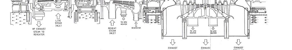
38 Extractions Usually extractions are avoided from HP stage because 1. The casing will be weakened if tap offs are constructed in it 2. There will be additional stress originated from thermal mass 3. Feed heating, using HP steam having high degree of super-heat will be uneconomical In 250 MW set of Budge Budge seven extractions are tapped offs from CRH, IPT (3 nos) & LPT (3 nos) 38
39 REHEATER SUPERHEATER EVAPORATOR ECONOMIZER Control Valves HPT Reheat Cycle LPT Steam path figure in a common reheat cycle Steam from final super-heater of the boiler is known as Main Steam Main Steam enters the HP turbine through control valves The exhaust of HP turbine (cold reheat) is reheated in the boiler Steam from re-heater of the boiler is known as Hot Reheat Hot Reheat steam enters the IP/LP turbine (through control valves) 39
40 Reheat System Introduction of re-heater results in pressure drop in the steam expansion path of turbine Therefore the number of reheat stages can not be many as the pressure drop will reduce efficiency of thermal cycle The steam pipes and re-heater coils are to be so designed to limit the drop to 2-3% The control valves in reheat steam path is not desirable, Systems using HPLP bypass require these valves to control steam flow during bypass operation 40
41 Constructional feature of steam turbine 41


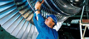
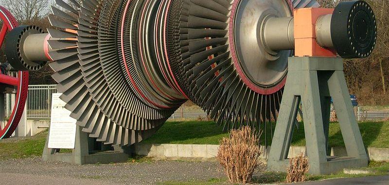
42 Typical Steam Turbine 42
43 Turbine types Large steam turbines have, many number of stages very high pressure & temperature of inlet steam large volume expansion of steam Therefore instead of single turbine cylinder multiple turbines are used Steam flow cascade from one turbine cylinder to another arranged in series &/or parallel Depending on inlet pressure of these multiple turbine cylinders, they are termed as HP, IP, LP 43

44 Turbine Construction Features Major Constructional features of a Turbine include: Cylinders (HP, IP, LP) and their assembly Steam admission valves and interconnecting pipes Gland Sealing Arrangements Bearings Thrusts and their lubrication system Expansion, locking and guide Barring arrangements Governing system 44
45 Turbine Construction Features Cycle Efficiency increase with temperature as well as pressure of inlet steam With the advancements of material science Turbine construction have also advanced over the past In older turbine design casing walls were very thick to cope with higher pressure Modern turbines are of double casing, which did away with many problems of older design 45
46 Turbine Construction Features In older turbine rotors construction were heavy and large bearings were needed to support them Modern turbine rotors are much lighter in comparison so are the bearings In some of the design one common bearing support two successive rotors 46

47 Turbine of BBGS Below is a sectional view of Budge Budge Turbine Of Unit 1,2 Different features of this turbine will be discussed 47

48 HP Turbine - BBGS 48

49 NCGS 2 HP CASING BOTTOM 49

50 NCGS 2 HP CASING BOTTOM 50


51 BBGS HP CASING 51
52 HP Turbine Glands - BBGS 52


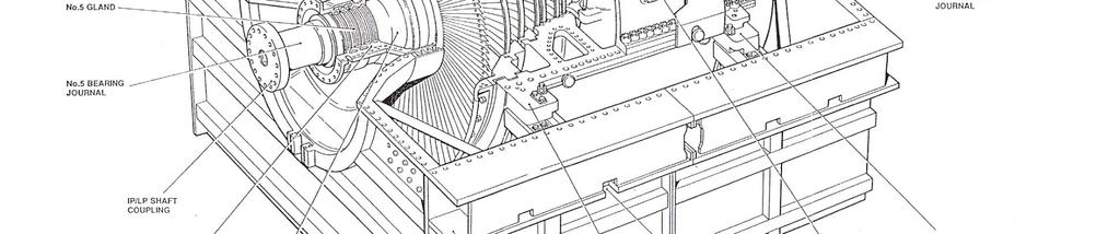
53 IP Turbine - BBGS 53


54 BBGS IP CASING 54
55 IP Turbine Glands- BBGS 55

56 LP Turbine - BBGS 56


57 LP SPINDLE NCGS 2 57
58 LP Turbine Glands- BBGS 58


59 BBGS LP CASING 59


60 BBGS LP CASING 60
61 TURBINE BEARINGS 61
62 Turbine Bearings- BBGS (Nos1,2 & 3) Bearing Nos 1 & 2 supports HP Turbine Rotor Bearing No 2 is combination of Thrust & Journal Bearing No 3 supports one end of IP Turbine Rotor 62
63 Turbine Bearings- BBGS (Nos 4,5,6&7) No 4 bearing supports the other end of IP rotor Similarly No 5 bearing supports one end of LP rotor And no 6 bearing supports the other end of LP rotor Generator rotor is supported by Nos 7 & 8 63
64 Turbine Bearings- BBGS Beyond No 8 is the No 9 bearing, which is housed in common chamber for Main Oil Pump, Barring Gear & its clutch Arrangement 64
65 Turbine Bearings- BBGS On the left is the figure of bearing No 2 which is a combination of Thrust and Journal On the right is the figure of remaining Journal bearings which are spherically seated 65


66 BBGS UNIT 1 BEARINGS 66


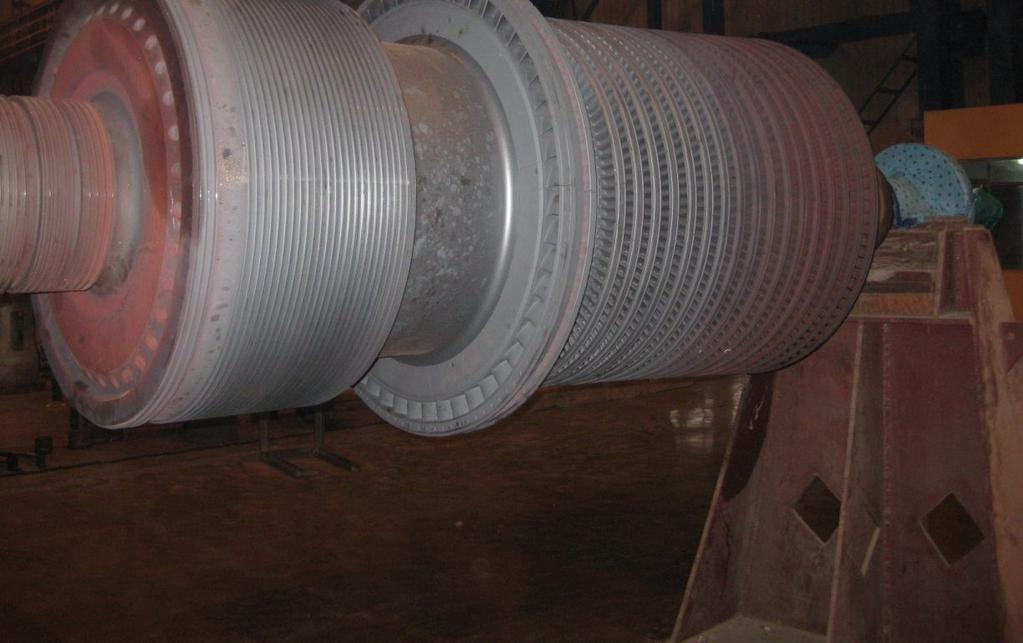
67 SGS BEARING NO. 2 BOTTOM 67
68 Turbine casing Turbine casings are of cylindrical shape having a horizontal parting joint The two halves are flanged at the parting plane and are jointed by bolts The resting paws are integral to bottom casing There can be one or more steam admission pipe connected to the casing 68
69 Turbine casing According to main steam pressure the thickness of casing used to be designed The shell thickness at HP end gradually reduces towards LP end Most of the early casing were built of cast steel machined to mount rows of blades With the increase of operating pressure the thickness of turbine casings went higher and higher 69
70 Turbine casing The increased thickness gave rise to number of problems these are Too heavy to machine/handle Difficulty to warm up avoiding undue thermal stress (Leading to start-up problem) Very long time to cool down To overcome this problem double casing turbine was evolved Then evolved barrel type design double casing Which gave faster start-up & load cycling feature and Lesser problem related to stress 70
71 Turbine casing The 250 MW Turbine set of Budge Budge power plant has 3 casings HP, IP & LP While the HP cylinder is completely double barreled, the IP & LP is also double casing but of different type The stator inner casings along with blade assembly are in annular segments housed on the outer casings LP outer casing has a sealing diaphragm to prevent any over pressurization 71

72 HP SINGLE CASING OF NCGS 2 72


73 BBGS HP INNER CASING 73
74 Turbine Rotor 74


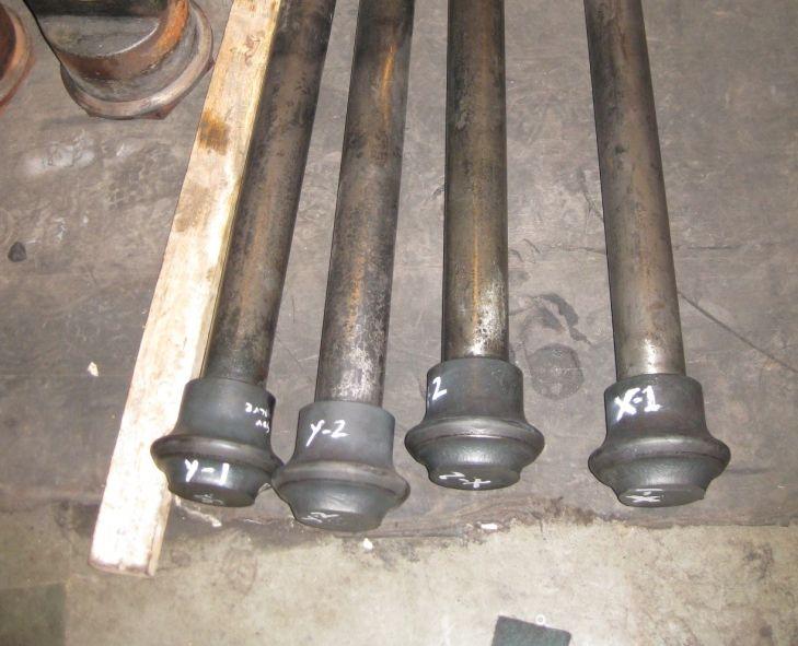
75 Turbine rotor 75
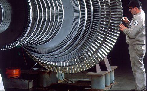
76 Turbine rotor Turbine rotors are machined out of a single steel forging Grooves are similarly machined to mount rotor blades Rotors are additionally featured with dummy piston, gland, bearing journal and coupling flange The metallurgy in turbine construction has evolved gradually over the years based on growing needs 76


77 BBGS IP AND LP TURBINE ROTOR 77
78 Blades and mounting arrangements 78
79 Turbine blades 79

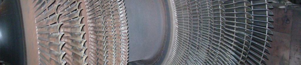
80 STEAM TURBINE BLADES 80
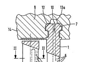
81 Blade mountings Blades are fixed singly or in groups into their grooves with the help of roots commonly configured like fur-tree Mounting arrangements of blades has to take care of the followings: Rigidity so that they do not give away to momentum of steam or vibrations Withstand high centrifugal force that rotor blades experience at 3000 rpm 81
82 Blade mounting arrangements The entire array has to be inserted through a open slot in the groove The requisite number of blades are thus inserted to form a circular array and are packed tightly by means of wedges Special locking arrangements to secure the lot is again an art of construction The rotor blades have to be specially assembled to avoid mass unbalance 82
83 Blade mounting arrangements Subsequent to blade assembly rotors are subjected to dynamic balancing and overspeed testing at shop and site before being put into service To correct any mass unbalance rotors are provided with adjusting screw which can be accessed from outside Blades at HP stages are usually provided with shrouds 83


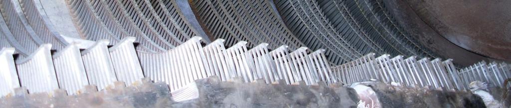
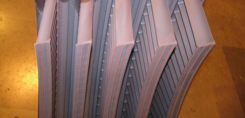
84 Blade mounting arrangements 84
85 Blade mounting arrangements LP blades are most critical to construct as they can be very long (900 MW sets can have blades 1.2 m long) LP blades made of steel cannot be used for making even longer blades Titanium alloys having high strength-todensity ratio is making progress LP blades are usually provided one or more laces to minimize vibration (other arrangements are also there) 85


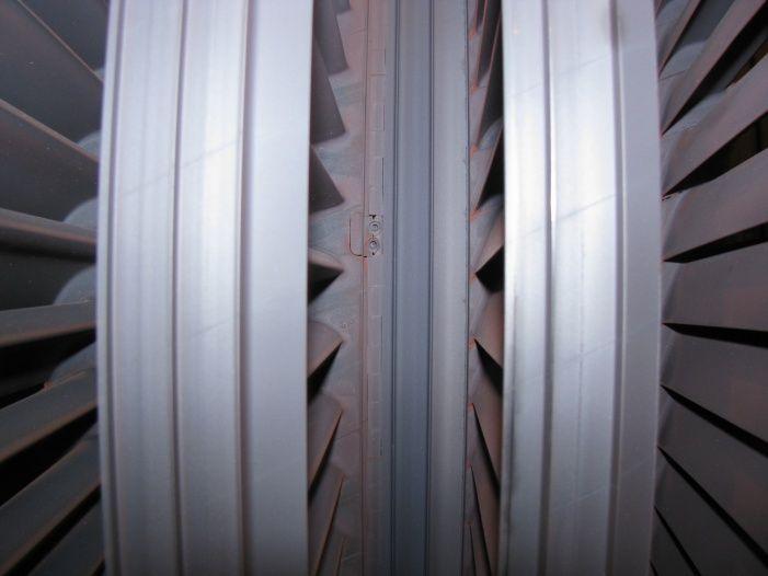
86 Interconnected tips of LP blade at BBGS Turbine 86


87 LP blade of BBGS Turbine 87
88 Blade mounting arrangements LP blades are also subjected to torturous operating conditions of handling very wet steam The water droplets impinge at very high velocity and cause erosion In order to prevent or minimize damage due to erosion, practices followed are: Putting of erosion shields on last few stages Blades are hardened to withstand impact Wet steam is partly bye passed to condenser 88
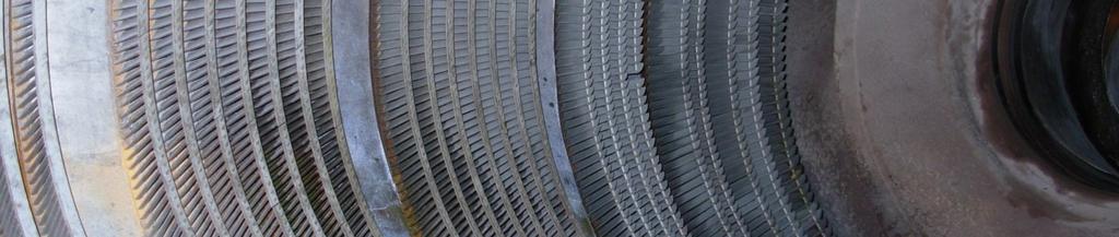
89 Turbine of BBGS HP turbine of Budge Budge has 17 stages of reaction blading over an above one impulse wheel The IP turbine has stages in 3 segments of reaction blading The LP turbine is double flow type having 7 rows of Left hand blades towards IP end and 7 rows of Right hand blades towards Generator 89


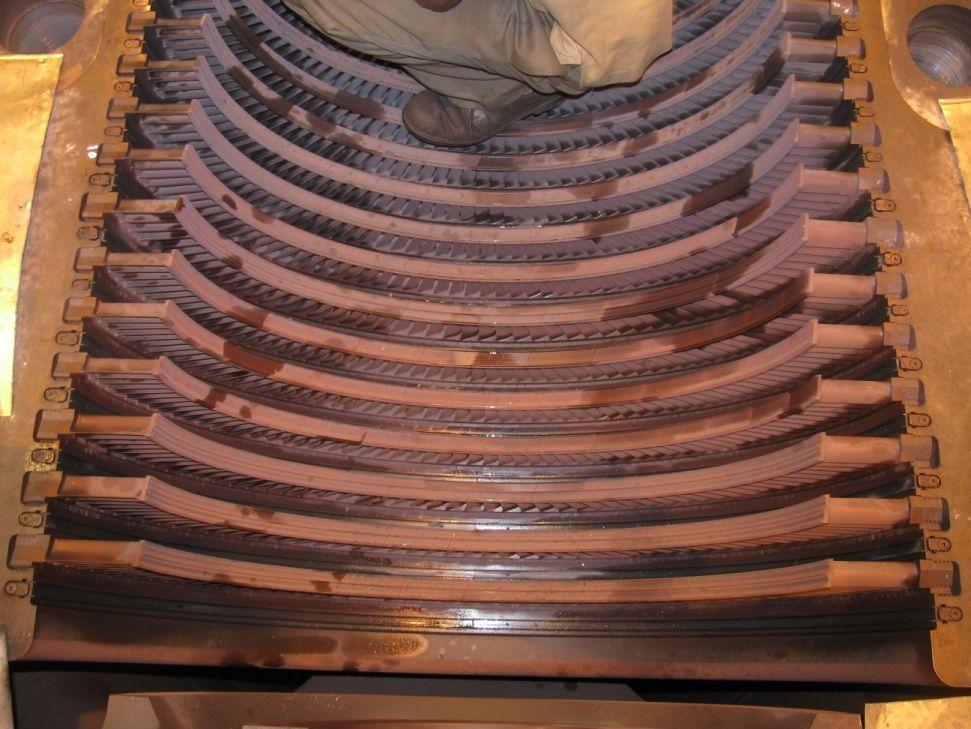
90 BLADE FITTING ARRANGEMENT AT BBGS 90
91 Most parts and components of steam turbines, are made of steels containing various amounts of the principal alloying elements chromium, molybdenum, vanadium and nickel, etc. Most high temperature rotors, valves and blades, etc. are made of high strength materials such as CrMoV steels and 12% Cr steels 91
92 Shrouds, Axial and Radial seals 92


93 Shrouds, axial and radial seals Figure on top shows the shrouds on blade tips Figure on left shows the photographs of turbine blades of various size and shape 93
94 Shrouds, axial and radial seals To prevent steam from bye passing the blade passage, the sealing arrangements are provided Both static and rotating blades are provided with seals Depending on their orientation with respect to the turbine axis these are termed as radial or axial Seal offers a more resistive path to steam in between stages 94
95 Shrouds, axial and radial seals Steam Static part (casing) Sealing tips Rotor There are very small clearances between the tips of static and rotating parts Multiple constrictions throttle the steam and creates a resistive path Shrouds over the blades are fitted with such seals 95
96 Shrouds, axial and radial seals Figures on the left show geometries of typical blade seals Designers adopt a configuration that suit best to specific requirement The seals play vital role in deciding internal efficiency of Turbine 96


97 SHROUDS AND SEALS 97
98 Material 15Cr11MoV is used as blade material for operation at 540 deg C 15Cr12WNiMoV is used as blades, fasteners, turbine disks & rotors for operation at deg C Both of these are Martensitic & Martensitic-Ferritic Steels C Cr Mo V W Ni 15Cr11MoV Cr12WNi MoV
99 Advancements The progress have been made in material technology in casting and forging techniques These have lead to development of steels for rotors, casings and turbine blading to suit steam conditions above 600 o C Adoption of advanced design techniques like finite element method in mechanical calculations use of computers in flow mechanics Has lead to development of 3-D blade profile that is 96% efficient and is gradually getting standardized 99
100 Advancements Improvement through the followings will contribute marginally in sealing techniques such as brush type glands use of abrasive coatings (like gas Turbine) Other major avenues are development of material science and further increase of steam temperature optimizing the cold end i.e. LP blading 100
101 Advancements To cover all sorts of demands from the market manufactures have gone for Standardizing modular product range as the present trend. The customer can choose from various standard models according to unit size, cost and specific needs Some such modules from Siemens/ Westinghouse USA are as follows ( These modules are the basic building blocks for higher ones) 101
102 Thrusts in a steam turbine 102
103 Thrust arrangements Thrust along the rotor axis in a turbine is generated due to 1. reaction force (axial component) due to change in axial momentum of steam between blade entry and exit 2. pressure difference between either sides of blades in a row (this is mainly applicable in reaction turbine) 3. friction in blade (in an impulse turbine thrust produced is only due to this) (direction of the force in 1 is opposite to those of 2 & 3) 103
104 Thrust arrangements The effect of all such forces produced by a single blade when summed up for the entire turbine produce huge amount of force There are various means by which the resultant thrust in the rotor is counter acted, these are: Counter flow arrangement Dummy pistons, applied with appropriate pressure on either sides 104

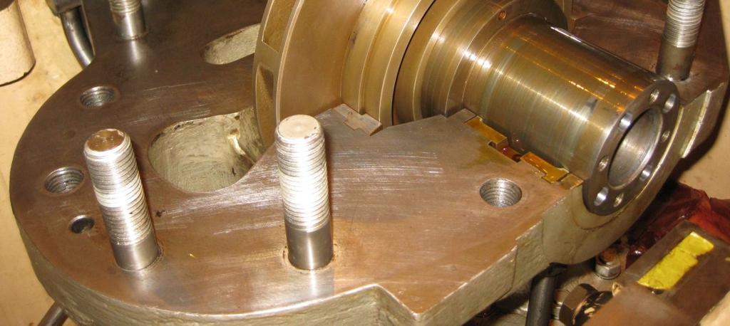
105 Thrust arrangements Dummy piston 105
106 Thrust arrangements Complete balance cannot be achieved for the entire range of turbine load with the above arrangement Collar (s) on rotor with oil lubricated thrust pads take the residual thrust Turbines having multiple cylinder & rotor can have one single thrust collar when rigidly coupled, otherwise rotors have individual thrust collars 106


107 TURBINE THRUST BEARING 107
108 Support anchor & expansion provision of Turbine Following slides are in reference to Budge Budge Turbine 108
109 Provision for Expansion Heating and cooling takes place in a turbine during start-up, shutdown and load changes Relative expansion and contraction also take place between various part Guides and keys are designed to accommodate the movement of cylinder, shaft due to thermal changes While doing so the relative alignment has to be maintained 109
110 Provision for Expansion HP & IP cylinders of Budge Budge unit 1,2 turbine have cumulative axial expansion from its anchor point at LP end of IPT towards HP end The LPT expands axially from its own anchor point in either direction Transverse expansion of cylinder take place from machine centre to maintain axial alignment Cylinders are supported on centerline permitting expansion in vertical plane & ensuring running clearances between shaft and cylinder 110

111 BBGS Turbine 111
 A B C D E F G H 112")
112 Supports and anchor of HP & IP Turbine at BBGS (elevation view) A B C D E F G H 112
113 Supports and anchor of HP & IP Turbine at BBGS (plan view) A B C D E F G H 113
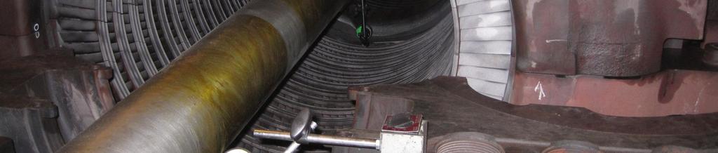
114 Provision for Expansion No 1 Bearing Block supports the free end of HP Turbine Nos 2 & 3 combined bearing blocks support coupled ends of HP & IP turbines Both blocks can slide freely on their pedestals The No 4 & 5 combined bearing blocks support coupled ends of IP & LP turbines has fix pedestal that acts as the anchor point for cylinder expansion 114
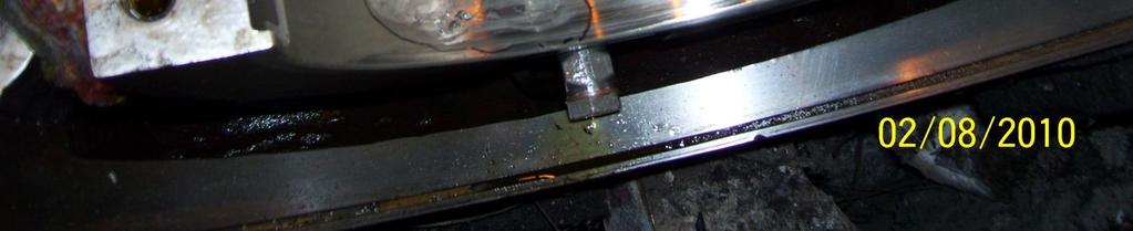
115 Provision for Expansion Wherever sliding movement has been envisaged between two relatively expanding surfaces anti-friction plates are placed Pointer and scale fitted on moving and stationary bodies give reading of expansion directly In order to monitor the expansion from control room position transducers (LVDT) are used in most modern turbines 115
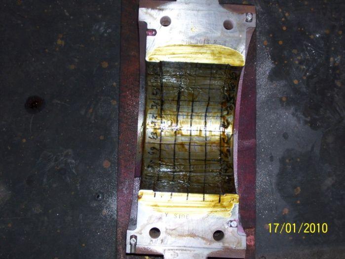
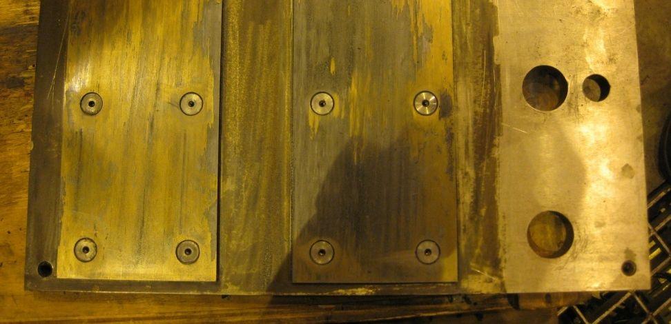
116 Provision for Expansion The figure on right are views of plan and elevation of LP turbine casing showing locking arrangement and provision for expansion 116


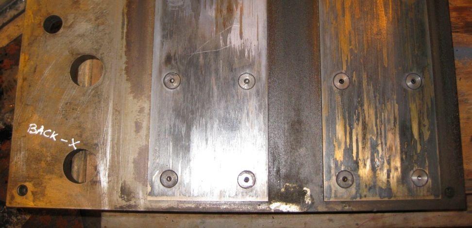
117 LUBRIDE PLATES FOR EXPANSION 117
118 Differential Expansion 118
119 Differential Expansion With increase of temperature, both rotor and the cylinder expands Ideally both of them are supposed to expand uniformly as both are heated by same steam Practically because of difference in thermal mass and conductive heat flow they expand unequally Differential expansion is the relative difference between the expansions of rotating shaft and stationary cylinder 119
120 Differential Expansion If expansion of stator be e s and expansion of rotor be e r, then conventionally differential expansion is e s e r In the above convention +ve increment of value will signify a relatively hot stator and vise-everse It is important to monitor differential expansion to ensure blade clearances are maintained Physical restraints on rotor is the thrust collar (located in no 2 bearing) 120
121 Differential Expansion As the IP cylinder expands with temperature the thrust collar on no 2 bearing housing moves towards HP end along with the rotor The IP rotor expands towards LP end from the thrust collar The HP rotor expands towards HP end from the thrust collar However relative movement of HP & IP shaft and cylinder can be assessed from No 1 & No 4 bearing housings respectively 121
122 Differential Expansion 122
123 Differential Expansion HPT Casing Rotor IPT e r e s e r e s Casing Anchor Movement e s(hpt) + e s(ipt) Movement e s HP differential Expansion is e s(hpt) - e r(hpt) IP differential Expansion is e s(ipt) - e r(ipt) 123
124 Differential Expansion Method of measurement of IP and HP differential expansion (refer to previous diagrams) The axial movement of shaft relative to the housings of No 2 & No 4 bearings give the respective differential expansions of HP and IP Turbine These movements are registered by sensors mounted on housings which senses markings on the shaft from very close proximity 124
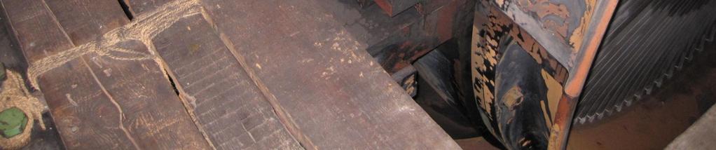
125 Differential Expansion Patterns known as Mark and Space is inscribed in a collar of the rotor A probe is positioned centrally above the collar The movement of shaft off sets the probe from the centre While the collar make a complete rotation it senses different intervals 125
126 Differential Expansion The figure on the left is the real version of differential expansion measurement markings in Budge Budge The bottom slot is cut to equalize any unbalance of mass due to the markings groves made on the top Differential expansion = Ratio (%)/Gain const. (where Ratio = Mark Count% (Mark Count + Space Count) 126
127 Differential Expansion Differential expansion of LP is assessed by deducting LP shaft movement from LP casing movement The measurement does not really indicate the sole differential expansion of LP because LP shaft movement is influenced by the effect of IP differential The turbine manufacturers specify the maximum & minimum limit values for each of these 127
128 Axial Position of Rotor The turbine rotor remains located by means of thrust collar and pad arrangement at a definite location (which is No 2 bearing for Budge Budge Turbine) The rotor can float axially only to the extent of gap that exist between the two pad assembly at front and rear of the collar and the collar itself In the event of excessive rotor-thrust the pads can wear off and the shaft location can get disturbed 128
129 Axial Position of Rotor It is important to monitor the position of a rotor of a turbine during normal running Some old machines had mechanical pointers to indicate shaft position, which at present have been replaced by electronic transducers Modern turbines incorporate trip from axial shift as a basic Turbine protection scheme 129
130 Turbine Barring Arrangement 130
131 Turbine Barring Once a running turbine is shut down, the shaft speed starts to "coast down and it comes to a complete stop Heat inside a turbine at stationary condition concentrate in the top half of the casing Hence the top half portion of the shaft becomes hotter than the bottom half. If the turbine shaft is allowed to remain in one position for a long time it tends to deflect or bend The shaft warps or bends only by millionths of inches, detectable by eccentricity meters. 131
132 Turbine Barring But this small amount of shaft deflection would be enough to cause vibrations and damage the entire steam turbine unit when it is restarted. Therefore, the shaft is not permitted to come to a complete stop by a mechanism known as "turning gear" or "barring gear" that takes over to rotate the shaft at a preset low speed. The barring gear must be kept in service until the temperatures of the casings and bearings are sufficiently low 132
133 Turbine Barring There are various drive systems to achieve this slow rotation, powered by electric or hydraulic motors They are mounted on the main shaft directly or through gears Barring speed usually range from 1 to 50 rpm When the turbine is speeded up the drive automatically disengage itself The engagement can either be manual or automatic At Budge Budge turbine the electrically driven turning gear can automatically disengage or engage itself during startup or shutdown 133

134 Turbine Barring 134
135 Turbine Barring (BBGS) Barring gear 135
136 Steam admission system Valve layouts 136
137 Steam admission & control valves In order to enable the final steam from boiler to enter the turbine, piping and valves are suitably arranged Boilers are usually provided with stop valves to isolate steam, for large units these are motorized Turbines are essentially equipped with steam valves for two purposes, these are known as: a) Emergency Stop Valve (ESV) that can shut off steam very quickly in case of turbine trip b) Governor Valves that regulate steam admission into the turbine according to its output loading 137
138 Steam admission & control valves REHEATER SUPERHEATER Boiler stop valve HRH NRV Turbine ESVs Governor Valves CRH NRV EVAPORATOR ECONOMIZE R HPT LPT The above is the schematic layout configuration of steam valve for normal turbines BOILER 138
139 Steam admission & control valves Piping layout for all the steam lines from boiler to turbine has to take care of the followings: Adequate support arrangement to sustain normal as well as shock load and also proper freedom of movement Provision for thermal expansion in accordance to the predetermined restrain and freedom of movement allowed in the support arrangements, thereby avoiding of undue stress Facility to drain out condensation that can accumulate during start up as well as normal running The draining arrangements should also allow steam flow to warm up the pipe line at a desired rate The pipelines has to be heat insulated according to their temperature levels to prevent stress and heat loss 139
140 Steam admission & control valves Sometimes due to space constraints linear expansion cannot be accommodated in a single run In such cases two popular method of expansions are shown Fig 1 is for high pressure applications Pipe Anchors Fig 1 Expansions Expansions Fig 2 Fig 2 in low pressure Pipe Anchors 140
141 Steam admission & control valves Pipes carrying steam from the boiler arrives at the Steam Chest close to the turbine Steam Chest is a thick walled casing divided into compartments that house the Emergency Stop Valve and Governor Valves Steam chests and are also fitted with strainers to trap objects that may be swiped by steam into the turbine Outlet pipes from Governor Valves enter into the turbine 141
142 Steam admission & control valves Emergency Stop Valve and Governor Valves are powered to open hydraulically against spring force The hydraulic systems can be of low pressure or high pressure types Hydraulic pressure derived from pumping arrangement of lubricating oil are usually Low pressure type of system High pressure systems have separate pumping units independent of lubricating system and can use special fire resistant fluid instead of hydraulic oil High pressure systems are lesser in size and faster in action compared to Low pressure version Outlet pipes from Governor Valves enter into the turbine 142
143 Steam admission & control valves Entry of steam into the turbine can be controlled by two basic means a)throttle Control b)nozzle Control By-pass governing is another method which is not very popular Schematic arrangements of throttle and nozzle governing are shown in Figure 1 & 2 Fig 1 Fig 2 ADMISSION CHAMBER P1 P2 P3 P4 143
144 Steam admission & control valves The H-S diagram shows the principle difference between the two modes In case of nozzle governing there is a throttle loss in intermediate positions of nozzle control valves, [ i.e. between two valve points (vide previous figure); During turbine loading, when (say) P1, P2 is full open while P3 is part open (and P4 shut)] Enthalpy (H) ΔH in full Load inlet pressure Throttling at governor valve Full Load Pressure 1 2 Part Load Pressure Entropy (S ) 1 Enthalpy drop from 1-2 is more compared to that from ΔH in part Load inlet pressure Condenser Pressure 144


145 BBGS STEAM VALVES 145
146 Turbine Governing 146
147 Need for Governing Governors are associated with all Turbo- Generators to control the working fluid entering the prime-mover The fluid can vary from water (for hydel plants) to steam (for thermal) or fuel (for Gas Turbine) The basic control elements are valves capable of controlling the required quantum accurately Functioning of governor is basically to interpret signals and power of the valves accordingly The mechanism has developed from very simple arrangement to a complicated system to meet ever growing needs 147
148 Need for Governing There can be two situations envisaged in understanding the basics of Governors a) Single Machine Operation: Under this condition One Turbo-generator supplies to a group of Load connected to it b) Parallel operation of Turbo-generators: In this case Two or more parallel connected Turbo-generator supplies a common Load (The following slide shows the single line configurations of the above two systems) 148
149 Single & Parallel operation of TG TG1 TG2 : TGm ~ ~ ~ ~ ~ L 1 L 2 : : L n L 1 L 2 : : L n SINGLE TG OPERATION PARALLEL TG OPERATION 149
150 SINGLE TG OPERATION A Turbo Generator operating under a steady load condition is assumed to possess: Fixed speed (say synchronous speed of Alternator) Fixed governor valve opening, that admits exact amount of fluid to produce the connected power The state remains in equilibrium if not disturbed If the equilibrium is disturbed by increment of load from the previous state then: The TG will try to meet the excess load demand from its storage of rotational kinetic energy The speed of turbine will therefore decelerate 150
151 SINGLE TG OPERATION Similarly if there is a decrease of connected load then The TG will have additional prime moving power to add up to its storage of rotational kinetic energy The net effect will be acceleration of TG speed Either of these situations are unstable and not desirable for the machine and its connected load Governors are intended to keep the speed of TG at a steady level by regulating the flow into the prime-mover under the aforesaid conditions 151

152 SINGLE TG OPERATION A simple arrangement of valve control is shown in the figure In response to falling speed (i.e. higher load) the fly-balls drop down that opens valve via lever arm to admit more fluid The additional fluid flow copes with increased demand and retain speed (Vice-verse happens under rising speed) The basic components that accomplish the process are: a. Speed variation sensor (Fly ball) b. Control function (Linear movement in proportion to change in rpm ) c. Actuator drive (Lever arm that powers the movement of valve) d. Final control element (The valve that regulate flow) b a d c 152
153 SINGLE TG OPERATION From this simple device it is evident that corresponding to every position of fly-ball the control valve has a definite opening The two aspects in the process can be interpreted as The position of fly-ball to represent speed of TG The opening of control valve to represent steam flow & TG loading Relationship that exists between these two parameters, known as Governor Characteristic is shown in the plot (vide figure) Speed (rpm) 3000 (rpm) 3180 (rpm) Maximum continuous rated load Load Zero Load 153
154 SINGLE TG OPERATION The regulation characteristic is drooping in nature (i.e. the valve close with rise in speed) that ensures a stable operating point Every governor has its intrinsic droop character that decides the extent of speed change that can bring about a 100% load change This is usually expressed as change of frequency as the percentage of rated frequency [The co-ordinates characteristic can also be otherwise, viz, speed (x) vs load (y)] Zero Load Load Maximum continuous rated load 6% droop 3000 (rpm) 3180 (rpm) Speed (rpm) 154
155 SINGLE TG OPERATION The droop characteristics of conventional governors were fixed by their design and construction to somewhere between 5-8% droop In the modern design (hydraulic/ electrohydraulic type, specially with µ-processors) the droop can be changed suitably Load Maximum continuous rated load Zero Load 50 Hz 2% to 8% droop characters 52 Hz 53 Hz 54 Hz 51 Hz Frequency 155
156 SINGLE TG OPERATION Governing of modern high capacity steam turbines are scaled up version of the simple governing system, but principles are same: a. Speed sensors pick up signals from: Fly balls, Oil Pressures, Voltage, Digital Pulses (etc) b. Control function can be obtained from: mechanical/ hydraulic arrangements, analog or digital computers c. Actuator drive are mostly: hydraulic drives with mechanical or electronic coordination d. Final control element constitute of steam admission valves 156
157 SINGLE TG OPERATION Mechanical arrangements has been reliably used to detect speed Speed can be translated into hydraulic signal (relay oil pressure) to control governor valve opening and load thereby Change of relay oil pressure is small and is incapable of overcoming large forces of spring / steam pressure and move the valves The pilot plunger and main valve piston acts as a hydraulic amplifier that operate the steam admission valves 157
158 SINGLE TG OPERATION The basic governing is also provided with some additional features such as: Over-speed protecting system known as over-speed governor (in the scheme shown centrifugal action on slight off-centric bolt operate a plunger at set speed) The hydraulic oil is used in various steps as control oil each assigned to a definite purpose Trip oil is one such that enable governing only when the system oil pressure is available Trip plunger both for over-speed and manual trip need to be reset for development of pressure The figure in the next slide is a schematic of such simple governing system 158
159 SINGLE TG OPERATION PILOT PLUNGER O RELAY VALVE O O POWER PISTON O O O O O RELAY OIL GOVORNOR VALVE FLY-BALL SPEED SENSOR MANUAL TRIP PLUNGER HIGH PRESSUE OIL FROM PUMPS PRESSURE CONTROL ORIFICE O OVERSPEED GOVERNOR TRIP OIL Schematic of Governing OVERSPEED TRIP PLUNGER 159
160 SINGLE TG OPERATION Speed can also be sensed as oil pressure (H N 2 ) developed by an impeller rotating at shaft speed Governors of modern power plants also incorporate various load limiting functions that arises out of process parameters, such as Load restriction due to any shortcoming/ de-rating Load restriction due to pressure fall Load restriction due to vacuum fall The following slide give brief introduction to those 160
161 SINGLE TG OPERATION PRESSURE UN-LOAD VACUUM UN-LOAD LOAD LIMITER O O O O O O O O O Schematic of Governing 161
162 PARALLEL TG OPERATION When a number of Turbo Generators run in parallel the notion of speed governing has no relevance individually All the sets collectively respond to rise or fall of frequency by shutting or opening their governor valves respectively The extent of load change take that place in ideal case is in according to the governor characteristic of individual TG sets Turbo-generators connected to an infinite grid* have lot more control inputs other than speed *(total connected load is very large compared to TG rating) 162
163 PARALLEL TG OPERATION The following example show Load sharing of 2 sets The frequency is at O (say) The loading of two sets are OA & OB (Total load = OA+OB) The frequency rises by f to O The operating points shifts from A to A & B to B The loading of two sets changes to O A & O B Zero Load Load 3000 (rpm) Maximum continuous rated load New load O A +O B < OA+OB Speed (rpm)/ Freq (Hz) A B O A B f O 163
164 PARALLEL TG OPERATION It can be shown that similar event of load sharing would happen under falling frequency Also the similar of load redistribution will take place if there are more than 2 TGs in the system In an infinite bus the change of frequency can be originated from load changes beyond the scope of the TGs concerned Then, if the sharing of load has to depend on droop character only (as shown) the TG would not be able to deliver its stipulated load 164
165 PARALLEL TG OPERATION In order to cope up with such situation small change was done in governing system The basic intentions are To support the system under frequency changes so as to ensure its stability (i.e. add MW generation if frequency falls or shed MW generation if frequency rise) To redistribute the load according to their capabilities of individual machines, as the droop characteristics of all are not same To regain the original load status gradually once the frequency has stabilized to a new value 165
166 PARALLEL TG OPERATION This figure show how the TG can recover its load after giving initial support to the system The frequency is at O (say) The loading the TG is OA (which is part of System Load) The frequency rises by f to O The operating points shifts from A to A (OA <OA, to support the cause of frequency change) The machine can go back to its previous load condition if the Governor line be shifted to A, (OA=OA ) Zero Load Load 3000 (rpm) Maximum continuous rated load A O f O A A Speed (rpm) 166
167 PARALLEL TG OPERATION The simple arrangement depicts how a governor picks up after a load-drop due to frequency rise With the rise in frequency the fly-balls move out pulling the sleeve back and uncovering the oil port As more oil gets drained the relay oil pressure falls, so does the load The port can be arranged to move back into the sleeve that will restore the previous opening as well as load O O O O O O O O O 167
168 PARALLEL TG OPERATION The provision to move the plunger having graduated port allows manipulation of relay oil pressure and load in either direction This feature (or other equivalent mechanisms in a different model) enables raising and lowering of load independent of frequency The effect of above manipulation on governor is actually observed as the characteristic line to move up or down in parallel In other words, corresponding to every position of the plunger port there is a characteristic line 168
169 PARALLEL TG OPERATION There can be unlimited number of characteristic curves as shown Above TMCR/ VWO load value, the lines are virtual as no operating point can be envisaged (physical limit in valve opening and steam flow will restrict the TG load) The machine can be made to operate at any point below it VWO TMCR Load 50 Hz Frequency (Hz) 169
170 MODERN TRENDS IN GOVERNING ELECTRO HYDRAULIC 170
171 ELECTRO HYDRAULIC GOVERNOR Turbine Governing should essentially be: 1. Rugged 2. Reliable & 3. Responsive (and preferably adaptive) The hydraulic and mechanical models definitely satisfied the first two conditions The advanced microprocessor technology could translate the entire governor control algorithm into software 171
172 ELECTRO HYDRAULIC GOVERNOR Selection of appropriate hardware architecture could make the system to satisfy all three conditions Many more than the basic features relevant in present power system have been possible to be incorporated in real-time µp control These comprises the Electro Hydraulic Governor (EHG), the hydraulic system only powers the movement of valve 172
173 TURBINE LUB OIL SYSTEM 173
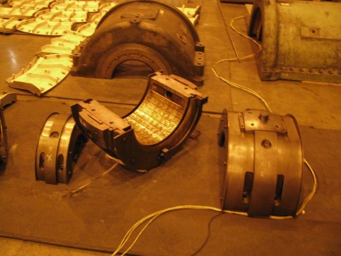
174 TGS TURBINE LUB OIL PID 174
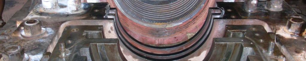
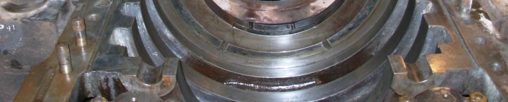
175 Bearings and Lubrication Forced Lubrication: Comprises of pumps that pressurize oil & supply to bearing Return oil from the bearings is collected back to the sump Usually the pumping system includes, pressure control feature, filters and coolers Pump Control Valve Bearung Shaft Sump Cooler Filter Return Oil 175
176 Bearings and Lubrication Each of the turbine shaft is supported on either ends by journal bearings and are forced lubricated by low viscous oil The oil is filtered to remove solid particles and centrifuged to remove any water In turbines where two shafts are rigidly coupled the common coupled end can be supported by single bearing A journal bearing consists of two half-cylinders that enclose the shaft They are internally lined with Babbitt, a metal alloy usually consisting of tin, copper and antimony 176
177 Bearings and Lubrication Alignment and clearances in a bearing decide a lot of the turbine performance To allow minor misalignment/ distortion of shafts, the bearings are mounted inside the housing fitted with spherical pads This bearings can self-adjust themselves while running and can take up minor distortions Since the shafts are quite heavy, it is difficult to establish a proper the lubricating layer between the shaft and bearing In Budge Budge turbine bearings lubricating oil enters through twin ports at horizontal joints 177
178 Bearings and Lubrication Figure to the right is of a typical spherically seated bearing All the bearings of BBGS turbine are of this type The housings have provision to mount temperature monitoring device (to reach to the depth of white metal) 178
179 Bearings and Lubrication The lubricating layer also saves the white metal (having low melting point) from receiving heat from the hot turbine shaft The turbine requires to be adequately speeded up before a wedge pressure is established below the shaft to sustain the shaft load Before a turbine has sufficiently speeded up, oil at high pressure is applied below each shaft to jack up and make them free to rotate In Budge Budge turbine jacking oil enters through twin ports from the bottom of the bearing 179
180 Bearings and Lubrication The clockwise movement of shaft drags the lubricating oil as shown The drag force generates a pressure below the shaft Higher the speed of shaft more oil is dragged and the magnitude of force also increase As this resembles a wedge acting between shaft and bearing, the pressure is called wedge pressure Turbine Shafts are lifted up slightly after a certain speed which help to minimize rotational resistance SHAFT Upward thrust on shaft due to fluid pressure below the shaft Bearing 180

.")
181 OIL WEDGE THICKNESS During normal operation, the shaft rotates at sufficient speed to force oil between the conforming curved surfaces of the shaft and shell, thus creating an oil wedge and a hydrodynamic oil film. This full hydrodynamic fluid film allows these bearings to support extremely heavy loads and operate at high rotational speeds. Surface speeds of 175 to 250 meters/second (30,000 to 50,000 feet/minute) are common. Temperatures are often limited by the lubricant used, as the lead and tin babbitt is capable of temperatures reaching 150 C (300 F). It is important to understand that the rotating shaft is not centered in the bearing shell during normal operation. This offset distance is referred to as the eccentricity of the bearing and creates a unique location for the minimum oil film thickness. Normally, the minimum oil film thickness is also the dynamic operating clearance of the bearing. Knowledge of the oil film thickness or dynamic clearances is also useful in determining filtration and metal surface finish requirements. Typically, minimum oil film thicknesses in the load zone during operation ranges from 1.0 to 300 microns, but values of 5 to 75 microns are more common in midsized industrial equipment. 181
182 Bearings and Lubrication Single line diagram showing Lub-oil distribution layout and instrumentation for BBGS turbine 182
183 Bearings of BBGS units Bearing No1 183
184 Bearings of BBGS units Bearing Nos 2 & 3 184
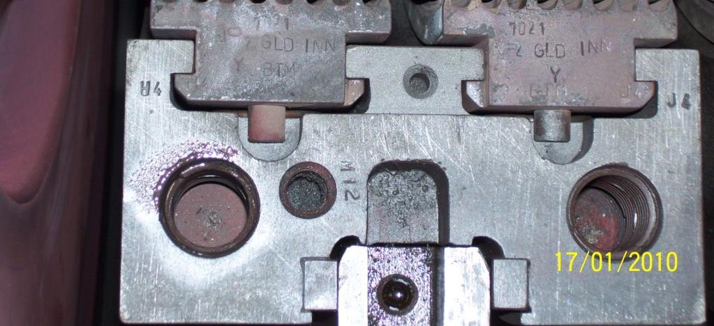
185 Bearings of BBGS units Bearing No 2 of BBGS is a combination of thrust and journal bearing Figure on right is the split up view of the same 185
186 Bearings of BBGS units Bearing Nos 4 & 5 186
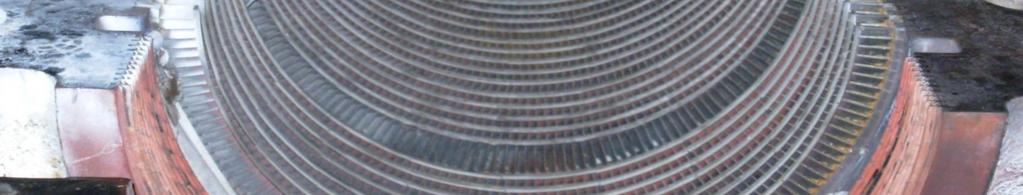
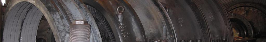
187 Bearings of BBGS units Bearing No 6 & 7 187
188 Bearings of BBGS units Bearing No 8 188
189 Bearings and Lubrication There are certain important monitoring parameter pertaining to shaft and bearings, these are: Bearing metal temperatures Drain oil temperatures Pedestal vibration Shaft vibrations (usually measured in two positions 90 o apart) The parameters can be utilized to analyze shaft behaviour and diagnose problems 189

190 MOP OF BBGS 190
191 GLAND SEALING SYSTEM OF A STEAM TURBINE 191
192 BBGS 3 SEAL STEAM SYSTEM PID 192

193 Shaft seals 193
194 Shaft seals It is important to seal the turbine internal from the outer atmosphere as The inner part contains steam at high pressure during normal running and Vacuum during start up The former results in steam (heat) loss while the later may lead to ingress of foreign elements getting sucked inside LP turbine however have pressure less than atmosphere continuously 194
195 Shaft seals Either ends of rotor shaft that come out from stator need such seals Both the stator and rotor have typical arrangements known as glands Conditioned Steam provides excellent sealing medium in modern turbines, while some old turbines use this in combination to Carbon glands The glands of HP IP & LP differ from one another constructionally 195


196 Shaft seals The glands are spring backed labyrinth type arranged in segments termed as inner gland and outer gland Port opening between each segments allow steam to enter or leak off The grooves on the rotor accommodates to the stator segments 196
197 Shaft seals O To GS condenser From GS supply Bus HP SHAFT I To DA BS O IP/LP SHAFT To GS condenser I Figures on left show steam distribution arrangement in glands of Budge Budge Turbine There are cavities between segments connected to the points as labeled HP Gland at BBGS IP/LP Gland at BBGS 197

198 HP Turbine Glands - BBGS 198

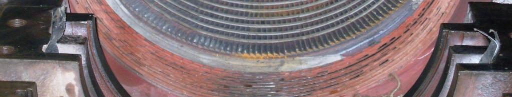
199 IP Turbine Glands- BBGS 199
200 LP Turbine Glands- BBGS 200
201 Shaft seals During normal operation the gland ring segments are held by spring pressures against the shoulders of T shaped grooves in gland housing Movement towards shaft is thereby limited, so that the fins maintain predetermined distance from the shaft This arrangement can take up disturbances in shaft that tend to bring contact between static and rotating parts 201
202 Shaft seals In such an event the segments can move radially outward against spring pressure and limit the contact pressure Low pressure Steam with sufficient degree of superheat is used for gland sealing This is normally obtained from a PRDS station As the LP gland steam requires a lower temperature additional de-superheating has to be done 202

203 LABYRINTH SEALS 203
204 HP LP Bypass System Concepts & Component Description 204
205 MS PID FOR BBGS UNIT 3 205
206 Basic concepts of HP LP Bypass Need to have HP LP Bypass To prevent Steam loss during start-up / shut down To control boiler temperature during cold starts Matching of boiler outlet steam parameter with that of turbine metal during hot starts Allow transient excess steam flow under load throw off saving boiler safety valve operation Protect re-heater during such transient Avoid boiler trip in the event of turbine trip 206
207 Basic concepts of HP LP Bypass HP Bypass arrangement LP Bypass arrangement Atemperation spray to match the downstream conditions REHEATER SUPERHEATER EVAPORATOR ECONOMIZER BOILER HPT To Condenser LPT 207
208 Basic concepts of HP LP Bypass Main Steam from boiler is bypassed into Cold Reheat line i.e. HP turbine exhaust Steam, after flowing through Reheat stage in boiler is again dumped to the condenser before entering the intermediate turbine The condenser cooling water condense the steam and carry away the heat Although there is a considerable heat loss in the process but the gains surpasses losses 208
209 Basic concepts of HP LP Bypass The total flow handling capacity can vary from 30 to 100% of turbine MCR steam flow depending on the size of the valves For large units this can be achieved by using more than one valve in parallel HPLP bypass system having lower capacity can mainly cater to start up and shutdown requirements but cannot provide boiler protection 209
210 Basic concepts of HP LP Bypass High Capacity system are designed to prevent boiler trip and over pressurizations due to disturbances external to boiler The system has become so reliable that some units consider HPLP bypass as a substitute to boiler safety valve (for 100% HPLP Bypass) In the above case the valves should have a very fast response* and very good pressure regulation characteristic 210
211 Basic concepts of HP LP Bypass The bypass system usually remains dormant during normal running of unit When required it has to act immediately, therefore the following features are essential: A supply unit that provide hydraulic oil at required pressure all the time Warm up arrangement to avoid thermal shock during any sudden operation after long time A continuous watch dog monitoring system 211
212 Components in HP LP Bypass HP Bypass system 212
213 HP Bypass system The HP Bypass system consists of a) A pressure reducing valve b) Associated spray water control valve c) An atemperator to cool the steam downsream of pressure control valve d) All control valves have actuators powered hydraulically e) Field Control devices (servo, solenoid valves etc) and instrumentation (sensors for pressure, temperature, position, etc.) 213
214 HP Bypass system The HP pressure reducing valve can reduce the pressure from rated turbine inlet pressure to the cold reheat pressure There is an atemperator unit, either separate or integral to the main valve The atemperator brings the temperature down to suit the CRH steam parameters Discharge from boiler feed pump is used for tempering the steam 214
215 HP Bypass system The HP pressure reducing valve can be designed to open either aided by the main steam pressure or against it [The former type is then a pressure safety device*] The valve capacity determines its aperture design The valves are provided with sophisticated hydraulic actuators that can open or close the valve at normal as well as fast rate 215
216 HP Bypass system at Budge Budge The HP pressure reducing valve at Budge Budge is of Sulzer make and is steam to open type It is designed to for 60% TMCR steam flow at rated pressure The pressure reduction and atemperation is within the same valve chamber This valve is therefore designed with an unique profile that can withstand stress due to sharp temperature gradient between inlet and outlet Discharge from boiler feed pump supplies the spray water through control valves 216
217 HP Bypass system at Budge Budge During normal running when the steam valve will remain shut spray water should not find its way to the valve Since the spray water through control valve cannot ensure tight shut off, an additional isolating valve is provided The feed water lines also have a warm up line to avoid sudden change in pipe line temperature The pressure control valve opens on sensing its upstream pressure and as long as it remains open it tries to maintain a set pressure 217
218 HP Bypass system at Budge Budge While the pressure control valve is open the water isolating valve opens fully The temperature controller senses downstream temperatures and modulate the valve to maintain a set temperature A steel cage in atemperator chamber ensures proper mixing of steam and water Both the water valves shut close as soon as the pressure control valve closes HP bypass valve actuator is specially designed to open very fast under sharp load throw off, so that the boiler operation is not affected 218

219 HPBP Valve The drawings show construction of the HP Bypass valve of BBGS 219
Fundamentals of steam turbine systems
 Principles of operation Fundamentals of steam turbine systems - The motive power in a steam turbine is obtained by the rate of change in momentum of a high velocity jet of steam impinging on a curved blade
Mohammad Faisal Haider. Department of Mechanical Engineering Bangladesh University of Engineering and Technology
 Mohammad Faisal Haider Lecturer Department of Mechanical Engineering Bangladesh University of Engineering and Technology Steam Turbine 2 Vapor Power Cycle 4 5 Steam Turbine A steam turbine is prime mover
PRODUCTS. Multi-Stage Steam Turbines. Proven reliability and efficiency
 PRODUCTS Multi-Stage Steam Turbines Proven reliability and efficiency Introduction Proven Reliability and Efficiency Dependable, versatile turbomachinery is essential for today s refinery, chemical process,
CH.4 Basic Components of Hydraulic and Pneumatic System/16 M HAP/17522/AE5G
 Content : 4.1 Hydraulic and Pneumatic actuators. 10 Marks Hydraulic Actuators - Hydraulic cylinders (single, double acting and telescopic) construction and working, Hydraulic motors (gear and piston type)
AGN 076 Alternator Bearings
 Application Guidance Notes: Technical Information from Cummins Generator Technologies AGN 076 Alternator Bearings BEARING TYPES In the design of STAMFORD and AvK alternators, the expected types of rotor
STEAM TURBINE MODERNIZATION SOLUTIONS PROVIDE A WIDE SPECTRUM OF OPTIONS TO IMPROVE PERFORMANCE
 STEAM TURBINE MODERNIZATION SOLUTIONS PROVIDE A WIDE SPECTRUM OF OPTIONS TO IMPROVE PERFORMANCE Michael W. Smiarowski, Rainer Leo, Christof Scholten, Siemens Power Generation (PG), Germany John Blake,
Process 1-2: Reversible adiabatic compression process. Process 2-3: Reversible isothermal heat addition
 Vapor Power Cycles Process 1-2: Reversible adiabatic compression process from P1 to P2. Process 2-3: Reversible isothermal heat addition process at constant temperature TH. Process 3-4: Reversible adiabatic
Steam Turbines and Gas Expanders. Reliability, Efficiency, Performance
 Steam Turbines and Gas Expanders Reliability, Efficiency, Performance Introduction Proven Reliability and Efficiency Dependable, versatile turbomachinery is essential for today s refinery, chemical process,
Thermal Unit Operation (ChEg3113)
") Thermal Unit Operation (ChEg3113) Lecture 5- Heat Exchanger Design Instructor: Mr. Tedla Yeshitila (M.Sc.) Today Review Heat exchanger design vs rating of heat exchanger Heat exchanger general design procedure
Thermal Unit Operation (ChEg3113) Lecture 5- Heat Exchanger Design Instructor: Mr. Tedla Yeshitila (M.Sc.) Today Review Heat exchanger design vs rating of heat exchanger Heat exchanger general design procedure
Metrovick F2/4 Beryl. Turbo-Union RB199
 Turbo-Union RB199 Metrovick F2/4 Beryl Development of the F2, the first British axial flow turbo-jet, began in f 940. After initial flight trials in the tail of an Avro Lancaster, two F2s were installed
CLASSIFICATION OF ROLLING-ELEMENT BEARINGS
 CLASSIFICATION OF ROLLING-ELEMENT BEARINGS Ball bearings can operate at higher speed in comparison to roller bearings because they have lower friction. In particular, the balls have less viscous resistance
Bearings. Rolling-contact Bearings
 Bearings A bearing is a mechanical element that limits relative motion to only the desired motion and at the same time it reduces the frictional resistance to the desired motion. Depending on the design
Al- Ameen Engg. College. Fluid Machines. Prepared by: AREEF A AP/ ME AL AMEEN ENGINEERING COLLEGE Shoranur.
 Fluid Machines Prepared by: AREEF A AP/ ME AL AMEEN ENGINEERING COLLEGE Shoranur Classification of hydraulic machines HYDROULIC MACHINES (I) Hydraulic Turbines A hydraulic machine which converts hydraulic
three different ways, so it is important to be aware of how flow is to be specified
 Flow-control valves Flow-control valves include simple s to sophisticated closed-loop electrohydraulic valves that automatically adjust to variations in pressure and temperature. The purpose of flow control
FUNCTION OF A BEARING
 Bearing FUNCTION OF A BEARING The main function of a rotating shaft is to transmit power from one end of the line to the other. It needs a good support to ensure stability and frictionless rotation. The
Unit V HYDROSTATIC DRIVE AND ELECTRIC DRIVE
 Unit V HYDROSTATIC DRIVE AND ELECTRIC DRIVE HYDROSTATIC DRIVE In this type of drives a hydrostatic pump and a motor is used. The engine drives the pump and it generates hydrostatic pressure on the fluid.
WINTER 14 EXAMINATION
 WINTER 14 EXAMINATION Subject Code: 17413(EME) Model Answer Important Instructions to examiners: 1) The answers should be examined by key words and not as word-to-word as given in the model answer scheme.
Chapter 6. Supercharging
 SHROFF S. R. ROTARY INSTITUTE OF CHEMICAL TECHNOLOGY (SRICT) DEPARTMENT OF MECHANICAL ENGINEERING. Chapter 6. Supercharging Subject: Internal Combustion Engine 1 Outline Chapter 6. Supercharging 6.1 Need
TURBINE DESIGN NEED OF THE HOUR
 TURBINE DESIGN NEED OF THE HOUR By:- A. P. Samal AGM(PE-Mech / TG) Abstract Starting with the success of bulk tendering projects NTPC has installed a new fleet of supercritical and ultra-supercritical
LECTURE-23: Basic concept of Hydro-Static Transmission (HST) Systems
 Systems") MODULE-6 : HYDROSTATIC TRANSMISSION SYSTEMS LECTURE-23: Basic concept of Hydro-Static Transmission (HST) Systems 1. INTRODUCTION The need for large power transmissions in tight space and their control
MODULE-6 : HYDROSTATIC TRANSMISSION SYSTEMS LECTURE-23: Basic concept of Hydro-Static Transmission (HST) Systems 1. INTRODUCTION The need for large power transmissions in tight space and their control
walton TEMPERATURE CONTROL SYSTEMS Pneumatically Operated (Rotary)
") walton TEMPERATURE CONTROL SYSTEMS Pneumatically Operated (Rotary) WALTON ENGINEERING CO. LTD. 61 London Road St Albans Hertfordshire AL1 1LJ England Telephone +44 (0)1727 855616 Fax +44 (0)1727 841145
walton TEMPERATURE CONTROL SYSTEMS Pneumatically Operated (Rotary) WALTON ENGINEERING CO. LTD. 61 London Road St Albans Hertfordshire AL1 1LJ England Telephone +44 (0)1727 855616 Fax +44 (0)1727 841145
Gauges, Sight Glasses and Vacuum Breakers
 Gauges, Sight Glasses and Vacuum Breakers Gauges, Sight Glasses and Vacuum Breakers Gauges Pressure gauges Pressure gauges should be installed in at least the following situations: Upstream of a pressure
Differential Expansion Measurements on Large Steam Turbines
 Sensonics Technical Note DS1220 Differential Expansion Measurements on Large Steam Turbines One of the challenges facing instrumentation engineers in the power generation sector is the accurate measurement
Control of Heat Processes
 PG 30 kwietnia 2011 Slide 1 of 66 Turbine power PG test P = m ṁ 0 H η i η m η g m coefficient which takes into account extraction flows Slide 2 of 66 Turbine regulation PG 1. Quantative adjustment varied
Document Code: 1 (8) Issuing date: Status:
 Issuing date: Status:") Document Code: 1 (8) Project : MULTI FUEL CFB BOILER SIMULATOR Author: Approved: Employer: JJA Document title: SYSTEM DESCRIPTION TURBINE CONTROL Submitted for: Employer reference: Other information: Document
Document Code: 1 (8) Project : MULTI FUEL CFB BOILER SIMULATOR Author: Approved: Employer: JJA Document title: SYSTEM DESCRIPTION TURBINE CONTROL Submitted for: Employer reference: Other information: Document
Chapter 7: DC Motors and Transmissions. 7.1: Basic Definitions and Concepts
 Chapter 7: DC Motors and Transmissions Electric motors are one of the most common types of actuators found in robotics. Using them effectively will allow your robot to take action based on the direction
The Enhanced Platform
 Power Generation The Enhanced Platform The Next Generation of Industrial Steam Turbines www.siemens.com / energy / steamturbines Advanced Steam Turbine Design Figure 1: Enhanced Platform Design The Enhanced
A pump is a machine used to move liquid through a piping system and to raise the pressure of the liquid.
 What is a pump A pump is a machine used to move liquid through a piping system and to raise the pressure of the liquid. Why increase a liquid s pressure? Static elevation a liquid s pressure must be increased
Hydraulic Pumps Classification of Pumps
 Fluidsys Training Centre, Bangalore offers an extensive range of skill-based and industry-relevant courses in the field of Pneumatics and Hydraulics. For more details, please visit the website: https://fluidsys.org
(12) Patent Application Publication (10) Pub. No.: US 2012/ A1. Underbakke et al. (43) Pub. Date: Jun. 28, 2012
 Patent Application Publication (10) Pub. No.: US 2012/ A1. Underbakke et al. (43) Pub. Date: Jun. 28, 2012") US 2012O163742A1 (19) United States (12) Patent Application Publication (10) Pub. No.: US 2012/0163742 A1 Underbakke et al. (43) Pub. Date: Jun. 28, 2012 (54) AXIAL GAS THRUST BEARING FOR (30) Foreign
US 2012O163742A1 (19) United States (12) Patent Application Publication (10) Pub. No.: US 2012/0163742 A1 Underbakke et al. (43) Pub. Date: Jun. 28, 2012 (54) AXIAL GAS THRUST BEARING FOR (30) Foreign
Lecture 19. Magnetic Bearings
 Lecture 19 Magnetic Bearings 19-1 Magnetic Bearings It was first proven mathematically in the late 1800s by Earnshaw that using only a magnet to try and support an object represented an unstable equilibrium;
Effect Of Main Steam Temperature At Inlet On Turbine Shaft Vibration
 ISSN: 2278 0211 (Online) Effect Of Main Steam Temperature At Inlet On Turbine Shaft Vibration Rajeev Rajora Department of Mechanical Engineering UCE, Rajasthan Technical University, Kota, Rajasthan, India
Simulating Rotary Draw Bending and Tube Hydroforming
 Abstract: Simulating Rotary Draw Bending and Tube Hydroforming Dilip K Mahanty, Narendran M. Balan Engineering Services Group, Tata Consultancy Services Tube hydroforming is currently an active area of
LESSON Transmission of Power Introduction
 LESSON 3 3.0 Transmission of Power 3.0.1 Introduction Earlier in our previous course units in Agricultural and Biosystems Engineering, we introduced ourselves to the concept of support and process systems
TURBO-ALTERNATOR GOVERNING SYSTEMS
 FORTY-FIRST CONFERENCE TURBO-ALTERNATOR GOVERNING SYSTEMS BY C. W. HAYES and A. C. VALENTINE W. H. Allen Sons & Co. Ltd., Bedford, England. (Subsidiary of Amalgamated Power Engineering Ltd.) All sugar
(Refer Slide Time: 1:13)
") Fluid Dynamics And Turbo Machines. Professor Dr Dhiman Chatterjee. Department Of Mechanical Engineering. Indian Institute Of Technology Madras. Part A. Module-2. Lecture-2. Turbomachines: Definition and
Fluid Dynamics And Turbo Machines. Professor Dr Dhiman Chatterjee. Department Of Mechanical Engineering. Indian Institute Of Technology Madras. Part A. Module-2. Lecture-2. Turbomachines: Definition and
GÝROL FLUID DRIVES GÝROL FLUID DRIVES SAVE ENERGY HOW GÝROL FLUID DRIVES WORK
 GÝROL FLUID DRIVES Gýrol Fluid Drives are used to control speed and to absorb shock and torsional vibration. These extremely robust variable speed hydraulic drives provide a reliable, low maintenance,
CHAPTER THREE DC MOTOR OVERVIEW AND MATHEMATICAL MODEL
 CHAPTER THREE DC MOTOR OVERVIEW AND MATHEMATICAL MODEL 3.1 Introduction Almost every mechanical movement that we see around us is accomplished by an electric motor. Electric machines are a means of converting
A basic layout diagram of a papermaking machine is shown below :
 Introduction : A papermaking machine consists of the following sections : A wire and press section (the wet section) A drier section A calender & 4. A reeler A basic layout diagram of a papermaking machine
INTRODUCTION TO TRANSMISSION SYSTEM :-
 INTRODUCTION TO TRANSMISSION SYSTEM :- TYPES OF TRANSMISSION SYSTEM CLUTCH GEAR BOX PROPEELER SHAFT UNIVERSAL JOINTS Final drive and differential REAR AXLE Definition Of Transmission System :- The mechanism
MAIN SHAFT SUPPORT FOR WIND TURBINE WITH A FIXED AND FLOATING BEARING CONFIGURATION
 Technical Paper MAIN SHAFT SUPPORT FOR WIND TURBINE WITH A FIXED AND FLOATING BEARING CONFIGURATION Tapered Double Inner Row Bearing Vs. Spherical Roller Bearing On The Fixed Position Laurentiu Ionescu,
NARVIK-YARWAY. Heavy Duty A.T. - Temp Desuperheater Model: 18/54 and 28/64
 NARVIK-YARWAY Narvik-Yarway covers requirements for Desuperheaters, pneumatic actuators, strainers with a wide range of models, sizes and materials to satisfy all the specifications of the power-pulp &
SIDDHARTH INSTITUTE OF ENGINEERING & TECHNOLOGY :: PUTTUR (AUTONOMOUS) QUESTION BANK UNIT I I.C ENGINES
 QUESTION BANK UNIT I I.C ENGINES") SIDDHARTH INSTITUTE OF ENGINEERING & TECHNOLOGY :: PUTTUR UNIT I I.C ENGINES 1 (a) Explain any six types of classification of Internal Combustion engines. (6M) (b) With a neat sketch explain any three
SIDDHARTH INSTITUTE OF ENGINEERING & TECHNOLOGY :: PUTTUR UNIT I I.C ENGINES 1 (a) Explain any six types of classification of Internal Combustion engines. (6M) (b) With a neat sketch explain any three
High Speed Gears - New Developments
 High Speed Gears - New Developments by T. Oeeg Contents: 1. Introduction 2. Back to Back Test Bed 3. Radial Tilting Pad Bearings 3.1 Design 3.2 Test Results 3.3 Deformation Analysis 4. Axial Tilting Pad
VB VALVES & AUTOMATION
 Introduction to Valve What are Valves? Valves are mechanical device that controls the flow and pressure within a system or process. They are essential components of a piping system that conveys liquids,
MARIM Steam Turbines. Engineering the Future - since MAN Diesel & Turbo
 MARIM Steam Turbines Engineering the Future - since 1758. MAN Diesel & Turbo Introduction MAN has over a century of experience in manufacturing steam turbines for industrial applications and utilities
Hydraulic Turbines. Copyright 2001 by Exxon Mobil Corporation. All Rights Reserved.
 13 Hydraulic Turbines The primary application of hydraulic turbines is to drive electric generators in central power stations. Since the turbine shaft is usually rigidly coupled to the generator shaft
USO4CICV01/US04CICH02:
 Natubhai V. Patel College of Pure & Applied Sciences S. Y. B.Sc. Semester-4 Industrial chemistry/ IC (Vocational) USO4CICV0/US04CICH02: Chemical Plant Utilities UNIT 5 Internal combustion engine In an
Describe the function of a hydraulic power unit
 Chapter 7 Source of Hydraulic Power Power Units and Pumps 1 Objectives Describe the function of a hydraulic power unit and identify its primary components. Explain the purpose of a pump in a hydraulic
I) Clamping the work piece II) Drilling the work piece. III) Unclamping the work piece. 10
 Clamping the work piece II) Drilling the work piece. III) Unclamping the work piece. 10") Seventh Semester B.E. III IA Test, 2014 USN 1 P E M E PES INSTITUTE OF TECHNOLOGY (Bangalore South Campus) (Hosur Road, 1KM before Electronic City, Bangalore-560 100) Department of Mechanical Engineering
Seventh Semester B.E. III IA Test, 2014 USN 1 P E M E PES INSTITUTE OF TECHNOLOGY (Bangalore South Campus) (Hosur Road, 1KM before Electronic City, Bangalore-560 100) Department of Mechanical Engineering
CLOSED CIRCUIT HYDROSTATIC TRANSMISSION
 Energy conservation and other advantages in Mobile Equipment Through CLOSED CIRCUIT HYDROSTATIC TRANSMISSION C. Ramakantha Murthy Technical Consultant Various features/advantages of HST Hydrostatic transmissions
ENGINE & WORKING PRINCIPLES
 ENGINE & WORKING PRINCIPLES A heat engine is a machine, which converts heat energy into mechanical energy. The combustion of fuel such as coal, petrol, diesel generates heat. This heat is supplied to a
Global VPI Insulated Indirectly Hydrogen-Cooled Turbine Generator for Single-Shaft Type Combined Cycle Power Generation Facilities
 Global VPI Insulated Indirectly Hydrogen-Cooled Turbine Generator for Single-Shaft Type Combined Cycle Power Generation Facilities YAMAZAKI Masaru NIIKURA Hitoshi TANIFUJI Satoshi ABSTRACT Fuji Electric
Module 6. Actuators. Version 2 EE IIT, Kharagpur 1
 Module 6 Actuators Version 2 EE IIT, Kharagpur 1 Lesson 25 Control Valves Version 2 EE IIT, Kharagpur 2 Instructional Objectives At the end of this lesson, the student should be able to: Explain the basic
Electro hydraulic actuating system is a complete modular unit with a wide range of actuator cylinders (type ASM) having a
 having a") Electro Hydraulic Actuating System 7 Electro hydraulic actuating system is a complete modular unit with a wide range of actuator cylinders (type ASM) having a force of about 100 tonnes and large stroke.
Electro Hydraulic Actuating System 7 Electro hydraulic actuating system is a complete modular unit with a wide range of actuator cylinders (type ASM) having a force of about 100 tonnes and large stroke.
Chapter 8 Production of Power from Heat
 Chapter 8 Production of Power from Heat Different sources of power, such as solar energy (from sun), kinetic energy from atmospheric winds and potential energy from tides. The most important source of
PIPINGSOLUTIONS, INC.
 Piping Stress Analysis Where do I start? The following information will take you step-by-step through the logic of the data collection effort that should occur prior to beginning to model a piping system
UNIT IV INTERNAL COMBUSTION ENGINES
 UNIT IV INTERNAL COMBUSTION ENGINES Objectives After the completion of this chapter, Students 1. To know the different parts of IC engines and their functions. 2. To understand the working principle of
III B.Tech I Semester Supplementary Examinations, May/June
 Set No. 1 III B.Tech I Semester Supplementary Examinations, May/June - 2015 1 a) Derive the expression for Gyroscopic Couple? b) A disc with radius of gyration of 60mm and a mass of 4kg is mounted centrally
FANS. By- T.M.JOARDAR
 FANS By- T.M.JOARDAR Contents 1. INTRODUCTION 2. PRINCIPLE OF WORKING 3. CLASSIFICATION OF FANS 4. FAN DESIGNATION 5. CONSTRUCTIONAL FEATURES 6. PARAMETERS FOR FANS 7. CONTROLS 8. ACCESSORIES 9. INTERLOCK
Definitions of Technical Terms
 Definitions of Technical Terms ABSOLUTE A measure having as it s zero point of base the complete absence of the entity being measured. ABSOLUTE PRESSURE A pressure scale with zero point at a perfect vacuum.
Attention is drawn to the following places, which may be of interest for search:
 F01B MACHINES OR ENGINES, IN GENERAL OR OF POSITIVE-DISPLACEMENT TYPE, e.g. STEAM ENGINES (of rotary-piston or oscillating-piston type F01C; of non-positive-displacement type F01D; internal-combustion
Guardian Packing Rings. Vortex Shedder Seals. Turbine Components. Custom Installation. Reverse Engineering
 Guardian Packing Rings Vortex Shedder Seals Turbine Components Custom Installation Reverse Engineering ADVANCED SEALING SYSTEM by Turbo Parts, LLC. Guardian Packing Rings Prevent Seal Damage While Maintaining
HIGH FUEL PRESSURE LINE
 16 07 HIGH FUEL PRESSURE LINE High Pressure Pump Description This pump generates high fuel pressure and is driven by timing chain (radial plunger principle). This pump pressurizes the fuel to approx. 1600
Reference Manual. Governing Fundamentals and Power Management. This manual replaces manuals and Manual 26260
 Reference Manual Governing Fundamentals and Power Management This manual replaces manuals 01740 and 25195. Manual 26260 Woodward Governor Company reserves the right to update any portion of this publication
Jet Aircraft Propulsion Prof. Bhaskar Roy Prof. A.M. Pradeep Department of Aerospace Engineering Indian Institute of Technology, Bombay
 Jet Aircraft Propulsion Prof. Bhaskar Roy Prof. A.M. Pradeep Department of Aerospace Engineering Indian Institute of Technology, Bombay Lecture No. # 04 Turbojet, Reheat Turbojet and Multi-Spool Engines
Principles of Electrical Engineering
 D.C GENERATORS Principle of operation of D.C machines, types of D.C Generators, e.m.f equation of D.C Generator, O.C.C of a D.C Shunt Generator, Load characteristics of D.C.Generators GENERATOR PRINCIPLE:
Inverter control of low speed Linear Induction Motors
 Inverter control of low speed Linear Induction Motors Stephen Colyer, Jeff Proverbs, Alan Foster Force Engineering Ltd, Old Station Close, Shepshed, UK Tel: +44(0)1509 506 025 Fax: +44(0)1509 505 433 e-mail:
YARWAY NARVIK STANDARD DUTY A.T.-TEMP DESUPERHEATER MODEL 38/48
 Yarway covers requirements for Desuperheaters, pneumatic actuators, strainers with a wide range of models, sizes and materials to satisfy all the specifications of the power-pulp and paper industry and
Technical Notes by Dr. Mel
 Technical Notes by Dr. Mel April 2009 Solving Ring-Oiled Bearing Problems In recent years, TRI has encountered and resolved a number of problems with ring-oiled bearings for fans, motors, and pumps. Oiling
Application Note : Comparative Motor Technologies
 Application Note : Comparative Motor Technologies Air Motor and Cylinders Air Actuators use compressed air to move a piston for linear motion or turn a turbine for rotary motion. Responsiveness, speed
Silencers. Transmission and Insertion Loss
 Silencers Practical silencers are complex devices, which operate reducing pressure oscillations before they reach the atmosphere, producing the minimum possible loss of engine performance. However they
ESCONDIDO FIRE DEPT TRAINING MANUAL Section DRIVER OPERATOR Page 1 of 13 Pumps and Accessory Equipment Revised
 DRIVER OPERATOR Page 1 of 13 PUMPS AND ACCESSORY EQUIPMENT Pumps are designed for many different purposes. In order to understand the proper application and operation of a pump in a given situation, firefighters
MONOVAR is the energy dissipating valve.
 MONOVAR is the energy dissipating valve. Features Extremely simple design (patented) Excellent cavitation characteristics Very accurate flow or pressure control Manual or automatic control Suitable for
UNDERGROUND MINING. Mine hoist disc brake systems Improved safety, availability and productivity
 UNDERGROUND MINING Mine hoist disc brake systems Improved safety, availability and productivity 2 MINE HOIST DISC BRAKE SYSTEMS IMPROVED SAFETY, AVAILABILITY AND PRODUCTIVITY Mine hoist disc brake systems
Installation Procedures
 For the precision ball and roller bearings supplied by MRC Bearings, skill and cleanliness while handling, mounting and dismounting are necessary to ensure satisfactory bearing performance. As precision
TOSHIBA. Turbine and Auxiliaries
 TOSHIBA Turbine and Auxiliaries CONTENTS Steam Turbines for Central Power Stations... 2 Kinds and types... 2 Performance... 4 Structure... 5 Structure of each turbine part... 10 Control device... 12 Safety
DESIGN CONSIDERATIONS FOR ROTATING UNIONS SEALING TECHNOLOGIES
 DESIGN CONSIDERATIONS FOR ROTATING UNIONS SEALING TECHNOLOGIES Rotating unions convey fluid from a stationary supply line to equipment or a rotating tool. They are critical elements in a variety of applications
ECH 4224L Unit Operations Lab I Fluid Flow FLUID FLOW. Introduction. General Description
 FLUID FLOW Introduction Fluid flow is an important part of many processes, including transporting materials from one point to another, mixing of materials, and chemical reactions. In this experiment, you
Bistable Rotary Solenoid
 Bistable Rotary Solenoid The bistable rotary solenoid changes state with the application of a momentary pulse of electricity, and then remains in the changed state without power applied until a further
EXPANSION JOINT SELECTION GUIDE
 EXPANSION JOINT SELECTION GUIDE The proper selection and application of an expansion joint is the determining factor in its operation and life. Improper selection and application will lead to problems
Power Conditioning of Microgrids and Co-Generation Systems
 Power Conditioning of Microgrids and Co-Generation Systems Nothing protects quite like Piller piller.com Content 1 Introduction 3 2 Basic requirements of a stable isolated network 3 3 Requirements for
AN EXPLANATION OF CIRCUITS CARTER YH HORIZONTAL CLIMATIC CONTROL CARBURETER
 AN EXPLANATION OF CIRCUITS CARTER YH HORIZONTAL CLIMATIC CONTROL CARBURETER The Carter Model YH carbureter may be compared with a Carter YF downdraft carbureter with the circuits rearranged to operate
TRANSLATION (OR LINEAR)
") 5) Load Bearing Mechanisms Load bearing mechanisms are the structural backbone of any linear / rotary motion system, and are a critical consideration. This section will introduce most of the more common
5) Load Bearing Mechanisms Load bearing mechanisms are the structural backbone of any linear / rotary motion system, and are a critical consideration. This section will introduce most of the more common
Design and Fabrication of Sequencing Circuit with Single Double Acting Cylinder
 Design and Fabrication of Sequencing Circuit with Single Double Acting Cylinder V.G.Vijaya Department of Mechatronics Engineering, Bharath University, Chennai 600073, India ABSTRACT: This project deals
Continuously Variable Transmission
 Continuously Variable Transmission TECHNICAL FIELD The present invention relates to a transmission, and more particularly, a continuously variable transmission capable of a continuous and constant variation
Medium and high pressure pumps
 Screw pumps Medium and high pressure pumps Installation and Start-up Instruction This instruction is valid for all standard high pressure pumps: E4, D4 and D6 Contents Page Pump identification 2 Installation
Magnetic Bearings for Supercritical CO2 Turbomachinery
 The 6 th International Supercritical CO 2 Power Cycles Symposium March 27-29, 2018, Pittsburgh, Pennsylvania Magnetic Bearings for Supercritical CO2 Turbomachinery Richard Shultz Chief Engineer Waukesha
Typical Feed Water Heater Isolation System.
 Type AVS 4/5 Typical Feed Water Heater Isolation System. Features and Benefits These valves are designed to bypass high pressure feedwater around a group of heaters in the event of high water level in
MODELING SUSPENSION DAMPER MODULES USING LS-DYNA
 MODELING SUSPENSION DAMPER MODULES USING LS-DYNA Jason J. Tao Delphi Automotive Systems Energy & Chassis Systems Division 435 Cincinnati Street Dayton, OH 4548 Telephone: (937) 455-6298 E-mail: Jason.J.Tao@Delphiauto.com
2. Hydraulic Valves, Actuators and Accessories. 24 Marks
 2. Hydraulic Valves, Actuators and Accessories 24 Marks Co related to chapter 602.2 Describe working principle of various components used in hydraulic & pneumatic systems. 602.3 Choose valves, actuators
FUNDAMENTAL SAFETY OVERVIEW VOLUME 2: DESIGN AND SAFETY CHAPTER E: THE REACTOR COOLANT SYSTEM AND RELATED SYSTEMS
 PAGE : 1 / 13 4. PRESSURISER 4.1. DESCRIPTION The pressuriser (PZR) is a pressurised vessel forming part of the reactor coolant pressure boundary (CPP) [RCPB]. It comprises a vertical cylindrical shell,
2. Write the expression for estimation of the natural frequency of free torsional vibration of a shaft. (N/D 15)
") ME 6505 DYNAMICS OF MACHINES Fifth Semester Mechanical Engineering (Regulations 2013) Unit III PART A 1. Write the mathematical expression for a free vibration system with viscous damping. (N/D 15) Viscous
ME 6505 DYNAMICS OF MACHINES Fifth Semester Mechanical Engineering (Regulations 2013) Unit III PART A 1. Write the mathematical expression for a free vibration system with viscous damping. (N/D 15) Viscous
Heat Engines Lab 12 SAFETY
 HB 1-05-09 Heat Engines 1 Lab 12 1 i Heat Engines Lab 12 Equipment SWS, 600 ml pyrex beaker with handle for ice water, 350 ml pyrex beaker with handle for boiling water, 11x14x3 in tray, pressure sensor,
Delayed Coking. Process Overview
 Process Overview Page 1 of 6 History of the Delayed Coking Process Petroleum coke was first made by the pioneer oil refineries in Northwestern Pennsylvania in the 1860 s. Primitive distillation techniques
Chapter 11 Rolling Contact Bearings
 Chapter 11 Rolling Contact Bearings 1 2 Chapter Outline Bearing Types Bearing Life Bearing Load Life at Rated Reliability Bearing Survival: Reliability versus Life Relating Load, Life, and Reliability
Applied Fluid Mechanics
 Applied Fluid Mechanics 1. The Nature of Fluid and the Study of Fluid Mechanics 2. Viscosity of Fluid 3. Pressure Measurement 4. Forces Due to Static Fluid 5. Buoyancy and Stability 6. Flow of Fluid and
To ensure proper installation, digital pictures with contact information to before startup.
 Check List for Optimal Filter Performance? There should be no back-pressure on the flush line. A 1 valve should have a 2 waste line, and 2 valve should have a 3 waste line. Do not use rubber hosing or
Test Which component has the highest Energy Density? A. Accumulator. B. Battery. C. Capacitor. D. Spring.
 Test 1 1. Which statement is True? A. Pneumatic systems are more suitable than hydraulic systems to drive powerful machines. B. Mechanical systems transfer energy for longer distances than hydraulic systems.
Components of Hydronic Systems
 Valve and Actuator Manual 977 Hydronic System Basics Section Engineering Bulletin H111 Issue Date 0789 Components of Hydronic Systems The performance of a hydronic system depends upon many factors. Because