A L T R A I N D U S T R I A L M O T I O N. Ameriflex Diaphragm Couplings High Speed, High Performance Design
|
|
|
- Ralf Dean
- 5 years ago
- Views:
Transcription
1 A L T R A I N D U S T R I A L M O T I O N Ameriflex Diaphragm Couplings High Speed, High Performance Design

2 Diaphragm Couplings Since its introduction in 1971, the Ameriflex multiple convoluted diaphragm coupling has continued to set new standards for life and reliability in high performance machinery applications. Today, by using the latest design and manufacturing technology, Ameridrives Couplings is able to offer increased diaphragm coupling performance without compromising this outstanding reliability. Advanced analysis and manufacturing processes have produced increased ratings without reducing safety factors. The use of the latest finite element analysis methods verified by strain gage and dynamic testing has allowed for a more precise calculation of the Ameriflex diaphragm stresses. Using state-of-the-art manufacturing processes, we have developed our new INTEGRAL FILLER diaphragm pack The INTEGRAL FILLER diaphragm allows for greater design flexibility. The number and thickness of diaphragms and the diaphragm stress distribution are optimized while maintaining the traditional benefits of thin, separated, multiple convoluted diaphragms. Combining and optimizing the ratio of the steady state and dynamic stresses of the diaphragm allows for increased continuous torque capacity while maintaining infinite life design. In addition, the Ameriflex coupling is now provided with 15-5 PH stainless steel as standard diaphragm material. This is the same material used in our most critical military marine propulsion and aircraft applications. These technologies allow for increased versatility in Ameriflex coupling design. Users may now choose the coupling best suited for their application. Direct interchangeability is maintained with previously supplied Ameriflex couplings. The INTEGRAL FILLER diaphragms permit increased torque capacity without compromising Ameridrives Couplings standard conservative design practices. Safety factors are consistent and are not changed based on service or application factor, such as those specified by API-671. Ameriflex Couplings have infinite life at catalog ratings without the use of a minimum application factor. The design of the Ameriflex coupling enables the user to reliably compensate for the increased demands of high performance turbomachinery. The inherent low axial and bending stiffness of the multiple convoluted diaphragm reduces bearing loads, which can increase equipment life. Ameridrives Couplings is committed to customer satisfaction. Let our team provide flexible coupling for your important application. 2 Ameridrives Couplings P-1821-AC 10/09


3 The Ameriflex Advantage High torque to diameter ratio High torque to weight ratio Low windage and horsepower loss Diaphragms designed for infinite life using Finite Element Analysis verified by strain gage and dynamic testing R Series integral filler diaphragm maintains diaphragm flex area separation with optimized convolution form All Ameriflex couplings are manufactured to API-671 requirements Low bending moment and axial force while maintaining high torque capacity, resulting in lower bearing loads Symmetrical diaphragm does not subject connected equipment to an alternating moment Low repeatable unbalance Multiple separated diaphragms in a pack provide a built-in, fail-safe feature Diaphragms are 15-5 PH stainless steel Shot-peened diaphragms for improved fatigue strength and stress corrosion resistance Diaphragms capable of operating in extreme environments without protective coatings Black oxided, heat treated, alloy steel torque transmitting components are standard Sub-assemblies are field replaceable Maintenance free for years of dependable performance Customized designs available Large axial travel capability with constant axial stiffness P-1821-AC 10/09 Ameridrives Couplings
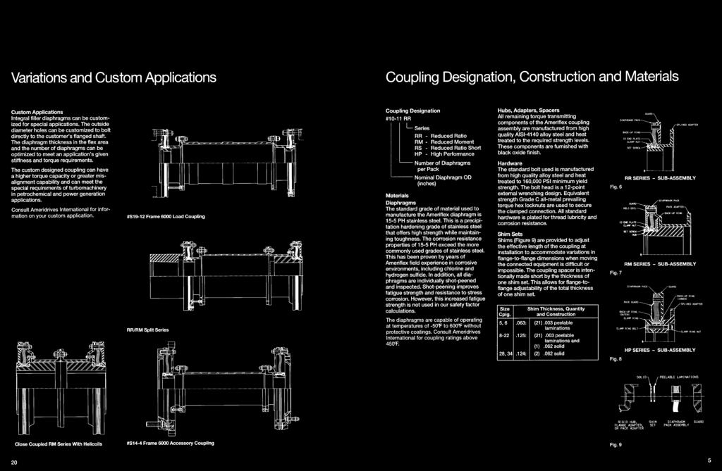
4 Diaphragm Couplings Series Description RR Series (Reduced Ratio) The Reduced Ratio design (Figure 2) offers high toque and large bore capacity, with a light weight, low moment assembly. Large axial travel capacity is maintained. Torque is transmitted from the pack to the spline adapter by a major diameter interference fit spline. The inside diameter of the pack is tightly clamped by a high strength clamp nut. RM Series (Reduced Moment) The reduced Moment design (Figure 3) provides a large bore and high torque capacity with the lowest overhung moment. Large axial travel capacity is maintained. Torque is transmitted from the hub to pack by a major diameter interference fit spline. The inside diameter of the pack is tightly clamped by a high strength clamp nut. Locking helicoils in the guards are now a standard feature, which further reduces windage and horsepower loss. RS Series (Reduced Ratio Short) The Reduced Ratio Short design (Figure 4) maintains the high torque to bore ratio and the large axial travel capacity of the RR Series with a one piece center section. Most commonly used for short shaft-to-shaft applications and gear coupling retrofits with high torsional stiffness. Torque is transmitted from the pack to the center shaft by a maior diameter interference fit spline. The inside diameter of the pack is tightly clamped by a high strength clamp nut. Locking helicoils in the guards are now a standard feature. Fig. 2 Fig. 3 Fig. 4 HP Series (High Performance) The original High Performance design (Figure 5) is used where very large axial travel capacity and the lowest stiffnesses are desired. The pack transmits torque to the spline adapter through a major diameter interference fit spline. The inside diameter of the pack is tightly clamped by the clamp ring bolts. In accordance with our established policy to constantly improve our products, the specifications contained herein are subject to change without notice. Fig. 5 4 Ameridrives Couplings P-1821-AC 10/09
5 Coupling Designation Construction and Materials Hubs, Adapters, Spacers All remaining torque transmitting components of the Ameriflex coupling assembly are manufactured from high quality AISI-4140 alloy steel and heat treated to the required strength levels. These components are furnished with black oxide finish. Materials Diaphragms The standardd grade of material used to manufacture the Ameriflex diaphragm is 15-5 PH stainless steel. This is a precipitation hardening grade of stainless steel that offers high strength while maintaining toughness. The corrosion resistance properties of 15-5 PH exceed the more commonly used grades of stainless steel. This has been proven by years of Ameriflex field experience in corrosive environments, including chlorine and hydrogen sulfide. In addition, all diaphragms are individually shot-peened and inspected. Shot-peening improves fatigue strength and resistance to stress corrosion. However, this increased fatigue strength is not used in our safety factor calculations. The diaphragms are capable of operating at temperatures of -50ºF (-45ºC) to 600ºF (315ºC) without protective coatings. Consult Ameridrives Couplings for coupling ratings above 450ºF (232ºC). Size Cplg. Hardware The standard bolt used is manufactured from high quality alloy steel and heat treated 160,000 PSI minimum yield strength. The bolt head is a 12-point external wrenching design. Equivalent strength Grade C all-metal prevailing torque hex locknuts are used to secure the clamped connection. All standard hardware is plated for thread lubricity and corrosion resistance. Shim Sets Shims (Figure 9) are provided to adjust the effective length of the coupling at installation to accommodate variations in flange-to-flange dimensions when moving the connected equipment is difficult or impossible. The coupling spacer is intentionally made short by the thickness of one shim set. This allows for flange-to-flange adjustability of the total thickness of one shim set. Shim Thickness, Quantity and Construction in (mm) 5, (1.600) (.076) peelable laminations (3.175) (.076) peelable laminations and (1.575) solid 28, (3.150) (1.575) solid Fig. 6 Fig. 7 Fig.8 Fig.9 P-1821-AC 10/09 Ameridrives Couplings

.")

6 Multiple Convoluted Diaphragm Pack The heart of the Ameriflex multiple convoluted diaphragm coupling is the stainless steel diaphragm pack (Figure 10). The pack conisists of several thin, convoluted diaphragms. The R Series pack consists of diaphragms with the flexing area machined thinner than the ID and OD. The resulting integral fillers (Figure 11) maintain separation of the flex area. Construction of the HP Series has not changed, with uniform thickness diaphragms separated at the ID and OD by filler rings and segments (Figure 12). The new integral filler design optimizes the shape and thickness of the diaphragms. The separate filler rings and segments have been eliminated, reducing the number of components and manufacturing processes. It is the thin convoluted diaphragms in parallel that give Ameriflex couplings their flexibility while maintaining torque capacity. Stresses, moments and forces of a diaphragm increase with the third power of the thickness. The use of several thinner diaphragms produces substantially lower values than a single diaphragm coupling with equal flex element thickness. Lower forces can be achieved without sacrificing peak torque capability or relying on mechanical back-up systems. Mechanical back-up devices, which engage to transmit power in the event of transient peak torques, can increase the level of damaging forces transmitted to a system at the worst possible time. A major advantage in the use of the thin convoluted diaphragm is the reduction of undesirable moments and forces transmitted to the bearings of the connected equipment. The convoluted form permits accurate prediction of those moments and forces. All styles of Ameriflex diaphragm packs have a constant axial stiffness with a single axial natural frequency. The unrolling action of the convolutions results in the diaphragm's large axial capacity and low sresses (Figure 13). Disc and contour diaphragms accommodate axial motion by pure deformation of material. In fact, once axial motion in a disc or contour diaphragm exceeds approximately one-half of the material thickness, stiffness and stresses become non-linear and increase exponentially. Therefore, predicting the axial force upon rotating equipment is very difficult for couplings that have a non-linear stiffness. A comparison of force versus axial travel of disc, contour diaphragm, and convoluted diaphragm couplings in Figure 14 demonstrates the stiffness variations. The convolution provides for a constant stiffness over a larger range of axial travel than does a disc or contoured diaphragm. The multiple convoluted diaphragm coupling has a distinct advantage over gear couplings in axial force and misalignment moment predictability. Fig. 11 Fig. 12 Fig. 13 Fig Ameridrives Couplings P-1821-AC 10/09


7 Safety Feature Multiple separated diaphragms provide an additional safety feature. The stresses in each diaphragmsin a pack are not equal due to the offset stress as shown in Figure 15. Therefore, if a fatigue failure was to occur due to overmisalignment, the outer diaphragm will fail first. Since the diaphragm flex areas are separated, one failed diaphragm will not necessitate the next to fail. The next diaphragm will have a lower combined alternating stress than the first, due to a lower offset stress. If machinery operations continue and the next outermost diaphragms continue to fail, the decreasing stress effect would continue until approximately one-half of the diaphragms have failed. Then the torque component of stress would cause the remaining diaphragms to fail in torsion. As a failed diaphragm continues to operate, cracks can develop into broken pieces. These will centrifuge and be caught in the guard. Most turbomachinery today incorporates vibration monitoring equipment designed to detect any unbalance by such a failed diaphragm. A total failure could also be prevented by inspection of the coupling, at normal maintenance periods, for cracks or distress areas in the outer diaphragm of the pack. Design Variables Steady state stresses have a definite relationship to each other. A decrease in a steady state stress, such as shear stress due to toque, allows for an increase in another steady state stress, such as axial stress due to equipment shaft movement, or centrifugal stress due to speed. Curves are provided for Series RR/RM/RS Ameriflex with the standard number of diaphragms, to define this relationship and assist the user in coupling selection process. It is also possible to vary the number of diaphragms per pack to suit special applications. Consult Ameridrives Couplings for ratings. Ameriflex Diaphragm Stress Analysis The Ameriflex multiple convoluted diaphragm is designed for infinite life based on the constant life diagram. Figure 16 shows typical results for the RR Series. Mean stresses (torsional, axial and centrifugal) are induced by steady state torsional loading, steady state axial deflections and coupling rotation. Alternating stresses (torsional, axial, flexure and offset) are a result of alternating torsional loading, cyclic axial deflections, and equipment misalignment or offset The design analysis for the Ameriflex diaphragm begins with calculating the directional stresses (radial, tangential and shear) for each of the load conditions described above. The actual stress equations are derived from finite element analysis (FEA). The strong correlation of FEA to strain gage testing (Figure 17) confirms that a two-dimensional analysis is appropriate for the diaphragm configuration. These directional stresses are combined to obtain the maximum and minimum principle stress for both the mean and alternating conditions. The von-mises or distortion energy theory is then used to obtain the combined mean and alternating stresses. Finally, these combined stresses are used to calculate the combined constant life safety factor as shown in Figure 16. The minimum cyclic safety factor for the alternating stresses is 2.0. Fig. 16 Fig. 17 Fig. 15 P-1821-AC 10/09 Ameridrives Couplings
8 Coupling Selection Step 1 - Selection Toque Calculate selection toque (T) from: T = T = HP x x SF RPM kw x 9549 x SF RPM SF = Service factor from chart (Page 9, Figure 19) NOTE: For API-671, applications use a 1.75 SF unless othenvise specified. CAUTION: Generator short circuit, compressor surge, electric motor starts and other applications can result in single cycle peak torques. Synchronous motors and reciprocating engines can exhibit high multiple cycle peak torques. It is important that these peak toques be considered when selecting a high performance coupling. We will assume a peak torque equal to 7 x normal operating torque for generator drives or synchronous motor drives unless othewise specified. Step 3 - Coupling Series Selection The following guidelines are suggested to assist in initial selection of the coupling series: RR Series - Should be the initial selection unless torque requirement is greater than a size 16 rating or the rotor dynamic concerns dictate a Reduced Moment (RM) design. RS Series - Should be selected if distance between shaft ends is less than the minimum for RR selection. The HP series short shaft-toshaft design will be provided for sizes 19 and larger. RM Series - Ideal selection if low overhung moment is required. HP Series - Select if axial travel or torque capacities of R Series design does not satisfy the requirements of the application. This series is also appropriate when minimal axial or bending stiffness is required. Step 2 - Axial Travel Requirements It is important to identify the movement of the drive and driven equipment shaft ends relative to a reference point, with the negative direction being toward the bearing and positive being away from the bearing. Shaft end movement occurs as a result of thermal changes in housing and shafts as well as fluid thrust. Axial travel requirements should be evaluated at start-up, transient operating conditions, shut down and normal operation. Ameridrives Couplings recommends installing high performance dry couplings with pre-stretch to reduce axial forces during operation. Where application conditions allow, the coupling should be installed with pre-stretch equal to the thermal growth from cold to hot normal operation. 8 Ameridrives Couplings P-1821-AC 10/09

9 Step 4 - Coupling Size Selection The initial selection is determined by choosing a continuous torque rating value that is equal to or greater than the calculated selection torque value. See pages for initial selection based on torque and axial travel requirements. Graphs are provided for the R Series couplings to permit selection of maximum torque capacity based on application axial requirements. See example. Step 5 Check bore, peak torque, misalignment and speed capacities and envelope restrictions to confirm initial selection. Contact Ameridrives Couplings: 1. If speed or misalignment requirements exceed catalog values. 2. If reduced axial or bending stiffness is required. See page 19 for special retrofit considerations. For assistance in selection, fill out and return pages 22 and 23 with your specific application requirements. Step 4 Example 35,000 HP (26,100 kw) gas turbine driving centrifugal compressor at 5000 RPM, API-671 applies, axial travel requirements is inches ( mm). T = T = 35,000 x 63,025 x ,000 26,100 x 9,549 x , ,056 = in.lb. = 87,230 Nm Fig. 18 From table on page 10, select size 14-12RR, then confirm axial travel and torque capacity from graph on page 11; see Figure 18. Note: Coupling torque rating will be 850,000 in.lb. (96,037Nm) Total axial capacity is.380 in. (9,652 mm) NOTE: Service Factors applied incorrectly will increase coupling size and weight unnecessarily. If coupling selection with Service Factor is too heavy or large, consult Ameridrives Couplings. Factors should be applied to normal operating torques only. Fig. 19 P-1821-AC 10/09 Ameridrives Couplings
10 RR Series Engineering Data Coupling Data - RR Series (Reduced Ratio) Half Coupling 5 Spacer Tube/in. (mm) KT KT Max. Continuous Peak Torque WR 2 In.Lb./ Wt. WR 2 In.Lb. Torque Rating Rating Rated Wt. Lb.In 2 Rad. x 10 6 Lb. Lb.Inc. Rad. x 10 6 Coupling In. Lb. x 1000 In. Lb. x 1000 Speed Lb. (kgm 2 x Y (kg-mm/rad. (kg x (kgm2 x (kg-mm/rad. Size (Nm x 1000) (Nm x 1000) RPM (kg) E-02) C.G. x E + 06) E-03) E-05) x E + 06) ,000 (6.41) (9.60) (5.26) (1.38) (-7.11) (38.25) (5.36) (1.15) (11,673.40) ,000 (10.54) (15.82) (7.85) (2.69) (-2.03) (72.93) (7.14) (2.30) (23,428.73) ,000 (19.55) (29.38) (17.24) (9.60) (6.10) (181.57) (12.50) (5.76) (55,027.96) ,000 (37.40) (56.04) (29.12) (24.79) (1.27) (389.42) (17.86) (13.83) (143,273.46) , , ,000 (72.31) (108.47) (48.94) (57.94) (11.43) (774.23) (28.57) (31.11) (323,200.03) 900 1, , , ,000 (101.69) (152.53) (67.40) (106.43) (2.79) (1,223.56) (37.50) (53.00) (545,729.09) 1,400 2, , , ,000 (158.18) (237.27) (89.86) (177.43) (11.43) (1,944.44) (53.57) (103.69) (1,073,700.81) 4,000 9, , , ,000 (451.94) (1,016.86) (284.99) (1,006.74) (-27.94) (6,626.10) (139.29) (362.92) (3,737,980.19) 1 All ratings at.25º misalignment. Higher misalignments available; consult Ameridrives Couplings. 2 Peak torque rating is at maximum axial travel rating. 3 For axial travel rating, see axial travel vs. continous torque ratings curve. 4 Higher speeds available. Consult Ameridrives Couplings for torque capacities at higher than rated speed. 5 Weight, WR 2 and KT based on J=18 inch SH-SH (457.2mm or minimum SH-SH, whichever is greater), and nominal bores. 6 Torque applicable up to rated axial travel of.200 inches (5.080mm). 10 Ameridrives Couplings P-1821-AC 10/09
 (Nm/Degree) 5 6 8 10 12 14 16 5.97 4.56 5.00 3.50 3.69 2.00 3.25 2.44 7.50 22.")
 (112.78) (117.60) (63.50) (95.25) (76.96) (190.50) (611.12) (210) (14) 8.97 7.25 6.94 5.09 5.38 3.50 5.00 4.19 8.56 26.38 2,200 440 (227.84) (184.15) (176.28) (129.29) (136.65) (88.90) (127.")
 (298) (45) 12.94 10.62 10.94 8.00 8.44 5.00 7.50 6.03 11.38 30.06 2,300 880 (328.68) (269.75) (277.88) (203.20) (214.38) (127.00) (190.50) (153.16) (289.05) (763.52) (403) (99) 14.75 12.12 12.")
11 Dimensions inches (mm) Coupling Data - RR Series (Reduced Ratio) Barrel Bore Bore Shaft-to- 7 Stiffness per Diaphragm 8 Coupling Dia. Flange Spacer Spacer Dia. Dia. Shaft Shaft Coupling Axial Stiffness Bending Stiffness Coupling O.D. B Dia. I.D. O.D. F F Length J Length Lb.In. In.Lb./Degree Size A Max. C D E Nominal Max. G Min. L (N/mm) (Nm/Degree) , (151.64) (115.82) (127.00) (88.90) (93.73) (50.80) (82.55) (61.98) (190.50) (581.15) (219) (11) , (176.28) (138.18) (150.88) (112.78) (117.60) (63.50) (95.25) (76.96) (190.50) (611.12) (210) (14) , (227.84) (184.15) (176.28) (129.29) (136.65) (88.90) (127.00) (106.43) (217.42) (670.05) (385) (50) , (277.88) (215.90) (227.84) (172.97) (181.10) (101.60) (152.40) (120.65) (258.83) (698.50) (298) (45) , (328.68) (269.75) (277.88) (203.20) (214.38) (127.00) (190.50) (153.16) (289.05) (763.52) (403) (99) , (374.65) (307.85) (306.32) (231.90) (244.60) (139.70) (215.90) (153.16) (341.38) (763.52) (385) (107) ,800 2,550 (430.28) (355.60) (347.73) (270.00) (285.75) (152.40) (254.00) (183.99) (347.73) (823.98) (665) (288) ,000 4,046 (568.45) (479.55) (504.95) (304.80) (339.85) (228.60) (342.90) (276.35) (587.25) (1,139.95) (876) (457) 22 7 Coupling length based on J = 18 inch SH-SH (457.2mm or minimum SH-SH, whichever is greater). 8 Coupling Axial Stiffness lb.in. (N/mm) = No. of Diaphragms x Diaphragm Axial Stiffness. 2 Coupling Bending Stiffness in.lb. (Nm)/Degree = No. of Diaphragms x Diaphragm Bending Stiffness. P-1821-AC 10/09 Ameridrives Couplings
12 RM Series Engineering Data Coupling Data - RM Series (Reduced Moment) Half Coupling 5 Spacer Tube/in. (mm) KT KT Max. Continuous Peak Torque WR 2 In.Lb./ Wt. WR 2 In.Lb. Torque Rating Rating Rated Wt. Lb.In 2 Rad. x 10 6 Lb. Lb.Inc. Rad. x 10 6 Coupling In. Lb. x 1000 In. Lb. x 1000 Speed Lb. (kgm 2 x Y (kg-mm/rad. (kg x (kgm2 x (kg-mm/rad. Size (Nm x 1000) (Nm x 1000) RPM (kg) E-02) C.G. x E + 06) E-03) E-05) x E + 06) ,000 (4.89) (7.34) (4.63) (1.17) (42.16) (36.98) (5.36) (1.15) (11,673.40) ,000 (8.67) (12.99) (7.17) (2.49) (54.10) (65.79) (7.14) (2.30) (23,428.73) ,000 (18.76) (28.25) (14.02) (7.64) (70.36) (143.55) (12.50) (5.76) (55,027.96) ,000 (32.77) (49.15) (24.95) (20.69) (83.57) (328.13) (17.86) (13.83) (143,273.46) , , ,000 (58.41) (87.56) (41.78) (48.17) (95.00) (623.99) (28.57) (31.11) (323,200.03) 750 1, , , ,000 (84.74) (127.11) (57.65) (88.67) (109.73) (1,040.25) (37.50) (53.00) (545,729.09) 1,200 1, , , ,000 (135.58) (203.37) (90.45) (172.28) (146.30) (1,619.77) (53.57) (103.69) (1,073,700.81) 4,000 9, , , ,000 (451.94) (1,016.86) (252.84) (927.47) ( ) (5,180.41) (139.29) (362.92) (3,737,980.19) 1 All ratings at.25º misalignment. Higher misalignments available; consult Ameridrives Couplings. 2 Peak torque rating is at maximum axial travel rating. 3 For axial travel rating, see axial travel vs. continous torque ratings curve. 4 Higher speeds available. Consult Ameridrives Couplings for torque capacities at higher than rated speed. 5 Weight, WR 2 and KT based on J=18 inch SH-SH (457.2mm or minimum SH-SH, whichever is greater), and nominal bores. 6 Torque applicable up to rated axial travel of.200 inches (5.080mm). 12 Ameridrives Couplings P-1821-AC 10/09
 (Nm/Degree) 5 6 8 10 12 14 16 22 6.94 3.83 5.94 4.44 4.63 2.50 3.03 4.62 24.06 1,200 120 (176.28) (97.28) (150.88) (112.78) (117.60) (63.")
 (152.15) (227.84) (172.97) (181.10) (101.60) (120.65) (112.78) (698.50) (298) (45) 12.94 7.25 10.94 8.00 8.44 4.50 5.31 6.19 28.62 2,300 880 (328.")
13 Dimensions inches (mm) Barrel Bore Shaft-to- 7 Stiffness per Diaphragm 8 Coupling Dia. Flange Spacer Spacer Dia. Shaft Shaft Coupling Axial Stiffness Bending Stiffness Coupling O.D. B Dia. I.D. O.D. F Length J Length Lb.In. In.Lb./Degree Size A Max. C D E Max. G Min. L (N/mm) (Nm/Degree) , (176.28) (97.28) (150.88) (112.78) (117.60) (63.50) (76.96) (117.35) (611.12) (210) (14) , (227.84) (122.94) (176.28) (129.29) (136.65) (82.55) (91.19) (104.65) (639.57) (385) (50) , (277.88) (152.15) (227.84) (172.97) (181.10) (101.60) (120.65) (112.78) (698.50) (298) (45) , (328.68) (184.15) (277.88) (203.20) (214.38) (114.30) (134.87) (157.23) (726.95) (403) (99) , (374.65) (206.25) (306.32) (231.90) (244.60) (139.70) (153.16) (168.15) (763.52) (385) (107) ,800 2,550 (430.28) (247.65) (347.73) (270.00) (285.75) (165.10) (203.20) (220.73) (863.60) (665) (288) ,000 4,046 (568.45) (339.85) (504.95) (304.80) (339.85) (228.60) (276.35) (276.35) (587.25) (876) (457) , (151.64) (82.55) (127.00) (88.90) (93.73) (57.15) (61.98) (98.55) (581.15) (219) (11) 7 Coupling length based on J = 18 inch SH-SH (457.2mm or minimum SH-SH, whichever is greater). 8 Coupling Axial Stiffness lb.in. (N/mm) = No. of Diaphragms 2 x Diaphragm Axial Stiffness. Coupling Bending Stiffness in.lb. (Nm)/Degree = No. of Diaphragms x Diaphragm Bending Stiffness. P-1821-AC 10/09 Ameridrives Couplings
14 RS Series Engineering Data Coupling Data - RS Series (Reduced Short) Half Coupling 5 Spacer Tube/in. (mm) KT KT Max. Continuous Peak Torque WR 2 In.Lb./ Wt. WR 2 In.Lb. Torque Rating Rating Rated Wt. Lb.In 2 Rad. x 10 6 Lb. Lb.Inc. Rad. x 10 6 Coupling In. Lb. x 1000 In. Lb. x 1000 Speed Lb. (kgm 2 x Y (kg-mm/rad. (kg x (kgm2 x (kg-mm/rad. Size (Nm x 1000) (Nm x 1000) RPM (kg) E-02) C.G. x E + 06) E-03) E-05) x E + 06) ,000 (6.41) (9.60) (5.13) (1.26) (-2.03) (29.84) (7.14) (1.15) (7,693.50) ,000 (10.54) (15.82) (8.03) (2.46) (1.02) (65.79) (10.71) (2.30) (18,167.07) ,000 (19.55) (29.38) (16.74) (8.81) (10.67) (170.17) (17.86) (4.61) (47,199.85) ,000 (37.40) (56.04) (27.22) (21.83) (8.64) (338.03) (26.79) (9.22) (100,170.56) , ,000 (72.31) (108.47) (45.59) (51.83) (20.32) (687.70) (37.50) (19.59) (200,818.12) 900 1, , , ,000 (101.69) (152.53) (60.87) (108.57) (15.24) (1,051.08) (48.22) (32.26) (338,232.93) 1,400 2, , , ,000 (158.18) (237.27) (82.55) (158.70) (22.35) (1,794.32) (66.07) (67.98) (696,420.97) 4,000 9, , , ,000 (451.94) (1,016.86) (252.26) (843.12) (-42.93) (6,964.36) (171.44) (309.92) (3,209,066.17) 1 All ratings at.25º misalignment. Higher misalignments available; consult Ameridrives Couplings. 2 Peak torque rating is at maximum axial travel rating. 3 For axial travel rating, see axial travel vs. continous torque ratings curve. 4 Higher speeds available. Consult Ameridrives Couplings for torque capacities at higher than rated speed. 5 Weight, WR 2 and KT based on J=18 inch SH-SH (457.2mm or minimum SH-SH, whichever is greater), and nominal bores. 6 Torque applicable up to rated axial travel of.200 inches (5.080mm). 14 Ameridrives Couplings P-1821-AC 10/09
 (Nm/Degree) 5 6 8 10 12 14 16 22 10.94 8.50 5.83 4.38 5.09 4.00 4.75 4.50 27.50 1,700 400 (277.")
 (127.00) (190.50) (153.16) (127.00) (763.52) (403) (99) 14.75 12.12 7.83 6.00 6.94 5.50 8.50 6.03 5.50 30.06 2,200 950 (374.65) (307.85) (198.88) (152.40) (176.28) (139.70) (215.90) (153.16) (139.")
15 Dimensions inches (mm) Barrel Bore Bore Shaft-to- 7 Stiffness per Diaphragm 8 Coupling Dia. Shoulder Spacer Spacer Dia. Dia. Shaft Shaft Coupling Axial Stiffness Bending Stiffness Coupling O.D. B Dia. I.D. O.D. F F Length J Length Lb.In. In.Lb./Degree Size A Max. C D E Nominal Max. G Min. L (N/mm) (Nm/Degree) , (277.88) (215.90) (148.08) (111.25) (129.29) (101.60) (152.40) (120.65) (114.30) (698.50) (298) (45) , (328.68) (269.75) (177.29) (134.87) (155.45) (127.00) (190.50) (153.16) (127.00) (763.52) (403) (99) , (374.65) (307.85) (198.88) (152.40) (176.28) (139.70) (215.90) (153.16) (139.70) (763.52) (385) (107) ,800 2,550 (430.28) (355.60) (241.30) (187.45) (214.38) (152.40) (254.00) (183.39) (139.70) (823.98) (665) (288) ,000 4,046 (568.45) (479.55) (339.85) (241.30) (293.62) (228.60) (342.90) (276.35) (190.50) (1,009.90) (876) (457) ,250 1,200 2, (151.64) (176.28) (227.84) (115.82) (138.18) (184.15) (83.57) (98.04) (126.24) (63.50) (72.14) (93.47) (71.37) (84.07) (107.95) (50.80) (63.50) (88.90) (82.55) (95.25) (127.00) (61.98) (76.96) (106.43) (76.20) (77.72) (95.25) (581.15) (611.12) (670.05) (219) (210) (385) (11) (14) (50) 7 Coupling length based on J = 18 inch SH-SH (457.2mm or minimum SH-SH, whichever is greater). 8 Coupling Axial Stiffness lb.in. (N/mm) = No. of Diaphragms 2 x Diaphragm Axial Stiffness. Coupling Bending Stiffness in.lb. (Nm)/Degree = No. of Diaphragms x Diaphragm Bending Stiffness. P-1821-AC 10/09 Ameridrives Couplings
16 HP Series Engineering Data Coupling Data - HP Series (High Performance) Half Coupling 3 Spacer Tube/in. (mm) Coupling KT KT Max. Continuous Peak Torque Axial WR 2 In.Lb./ Wt. WR 2 In.Lb. Torque Rating Rating Travel Rated Wt. Lb.In 2 Rad. x 10 6 Lb. Lb.Inc. Rad. x 10 6 Coupling In. Lb. x 1000 In. Lb. x 1000 ( + - In.) Speed Lb. (kgm 2 x Y (kg-mm/rad. (kg x (kgm2 x (kg-mm/rad. Size (Nm x 1000) (Nm x 1000) ( + - mm.) RPM (kg) E-02) C.G. x E + 06) E-03) E-05) x E + 06) ,000 (3.39) (5.08) (2.54) (5.62) (1.17) (-11.43) (19.59) (5.36) (0.58) (5,589.42) ,000 (7.23) (10.85) (3.18) (8.75) (2.43) (-8.89) (41.94) (7.14) (1.15) (12,176.74) ,000 (18.08) (28.25) (3.81) (20.41) (9.74) (-6.60) (128.00) (16.07) (3.46) (38,315.31) ,000 (33.90) (50.84) (4.75) (33.25) (25.75) (-8.64) (285.61) (21.43) (9.22) (95,833.64) , ,000 (56.49) (84.74) (5.49) (54.79) (57.06) (-1.52) (501.29) (32.14) (17.28) (177,169.91) 660 1, , ,000 (74.57) (112.98) (6.99) (74.43) (106.08) (-10.16) (797.73) (35.72) (25.35) (262,284.16) 675 1, , , ,000 (76.26) (186.42) (7.92) (104.33) (187.90) (-11.18) (1,183.58) (44.64) (39.17) (408,410.85) 1,400 3, , , ,000 (158.18) (338.95) (9.53) (185.43) (465.77) (-18.29) (1,932.23) (75.00) (76.04) (781,263.06) 2,700 4, , , ,000 (305.06) (463.24) (10.41) (278.91) (933.93) (10.67) (3,834.27) (98.22) (157.84) (1,626,371.32) 5,300 8, , , , ,800 (598.82) (903.88) (15.88) (595.70) (3,404.89) (16.51) (8,489.43) (157.15) (382.51) (3,952,836.23) 6,000 15, , , , , ,000 (677.91) (1,694.77) (22.23) (966.65) (7,496.61) (10.41) (13,221.44) (233.94) (868.70) (8,969,426.46) 1 All ratings at.25º misalignment. Higher misalignments available; consult Ameridrives Couplings. 2 Higher speeds available. Consult Ameridrives Couplings for torque capacities at higher than rated speed. 3 Weight, WR 2 and KT based on J=18 inch SH-SH (457.2mm or minimum SH-SH, whichever is greater), and nominal bores. 4 Peak torque rating is at maximum axial travel rating. 16 Ameridrives Couplings P-1821-AC 10/09
 (Nm/Degree) 5 6 8 10 12 14 16 19 22 28 34 10.94 8.50 7.38 5.00 5.50 4.00 6.00 4.75 11.12 27.")
 (209.55) (138.18) (155.70) (127.00) (190.50) (153.16) (335.03) (763.52) (263) (73) 14.75 12.12 9.25 6.25 6.94 5.50 8.50 6.03 14.50 30.06 1,400 650 (374.65) (307.85) (234.95) (158.75) (176.")
17 Balance Dimensions inches (mm) Barrel Bore Bore Shaft-to- 5 Stiffness per Diaphragm 6 Coupling Dia. Flange Spacer Spacer Dia. Dia. Shaft Shaft Coupling Axial Stiffness Bending Stiffness Coupling O.D. B Dia. I.D. O.D. F F Length J Length Lb.In. In.Lb./Degree Size A Max. C D E Nominal Max. G Min. L (N/mm) (Nm/Degree) , (277.88) (215.90) (187.45) (127.00) (139.70) (101.60) (152.40) (120.65) (282.45) (698.50) (175) (26) , (328.68) (269.75) (209.55) (138.18) (155.70) (127.00) (190.50) (153.16) (335.03) (763.52) (263) (73) , (374.65) (307.85) (234.95) (158.75) (176.28) (139.70) (215.90) (153.16) (368.30) (763.52) (245) (73) ,000 2,250 (430.28) (355.60) (285.75) (179.32) (198.37) (152.40) (254.00) (183.99) (420.62) (823.98) (525) (254) ,700 2,240 (504.95) (406.40) (309.63) (185.67) (215.90) (177.80) (285.75) (220.73) (501.65) (943.10) (473) (253) ,500 2,300 (581.15) (479.55) (358.65) (236.47) (268.22) (228.60) (342.90) (276.35) (520.70) (1,073.40) (438) (260) ,300 2,417 (736.60) (584.20) (469.90) (290.58) (331.72) (304.80) (412.75) (352.55) (647.70) (1,352.80) (403) (273) ,500 7,308 (874.78) (749.30) (558.80) (360.43) (409.70) (355.60) (533.40) (406.40) (876.30) (1,689.10) (438) (826) , (151.64) (176.28) (227.84) (115.82) (138.18) (184.15) (101.60) (123.95) (142.75) (61.98) (74.68) (87.38) (68.33) (82.55) (101.60) (50.80) (63.50) (88.90) (82.55) (95.25) (127.00) (61.98) (76.96) (106.43) (184.45) (203.20) (250.95) (581.15) (611.12) (670.05) (140) (123) (193) (8) (8) (26) 5 Coupling length based on J = 18 inch SH-SH (457.2mm or minimum SH-SH, whichever is greater). 6 Coupling Axial Stiffness lb.in. (N/mm) = No. of Diaphragms x Diaphragm Axial Stiffness. 2 Coupling Bending Stiffness in.lb. (Nm)/Degree = No. of Diaphragms x Diaphragm Bending Stiffness. Amerifiex couplings are designed to achieve the low levels of potential unbalance necessary to meet the increasing demands of high perfomance equipment. Turbomachinery vibration levels can be dramatically affected by coupling unbalance. Fastneners are weight balanced in sets to API-671 standards. Component balanced parts of a coupling assembly are interchangeable with new parts from identical couplings. Trim balance holes are provided on request. Major components are matchmarked for identical reassembly. Amerifiex couplings can be provided complying to any API-671 balance option. In addition, any options for residual unbalance check or balance machine sensitivity check can be provided. For non-api couplings, component balancing will be provided unless otherwise specified. All components are machined to stringent tolerances and balanced to the lowest possible levels of residual unbalance. The use of light interference fits allows Amerifiex couplings to be repeatably assembled without changing component mass eccentricities which helps maintain superior levels of balance. All Ameriflex components and assemblies are balanced to the residual unbalance levels of API-671. All rigid hubs, subassemblies, and other short components are single plane balanced. Spacers and complete couplings are two plane balanced. All balancing is done on precise soft bearing balancing equipment, with the latest advancements in modern computer technologies. P-1821-AC 10/09 Ameridrives Couplings
18 Speed Limits Speed Limits Diaphragm couplings are an integral part of a system. If a system is very rigid then the maximum speed might be increased. If the system is soft and has a long shaft overhang, then it may be necessary to decrease speed limits. Whenever possible, a detailed system lateral critical speed analysis should be performed by the user. Ameridrives Couplings recommends the coupling lateral critical speed be a minimum of 1.5 times the maximum continuous operating speed. Axial Natural Frequency - (ANF) Metallic membrane couplings typically rely on deformation of the membrane to accommodate angular and axial misalignment between the shaft ends of the mating equipment. This deformation is accompanied by a resultant force attempting to restore the membrane to its undeformed shape. Under certain conditions, the coupling may resonate along the axis of rotation in what is commonly referred to as the coupling's axial natural frequency (ANF). Inherent in the design and characteristics of metallic membrane couplings is the deformation and stiffness when axially deflected. For small deflections this stiffness is constant for any type of membrane coupling. As deflections become increasingly larger, this stiffness may remain constant or may become increasingly non-linear, depending upon the design of the coupling. Forces that are generated from this stiffness must be counteracted by the thrust bearings. As a coupling rotates, there may be axial excitations such as runout in a thrust bearing. This may introduce a resonance in the coupling where the weight supported by the membranes axially vibrates at the ANF. This resonance is dependent on the magnitude of the axial excitation and any inherent damping that may be present throughout the train. It is very difficult to predict if a system will have a significant excitation, what the coupling response will be, and if this response is detrimental to the coupling itself. Any coupling resonating at an ANF will have additional cyclic axial stress which could affect the life of the coupling. Additionally, microscopic motion from frictional damping between adjacent laminations in nonseparated metallic membranes, such as disc type couplings, can accelerate wear. The Ameriflex coupling design provides separation of the flex area which prevents wear and provides a single ANF. For these reasons, it is best to avoid operating a coupling at its ANF. Ameridrives Couplings standard practice is to avoid and ANF at % away from the operating speed. The existence of any axial excitations should be noted when inquiring about a metallic membrane coupling. 18 Ameridrives Couplings P-1821-AC 10/09
19 Retrofit Applications When any High Performance coupling is selected to replace another type of coupling (Example: Diaphragm replacing Class I Gear or a competitor's coupling), it is recommended that a complete system analysis be done by the purchaser. This is necessary since many equipment manufacturers use couplings for tuning their systems. Therefore, indiscriminately changing a coupling may result in movement of a torsional or lateral critical into the operating speed range. When designing Ameriflex Couplings for retrofit applications, we attempt to match the weight, torsional stiffness, and overhung moment characteristics of the existing coupling. To properly select a coupling, the following information is required: 1. A drawing of the existing coupling providing the following data: a. Weight b. Torsional Stiffness c. Polar moment of inertia (WR 2 ) d. Centers of gravity e. Axial and bending stiffness for disc or diaphragm couplings f. Distance from journal bearing centerline to end of shaft g. Thermal growth 2. A drawing of the existing coupling guard 3. History of the existing coupling. a. Length of time in service b. Any problems experienced NOTE: Couplings are selected based on information supplied by the purchaser. Ameridrives Couplings will not be responsible for errors due to incomplete or inaccurate information. The application of the guidelines above are not a guarantee of the successful operation of any coupling in any system. It is the responsibilty of the purchaser to take the coupling characterisitics and determine their effect on the system. For assistance in selection, fill out and return pages 22 and 23 with your specific application requirements, including additional retrofit information. Additional Information Available Ameridrives Couplings maintains a reference libraty of information that is available to all of our customers. Please feel free to contact Ameridrives Couplings and request any of the following data sheets: P10-GI-6 Information Requirements For Selection of High Performance Couplings P10-GI-8 Diaphragm Pack Stresses P10-GI-9 Retrofit Criteria P10-GI-24 Heat Generation and Windage Loss Calculations P10-GI-47 Ameriflex Lateral Critical Speed Calculations P10-GI-78 Specifications for Ameriflex Compliance to API-671, Second Edition P10-GI-88 Exception to API-671, Second Edition G14-GI-8 Interface Connection Information Bending moment vs. misalignment and axial force vs. axial travel graphs and installation manuals are also available. P-1821-AC 10/09 Ameridrives Couplings
20 Variations and Custom Applications Custom Applications lntegral filler diaphragms can be customized for special applications. The outside diameter holes can be customized to bolt directly to the customer's flanged shaft. The diaphragm thickness in the flex area and the number of diaphragms can be optimized to meet an application's given stiffness and toque requirements. The custom designed coupling can have a higher toque capacity or greater misalignment capability and can meet the special requirements of turbomachinery in petromchemical and power generation applications. Consult Ameridrives Couplings for information on your custom application. 20 Ameridrives Couplings P-1821-AC 10/09


21 Custom Applications P-1821-AC 10/09 Ameridrives Couplings
22 Application Data 22 Ameridrives Couplings P-1821-AC 10/09
23 CAUTION: This product will be selected based on the information supplied to Ameridrives Couplings by the Purchaser. Complete and accurate information will helpt to minimize errors and misapplications. Further, it is the responsibility of the Purchaser to assure the interface connection between couplings and connected equipment (flanges, bolting, keys, hydraulic fits, etc.), are capable of handling anticipated loads. Ameridrives Couplings will not be responsible for errors due to inaccurate or incomplete information supplied to Ameridrives Couplings nor does Ameridrives Couplings assume responsibilty of the interface connection. For futher information and installation procedures, contact Ameridrives Couplings. P-1821-AC 10/09 Ameridrives Couplings

24 Altra Industrial Motion Ameridrives Couplings 1802 Pittsburgh Ave. Erie, PA Fax: An Altra Industrial Motion Company P-1821-AC (609-ADV) 10/09 Printed in U.S.A.
Ameriflex Diaphragm Couplings High Speed, High Performance Design
 A L T R A I N D U S T R I A L M O T I O N Ameriflex Diaphragm Couplings High Speed, High Performance Design P-1821-AC 7/12... Ameridrives Couplings 814-480-5000 1 Diaphragm Couplings Since its introduction
Maximum Performance Contoured Diaphragm Couplings
 Maximum Performance Contoured Diaphragm Couplings Goodrich Couplings offers: Best Balance Repeatability Lowest Weight Highest Reliability Ease of Installation Stainless Steel Diaphragms Goodrich Corporation
Retrofitting Gear Couplings with Diaphragm Couplings
 A l t r a I n d u s t r i a l M o t i o n Warner Electric Boston Gear TB Wood s Formsprag Clutch Retrofitting Gear Couplings with Diaphragm Couplings Wichita Clutch Marland Clutch Industrial Clutch Bauer
RM Flexible Disc Coupling
 RM Flexible isc RM Selection ata ontinuous ontinuous Half Torsional Torque ( lb-in x Weight WR HP/ (in-lbs ( lb-in/rad x rad 1 1 4 4...4. 4 1.4 1... 4 1.... 4. 11 1.1 1 1..4.4 4 1 11 1.1 1.4.4 1 1. 11
Retrofitting Turbomachinery with High Performance Flexible Dry Couplings
 A l t r a I n d u s t r i a l M o t i o n Warner Electric Boston Gear TB Wood s Formsprag Clutch Wichita Clutch Retrofitting Turbomachinery with High Performance Flexible Dry Couplings Marland Clutch Industrial
TYPE HSFE/HLFE/HTFE H SERIES HIGH PERFORMANCE COUPLINGS
 A High Strength Stainless Steel Flexible Membranes B Overload Collars C Flanged Connections D Shrouded bolts B C D A Product Description John Crane s HSFE/HLFE/HTFE s feature a factory assembled transmission
Couplings - Balancing Tutorial & New Developments in Gas Turbine Couplings by Joe Corcoran & Christian Wolford
 Couplings - Balancing Tutorial & New Developments in Gas Turbine Couplings by Joe Corcoran & Christian Wolford Joseph P. Corcoran Manager, Global Services and Training Kop-Flex, Regal- Beloit Hanover,
TLC. T Series Couplings. Product Description. Design Features
 TLC A Stainless Steel, Flexible Membranes B Overload Collars C Cartridge Transmission Unit D Anti-Fly Feature E Anti-Corrosion Treatment F Hubs with Puller Holes G Externally Wrenched Bolts H Large Shaft
AUTOFLEX DISC COUPLINGS
 AUTOFLEX DISC COUPLINGS Contents & Coupling Application Configurations Coupling Type Typical Application Series Page No Introduction - Disc Configuration 2 Coupling Selection 3 & 4 Service Factors High
TYPE HSRE/HLRE/HTRE H SERIES HIGH PERFORMANCE COUPLINGS
 A High Strength Stainless Steel Flexible Membranes B Overload Collars C Trim Balance Holes D Shrouded Bolts A C B D Product Description John Crane s Metastream HSRE/HLRE/HTRE reduced moment couplings use
RM Flexible Disc Coupling
 RM Flexible isc RM Selection ata apacity (kw/rpm 1 Torque (knm....6. (RPM (kg ( kgm.g. (MNm/rad (MNm/rad/m (kgm ( kgm. 1.. 6.... 1 1. 6 9. 1 6.. 9.1. 1 1. 6 1... 9.1. 6 1.... 1.1 6 1. 9. 1. 1.1 1. 6..
Altra High Performance
 A l t r a I n d u s t r i a l M o t i o n Altra High Performance Couplings Altra Couplings I High Performance Couplings AMERIDRIVES Ameriflex Diaphragm Coupling Since its introduction in 1971, the Ameriflex
A l t r a I n d u s t r i a l M o t i o n. Altra High Performance Couplings
 A l t r a I n d u s t r i a l M o t i o n Altra High Performance Couplings Altra Couplings I High Performance Couplings AMERIDRIVES Ameriflex Diaphragm Coupling Since its introduction in 1971, the Ameriflex
MEX (55) QRO (442) MTY (81) DIST. AUTORIZADO. Form. No.
 QRO (442) MTY (81) DIST. AUTORIZADO. Form. No.") R Form. No. 367-SH, 6/00 Ameriflex Installation and Maintenance Manual TABLE OF CONTENTS SECTION TITLE PAGE 1 Introduction...: 3 2 Description of Terminology...: 3 3 General Information...: 7 4 Coupling
R Form. No. 367-SH, 6/00 Ameriflex Installation and Maintenance Manual TABLE OF CONTENTS SECTION TITLE PAGE 1 Introduction...: 3 2 Description of Terminology...: 3 3 General Information...: 7 4 Coupling
M High Performance Power Transmission Couplings
 Engineered for Powerful Performance M High Performance Power Transmission Couplings Metastream High Performance Power Transmission Couplings High Performance Technology Metastream power transmission couplings
IDENTIFYING DISC COUPLING FAILURES COUPLING FUNDAMENTALS
 IDENTIFYING DISC COUPLING FAILURES While couplings are designed for infinite life, they must be operated within their intended design limits in order to achieve optimal performance. Due to installation
50 years of Reliable Field History
 Coupling Comments The No Maintenance, Easy Assembly, Resilient Coupling with High Angular Misalignment up to 10 degrees Center Assembly 70 Deg. Neoprene Rubber in Compression Grade 5 Bolts Steel Flanges
Diaphragm Couplings Versus Gear Couplings for Marine Applications
 A l t r a I n d u s t r i a l M o t i o n Warner Electric Boston Gear TB Wood s Formsprag Clutch Wichita Clutch Diaphragm Couplings Versus Gear Couplings for Marine Applications Marland Clutch Industrial
PRECISION BELLOWS COUPLINGS
 PRECISION BELLOWS COUPLINGS Bellows couplings are used where precise rotation, high speeds, and dynamic motion must be transmitted. They exhibit zero backlash and a high level of torsional stiffness, offering
Riverhawk Company 215 Clinton Road New Hartford NY (315) Free-Flex Flexural Pivot Engineering Data
 Free-Flex Flexural Pivot Engineering Data") Riverhawk Company 215 Clinton Road New Hartford NY (315)768-4937 Free-Flex Flexural Pivot Engineering Data PREFACE Patented Flexural Pivot A unique bearing concept for applications with limited angular
Riverhawk Company 215 Clinton Road New Hartford NY (315)768-4937 Free-Flex Flexural Pivot Engineering Data PREFACE Patented Flexural Pivot A unique bearing concept for applications with limited angular
Huco Dynatork Flexible Couplings
 Huco Dynatork Flexible Couplings Flexible Couplings The Company & Its Products Huco products are manufactured in Hertford, England, in a modern plant equipped with all necessary design, development, toolroom
MORFLEX COUPLINGS Double MORFLEX Series CC Hub and Block Assemblies Round steel flanges
 MORFLEX COUPLINGS The MORFLEX coupling should be installed where considerable dimensional misalignment may result, or is expected. It also cushions shock loads and absorbs vibration. The MORFLEX coupling
A l t r a I n d u s t r i a l M o t i o n. Altra High Performance Couplings
 A l t r a I n d u s t r i a l M o t i o n Altra High Performance Couplings Altra Couplings I High Performance Couplings AMERIDRIVES COUPLINGS Ameriflex Diaphragm Coupling Since its introduction in 1971,
TYPE TSC/TLC T SERIES METAL MEMBRANE COUPLINGS
 A Stainless Steel Flexible Discs B Overload Collars C Cartridge Transmission Unit D Anti-Fly Feature E Anti-Corrosion Treatment F Hubs with Puller Holes G Externally Wrenched Bolts H Large Shaft Diameters
EXPANSION JOINT SELECTION GUIDE
 EXPANSION JOINT SELECTION GUIDE The proper selection and application of an expansion joint is the determining factor in its operation and life. Improper selection and application will lead to problems
Disc Couplings 101. Ameridrives. Bauer Gear Motor. Bibby Turboflex. Boston Gear. Delroyd Worm Gear. Formsprag Clutch. Guardian Couplings.
 l t r a I n d u s t r i a l M o t i o n meridrives Bauer Gear Motor Bibby Turboflex Boston Gear Disc Couplings 101 Delroyd Worm Gear Formsprag Clutch Guardian Couplings Huco Industrial Clutch Inertia Dynamics
TYPE TSC/TLC T SERIES FLEXIBLE DISC COUPLINGS
 TYPE TSC/TLC A Stainless steel flexible discs B Overload collars C Cartridge transmission unit D Anti-fly feature E Anti-corrosion treatment F Hubs with API puller holes G Robust hub bolt H Large shaft
RFC SPECIALTY LOCKING DEVICES
 RINGFEDER Products are available from MARYLAND METRICS P.O. Box 261 Owings Mills, MD 21117 USA email: sales@mdmetric.com web: http://mdmetric.com phones: (410)358-3130 (800)638-1830 faxes: (410)358-3142
High Performance Gear
 JW High Performance Gear In This Section: FHS Type - High Speed Close Coupled FHSA Type - High Speed Standard FHSAA Type - High Speed Precision FHSPAA Type - High Speed Ultra Precision FHSMA Type - High
ISO INTERNATIONAL STANDARD
 INTERNATIONAL STANDARD ISO 14691 First edition 1999-11-01 Petroleum and natural gas industries Flexible couplings for mechanical power transmission General purpose applications Industries du pétrole et
DIST. AUTORIZADO MEX (55) QRO (442) MTY (81)
 QRO (442) MTY (81)") The Coupling For Today s Most Difficult Applications. The CD Coupling is a unique hybrid coupling, combining the best features found in both steel disc and elastomeric couplings. Through its new open arm
The Coupling For Today s Most Difficult Applications. The CD Coupling is a unique hybrid coupling, combining the best features found in both steel disc and elastomeric couplings. Through its new open arm
Why Choose Rexnord? 866-REXNORD/ (Within the U.S.) (Outside the U.S.)
 (Outside the U.S.)") 866-REXNORD/866-739-6673 (Within the U.S.) 44-643-366 (Outside the U.S.) www.rexnord.com Why Choose Rexnord? When it comes to providing highly engineered products that improve productivity and efficiency
866-REXNORD/866-739-6673 (Within the U.S.) 44-643-366 (Outside the U.S.) www.rexnord.com Why Choose Rexnord? When it comes to providing highly engineered products that improve productivity and efficiency
Troubleshooting Power Transmission Couplings
 Troubleshooting Power Transmission Couplings Introduction Power transmission couplings are used to connect two shafts that turn in the same direction on the same centerline. There are three principle types
Couplings and Collars
 Couplings and Collars Selection Guide The couplings featured in this catalogue have been carefully selected to accoodate varying degrees of shaft misalignment whilst offering minimum distortion of rotation.
Chapter 11. Keys, Couplings and Seals. Keys. Parallel Keys
 Chapter 11 Keys, Couplings and Seals Material taken for Keys A key is a machinery component that provides a torque transmitting link between two power-transmitting elements. The most common types of keys
Comparison Chart. extremely difficult. Finally, separated components can rarely be re-used.
 JAN 2014 Traditional Connections Why Go Keyless Keyed Bushing Systems Both QD and Taper-Lock bushing and weld-on hub systems are popular component mounting technologies. Yet both are ultimately keyed connections
TRANSLATION (OR LINEAR)
") 5) Load Bearing Mechanisms Load bearing mechanisms are the structural backbone of any linear / rotary motion system, and are a critical consideration. This section will introduce most of the more common
5) Load Bearing Mechanisms Load bearing mechanisms are the structural backbone of any linear / rotary motion system, and are a critical consideration. This section will introduce most of the more common
CD Couplings SERIES A1C. MTY (81) MEX (55) QRO (442) DIST.
 MEX (55) QRO (442) DIST.") CD Couplings SERIES A1C ZERO-MAX CD COUPLINGS SERIES A1C For today s most demanding servo motor and motion control applications. CD Couplings Series A1C are precise, robust, and available in sizes and
CD Couplings SERIES A1C ZERO-MAX CD COUPLINGS SERIES A1C For today s most demanding servo motor and motion control applications. CD Couplings Series A1C are precise, robust, and available in sizes and
PIP REEE003 Guidelines for General Purpose Non-Lubricated Flexible Couplings
 September 2016 Machinery PIP REEE003 Guidelines for General Purpose Non-Lubricated Flexible Couplings PURPOSE AND USE OF PROCESS INDUSTRY PRACTICES In an effort to minimize the cost of process industry
Torsiflex-i Disc Couplings for General Purpose Applications
 A l t r a I n d u s t r i a l M o t i o n Torsiflex-i Disc Couplings for General Purpose Applications Now Available With Torsi-Lock Hubs Altra Couplings I Torsiflex-i Disc Couplings for General Purpose
High performance metal disk coupling SERVOFLEX SFF (N)
") High performance metal disk coupling SERVOFLEX SFF (N) Best design for the latest servo motor SERVOFLEX for feed shaft which introduce the high precision clamp method Coupling outer diameter, lineup for
High performance metal disk coupling SERVOFLEX SFF (N) Best design for the latest servo motor SERVOFLEX for feed shaft which introduce the high precision clamp method Coupling outer diameter, lineup for
MAIN SHAFT SUPPORT FOR WIND TURBINE WITH A FIXED AND FLOATING BEARING CONFIGURATION
 Technical Paper MAIN SHAFT SUPPORT FOR WIND TURBINE WITH A FIXED AND FLOATING BEARING CONFIGURATION Tapered Double Inner Row Bearing Vs. Spherical Roller Bearing On The Fixed Position Laurentiu Ionescu,
CLASSIFICATION OF ROLLING-ELEMENT BEARINGS
 CLASSIFICATION OF ROLLING-ELEMENT BEARINGS Ball bearings can operate at higher speed in comparison to roller bearings because they have lower friction. In particular, the balls have less viscous resistance
TECHNICAL INFORMATION
 General Nomenclature Spherical Roller Bearings The spherical roller bearing is a combination radial and thrust bearing designed for taking misalignment under load When loads are heavy, alignment of housings
Air Champ RPM DPC-15T DPC-13T DPC-11T DPC-11T DPC-9T DPC-9T DPC-9T DPC-9T DPC-9T DPC-9T DPC-9T DPC-9T DPC-9T DPC-9T DPC-9T DPC-9T DPC-9T DPC-9T
 DUAL PLATE FRICTION CLUTCH SELECTION CHART Friction clutch recommendation is based upon air pressure of 50 psi, transmitted horsepower and speed. RPM 100 200 300 400 500 600 700 800 900 1000 1100 1200
High Performance Gear Couplings
 Overview -1 Overview Lovejoy High Speed and Engineered Special Gear Couplings The High Performance group of gear couplings consists of coupling designs that require additional engineering. While standard
Chapter 7. Shafts and Shaft Components
 Chapter 7 Shafts and Shaft Components 2 Chapter Outline Introduction Shaft Materials Shaft Layout Shaft Design for Stress Deflection Considerations Critical Speeds for Shafts Miscellaneous Shaft Components
Amerigear SF Spindle
 Amerigear SF Spindle Installation and Maintenance Manual Form No. 381-SH, 4/01 Spindle Installation and Maintenance Manual TABLE OF CONTENTS SECTION TITLE PAGE 1 Introduction...: 3 2 General Information...:
Trust but verify: the value of acceptance testing
 Trust but verify: the value of acceptance testing Les Miller, Dave VanLangevelde and Rick Burgess, Kaydon Bearings For many applications, the values and engineering data in bearing manufacturers catalogs
Rigid Couplings. P-1686-TBW 2/17... TB Wood s F7-1
 Rigid Couplings F7 F7-1 AVS Series Couplings AVS Series (Adjustable Vertical Spacer) Coupling used for vertical turbine pumps No flexible element Integral nut used for infinite adjustment of pump turbine
TORQUE LIMITER SERIES 600. Airjustor
 TORQUE LIMITER SERIES 600 Airjustor Quality and Autogard are synonymous with overload protection. The Company's reputation for high quality products is derived from over 40 years of design, innovation
Torque Limiter 320 Series Overview. Torque Limiter 320 Series
 Torque Limiter 0 Series Overview Torque Limiter 0 Series Torque Limiter 0 Series For more than 80 years, Autogard products have led the industry in overload protection with high-quality products, design
Sheet 1 Variable loading
 Sheet 1 Variable loading 1. Estimate S e for the following materials: a. AISI 1020 CD steel. b. AISI 1080 HR steel. c. 2024 T3 aluminum. d. AISI 4340 steel heat-treated to a tensile strength of 1700 MPa.
Interface Webinar Wednesday. with Keith Skidmore
 Interface Webinar Wednesday Torque 101 with Keith Skidmore www.interfaceforce.com 480 948 5555 Definitions What is a Torque Transducer? Rotary vs. Reaction Shaft vs. Flange Couplings Floating vs. Fixed
Thomas Disc Couplings Installation and Maintenance Series 52 Sizes with classical disc pack TM (Page 1 of 10) DANGER!
 DANGER!") Thomas Disc Couplings Installation and Maintenance Series 52 Sizes 125-925 with classical disc pack TM (Page 1 of 10) This is the Original Document in English Language Figure 1-1. General Information Thomas
Thomas Disc Couplings Installation and Maintenance Series 52 Sizes 125-925 with classical disc pack TM (Page 1 of 10) This is the Original Document in English Language Figure 1-1. General Information Thomas
Series 54 and S54 Resilient Couplings
 Series 54 and S54 Resilient s Bibby Transmissions Resilient s Bibby are the world originator of the resilient grid type shaft coupling, which is universally accepted by engineers to be one of the most
HTC/Flex Coupling Assembly HC-5981 Installation and Maintenance Instructions
 HTC/Flex Coupling Assembly HC-5981 Installation and Maintenance Instructions Riverhawk Document Number IM-301 Document No. IM-301 Created: 3/1/13 DML Contents: Section Description 1.0 General Description
INTRODUCTION SBPT DIAPHRAGM COUPLING: FEATURES APPLICATION
 INTRODUCTION SBPT is an ISO 9001: 2000 certified company, specializing in Design and Manufactures of highly flexible Diaphragm Coupling since 1994. Advance analysis and manufacturing process have produced
Module 2 : Dynamics of Rotating Bodies; Unbalance Effects and Balancing of Inertia Forces
 Module 2 : Dynamics of Rotating Bodies; Unbalance Effects and Balancing of Inertia Forces Lecture 3 : Concept of unbalance; effect of unbalance Objectives In this lecture you will learn the following Unbalance
C-FLEX BEARING CO., INC. 104 INDUSTRIAL DRIVE FRANKFORT, NY TEL: FAX:
 C-FLEX BEARING CO., INC. THE LEADER IN FLEXING METAL TECHNOLOGY. BEARINGS COUPLINGS BUSHINGS SUPERIOR TECHNOLOGY LOWEST COST ENVIRONMENTALLY FRIENDLY www.c-flex.com C-Flex Bearing Co., Inc. is a privately
1. Design with Composite Materials. 2. Customer Benefits. 3. New High Speed Composite Coupling Range
 Contents: 1. Design with Composite Materials 2. Customer Benefits 3. New High Speed Composite Coupling Range 1. Design with Composite Materials All high capacity dry couplings are today designed in steel
Heavy Duty Ball Screw Linear Actuators
 Heavy Duty Ball Screw Linear Actuators Thrust From 2,000 to 25,000 lbf Heavy Wall Steel Construction Longest Life Simultaneous High Thrust with High Speed Piston with Rugged Anti Rotation Feature Sealed
DRIVETRAIN PROTECTION THROUGH COUPLING DESIGN
 DRIVETRAIN PROTECTION THROUGH COUPLING DESIGN Oliver Doidge European Accounts Manager- Turbomachinery Couplings Altra Industrial Motion West Yorkshire United Kingdom Oliver is the European Accounts Manager
ROTATING MACHINERY DYNAMICS
 Pepperdam Industrial Park Phone 800-343-0803 7261 Investment Drive Fax 843-552-4790 N. Charleston, SC 29418 www.wheeler-ind.com ROTATING MACHINERY DYNAMICS SOFTWARE MODULE LIST Fluid Film Bearings Featuring
Geislinger Damper. The smallest possible damper for each engine
 The Geislinger damper is capable of adjusting the natural frequency of a system and of reducing torsional vibration. Thus it reliably protects the crankshafts, camshafts, intermediate and propeller shafts
2. Write the expression for estimation of the natural frequency of free torsional vibration of a shaft. (N/D 15)
") ME 6505 DYNAMICS OF MACHINES Fifth Semester Mechanical Engineering (Regulations 2013) Unit III PART A 1. Write the mathematical expression for a free vibration system with viscous damping. (N/D 15) Viscous
ME 6505 DYNAMICS OF MACHINES Fifth Semester Mechanical Engineering (Regulations 2013) Unit III PART A 1. Write the mathematical expression for a free vibration system with viscous damping. (N/D 15) Viscous
MULTI CROSS RILLO. Highly flexible tyre coupling with taper bushings
 MULTI CROSS RILLO Highly flexible tyre coupling with taper bushings Maschinenfabrik Dipl.-Ing. Herwarth Reich GmbH Vierhausstr. 53 D-44807 Bochum P.O. Box 10 20 66 D-44720 Bochum Tel.: +49 / (0)234 / 959
SKF Disc Couplings. Selection
 SK Disc Couplings The SK disc coupling is the ideal solution in medium to high applications that require torsional rigidity, offer some allowance for misalignment, and do not require lubrication. These
Now you can get design flexibility and lasting performance from our complete family of AccuDrive Precision Products.
 ACCUDRIVE PRECISION PRODUCTS Now you can get design flexibility and lasting performance from our complete family of AccuDrive Precision Products. Series W Precision Servo Gearhead Output torque up to 8,500
U-DISC 6-BOLT UNITIZED SPACER DISC COUPLING
 U-DISC 6-BOLT UNITIZED SPACER DISC COUPLING THE U-DISC 6-BOLT UNITIZED SPACER DISC COUPLING Same Day Shipping Stocked in Two Convenient Locations Simple 3-Piece Spacer Disc Coupling Factory Pre-Assembled
Solutions for power transmission. MAV-standardisarja.
 Solutions for power transmission MAV-standardisarja www.konaflex.fi L O C K I N G A S S E M B L I E S Shrink disc Mini Series Rigid Couplings www.mav.it our company We are an Italian company world renowned
Installation and Maintenance Instructions Falk Wrapflex (Page 1 of 7) 1. General Information. 2. Safety and Advice Hints DANGER! Type 10R.
 1. General Information. 2. Safety and Advice Hints DANGER! Type 10R.") (Page 1 of 7) This is the Original Document in English Language Type 10R Type 31R Type 35R Figure 1 - Wrapflex coupling range 1. General Information 1.1. Falk Wrapflex Couplings are designed to provide
(Page 1 of 7) This is the Original Document in English Language Type 10R Type 31R Type 35R Figure 1 - Wrapflex coupling range 1. General Information 1.1. Falk Wrapflex Couplings are designed to provide
Lightweight. Geislinger Gesilco
 Lightweight Geislinger Gesilco The Geislinger Gesilco product range is based on more than 20 years of experience in developing fibre composite couplings and shafts. The maintenance-free composite membranes
RINGFEDER KEYLESS SHAFT/HUB CONNECTIONS LOCKING ASSEMBLIES TM LOCKING ELEMENTS TM SHRINK DISCS W-300-2
 RINGFEDER KEYLESS SHAFT/HUB CONNECTIONS LOCKING ASSEMBLIES TM LOCKING ELEMENTS TM SHRINK DISCS W-300-2 1 Ringfeder Corporation Catalog W-300-1 Shaft-Hub Locking Devices Ringfeder unique frictional, keyless
DESIGN OF MACHINE ELEMENTS UNIVERSITY QUESTION BANK WITH ANSWERS. Unit 1 STEADY STRESSES AND VARIABLE STRESSES IN MACHINE MEMBERS
 DESIGN OF MACHINE ELEMENTS UNIVERSITY QUESTION BANK WITH ANSWERS Unit 1 STEADY STRESSES AND VARIABLE STRESSES IN MACHINE MEMBERS 1.Define factor of safety. Factor of safety (FOS) is defined as the ratio
Expansion & contraction
 Expansion & contraction All materials expand & contract with thermal change & pressure change. In case of piping systems, this dimension change can produce excessive stresses throughout the piping system
Flexible Couplings and Hub-shaft Connections COUPLINGS
 Flexible Couplings and Hub-shaft Connections COUPLINGS High-reliability Metal Plate Spring Format Realizing Its Best Shape Through Finite Element Analysis is an ultrahigh-rigidity flexible coupling derived
FR Gearing. Total Motion Control. Harmonic Drive gear
 FR Gearing Total Motion Control Harmonic Drive gear P r e c i s i o n G e a r i n g a n d M o t i o n Control Contents The Basic Assembly...2 Configurations...3 Ordering Information...3 Typical Applications...4
High Capacity Industrial Universal Joints Installation and Maintenance Manual
 High Capacity Industrial Universal Joints Installation and Maintenance Manual Form No. 376-SH, 6/97 U - Joint Installation and Maintenance Manual TABLE OF CONTENTS SECTION TITLE PAGE 1 General...: 4 2
EMC-HD. C 01_2 Subheadline_15pt/7.2mm
 C Electromechanical 01_1 Headline_36pt/14.4mm Cylinder EMC-HD C 01_2 Subheadline_15pt/7.2mm 2 Elektromechanischer Zylinder EMC-HD Short product name Example: EMC 085 HD 1 System = ElectroMechanical Cylinder
Vibration damping precision couplings
 Vibration damping precision couplings In light of the advantages of elasticity, strength, resilience, and damping effects, elastomer materials are now being used in most areas of mechanical engineering.
CENTAMAX -B. Torsionally soft couplings with precompression for independently mounted units on rigid or soft mounts. Catalog CM-B-E-06-04
 Torsionally soft couplings with precompression for independently mounted units on rigid or soft mounts Catalog CM-B-E-06-04 Power Transmission Leading by innovation For many years we have been supplying
Fundamental Specifications for Eliminating Resonance on Reciprocating Machinery
 1 Fundamental Specifications for Eliminating Resonance on Reciprocating Machinery Frank Fifer, P.Eng. Beta Machinery Analysis Ltd. Houston, Texas Introduction Question: What is the purpose of performing
HTC/Flex Coupling Assembly HC-6104 Installation and Maintenance Instructions
 HTC/Flex Coupling Assembly HC-6104 Installation and Maintenance Instructions Riverhawk Document Number IM-318 Document No. IM-318 Created: 6/3/13 DML Contents: Section Description 1.0 General Description
Altra Industrial Motion. AquaMaKKs Water Cooled Clutches and Brakes with Composite Water Jackets
 Altra Industrial Motion AquaMaKKs Water Cooled Clutches and Brakes with Composite Water Jackets AquaMaKKs Water Cooled Clutches and Brakes AquaMaKKs water cooled clutches and brakes are designed to provide
introduction WARRAnTY / DiScLAiMeR OF unstated WARRAnTieS / LiMiTATiOn OF LiABiLiTY Warranty. Disclaimer of unstated warranties.
 BeLLOWS couplings Introduction Ruland Manufacturing Co., Inc. has been supplying carefully made products since 1937. We have manufactured everything from bicycle pumps to high pressure valves, including
Clutch Couplings FW/FWW. Overrunning Ball Bearing Supported, Sprag Clutch Couplings. FW Series. FWW Series. Typical Applications
 s Overrunning Ball Bearing Supported, Sprag s Series For in-line shaft applications Outer race overrunning intermediate speed Inner race overrunning high speed clutch couplings are comprised of an FSO
Autogard Torque Limiter 820 Series Overview. Autogard Torque Limiter 820 Series
 Autogard Torque imiter 80 Series Overview Autogard Torque imiter 80 Series Autogard Torque imiter 80 Series or more than 80 years, Autogard products have led the industry in overload protection with high-quality
OBSERVATIONS ABOUT ROTATING AND RECIPROCATING EQUIPMENT
 OBSERVATIONS ABOUT ROTATING AND RECIPROCATING EQUIPMENT Brian Howes Beta Machinery Analysis, Calgary, AB, Canada, T3C 0J7 ABSTRACT This paper discusses several small issues that have occurred in the last
VALLIAMMAI ENGINEERING COLLEGE DEPARTMENT OF MECHANICAL ENGINEERING ME6503 DESIGN OF MACHINE ELEMENTS QUESTION BANK
 VALLIAMMAI ENGINEERING COLLEGE DEPARTMENT OF MECHANICAL ENGINEERING ME6503 DESIGN OF MACHINE ELEMENTS QUESTION BANK Unit -1 STEADY STRESSES AND VARIABLE STRESSES IN MACHINE MEMBERS Part-A 1. What are the
Type A10. Falk Freedom Disc Couplings Installation and Maintenance. Type A10 Sizes 85 thru 8770 (Page 1 of 5)
") Falk Freedom Disc Couplings Installation and Maintenance Type A0 Sizes 8 thru 8770 (Page of ) How To Use This Manual This manual provides detailed instructions on installation, annual maintenance and parts
Falk Freedom Disc Couplings Installation and Maintenance Type A0 Sizes 8 thru 8770 (Page of ) How To Use This Manual This manual provides detailed instructions on installation, annual maintenance and parts
Introduction. Lubrication Related Failures. Gear Couplings. Failure Analysis All Types (Page 1 of 7)
") All Types (Page 1 of 7) Introduction A gear coupling serves as a mechanical device which connects shafts of two separate machines and accommodates small amounts of shaft misalignment. Commercial gear couplings
All Types (Page 1 of 7) Introduction A gear coupling serves as a mechanical device which connects shafts of two separate machines and accommodates small amounts of shaft misalignment. Commercial gear couplings
Amerigear SL Spindle
 Amerigear SL Spindle Installation and Maintenance Manual Form No. 378-SH, 6/97 Spindle Installation and Maintenance Manual TABLE OF CONTENTS SECTION TITLE PAGE 1 Introduction...: 3 2 General Information...:
Design and Vibrational Analysis of Flexible Coupling (Pin-type)
") Design and Vibrational Analysis of Flexible Coupling (Pin-type) 1 S.BASKARAN, ARUN.S 1 Assistant professor Department of Mechanical Engineering, KSR Institute for Engineering and Technology, Tiruchengode,
Design and Vibrational Analysis of Flexible Coupling (Pin-type) 1 S.BASKARAN, ARUN.S 1 Assistant professor Department of Mechanical Engineering, KSR Institute for Engineering and Technology, Tiruchengode,
PNEUMATIC HIGH SPEED SPINDLE WITH AIR BEARINGS
 PNEUMATIC HIGH SPEED SPINDLE WITH AIR BEARINGS Terenziano RAPARELLI, Federico COLOMBO and Rodrigo VILLAVICENCIO Department of Mechanics, Politecnico di Torino Corso Duca degli Abruzzi 24, Torino, 10129
Standard with cone bushing. Backlash-free Safety Clutch
 EAS -Compact ratchetting clutch/synchronous clutch The Backlash-free Safety Clutch for Standard with cone bushing Packaging Machinery Machine Tools Paper Machinery Indexing Drives Servo Motors EAS -NC
ACCUDRIVE PRECISION PRODUCTS
 ACCUDRIVE SERIES S ACCUDRIVE PRECISION PRODUCTS Now you can get design flexibility and lasting performance from our complete family of AccuDrive Precision Products. Series W Precision Servo Gearhead Output
Highest Precision: Dyna Series
 Highest Precision: Dyna Series GAM can. Just ask! If you don t see exactly what you need, let us know. We can modify the Dyna Series gearboxes to meet your needs. Page 3 provides a list of commonly requested
Coupling description. Disc pack with bolts
 Coupling description RADEX -N couplings are designed to transmit torque between drive and driven components via steel hubs and flexible metallic elements commonly known as discs. The combination of these
LTI Cooling Tower Drive Shafts
 LTI Cooling Tower Drive Shafts Highlights: Outstanding performance evolved from a helicopter heritage Designed specifically for cooling tower duty 100% fully integral carbon fiber epoxy construction. No