Operation Manual. Model 696J-M. 110 Gallon Preservative Applicator 696J-16-M-OPR-BLE 10/16
|
|
|
- Sandra Palmer
- 5 years ago
- Views:
Transcription

1 Operation Manual Model 696J-M 110 Gallon Preservative Applicator 696J-16-M-OPR-BLE 10/16

2 DECLARATION OF INCORPORATION MANUFACTURER: Harvest Tec Inc Harvey St. P.O. Box 63 Hudson, WI 54016, U.S.A. REPRESENTATIVE ESTABLISHED IN COMMUNITY: Profitable Farming Company Middle Barlington, Roborough Winkleigh, Devon, EX19 8AG ENGLAND The person above certifies and declares that: VIRTUAL MACHINE: Equipment mounted on a farm press and for the application of innoculants onto forage crops. MODEL: 696J-M BRAND: Harvest Tec SERIAL NUMBER: This application preservatives for hay Harvest Tec system meets the Directive 2006/42/EC of the European Parliment and the Council of 17 May 2006 and other applicable European Directives including Directive 2004/108/EC on the Electromagnetic compatability. The application of preservatives for hay Harvest Tec system will be turned on after being installed on a farm press has been declard in conformity with the Machinery Directive. Person in the community authorized to provide information on the partly completed machinery and making this statement: Richard Snell, President, Profitable Farming Company Signed on May 21, 2011: Middle Barlington, Roborough Winkleigh, Devon, EX19 8AG ENGLAND 2
3 Harvest Tec Model 696J Operations Table of Contents PAGE Introduction 4 System Requirements 4 Safety 4 Safety Decals 5 Safety Sign Locations 5 Preparing the Applicator for Operation 6-11 Filling the tank 6 Connecting power and communication harnesses 7 Operation of the main ball valve 7 Operation of the ISOBUS Monitor 8-11 Descriptions of Screens and Menus Description of Screens & Menus for ISOBUS Monitor 12 Automatic mode 13 Manual mode 14 Diagnostics 15 Setup mode Job records 18 First time and Annual Startup 19 Setting up Application and Bale Weight Parameters Application rate 20 Selecting high and low tips 20 Baling rate 21 Operating Instructions Automatic mode 22 Manual mode 23 Diagnostics 24 Job Records Maintenance Maintenance schedule 27 Diagnostics & Filter Bowl Cleaning 27 Tips & tip screen cleaning 28 Tank lid cleaning 29 Dielectric grease connections 29 Rebuild pumps & Battery Connections 29 Check valves & Miscellaneous Maintenance 29 Winter Storage & Status Alerts 30 Wiring Diagram 31 Pin Outs Common Questions 35 Troubleshooting Parts Breakdown Tank, Saddle & Legs 38 Pump Manifold 39 Star wheel sensors, Bale rate sensors, Hose and Drain/Fill Line 40 Control boxes and Wiring Harnesses JB Installation Kit 42 Optional ipad Mini Mounting Kit 43 Optional ipad Display Kit 44 Notes Warranty Statement 47 3
4 Introduction Thank you for purchasing a Harvest Tec Model 696J Hay Preservative Applicator. This 696J applicator system has been designed to plug directly into the baler s ISOBUS system and display on the ISOBUS monitor. The system can also be operated through an Apple ipad (not included) using the Hay App. The 696J Applicator System offers these advantages when running through the ISOBUS virtual terminal: 1. Operation coordinated with baler operation 2. Less cab clutter providing better visibility 3. Ease of use with all information on one screen 4. Records kept together 5. The system is ready for future updates. The 696J Hay Preservative Applicator System is designed to apply buffered propionic acid to the forage crop as it is baled and will adjust the rate of application based on moisture and tonnage of the crop being harvested. The model 696J base kit includes: tank, frame, pumps, hose, and the Dual Channel Processor (DCP). This manual will take you through the steps for installing the applicator. If you are unsure about installing the system after consulting this manual, contact your local authorized dealership for additional assistance. If you are in need of parts for the system please see the parts breakdown in the back of this manual and contact your local authorized dealer to order the parts. This applicator is designed to apply Harvest Tec buffered propionic acid. Right and Left sides are determined by facing in the direction of forward travel. System Requirements The Baler must have SoftwareVersion or higher GreenStar 4 th Generation Arm Command Display must have version *Requirement to run ipad option are 3 rd Generation ipad (2012) or newer with ios8 or greater operating system, plus the Hay App. If choosing to operate the unit though the ISOBUS monitor, part number A will need to be ordered through your local equipment dealer. Safety Carefully read all the safety signs in this manual and on the applicator before use. Keep signs clean and visible. Replace missing or damaged safety signs. Replacement signs are available from your local authorized dealer. See your installation manual under the replacement parts section for the correct part numbers. Keep your applicator in proper working condition. Unauthorized modifications to the applicator may impair the function and/or safety of the machine. Carefully read and understand all of the baler safety signs before installing or servicing the baler. Always use the supplied safety equipment on the baler to service the applicator. 4


5 Safety Decals Number 1 Spraying hazard. Disconnect power before servicing the applicator Part no. DCL-8007 Number 2 Falling hazard. Do not step in this area. Part no. DCL-8002 Number 3 Use caution when working around chemicals. Wear all protective equipment according to the label of the product. Part no. DCL-8006 Number 4 Read and understand the operator s manual before using or working around the equipment. Part no. DCL-8000 Number 5 Open (unlocked) and closed (locked) position of the ball valve. Part no. DCL

 into the female cam and close the cams (A). To open the ball valve (C) turn the handle so it is vertical.")
6 Preparing the Applicator for Operation After the Applicator has been installed on the baler, please follow the steps below to prepare for operating the applicator both safely and correctly. Filling the tank: Read the label of the product you choose to fill the tank to determine individual protective measures you the operator should take. Locate the drain/fill line on the right side of the baler. Open the cam-couplers (A) and remove the protective plug (B). Insert the male coupler (found on transfer pump) into the female cam and close the cams (A). To open the ball valve (C) turn the handle so it is vertical. After the ball valve has been turned on switch the pump to the On position. Monitor the level on the tank visually and shut off the pump before over filling. Once the pump is turned off, close the ball valve and remove the male coupler. The handle of the ball valve (C) will be horizontal when closed. Reinstall the protective plug and close the cams. The Harvest Tec model 9212 and 9215 transfer pumps are recommended for this process. Water is recommended for first time and annual start up procedures. A C B Drain/Fill line on right side of baler Enlarged view of the drain/fill line valve and cam-coupler assembly. 6


7 Connecting Power and Communication Harness The harnesses are located at the front of the baler near the hitch and at the back of the tractor near the drawbar. See arrow below. Make sure all connections have enough slack between the hitch of the baler and the back of the tractor, especially when tractor is turning away. WARNING: Stop tractor engine and shift to park or neutral, set brakes and remove key before leaving the tractor. Operation of the Main Ball Valve The ball valve shall be closed at all times when the applicator is not being used. The valve shall also be closed when any service work is being done to the baler or applicator. The ball valve is located on the left side of the baler, connected to the pumping manifold. See arrow below. Open valve position Closed valve position 7


 3. On the next page selet the Harvest Tec option.")
8 Operation of the ISOBUS Monitor Follow the instructions below to operate the Harvest Tec 696J system through the John Deere ISOBUS monitors Series Monitors 1. Starting from the Home Page select the Up Arrow with the dot on top. 2. On the Machine Setup page that will appear, select soft key D (Page Right) 3. On the next page selet the Harvest Tec option. The Check mark indicates that the system is now on. 8

9 Operation of the ISOBUS Monitor (continued) 2600 Series Monitor Baler run Screen Details Harvest Tec information will display on the bottom of screen in the center Last bale moisture Current moisture Tagger On Applicator Status Icon Target Preservative Rate Measurement being used for application Actual Preservative Rate Stats Icon Descriptions Applicator is not in a run mode. System is at End of Row as indicated by the Hay Indicators (Crop-Eyes). Applicator is in Automatic or Manual Mode. System is in Pause Mode from pressing the Pause button. 9


.")

.")

10 Operation of the ISOBUS Monitor (continued) GreenStar 4 th Generation Arm Command Display Display software version or later, is required on the display to ensure compatibility. Earlier versions are not all compatible. This information can be found by selecting Menu in the lower right hand corner of the display, select the third tab down labeled System, press Software Manager, then the Version Information tab and the software versions will be displayed (Figure 1). Figure 1 Figure 2 Once you have made sure the software version is at or above the recommended version, return to the tractor run screen. When on the run screen, there will be an ISO button (Figure 2) on the bottom toolbar. Pressing this will bring you into the Connected ISOBUS Implements page (Figure 3). If Harvest Tec is powered up correctly and active on the ISOBUS, the icon labeled Forage, Harvest Tec, Inc. will display. If the files are still loading you will see a loading status shown in Figure D. Figure 3 Figure 4 Once the files are loaded onto the display, you will receive a warning (Figure 5) to inform the operator that another device has been added onto the ISOBUS. This can be accepted and then selecting the Harvest Tec device in the ISOBUS menu will bring up the Harvest Tec Main Menu (Figure 6). Figure 5 10 Figure 6


11 Operation of the ISOBUS Monitor (continued) When the Harvest Tec system is connected you can also access the applicator by following these screens: 11
12 Description of Screens & Menus for ISOBUS Monitor This system is calibrated for use with Harvest Tec buffered propionic acid. The use of other products can cause application problems and damage to system components. It is designed to apply rates of 44 to 632 pounds of acid per hour and read moisture levels of 6 to 70 percent. The 665 monitor will allow you to set your bale size, weight, single bale formation time, moisture levels and application rates. The Automatic Mode will automatically adjust the application rates as the moisture level changes. Manual Mode will allow you to control the application rates on the go. Main Menu for the Hay Preservative Listed below are the Main Menu Options. Automatic Mode ( 1 ) This operating mode automatically adjusts preservative application as you bale. The following items are displayed in the mode while baling: Moisture, Baling Rate, Application Rate (actual and target), Last Bale Average Moisture, Tons Baled, and Pounds of Product Used. Manual Mode ( 2 ) This operating mode allows the three different pumps to be turned on at a fixed rate as you bale. The following items are displayed in the mode while baling: Moisture, Baling Rate, Application Rate (actual only), Last Bale Average Moisture, Tons Baled, and Pounds of Product Used. This mode can also be used to prime the pumps. Diagnostics ( 3 ) Allows operator to set the date and time. The installed software versions can also be viewed here. Setup Mode ( 4 ) This mode allows the operator to customize the applicators settings for their baler and baling needs. This mode allows changes to be made to the following areas: Application Rate, Baling Rate, Language, US or Metric units, and turn on/off the optional Hay Indicators. Job Records ( 5 ) Keeps track of up to 300 plus jobs with total product used, average moisture content, highest moisture content, tons baled, date of baling, and total number of bales made. Individual bales are also able to be viewed and the records can also be downloaded to a USB drive in this mode. 12

13 Screen Menus Use the below listed screen menus to navigate through all of the operation screens. Navigation through the screens is accomplished by using the touch screen of the controller and pressing. Automatic Mode: 13

14 Manual Mode: 14
15 Diagnostics: 15

16 Setup Mode: 16
: -")


17 Setup Mode (continued): - All baler sensors need to be turned OFF. - If a scale is being used, turn that sensor ON. 17


18 Job Records: 18
. 4. Press the SETUP MODE key.")
19 First Time and Annual Start Up Instructions Checking and Priming the Pumps 1. Put 10 (5L) gal of water in tank and turn main ball valve on. 2. Inspect for any leaks or drips at this time. If any are found tighten or replace area or fitting. 3. Turn controller ON (turn key ON to the tractor). 4. Press the SETUP MODE key. Select AUTO Baler Rate sensors OFF (A) to disable bale rate sensors. Make sure the AVG Bale Weight (B) is 1500 lbs (680kg) and the AVG Baler Length (C) is 96 (243cm) and EST Baling Time (D) is 60 sec. Press MAIN MENU (E) key to return to opening screen. 5. Press the MANUAL MODE key. 6. The screen shown below and to the right should appear. B C D C A F E E 7. NOTE: the system comes with the High tips already installed on the spray shield. Test the system with the tips you will use most often. The rates listed below are for Harvest Tec buffered propionic acid. Other products will need to be collected and weighed to assure proper performance. Pump Low Output High Output (Lbs / Ton) (L/MT) (Lbs / Ton) (L/MT) (.5 -.7L) (.9-1.2L) (.9-1.2L) ( L) ( L) ( L) 8. This process will also be used to prime the pumps whenever needed. 9. While running pumps check for a good spray pattern out of the respective tips and verify that no parts of the system are leaking. 10. While doing these tests the # Used (Volume Used) near the bottom of the screen (F) should be counting up and verifies that the flow meter is functioning. 11. Last Bale (G) shows the average moisture content of the last bale made. This information will then be saved in your Job Records. 12. Press the MAIN MENU (E) key to return to the intial start up screen. NOTE: After completing First Time and Annual Start Up press the SETUP MODE key and turn the AUTO Bale Rate sensors back ON for normal operation. In normal operation it is recommended that the system be run with the AUTO Bale Rate sensors ON. Also see Baling Rate to adjust bale weight, length, and time. 19

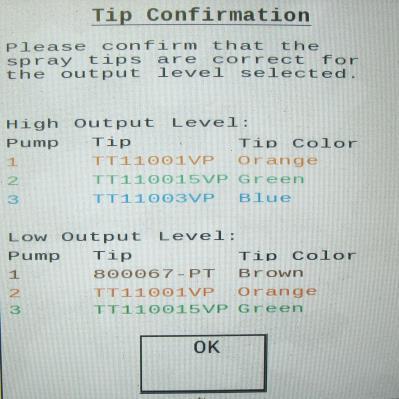
20 Setting Up Application Rate and Bale Parameters for Initial Use In the SETUP MODE you will set your initial application rate and baling rate. Application Rate Setup After pushing the SETUP MODE key in the MAIN MENU screen, the top left screen will show on the display: On this screen the operator will press the APPLICATION SETUP (1) key. 2. Press any of the underlined numbers to the right of %MC (2) to adjust their figures. Remember level 1 must be lower than level 2 and level 2 must be lower than level 3. Harvest Tec products recommend set points of 16, 19 and 22% MC levels. These are preset from the factory. 3. To change Rate (3) of chemical application press any of the underlined numbers to the right of RATE. Remember level 1 must be lower than level 2 and level 2 must be lower than level 3. Harvest Tec products recommend rates of 4, 6, and 10 lbs/ton (2,3,5 L/MT). These rates are preset from the factory. Press Back (7) to return to previous screen. IT IS THE OPERATORS RESPONSIBILITY TO FOLLOW RECOMMENDATIONS OF PRESERVATIVE. ONLY THE OPERATOR CAN APPLY PROPER RATE. 4. To set the Alarm (4) press on the underlined area and set the level at which you want the alarm to activate. To turn the Alarm OFF, set level above Press the underlined area next to Tip Output (5) to cycle between the High and Low sets of tips. The High tips will cover outputs of lbs/hr at approximately tons/hr. The Low tips will cover outputs of lbs/hr at approximately tons/hr. Use the correct tip set for the field conditions. 6. The Pump Module (6) needs to be turned ON for the pumps and flow meter to function. 7. Next press the Back (7) key found on the bottom left hand side of the screen to return to SETUP MODE screen or press the MAIN MENU (8) key to return to the opening screen. Tip Outputs High Output Tips for Rates Requiring lbs/hr. (Approximately tons/hr) Blue tips (Part #: 004-TT11003VP) Green tips (Part #: 004-TT110015VP) Orange tips (Part #: 004-TT11001VP) 7 --Blue Hose --Green Hose --Clear Hose 6 8 Low Output Tips for Rates Requiring lbs/hr. (Approximately tons/hr) Green tips (Part #: 004-TT110015VP) --Blue Hose Orange tips (Part #: 004-TT11001VP) --Green Hose Olive Green tips (Part #: PT) --Clear Hose 20
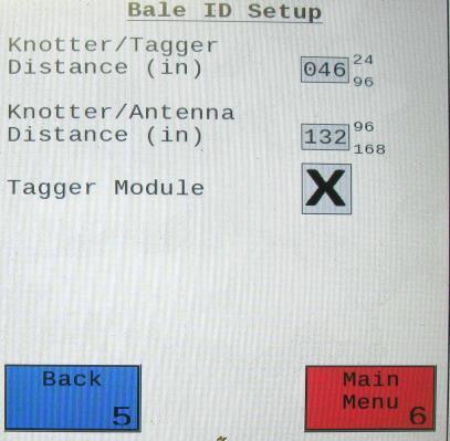
21 Baling Rate Setup After pushing the SETUP MODE key in the MAIN MENU screen, the top screen should appear: On this screen the operator will Select the BALING RATE SETUP (1) key. 2. Select the number to the right of AVG Bale Weight (2): to adjust the weight of your bales. The key pad shown will display. Select any number combination in this screen within the min/max limits. The information will remain until it is changed again. 3. Select the number to the right of AVG Bale Length (3): to adjust the length of your bales. Select any number combination in this screen within the min/max limits. The information will remain until it is changed again. 4. Select the number to the right of Time Per Bale (4): to adjust the time it takes to make a bale. Select any number combination in this screen within the min/max limits. The information will remain until it is changed again. 5. Select the number to the right of Knotter/Star (5) to adjust the distance between the knotter and star wheel. To determine the distance, measure between the center of the starwheel and the center of the knotter. This is important so the job record correlates to the bale being made. 6. When the AUTO Bale Rate (6) sensors are ON the applicator will calculate your tons per hour automatically. When the AUTO Bale Rate sensors are OFF a constant tons per hour (your inputed bale weight and time) will be used. Operating the unit with the AUTO Bale Rate sensors OFF will cause total tons per hour in Job Records to be left blank. Select the underlined word to toggle between ON or OFF. First Time and Annual Setup is checking with AUTO Bale Rate sensors OFF. 7. Selecting the Sensors (7) will allow you to use the Baler Sensor if your baler is equiped with them from the factory. The sensors will come OFF as a default. If you choose to use the baler sensors be sure your baler is equipped with that option. For example, if you do not have an electronic bale length kit, turn the sensor to OFF. The baler End of Row sensors are triggered once the PTO speed goes below 600RPM. The End of Bale sensor is triggered by the tie cycle alarm. The Bale Scale sensor is for the baler equiped with a Chute Scale. Note: Baling on rough terrain or hills can cause the scale to give an inaccurate reading. Turn Bale Scale option OFF in the Bale Rate Screen and use AVG Bale Weight (2) reading as weight of bale. 8. Next select the Back (8) key found on the bottom left hand of the screen to return to the SETUP MODE screen, or select the MAIN MENU (9) key on the bottom right hand of the screen to return to the opening screen. 9. Select the OPTIONS (10) key to adjust the 11 system between metric and standard units. The Crop Eyes (11) can also be turned ON or OFF in the OPTIONS screen. Select the ON/OFF next to Crop Eyes to change this setting. Note: If you change languages you may need to reset the system from the MAIN MENU screen. 21

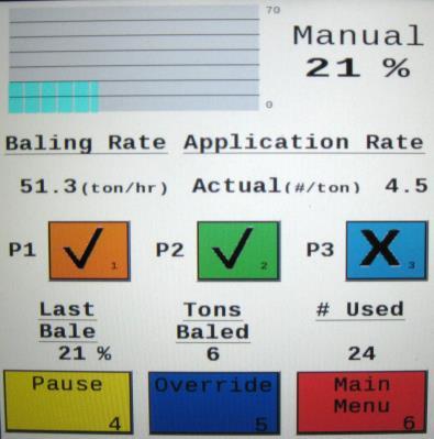
22 Operating Instructions Automatic Mode will automatically apply product based on both hay moisture content sensed by the star wheels and the operator s preset parameters. See Setting Up System for Initial Use to change any of these settings. Manual Mode will apply preservative to the hay at a fixed rate regardless of the moisture content or baling rate. Automatic Mode After pushing the AUTOMATIC MODE key in the MAIN MENU screen, the following screen should appear: Push the Pause key (1) to stop application while in operation. 2. Push the Override key (2) to turn on all three pumps at the same time for full output of the system. Use this mode when going through a short area of wet crop. 3. The Moisture Content (3) is shown in the upper right hand corner. 4. Baling Rate and Application Rate (4) are shown in the middle. The operator sets the target application rate in the SETUP MODE. The ACTUAL rate should be within +/- one pound when running. The Baling Rate is also calculated in the SETUP MODE. 5. The Graph (5) shows the moisture trend from the past 90 seconds in 3 second intervals. 6. The totals on the bottom of the screen show the total Tons Baled and # Used (pounds of product used) (6) for the current job. These numbers will reset to zero when a new Job Record is started. If operating with Bale Rate Sensors OFF total Tons Baled will be zero. 7. Last Bale (7) shows the average moisture content for the last bale. 8. Any Status Alerts for the system will appear in the middle of the screen. See the Status Alerts section for information. 9. Press the MAIN MENU (8) key to return to the opening screen. 2
23 Manual Mode After pushing the MANUAL MODE key in the MAIN MENU screen, the following screen should appear: Push the Pause key (1) to stop application while in operation. 2. Push the Override key (2) to turn on all three pumps at the same time for full output of the system. Use this mode when going through a short area of wet crop. 3. In MANUAL MODE you can turn the pumps ON or OFF by pressing the underlined area next to the pump numbers. In MANUAL MODE (regardless of moisture, tons per hour or bale weight) the outputs of the pumps are fixed rates as follows: Low output tips: Pump 1 = 60 LBS/HR Pump 2 = 100 LBS/HR Pump 3 = 150 LBS/HR High output tips: Pump 1 = 100 LBS/HR Pump 2 = 150 LBS/HR Pump 3 = 300 LBS/HR 4. The Moisture Content (3) is shown in the upper right hand corner. 5. Baling rate and Application rate (4) are shown in the middle. The output of a pump can be checked by dividing the preset output (shown in step 3) by the baling rate. For example, if you have the high output tips in and are running pump three by itself, your output is 300 lbs/hr. Given the Baling Rate (4) shown on the above screen (79.5 tons/hr), the application rate should be about 3.77 lbs/ton (300lbs/hr divided by 79.5 tons/hr). 6. The Graph (5) shows the moisture trend from the last 90 seconds of baling (one reading every 3 seconds). 7. The Totals at the bottom of the screen show the total Tons Baled and # Used (pounds of product used) (6) for the current job. These numbers will reset to zero when a new Job Record is started. If operating with AUTO Bale Rate sensors OFF total tons baled will be zero. 8. The Baling Rate (4) is set in the SETUP MODE menu. 9. Last Bale (7) shows the average moisture content for the last bale. 10. Press the MAIN MENU (8) key to return to the opening screen. 23
 key. In the next screen enter the date (month, day, year format) followed by the time.")
 time. 2. Select the Software Versions key to check all software versions of modules attached to the Dual Channel Processor (DCP).")
24 Diagnostics After pressing the DIAGNOSTICS key in the MAIN MENU screen, the screen on the left should appear: 1. To set date and time select the Set Date/Time (1) key. In the next screen enter the date (month, day, year format) followed by the time. When done select the OK key (2). NOTE: The clock uses military (or 24 hour) time. 2. Select the Software Versions key to check all software versions of modules attached to the Dual Channel Processor (DCP). The information will appear in the screen shown below right Press the MAIN MENU (4) key to return to the opening screen. 24
 will save all the previous bale records and open the Field Name (2) screen. 2. Use the key pad in the Field Name screen to enter up to an eight character field name.")
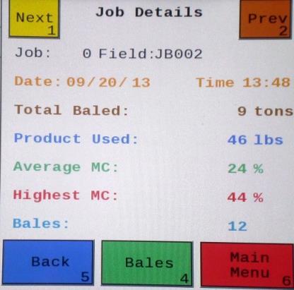
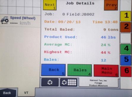
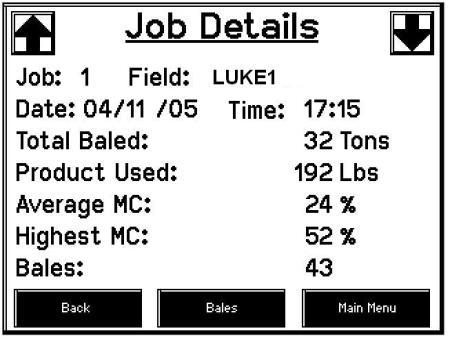
 will open the Job Details screen. Use the Next and Prev (4) icons to view the different jobs. Job: 0 will always be your current and open job record.")
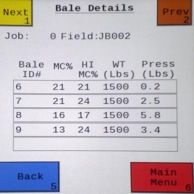
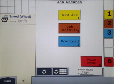
25 Job Records After pushing the JOB RECORDS key in the MAIN MENU screen, the upper left screen below should appear: Selecting New Job (1) will save all the previous bale records and open the Field Name (2) screen. 2. Use the key pad in the Field Name screen to enter up to an eight character field name. Use the asterisk key to move on to the next letter or number if they are identical. Use the pound sign as a space between the characters. When you have completed the field name press enter. 3. Pressing Job Details (3) will open the Job Details screen. Use the Next and Prev (4) icons to view the different jobs. Job: 0 will always be your current and open job record. Press Back (5) to go to the Job Records screen or Main Menu (6) for the main screen. 4. Selecting Bales (7) at the center bottom of the screen will open a Bale Details screen (8). This screen lets you look at the individual bale records for the first five bales made. Use the Next and Prev icons to scroll through five bales at a time. Select Back to go to the Job Details screen or Main Menu for the main screen. Continued on the next page 25


26 Job Records (continued) Selecting the Download (9) key (in the job records screen) will open the Download Job Records screen, shown above. This screen lets you select jobs to download onto a USB drive. To download insert a USB drive into the port on the Dual Channel Processor. Select the job(s) you would like to download using the Next and Prev icons to highlight the job(s). Once the desired jobs are selected press the Download (10) key. Press the Download key again to confirm. When the USB drive light goes off all the jobs selected will be saved. The jobs can then be opened on any computer with Excel or Notepad. To delete jobs highlight, select them and press Delete (11) followed by pressing Delete again for confirmation. Press Back to go to the Job Records screen or Main Menu for the main screen. 2. Pressing the Select (12) key will select or unselect the highlighted job. 3. Pressing the Select All (13) key will select all jobs, except for the current job (0). To unselect press the Back key. 4. The job record in Excel will show as on the left above. The Bale ID column will need to be adjusted for proper viewing. 5. The job record in Notepad will show as on the right above. You will need to scroll right to see all the information. 26


27 Maintenance If you are unsure how to perform any of the maintenance steps have your local authorized dealer perform the tasks. Maintenance Schedule Daily 10 hrs 400 hrs Weekly Monthly Season Diagnostics X X Filter bowl cleaning X X Tips & tip screen cleaning X X Tank lid cleaning X X Dielectric grease connections X X Rebuild pumps X Battery connections X X Check valves X Visually inspect hoses X X Diagnostics: Follow the instructions in this manual to run the Diagnostics mode. Filter bowl cleaning: The filter bowl is located in front of the applicators tank and is connected to the ball valve. Before cleaning the filter bowl all personal protective equipment must be worn (Face shield or goggles, chemically resistant apron, boots, and gloves). Verify that the ball valve located next to the pump is turned off. Locate the filter bowl on the side of the pump manifold (A). Unscrew the bottom section of the filter bowl and remove the strainer (B). Clean off any debris and soak in warm water with a mild soap if necessary. Once the screen is clean reinstall by following the directions in reverse. A B 27
.")
. Hold the nozzle body from turning while removing the nozzle caps with a 11/16 inch wrench. Remove the tip, and screen.")
28 Tips and Tip Screen Cleaning: The spray shield assembly that holds the tips and tip screens is located above the pickup head. Before cleaning the tips and screens all personal protective equipment must be worn (Face shield or goggles, chemically resistant apron, boots, and gloves). Verify that the ball valve located next to the pump is turned off. Disconnect spray shield from hangers by removing the lynch pins (A). Disconnect check valve nuts and remove hoses from shield (B). Remove shield from baler. Remove all six nozzle caps with a 7/8 inch wrench (C). Hold the nozzle body from turning while removing the nozzle caps with a 11/16 inch wrench. Remove the tip, and screen. Clean off any debris and soak in warm water with a mild soap if necessary. Once the tips and screens are cleaned reinstall by following the directions in reverse. B A C 28

29 Tank Lid Cleaning: Before cleaning the tank lid all personal protective equipment must be worn (Face shield or goggles, chemically resistant apron, boots, and gloves). The tank lid is located on the top of the tank. Use the supplied handle on the tank to secure your person and use the other hand to remove any debris from the top of the tank. Unscrew the tank lid and bring down ground level. Use compressed air clean out the tank breather (D). Once the breather is cleaned reinstall the cover. D Dielectric Grease Connections: Disconnect all harnesses on the applicator, clean the connections, and repack with dielectric grease. Rebuild Pumps: If Diagnostic or Manual mode show that the pumps are running lower than normal, a pump rebuild may be necessary. To do this rebuild the pump must be removed from the pump manifold. Pump rebuild is part no A service pack that includes pump rebuilds and check valves is available from your local dealer. Verify that the ball valve is turned off. Before working around the pumps all personal protective equipment must be worn (Face shield or goggles, chemically resistant apron, boots, and gloves). Remove pump from manifold. Follow rebuild instructions supplied with pump rebuild kit. Reinstall after rebuild is complete. Battery Connections: Follow the batteries safety warnings and clean the battery connections. If the connections cannot be cleaned, replace harness. Check Valves: Before servicing the check valves all personal protective equipment must be worn (Face shield or goggles, chemically resistant apron, boots, and gloves). Verify the ball valve is turned off before service the check valves. Replace the intake check valves by the pumps ( F) and the discharge check valves by the tip ( VB). Miscellaneous Maintenance: 1. Depending on the product being used, the system may need to be flushed with water at a regular interval (consult with manufacturer of the chemical.) If Harvest Tec product is being used, flushing is not necessary. 2. Although the pump can run dry, extended operation of a dry pump will increase wear. Watch the preservative level in the tank. 3. If you are using bacterial inoculants, flush your system daily after every use. 29
30 Winter Storage 1. Thoroughly flush the system with water. 2. Remove the filter bowl and run dry until the water has cleared out of the intake side. 3. Remove the red plug from the bottom of the pump, drain, and run the pump for 30 seconds or until dry. 4. Drain all lines on the outlet side. 5. Never use oils or alcohol based anti-freeze in the system. 6. For spring start-up, if the pump is frozen, turn off the power immediately to avoid burning the motor out or blowing a fuse. The pump head can be disassembled and freed or rebuilt in most cases. Check the fuses after the pump has been freed. 7. Disconnect power from the Precision Information Processor. 8. Remove display from tractor and store in a warm, dry place. Status Alerts Two Status Alerts will appear on the Auto and Manual mode screens when the Job Records are approaching, or full of records. Status Alert Bale Records: Less than 1K remaining. The system is now approaching the maximum amount of records that can be saved. When this code appears, download and delete jobs in the Job Records menu. Follow the instructions in Job Records to accomplish this. Status Alert Bale Records failed Memory Full. The system will no longer accept any new data until jobs in the Job Records menu are downloaded and deleted. Follow the instructions in Job Records to accomplish this. 30
31 Wiring Diagram A. The Baler Power/Communication Harness ( LS2) will attach to the open port of the Tractor Harness ( TME) and run back to the Dual Channel Processor (DCP LS). B. Connect the large plug of the Baler Power/Communication Harness ( LS2E) to the bottom (shorter side) of the DCP. Attach the Baler Interface Harness ( VAJ) in between the short whip cable hardwired to the DCP and the main Power/Communication Harness. Make sure Active Terminator removed from the baler processor is attached to the Baler Interface Harness ( VAJ). C. Install the Terminating Connector ( Z) to the Modular Port on the Pump Controller ( ). D. Attach moisture and bale rate harness ( HE) to the DCP ( LS). E. Attach the Pump Control Harness ( FME) between the Pump Controller ( ) and the DCP ( LS). F. Connect Keyed Power Extension harness ( K) to a keyed power source. G. Connect Bluetooth Receiver ( A) to Communication Harness ( TM). H. Note: the Optional Port and the Data Transfer Port are not used in this application. Star Wheel Assembly (2X) Proximity Sensor (2X) S Moisture/Bale Rate Harness HE Data Transfer Dual Channel Processor (DCP) LS End of Bale Sensor Flow Meter A Pump Controller Optional Port Pump Harness Z Bluetooth Receiver A Terminating Connector Z Pump Controller Harness FME or F3ME Active Terminator from Baler Harness Orange Wire to Keyed Power K Baler Connection Baler Interface Harness VAJ Power/Comm Harness on Bale LS2E Power/Comm Harness on Tractor TME 31


32 Pin Outs Power/Comm Harness TME at Hitch Pin 1 Red +12V Power to TSD Pin 2 Red +12V Power to DCP Pin 3 Orange Keyed Power Pin 4 Gray Shield Pin 5 Green HT Can Low Pin 6 Yellow HT Can Hi Pin 7 Orange Can1 Hi Pin 8 Black Ground from TSD Pin 9 Black Ground from DCP Pin 10 Blue Can1 Low Power/Comm Harness LS2 at Hitch Pin 1 Red +12V Power to TSD Pin 2 Red +12V Power to DCP Pin 3 Orange Keyed Power Pin 4 Gray Shield Pin 5 Green HT Can Low Pin 6 Yellow HT Can Hi Pin 7 Orange Can1 Hi Pin 8 Black Ground from TSD Pin 9 Black Ground from DCP Pin 10 Blue Can1 Low Display Plug or Bluetooth Receiver on Harness TM Pin 1 Red +12V Power from DCP Pin 2 Black Ground from TSD Pin 3 Yellow HT Can Low Pin 4 Gray Shield Pin 5 Green HT Can Hi Pin 6 Orange Can1 Hi Pin 7 Blue Can1 Low ISOBUS Plug Baler Side Pin 1 N/A Pin 2 N/A Pin OHM with Pin 5 Pin 4 N/A Pin OHM with Pin 3 Pin 6 Orange Can1 Hi Pin 7 Blue Can1 Low ISOBUS Plug Tractor Side Pin 1 N/A Pin 2 N/A Pin 3 +12V Keyed Tractor Power Pin 4 N/A Pin 5 N/A Pin 6 N/A Pin 7 N/A Pin 8 Orange Can1 Hi Pin 9 Blue Can1 Low 32


33 Pin Outs (continued) Main Power Connector on DCP Pin 1 Red +12V Power from tractor Pin 2 Black Ground from tractor Pin 3 Orange Keyed power Star Wheel and Bale Rate Sensor connector on DCP Pin 1 Blue +12V Power Pin 2 Orange Ground Pin 3 Black Signal for sensor 1 Pin 4 White Signal for sensor 2 Pin 5 N/A Pin 6 N/A Pin 7 N/A Pin 8 Violet Star wheel input 1 Pin 9 Brown Star wheel input 2 End of Bale sensor on DCP Pin 1 Brown Sensor Power Pin 2 Blue Sensor Ground Pin 3 N/A Pin 4 Black Signal from Sensor Pump Communication Plug on DCP Pin 1 Red +12V Can Pin 2 Red +12V Power Pin 3 Gray Shield Pin 4 Green Comm Channel OH Pin 5 Yellow Comm Channel OL Pin 6 Blue Comm Channel IH Pin 7 Orange Comm Channel IL Pin 8 Black Can Ground Pin 9 Black Power Ground Pin 10 N/A Pump Connection Colors Pin 1 Black with Orange Stripe Pin 2 Black with Green Stripe Pin 3 Black with Yellow Stripe Pin 4 N/A Pin 5 Orange with Black Stripe Pin 6 Green with Black Stripe Pin 7 Yellow with Black Stripe Pump 1 Ground Pump 2 Ground Pump 3 Ground Pump 1 Positive Pump 2 Positive Pump 3 Positive

34 Pin Outs (continued) Flow Meter Connection on Pump Controller Pin 1 White 5 12V (+) Supply Pin 2 Green Ground Pin 3 Brown Signal Pin 4 Black Shield Connector for Crop Eyes on DCP Pin 1 Red +12V Power Pin 2 Black Ground Pin 3 White Signal Pin 4 N/A VAJ Harness to Baler Plug Pin A N/A Pin B Red TBC Power Pin C N/A Pin D Gray TBC Ground Pin E Orange Can1 Hi Pin F Blue Can1 Low A D 34
35 Common Questions 1. How do I turn the system on/off? Turn the key in the tractor to the ON/OFF position. 2. How to get in the LBS/TON, MC%, and TONS/HR menus? In the Main Menu press the Setup Mode option. From this screen you can change your application rates and how much product is applied. See the section on Setting Up For Initial Use for a detailed explanation of this process. 3. The unit is stuck in the MC% screen. In the MC% screen, level 1 must be less than level 2, and level 2 must be less than level 3. For example, if level 1 is set at 16, level 2 must be set at 17 or higher, and level 3 must be set higher than level How does Override work? Override turns on all three pumps at full output. The pumps will remain at full output until the operator turns these pumps off by pressing the Override key again. 5. The flow meter reading is more or less than the programmed level set in the box. Some variation in flow meter readings compared to the programmed set point is normal due to factory tolerances on the pump motors as well as varying tractor voltages inputted to the control box. The flow meter reading is an accurate measure of how much product is actually being applied. The set points then will need to be adjusted if you want to attain a different flow meter reading. 6. Why don t all the pumps turn on even at higher application rates? The selections of what pumps turn on when are automatically controlled by the control box s flow rate look up chart. Thus, not all the pumps turn on at once and the combination of what pumps turn on when is automatically controlled by the software. If you want to make sure all three pumps are working, go to the Diagnostics screen and run pump outputs. 7. The moisture content displays LO or HI all the time. When the moisture content display does not change frequently while baling, there is likely a faulty star wheel connection. One of the first places to check is inside the white star wheel block. Check to see if the electronic swivel is in the star wheel shaft and check to see that the star wheel shaft is not working out of the block. Also, check all star wheel wires and connectors to see if there is a continuity or grounding problem. 8. Should the battery connections be removed before jump starting or charging a battery? Yes. Anytime the tractor will have voltage going up rapidly the connections should be removed. 9. How can I turn the optional hay indicators Crop Eyes On/Off from the cab? From the Setup Mode screen press Options. Press the On/Off underlined area next to Crop Eyes. 10. Bale scale does not give a consistent reading. Baling on rough terrain or hills can cause the scale to give an inaccurate reading. Turn Bale Scale option OFF in the Bale Rate Screen and use AVG Bale Weight reading as weight of bale. 35
36 Troubleshooting Problem Possible cause Solution Pump will not run. 1. No voltage to DCP or Pump controller. 1. Check for short, low voltage, and replace fuse(s) if necessary. 2. Pump locked up. 2. Clean or rebuild pump if motor is OK. 3. Damaged wire. 3. Repair damaged wire. 4. Fuse blown on Pump controller. 4. Replace fuse and check pump for short in wire or locked motor. Pump runs but will not prime. 1. Air leak in intake. 1. Tighten fittings on intake side. 2. Clogged intake. 2. Clean. 3. Restricted outlet. 3. Check and clean tips. 4. Check valve on the outlet is 4. Clean or repair check valve. stuck closed. 5. Dirt inside pump. 5. Replace pump check valve. Pump does not develop enough output. 1. Air leaks or clogs on inlet side. 1. Tighten or clean filter bowl assembly. 2. Pump worn or dirty. 2. Rebuild pump. Moisture reading errors (high or low) 1. Wire disconnected or bad connection between star wheels 1. Reconnect wire. Moisture readings erratic. Flow meter readings do not match up with product usage. Product is less than actual product used. Product shown is more than actual product used. and DCP 2. Low power supply to DCP 2. Check voltage at box. (Min of 12 volts required.) See Diagnostics section of manual. 3. Wet hay over 75% moisture 4. Ground contact with one or both star wheels and baler mounted processor. 5. Short in wire between star wheels and DCP. 6. Check hay with hand tester to verify. 1. Test bales with hand tester to verify that cab monitor has more variation than hand tester. 2. Check all wiring connections for corrosion or poor contact. 3. Check power supply at tractor. Voltage should be constant between 12 and 14 volts Reconnect. 5. Replace wire. 6. Contact Harvest Tec if conditions persist. 2. Apply dielectric grease to all connections. 3. Install voltage surge protection on tractors alternator. 1. Voltage supplied to meter is less 1. Check for a min of 6 volts than 6 volts. supplied at Pump controller. 2. Wiring short in signal to baler 2. Inspect wire and replace if mounted processor. necessary. 3. Clog in meter. 3. Back flush with water. DO NOT USE AIR. 4. Using product other than 4. Catch and weigh product to Harvest Tec check outputs. 1. High voltage supplied to the 1. Check voltage at Pump meter. controller. Max of 18 volts. 2. Light interference with meter. 2. Reflection into meter can cause a high reading. Move meter or protect from sunlight. 3. Air leak in intake. 3. Look for air bubbles in line. Replace line or other defective area that is allowing air into the system. 4. Using product other than 4. Catch and weigh product to Harvest Tec check outputs.
37 System leaks product after shut down. 1. Dirty or defective check valves. 1. Clean or Replace. Terminal reads under or over power. 1. Verify with multi-meter actual voltage. Voltage range should be between volts. 1. Clean connections and make sure applicator is hooked to battery. See Diagnostics section System does not pause at the end of a row. Bale rate displays zero. Display is locked up/froze. Display powers up when key is turned and will not go to the Main Menu screen. Display is locked up/froze and pumps continue to run. Display says PAC error 1. Short in cable. 2. Damaged sensor. 3. Bad alignment of sensors 1. Bale rate sensors are reversed. 2. Short in cable. 3. Damaged sensor. 1. CAN communication not responding. 2. Broke connection between the display and DCP or Pump control and DCP. 1. CAN communication not responding. 2. Broke connection between the display and DCP or Pump control and DCP. 1. CAN communication not responding. 2. Broke connection between the display and DCP or Pump control and DCP. 1. The DCP and Pump controller are not communicating. 2. Broke connection between the display and DCP or Pump control and DCP. of manual. 1. Replace cable. 2. Replace sensor 3. Check 474 manual for alignment instructions 1. Switch the sensors next to the star wheel. 2. Replace cable. 3. Replace sensor. 1. Check connections at DCP and Pump controller including the terminating resistors. 2. Check, clean, and tighten connections. 3. Power unit down and restart after steps 1 & 2 are complete. 1. Check connections at DCP and Pump controller including the terminating resistors. 2. Check, clean, and tighten connections. 3. Power unit down and restart after steps 1 & 2 are complete. 1. Check connections at DCP and Pump controller including the terminating resistors. 2. Check, clean, and tighten connections. 3. Power unit down and restart after steps 1 & 2 are complete. 1. Check all connections at DCP and Pump controller including terminating resistors. 2. Check, clean, and tighten connections. 37


38 Parts Breakdown Tank, Saddle and Legs 110 Gallon Tank Lid Part#: E or L Tank-110 gallon Part#: Hand Rail Part#: HR Tank Straps Part#: B Not Pictured: Elbow Part#:003-EL3412 Tank Saddle Part#: A Tank Fitting Part#: John Deere L330 / L340 Part#: J 38

39 Parts Breakdown for Pump Manifold c 4 12a 9 12b Ref# Description Part# Qty Ref# Description Part# Qty 1 Pump plate D 1 12a Filter bowl only F 1 2 Mounting Bracket C 1 12b Filter bowl gasket D 1 3 Pump H 3 12c Filter bowl screen A 1 4 Street elbow fitting 003-SE Nipple fitting 003-M Nipple fitting 003-M Ball valve Check valve F 3 15 Street elbow fitting 003-SE Elbow fitting 003-EL Hose clamp Tee fitting 003-T3812HB 2 17 Hose clamp (Flow Meter) Flow meter assembly A 1 18 Pump Cable Z 1 10 Straight fitting 003-A NP Elbow 003-EL Jaco fitting 003-JEL NP Pump rebuild kit (1/pump) Filter bowl assembly NP Not Pictured 39
 w/006-4642k 1 9 Plug fitting 003-F38 2 3 Snap ring (per side) w/006-4642k 2 10 Block Cover")

 002-9016 35ft 6 Valve Holder 001-6702H 1 002-9016B 35ft 7 Female")
 002-9002 10ft 11 Hose Clamps 003-9004 2 4 Straight Fitting 003-A3434 1 5 Ball")
40 Parts Breakdown for Star Wheel Moisture Sensors Ref Description Part# Qty Ref Description Part# Qty 1 Washer (per side) K 2 8 Star wheel block A 2 2 Dust seal (per side) w/ k 1 9 Plug fitting 003-F Snap ring (per side) w/ k 2 10 Block Cover B 2 4 Swivel A Star wheel assembly Star wheel E 2 NP Twine guard right (prox) Insert w/ Ref # 5 2 NP Twine guard left Wiring grommet A Bale Rate Sensors Ref Description Part# Qty 12 Bale rate sensor S 2 13 Moisture and bale rate harness H 1 13 Complete Assembly Parts Breakdown for Hose and Drain Fill Line Ref Description Part# Qty Ref Description Part# Qty 1 Triple weld hose (pumps to tips) ft 6 Valve Holder H B 35ft 7 Female Coupler A G 35ft 8 Male Coupler G 1 Three hose assembly LS 1 9 Elbow 003-EL /2 Hose (tank to filter) ft 10 Jiffy Clip /4 Hose (tank to drain/fill) ft 11 Hose Clamps Straight Fitting 003-A Ball valve

 001-4648J 1 NP Baler Integration Harness 006-6650VAJ 1 NP Optional ISOBUS Adapter Plug")
41 Parts Breakdown for 696J Series Control and Harnesses Dual Channel Processor (DCP) Ref Description Part Number Qty 1 Pump Controller End of Bale Sensor DCP Shield Cover X 1 4 DCP Main Control LS 600 AUTO LS 1 5 Terminating Connector w Green Cap Z 1 6 DCP Baler Harness 30 Ft LS2 1 7 Modular Power/Comm 10 Ft Harness FM 1 8 DCP Tractor Harness TM 1 9 Key Switch Wire K 1 10 Dust Plugs PLUGS 1 11 Bluetooth Receiver A 1 NP EOB Bracket (JD L330, L340) J 1 NP Baler Integration Harness VAJ 1 NP Optional ISOBUS Adapter Plug A
 004-TT11001VP 2 3 Elbow 003-SE14F 3 Tip (green) 004-TT110015VP 2 4 Straight fitting 003-A1414 6 Tip (blue) 004-TT11003VP 2 5 Hose 002-9016 6ft 6 Hose clamp 003-9002 9 7 Tee 003-TT14SQ 3")
42 4525JB Installation Kit Ref Description Part # Qty Description Part # Qty 1 Spray shield ES 1 Tip (olive green) PT 2 2 Shield holder EJ 1 Tip (orange) 004-TT11001VP 2 3 Elbow 003-SE14F 3 Tip (green) 004-TT110015VP 2 4 Straight fitting 003-A Tip (blue) 004-TT11003VP 2 5 Hose ft 6 Hose clamp Tee 003-TT14SQ 3 8 Check valve VB 3 9 Straight fitting 003-A1414VB 3 10 Lynch pin Nozzle body Nozzle cap Tip strainer Pump Plate Holder JX 2 (Not Included w/ Install Kit) 42
43 Optional ipad Mini Mounting Kit ( MK) Ref Description Part # Qty 1 Suction cup mount SCM 1 2 Ram mount H 1 3 ipad Mini spring load cradle (Mini 1,2,3) SLC gauge power wire P 1 5 Female spade connector Hardware 2 6 Eye loop connector Hardware 2 7 ipad Mini Charger 12V P 1 8 ipad Mini 2 case C2 1 NP 4 amp fuse Hardware 1 Mounting Kit Assembly MK (Includes All Parts) Installation Instructions 1. Identify 12V power source for wires to connect. a. Eye loops included if wiring directly to the battery is desired. b. Test for key power source if preferred to have power to the USB shut off with the key. 2. Once power source is identified, cut wires to desired length. 3. Crimp the two supplied quick connectors onto each the white and black wire. 4. Remove the round locking plastic nut from USB plug before connecting the wires. Black (+) White (-). 5. The wires will then be hooked to the designated terminals on the bottom of the USB plug 6. Drill a 1 1/8 hole in the preferred mounting location. Be sure to clean any sharp edges after drilling. 7. Feed the wires through the mounting hole. 8. If using the round plastic nut to secure plug in place, slide the nut back over the wiring before connecting the wires to powered source. 9. Connect the wires to the identified power source if easier to do so before tightening the plug into place. 10. Tighten plug using either the round plastic nut or mounting plate and two screws, both options supplied. 11. Once connected, hook a USB charging cord into the plug and connect a mobile device/tablet to ensure the plug is operating as you wish (key power working properly if necessary). NOTE: This plug is not designed to charge two ipads. System damage could occur if this is attempted. System will charge a mobile phone and ipad simultaneously without problem. 43
 001-2012SLC 1 9 ipad Mini 2 006-2670IP 1 4 16 gauge power wire 006-4723P 1 NP 4 amp fuse Hardware 1 5 Female")
44 Optional ipad Display Kit ( DK) Ref Description Part # Qty Ref Description Part # Qty 1 Suction cup mount SCM 1 7 ipad Mini Charger 12V P 1 2 Ram mount H 1 8 ipad Mini 2 case C2 1 3 ipad Mini spring load cradle (Mini 1,2,3) SLC 1 9 ipad Mini IP gauge power wire P 1 NP 4 amp fuse Hardware 1 5 Female spade connector Hardware 2 6 Eye loop connector Hardware 2 Mounting Kit Assembly DK (Includes All Parts) Installation Instructions 12. Identify 12V power source for wires to connect. a. Eye loops included if wiring directly to the battery is desired. b. Test for key power source if preferred to have power to the USB shut off with the key. 13. Once power source is identified, cut wires to desired length. 14. Crimp the two supplied quick connectors onto the white and black wire. 15. Remove the round locking plastic nut from USB plug before connecting the wires. Black (+) White (-). 16. The wires will then be hooked to the designated terminals on the bottom of the USB plug 17. Drill a 1 1/8 hole in the preferred mounting location. Be sure to clean any sharp edges after drilling. 18. Feed the wires through the mounting hole. 19. If using the round plastic nut to secure plug in place, slide the nut back over the wiring before connecting the wires to powered source. 20. Connect the wires to the identified power source if easier to do so before tightening the plug into place. 21. Tighten plug using either the round plastic nut or mounting plate and two screws, both options supplied. 22. Once connected, hook a USB charging cord into the plug and connect a mobile device/tablet to ensure the plug is operating as you wish (key power working properly if necessary). NOTE: This plug is not designed to charge two ipads. System damage could occur if this is attempted. System will charge a mobile phone and ipad simultaneously without problem. 44
Operation Manual A. Touch Screen Display (TSD) for 600 Series A-OPR 11/13
 for 600 Series A-OPR 11/13") Operation Manual 030-5670A Touch Screen Display (TSD) for 600 Series 030-5670A-OPR 11/13 1 (intentionally blank) 2 Harvest Tec Touch Screen Display Table of Contents 5670A PAGE Introduction 4 Safety 4
Operation Manual 030-5670A Touch Screen Display (TSD) for 600 Series 030-5670A-OPR 11/13 1 (intentionally blank) 2 Harvest Tec Touch Screen Display Table of Contents 5670A PAGE Introduction 4 Safety 4
Operation Manual. Model 696M-M. 110 Gallon Preservative Applicator 696M-16-M-OPR-BLE 9/16
 Operation Manual Model 696M-M 110 Gallon Preservative Applicator 696M-16-M-OPR-BLE 9/16 DECLARATION OF INCORPORATION MANUFACTURER: Harvest Tec Inc. 2821 Harvey St. P.O. Box 63 Hudson, WI 54016, U.S.A.
Operation Manual. Model 445, 451 & & 55 gallon Automatic Preservative Applicator. # OPR Revised 3/16
 Operation Manual Model 445, 451 & 450 25 & 55 gallon Automatic Preservative Applicator #010-0445-450-451-OPR Revised 3/16 Introduction Congratulations on purchasing a Harvest Tec Model 445, 450 & 451 applicator.
Model 446, 447 & & 55 gallon Preservative Applicators
 Operation Manual Model 446, 447 & 449 25 & 55 gallon Preservative Applicators #00-0446-447-449-OPR Revised /3 Introduction Congratulations on purchasing a Harvest Tec Model 446 or 447 or 449 applicator.
Small Square Baler Models
 Operation Manual Small Square Baler Models 25 & 55 gallon Preservative Applicators 444T-445T-450T-451T-OPR 4/16 (intentionally blank) 2 Small Square Baler Models Operation Table of Contents Page Introduction
Installation Manual. Model 600. Moisture Sensor Kit for Large Square Balers INST-Imp&Metric 5/18
 Installation Manual Model 600 Moisture Sensor Kit for Large Square Balers 600-17-INST-Imp&Metric 5/18 DECLARATION OF INCORPORATION MANUFACTURER: Harvest Tec Inc. 2821 Harvey St. P.O. Box 63 Hudson, WI
Operation Manual. 300 Series Round Baler Models. 25 & 55 gallon Preservative Applicators C-347U OPR-Imp & Metric 4/19
 Operation Manual 300 Series Round Baler Models 25 & 55 gallon Preservative Applicators 337-34-347-347C-347U-349--OPR-Imp & Metric 4/9 DECLARATION OF INCORPORATION MANUFACTURER: Harvest Tec Inc. 22 Harvey
Installation Manual. Model 337-M. 25 Gallon Automatic Preservative Applicator INST-M 3/17
 Installation Manual Model 337-M 25 Gallon Automatic Preservative Applicator 337-16-INST-M 3/17 1 DECLARATION OF INCORPORATION MANUFACTURER: Harvest Tec Inc. 2821 Harvey St. P.O. Box 63 Hudson, WI 54016,
Installation Manual. Model 697BB. 115 Gallon Preservative Applicator For New Holland BigBaler and Case IH LB BB-16-INST (Imp&Metric) 11/18
 11/18") Installation Manual Model 697BB 115 Gallon Preservative Applicator For New Holland BigBaler and Case IH LB 4 697BB-16-INST (Imp&Metric) 11/18 DECLARATION OF INCORPORATION MANUFACTURER: Harvest Tec Inc.
Installation Manual Model 697BB 115 Gallon Preservative Applicator For New Holland BigBaler and Case IH LB 4 697BB-16-INST (Imp&Metric) 11/18 DECLARATION OF INCORPORATION MANUFACTURER: Harvest Tec Inc.
Operation Manual. Electronic XHI System. High Output Electronic Preservative Applicator Metric. Electronic XHI-17-OPR-M 4/17
 Operation Manual Electronic XHI System High Output Electronic Preservative Applicator Metric Electronic XHI-7-OPR-M 4/7 DECLARATION OF INCORPORATION MANUFACTURER: Harvest Tec Inc. 282 Harvey St. P.O. Box
Installation Manual. Model 347U-M. 25 Gallon Automatic Preservative Applicator 347U-16-INST-M 5/17
 Installation Manual Model 347U-M 25 Gallon Automatic Preservative Applicator 347U-16-INST-M 5/17 1 DECLARATION OF INCORPORATION MANUFACTURER: Harvest Tec Inc. 2821 Harvey St. P.O. Box 63 Hudson, WI 54016,
Operation Manual. 300 Series Small Square Baler Models. 25 & 55 gallon Preservative Applicators OPR 4/18
 Operation Manual 300 Series Small Square Baler Models 25 & 55 gallon Preservative Applicators 344-345-350-351-OPR 4/18 1 (intentionally blank) 2 Small Square Baler Models Operation Table of Contents Page
Model 440, 441, 442 & 448
 Operation Manual Model 440, 44, 44 & 448 & gallon Preservative Applicator 440-44-44-448-OPR /6 (intentionally blank) Harvest Tec 440, 44, 44 & 448 OPERATION Table of Contents Page Model Reference Introduction
Installation Manual. Model 300SS-M. Moisture Only Kit for Small Square Balers 300SS-16-INST-M 3/17 1
 Installation Manual Model 300SS-M Moisture Only Kit for Small Square Balers 300SS-16-INST-M 3/17 1 (intentionally blank) 2 300SS Installation Manual Table of Contents Page Introduction 4 System Requirements
Operation Manual. Model & 110 Gallon Preservative Applicator OPR 10/15
 Operation Manual Model 9 00 & 0 Gallon Preservative Applicator 9--OPR 0/ (intentionally blank) Harvest Tec Model 9 Operation Table of Contents Page Introduction Installation Kit Reference Chart - Safety
Installation Manual. Model 600. Moisture Sensor Kit for Large Square Balers 600-INST 4/16
 Installation Manual Model 600 Moisture Sensor Kit for Large Square Balers 600-INST 4/16 (intentionally blank) 2 Harvest Tec Model 600 Installation Table of Contents PAGE Introduction 4 System Requirements
Installation Manual. Model 664. Automatic Preservative Applicator INST 5/14
 Installation Manual Model 664 Automatic Preservative Applicator 010-0664-INST 5/14 (intentionally blank) 2 Harvest Tec Model 664 Installation Table of Contents PAGE Introduction 4 System Requirements 4
OWNER S MANUAL. Model 545, 550 & & 55 Gallon Automatic Preservative Applicator # REVISED 12/12
 OWNER S MANUAL Model 545, 550 & 551 25 & 55 Gallon Automatic Preservative Applicator #010-0551 REVISED 12/12 HARVEST TEC 545, 550 & 551 TABLE OF CONTENTS PAGE INSTALLATION KIT REFERENCE CHART 4 TOOLS NEEDED
Model 444T, 445T, 450T & 451T
 Installation Manual Model 444T, 445T, 450T & 451T 100 & 200 Liter Automatic Preservative Applicator Metric 444T-445T-451T-450T-15-INST-M 8/16 Harvest Tec 444T, 445T, 451T & 450T Installation Table of Contents
Model 601A, 700, 701. Installation Manual. Microwave Moisture Bale Chute System & Pre-Compression Chamber System
 Installation Manual Model 601A, 700, 701 Microwave Moisture Bale Chute System & Pre-Compression Chamber System 601A, 700, 701-17-INST Imp&Metric 11/17 1 (intentionally blank) 2 601A, 700, 701 Installation
Installation Manual. Model 445, 450 & & 200 Liter Automatic Preservative Applicator Metric INST-M 9/16
 Installation Manual Model 445, 450 & 451 100 & 200 Liter Automatic Preservative Applicator Metric 445-451-450-INST-M 9/16 2 Harvest Tec 445, 451 & 450 Installation Table of Contents PAGE Introduction 4
Installation Manual. Model & 110 Gallon Preservative Applicator INST-Imp&Metric 1/19
 Installation Manual Model 696 100 & 110 Gallon Preservative Applicator 696-16-INST-Imp&Metric 1/19 DECLARATION OF INCORPORATION MANUFACTURER: Harvest Tec Inc. 2821 Harvey St. P.O. Box 63 Hudson, WI 54016,
OWNER S MANUAL. Model GALLON SPRAYER REVISION 11/11
 OWNER S MANUAL Model 675 100 GALLON SPRAYER 010-0675 REVISION 11/11 TABLE OF CONTENTS PAGE INSTALLATION INSTRUCTIONS FOR JOHN DEERE 6000 SERIES 3 INSTALLATION OF FENDER SUPPORT 3 INSTALLATION OF TANK AND
Model 300RB & 300RBC-M
 Installation Manual Model 300RB & 300RBC-M Moisture Only Kit for Round Balers 300RB & 300RBC-16-INST-M 3/17 1 (intentionally blank) 2 300RB Installation Manual Table of Contents Page Introduction 4 System
HARVEST TEC, INC MODEL 464 AUTOMATIC HAY PRESERVATIVE APPLICATOR FOR LARGE SQUARE BALERS
 HARVEST TEC, INC MODEL 464 AUTOMATIC HAY PRESERVATIVE APPLICATOR FOR LARGE SQUARE BALERS HARVEST TEC, INC PO BOX 63 HUDSON, WI 54016 EMAIL: info@harvesttec.com 010-0464 REV 12/03 1 Table of Contents Installation
OWNER S MANUAL. Model 840. Dye Sprayer Marking System 840 7/16
 OWNER S MANUAL Model 840 Dye Sprayer Marking System 840 7/16 HARVEST TEC 840 TABLE OF CONTENTS PAGE INTRODUCTION & TOOLS NEEDED 3 INSTALLATION OF DYE SPAYER TANK & PLUMBING 4-10 1. INSTALLATION OF MOUNTING
Model 346, 347, & 349
 Installation Manual Model 346, 347, & 349 25 & 55 gallon Preservative Applicators 346-347-349-17-INST-Imp&Metric 12/18 1 DECLARATION OF INCORPORATION MANUFACTURER: Harvest Tec Inc. 2821 Harvey St. P.O.
OWNER S MANUAL. Model 565 Automatic Preservative Applicator REVISED 11/11
 OWNER S MANUAL Model 565 Automatic Preservative Applicator 010-0565 REVISED 11/11 2 HARVEST TEC 565 TABLE OF CONTENTS PAGE INSTALLATION KIT REFERENCE CHART 5 TOOLS NEEDED 5 INSTALLATION OF APPLICATOR 6-46
696K & 665K Supplement For Krone BP 4x4 & HDP balers
 Supplement Manual 696K & 665K Supplement For Krone BP 4x4 & HDP balers #010-0696K REVISED 4/14 SUPPLEMENT INDEX PAGE INSTALLATION KIT REFERENCE CHART 3 INSTALLATION OF THE APPLICATOR 4-9 1. Installation
OWNER S MANUAL. Model 474. Hay Indicator Kit 474 INST & OPR 1/16
 OWNER S MANUAL Model 474 Hay Indicator Kit 474 INST & OPR 1/16 1 TABLE OF CONTENTS PAGE Overview 3 Tools Needed 3 Mounting Instructions for Hay Indicator on Baler 4-9 Alignment of the Sensors 4 Installation
OWNER S MANUAL. Model 9214 HIGH OUTPUT 12 VOLT TRANSFER PUMP /06 10/17
 OWNER S MANUAL Model 9214 HIGH OUTPUT 12 VOLT TRANSFER PUMP 9214 5/06 10/17 Introduction Congratulations on purchasing a Harvest Tec Model 9214 transfer pump. This system is designed to transfer Harvest
DeltaForce System Operation
 DeltaForce System Operation 955294 1 1/2014 Index Precision Planting Warranty and Liability.Page 3 Safety Information Page 4 System Requirements.Page 5 Frequently Asked Questions..Page 6 Hydraulic Fittings..Page
LAWN SPRINKLER, IRRIGATION PUMP
 LAWN SPRINKLER, IRRIGATION PUMP MODEL #, SP0P, SP5P, SP20P, EL0P, EL5P, EL20P SAFETY INFORMATION Please read and understand this entire manual before attempting to assemble, operate or install the product.
Installation Manual. Model 665 Metric. 400 & 420 Litre Preservative Applicator M-INST 12/13
 Installation Manual Model 665 Metric 400 & 420 Litre Preservative Applicator 010-0665-M-INST 12/13 DÉCLARATION D INCORPORATION DE QUASI-MACHINE FABRICANT : Harvest Tec, Inc. 2821 Harvey St, P.O. Box 63,
AgXcel GX5 Install Guide for Integration into Trimble. where precision meets the soil... PO Box 1611 Kearney, NE
 where precision meets the soil... AgXcel GX5 Install Guide for Integration into Trimble PO Box 1611 Kearney, NE 68848 877.218.1981 www.agxcel.com where precision meets the soil... AgXcel Integration into
ARC4800L Big Red Compressor System
 350 S. St. Charles St. Jasper, In. 47546 Ph. 812.482.2932 Fax 812.634.6632 on the internet: www.ridetech.com ARC4800L Big Red Compressor System 2 ARC7000 ViAir 400C 150psi compressors 2 F9242 5 gallon
SECOND GENERATION Use this guide with unit serial number prefix beginning with BWF using Terra Power separator.
 Technical Information and Diagnostic Guide for SECOND GENERATION Use this guide with unit serial number prefix beginning with BWF using Terra Power separator. This guide will assist you in becoming more
Troubleshooting. This section outlines procedures for troubleshooting problems with the operation of the system:
 Troubleshooting This section outlines procedures for troubleshooting problems with the operation of the system: 4.1 System Error Messages... 4-2 4.2 Prep Station Troubleshooting... 4-6 4.2.1 Adapter Not
& Tower for PWM Control. Maximum Application Rates with Two 5.3 GPM Electric Pumps
 396-001060 Tower Electric Pump Fertilizer System for John Deere GS2 2600 & GS3 2630 & Tower for PWM Control Maximum Application Rates with Two 5.3 GPM Electric Pumps Maximum Application Rates in GPA on
OWNER S MANUAL. Model: LG-30-TRL ( ) (30 Gallon Lawn & Garden Trailer Sprayer)
 (30 Gallon Lawn & Garden Trailer Sprayer)") OWNER S MANUAL Model: LG-30-TRL (5302317) (30 Gallon Lawn & Garden Trailer Sprayer) Technical Specifications 30 Gal. Corrosion-Resistant Polyethylene Tank 12 Volt Diaphragm Pump, 2.1 g.p.m. 60 psi 15 Ft.
OWNER S MANUAL Model: LG-30-TRL (5302317) (30 Gallon Lawn & Garden Trailer Sprayer) Technical Specifications 30 Gal. Corrosion-Resistant Polyethylene Tank 12 Volt Diaphragm Pump, 2.1 g.p.m. 60 psi 15 Ft.
Freeman 380/385 Hydro PTO Operator Controls and Baler Connection Instructions
 Freeman 380/385 Hydro PTO Operator Controls and Baler Connection Instructions The following pages detail how to connect and use the controls on your Hydro PTO Baler. Please consult Operators manual PB00000102
Spray Height Controller
 Spray Height Controller UC5 SERVICE MANUAL 2012 Printed in Canada Copyright 2012 by NORAC Systems International Inc. Reorder P/N: UC5 SERVICE MANUAL 2012 Rev B NOTICE: NORAC Systems International Inc.
Endeavor Fertilizer Controler" Electric Pump Fertilizer System for John Deere GS2 with Servo Control
 Endeavor Fertilizer Controler" Electric Pump Fertilizer System for John Deere GS with Servo Control We Can Also Interface with These Popular Third Party Controllers: Trimble - EZ Boom & Field IQ Ag Leader
OWNER S MANUAL. Model: UTL-60-12V ( ) (60 Gallon Lawn & Garden Utility Sprayer w/5-nozzle Boom)
 (60 Gallon Lawn & Garden Utility Sprayer w/5-nozzle Boom)") OWNER S MANUAL Model: UTL-60-12V (5301347) (60 Gallon Lawn & Garden Utility Sprayer w/5-nozzle Boom) Technical Specifications 60 Gal. Corrosion-Resistant Polyethylene Tank Deluxe Pistol-Grip Handgun w/25
OWNER S MANUAL Model: UTL-60-12V (5301347) (60 Gallon Lawn & Garden Utility Sprayer w/5-nozzle Boom) Technical Specifications 60 Gal. Corrosion-Resistant Polyethylene Tank Deluxe Pistol-Grip Handgun w/25
ARC4000e 4 wheel compressor system w / 4 way Ride Pro controller
 350 S. St. Charles St. Jasper, In. 47546 Ph. 812.482.2932 Fax 812.634.6632 on the internet: www.ridetech.com ARC4000e 4 wheel compressor system w / 4 way Ride Pro controller 1 ARC5001 Compressor 1 CON6000
Do isolate the power supply from other high power systems such as Stereos and Alarms
 Thank you for purchasing a Smart Ride Air Management System, AIRBAGIT.COM s premier flagship product. This system will meet all of your custom and utility needs and will provide you years of trouble free
180 Lake Ave North Paynesville, MN Phone: (320) MASTER MANUFACTURING MASTER GARDNER
 MASTER MANUFACTURING MASTER GARDNER") 180 Lake Ave North Paynesville, MN 56362 Phone: (320) 340-6464 www.master-mfg.com MASTER MANUFACTURING MASTER GARDNER Part Number PCD-E3-009B-MM July 2017 Note: Do not return product to the distributor/dealer
180 Lake Ave North Paynesville, MN 56362 Phone: (320) 340-6464 www.master-mfg.com MASTER MANUFACTURING MASTER GARDNER Part Number PCD-E3-009B-MM July 2017 Note: Do not return product to the distributor/dealer
Idle Timer Controller - ITC Freightliner MT45 Contact InterMotive for additional vehicle applications
 An ISO 9001:2008 Registered Company System Operation Idle Timer Controller - ITC805 2013-2018 Freightliner MT45 Contact InterMotive for additional vehicle applications The ITC805 system shuts down idling
POOL PILOT SOFT TOUCH OPERATING, TROUBLESHOOTING AND TECHNICAL CHEAT SHEET
 POOL PILOT SOFT TOUCH OPERATING, TROUBLESHOOTING AND TECHNICAL CHEAT SHEET NORMAL OPERATING MODE OF SOFT TOUCH 1. Output Lights will pulsate to indicate Chlorine production. a. There are 7 lights to indicate
Troubleshooting 3Z8 038 Rev B
 Troubleshooting 3Z8 038 Rev B INSTRUCTIONS WARNING INJECTION HAZARD This form is only a quick reference for troubleshooting Graco sprayers. To reduce the risk of serious injury, including fluid injection,
Model No. LG55-3PT 55 Gallon Sprayer 3 Point Lawn & Garden Sprayer Model No. LG27-3PT 25 Gallon Sprayer GENERAL INFORMATION
 5300587 Model No. LG27-3PT 25 Gallon Sprayer 5300576 Model No. LG55-3PT 55 Gallon Sprayer 3 Point Lawn & Garden Sprayer Join the center boom to the carrier frame with the two u-bolts, and flange locknuts.
ROW PRO DOWN PRESSURE
 Operator s Manual ROW PRO DOWN PRESSURE VERSION 2 & 3 Safety Notices... 1 Disclaimer... 1 Row-Pro Down Pressure... 3 Requirements... 3 Setup... 4 Control Mode... 4 Disable Down Pressure Modules... 7 Setting
Idle Timer Controller - ITC515-A Ford Transit Contact InterMotive for additional vehicle applications
 An ISO 9001:2008 Registered Company Idle Timer Controller - ITC515-A 2015-2018 Ford Transit Contact InterMotive for additional vehicle applications Overview The ITC515-A system will shut off gas or diesel
Troubleshooting Guide: Elevance Delivery Systems
 Troubleshooting Guide: Elevance Delivery Systems FOR USE BY MIDMARK TRAINED TECHNICIANS Contents Description / Links Troubleshooting Charts ICM Screens Assistant s Unit Instruments (Elevance & European)
DIGITAL BATTERY TORQUE WRENCH (BC-RAD SELECT) USER GUIDE
 USER GUIDE") DIGITAL BATTERY TORQUE WRENCH (BC-RAD SELECT) USER GUIDE W.CHRISTIE (INDUSTRIAL) LTD CHRISTIE HOUSE, MEADOWBANK ROAD, ROTHERHAM, SOUTH YORKSHIRE, S61 2NF, UK T: +44(0)1709 550088 F: +44(0)1709 550030 E:
DIGITAL BATTERY TORQUE WRENCH (BC-RAD SELECT) USER GUIDE W.CHRISTIE (INDUSTRIAL) LTD CHRISTIE HOUSE, MEADOWBANK ROAD, ROTHERHAM, SOUTH YORKSHIRE, S61 2NF, UK T: +44(0)1709 550088 F: +44(0)1709 550030 E:
Installation Guide CLAAS Lexion Combines with 9 inch Elevators
 Installation Guide CLAAS Lexion Combines with 9 inch Elevators 955614_01 4/17 1 Table of Contents System Overview 3 Quick Start Guide 4 Flow Sensor Installation 5 Hydraulic Elevator Adjustment Kit Installation
SENTRY ISOBUS Tip Flow Monitor. Software Version 1.00
 SENTRY 6141 U S E R M A N U A L ISOBUS Tip Flow Monitor Software Version 1.00 Copyrights 2016 TeeJet Technologies. All rights reserved. No part of this document or the computer programs described in it
Operators Manual BHT-2. Advanced Baler-Mounted Hay Moisture Tester ENGLISH DOCU-M
 Operators Manual BHT-2 Advanced Baler-Mounted Hay Moisture Tester ENGLISH DOCU-M0160 07-10 Introduction THANK YOU for purchasing the BHT-2, Advanced Baler-Mounted Hay Moisture Tester. READ THIS MANUAL
SAC Liquid Manure Flow Meter
 LM300000 REV A 11/11/2009 QUALITY PEOPLE, QUALITY PRODUCTS SAC Liquid Manure Flow Meter Operation and Service Manual ASSEMBLY CALIBRATION OPERATION REPLACEMENT PARTS READ complete manual CAREFULLY BEFORE
ITCEMS950 Idle Timer Controller - Engine Monitor Shutdown Isuzu NPR 6.0L Gasoline Engine
 Introduction An ISO 9001:2008 Registered Company ITCEMS950 Idle Timer Controller - Engine Monitor Shutdown 2014-2016 Isuzu NPR 6.0L Gasoline Engine Contact InterMotive for additional vehicle applications
40041 Heavy Duty ADA System with Booster Bracket for JK Heavy Duty ADA System with Booster Bracket for 2012 to Current JK
 40041 Heavy Duty ADA System with Booster Bracket for 2007-2011 JK 40044 Heavy Duty ADA System with Booster Bracket for 2012 to Current JK 40049 Heavy Duty ADA System Universal for all vehicles (booster
WirelessAIR Advanced Integrated Remote
 Advanced Integrated Remote Gen 3 Kit 72000 Automatic Leveling Digital On-Board Compressor System MN-772 (021112) ECR 7233 INSTALLATION GUIDE For maximum effectiveness and safety, please read these instructions
180 Lake Ave North Paynesville, MN Phone: MASTER MANUFACTURING MASTER GARDNER
 180 Lake Ave North Paynesville, MN 56362 Phone: 1-800-864-1649 www.master-mfg.com MASTER MANUFACTURING MASTER GARDNER Part Number PCD-E3-009B-MM Rev 2 Dec. 2012 Note: Do not return product to the distributor/dealer
Quick Setup Guide for IntelliAg Model YP Air Pro
 STEP 1: Pre-Programming Preparation: The Quick Guide assumes the Virtual Terminal, Master Switch, Working Set Master, Working Set Member, and all sensors have been connected and properly installed. Reference
Installation & Operator s Manual
 Installation & Operator s Manual LS5 Liquid Spray System 2 x 10⁵ Gallon Tanks Installation Instructions 1. Position pump enclosure bracket (#3028485) 4 from rear gusset on driver side of hopper spreader,
READ INSTRUCTIONS THOROUGHLY BEFORE OPERATING TC-6 TC-15 TC Fax
 OPERATING MANUAL TC-6, TC-15A & TC16 FILTER CRUSHER TC-6 TC-15 TC-16 READ INSTRUCTIONS THOROUGHLY BEFORE OPERATING Oct. 18, 2012 800.223.4540 3451 S. 40th Street Phoenix, AZ 85040 602.437.5020 www.tssissg.com
SureFire Drives and Harnesses for use with John Deere Dry Rate Controller
 396-001640 SureFire Drives and Harnesses for use with John Deere Dry Rate Controller & SureFire Dry Fertilizer Control Components 396-001640 John Deere Rate Controller Dry Instructions Page 1 02/23/2012
Quick Setup Guide for IntelliAg Model YP40 20 Air Pro
 STEP 1: Pre-Programming Preparation: The Quick Guide assumes the Virtual Terminal, Master Switch, Working Set Master, Working Set Member, and all sensors have been connected and properly installed. Reference
Planting. Press to Highlight Configuration. Gauge Wheel Load Alarm. Value must be entered for your specific planter and parallel arm combination
 To create a configuration, make the following button presses to start the Configuration Wizard and then follow the instructions given on the display. Planting Start of Configuration Wizard Enter Settings
OWNER S MANUAL. Model: FSUTL60-12V ( ) Technical Specifications. Assembly Instructions
 Technical Specifications. Assembly Instructions") OWNER S MANUAL Model: FSUTL60-12V (5301421) (60 Gallon Lawn & Garden Utility Sprayer - Boom-Ready) Technical Specifications 60 Gal. Corrosion-Resistant Polyethylene Tank Deluxe Pistol-Grip Handgun 25 Ft.
OWNER S MANUAL Model: FSUTL60-12V (5301421) (60 Gallon Lawn & Garden Utility Sprayer - Boom-Ready) Technical Specifications 60 Gal. Corrosion-Resistant Polyethylene Tank Deluxe Pistol-Grip Handgun 25 Ft.
OWNER S MANUAL. Model: FSUTL40-12V ( ) Technical Specifications. Assembly Instructions
 Technical Specifications. Assembly Instructions") OWNER S MANUAL Model: FSUTL40-12V (5301420) (60 Gallon Lawn & Garden Utility Sprayer - Boom-Ready) Technical Specifications 40 Gal. Corrosion-Resistant Polyethylene Tank Deluxe Pistol-Grip Handgun 25 Ft.
OWNER S MANUAL Model: FSUTL40-12V (5301420) (60 Gallon Lawn & Garden Utility Sprayer - Boom-Ready) Technical Specifications 40 Gal. Corrosion-Resistant Polyethylene Tank Deluxe Pistol-Grip Handgun 25 Ft.
TABLE OF CONTENTS YOUR MISTBOX S SERIAL NUMBER
 Mistbox User Guide TABLE OF CONTENTS Introduction... 1 Setup and Installation... 2 Connecting Mistbox to Wi-Fi... 5 Mistbox Operation... 6 Mistbox Maintenance... 8 Mistbox Support... 9 YOUR MISTBOX S SERIAL
CONTENTS 1.0 INTRODUCTION SAFETY... 5
 Contents CONTENTS 1.0 INTRODUCTION........................... 3 2.0 SAFETY.................................. 5 3.0 SETUP................................... 7 AccuShot System Screen ICON Description.....
Operators Manual BHT-2. Advanced Baler-Mounted Hay Moisture Tester ENGLISH DOCU-M
 Operators Manual BHT-2 Advanced Baler-Mounted Hay Moisture Tester ENGLISH DOCU-M0160 07-10 Introduction THANK YOU for purchasing the BHT-2, Advanced Baler-Mounted Hay Moisture Tester. READ THIS MANUAL
Sprayer Control. Manual for SprayLink Cable Installations. Tank. Jet Agitator. Agitator Valve. Diaphragm Pump. Pressure Transducer.
 Sprayer Control Plumbing & Installation Manual for SprayLink Cable Installations Tank Jet Tank Shut-Off Diaphragm Pump Electric Ball s Transducer Strainer Relief Regulating Copyrights 2012 TeeJet Technologies.
Subject Underhood G System Error Codes and Symptoms System or Parts affected
 System or Parts affected Index Underhood70G (V90Gxxx) System or Parts affected... 1 Overview... 1 Identifying your System... 1 Retrieving Logged Error Messages... 1 Error Messages... 3 Error Message Table...
WirelessONE. Kit INSTALLATION GUIDE. Key Fob Activated Compressor System
 Kit 25870 Key Fob Activated Compressor System MN-751 (041202) ECR 7260 INSTALLATION GUIDE For maximum effectiveness and safety, please read these instructions completely before proceeding with installation.
2177 MOISTURE TESTER OPERATION INSTRUCTIONS VERSION 1.2
 2177 MOISTURE TESTER OPERATION INSTRUCTIONS VERSION 1.2 Contents Page 2 Contents 1.0 COMPONENT LIST... 3 2.0 INSTALLATION... 4 2.1 Installation of the Moisture Sensor... 4 2.2 Installation of the Display
OWNER S MANUAL. Model: FSUTV-45-12V ( ) (45 Gallon Lawn & Garden UTV Sprayer, Boom Ready) Technical Specifications. Assembly Instructions
 (45 Gallon Lawn & Garden UTV Sprayer, Boom Ready) Technical Specifications. Assembly Instructions") OWNER S MANUAL Model: FSUTV-45-12V (5302903) (45 Gallon Lawn & Garden UTV Sprayer, Boom Ready) Technical Specifications 45 Gal. Corrosion-Resistant Polyethylene Tank Deluxe Pistol-Grip Handgun 25 Ft. Handgun
OWNER S MANUAL Model: FSUTV-45-12V (5302903) (45 Gallon Lawn & Garden UTV Sprayer, Boom Ready) Technical Specifications 45 Gal. Corrosion-Resistant Polyethylene Tank Deluxe Pistol-Grip Handgun 25 Ft. Handgun
Page 1 of 19. Part# /10/2006
 Part# 1002733-01 10/10/2006 This manual contains important information concerning the installation and operation of the gun washers listed above. Read manual thoroughly and keep for future reference INSTRUCTIONS
Stay-IN-Play with Panic Stop Braking
 INSTALLATION INSTRUCTIONS TOWED VEHICLE BRAKING SYSTEM Stay-IN-Play with Panic Stop Braking SMI Manufacturing, Inc. P.O. Box 14040 Evansville, IN 47728 1-800-893-3763 www.smibrake.com SIP0906 Model SIP0603
348002K/348012K Manifold Block Style Service Manual 12/2000
 348002K/348012K Manifold Block Style Service Manual 12/2000 Service Manual 348002K/348012K Manifold Block Style Recovery/Recycling/Recharging Unit For R-12 or R-134a Only TABLE OF CONTENTS: Theory of Operation
Operators Manual BHT-2. Advanced Baler-Mounted Hay Moisture Tester ENGLISH DOCU-M
 Operators Manual BHT-2 Advanced Baler-Mounted Hay Moisture Tester ENGLISH DOCU-M0160 07-10 Introduction THANK YOU for purchasing the BHT-2, Advanced Baler-Mounted Hay Moisture Tester. READ THIS MANUAL
OWNER S MANUAL Model: TR-40-EX ( ) (40 Gallon Lawn & Garden Trailer Sprayer w/5-nozzle Boom Assembly)
 (40 Gallon Lawn & Garden Trailer Sprayer w/5-nozzle Boom Assembly)") OWNER S MANUAL Model: TR-40-EX (5301338) (40 Gallon Lawn & Garden Trailer Sprayer w/5-nozzle Boom Assembly) Technical Specifications 40 Gal. Corrosion-Resistant Polyethylene Tank 12 Volt Diaphragm Pump,
OWNER S MANUAL Model: TR-40-EX (5301338) (40 Gallon Lawn & Garden Trailer Sprayer w/5-nozzle Boom Assembly) Technical Specifications 40 Gal. Corrosion-Resistant Polyethylene Tank 12 Volt Diaphragm Pump,
AQT-56SE ELECTRONIC SERIES PROGRAMMING MANUAL CONTROL VALVES
 AQT-56SE ELECTRONIC SERIES PROGRAMMING MANUAL TABLE OF CONTENTS General Residential Installation 3 AQT-56SE Keypad 4 Control Operation 5 Master Programming - Setting the Time of Day 6 - Setting the Regeneration
TurfDefender Electronic Leak Detector Kit Reelmaster 5000, 6000 and 5010 Series Traction Units
 Form No. 56 586 Rev A TurfDefender Electronic Leak Detector Kit Reelmaster 5000, 6000 and 500 Series Traction Units Model No. 05 Installation Instructions The Installation Instructions for Reelmaster 5000/6000
Installation, Operation & Maintenance Manual. For Pro-Fill kits with part numbers beginning in BG
 Installation, Operation & Maintenance Manual For Pro-Fill kits with part numbers beginning in BG BL-175 6/26/2009 General Information & Precautions This publication provides detailed instructions for installing
OWNER S MANUAL. Model: ATV ( ) ***IMPORTANT REMINDER*** Technical Specifications. Assembly Instructions. General Information
 ***IMPORTANT REMINDER*** Technical Specifications. Assembly Instructions. General Information") OWNER S MANUAL Technical Specifications 25 Gal. Corrosion-Resistant Polyethylene Tank 12 Volt Diaphragm Pump, 2.1 g.p.m. 60 psi 15 Ft. Handgun Hose (3/8 I.D.) 15 Ft. Vertical throw, 30 Ft. Horizontal Throw
OWNER S MANUAL Technical Specifications 25 Gal. Corrosion-Resistant Polyethylene Tank 12 Volt Diaphragm Pump, 2.1 g.p.m. 60 psi 15 Ft. Handgun Hose (3/8 I.D.) 15 Ft. Vertical throw, 30 Ft. Horizontal Throw
Idle Timer Controller - A-ITC520-A Ford E Series Ford F250 - F Ford F250 - F550 (*B-ITC520-A) F650/F750
 F650/F750") An ISO 9001:2008 Registered Company Idle Timer Controller - A-ITC520-A 2009-2018 Ford E Series 2008-2016 Ford F250 - F550 2017-2018 Ford F250 - F550 (*B-ITC520-A) 2016-2018 F650/F750 *Uses the Ford 24-Pin
An ISO 9001:2008 Registered Company Idle Timer Controller - A-ITC520-A 2009-2018 Ford E Series 2008-2016 Ford F250 - F550 2017-2018 Ford F250 - F550 (*B-ITC520-A) 2016-2018 F650/F750 *Uses the Ford 24-Pin
Installation & Calibration Manual
 Installation & Calibration Manual SkidWeigh ED2-Print Series On-board Lift Truck Check Weighing Scale With Accumulative Load Total ED2-Print V1600 General Installation Guide This SkidWeigh ED2-Print system
Service Manual Gulf Stream Electronic Full Wall Slide Systems
 Service Manual Gulf Stream Electronic Full Wall Slide Systems CONTENTS Page Before you operate the slide system 2 Operating Instructions 3 Preventive maintenance 3 Manually overriding your slide system
MODEL NO. UTL-60-7
 5301400 MODEL NO. UTL-60-7 12 Volt Skid Mounted Utility Sprayer ASSEMBLY / OPERATION INSTRUCTIONS / PARTS ASSEMBLY The sprayer is fully assembled at the factory. The only assembly necessary is to thread
Owner's Manual. Model: LG-40-3PT-12V ( ) (40 Gallon, 12 Volt, 3 Point Sprayer w/7-nozzle Boom Assembly) Technical Specifications.
 (40 Gallon, 12 Volt, 3 Point Sprayer w/7-nozzle Boom Assembly) Technical Specifications.") Owner's Manual Model: LG-0-PT-V (508) (0 Gallon, Volt, Point Sprayer w/7-nozzle Boom Assembly) Technical Specifications - 7 Nozzle Boom Assembly, 0" Spray Coverage - Volt / 60 p.s.i. /. g.p.m. / 8 Amp
Owner's Manual Model: LG-0-PT-V (508) (0 Gallon, Volt, Point Sprayer w/7-nozzle Boom Assembly) Technical Specifications - 7 Nozzle Boom Assembly, 0" Spray Coverage - Volt / 60 p.s.i. /. g.p.m. / 8 Amp
INSTALLATION AND USER MANUAL
 INSTALLATION AND USER MANUAL SDKIT-730 & SDKIT-734 100% Bolt-On 150 PSI Train Horn System for 2011-2015 F-250 & F-350 Super Duty P/N SDKIT-730 P/N SDKIT-734 Thank you for purchasing a Kleinn Air Horns
LG-60-3PT-WP-309-BL-TSC
 55 Model No: LG-0-PT-WP-0-BL-TSC 0 Gallon Point Lawn & Garden Sprayer W/Pump & Coupler & Boomless Boom Assembly / Operation Instructions / Parts ASSEMBLY Most of the sprayer has been assembled at the factory..
C50254A PH3 AIR INTAKE SHUT-OFF VALVE DODGE 6.7L CUMMINS WITH POWERGUARD SMART OVERSPEED LIMITER
 AIR INTAKE EMERGENCY SHUT-OFF VALVE C50254A PH3 AIR INTAKE SHUT-OFF VALVE WITH POWERGUARD SMART OVERSPEED LIMITER 2013-2017 DODGE 6.7L CUMMINS www.powerhalt.com INSTALLATION REQUIREMENTS & RECOMMENDATIONS:
Wiring diagrams on page 29 are for reference only. For detailed vehicle wiring refer to Navistar documents.
 1 10/2014 REV 7 !!Attention!! Before performing diagnostics: Wiring diagrams on page 29 are for reference only. For detailed vehicle wiring refer to Navistar documents. Check for Fault Codes using the
Owner's Manual. (20 Gallon Lawn & Garden Trailer Sprayer) Technical Specifications. Assembly. General Information. Warranty/Parts/Service
 Technical Specifications. Assembly. General Information. Warranty/Parts/Service") Owner's Manual (0 Gallon Lawn & Garden Trailer Sprayer) Technical Specifications 0 Gal. Corrosion-Resistant Polyethylene Tank 1 Volt Diaphragm Pump,.1 g.p.m. - 60 p.s.i. - Amp Lever Handgun with 15 Ft.
Owner's Manual (0 Gallon Lawn & Garden Trailer Sprayer) Technical Specifications 0 Gal. Corrosion-Resistant Polyethylene Tank 1 Volt Diaphragm Pump,.1 g.p.m. - 60 p.s.i. - Amp Lever Handgun with 15 Ft.
STYLE 9300 FLOW/PRESSURE METER INSTALLATION & OPERATING INSTRUCTIONS
 STYLE 9300 FLOW/PRESSURE METER INSTALLATION & OPERATING INSTRUCTIONS INTRODUCTION The Style 9300 Flow/Pressure Meter from Akron is designed to offer reliable and accurate service with an easy to install,
B-RAD Select USER MANUAL TABLE OF CONTENTS
 TABLE OF CONTENTS TABLE OF CONTENTS... 1 MANUAL REVISION HISTORY... 2 IMPORTANT SAFETY NOTICE... 3 1.0 General Information... 5 1.1 System Components... 5 1.2 Specifications... 5 1.2.1 Torque Ranges...