Operation Manual. Model 445, 451 & & 55 gallon Automatic Preservative Applicator. # OPR Revised 3/16
|
|
|
- Gary Mitchell
- 6 years ago
- Views:
Transcription

1 Operation Manual Model 445, 451 & & 55 gallon Automatic Preservative Applicator # OPR Revised 3/16
2 Introduction Congratulations on purchasing a Harvest Tec Model 445, 450 & 451 applicator. The 445, 450 & 451 applicator is designed to apply a buffered propionic acid on to the forage crop as it is being baled. The 445, 450 & 451 applicator will adjust the rates based on the moisture and tonnage of the crop being harvested. This manual will take you through the steps of operation of the applicator and also point out all safety precautions that need to be made while using the applicator. Read this manual carefully to learn how to operate the equipment correctly. Failure to do this can result in personal injury or equipment malfunction. If you are unsure about operating the system after consulting this manual, contact your local authorized dealership for additional assistance. If you are in need of parts for the system please see your Installation Manual and contact your local authorized dealer to order the parts. This applicator is designed to apply Harvest Tec buffered propionic acid. Right and Left sides are determined by facing in the direction of forward travel. Model reference Baler make Baler model Model number Installation kit Tank size Case IH SBX530, SBX540, SBX550, B 25 gallon SB 531 SB 551 square balers John Deere All small square balers B 25 gallon Massey Ferguson 124 / B 25 gallon New Holland 570, 575, 580 & B 25 gallon BC 5060 BC 5080 square balers Case IH & New Case IH SBX 520, SB B 25 gallon Holland & Others New Holland 200 & 300 series, 565, BC 5050 & all others Case IH SBX530, SBX540, SBX550, SB B 55 gallon 531 SB 551 Square balers New Holland 570, 575, 580 & BC 5060 BC B 55 gallon 5080 Square balers Case IH 2001 and older small square B 55 gallon Balers (two tie) Hesston, Massey, All small square (two tie) B 55 gallon New Idea, & Challenger Hesston, Massey, All three tie balers B 55 gallon New Idea, & Challenger Freeman All three tie balers B 55 gallon New Holland BB 900 & B 55 gallon 2
3 Harvest Tec table of contents PAGE Introduction 2 Model reference 2 Safety 4-6 Safety sign locations 5 Safety sign definitions 6 Preparing the applicator for operation 7-8 Filling the tank 7-8 Model 450 & Model Operation of the main ball valve 8 Connecting the power harness 8 Description of screens & menus of the Harvest Tec monitor 9-14 Screen menus Automatic mode 10 Manual mode 11 Diagnostics 12 Setup mode 13 Job records 14 First time and annual startup instructions 15 Checking and priming the pumps 15 Setting up system for initial use Application rate 16 Selecting high and low tips 16 Baling rate 17 Operating instructions Automatic mode 18 Manual mode 19 Job records 20 Diagnostics 21 Common questions about the Trouble shooting checks Backup fuse 24 Wiring diagrams Maintenance Maintenance schedule 27 Diagnostics 27 Filter bowl cleaning 27 Tips & tip screen cleaning 28 Tank lid cleaning 28 Dielectric grease connections 28 Rebuild pumps 28 Battery connections 28 Check valves 28 Miscellaneous maintenance 29 Winter storage 29 Parts breakdown
4 Model 445 base kit 30 Model 450 base kit 30 Model 451 base kit 31 Pump manifold 32 Star wheel sensor, bale rate sensor & hoses 33 Drain fill kit (model 450 & 451 only) 34 Control box and wiring harnesses 35 Baler specific install kits Notes 43 Warranty statement Back page Safety Carefully read all the safety signs in this manual and on the applicator before use. Keep signs clean and in good working order. Replace missing or damaged safety signs. Replacement signs are available from your local authorized dealer. See your installation manual for under the replacement parts section for the correct part numbers. Keep your applicator in proper working condition. Unauthorized modifications to the applicator may impair the function and/or safety of the machine. Carefully read and understand all of the baler safety signs before installing or servicing the baler. Always use the supplied safety equipment on the baler to service the applicator. 4


5 Safety sign locations Model 450 & 451 3, 5 1 2,3,4,5 Model ,4,5 5


6 Safety Signs continued Number 1 Spraying hazard. Disconnect power before servicing the applicator Part no. DCL-8003 Number 2 Falling hazard. Do not step in this area. Part no. DCL-8002 Number 3 Use caution when working around chemicals. Wear all protective equipment according to the label of the product. Part no. DCL-8001 Number 4 Read and understand the operator s manual before using or working around the equipment. Part no. DCL-8000 Number 5 Open (unlocked) and closed (locked) position of the ball valve. Part no. DCL
: Read the label of the product being filled into the tank to determine what individual protective measures need to be taken. Locate the drain/fill line on the baler.")
 turn the handle so it is vertical. After the ball valve has been turned on switch the pump to the On position.")
7 Preparing the applicator for operation After the Applicator has been installed on the baler, follow the below steps to prepare for operating the applicator both safely and correctly. Filling the tank (Model 450 & 451): Read the label of the product being filled into the tank to determine what individual protective measures need to be taken. Locate the drain/fill line on the baler. Open the cam-couplers (A) and remove the protective plug (B). Insert the male coupler (found on transfer pump) into the female cam and close the cams (A). To open the ball valve (C) turn the handle so it is vertical. After the ball valve has been turned on switch the pump to the On position. Monitor the level on the tank visually and shut off the pump before over filling. Once the pump is turned off, close the ball valve and remove the male coupler. The handle of the ball valve (C) will be horizontal when closed. Reinstall the protective plug and close the cams. The Harvest Tec model 9212 transfer pump is recommended for this process. Water is recommended for first time and annual start up procedures. A C A B Drain/Fill line on the baler Enlarged view of the drain/fill line valve and cam-coupler assembly. 7


8 Filling the tank (Model 445): Read the label of the product being filled into the tank to determine what individual protective measures need to be taken. Clean the tank lid area and unscrew the lid. Transfer product from the container into the tank. Water is recommended for first time and annual start up procedures. Operation of the main ball valve The ball valve should be closed at all times when the applicator is not being used. The valve should also be closed when any service work is being done to the baler or applicator. The valve is located next to the pump and by the applicator tank. The arrow below points at the valve. Valve open Valve closed Connecting the power harness The power harness that supplies power from the tractor battery to the applicator pump has a disconnect at the hitch. Connect the two together for operation. Always disconnect before servicing the applicator or baler. WARNING: Stop tractor engine and shift to park or neutral, set brakes and remove key before leaving the tractor. 8

9 Description of Screens & menus of the Harvest Tec monitor This system is calibrated for use with Harvest Tec buffered propionic acid. The use of other products can cause application problems and damage to system components. It is designed to apply rates of 16 to 300 pounds of acid per hour and read moisture levels of 10 to 32 percent. The 462 monitor will allow you to set your bale weight, single bale formation time, moisture levels and application rates. The Automatic Mode option will automatically adjust the application rates as the moisture level changes. Manual Mode will allow you to control the application rates on the go. To turn the display on, press anywhere on the right side of the screen followed by pushing the Press to Start key. 0 Main Menu Screen AUTOMATIC MODE This mode allows you to use all of the applicators features such as adjusting preservative application on the go and counting total pounds of product used. MANUAL MODE Allows operator to manually turn pumps on and off. This mode also has moisture content displayed. Use this mode to prime pumps. SETUP MODE This mode allows the operator to adjust bale rate and application rate settings and view or change tip selection. DIAGNOSTICS Allows operator to automatically check performance and output of pumps as well as set the date and time. JOB RECORDS Keeps track of up to 63 jobs with total product used, average moisture content, tons baled, and date of baling. POWER OFF This key turns the unit off. Press anywhere on the right side of the screen to turn the unit on. CONTRAST This button is your contrast control. Press this button to lighten the screen. When the screen reaches its lightest point, pressing again will return to the darkest setting. Fine tuning the contrast can be accomplished by turning the knob on the bottom right side of the enclosure. 9

10 Screen Menus Use the below listed screen menus to navigate through all of the operation screens. Automatic Mode: 10
11 Manual Mode: 11
12 Diagnostics: 12


13 Setup Mode: 13
14 Job Records: 14
15 First time and annual startup instructions After installation the unit must be checked out before field operation. Checking and priming the pumps 1. Put 10 gal of water in tank and turn main ball valve on. 2. Inspect for any leaks or drips at this time. If any are found tighten or replace area or fitting. 3. Turn controller on (push anywhere on the screen) followed by pushing the Press to Start key. 4. Press the SETUP MODE key. (See page 17) Select Sensors are: OFF to disable bale rate sensors. Make sure the AVG Bale Weight is 100 lbs and the AVG Baler Length is 36 in and EST Baling Time is 10 sec. Press the MAIN MENU key to return to the opening screen. 5. Press the MANUAL MODE key. 6. The screen shown below should appear , For Conventional Square balers: Turn pump 1 on (P1). To do this press the underlined area on the screen which says OFF. The application rate should then read between Lbs/Ton. Ideally, at 13.5 volts, the rate would read 1.4 Lbs/Ton. 8. Repeat the process for pumps 2 and 3 (P2 and P3). The application rate should read between Lbs/Ton and Lbs/Ton respectively. Ideally, at 13.5 volts, the rate for pump 2 would be 4.3 Lbs/Ton and pump 3 would be 8.0 Lbs/Ton. 9. For Three Tie: Turn pump 1 on (P1). To do this press the underlined area on the screen which says OFF. The application rate should then read between Lbs/Ton. Ideally, at 13.5 volts, the rate would read 2.2 Lbs/Ton. 10. Repeat the process for pumps 2 and 3 (P2 and P3). The application rate should read between Lbs/Ton and Lbs/Ton respectively. Ideally, at 13.5 volts, the rate for pump 2 would be 4.3 Lbs/Ton and pump 3 would be 11.4 Lbs/Ton. 11. This process will also be used to prime the pumps whenever needed. 12. While running pumps check for a good spray pattern out of the respective tips and verify that no parts of the system are leaking. 13. While doing these tests the Volume Used on the bottom of the screen should be counting up, this verifies that the flow meter is functioning. 14. In order to check moisture reading, have an assistant grab the star wheels. The moisture should read between percent depending on how moist their hands are. 15. This button is your contrast control. Press this button to lighten the screen. When the screen reaches its lightest point, pressing again will return to the darkest setting. 16. Press the MAIN MENU key to return to the initial start up screen
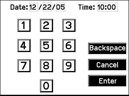
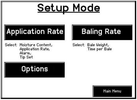
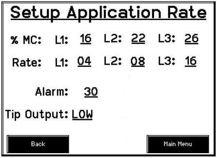
16 Setting up system for initial use In this mode you will setup your initial application rate and baling rate Application rate After pushing the SETUP MODE key in the Main Menu screen, the top screen should appear: On this screen the operator will press the APPLICATION RATE key. Once pressed the SETUP APPLCATION RATE screen will be shown. (bottom left picture) 2. Press any of the underlined numbers to the right of %MC to adjust their figures. The key pad shown on the bottom right will display. Remember level 1 must be lower than level 2 and level 2 must be lower than level 3. Harvest Tec products recommend set points of 16, 22, and 26 % MC levels. These are preset from the factory. Press ENTER to return to previous screen. 3. To change rate of chemical application press any of the underlined numbers to the right of the RATE:. The key pad shown on the bottom right will display. Remember level 1 must be lower than level 2 and level 2 must be lower than level 3. Harvest Tec products recommend rates of 4,8, and 16 lbs/ton (2, 4, and 8 litres/tonne). These rates are preset from the factory. Press ENTER to return to previous screen. IT IS THE OPERATORS RESPONSIBILITY TO FOLLOW THE RECOMMENDATIONS OF THE PRESERVATIVE. ONLY THE OPERATOR CAN APPLY THE PROPER RATE. 4. To set the alarm press on the underlined area. Set the level at which you want the alarm to activate. To turn the alarm off, set level above The TIP OUTPUT should always read LOW for small square balers; only use HIGH for three tie balers. The TIP OUTPUT key allows the operator to select between high and low outputs. 6. Press the OPTION key to adjust the touchscreen between metric and standard units. 7. Next press the BACK key found on the bottom left hand of the screen to return to the previous screen or press MAIN MENU key on the bottom right hand of the screen to return to the opening screen. 16
: to adjust the weight of your bales.")
17 Baling rate After pushing the SETUP MODE key in the Main Menu screen, the top screen should appear: On this screen the operator will press the BALING RATE key. This screen is shown on the bottom left picture shown above. 2. Press the underlined number to the right of AVG Bale Weight (Lbs): to adjust the weight of your bales. The key pad shown on the right side will display. Press any number combination in this screen within the min/max limits. Press the ENTER key to save this information. The information will remain until it is changed again. 3. Press the underlined number to the right of AVG Bale Length (In): to adjust the length of your bales. The key pad shown on the right side will display. Press any number combination in this screen within the min/max limits. Press the ENTER key to save this information. The information will remain until it is changed again. 4. Press the underlined number to the right of EST Baling Time (Sec): to adjust the time it takes to make a bale. The key pad shown on the right side will display. Press any number combination in this screen within the min/max limits. Press the ENTER key to save this information. The information will remain until it is changed again. 5. If the unit will be run with the bale sensors on, then the bale weight and length will need to be inputed. When the sensors are: on, the applicator will calculate your tons per hour. When the Sensors are: off (as shown above), a constant tons per hour ( your inputed bale weight and time) will be used. Press the underlined word to toggle between on or off. 6. Next press the BACK key found on the bottom left hand of the screen to return to the Setup Mode screen, or press the MAIN MENU key on the bottom right hand of the screen to return to the opening screen. 7. Press the OPTION key to adjust the touchscreen between metric and standard units and languages. 17
18 Operating instructions Auto mode will automatically apply product based on both hay moisture content sensed by the star wheels and the operator s presets. (See Setting up system for initial use to change any of these settings). Manual mode will apply preservative to the hay at a fixed rate regardless of the moisture content. Automatic Mode After pushing the AUTOMATIC MODE key in the Main Menu screen, the following screen should appear: Push the START/STOP key to pause the unit while in operation. 2. Push the OVERRIDE key to turn on all three pumps at the same time for full output of the system. Use this mode when going through a short area of wet crop. 3. The moisture content is shown in the upper right hand corner. 4. Baling Rate and Application Rate are shown in the middle. The operator sets the target application rate in the setup mode; the actual rate should be within +/- one pound (litre) when running. The baling rate is also set in Setup Mode. 5. Volume used shown at the bottom of the screen will show accumulated pounds (litres) of preservative used on the go. This number will reset at power down, but remains in the job record screen. NOTE: Initial start-up requires pressing the New Job key in the Job Records screen in order for Volume Used accumulation to be recorded. This only needs to be done once on initial start-up of system and not every time the system is started for operation. (See JOB RECORDS screen) 6. The graph shows the moisture trend from the past 90 seconds in 3 second intervals. 7. This button is your contrast control. Press this button to lighten the screen. When the screen reaches its lightest point, pressing again will return to the darkest setting. 8. Press the MAIN MENU key to return to the opening screen. 18
19 19
20 Manual mode After pushing the MANUAL MODE key in the Main Menu screen, the following screen should appear: Push the START/STOP key to pause the system while in operation. 2. Push the OVERRIDE key to turn on all three pumps at the same time for full output of the system. Use this mode when going through a short area of wet crop. 3. In Manual Mode you can turn the pumps on or off by pressing the underlined area next to the pump numbers. In Manual Mode (regardless of baling rate, moisture, or bale weight) the outputs of the pumps are fixed rates as follows: 2 10 Pump outputs for Three Tie (High): Pump 1 = 40 LBS/HR Pump 2 = 75 LBS/HR Pump 3 = 205 LBS/HR Conventional Square (Low): Pump 1 = 25 LBS/HR Pump 2 = 75 LBS/HR Pump 3 = 145 LBS/HR 4. The moisture content is shown in the upper right hand corner. 5. Baling rate and Application rate are shown in the middle. The output of a pump can be checked by dividing the preset output (shown in step 3, above) by the displayed baling rate. For example, if you are running pump three, by itself for conventional square, your output is 145 lbs/hr. Given the baling rate shown on the above screen of 18 tons/hr, the application rate should be about 8.0 lbs/ton (145 lbs/hr divided by 18 tons/hr). 6. Volume used shown at the bottom of the screen will show accumulated pounds of preservative used on the go. This number will reset at power down, but remains in the job record screen. NOTE: Initial start-up requires pressing the New Job key in the Job Records screen in order for Volume Used accumulation to be recorded. This only needs to be done once on initial start-up of system and not every time the system is started for operation. (See JOB RECORDS on the following page) 7. The baling rate is set in the Setup Mode menu. 8. The graph shows the moisture trend from the past 90 seconds of baling time (one reading every three seconds). 9. This button is your contrast control. Press this button to lighten the screen. When the screen reaches its lightest point, pressing again will return to the darkest setting. 10. Press the Main Menu key to return to the opening screen. 20

21 Job records After pushing the JOB RECORDS key in the Main Menu screen, the following screen should appear: The job number will be displayed in the top left corner and will move to the next job when the NEW JOB key is pressed. The current job being viewed will always read "Job #: 0". Product used and average moisture content will be reset when the NEW JOB key is pressed. The job records screen will store up to 63 jobs and will allow you to access previous jobs by using the up and down arrows found on the right side of the screen. 2. Scrolling through previous jobs is done by pressing the UP or Down keys. 3. Every time the NEW JOB key is pressed the accumulated pounds on auto and manual modes will be reset to zero. After 63 jobs have been stored, the next time the NEW JOB key is pressed the system will start over with job one and the old job will be replaced. 4. Highest moisture content will display moistures up to 33%. Any moisture recorded higher than 33 % will register only as 99%. 5. To return the opening screen, press the MAIN MENU key. NOTE: Initial start-up requires pressing the New Job key in the Job Records screen in order for Volume Used accumulation to be recorded. This only needs to be done once on initial start-up of system and not every time the system is started for operation. 21
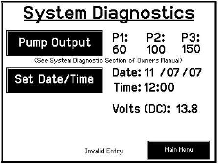
22 Diagnostics After pushing the DIAGNOSTICS key in the Main Menu screen, the following screen should appear: The diagnostic mode will automatically check the pump output and performance of the three pumps. It is recommended to use this mode daily to ensure proper system performance. Acceptable ranges for output: Low output tips: Pump 1 = LBS/HR Pump 2 = LBS/HR Pump 3 = LBS/HR High output tips: Pump 1 = LBS/HR Pump 2 = LBS/HR Pump 3 = LBS/HR 1. Once the screen is displayed, press the PUMP OUTPUTS key. The machine will cycle all three of the pumps for 15 seconds. After the cycles are complete, the system will display a number next to each pump number. 2. If the system displays within the listed range. A. The system is operating correctly. If the system displays higher than the listed range, some common problems could be: A. Leak in line. Inspect lines thoroughly. B. Tip missing. Check for lost or broken tip on spray shield. C. Tip worn. Replace tip. D. High tractor voltage. If the system displays lower than the listed range, some common problems could be: A. Make sure there is preservative in the tank and ball valve is in the open position. B. Air in lines. Pump will not prime. Check for leak in lines, or defective check valve. C. Pump is working, but not producing desired output. Pump needs to be rebuilt. D. Main filter plugged. Check filter by tank and clean if necessary. E. Tip or tip screen plugged. Check both tip and tip screen and clean if necessary. F. Kink in hose. Straighten or replace hose. G. Voltage from tractor is low. Check power cord with multimeter for 12 volts at baler mounted processor. Clean connections on battery. Dielectric grease connections at baler mounted processor and at hitch connection. H. Pump is defective. Rebuild pump if motor runs smoothly. Replace pump if motor is bad. I. Defective flow meter. Only if all pumps run, product is applied, and all numbers read To set date and time, press the SET DATE/TIME key. In the next screen enter the date (month, day, year format) followed by the time. When done press the ENTER key. NOTE: The clock uses military (or 24 hour) time. 4. The voltage should be between 12.0 to 14.5 volts for the system to work properly. If voltage is not in this range check all power cord connections and the tractors charging system. 5. When done in this mode, press the MAIN MENU key. 22
23 Common questions about the 445, 450 & How do I turn the system on/off? To turn the system ON, simply press anywhere on the right side of the screen followed by pushing the Press to Start key. To turn the system OFF, return to the Main Menu screen and press the POWER OFF key 2. How to get in the LBS/TON, MC%, and TONS/HR screens? In the Main Menu press the SETUP MODE key. From this screen you can change your application rates and how much product is applied. See SETTING UP FOR INITIAL USE for a detailed explanation of this process. 3. The unit is stuck in the Application Rate screen. In the Application Rate screen, level 1 must be less than level 2, and level 2 must be less than level 3. For example, if level 1 is set at 16, level 2 must be set at 17 or higher, and level 3 must be set higher than level How does OVERRIDE work? Override turns on all three pumps at full output. The pumps will remain at full output until the operator turns these pumps off by pressing the OVERRIDE key again. 5. The flow meter reading is more or less than the programmed level set in the box. Some variation in flow meter readings compared to the programmed set point is normal due to factory tolerances on the pump motors as well as varying tractor voltages inputted to the control box. The flow meter reading is an accurate measure of how much product is actually being applied. The set points then will need to be adjusted if you want to attain a different flow meter reading. 6. Why don t all the pumps turn on even at higher application rates? The selections of what pumps turn on when are automatically controlled by the control box s flow rate look up chart. Thus, not all the pumps turn on at once and the combination of what pumps turn on when is automatically controlled by the software. If you want to make sure all three pumps are working, go to the Diagnostics screen and run pump outputs.. 7. The moisture content displays LO or HI all the time. When the moisture content display does not change frequently while baling, there is likely a faulty star wheel connection. One of the first places to check is inside the white star wheel block. Check to see if the electronic swivel is in the star wheel shaft and check to see that the star wheel shaft is not working out of the block. Also, check all star wheel wires and connectors to see if there is a continuity or grounding problem. 8. Should the battery connections be removed before jump starting or charging a battery? Yes. Anytime the tractor will have voltage going up rapidly the connections should be removed. 23
24 Trouble shooting checks: Problem Possible cause(s) Solution(s) Pump will not run. 1. No voltage to Baler Mounted Processor. 1. Check for short, low voltage, and replace fuse if necessary. 2. Pump locked up. 2. Clean or rebuild pump if motor is OK. 3. Damaged wire. 3. Repair damaged wire. Pump runs but will not prime. 1. Air leak in intake. 1. Tighten fittings on intake side. 2. Clogged intake. 2. Clean. 3. Restricted outlet. 3. Check and clean tips. 4. Check valve on outlet 4. Clean or repair check valve. stuck closed. 5. Dirt inside pump. 5. Replace pump check valve. Pump does not develop enough 1. Air leaks or clogs on inlet 1. Tighten or clean filter bowl assembly. output. side. 2. Pump worn or dirty. 2. Rebuild pump. Moisture reading errors (high or low) Moisture readings erratic. Flow meter readings do not match up with product usage. Product is less than actual product used. 1. Wire disconnected or bad connection between star wheels and baler mounted processor. 2. Low power supply to baler mounted processor. 3. Wet hay over 32% moisture 4. Ground contact with one or both star wheels and baler mounted processor. 5. Short in wire between star wheels and baler mounted processor. 6. Check hay with hand tester to verify. 1. Test bales with hand tester to verify that cab monitor has more variation than hand tester. 2. Check all wiring connections for corrosion or poor contact. 3. Check power supply at tractor. Voltage should be constant between 12 and 14 volts Reconnect wire. 2. Check voltage at box. (Min of 12 volts required.) See Diagnostics section of manual. 4. Reconnect. 5. Replace wire. 6. Contact Harvest Tec if conditions persist. 2. Apply dielectric grease to all connections. 3. Install voltage surge protection on tractors alternator. 1. Voltage supplied to meter 1. Check for a min of 6 volts supplied at is less than 6 volts. baler mounted processor. 2. Wiring short in signal to 2. Inspect wire and replace if necessary. baler mounted processor. 3. Clog in meter. 3. Back flush with water. DO NOT USE AIR. 4. Using product other than 4. Catch and weigh product to check Harvest Tec outputs.
25 Product shown is more than actual product used. System leaks product out of tips after shut down. Terminal reads under or over power. System always displays "End of Row Pause". System does not pause at the end of a row. Bale rate displays zero. Display will not power up. Display is too dark or light Display says waiting for BMP Backup fuse 1. High voltage supplied to the meter. 2. Light interference with meter. 1. Check voltage at baler mounted processor. Max of 18 volts. 2. Reflection into meter can cause a high reading. Move meter or protect from sunlight. 3. Air leak in intake. 3. Look for air bubbles in line. Replace line or other defective area that is allowing air into the system. 4. Using product other than Harvest Tec 1. Dirty or defective check valves. 1. Verify with multi-meter actual voltage. Voltage range should be between volts. 1. Flow meter connector plug is plugged into Hay Indicator port on Baler Mounted Processor. 4. Catch and weigh product to check outputs. 1. Clean or Replace. 1. Clean connections and make sure applicator is hooked to battery. See Diagnostics section of manual. 1. Switch ports. 1. Short in cable. 1. Replace cable. 1. Bale rate sensors are reversed. 2. Short in cable. 1. Display connector plug and bale rate sensors plug are switched on the Baler Mounted Processor. 2. Short in display cable. 1. Change in temperature or light conditions. 2. Display and BMP not communicating. 1. Display and BMP not communicating. 1. Switch the sensors next to the star wheel. 2. Replace cable. 1. Switch plugs. 2. Replace cable. 1. Use the monitors contrast control. 2. Disconnect 12 volt power cable at hitch. DO NOT DISCONNECT DISPLAY CABLE. Wait 5 minutes and reconnect. 1. Disconnect 12 volt power cable at hitch. DO NOT DISCONNECT DISPLAY CABLE. Wait 5 minutes and reconnect. The Model 462 is equipped with a backup system if your display is not functioning. This function is intended for use only as a temporary means for application and not as a way to apply preservative over multiple fields or for a lengthy amount of time. The baler mounted processor has a location for a backup fuse on the same side as the pump and flow meter harness that bypasses all other system inputs and applies preservative using one pump (Pump Three) at a constant lbs/hour shown below. These values are based upon on input voltage of 13.5 DC. Insert at least a 10 amp up to 20 amp fuse (3 AG style) into the backup fuse port to activate the bypass. The system will not turn off or pause until the fuse is removed. The main fuse must also be functional for the backup fuse to work. Tip Set Output (lbs/hour) 462 High 180 Low

26 Wiring diagrams A. Main power connector mounted on battery Pin 1 Red + 12 V input from tractor supply Pin 2 Black Ground from tractor supply Pin 3 Not used B. Main power connector mounted on BMP Pin 1 Red + 12 V input from tractor supply Pin 2 Black Ground from tractor supply Pin 3 Not used C. Pump connection colors Pin 1 Black with orange markings Pump 1 ground Pin 2 Black with green markings Pump 2 ground Pin 3 Black with yellow markings Pump 3 ground Pin 4 Not used Pin 5 Orange with black markings Pump 1 positive Pin 6 Green with black markings Pump 2 positive Pin 7 Yellow with black markings Pump 3 positive D. Flow meter connection on BMP Pin 1 White 5-12 V (+) supply Pin 2 Green Ground Pin 3 Brown Signal Pin 4 Black Shield E. Connector for Hay Indicator option on BMP Note: Hay indicators are an option that will turn the system on and off automatically as hay enters the pickup of the baler. Pin 1 Red +12V Pin 2 Black Ground Pin 3 White Signal wire Pin 4 Not used 26
27 27

28 F. Bale rate sensors on BMP Pin1 Brown Sensor power Pin2 Black Signal for front prox. sensor Pin3 Blue Sensor ground Pin4 Black Signal for back prox. sensor G. Star wheel connector mounted on BMP Pin 1 Brown Star wheel input 1 Pin 2 Blue Star wheel input 2 Pin 3 Brown Diagnostic 1 Pin 4 Blue Diagnostic 2 Pin 5 Silver Shield Pin 6 Silver Shield Pin 7 Not used Pin 8 Not used Pin 9 Not used H. Communication harness display to hitch Pin 1 Red Power to display Pin 2 Black Ground to display Pin 3 Blue Comm channel OH Pin 4 Orange Comm channel OL I. Communication harness hitch to baler mounted processor Pin 1 Red Power to display Pin 2 Black Ground to display Pin 3 Blue Comm channel OH Pin 4 Orange Comm channel OL 28


29 Maintenance If you are unsure how to perform any of the maintenance steps have your local authorized dealer perform the tasks. Maintenance Schedule Daily 10 hrs 400 hrs Weekly Monthly Season Diagnostics X X Filter bowl cleaning X X Tips & tip screen cleaning X X Tank lid cleaning X X Dielectric grease connections X X Rebuild pumps X Battery connections X X Check valves X Visually inspect hoses X X Diagnostics: Follow the instructions in this manual to run the Diagnostics mode. Filter bowl cleaning: The filter bowl is located in front of the applicators tank and is connected to the ball valve. Before cleaning the filter bowl all personal protective equipment must be worn (Face shield or goggles, chemically resistant apron, boots, and gloves). Verify that the ball valve located next to the pump is turned off. Locate the filter bowl on the side of the pump manifold (A). Unscrew the bottom section of the filter bowl and remove the strainer. (B) Clean off any debris and soak in warm water with a mild soap if necessary. Once the screen is clean reinstall by following the directions in reverse. A B 29

30 Tips & tip screen cleaning: Before cleaning the tips and screens all personal protective equipment must be worn (Face shield or goggles, chemically resistant apron, boots, and gloves). Verify that the ball valve located next to the pump is turned off. Disconnect spray shield from hangers if possible or remove tips in place. Remove the tip, and screen. Some models may require a wrench to remove. Clean off any debris and soak tip and screen in warm water with a mild soap if necessary. Once the tips and screens are cleaned reinstall by following the directions in reverse. Tank lid cleaning: Before cleaning the tank lid all personal protective equipment must be worn (Face shield or goggles, chemically resistant apron, boots, and gloves). The tank lid is located on the top of the tank. Use the supplied handle on the tank to secure your person and use the other hand to remove any debris from the top of the tank. Unscrew the tank lid and bring down ground level. Use compressed air clean out the tank screen (D). If the screen cannot be thoroughly cleaned with compressed air, replace fitting ( B3). Once the screen is cleaned reinstall the cover. D Dielectric grease connections: Disconnect all harnesses on the applicator, clean the connections, and repack with dielectric grease. Rebuild pumps: If Diagnostic or Manual mode show that the pumps are running lower than normal, a pump rebuild may be necessary. To do this rebuild the pump must be removed from the pump manifold. Pump rebuild is part no A service pack that includes pump rebuilds and check valves is available from your local dealer. Verify that the ball valve is turned off. Before working around the pumps all personal protective equipment must be worn (Face shield or goggles, chemically resistant apron, boots, and gloves). Remove pump from manifold. Follow rebuild instructions supplied with pump rebuild kit. Reinstall after rebuild is complete. Battery connections: Follow the batteries safety warnings and clean the battery connections. If the connections cannot be cleaned, replace harness. Check Valves: Before servicing the check valves all personal protective equipment must be worn (Face shield or goggles, chemically resistant apron, boots, and gloves). Verify the ball valve is turned off before service the check valves. Replace the intake check valves by the pumps ( F) and the discharge check valves by the tip ( VB). Miscellaneous maintenance: 30
31 1. Depending on the product being used, the system may need to be flushed with water at a regular interval (consult with manufacturer of the chemical.) If Harvest Tec product is being used, flushing is not necessary. 2. Although the pump can run dry, extended operation of a dry pump will increase wear. Watch the preservative level in the tank. 3. If you are using bacterial inoculants, flush your system daily after every use. Winter Storage 1. Thoroughly flush the system with water. 2. Remove the filter bowl and run dry until the water has cleared out of the intake side. 3. Remove the red plug from the bottom of the pump, drain, and run the pump for 30 seconds or until it is dry. 4. Drain all lines on the outlet side. 5. Never use oils or alcohol based anti-freeze in the system. 6. For spring start-up, if the pump is frozen, turn off the power immediately to avoid burning the motor out or blowing a fuse. The pump head can be disassembled and freed or rebuilt in most cases. Check the fuses after the pump has been freed. 7. Disconnect power from the Precision Information Processor. 8. Remove display from tractor and store in a warm, dry place. 31


32 Harvest Tec model 445 base kit Ref# Description Part # Qty Ref# Description Part # Qty 1 Tank Cap C 1 5 Tank Tank Cap Gasket CG 1 6 Saddle Tank Strap Mounting Bracket Stub Pipe Tank Fitting Harvest Tec model 450 base kit Ref# Description Part # Qty Ref# Description Part # Qty 1 Tank Saddle Straps Tank Cap C 1 3 Tank Fitting Tank Gasket CG 1 NP PIP mount BPM 2 32

33 Harvest Tec model 451 base kit Ref Description Part # Qty 1 Tank SQ 1 2 Tank Saddle C 1 3 Tank Straps Short Strap Base CC 2 5 Tank fitting Mounting Bracket Door Latch CL 1 8 Tank Lid H 1 NP Long Strap Base CD 2 NP Not Pictured 33

34 Parts breakdown for pump manifold c 4 12a b Ref# Description Part# Qty 1 Pump plate D 1 2 Mounting Bracket C 1 3 Pump H 3 4 Street elbow fitting 003-SE Nipple fitting 003-M Check valve F 3 7 Elbow fitting 003-EL Tee fitting 003-T3812HB 2 9 Flow meter assembly A 1 10 Straight fitting 003-A Elbow fitting 003-JEL Filter bowl assembly a Filter bowl only F 1 12b Filter bowl gasket D 1 12c Filter bowl screen B 1 13 Nipple fitting 003-M Ball valve Street elbow fitting 003-SE Hose clamp Hose clamp (Flow Meter) Pump Cable Z 1 NP Pump rebuild kit (1 per pump) NP Elbow 003-EL NP Union 003-M1212F 1 NP Not Pictured 34
 006-4642K 2 11 Moisture cable 006-4640K 1 2 Dust Seal (per side) w/006-4642k 1 12 Bale rate sensor 006-7303S 2 3 Snap Ring (per")

 002-9016 002-9016B 002-9016G 15ft 15ft 15ft Hose assembly (3 hose assembly) 030-9016SS 1 2 ½ Hose (tank to filter) 002-9001")
35 Parts breakdown for star wheel sensor, bale rate sensor & hoses Ref Description Part# Qty Ref Description Part# Qty 1 Washer (per side) K 2 11 Moisture cable K 1 2 Dust Seal (per side) w/ k 1 12 Bale rate sensor S 2 3 Snap Ring (per side) w/ k 2 13 Bale rate sensor harness H 1 4 Swivel A Bale rate sensor assembly Star Wheel E 2 14 Bale rate sensor holder SS 1 6 Insert w/ Ref # 5 2 NP Bale rate sensor extension EXT 1 7 Wiring grommet A 2 8 Star wheel block A 2 9 Plug Fitting 003-F Block Cover B Star wheel assembly Ref Description Part# Qty 1 Triple weld hose (from pumps to tips) B G 15ft 15ft 15ft Hose assembly (3 hose assembly) SS 1 2 ½ Hose (tank to filter) ft 35

36 Parts breakdown for drain fill kit (model 451 & 450 only) Ref # Description Part # Qty Ref # Description Part # Qty 1 Straight Fitting 003-A Male Coupler G 1 2 Elbow 003-EL Valve Holder H 1 3 Hose Clamps Ball valve Female Coupler A 1 8 Jiffy Clip
 006-4660L 5 Communication harness (tractor)")
37 Parts breakdown for control box and wiring harnesses Ref. Description Part# 1 Power lead tractor A 2 Power lead baler K 3 Baler mounted processor SS 4 Communication harness (baler) L 5 Communication harness (tractor) N 6 Ram mount H Terminal NP Dust Plugs PLUGS NP Suction cup mount SCM 37

38 Harvest Tec model 4409B installation kit Ref Description Part# Qty Description Part# Qty 1 Nozzle strap Tip 004-T SS 2 2 Tee 003-TT14SQ 1 Tip 004-T SS 1 3 Straight fitting 003-A Tip 004-T11003-SS 1 4 Elbow 003-EL1414F 3 Hose ft 5 Hose clamp Check valve XB 3 7 Female disconnect H 3 8 Washer W 3 9 Tip screen Hose bracket Female coupler G 3 12 Elbow 003-EL U bolt A 2 14 Mounting bracket Inside reach rod Outside reach rod

39 Harvest Tec model 4410B installation kit Ref Description Part# Qty Description Part# Qty 1 Spray shield Tip 004-T SS 2 2 Straight fitting 003-A Tip 004-T SS 1 3 Tee 003-TT14SQ 1 Tip 004-T11003-SS 1 4 Hose ft 5 Elbow 003-SE14F 1 6 Elbow 003-EL1414F 2 7 Hose clamp Check valve XB 3 9 Female disconnect H 3 10 Washer W 3 11 Tip strainer Hose bracket Female coupler G 3 14 Elbow 003-EL U bolt A 2 16 Mounting bracket Inside reach rod Outside reach rod

40 Harvest Tec model 4415B installation kit Ref Description Part# Qty Description Part# Qty 1 Spray shield C 1 Tip HCX4 1 2 Drill guide 003-M3814NB 3 Tip HCX9 1 3 Elbow 003-EL3814NB 3 Tip HCX Tip strainer Nozzle cap 004-BC U bolt A 2 7 Mounting bracket Outside reach rod Inside reach rod Hose bracket B 2 11 Jiffy clip Jiffy clip Hose clamp Tip box Knob

41 Harvest Tec model 4485B installation kit Ref Description Part# Qty Ref Description Part# Qty 1 Shield holder B 2 Tip 004-T SS 2 2 Spray shield A 1 Tip 004-T SS 1 3 Elbow 003-SE14F 1 Tip 004-T11003-SS 1 4 Straight fitting 003-A Hose ft 6 Elbow 003-EL1414F 2 7 Tee 003-TT14SQ 1 8 Hose clamp Check valve XB 3 10 Female disconnect H 3 11 Washer W 3 12 Tip strainer Hose bracket Female coupler G 3 15 Elbow 003-EL Leg support C 2 17 Saddle leg B 2 41

42 Harvest Tec model 4502B installation kit Ref Description Part # Qty Description Part # Qty 1 Straight fitting 003-A Tip 004-T SS 2 2 Tee 003-TT14SQ 1 Tip 004-T SS 1 3 Elbow 003-SE14F 1 Tip 004-T11004-SS 1 4 Elbow 003-EL1414F 2 5 Hose ft 6 Hose clamp Check valve XB 3 8 Female disconnect H 3 9 Washer W 3 10 Tip strainer Hose bracket Female coupler G 3 13 Elbow 003-EL Lynch pin Spray shield G 1 16 Shield holder I 2 17 Twine diverter (prox) Twine diverter Saddle leg B

43 Harvest Tec model 4506B installation kit Ref Description Part # Qty Description Part# Qty 1 Straight fitting 003-A Tip 004-T SS 2 2 Tee 003-TT14SQ 1 Tip 004-T SS 1 3 Elbow 003-EL1414F 2 Tip 004-T11004-SS 1 4 Elbow 003-SE14F 1 5 Hose ft 6 Hose clamp Check valve XB 3 8 Female disconnect H 3 9 Washer W 3 10 Tip strainer Hose bracket Female coupler G 3 13 Elbow 003-EL Lynch pin Spray shield G 1 16 Shield holder H 2 17 Twine diverter (prox) Twine diverter Saddle leg B 2 43

 001-4644 1 18 Twine diverter 001-4645 1 19 Saddle leg")
44 Harvest Tec model 4507B installation kit Ref Description Part # Qty Description Part# Qty 1 Straight fitting 003-A Tip 004-T SS 2 2 Tee 003-TT14SQ 1 Tip 004-T SS 1 3 Elbow 003-SE14F 1 Tip 004-T11004-SS 1 4 Elbow 003-EL1414F 2 5 Hose ft 6 Hose clamp Check valve XB 3 8 Female disconnect H 3 9 Washer W 3 10 Tip strainer Hose bracket Female coupler G 3 13 Elbow 003-EL Lynch pin Spray shield G 1 16 Shield holder J 1 17 Twine diverter (prox) Twine diverter Saddle leg B 2 44
45 Notes: 45
46 WARRANTY AND LIABILITY AGREEMENT Harvest Tec, Inc. will repair or replace components that are found to be defective within 12 months from the date of manufacture. Under no circumstances does this warranty cover any components which in the opinion of Harvest Tec, Inc. have been subjected to negligent use, misuse, alteration, accident, or if repairs have been made with parts other than those manufactured and obtainable from Harvest Tec, Inc. Our obligation under this warranty is limited to repairing or replacing free of charge to the original purchaser any part that in our judgment shows evidence of defective or improper workmanship, provided the part is returned to Harvest Tec, Inc. within 30 days of the failure. Parts must be returned through the selling dealer and distributor, transportation charges prepaid. This warranty shall not be interpreted to render Harvest Tec, Inc. liable for injury or damages of any kind, direct, consequential, or contingent, to persons or property. Furthermore, this warranty does not extend to loss of crop, losses caused by delays or any expense prospective profits or for any other reason. Harvest Tec, Inc. shall not be liable for any recovery greater in amount than the cost or repair of defects in workmanship. There are no warranties, either expressed or implied, of merchantability or fitness for particular purpose intended or fitness for any other reason. This warranty cannot guarantee that existing conditions beyond the control of Harvest Tec, Inc. will not affect our ability to obtain materials or manufacture necessary replacement parts. Harvest Tec, Inc. reserves the right to make design changes, improve design, or change specifications, at any time without any contingent obligation to purchasers of machines and parts previously sold. Revised 01/03/06 46
47 For Technical assistance: HARVEST TEC, INC. P.O. BOX HARVEY STREET HUDSON, WI PHONE: FAX:
Model 446, 447 & & 55 gallon Preservative Applicators
 Operation Manual Model 446, 447 & 449 25 & 55 gallon Preservative Applicators #00-0446-447-449-OPR Revised /3 Introduction Congratulations on purchasing a Harvest Tec Model 446 or 447 or 449 applicator.
Operation Manual A. Touch Screen Display (TSD) for 600 Series A-OPR 11/13
 for 600 Series A-OPR 11/13") Operation Manual 030-5670A Touch Screen Display (TSD) for 600 Series 030-5670A-OPR 11/13 1 (intentionally blank) 2 Harvest Tec Touch Screen Display Table of Contents 5670A PAGE Introduction 4 Safety 4
Operation Manual 030-5670A Touch Screen Display (TSD) for 600 Series 030-5670A-OPR 11/13 1 (intentionally blank) 2 Harvest Tec Touch Screen Display Table of Contents 5670A PAGE Introduction 4 Safety 4
Small Square Baler Models
 Operation Manual Small Square Baler Models 25 & 55 gallon Preservative Applicators 444T-445T-450T-451T-OPR 4/16 (intentionally blank) 2 Small Square Baler Models Operation Table of Contents Page Introduction
Model 440, 441, 442 & 448
 Operation Manual Model 440, 44, 44 & 448 & gallon Preservative Applicator 440-44-44-448-OPR /6 (intentionally blank) Harvest Tec 440, 44, 44 & 448 OPERATION Table of Contents Page Model Reference Introduction
Installation Manual. Model 445, 450 & & 200 Liter Automatic Preservative Applicator Metric INST-M 9/16
 Installation Manual Model 445, 450 & 451 100 & 200 Liter Automatic Preservative Applicator Metric 445-451-450-INST-M 9/16 2 Harvest Tec 445, 451 & 450 Installation Table of Contents PAGE Introduction 4
OWNER S MANUAL. Model 840. Dye Sprayer Marking System 840 7/16
 OWNER S MANUAL Model 840 Dye Sprayer Marking System 840 7/16 HARVEST TEC 840 TABLE OF CONTENTS PAGE INTRODUCTION & TOOLS NEEDED 3 INSTALLATION OF DYE SPAYER TANK & PLUMBING 4-10 1. INSTALLATION OF MOUNTING
OWNER S MANUAL. Model GALLON SPRAYER REVISION 11/11
 OWNER S MANUAL Model 675 100 GALLON SPRAYER 010-0675 REVISION 11/11 TABLE OF CONTENTS PAGE INSTALLATION INSTRUCTIONS FOR JOHN DEERE 6000 SERIES 3 INSTALLATION OF FENDER SUPPORT 3 INSTALLATION OF TANK AND
Model 444T, 445T, 450T & 451T
 Installation Manual Model 444T, 445T, 450T & 451T 100 & 200 Liter Automatic Preservative Applicator Metric 444T-445T-451T-450T-15-INST-M 8/16 Harvest Tec 444T, 445T, 451T & 450T Installation Table of Contents
Operation Manual. Model & 110 Gallon Preservative Applicator OPR 10/15
 Operation Manual Model 9 00 & 0 Gallon Preservative Applicator 9--OPR 0/ (intentionally blank) Harvest Tec Model 9 Operation Table of Contents Page Introduction Installation Kit Reference Chart - Safety
Operation Manual. Electronic XHI System. High Output Electronic Preservative Applicator Metric. Electronic XHI-17-OPR-M 4/17
 Operation Manual Electronic XHI System High Output Electronic Preservative Applicator Metric Electronic XHI-7-OPR-M 4/7 DECLARATION OF INCORPORATION MANUFACTURER: Harvest Tec Inc. 282 Harvey St. P.O. Box
Installation Manual. Model 300SS-M. Moisture Only Kit for Small Square Balers 300SS-16-INST-M 3/17 1
 Installation Manual Model 300SS-M Moisture Only Kit for Small Square Balers 300SS-16-INST-M 3/17 1 (intentionally blank) 2 300SS Installation Manual Table of Contents Page Introduction 4 System Requirements
OWNER S MANUAL. Model 545, 550 & & 55 Gallon Automatic Preservative Applicator # REVISED 12/12
 OWNER S MANUAL Model 545, 550 & 551 25 & 55 Gallon Automatic Preservative Applicator #010-0551 REVISED 12/12 HARVEST TEC 545, 550 & 551 TABLE OF CONTENTS PAGE INSTALLATION KIT REFERENCE CHART 4 TOOLS NEEDED
Installation Manual. Model 664. Automatic Preservative Applicator INST 5/14
 Installation Manual Model 664 Automatic Preservative Applicator 010-0664-INST 5/14 (intentionally blank) 2 Harvest Tec Model 664 Installation Table of Contents PAGE Introduction 4 System Requirements 4
Operation Manual. 300 Series Small Square Baler Models. 25 & 55 gallon Preservative Applicators OPR 4/18
 Operation Manual 300 Series Small Square Baler Models 25 & 55 gallon Preservative Applicators 344-345-350-351-OPR 4/18 1 (intentionally blank) 2 Small Square Baler Models Operation Table of Contents Page
Operation Manual. Model 696J-M. 110 Gallon Preservative Applicator 696J-16-M-OPR-BLE 10/16
 Operation Manual Model 696J-M 110 Gallon Preservative Applicator 696J-16-M-OPR-BLE 10/16 DECLARATION OF INCORPORATION MANUFACTURER: Harvest Tec Inc. 2821 Harvey St. P.O. Box 63 Hudson, WI 54016, U.S.A.
696K & 665K Supplement For Krone BP 4x4 & HDP balers
 Supplement Manual 696K & 665K Supplement For Krone BP 4x4 & HDP balers #010-0696K REVISED 4/14 SUPPLEMENT INDEX PAGE INSTALLATION KIT REFERENCE CHART 3 INSTALLATION OF THE APPLICATOR 4-9 1. Installation
OWNER S MANUAL. Model 474. Hay Indicator Kit 474 INST & OPR 1/16
 OWNER S MANUAL Model 474 Hay Indicator Kit 474 INST & OPR 1/16 1 TABLE OF CONTENTS PAGE Overview 3 Tools Needed 3 Mounting Instructions for Hay Indicator on Baler 4-9 Alignment of the Sensors 4 Installation
Operation Manual. Model 696M-M. 110 Gallon Preservative Applicator 696M-16-M-OPR-BLE 9/16
 Operation Manual Model 696M-M 110 Gallon Preservative Applicator 696M-16-M-OPR-BLE 9/16 DECLARATION OF INCORPORATION MANUFACTURER: Harvest Tec Inc. 2821 Harvey St. P.O. Box 63 Hudson, WI 54016, U.S.A.
Installation Manual. Model 600. Moisture Sensor Kit for Large Square Balers 600-INST 4/16
 Installation Manual Model 600 Moisture Sensor Kit for Large Square Balers 600-INST 4/16 (intentionally blank) 2 Harvest Tec Model 600 Installation Table of Contents PAGE Introduction 4 System Requirements
OWNER S MANUAL. Model 9214 HIGH OUTPUT 12 VOLT TRANSFER PUMP /06 10/17
 OWNER S MANUAL Model 9214 HIGH OUTPUT 12 VOLT TRANSFER PUMP 9214 5/06 10/17 Introduction Congratulations on purchasing a Harvest Tec Model 9214 transfer pump. This system is designed to transfer Harvest
Operation Manual. 300 Series Round Baler Models. 25 & 55 gallon Preservative Applicators C-347U OPR-Imp & Metric 4/19
 Operation Manual 300 Series Round Baler Models 25 & 55 gallon Preservative Applicators 337-34-347-347C-347U-349--OPR-Imp & Metric 4/9 DECLARATION OF INCORPORATION MANUFACTURER: Harvest Tec Inc. 22 Harvey
Model 300RB & 300RBC-M
 Installation Manual Model 300RB & 300RBC-M Moisture Only Kit for Round Balers 300RB & 300RBC-16-INST-M 3/17 1 (intentionally blank) 2 300RB Installation Manual Table of Contents Page Introduction 4 System
HARVEST TEC, INC MODEL 464 AUTOMATIC HAY PRESERVATIVE APPLICATOR FOR LARGE SQUARE BALERS
 HARVEST TEC, INC MODEL 464 AUTOMATIC HAY PRESERVATIVE APPLICATOR FOR LARGE SQUARE BALERS HARVEST TEC, INC PO BOX 63 HUDSON, WI 54016 EMAIL: info@harvesttec.com 010-0464 REV 12/03 1 Table of Contents Installation
Installation Manual. Model 337-M. 25 Gallon Automatic Preservative Applicator INST-M 3/17
 Installation Manual Model 337-M 25 Gallon Automatic Preservative Applicator 337-16-INST-M 3/17 1 DECLARATION OF INCORPORATION MANUFACTURER: Harvest Tec Inc. 2821 Harvey St. P.O. Box 63 Hudson, WI 54016,
Installation Manual. Model 347U-M. 25 Gallon Automatic Preservative Applicator 347U-16-INST-M 5/17
 Installation Manual Model 347U-M 25 Gallon Automatic Preservative Applicator 347U-16-INST-M 5/17 1 DECLARATION OF INCORPORATION MANUFACTURER: Harvest Tec Inc. 2821 Harvey St. P.O. Box 63 Hudson, WI 54016,
Model 601A, 700, 701. Installation Manual. Microwave Moisture Bale Chute System & Pre-Compression Chamber System
 Installation Manual Model 601A, 700, 701 Microwave Moisture Bale Chute System & Pre-Compression Chamber System 601A, 700, 701-17-INST Imp&Metric 11/17 1 (intentionally blank) 2 601A, 700, 701 Installation
OWNER S MANUAL. Model 565 Automatic Preservative Applicator REVISED 11/11
 OWNER S MANUAL Model 565 Automatic Preservative Applicator 010-0565 REVISED 11/11 2 HARVEST TEC 565 TABLE OF CONTENTS PAGE INSTALLATION KIT REFERENCE CHART 5 TOOLS NEEDED 5 INSTALLATION OF APPLICATOR 6-46
Installation Manual. Model 600. Moisture Sensor Kit for Large Square Balers INST-Imp&Metric 5/18
 Installation Manual Model 600 Moisture Sensor Kit for Large Square Balers 600-17-INST-Imp&Metric 5/18 DECLARATION OF INCORPORATION MANUFACTURER: Harvest Tec Inc. 2821 Harvey St. P.O. Box 63 Hudson, WI
Installation Manual. Model 697BB. 115 Gallon Preservative Applicator For New Holland BigBaler and Case IH LB BB-16-INST (Imp&Metric) 11/18
 11/18") Installation Manual Model 697BB 115 Gallon Preservative Applicator For New Holland BigBaler and Case IH LB 4 697BB-16-INST (Imp&Metric) 11/18 DECLARATION OF INCORPORATION MANUFACTURER: Harvest Tec Inc.
Installation Manual Model 697BB 115 Gallon Preservative Applicator For New Holland BigBaler and Case IH LB 4 697BB-16-INST (Imp&Metric) 11/18 DECLARATION OF INCORPORATION MANUFACTURER: Harvest Tec Inc.
Installation Manual. Model & 110 Gallon Preservative Applicator INST-Imp&Metric 1/19
 Installation Manual Model 696 100 & 110 Gallon Preservative Applicator 696-16-INST-Imp&Metric 1/19 DECLARATION OF INCORPORATION MANUFACTURER: Harvest Tec Inc. 2821 Harvey St. P.O. Box 63 Hudson, WI 54016,
PPM EO-100 TM. Operation Manual
 PPM EO-100 TM Open Loop Electric Prewet Power Module Operation Manual Rev A Page 1 2/23/2010 Copyright 2008 by Cirus Controls, LLC. All Rights Reserved. No part of this material may be reproduced in any
180 Lake Ave North Paynesville, MN Phone: (320) MASTER MANUFACTURING MASTER GARDNER
 MASTER MANUFACTURING MASTER GARDNER") 180 Lake Ave North Paynesville, MN 56362 Phone: (320) 340-6464 www.master-mfg.com MASTER MANUFACTURING MASTER GARDNER Part Number PCD-E3-009B-MM July 2017 Note: Do not return product to the distributor/dealer
180 Lake Ave North Paynesville, MN 56362 Phone: (320) 340-6464 www.master-mfg.com MASTER MANUFACTURING MASTER GARDNER Part Number PCD-E3-009B-MM July 2017 Note: Do not return product to the distributor/dealer
180 Lake Ave North Paynesville, MN Phone: MASTER MANUFACTURING MASTER GARDNER
 180 Lake Ave North Paynesville, MN 56362 Phone: 1-800-864-1649 www.master-mfg.com MASTER MANUFACTURING MASTER GARDNER Part Number PCD-E3-009B-MM Rev 2 Dec. 2012 Note: Do not return product to the distributor/dealer
OWNER S MANUAL. Model: LG-30-TRL ( ) (30 Gallon Lawn & Garden Trailer Sprayer)
 (30 Gallon Lawn & Garden Trailer Sprayer)") OWNER S MANUAL Model: LG-30-TRL (5302317) (30 Gallon Lawn & Garden Trailer Sprayer) Technical Specifications 30 Gal. Corrosion-Resistant Polyethylene Tank 12 Volt Diaphragm Pump, 2.1 g.p.m. 60 psi 15 Ft.
OWNER S MANUAL Model: LG-30-TRL (5302317) (30 Gallon Lawn & Garden Trailer Sprayer) Technical Specifications 30 Gal. Corrosion-Resistant Polyethylene Tank 12 Volt Diaphragm Pump, 2.1 g.p.m. 60 psi 15 Ft.
KJ4000LW Operating Instructions & Parts Manual NSN
 KJ4000LW Operating Instructions & Parts Manual NSN Mandus Group Ltd. KJ4000LW Operators Manual Date: 1 Oct. 2004 TABLE OF CONTENTS General Safety Instructions...Page 1 Operator Instructions...Page 2 KJ4000LW
AG 15, 25 & 55 LAWN & GARDEN. SHURflo 1.8gpm 12V PUMP 2 & 5 NOZZLE BOOM & KLC BOOMLESS TIP
 OWNERS MANUAL AG 15, 25 & 55 LAWN & GARDEN SHURflo 1.8gpm 12V PUMP 2 & 5 NOZZLE BOOM & KLC BOOMLESS TIP AG SPRAY EQUIPMENT OWNER S MANUAL Congratulations on purchasing your new lawn sprayer. This manual
Getz Equipment Innovators 450 lb Portable / Wheeled Unit Dry Chemical Fill System Part No: 3G0061/3G0063
 Getz Equipment Innovators 450 lb Portable / Wheeled Unit Dry Chemical Fill System Part No: 3G0061/3G0063 1 Revised 4/12/17 2320 Lakecrest Drive, Pekin IL 61554 PH. (888) 747-4389 Fax (309) 495-0625 Website:
WORKHORSE. Assembly / Operation Instructions / Parts 25 GALLON TRAILER SPRAYER
 WORKHORSE S P R A Y E R S Assembly / Operation Instructions / Parts GALLON TRAILER SPRAYER by PSE, a Division of Green Leaf, Inc * This sprayer is designed to be towed behind a garden tractor. MODELS #LGSTS
3-POINT SPRAYERS. Operation, Service & Parts Manual For G50E. FORM: G50EBook.QXD
 3-POINT SPRAYERS Operation, Service & Parts Manual For G50E FORM: G50EBook.QXD June 2006 TABLE OF CONTENTS Operation of Sprayer...........................................1 Cleaning & Storage.............................................1
OWNER S MANUAL. Model: UTL-60-12V ( ) (60 Gallon Lawn & Garden Utility Sprayer w/5-nozzle Boom)
 (60 Gallon Lawn & Garden Utility Sprayer w/5-nozzle Boom)") OWNER S MANUAL Model: UTL-60-12V (5301347) (60 Gallon Lawn & Garden Utility Sprayer w/5-nozzle Boom) Technical Specifications 60 Gal. Corrosion-Resistant Polyethylene Tank Deluxe Pistol-Grip Handgun w/25
OWNER S MANUAL Model: UTL-60-12V (5301347) (60 Gallon Lawn & Garden Utility Sprayer w/5-nozzle Boom) Technical Specifications 60 Gal. Corrosion-Resistant Polyethylene Tank Deluxe Pistol-Grip Handgun w/25
Operators Manual BHT-2. Advanced Baler-Mounted Hay Moisture Tester ENGLISH DOCU-M
 Operators Manual BHT-2 Advanced Baler-Mounted Hay Moisture Tester ENGLISH DOCU-M0160 07-10 Introduction THANK YOU for purchasing the BHT-2, Advanced Baler-Mounted Hay Moisture Tester. READ THIS MANUAL
WORKHORSE. Assembly / Operation Instructions / Parts 15 GALLON TRAILER SPRAYER
 WORKHORSE S P R A Y E R S Assembly / Operation Instructions / Parts GALLON TRAILER SPRAYER by, a Division of Green Leaf, Inc MODELS #LGSTS & LGDTS GALLON TRAILER SPRAYER Compact Trailer and Tank Polyethylene
WORKHORSE. Assembly / Operation Instructions / Parts
 WORKHORSE S P R A Y E R S Assembly / Operation Instructions / Parts by, a Division of Green Leaf, Inc ATV 2522 MODEL # ATV 2522 DELUXE ATV 2 NOZZLE SPRAYER GENERAL INFORMATION WARRANTY / PARTS / SERVICE
ECONOMY SPRAYERS GC SERIES
 ECONOMY SPRAYERS GC SERIES Parts Manual For Models: GC0 & GC600 Form: GCSeriesSprayersRev3.indd Rev. September 2014 TABLE OF CONTENTS SECTION DESCRIPTION... PAGE 1 Introduction... 1 1.1 Purchaser s Responsibility...
MK Rittenhouse & Sons Ltd. 115 Litre/30 US Gallon Greenhouse Sprayer Manual
 MK Rittenhouse & Sons Ltd. 115 Litre/30 US Gallon Greenhouse Sprayer Manual TABLE OF CONTENTS Introduction 3 Precautions & Maintenance 4-5 Piston pump Care & Maintenance 5-6 Shut Down & Winterizing 6 Troubleshooting
Model No. LG55-3PT 55 Gallon Sprayer 3 Point Lawn & Garden Sprayer Model No. LG27-3PT 25 Gallon Sprayer GENERAL INFORMATION
 5300587 Model No. LG27-3PT 25 Gallon Sprayer 5300576 Model No. LG55-3PT 55 Gallon Sprayer 3 Point Lawn & Garden Sprayer Join the center boom to the carrier frame with the two u-bolts, and flange locknuts.
10 gallon Mist System
 10 gallon Mist System Page 1 of 7 10 gal # 11525 CONTENTS: 10 gallon System Pressure Tester Remote Control Battery Charger If you should experience any difficulties, issues or problems while assembling
Operators Manual BHT-2. Advanced Baler-Mounted Hay Moisture Tester ENGLISH DOCU-M
 Operators Manual BHT-2 Advanced Baler-Mounted Hay Moisture Tester ENGLISH DOCU-M0160 07-10 Introduction THANK YOU for purchasing the BHT-2, Advanced Baler-Mounted Hay Moisture Tester. READ THIS MANUAL
DeltaForce System Operation
 DeltaForce System Operation 955294 1 1/2014 Index Precision Planting Warranty and Liability.Page 3 Safety Information Page 4 System Requirements.Page 5 Frequently Asked Questions..Page 6 Hydraulic Fittings..Page
Model 346, 347, & 349
 Installation Manual Model 346, 347, & 349 25 & 55 gallon Preservative Applicators 346-347-349-17-INST-Imp&Metric 12/18 1 DECLARATION OF INCORPORATION MANUFACTURER: Harvest Tec Inc. 2821 Harvey St. P.O.
CHEM-TEX POWER MAX 25 GOLD EDITION TRUCK MOUNT MANUAL
 CHEM-TEX POWER MAX 25 GOLD EDITION TRUCK MOUNT MANUAL Congratulations On your purchase of a Power Max 25 Gold Edition Truck mount. The Power Max 25 Gold Edition are designed for the professional cleaning
Exterior Digital Load Scale 201-EDG-01(B) Installation and Operation Manual Please read carefully before installation
 Installation and Operation Manual Please read carefully before installation") Exterior Digital Load Scale 201-EDG-01(B) Installation and Operation Manual Please read carefully before installation 2 Exterior Digital Load Scale 201-EDG-01(B) Table of Contents Specifications & Overview
Exterior Digital Load Scale 201-EDG-01(B) Installation and Operation Manual Please read carefully before installation 2 Exterior Digital Load Scale 201-EDG-01(B) Table of Contents Specifications & Overview
Operators Manual BHT-2. Advanced Baler-Mounted Hay Moisture Tester ENGLISH DOCU-M
 Operators Manual BHT-2 Advanced Baler-Mounted Hay Moisture Tester ENGLISH DOCU-M0160 07-10 Introduction THANK YOU for purchasing the BHT-2, Advanced Baler-Mounted Hay Moisture Tester. READ THIS MANUAL
WORKHORSE. Assembly / Operation Instructions / Parts
 WORKHORSE S P R A Y E R S Assembly / Operation Instructions / Parts by PSE, a Division of Green Leaf, Inc LG DTS * This sprayer is designed to be towed behind a garden tractor. MODEL # LG DTS GAL. DELUXE
STYLE 9300 FLOW/PRESSURE METER INSTALLATION & OPERATING INSTRUCTIONS
 STYLE 9300 FLOW/PRESSURE METER INSTALLATION & OPERATING INSTRUCTIONS INTRODUCTION The Style 9300 Flow/Pressure Meter from Akron is designed to offer reliable and accurate service with an easy to install,
LAWN SPRINKLER, IRRIGATION PUMP
 LAWN SPRINKLER, IRRIGATION PUMP MODEL #, SP0P, SP5P, SP20P, EL0P, EL5P, EL20P SAFETY INFORMATION Please read and understand this entire manual before attempting to assemble, operate or install the product.
OWNER S MANUAL. Model: FSUTL60-12V ( ) Technical Specifications. Assembly Instructions
 Technical Specifications. Assembly Instructions") OWNER S MANUAL Model: FSUTL60-12V (5301421) (60 Gallon Lawn & Garden Utility Sprayer - Boom-Ready) Technical Specifications 60 Gal. Corrosion-Resistant Polyethylene Tank Deluxe Pistol-Grip Handgun 25 Ft.
OWNER S MANUAL Model: FSUTL60-12V (5301421) (60 Gallon Lawn & Garden Utility Sprayer - Boom-Ready) Technical Specifications 60 Gal. Corrosion-Resistant Polyethylene Tank Deluxe Pistol-Grip Handgun 25 Ft.
OWNER S MANUAL. Model: FSUTL40-12V ( ) Technical Specifications. Assembly Instructions
 Technical Specifications. Assembly Instructions") OWNER S MANUAL Model: FSUTL40-12V (5301420) (60 Gallon Lawn & Garden Utility Sprayer - Boom-Ready) Technical Specifications 40 Gal. Corrosion-Resistant Polyethylene Tank Deluxe Pistol-Grip Handgun 25 Ft.
OWNER S MANUAL Model: FSUTL40-12V (5301420) (60 Gallon Lawn & Garden Utility Sprayer - Boom-Ready) Technical Specifications 40 Gal. Corrosion-Resistant Polyethylene Tank Deluxe Pistol-Grip Handgun 25 Ft.
Assembly / Operation Instructions / Parts
 Assembly / Operation Instructions / Parts TSC# 0 VENDOR # LGDTSCL* GAL. DELUXE TRAILER SPRAYER Compact Trailer and Tank Polyethylene Tank.0/.0 x Pneumatic Tires Volt Diaphragm Pump.0 G.P.M. Lever Handgun
MODEL NO. UTL Gallon 12 Volt Skid Mounted Utility Sprayer ASSEMBLY / OPERATION INSTRUCTIONS / PARTS
 5301399 MODEL NO. UTL-40-5 40 Gallon 12 Volt Skid Mounted Utility Sprayer ASSEMBLY / OPERATION INSTRUCTIONS / PARTS ASSEMBLY The sprayer is fully assembled at the factory. The only assembly necessary is
POST HOLE DIGGER. Operation, Service & Parts Manual For Models D20 & D40. FORM: D20_40DigRev.QXD
 POST HOLE DIGGER Operation, Service & Parts Manual For Models D20 & D40 FORM: D20_40DigRev.QXD September 2006 Revised August 2009 TABLE OF CONTENTS Introduction.............................1 Preparation..............................2
AgXcel GX5 Install Guide for Integration into Trimble. where precision meets the soil... PO Box 1611 Kearney, NE
 where precision meets the soil... AgXcel GX5 Install Guide for Integration into Trimble PO Box 1611 Kearney, NE 68848 877.218.1981 www.agxcel.com where precision meets the soil... AgXcel Integration into
MODEL NO. UTL-60-7
 5301400 MODEL NO. UTL-60-7 12 Volt Skid Mounted Utility Sprayer ASSEMBLY / OPERATION INSTRUCTIONS / PARTS ASSEMBLY The sprayer is fully assembled at the factory. The only assembly necessary is to thread
Installation & Operator s Manual
 Installation & Operator s Manual LS5 Liquid Spray System 2 x 10⁵ Gallon Tanks Installation Instructions 1. Position pump enclosure bracket (#3028485) 4 from rear gusset on driver side of hopper spreader,
WORKHORSE. Assembly / Operation Instructions / Parts
 WORKHORSE S P R A Y E R S Assembly / Operation Instructions / Parts by, a Division of Green Leaf, Inc MODEL # ATV 0 and ATV 0 DELUXE ATV NOZZLE SPRAYER Polyethylene Tank Nozzle Boom Assembly Volt Diaphragm
OWNER S MANUAL Model: TR-40-EX ( ) (40 Gallon Lawn & Garden Trailer Sprayer w/5-nozzle Boom Assembly)
 (40 Gallon Lawn & Garden Trailer Sprayer w/5-nozzle Boom Assembly)") OWNER S MANUAL Model: TR-40-EX (5301338) (40 Gallon Lawn & Garden Trailer Sprayer w/5-nozzle Boom Assembly) Technical Specifications 40 Gal. Corrosion-Resistant Polyethylene Tank 12 Volt Diaphragm Pump,
OWNER S MANUAL Model: TR-40-EX (5301338) (40 Gallon Lawn & Garden Trailer Sprayer w/5-nozzle Boom Assembly) Technical Specifications 40 Gal. Corrosion-Resistant Polyethylene Tank 12 Volt Diaphragm Pump,
Maintenance Manual. Automated. Fuel Maintenance System FTI-5A. FUEL TECHNOLOGIES INTERNATIONAL LLC
 Maintenance Manual Automated Fuel Maintenance System FTI-5A FUEL TECHNOLOGIES INTERNATIONAL LLC www.fueltechnologiesinternational.com 03/01/2011 - Fuel Technologies FTI-5A Maintenance Section FTI - Fuel
Heavy Duty Sprayer Owners Manual Model MS-O
 Heavy Duty Sprayer Owners Manual Model MS-O Table of Contents Warranty 4 Warning 5 Assembly and Preparation 6 Operation 7 Cleaning and Storage 7 Standard Spray Gun & Parts List 8 Trigger Style Spray Gun
Instruction Manual. SaltDogg Spreader Hopper Poly Electrical 0.65 cubic yards. Table of Contents. General Information. Vehicle Requirements: WARNING
 SaltDogg Spreader Hopper Poly Electrical 0.5 cubic yards Instruction Manual Table of Contents General Information... Warranty Information... Safety Precautions... Installation Instructions... -3 Spreader
WORKHORSE PSE. Assembly / Operation Instructions / Parts
 WORKHORSE S P R A Y E R S Assembly / Operation Instructions / Parts by PSE, a Division of Green Leaf, Inc ATV 0 GALLON DELUXE ATV SPRAYER - NOZZLE Polyethylene Tank Volt Diaphram Pump. G.P.M. Lever Handgun
Owner's Manual. Model: LG-40-3PT-12V ( ) (40 Gallon, 12 Volt, 3 Point Sprayer w/7-nozzle Boom Assembly) Technical Specifications.
 (40 Gallon, 12 Volt, 3 Point Sprayer w/7-nozzle Boom Assembly) Technical Specifications.") Owner's Manual Model: LG-0-PT-V (508) (0 Gallon, Volt, Point Sprayer w/7-nozzle Boom Assembly) Technical Specifications - 7 Nozzle Boom Assembly, 0" Spray Coverage - Volt / 60 p.s.i. /. g.p.m. / 8 Amp
Owner's Manual Model: LG-0-PT-V (508) (0 Gallon, Volt, Point Sprayer w/7-nozzle Boom Assembly) Technical Specifications - 7 Nozzle Boom Assembly, 0" Spray Coverage - Volt / 60 p.s.i. /. g.p.m. / 8 Amp
IMPORTANT SAFETY INSTRUCTIONS
 Table of Contents Safety... 2 Specifications... 3 Functions... 4 Operation... 5 Maintenance... 7 Warranty... 7 SAFETY SPECIFICATIONS OPERATION MAINTENANCE WARNING SYMBOLS AND DEFINITIONS This is the safety
Pressure Roller with 24-inch Fixed Extension - For application of architectural paints and coatings -
 Instructions Important Safety Instructions Read all warnings and instructions in this manual. Save these instructions. 311082D Pressure Roller with 24-inch Fixed Extension - For application of architectural
MODEL: ATVBK-710 BEFORE RETURNING THIS PRODUCT FOR ANY REASON, PLEASE CALL
 5307 MODEL: ATVBK-70 7 Nozzle boom assembly W/CONNECTING FITTINGS Assembly / Operation Instructions / Parts original sales slip, or other evidence of purchase date, to your distributor / dealer. TECHNICAL
HALLMARK INDUSTRIES INC
 Performance Part No. HP. CONVERTIBLE JET PUMP USER S MANUAL GPH of Water @ Total Discharge Pressure of 40 psi Max. Pressure Max suction (shallow well) Max Suction (deep well) Max GPM (@0 head) Max Discharge
Assembly / Operation Instructions / Parts
 Assembly / Operation Instructions / Parts TSU SKU# 0 VENDOR# ATV 0 CL GALLON DELUXE ATV SPRAYER - NOZZLE Polyethylene Tank Volt Diaphram Pump.0 G.P.M. Lever Handgun Ft. of / Hose (handgun) Pressure Gauge
MODEL I-900 SCRAPER INDEX
 I-900 PARTS MANUAL Ashland Industries Inc. Hwy. 13 South P.O. Box 717 Ashland, WI. 54806 877-634-4622 Toll Free - phone 715-682-4622 phone 715-682-9717 fax www.ashlandind.com MODEL I-900 SCRAPER HOW TO
Installation & Operator s Manual
 Installation & Operator s Manual LS6 Liquid Spray System for SHPE1500, 2000 Style Spreaders Installation Instructions 1. Position Support (3013939) in truck s bed. Place 30 gal. Tank (#3014062) on support
OWNER S MANUAL. Model: FSUTV-45-12V ( ) (45 Gallon Lawn & Garden UTV Sprayer, Boom Ready) Technical Specifications. Assembly Instructions
 (45 Gallon Lawn & Garden UTV Sprayer, Boom Ready) Technical Specifications. Assembly Instructions") OWNER S MANUAL Model: FSUTV-45-12V (5302903) (45 Gallon Lawn & Garden UTV Sprayer, Boom Ready) Technical Specifications 45 Gal. Corrosion-Resistant Polyethylene Tank Deluxe Pistol-Grip Handgun 25 Ft. Handgun
OWNER S MANUAL Model: FSUTV-45-12V (5302903) (45 Gallon Lawn & Garden UTV Sprayer, Boom Ready) Technical Specifications 45 Gal. Corrosion-Resistant Polyethylene Tank Deluxe Pistol-Grip Handgun 25 Ft. Handgun
Draper Platform Adaptation Bundle
 Draper Platform Adaptation Bundle 7050-Series Self-Propelled Forage Harvester 900D-Series Draper Platform RC042050 Operator s Manual Includes installation, operating, adjustment, technical, repair parts
POOL PILOT SOFT TOUCH OPERATING, TROUBLESHOOTING AND TECHNICAL CHEAT SHEET
 POOL PILOT SOFT TOUCH OPERATING, TROUBLESHOOTING AND TECHNICAL CHEAT SHEET NORMAL OPERATING MODE OF SOFT TOUCH 1. Output Lights will pulsate to indicate Chlorine production. a. There are 7 lights to indicate
PowerLevel s e r i e s
 Owner s Manual Hydraulic Leveling CONTENTS Introduction Operation Control Panel Automatic Leveling Manual Leveling Retracting Jacks Remote Operation Care & Maintenance Troubleshooting Error Codes 1 2 2
Model: ATVTS-60-12V 60 Gallon Trailer Sprayer W/7 Nozzle Boom ASSEMBLY / OPERATION INSTRUCTIONS / PARTS
 5301192 Model: ATVTS-60-12V 60 Gallon Trailer Sprayer W/7 Nozzle Boom ASSEMBLY / OPERATION INSTRUCTIONS / PARTS ASSEMBLY INSTRUCTIONS The sprayer is assembled except for the pressure gauge, axle, wheels
OWNER S MANUAL. Model: FS-ATV-15 ( ) (15 Gallon Lawn & Garden/ATV Sprayer) Technical Specifications. Assembly Instructions. General Information
 (15 Gallon Lawn & Garden/ATV Sprayer) Technical Specifications. Assembly Instructions. General Information") OWNER S MANUAL Model: FS-ATV-15 (5301169) (15 Gallon Lawn & Garden/ATV Sprayer) Technical Specifications 15 Gal. Corrosion-Resistant Polyethylene Tank 12 Volt Diaphragm Pump, 1.8 g.p.m. 60 psi Spot Sprayer
OWNER S MANUAL Model: FS-ATV-15 (5301169) (15 Gallon Lawn & Garden/ATV Sprayer) Technical Specifications 15 Gal. Corrosion-Resistant Polyethylene Tank 12 Volt Diaphragm Pump, 1.8 g.p.m. 60 psi Spot Sprayer
Maintenance Manual. Automated Fuel Maintenance System FTI-5A SINGLE TANK FUEL TECHNOLOGIES INTERNATIONAL
 Maintenance Manual Automated Fuel Maintenance System FTI-5A SINGLE TANK FUEL TECHNOLOGIES INTERNATIONAL 05/01/2016 Rev A Fuel Technologies FTI-5A Single Tank Maintenance Section FTI - Fuel Maintenance
Model AM2 M40 Panel Installation, Operation, and Maintenance Manual
 Model AM2 M40 Panel Installation, Operation, and Maintenance Manual RECEIVING AND INSPECTION Upon receiving unit, check for any interior and exterior damage, and if found, report it immediately to the
This document describes:
 Thank you for purchasing this product from ERM. We appreciate your interest in our unique product line as we try to offer our customers an alternative to today s traditional products. This programmable
MicroCoat System Operating Manual MC4000 Series MC785M, MC785M-WF Spray Valves
 MicroCoat System Operating Manual MC Series MC785M, MC785M-WF Spray Valves A NORDSON COMPANY Introduction The MicroCoat System provides precise lubrication control for metal stamping operations. The MC
OWNER S MANUAL. Model: ATV ( ) ***IMPORTANT REMINDER*** Technical Specifications. Assembly Instructions. General Information
 ***IMPORTANT REMINDER*** Technical Specifications. Assembly Instructions. General Information") OWNER S MANUAL Technical Specifications 25 Gal. Corrosion-Resistant Polyethylene Tank 12 Volt Diaphragm Pump, 2.1 g.p.m. 60 psi 15 Ft. Handgun Hose (3/8 I.D.) 15 Ft. Vertical throw, 30 Ft. Horizontal Throw
OWNER S MANUAL Technical Specifications 25 Gal. Corrosion-Resistant Polyethylene Tank 12 Volt Diaphragm Pump, 2.1 g.p.m. 60 psi 15 Ft. Handgun Hose (3/8 I.D.) 15 Ft. Vertical throw, 30 Ft. Horizontal Throw
WORKHORSE. Assembly / Operation Instructions / Parts DELUXE ATV BOOMLESS SPRAYER
 WORKHORSE S P R A Y E R S Assembly / Operation Instructions / Parts by PSE, a Division of Green Leaf, Inc ATV BL DELUXE ATV BOOMLESS SPRAYER Polyethylene Tank Volt Diaphram Pump.0 G.P.M. Lever Handgun
HYDRAULIC LEVELING SYSTEMS OPERATIONS MANUAL (For systems with touch pad part number , , , , or no number at all)
") HYDRAULIC LEVELING SYSTEMS OPERATIONS MANUAL (For systems with touch pad part number 500089, 500105, 500210, 500456, 500535 or no number at all) Visit us on the web at www.powergearus.com 82-L0040-01 Rev.
HYDRAULIC LEVELING SYSTEMS OPERATIONS MANUAL (For systems with touch pad part number 500089, 500105, 500210, 500456, 500535 or no number at all) Visit us on the web at www.powergearus.com 82-L0040-01 Rev.
Installation, Operation & Maintenance Manual
 Installation, Operation & Maintenance Manual Picture may differ from your specific application For Pro-Fill kits with part numbers beginning in BG BL-175 9-20-13 General Information & Precautions This
Buhler Versatile 23XX/24XX, Versatile 9X80, and New Holland Versatile 9X8X SmarTrax MD Installation Manual. P/N Rev A 04/16 E23635
 Buhler Versatile 23XX/24XX, Versatile 9X80, and New Holland Versatile 9X8X SmarTrax MD Installation Manual P/N 016-5030-065 Rev A 04/16 E23635 Copyright 2014, 2016 Disclaimer While every effort has been
SureFire Drives and Harnesses for use with John Deere Dry Rate Controller
 396-001640 SureFire Drives and Harnesses for use with John Deere Dry Rate Controller & SureFire Dry Fertilizer Control Components 396-001640 John Deere Rate Controller Dry Instructions Page 1 02/23/2012
Installation & Operation Manual. IMPORTANT: This manual contains important information. READ AND KEEP FOR REFERENCE.
 Elecronic Preset Meter 2 Industrial Handheld Series Model EPM2-IND Standard Series IMPORTANT: This manual contains important information. READ AND KEEP FOR REFERENCE. IOM-139-02-EN (1-12) 53400-139 Rev.
Model 35 PARTS MANUAL
 Model 35 PARTS MANUAL Version 3-2007 Ashland Industries Inc. 1115 Rail Drive P.O. Box 717 Ashland, WI. 54806 Ph: 877-634-4622 Toll Free Ph: 715-682-4622 Fx: 715-682-9717 www.ashlandind.com Model 35 Scraper
BHT-1 Baler-Mounted Hay Moisture Tester
 Unpacking Operators Manual BHT-1 Baler-Mounted Hay Moisture Tester 1. The BHT-1 is comprised of a display module (A) with mounting bracket and 2 knobs, a 10 ft. power cable (B) with fuse, a 25 ft. shielded
Massey Ferguson 76X0/ 86X0/8700 Series, AGCO DT-B Series, and Challenger MT6X5C/D/E Series - Steering Ready SmarTrax Installation Manual
 Massey Ferguson 76X0/ 86X0/8700 Series, AGCO DT-B Series, and Challenger MT6X5C/D/E Series - Steering Ready SmarTrax Installation Manual P/N 016-5033-005 Rev. C 12/16 E28927 Copyright 2016 Disclaimer While
OWNER S MANUAL. Model: UTV-65-BL ( ) (65 Gallon Lawn & Garden UTV Sprayer w/boomless Boom)
 (65 Gallon Lawn & Garden UTV Sprayer w/boomless Boom)") OWNER S MANUAL Model: UTV-65-BL (5302843) (65 Gallon Lawn & Garden UTV Sprayer w/boomless Boom) Technical Specifications 65 Gal. Corrosion-Resistant Polyethylene Tank Deluxe Pistol-Grip Handgun 25 Ft.
OWNER S MANUAL Model: UTV-65-BL (5302843) (65 Gallon Lawn & Garden UTV Sprayer w/boomless Boom) Technical Specifications 65 Gal. Corrosion-Resistant Polyethylene Tank Deluxe Pistol-Grip Handgun 25 Ft.
Troubleshooting of the LubeTech Grease System
 Troubleshooting of the LubeTech Grease System February 2009 The LubeTech grease system is designed to be a preventative maintenance system that will extend the life of your bearings that are connected