FLOW SWITCHES AND COMBINATION CONTROLS
|
|
|
- Charlene Sparks
- 5 years ago
- Views:
Transcription


1 6 ULTIMHEAT FLOW SWITCHES AND COMBINATION CONTROLS The professional solution: an extended, rational, and consistent range of products Technical catalogue for R&D department Edition 28/05/2013
2 info@ultimheat.com Web:

 R1P R1Q R1X R1V Paddle types,")


 DN63 DN 25 DN 20 PN3 DN20 DN 15 PN25 DN 15")
 Long")


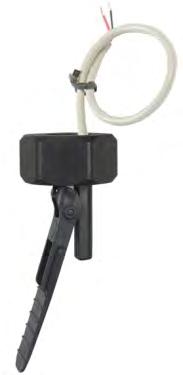
3 Summary Flow switches Summary 1-2 Flow switches historical and technical foreword 3 Technical information 4-8 R1B R1D R1R R1L (R1G) R1Y (R1E) R1S (R1F) R1P R1Q R1X R1V Paddle types, microswitch contact Plastic paddle, ¾ BSPP loose nut, fixed setting DN 15 DN 25 DN 25 Plastic paddle, ½ BSPP male thread, fixed setting, with built in Pt100 temperature sensor Plastic paddle, ½ BSPP male thread, fixed setting, with built in Pt100 temperature sensor Paddle types, reed switch contact Short plastic paddle, ½ BSPP male thread, gravity pull-back, fixed setting. DN 25 (Also exists with ½ NPT male thread = type R1G) DN63 DN 25 DN 20 PN3 DN20 DN 15 PN25 DN 15 Extended paddle arm, ½ BSPP male thread, gravity pull-back, fixed setting. (Also exists with ½ NPT male thread = type R1E) Long trimmable plastic paddle, ½ BSPP thread, magnetic spring, fixed setting. (Also exists with ½ NPT male thread = type R1F) Long trimmable plastic paddle, ¾ BSPP loose nut, magnetic spring, adjustable setting, slim design. Tee equipped with paddle flow switch, for spa applications, mounting on 1 (20 to 21mm ID) soft PVC tubes, adjustable setting. Long trimmable plastic paddle, ¾ BSPP loose nut, magnetic spring, adjustable setting. Long trimmable plastic paddle, ¾ BSPP loose nut, brass body, and brass nut, IP65 connection box, magnetic spring, adjustable setting


4 Summary R20 DN8 Flap type, in line mounting ½ BSPP male water inlet. Snap outlet for dia. 8 mm copper tube. For small size instant water heater. 27 R21 R23 R22 R3F R35 R34 R36 DN8 DN8 DN8 DN10 DN15 DN15 DN20 ½ BSPP male water inlet. Snap outlet for dia. 8 mm copper tube. For small size instant water heater. Built-in triac cooling plate. ½ BSPP water inlet. Outlet for dia. 8 mm copper tube. Built-in water pressure switch. For miniature Instant water heater. ½ BSPP water inlet. Outlet for dia. 8 mm copper tube. Built-in disc thermostat. For miniature Instant water heater with inlet temperature control. Piston type ½ BSPP male water inlet, Snap outlet for 10 mm dia. copper tubes. For instant water heater. Built-in over-pressure valve. ½ BSPP water inlet and outlet 34 Water inlet and outlet for copper pipes with O.D. 18 mm. 35 ¾ Water inlet and outlet, with built in 15 bar pressure valve. 36 Accessories 6R Fittings, saddles and other parts for paddle switch pipe mountings. 39 Lists and tables Flow switch selection table upon flow and diameter Alphabetical list and reference list 41 2

5 In antiquity, the flow measurement was one of the first means of time measurement. But it was not until the steam engines development and the need to control their water supply, that measuring devices were developed. The gas and potable water distribution network development, brought the city of Paris to mandate individual water meters in January These meters were operated by a piston system, whereas in England and Belgium, pioneer countries in this field, turbine systems were chosen. 1881, in the Paris first water meters, the measurement is performed by a piston (Jacquet s system) The development of electric and gas instant water heaters in the 1920/1930 brought the necessity of a security system to avoid heating when there is no flow. The use of paddles operating a switch had a major issue: avoid the leaks of the passage through the wall between the water circulating and the electrical switch. Gasket and were not efficient and wre reducing the flow measurement sensitivity, especially for small dimension appliances. The first flow switch using a piston, without connection passage between water and electrical section, appears to be the Walker type, where the metallic piston displacement is measured by two electromagnetic coils located outside the pipe Walker magnetic flow sensor for water heater: the metal piston (6) moves between two magnetic coils (3 and 4) US Patent In 1931, the first paddle switch with a magnetic action is invented by Louis E. Richmond (US Patent ). A paddle with a metallic roller actuates a balanced magnet with a mercury switch located outside. It was not until 1936 and the reed switch invention by the American engineer W. B. Ellwood of the Bell Telephone Laboratories (U.S. Patent 3,310,863) that freed paddle, piston or turbine flow sensors from gaskets and seals and allowed them to miniaturize. The reed switches are now used in thousands of different applications, and the annual world production is counted in hundreds of millions of pieces. 3


6 Operation Paddle and micro-switch types In the in line types, only a part of the flow, function of the ratio between the pipe section and the paddle surface actuates the flow switch 1: Cable 2: Body 3: Microswitch 4: Resin filling 5: ¾ Loose nut or ½ male thread 6: Fitting gasket 7: Paddle gasket 8: Paddle 1: Cable 2: Body 3: Microswitch 4: Resin filling 5: ¾ Loose nut or ½ male thread 6: Fitting gasket 7: Paddle gasket 8: Paddle In the paddle and switch flowswitches, the paddle is pushed by the water flow and actuates a microswitch. The seal between the paddle and the electric part is made by a Santoprene elastomeric gasket. Set point calibration value is given mainly by the paddle length and its the surface, the microswitch actuating force, the pipe diameter. As in all paddle flow switches, due to the weight of the paddle, the setting will vary slightly according to the mounting position (horizontal or vertical, and in the latter case, flow inlet direction from top to bottom or from bottom to top). During assembly it is important to check that the paddle is correctly oriented in the flow direction and that no friction or obstacle hinders its movement. Therefore it is better to focus on devices with ¾ union nut mounting, or clips and O-ring assembly (type Ultimheat Snap-in), which allow easy aorientation djustment, unlike models with fixed thread. The temperature and pressure withstanding values, as well as resistance to chemical products are limited by the paddle gasket material. These models have the advantage of high electrical rating, and do not contain magnets, allowing them for use with liquids that may contain magnetic particles. In the ½ fixed thread types, it is possible to include a built-in temperature sensor: NTC, thermocouple, or Pt100, thus allowing the liquid temperature measurement. 1: Paddle 2: Reed switch 3: Magnet Paddle and reed switch types, gravity back-force In the in line types, only a part of the flow, function of the ratio between the pipe section and the paddle surface actuates the flow switch 4: Body 5: Resin filling 6: Gasket (on models with cylindrical thread) 7: Cable 1: Paddle 2: Reed switch 3: Magnet 4: Body 5: Resin filling 6: Gasket (on models with cylindrical thread) 7: Cable In the gravity pull-back paddle flow switches, when the upstream flow pushes against the paddle, the paddle swings away. This changes the position of the magnet in relation to the reed contact and thus activates the contact. As soon as the flow decreases or is interrupted, the paddle moves back to its starting position, and reed switch comes back to its starting contact position. The force necessary to push the paddle is provided by the magnets repelling each other. Our fixed setting paddle switches use only two magnets, and our adjustable setting types have one extra magnet use for repelling force adjustment. This system has no communication or gasket between the paddle and the electrical part. No metal parts are in contact with the liquid, with the exception of some models with a titanium axis. Therefore they are particularly suitable for applications on aggressive liquids, swimming pool water, sea water, or chloration or bromisation equipment. Most models can be used on pipes from 20 to 100 mm diameter, by using an adapted length paddle. Set point calibration value is given mainly by the paddle length and surface, the diameter of the pipe, and, in adjustable versions by the position of the magnet position adjusting screw. As in all paddle flow switch range, due to the weight of the paddle,the setting will vary slightly according to the mounting position (horizontal or vertical, and in the latter case, flow inlet direction from top to bottom or from bottom to top) During assembly it is important to check that the paddle is correctly oriented in the flow direction and that no friction or obstacle hinders its movement. As the paddle is magnetic, the circuit must be free of all magnetic particles. The low electrical ratings of the reed switches limit their use in pilot circuits or electronic circuits. 4


7 Paddle and reed switch types, magnetic pull-force, slim design In the paddle types, only a part of the flow, function of the ratio between the pipe section and the paddle surface, actuates the flow switch 3 magnets, factory adjustable set point type, smallest external foot print 2 magnets fixed setting, the lowest foot print 1: Magnets 2: Reed switch 3: Cable 4: Resin filling 5: Body 6: Paddle 7: 3/4 BSPP plastic Nut 8: Adjustment screw 9: Fitting gasket 1: Magnets 2: Reed switch 3: Wires or cable 4: Resin filling 5: Body with 1/2 thread 6: Paddle 7: Fitting gasket In the paddle and reed switch types, with magnetic pull-force and slim design, the flow pushes against the paddle, the paddle swings away and the reed switch contact closes. As soon as the flow decrease or is interrupted, the paddle is pulled back by the magnet to its starting position, and reed switch contact opens. The fixed setting paddle switches with slim design use only two magnets, but the adjustable setting types have one extra magnet used for force adjustment. This system has no communication or gasket between the paddle and the electrical part. No metal parts are in contact with the liquid, with the exception of some models with a titanium axis. Therefore they are particularly suitable for applications on aggressive liquids, swimming pool water, sea water, or chloration or bromisation equipment. Most models can be used on pipes from 20 to 100 mm diameter, by using an adapted length paddle. Set point calibration value is given mainly by the paddle length and surface, the diameter of the pipe, and, in adjustable versions by the position of the adjusting screw. As in all paddle flow switch range, due to the weight of the paddle, the setting will vary slightly according to the mounting position (horizontal or vertical, and in the latter case, flow inlet direction from top to bottom or from bottom to top) During assembly it is important to check that the paddle is correctly oriented in the flow direction and that no friction or obstacle hinders its movement. Therefore it is better to focus on devices with ¾ union nut mounting, or clips and O-ring assembly (type Ultimheat Snap-in), which allow easy orientation adjustment, unlike models with fixed thread. As the paddle is magnetic, the circuit must be free of all magnetic particles. The low power ratings of the reed switches limit their use in pilot or electronic circuits Paddle and reed switch types, magnetic back-force, long design In the paddle types, only a part of the flow, function of the ratio between the pipe section and the paddle surface, actuates the flow switch 2 magnets fixed setting, external mechanism 2 magnets adjustable setting, external mechanism 1: Cable 2: Cover 3: Magney 4: Magnet 5: Body 6: Paddle 7: Titanium axis 8: 3/4 BSPP plastic loose nut 9: Fitting gasket 10: Reed switch 11: Resin filling 1: Connection box cover 2: Connector or cable gland 3: Adjustment screw and dial 4: Body cover 5: Magnet 6: Magnet 7: Body 8: Paddle 9: Titanium axis 10: 3/4 BSPP nickel plated brass Nut 11: Fitting gasket 12: Reed switch 13: Wires 14: Resin filling 15: Connection box frame 16: Connection block In the paddle and reed switch types, with magnetic pull-force and long design, the flow pushes against the paddle, the paddle swings away and the reed switch contact closes. As soon as the flow decreases or is interrupted, the paddle is pulled back by the magnet to its starting position, and reed switch contact opens. This system has no communication or gasket between the paddle and the electrical part. No metal parts are in contact with the liquid, with the exception of some models with a titanium axis. Therefore they are particularly suitable for applications on aggressive liquids, swimming pool water, sea water, or chloration or bromisation equipment. Most models can be used on pipes from 20 to 100 mm diameter, by using an adapted paddle length. Set point calibration value is given mainly by the paddle length and surface, the diameter of the pipe, and, in adjustable versions, by the position of the adjusting screw. As in all paddle flow switch range, due to the weight of the paddle,the setting will vary slightly according to the mounting position (horizontal or vertical, and in the latter case, flow inlet direction from top to bottom or from bottom to top) During assembly it is important to check that the paddle is correctly oriented in the flow direction and that no friction or obstacle hinders its movement. As the paddle is magnetic, the circuit must be free of all magnetic particles. The low power ratings of the reed switches limit their use in pilot or electronic circuits 5

.")

8 Hinged flap and reed switch type In the hinged flap types, 100% of the flow goes through the flow switch 1: Magnet 2: Reed switch 3: Wires or cable 4: Resin filling 5: Flap 6: Adjustment weight 7: Body 8: Auxiliary plate for triac or other components In In line flap reed flow switches, the hinged flap is moved by the water flow and closes a reed switch contact. There is no sealing problem between the liquid and electrical side, because both are completely separated. When the flow stops or decreases, the magnetic flap returns to its original position by its own weight (vertical position and bottom water inlet are required). The detection set point value is given by a variable mass lodged in the flap. This solution is suitable for small diameter pipes and wall mounting instant water heaters. As the flap is magnetized, the circuit must be free of all magnetic particles. These devices include a location for mounting an auxiliary system: water cooled triac heat exchanger, pressure switch, disc thermostat or temperature sensor. The low power ratings of the reed switches limit their use in pilot or electronic circuits. 1: Wires 2: Piston 3: Resin filling 4: Magnet 5: Reed switch 6: Spring 7: Clips 8: Body Piston and reed switch types Piston type flow switches place a piston directly in 100% of the flow path 9: Overpressure valve (Option) 1: Wires 2: Piston 3: Resin filling 4: Magnet 5: Reed switch 6: Spring 7: Clips 8: Body 9: Overpressure valve (Option) Inside in line piston and reed type flow switch, the piston, when displaced by the pressure differential from fluid flow, magnetically actuates a reed switch. There is no sealing problem between the liquid and electrical part because both are completely separated. When the flow stops or decreases, the magnetic piston comes back to its original position by its own weight (vertical installation, water inlet downside), or by a spring (vertical, water inlet upside). The detection set point value is given mainly by the piston shape, its mass and eventually by the spring pull back force. This solution is suitable for small diameter pipes. The piston being magnetized, the circuit must be free of all magnetic particles. The low power ratings of the reed switches limit their use in pilot or electronic circuits. 6
9 Description of the different parts The electrical contact system: reed switch or micro-switch. A certain force is required to actuate the electrical contact device. It can range from a few tenths of grams for systems with reed contacts with a power rating of 10 to 20VA (0.5Amp), to 50 grams for snap action micro-switches with a 5Amp 250V rating In general, the force required to operate an electrical contact increases with its electrical rating, and the power available on the detector depends on the paddle, piston or flap characteristics Most flow switches in this catalog use reed switches because they are used for detection level in low voltage and low current electronic circuits. This makes possible to design compact devices. Reed switches Reed switches are small glass bulbs with a flexible reed strip contact with a breaking capacity of 10 to 70VA, which has the particularity to close in the presence of a magnetic field. These glass bulbs are sealed and filled with argon or under vacuum, therefore they are protected from oxidation Reed switch applications in flow switches Suitable Not suitable Computer circuits Small electrical motors, including small DC motors Programmable logic controller (PLC s) circuits Power contactor coil circuits (Unless protected by an arc suppression circuit) Small relays Solenoid valves (Unless protected by an arc suppression circuit) Solid state relay (SSR) trigger circuits Incandescent lamps Reed switches contact protection Switching no load or loads where the voltage is less than 5 10 ma or less, the contacts undergo little or no wear and life times in excess of billions of operations are expected. In the 10 Volt range, higher contact wear will take place. Switching ma, life times of 50 million to 200 million operations can be expected. When switching inductive loads such as relays, solenoids and transformers, reed switch contacts require protection in order to insure long, dependable life. When current is interrupted, the inductance or electrical inertia of the load generates a large high frequency voltage, which appears across the switch contacts. If the voltage is large enough, it can break down the medium in the gap between them, making a conductive path. This phenomenon is called arcing. Arcing can cause the contacts to burn, weld together or stick.the purpose of protection circuits is to prevent arcing, by shorting this voltage through an alternate path DC load contact protection circuit with diode AC load contact protection circuit with R/C circuit A 1N4004 diode is connected cathode-to-positive.the diode does not conduct when the load is energized, but conducts and shorts out the peak transient generated voltage when the switch opens. A resistor can be added in series with the diode. DC load protection contact with Back to Back Zener diode The peak transient voltage that occurs when the switch opens is decreased to a value equal to the back to back Zener diode voltage. The Zener diode should be sized for a voltage somewhat higher than the circuit source voltage Piston types When magnet located inside the piston arrives at the center of the reed switch, the contact closes. Therefore, piston movement is limited to achieve requested operation mode. A resistor (R) and capacitor (C) are connected in parallel with the switch. The capacitor has high impedance at 50/ 60 hertz, and is essentially a short circuit to high frequencies of generated voltages. Capacitor value: C = I²/10 Resistor value (E= power supply voltage): R = E / (10.I (I+50 / E ) ) AC load protection contact with Varistor The varistor resistance decreases sharply when voltage reaches its trigger value, and shorts out the peak transient generated voltage when the switch opens. Varistor should be sized for a voltage somewhat higher than the circuit source voltage Magnet displacement and reed switch operation in flow switches Paddle and flap types A magnet is located inside the paddle or inside the flap. When it arrives near the reed switch, the contact closes. Snap action switches On snap action switches, contact opening speed is around 1m per second. The contact spacing reaches the distance to extinguish the arcing in less than 1/1000 sec. Therefore there is no radio interference, and the contact does not deteriorate. Mechanically, this type of contact, also called energy storing contact is much more complicated, expensive, and does not allow such a great control than reed switches. The snap action microswitch is particularly suitable for devices operating at 240 or 400 V and when high electrical rating is required Microswitches vs reed switches in flowswitches Disadvantages Advantages Microswitches are more expensive than reed switches Microswitches have higher electrical ratings, in 110VAC and 230VAC Microswitches have a higher operating force, so they need larger paddles Microswitches are easily made with SPNC, SPNO or change over contacts Micro-switches have large differential travels, providing large flow differentials between contact opening and close Snap action contact switches generate very low EMC 7
10 Magnets (In reed switch devices) Selecting a magnet for a flow switch application must take into account the characteristics of the liquid in which it will be immersed, of the temperature at which it will be subjected, of its corrosion resistance, of the magnetic field required to operate the switch and its distance to the reed switches. Ferrite magnets have a good resistance to corrosion, but a very low magnetic power. Neodymium -Iron-Boron magnets contain 60-75% iron (amount is dependent on grade) and are therefore prone to corrosion, but a very big magnetic power. So these magnets are nickel plated and plastic overmolded. Both these magnets have a good temperature resistance up to 100 C Electrical wiring For reed switch systems, the most common electrical connection is by wires or cable. Given the low electrical rating of reed switches, conductor cross section is generally less than or equal to 0.5 mm ². If there is no thermal stress or environmental conditions, wires and cables are PVC insulated. Silicone insulation, FEP and Teflon are not recommended because they do not provide hermetic sealing with resin filling and may let water or moisture inside the product. Tabs or connector outputs are recommended for large quantities. Resin filling (For reed switch types) The resin filling provides two functions - Mechanically securing the reed in the body, and provide its resistance to tearing (Standards impose a tearing resistance equal to or greater than 10N) - Main electrical insulation of the electrical contact and wiring. This requires a UL94-VO resin. In some customer applications the insulation class I is insufficient, and the contact system must receive and additional insulation to comply to the requirements of insulation class II Mechanical stop of measuring device The mechanical displacement of the piston or paddle must be limited to remain within the limits of the magnet position detection by the reed switch. Mechanism body and mounting system Choice of material: The body of the mechanism provides several functions: - Device protection against electric shock, water ingress, pressure value, and chemicals. Plastics used for the body are always UL94-VO rated - The use in potable water systems: Models intended for use in drinking water are made of plastic and metal parts in contact with water that meets the specifications of the WRC (Water Research Council) - The flow switch mounting: This mounting can be secured by NPT or BSPT (Tapered) threads, or BSPP cylindrical threads or metric threads. Tapered threads require sealing on the threads, and the cylindrical threads require sealing by a flat gasket or O-ring Ingress protection On flow switches using a magnetic mechanism, liquids containing magnetic particles such as iron filings must be avoided, because these particles will accumulate on the magnet. It is possible to use a magnetic trap upstream if it is not possible to avoid magnetic flow switches in the final application External environment protection This protection can have several functions: - Ingress protection against attacks from the outside environment (rain, dust, shock). Most of our flow switches have their electrical components potted inside an electrical insulation and waterproof resin. Some of them can also be provided with waterproof protection box - Protection against the conditions in which the product will be installed in its application. In most cases, level switches will be integrated by an OEM into a machine or equipment. Then it is this machine or equipment that will ensure protection against water, dust, shock and other contaminants. - Protection against gas and dust explosive atmospheres: flow switches were not initially designed for use in these environments and therefore may not meet the applicable standards in this field of application. Overmolded reed switches do not have potential sources of ignition. On special request, they can be subjected to an ignition hazard assessment according to DIN EN : They could be, therefore, not subject to directive 94/9/EC, and used as a simple electrical device for connection to a certified intrinsically safe circuit in accordance with DIN EN : Compliance with the European directive (Machinery directive): These flow switches are not a safety component as described in this directive. Their operational safety is only guaranteed when they are used for flow monitoring of liquids, inside the limits given by their data sheets and instruction manual. 1/2 3/4 Threads and threaded pipe connections G R NPT The correspondences between the threads, and they may have different names in different countries and often it is difficult to understand catalogs and plans. The threads used in flow sensors can be: - ½ NPT: tapered thread, American standard ANSI B ½ BSPT: tapered thread, meet ISO-7-1, DIN2999, BS21, often called conical gas thread or conical gas, but they may also be described in documents under the abbreviation Rp, R and in France conical (for ½ ), and conical (for the ¾ ) - ½ BSPP and ¾ BSPP: cylindrical thread, described in ISO 228, DIN259, often called cylindrical gas thread or BSP, as described on the documents under the abbreviation G, and in France cylindrical (for ½ ), and cylindrical (for the ¾ ). Male cylindrical threads are mounted in cylindrical female thread, with a flat gasket or an O-ring seal on a flat seal seat. The tapered male threads are mounted in cylindrical female threads with a sealant on the pitch. In tapered threads, there is a strong resemblance between BSPT and NPT in sizes ½ and ¾. For these dimensions only, they have the same pitch, diameters very close, and a slight pitch angle difference (55 and 60 ), and this explains why in some cases, and for plastic threads, ½ NPT male will fit quite correctly in a BSPP female thread. PN and temperature resistance The Nominal pressure (PN) is the pressure which is often used in the design of a pipeline. This value is expressed in bar, as the pressure at the temperature of 25 C for which the equipment is able to withstand pressure without failure and with adequate security during a given time. At 25 C the nominal pressure corresponds to the maximum operating pressure (PFA). This pressure varies with temperature and the characteristics of the material used, so great care must be taken when this concept is used. The main standard is EN for drinking water supply pipes in PVC. This standard provides the correction coefficient of the maximum operating pressure between 20 and 45 C for PVC. Maximum operating pressure correction on flow switches upon their body material Maximum operating pressure correction coefficient against temperature on PVC tubes (From EN ) 8


11 Other catalogues Distributor: info@ultimheat.com Web: NT3ENTSG06U2A MAJ
Introduction to the flow switches technology. J.Jumeau
 Introduction to the flow switches technology J.Jumeau 20121030 P 1/6 In antiquity, the flow measurement was one of the first means of time measurement. But it was not until the steam engines development
FLOW SWITCHES AND COMBINATION CONTROLS
 6 ULTIMHEAT FLOW SWITCHES AND COMBINATION CONTROLS The professional solution: an extended, rational, and consistent range of products Technical catalogue for R&D department Edition 28/05/2013 E-Mail :
FLOW SWITCHES AND COMBINATION CONTROLS
 6 ULTIMHEAT FLOW SWITCHES AND COMBINATION CONTROLS The professional solution: an extended, rational, and consistent range of products Technical catalogue for R&D department Edition 28/05/2013 E-Mail :
Introduction to the level switches technology. J.Jumeau
 Introduction to the level switches technology J.Jumeau 20121030 P 1/6 If the level measurement, especially for meteorological purposes seems to date back to the 4th or 5th century BC in India, the development
FLOAT LEVEL SWITCHES Vertical and horizontal models For OEM applications
 7 ULTIMHEAT FLOAT LEVEL SWITCHES Vertical and horizontal models For OEM applications The professional solution: an extended, rational, and consistent range of products Technical catalogue for R&D department
FLOAT LEVEL SWITCHES Vertical and horizontal models For OEM applications
 7 ULTIMHEAT FLOAT LEVEL SWITCHES Vertical and horizontal models For OEM applications The professional solution: an extended, rational, and consistent range of products Technical catalogue for R&D department
ULTIMHEAT PRESSURE SWITCHES
 5 ULTIMHEAT PRESSURE SWITCHES Air switches Positive Pressure switches Vacuum pressure switches Differential pressure switches Elastomer membrane types, medium pressure range (20 to 1500 mbar) The professional
ingress protection housings and connection boxes for heating elements
 2 ULTIMHEAT ThermostatS with ingress protection housings and connection boxes for heating elements The professional solution: an extended, rational and consistent range of products Technical catalogue
FLOW SWITCHES. With pipe tees (inline) Direct installation (insertion) For OEM applications Flow monitors. Including products with:
 Direct installation (insertion) For OEM applications Flow monitors. Including products with:") JJ With pipe tees (inline) JJ Direct installation (insertion) JJ For OEM applications JJ Flow monitors Including products with: UL 508 UL 353 CSA C22.2#14-10 FLOW SWITCHES DS_Flow_switches 05/2014 7 Reliable
JJ With pipe tees (inline) JJ Direct installation (insertion) JJ For OEM applications JJ Flow monitors Including products with: UL 508 UL 353 CSA C22.2#14-10 FLOW SWITCHES DS_Flow_switches 05/2014 7 Reliable
SIKA Flow Switches -1-
 SIKA Flow Switches -1- SIKA Flow Switches Reliable Safe Proven! Our tried-and-tested flow monitoring switches are used for two basic purposes: To ensure a minimum flow rate, e.g. of cooling water or lubricating
flow switches J with pipe tees (inline) J Direct installation (insertion) J for hvac applications J with interchangeable paddles J For air flow
 J Direct installation (insertion) J for hvac applications J with interchangeable paddles J For air flow") J with pipe tees (inline) J Direct installation (insertion) J for hvac applications J with interchangeable paddles J For air flow Including products with: UL 508 UL 353 CSA C22.2#14-10 flow switches J
J with pipe tees (inline) J Direct installation (insertion) J for hvac applications J with interchangeable paddles J For air flow Including products with: UL 508 UL 353 CSA C22.2#14-10 flow switches J
Reliable - Safe - Proven!
 SIKA Flow Switches SIKA Flow Switches Reliable - Safe - Proven! Our tried-and-tested flow monitoring switches are used for two basic purposes: To ensure a minimum flow rate, e.g. of cooling water or lubricating
CORROSION RESISTANT IN LINE FLOW SWITCHES
 ULTRASWITCH P20 SERIES CORROSION RESISTANT IN LINE FLOW SWITCHES Magnetically sprung piston provides exceptional reliability FEATURES SUITS TUBES & PIPES 6 TO 20 MM ( 1 /4 TO /4 ) DIA. NO METAL PARTS IN
B21 Series BASOTROL Gas Valve
 Installation Instructions B21 Issue Date September 19, 2017 Installation IMPORTANT: These instructions are intended as a guide for qualified personnel installing or servicing BASO Gas Products. Carefully
THE BEST ELECTRICAL CONTROLS BUSINESS ON THE PLANET! Unmatched Service Superior Product Quality Advantage Pricing
 Introduction A contactor is an electrical device which is used for switching an electrical circuit on or off. It is considered to be a special type of relay. However, the basic difference between the relay
TABLE OF CONTENTS. Push Button and Rocker Switches Pag. 4. Signal Lights and Lenses Pag. 14. Pressure Switches Pag. 24
 1 TABLE OF CONTENTS Push Button and Rocker Switches Pag. 4 Signal Lights and Lenses Pag. 14 Pressure Switches Pag. 24 2 Push button and Rocker Switches 3 Switches Push button SERIES L4 L4 Bowl L4 Rubber
LEVEL SWITCH WITH 1 FLOAT
 RIL210 LEVEL SWITCH WITH 1 FLOAT LEVEL Immersion level controller with 1 or 2 control points It can be used for dirty liquids, water, petroleum, cutting oils, and tolerates the presence of metal and ferrous
ENGLISH Datasheet Platinum Resistance Pt100 4 wire class B Resistance Thermometer with Compact KNS Head
 ENGLISH Datasheet Platinum Resistance Pt100 4 wire class B Resistance Thermometer with Compact KNS Head Pt100 probe with compact KNS terminal head Class B, 4 wire connection Various probe available lengths
Compact System NRGS 11-2 NRGS Original Installation Instructions English
 Compact System NRGS 11-2 NRGS 16-2 EN English Original Installation Instructions 810366-05 1 Contents Important Notes Page Usage for the intended purpose...4 Safety note...4 LV (Low Voltage) Directive
TECHNICAL GUIDE FOR PROXIMITY SENSORS DEFINITIONS YAMATAKE PROXIMITY SENSOR CATEGORIES
 TECHNICAL GUIDE FOR PROXIMITY SENSORS DEFINITIONS "" includes all sensors that detect the presence of a metallic object approaching the sensing face or near the sensing face without mechanical contact.
Power Supplies POWER SUPPLIES TRANSIENT VOLTAGE SUPPRESSORS POWER LINE FILTERS. AC to DC Power Supply Units. AC to 24VDC Regulated Primary Switching
 Power Supplies AC to DC Power Supply Units AC to 24VDC Regulated Primary Switching Single Phase 100 / 240 VAC 24VDC 5 VDC 12VDC 48VDC 1 Amp TO 20 Amp Three Phase 480 VAC 24VDC 10 Amp to 50 Amp DIN RAIL
37T Series Moisture Resistant Temperature Controls
 37T Series Moisture Resistant Temperature Controls Moisture Resistant Temperature Control The 37T series of 3/4 (19mm) bimetal disc temperature controls from Therm-O-Disc offers proven reliability in a
ABB ! CAUTION. Type KRV Directional Overcurrent Relay E 1.0 APPLICATION 2.0 CONSTRUCTION AND OPERATION. Instruction Leaflet
 ABB Instruction Leaflet 41-137.2E Effective: February 1994 Supersedes I.L. 41-137.2D, Dated February 1973 ( )Denotes Change Since Previous Issue. Type KRV Directional Before putting relays into service,
ANGLE SEAT AIR ACTUATED VALVES 2 Way (2/2)
") ANGLE SEAT AIR ACTUATED VALVES 2 Way (2/2) BRASS OR STAINLESS STEEL BODY POLYMER OR METAL ACTUATOR HERION USA Inc. Valve Technology and Systems Brochure N-285 Multi-Accessory Polymer Head versions Increased
ANGLE SEAT AIR ACTUATED VALVES 2 Way (2/2) BRASS OR STAINLESS STEEL BODY POLYMER OR METAL ACTUATOR HERION USA Inc. Valve Technology and Systems Brochure N-285 Multi-Accessory Polymer Head versions Increased
KOBOLD VKA FLOWMETER/SWITCH. User Instructions. Manual-VKA_03-04
 KOBOLD VKA FLOWMETER/SWITCH User Instructions Manual-VKA_03-04 VKA Table of Contents 1.0 General............................................. 1 Specifications..........................................
With pipe tees (inline) Direct installation (insertion) With interchangeable paddles For air flow. flow switches
 Direct installation (insertion) With interchangeable paddles For air flow. flow switches") JJ With pipe tees (inline) JJ Direct installation (insertion) JJ For HVAC applications JJ With interchangeable paddles JJ For air flow flow switches DS_Flow_switches 06/2016 7 Flow switches SIKA has over
JJ With pipe tees (inline) JJ Direct installation (insertion) JJ For HVAC applications JJ With interchangeable paddles JJ For air flow flow switches DS_Flow_switches 06/2016 7 Flow switches SIKA has over
Power Supplies. POWER SUPPLIES AC to 24VDC Regulated Primary Switching. TRANSIENT VOLTAGE SUPPRESSORS Industrial Design MINI UNIVERSAL MOUNT
 Power Supplies AC to DC AC to 24VDC Regulated Primary Switching SINGLE PHASE 115 / 230 VAC 24VDC 5 VDC 12VDC 10 AMP TO 20 AMP THREE PHASE 480 VAC 24VDC 10 AMP TO 50 AMP! DIN RAIL MOUNT! COMPACT DESIGN
Transmitters: Relay Valve VR4151/4152
 Relay Valve VR4151/4152 Appropriate output sequences are affected according to the signal received from the mechanical valve. VR4151 VR4152 Precautions Be sure to read before handling. Refer to pages 5-11-2
S840, S845, S846 Series Single-break changeover, NC or NO contacts, positive opening operation and wiping action Catalogue D40.en
 Snap-action switches S80, S85, S86 Series Single-break changeover, NC or NO contacts, positive opening operation and wiping action Catalogue D0.en Snap-action switches, S80, S85, S86 Series Single-break
METAL DETECTOR AND REJECTION SYSTEM FOR PIPELINE APPLICATIONS
 DEVICE DESCRIPTION This metal detector and rejection system was specially developed to meet high detection and hygiene requirements in the analysis of liquid and viscous products (sauces, jams, marmalades,
Hermetically Sealed Power Contact
 Hermetically Sealed Power Contact What is Bestact? Sealed switches in glass tube with inert gas Q: What is Bestact? A : Briefly, it is a hermetically sealed contact in a glass tube that can be used in
CATALOG. Actuated Diaphragm Valve DN PVC-U / PVC-C / PP-H / PVDF / ABS SMART IN FLOW CONTROL.
 CATALOG Actuated Diaphragm Valve DN 15-100 PVC-U / PVC-C / PP-H / PVDF / ABS SMART IN FLOW CONTROL. TABLE OF CONTENTS Type 186 - DN 12-15 (MA 10) 04 General information - Technical specification 04 Sectional
Miniature Liquid Level Sensors
 C US File No. 1636 (L90200-27) Applications Typical applications include automatic vending machines, photocopiers, small collection tanks, miniature pumping stations, pilot plants and similar small system
General Information... Temperature/Resistance Table... Part Numbering Examples for RTD s. High Temperature MgO Elements (RA)...
...") Page General Information... Temperature/Resistance Table... Part Numbering Examples for RTD s High Temperature MgO Elements (RA).... Leadwire Style RTD s (RB).. Leadwire Style RTD s (RD, RE, RF, or RG
Page General Information... Temperature/Resistance Table... Part Numbering Examples for RTD s High Temperature MgO Elements (RA).... Leadwire Style RTD s (RB).. Leadwire Style RTD s (RD, RE, RF, or RG
SIKA Flow Switches -1-
 SIKA Flow Switches -1- SIKA Flow Switches Reliable Safe Proven! Our tried-and-tested flow monitoring switches are used for two basic purposes: To ensure a minimum flow rate, e.g. of cooling water or lubricating
BGD278 Series BASOTROL CE Approved Gas Valve
 Product Bulletin Issue Date November 16, 2012 BGD278 Series BASOTROL CE Approved Gas Valve The BGD278 Series gas valve is a combination main and pilot valve intended for use in conjunction with solid-state
PNEUMATICALLY ACTUATED 2-WAY
 482 DN 25-65 The 482 diaphragm valve is particularly suitable for shutting off and regulating abrasive or dirty fluids. The new internal geometry of the body optimises fluid dynamic efficiency by increasing
Series S847 Changeover switches featuring wiping, galvanically isolated, double-break contacts and positive opening operation Catalogue D47.
 Snap-action switches Changeover switches featuring wiping, galvanically isolated, double-break contacts and positive opening operation Catalogue D47.en Snap-action switches, S847 Series Dual changeover
CIRCLE SEAL CONTROLS
 CIRCLE SEAL CONTROLS ATKOMATIC SOLENOID VALVES INSTALLATION, MAINTENANCE, AND OPERATION INSTRUCTIONS 13000 SERIES Stainless, Normally Closed, Direct Lift, 3-Way Valve Installation Instructions WARNING:
FL7M-A Series. Aluminum-chip Immunity DC 2-wire Type Cylindrical Proximity Sensors. Specifications. click FEATURES ORDER GUIDE
 6 FL7M-A Series FEATURES Workpieces Reliably Sensed Even if Aluminum or Cast Iron Chips Accumulate on the Sensing Head. This DC 2-wire type proximity sensor can be directly connected to programmable controllers
Function Fittings. Flow Control Regulators. Piloted Function Fittings. Non-Return Valves. LIQUIfit Pressure Fittings. Other Function Fittings
 Flow Control Regulators Piloted Non-Return Valves LIQUIfit Pressure Fittings Other Silencers Flow Control Regulators (P. 4-6) Blocking Fittings (P. 4-36) Piloted Non-Return Valves (P. 4-38) Function:
STAINLESS STEEL ARES PNEUMATIC ANGLE-SEAT VALVE
 FEATURES The stainless steel ARES valve is intended for the automatic shut-off of networks of fluids. The full-bore, inclined-seat body and the excellent flow-rate coefficients allow for very low pressure
INLINE Flow sensor for hazardous area II 1 G/D - II 2 D - II 3 GD - I M1
 INLINE Flow sensor for hazardous area II G/D - II D - II GD - I M Type SE0 Ex can be combined with... Flow meter with NAMUR or NPN/PNP output signal Mounting, dismounting of electronics by a Quarter-Turn
SECTION Pressure & Temperature Control
 16 Pressure & Temperature Control ARMSTRONG PRODUCT CATALOGUE 70 Pressure Reducing s Pressure Reducing s Armstrong pressure reducing valves (PRVs) and temperature regulators help you manage steam, air
BRONZE ZEUS PNEUMATIC ANGLE-SEAT VALVE
 FEATURES The bronze ZEUS valve is intended for the automatic shutoff of networks of fluids. The full-bore inclined-seat body and the excellent flow-rate coefficients allow for very low pressure drops.
INTEGRATED HYDRAULIC BRAKE ACTUATORS
 INTEGRATED HYDRAULIC BRAKE INTEGRATED HYDRAULIC BRAKE INTEGRATED HYDRAULIC BRAKE The integrated hydraulic brake is comprised of a pneumatic cylinder that acts as an actuator and an oleo-dynamic circuit
CERAMIC CONNECTION BLOCKS and Special connectors
 10 ULTIMHEAT CERAMIC CONNECTION BLOCKS and Special connectors The professional solution: an extended, rational, and consistent range of products Technical catalogue for R&D department Edition 20/02/2013
Paddle-wheel flow controller for On/Off control
 Paddle-wheel flow controller for On/Off control Type 8032 can be combined with... Indication, monitoring, transmitting and On/Off control in one device Programmable outputs (transistor or relay) Automatic-calibration:
Coil Data Nominal Current MA Nominal VA Sealed Single Pole Normally Open (SPNO) White Rodgers Q
 White Rodgers Q") 14/03/08 A136 Relay - General Purpose 90-293Q Enclosed fan relays used for switching single or two speed fan motors, solenoids, relays, resistive loads, heating and cooling applications and general purpose
14/03/08 A136 Relay - General Purpose 90-293Q Enclosed fan relays used for switching single or two speed fan motors, solenoids, relays, resistive loads, heating and cooling applications and general purpose
The Discussion of this exercise covers the following points:
 Exercise 2 Float Switch EXERCISE OBJECTIVE Learn the working principle of float switches and how to use the float switch, Model 46935. DISCUSSION OUTLINE The Discussion of this exercise covers the following
Coil Data Nominal Current MA Nominal VA Sealed. Coil Data Nominal Current MA Nominal VA Sealed. Single Pole Double Throw (SPDT)
") 14/03/08 A136 Relay - General Purpose 90-293Q Enclosed fan relays used for switching single or two speed fan motors, solenoids, relays, resistive loads, heating and cooling applications and general purpose
14/03/08 A136 Relay - General Purpose 90-293Q Enclosed fan relays used for switching single or two speed fan motors, solenoids, relays, resistive loads, heating and cooling applications and general purpose
Magnetic-inductive flow meter EPS / UMF2. Technical data sheet
 Magnetic-inductive flow meter EPS / UMF2 Technical data sheet high accuracy: 0.3 % of actual maintenance-free no pressure drop numerous lining materials numerous electrode materials low-cost grounding
Model L-5 & L-5SS LIQUID LEVEL SWITCH. Specific Gravity Compensating
 LIQUID LEVEL SWITCH Specific Gravity Compensating Featuring continuously adjustable float buoyancy control to allow use in fluids with specific gravity down to 0.6 Continuous buoyancy control allows switch
Flow switches for insertion installation
 Flow switches for insertion installation Threaded adapter with trimmable paddle Type VHS06 Type VK306 Technical data VHS06 VK306 Switching function Contact closes at increasing flow opens at decreasing
Spiratec ST14, ST16 and ST17 Sensor Chambers and Sensors
 Local regulations may restrict the use of this product to below the conditions quoted. In the interests of development and improvement of the product, we reserve the right to change the specification without
485 - NC NO/DA DN
 485 - NC 285 - NO/DA DN 25-100 The 485/285 diaphragm valve is particularly suitable for shutting off and regulating abrasive or dirty fluids. The new internal geometry of the body optimises fluid dynamic
The full WeatherTRAK Flow3 Installation and Maintenance Manual is available online at
 Installation Manual INTRODUCTION The full WeatherTRAK Flow Installation and Maintenance Manual is available online at www.weathertrak.com General Description A WeatherTRAK Flow combines a hydraulic master
RSS Series Panel Mount Solid State Relays. 4,000 RMS (minute)
") RSS Series Panel Mount Solid State Relays Key features of the RSS series include: Photo isolation 1,200 volt blocking voltage 4,000 volt optical isolation Zero voltage turn-on 100% tested at rated current
RSS Series Panel Mount Solid State Relays Key features of the RSS series include: Photo isolation 1,200 volt blocking voltage 4,000 volt optical isolation Zero voltage turn-on 100% tested at rated current
AF series contactors (9 2650)
") R E32527 R E39322 contactors General purpose and motor applications AF series contactors (9 2650) 3- & 4-pole contactors General purpose up to 2700 A Motor applications up to 50 hp, 900 kw NEMA Sizes 00
R E32527 R E39322 contactors General purpose and motor applications AF series contactors (9 2650) 3- & 4-pole contactors General purpose up to 2700 A Motor applications up to 50 hp, 900 kw NEMA Sizes 00
Insertion magnetic inductive flowmeter
 Insertion magnetic inductive flowmeter Sensor without moving parts Flowmeter with On/Off control Application related calibration by Teach-In function Clean in place (CIP) FDA-compliant materials Type 8041
MS Application. Features. Proportional Valve Actuator General Instructions
 Proportional Valve Actuator Application The Proportional Valve Actuator is a non-spring return actuator used with proportional to 10 Vdc or 4 to 0 ma controllers and standard 1/" to 1-1/4" two-way and
EX Series. Electric Actuators for Ball and Butterfly Valves
 EX Series Electric Actuators for Ball and Butterfly Valves Next-Generation Electric Actuator Realization of Upgraded General-Purpose Actuators The modularization and adoption of the common parts have brought
Parts Manual. Transfer Switch. OTPCC (Spec A) 300/400/600 Amps. English Original Instructions (Issue 4)
 300/400/600 Amps. English Original Instructions (Issue 4)") Parts Manual Transfer Switch 00/00/600 Amps OTPCC (Spec A) English Original Instructions -20 962 0229 (Issue ) This catalog covers models produced under the Cummins /Onan and Cummins Power Generation brand
Parts Manual Transfer Switch 00/00/600 Amps OTPCC (Spec A) English Original Instructions -20 962 0229 (Issue ) This catalog covers models produced under the Cummins /Onan and Cummins Power Generation brand
SOLENOID VALVES FOR REFRIGERATING SYSTEMS
 SOLENOID VALVES 17 SOLENOID VALVES FOR REFRIGERATING SYSTEMS APPLICATIONS The solenoid valves, shown in this chapter, are classified Pressure accessories in the sense of the Pressure Equipment Directive
CIRCLE SEAL CONTROLS
 CIRCLE SEAL CONTROLS ATKOMATIC SOLENOID VALVES INSTALLATION, MAINTENANCE, AND OPERATION INSTRUCTIONS 3000 SERIES Bronze, Normally Closed, Direct Lift Installation Instructions WARNING: These instructions
Description. Positive safety relays
 Type N & KC Positive safety Description A.C. or D.C. operated DIN rail or panel mounting 600 volt heavy duty design, A600-10 amp, Q300-5 amp Snap-on accessories available: 1 & 4 pole adder deck Pneumatic
EZ-View Flow Meters. With Flow-Alert TM Flow Switch REDUCE MAINTENANCE COSTS TEL
 With Flow-Alert TM Flow Switch Reed switch and latching models Automatically signals alarm if flow is too high or too low Models available for AC or DC power supply Latching models include Hirschmann type
Series 581 ISO Pneumatic Directional Control Valves
 Series 581 ISO 5599-1 Pneumatic Directional Control Valves Series 581 Pneumatic Valves 01_1 st Headline_36 pt/14.4 mm 4-Way ISO Directional Control second line Series 581 - A complete series of standardized
MECHATRONICS LAB MANUAL
 MECHATRONICS LAB MANUAL T.E.(Mechanical) Sem-VI Department of Mechanical Engineering SIESGST, Nerul, Navi Mumbai LIST OF EXPERIMENTS Expt. No. Title Page No. 1. Study of basic principles of sensing and
EUROTHERM ONTROLS. Two phase thyristor power switches. Product data
 TC2000 TC2001 EUROTHERM ONTROLS Two phase thyristor power switches Product data TC2000 TC2001 Thyristor power switches Compact, two phase thyristor power switches for electrical heating applications from
DG 060 DG 061 DG 062 DG 063 DG 064 for Pressure and High Pressure Filters Operating pressure up to 600 bar Response/switching pressure up to 5,0 bar
 Clogging Indicators DG 060 DG 061 DG 062 DG 063 DG 064 for Pressure and High Pressure Filters Operating pressure up to 600 bar Response/switching pressure up to 5,0 bar Description Application Monitoring
Rosemount 8750WA Magnetic Flowmeter System For Water and Wastewater Industries
 Product Data Sheet January 214 813-1-475, Rev FA Rosemount 875WA Magnetic Flowmeter System For Water and Wastewater Industries THE 875WA MAGNETIC FLOWMETER Rosemount reliability in a customized offering
2-port and 3-port terminal unit valves PN16
 4 847 2-port valves VVP47..(S) 3-port valves VXP47.. cvatix 2-port and 3-port terminal unit valves PN16 3-port valves with bypass VMP47..(S) VVP47..(S) VXP47.. VMP47..(S) ronze valve body CC491K (Rg5)
Electrical panels TECHNICAL INFORMATION 104 ELECTRICAL PANELS 105 PROTECTION OF ELECTRICAL COMPONENTS 107 ELECTRICAL PANEL ACCESSORIES 110
 04 ELECTRICAL PANELS Electrical panels TECHNICAL INFORMATION 104 ELECTRICAL PANELS 105 PROTECTION OF ELECTRICAL COMPONENTS 107 ELECTRICAL PANEL ACCESSORIES 110 103 TECHNICAL INFORMATION Technical information
M-50/55 Series. Fixed setting flow switch with in-line flow
 M-50/55 Series Fixed setting flow switch with in-line flow Features Very accurate custom flow settings For corrosive and non-corrosive liquids or gases All-Teflon switch available Senses increasing or
CATALOG OF REPLACEMENT PARTS
 CATALOG OF REPLACEMENT PARTS MINI RACK OVEN OV310G ML-132515 A product of BAXTER MFG. CO., INC. 19220 STATE ROUTE 162 EAST, ORTING, WA 98360 FORM 43242 (October 2011) Table of Contents 3 ADVANCED CONTROL
RS/M SERIES. Modulating Gas Burners FIRING RATES
 The RS/M burners series covers a firing range from 45 to 2650 kw, and it has been designed for use in low or medium temperature hot water boilers, hot air or steam boilers, diathermic oil boilers. Operation
SL (AZ3) Micro Limit Switches
 Micro Limit Switches") SUBMINIATURE SIZE LIMIT SWITCHES SL (AZ3) Micro Limit Switches Quickly upgraded to limit switches with lamps by mounting an LED lamp socket. Rubber cover type (roller ) Compliance with RoHS Directive FEATURES
SUBMINIATURE SIZE LIMIT SWITCHES SL (AZ3) Micro Limit Switches Quickly upgraded to limit switches with lamps by mounting an LED lamp socket. Rubber cover type (roller ) Compliance with RoHS Directive FEATURES
MAHALAKSHMI ENGINEERING COLLEGE TIRUCHIRAPALLI
 MAHALAKSHMI ENGINEERING COLLEGE TIRUCHIRAPALLI 621213 QUESTION BANK --------------------------------------------------------------------------------------------------------------- Sub. Code : EE2402 Semester
VL (AZ8) Mini Limit Switches
 Mini Limit Switches") COMPACT SIZE LIMIT SWITCHES VL (AZ8) Mini Limit Switches A compact and accurate vertical limit switch. Type with a lamp which makes maintenance convenient; either a neon AC powered lamp or an LED DC powered
COMPACT SIZE LIMIT SWITCHES VL (AZ8) Mini Limit Switches A compact and accurate vertical limit switch. Type with a lamp which makes maintenance convenient; either a neon AC powered lamp or an LED DC powered
MERCURY CONTACTORS & RELAYS
 MERCURY CONTACTORS & RELAYS PHONE: 704-399-4248 FAX: 704-399-4167 WWW.SETHERMAL.COM INDEX GLOSSARYOFTERMS&EXPRESSIONS...1 GENERALINFORMATIONFEATURES&SELECTIONFACTORS...13 MERCURY TO METAL CONTACTORS AND
3TM Vacuum Contactors
 Catalog Extract HG 11.23 Edition 2016 Catalog Extract Medium-Voltage Equipment siemens.com/3tm R-HG11-343.psd 2 Siemens HG 11.23 2016 Contents Medium-Voltage Equipment Catalog Extract HG 11.23 2016 Contents
ULTIMHEAT INDUSTRIAL ELECTRONIC AND THERMOSTAT CONTROLS. The professional solution: an extended, rational, and consistent range of products
 3 ULTIMHEAT INDUSTRIAL ELECTRONIC AND THERMOSTAT CONTROLS electronic controllers, thermostatic control boxes, sub-assemblies and accessories for temperature control in electro-thermal equipment Y6-Y7-Y8
Programmable Logic Controller. Mat Nor Mohamad
 Programmable Logic Controller Mat Nor Mohamad Relays Electromagnetic Control Relays The PLC's original purpose was the replacement of electromagnetic relays with a solid-state switching system that could
l Snap-Action Switches
 Connect - Contact - Control 2 Brochure l Snap-Action Switches Snap-action switches I Page 2 Page 3 I Snap-action switches Double Safety A sky diver's life depends on his equipment. In case of emergency
Metal tube flowmeters Series M21 Variable area flowmeter for low flows of liquids, gases and steam
 Metal tube flowmeters Series M21 Variable area flowmeter for low flows of liquids, gases and steam Metallic tube with a robust construction Indication by means of magnetic coupling Scales calibrated in
flow x3 flow monitoring
 flow x3 flow monitoring The FlowX3 System includes a complete range of paddle wheel flow sensors, instruments and sensor installation fittings. Also included are insertion type electromagnetic flow transmitters.
Explosion-proof Solenoids ATEX. II 2 G / II 2 D EEx dm IIC T4, T5, T6. Catalogue 8735/GB. Maximum photo
 Explosion-proof Solenoids II 2 G / II 2 D EEx dm IIC T4, T5, T6 Catalogue Maximum photo ATEX Explosionproof solenoids with flameproof enclosure/encapsulation "dm" According to ATEX directive 94/9/EC and
1 Pneumatics. Transmitters VR4151 VR4152 VR1210 VR1220 VR1210F VR1220F VR1211F VR VR3200 VR3201 VR3100 VR3110
 Best 1 Pneumatics Transmitters Relay valve P. 1900 Side piping: 30 x 53 x 91 Bottom piping: 30 x 8 x 91 VR151 VR152 Effective area (mm 2 ) Number of ports Function 7 5 Metal Spool Shuttle valve P. 1902
Contactors. CH1130/02 Series Single pole high-voltage contactor up to 3 kv Catalogue C170.en. Connect - Contact - Control
 Connect - Contact - Control 3 Contactors CH1130/02 Series Single pole high-voltage contactor up to 3 kv Catalogue C170.en More information at: schaltbau-gmbh.com 42 CH1130/02 Single pole high-voltage contactor
( )
") (1-800-492-8826) OVERVIEW Convenient and ready-to-connect, WATTCO control panels include temperature, power, multi-loop, process, and safety limit controllers. Designed for electric heaters, control panels
(1-800-492-8826) OVERVIEW Convenient and ready-to-connect, WATTCO control panels include temperature, power, multi-loop, process, and safety limit controllers. Designed for electric heaters, control panels
(770)
") (770) 345-0010 OVERVIEW Convenient and ready-to-connect, WATTCO control panels include temperature, power, multi-loop, process, and safety limit controllers. Designed for electric heaters, control panels
(770) 345-0010 OVERVIEW Convenient and ready-to-connect, WATTCO control panels include temperature, power, multi-loop, process, and safety limit controllers. Designed for electric heaters, control panels
SECTION 4 ELECTRIC MOTORS UNIT 17: TYPES OF ELECTRIC MOTORS UNIT OBJECTIVES UNIT OBJECTIVES 3/21/2012
 SECTION 4 ELECTRIC MOTORS UNIT 17: TYPES OF ELECTRIC MOTORS UNIT OBJECTIVES After studying this unit, the reader should be able to Describe the different types of open single-phase motors used to drive
Clogging Indicators. Description. Page 393. Application Monitoring the contamination of pressure and high pressure filters.
 Clogging Indicators DG 023 DG 024 DG 041 DG 042 for Pressure and High Pressure Filters Operating pressure up to 450 bar / 5627 psi Response / switching pressure up to 5.0 bar / 73 psi Description pplication
Magnetic float switch For vertical installation Model FLS (models with Ex approval: 60, AL-ADF)
") Level measurement Magnetic float switch For vertical installation Model FLS (models with Ex approval: 60, AL-ADF) TC Fluid Control WIKA data sheet LM LM 3001 30.01 for further approvals see page 3 Applications
Level measurement Magnetic float switch For vertical installation Model FLS (models with Ex approval: 60, AL-ADF) TC Fluid Control WIKA data sheet LM LM 3001 30.01 for further approvals see page 3 Applications
Product. Information. A.u.K. Müller. Flow meter turbine, with shut-off device. Series Characteristics. Applications.
 Series 7.007 Solenoid valves Control valves Special valves and systems A. u. K. Müller GmbH & Co. KG Dresdener Str. 6 D-40595 Düsseldorf/Germany Tel.: +49(0)-79-0 Fax: +49(0)-79-8 e-mail: info@akmueller.de
VMH. www. delta-elektrogas.com. Safety shut off valves for gas with hydraulic actuator DN65 DN200 EE
 VMH Safety shut off valves for gas with hydraulic actuator DN65 DN200 www. delta-elektrogas.com EE168-0513 VMH Contents Description.. 3 Features.. 3 Functioning and application. 4 Special versions and
METAL DETECTOR AND REJECTION SYSTEM FOR MEAT EMULSION
 DEVICE DESCRIPTION This metal detector and rejection system has been specially developed for the high detection and hygiene requirements needed in the examination of meat emulsion. Versions are available
HIGH POWER SOLENOID DRIVER 1
 Elactis SA Switzerland Phone : Fax : E-mail : Web : +41 22 364 65 85 +41 22 364 65 87 info@elactis.com http://www.elactis.com HIGH POWER SOLENOID DRIVER 1 ADRV1012K 1 This datasheet is a preliminary description.
S826, S926 Series Dual changeover switches with positive opening operation and wiping contacts Catalogue D26.en
 2 Snap-action switches S826, S26 Series Dual changeover switches with positive opening operation and wiping contacts Catalogue D26.en 2 Snap-action switches S826 Series Dual changeover switches with positive