BIODEX SURGICAL C-ARM TABLES SERVICE MANUAL and and
|
|
|
- Eugenia Colleen Riley
- 5 years ago
- Views:
Transcription
1 SURGICAL C-ARM TABLES SERVICE MANUAL and and FN: Rev A 6/16 BIODEX Biodex Medical Systems, Inc. 20 Ramsey Road, Shirley, New York, , Tel: (Int l ), Fax: , info@biodex.com,
2 Surgical C-Arm Tables and and This manual covers installation and operation procedures for the following products: Urology C-Arm Table, 120 VAC Urology C-Arm Table, 230 VAC Brachytherapy C-Arm Table, 115 VAC Brachytherapy C-Arm Table, 230 VAC Contact Information Biodex Medical Systems, Inc. 20 Ramsey Road, Shirley, New York, Tel: (Int l ) Fax: supportservices@biodex.com 2
3 Table Of Contents Biodex Medical Imaging Table Warranty Control Module Replacement X Movement Actuator Replacement (Head-To-Toe) Y Movement Actuator Replacement (Lateral) Lift Actuator Replacement Lateral Tilt Actuator Replacement Head-To-Toe Tilt Actuator Replacement Tabletop Replacement Controller Box Replaceable Component Procedure Tilt Sensor Board Removal And Replacement Position Sensing Strip Replacement Procedure Table Calibration Procedure Caster Replacement Table Firmware Update Part And Assembly Illustrations
4 Biodex Medical Imaging Table Warranty 1. Product Warranty A. This equipment and its accessories (excluding cushions), are warranted by BIODEX MEDICAL SYSTEMS, INC. against defects in materials and workmanship for a period of two years from the date of shipment from BIODEX MEDICAL SYSTEMS, INC. During the warranty period, BIODEX MEDICAL SYSTEMS, INC. will in its sole discretion, repair (on-site), send replacement parts or replace the equipment found to have such defects, at no charge to the customer. EXCEPT AS STATED ABOVE, THERE ARE NO WARRANTIES, EXPRESSED OR IMPLIED, INCLUDING WITHOUT LIMITATION WARRANTIES OR MERCHANTABILITY OR FITNESS FOR USE. BIODEX DOES NOT ASSUME LIABILITY FOR INCIDENTAL, CONSEQUENTIAL OR INDIRECT DAMAGES INCLUDING LOSS OF USE, SALES, PROFITS OR BUSINESS INTERRUPTION. B. This warranty does not apply if the product, as determined by BIODEX MEDICAL SYSTEMS, INC., is defective due to abuse, misuse, modification or service performed by other than a BIODEX MEDICAL SYSTEMS, INC. authorized repair representative. Misuse and abuse include, but are not limited to, subjecting limits and allowing the equipment to become contaminated by fluid materials. C. In order to obtain warranty repair service and to expedite repair process, please contact BIODEX MEDICAL SYSTEMS, INC. Support Services Dept. at , and select product support as prompted. 2. Warranty Is Non-Transferable. 3. Non-Warranty Service A. Repairs and/or replacements not covered by this warranty may be performed by BIODEX MEDICAL SYSTEMS, INC. authorized service representatives. B. The cost of transportation to and from the service location will be the responsibility of the customer. 4
5 Service Procedure If you think you have a service problem, take the following action: 1. Check to see that the problem occurs more than once. 2. Refer to the instruction manual and operations procedure. If you still think you have a service problem, call BIODEX MEDICAL SYSTEMS, INC., Service Department at (800) and select product service as prompted. Keep yourself and the phone next to the equipment. 1. Service will ask you for a brief description of the problem. We will ask specific questions about the malfunction that occurred. This diagnostic process may take a few minutes, so call us when you can set aside an uninterrupted block of time. 2. After taking the information, we will advise on the action we will take. 3. Sometimes service personnel must consult with engineering and it may take time to get back to you. Be sure to let the service representative know your schedule so that we can call at a convenient time. 4. The return call may be from a person other than whom you first reported the problem to. 5. After analyzing the problem, we will decide if the unit can be repaired on site, or replacement parts will be sent. 6. If the unit must be returned, Biodex will provide a return materials authorization number (R.M.A. #.) Pack the table in the carton that it was originally shipped in. It is the customer's responsibility for any damage that occurs during shipping. 7. Non-warranty/non-service contract charges for repair are as follows: a. Materials + b. Time + c. Travel Zone Contact Information Biodex Medical Systems, Inc. 20 Ramsey Road, Shirley, New York, Tel: (Int l ) Fax: supportservices@biodex.com 5

6 1. CONTROL MODULE REPLACEMENT Tools Required: Phillips screwdriver The control module is located on the lower back panel. 1. To access the control module, remove the four larger Phillips screws securing the lower portion of the bellows to the clamshell covers. Each side has two screws located near the center of the clamshell. 2. The bellows is still secured to the top of the clamshell covers, but now it can be lifted and secured with bungee cords (see Figure 1.1). The table must be raised to its highest position to allow clearance to access and remove the controller. NOTE: If the table cannot be raised to the up position the covers must be removed. First remove the remaining 12 Phillips screws securing the lower portion of the bellows to the covers. Next, separate the covers by removing the four securing screws located at each end, and then slide the covers out. 3. Remove the six screws that secure the lower back panel (see Figure 1.2). Remove the lower back panel. Slide the control module out carefully. Make sure that the connecting cables are not being damaged as you slide the box out. 4. Disconnect all cables (see Figure 1.3). 5. Remove the six nuts that secure the module to the back panel. Figure

7 Six Phillips screws securing side cover/control box Figure 1.2. The Control box is secured with six nuts Calibration port LCD display cable X, Y, tilt position sense Hand/Foot control cable Main power coiled cable for X and Y,roll actuator Trendelenburg actuator Figure 1.3. AC pwr/battery Vertical actuator 7
8 2. X MOVEMENT ACTUATOR REPLACEMENT, (HEAD-TO-TOE) Tools Required: Allen keys Wire cutters Socket set, standard Phillips screwdriver REMOVAL 1. Make sure the table is level before you remove the actuator assembly. The table may abruptly move when the actuator is disconnected. 2. Remove the tabletop, which is secured with eight bolts (see Chapter 9, Tabletop Replacement). 3. Remove the tie wrap that holds the excess power cable of the actuator to the bed frame, and disconnect the actuator connector. 4. Remove the 7/16 bolts that secure the worm gear collar bracket to the frame. 5. Remove the two Allen screws holding the actuator-mounting clevis bracket to the frame. 6. Remove the clevis bracket from the actuator. 7. Cut the tie wraps holding the sound insulation on the actuator and carefully remove the insulation. The insulation will be re-used on the new motor. INSTALLATION Note: A calibration is needed for this actuator. 1. Install the clevis bracket on the new actuator. 2. Install the existing insulation on to the new actuator using tie wraps. 3. Install the motor and clevis bracket back on the frame. NOTE: The frame is slotted, so install bracket as close to the bottom as possible. This will insure the end of the worm gear does not hit the table when it is turning. 4. Plug the actuator connector in and run the collar about 3/4 of the way up the worm gear. 5. Install the collar bracket with two 7/16 bolts into weldment. Keep the flat side of the collar facing up when installing the collar. 6. Calibrate the table as instructed in Chapter 11, Calibration Procedure. 8


9 Worm gear collar & bracket Figure 2.1. The X actuator worm gear collar and bracket. To access the bolts the top must be removed. This view is from underneath. Actuator clevis mounting screws, 5/32 Allen Figure 2.2. Actuator clevis mounting screws. 9
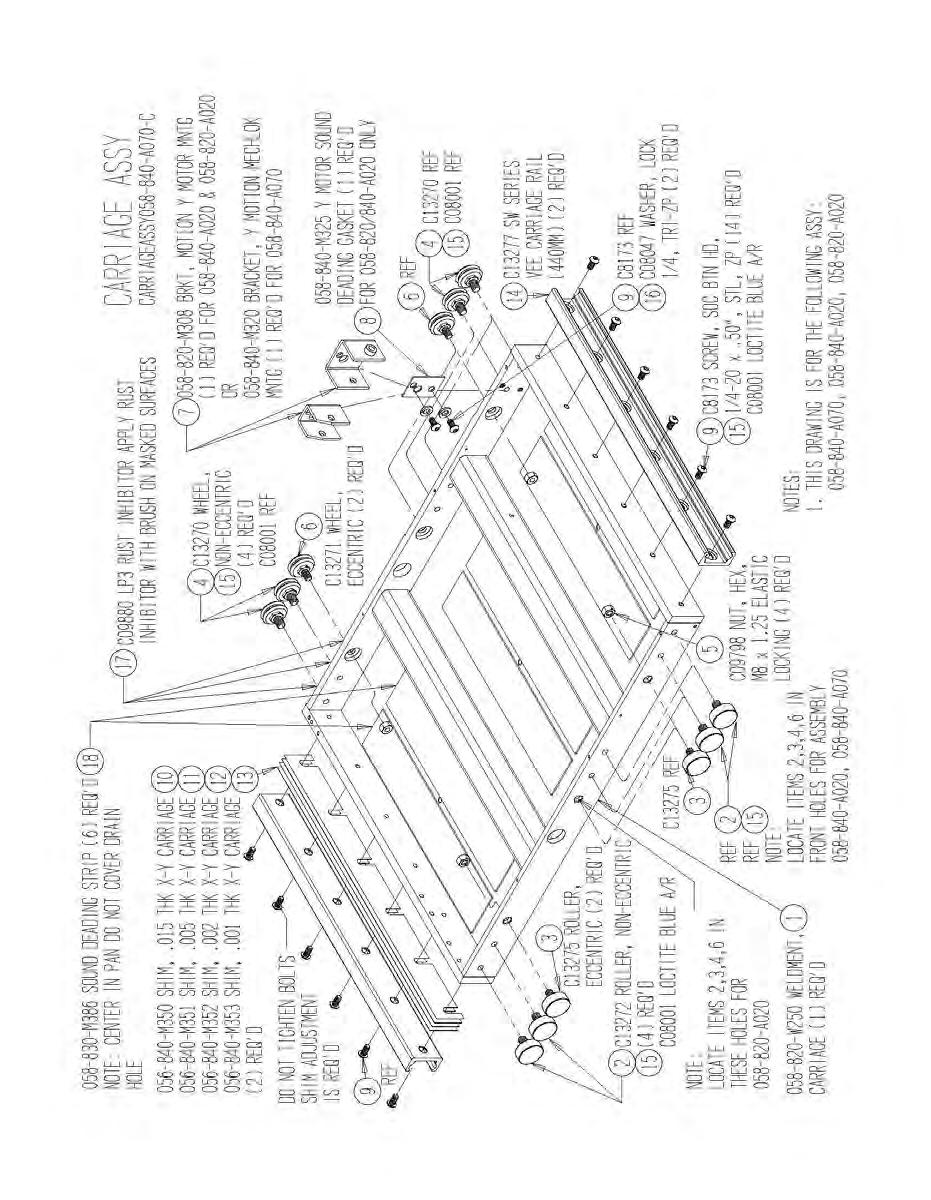
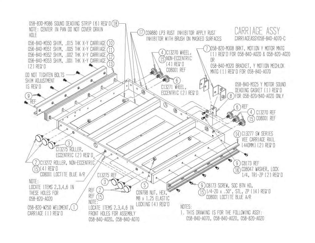
10 3. Y MOVEMENT ACTUATOR REPLACEMENT, (LATERAL) Tools Required: Phillips screwdriver, Allen keys Socket set, standard Wire cutters REMOVAL 1. Activate the X motor and move the tabletop all the way towards the back. 2. Remove the four 9/16th bolts, which are now accessible from the underside of the tabletop (see Figure 3.1). 3. Activate X motor and move the tabletop all the way forward. 4. Support the tabletop, before removing the final four 9/16th bolts, which are accessible from the forward underside of table. 5. Remove the four remaining bolts and lift to remove the tabletop. Once the tabletop is removed you will have access to the X actuator as shown in Figure Remove the two Phillip screws holding the resistor strip wiper bracket (see Figure 3.2). 7. Remove the four hex head bolts located in the side of the Y-motor nut mounting bracket. NOTE: Do not remove the Allen screws holding the rollers. 8. Remove the two 3/16 Allen bolts holding the actuator collar to the Y-motor nut-mounting bracket (see Figure 3.3). 9. Remove the C-clip and pin holding the actuator to the clevis bracket. 10. Disconnect the power connector and remove the actuator. INSTALLATION NOTE: The actuator needs to be calibrated after installation. 1. Install the new actuator to the clevis bracket. 2. Install the actuator collar to the Y-motor nut mounting bracket with the flat side of the collar facing away from the bracket. 3. Install the Y-motor nut mounting bracket to the frame using the four hex bolts. Refer to assembly drawing, Surgical C-Arm, for reference. 4. The collar on the worm gear should now be facing down towards the base weldment. Run the actuator through its min and max range to make sure is moves without restriction and runs quietly. 5. Install tabletop. 6. Calibrate table as instructed in Chapter 11, Calibration Procedure. 10

11 Figure 3.1. Resistor strip wiper Y position resistor strip Y-motor Wiper bracket securing screws Y-motor nut mounting bracket Four 7/16 hex bolt securing nut mounting bracket Figure /16 Allen bolt securing actuator collar to bracket Actuator clevis with securing pin and C clip Figure
12 4. LIFT ACTUATOR REPLACEMENT Tools Required: Phillips screwdriver 5 mm Allen key 8 mm wrench PROCEDURE 1. If the lift actuator is operational, the table should be brought down to its lowest position. If the actuator is not operational, the tabletop must be supported to prevent it from falling once the actuator is removed. 2. Lower the tabletop to its lowest position and remove the 18 Phillips screws that secure the lower portion of the bellows. 3. Remove the eight Phillips screws securing the top covers, and remove one cover at a time. 4. Remove the lower right cover secured with nine Phillips screws. 5. Remove the lower back panel (see Chapter 1, Control Module Replacement). Only three panels now remain on the right side since you should have already removed the lower left panel. NOTE: Be sure to support the tabletop on both ends to prevent it from dropping once the lift actuator is removed. 6. The actuator is secured at both ends with a 5-mm Allen head shoulder bolt and an 8-mm nut. (Figure 4.1 shows the lift actuator bottom-securing bolt. Figure 4.2 shows the lift actuator upper securing bolt.) 7. Remove the actuator and unplug the actuator power cable at the RCA jack on the controller box. (Figure 4.3 shows the control box and vertical lift actuator RCA plug location. Also, refer to the parts section drawing labeled I-Base Assy. for assembly components and part numbers.) NOTE: For reinstallation of the actuator, reverse the process and test for proper operation before installing the enclosures. 12


13 Lift actuator lower bolt and nut Figure 4.1. Lift actuator upper bolt and nut Figure 4.2. The Control box is secured with six nuts Calibration port LCD display cable X, Y, tilt position sense Hand/Foot control cable Main power coiled cable for X and Y roll actuator Trendelenburg actuator Figure 4.3. AC pwr/battery Vertical actuator 13
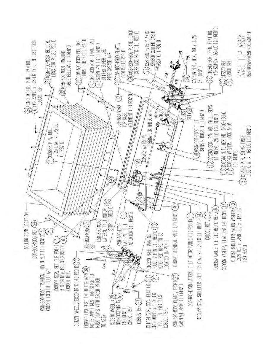
14 5. LATERAL TILT ACTUATOR REPLACEMENT Tools Required: Phillips screwdriver 3/16" Allen key 1/2" wrench PROCEDURE 1. If the lateral tilt actuator is operational, tilt it down on the patient right side. The table should be brought head down to its lowest position. If the actuator is not operational, the tabletop must be supported to prevent the tabletop from suddenly tilting once the actuator is removed. 2. The actuator is located inside the bellow on the patient right side. Remove the 18 Phillips screws that secure the lower portion of the bellows. 3. Remove the eight Phillips screws that secure the top covers, and then remove the covers one at a time. 4. Remove the lower right cover that is secured with nine Phillips screws. 5. Remove the lower back panel. (Six screws secure the lower back panel, but only three remain on the right side since you should have already removed the lower left panel.) NOTE: Be sure to support the tabletop to prevent it from dropping once the lateral tilt actuator is removed. 6. The actuator is secured to the table with a 3/16-inch Allen head shoulder bolt and 1/2-inch nut. (Figure 5.1 shows the securing bolt assembly). In addition, the acme nut is secured with two 3/16-inch bolts. (Figure 5.2 shows the acme nut assembly.) 7. Remove the actuator and unplug the actuator power cable at connector #3 on the controller box. (Figure 5.3 shows the control box and actuator plug location #3. Also refer to the parts section drawing, labeled Base Top Assembly for assembly components and part numbers.) NOTE: For reinstallation of the actuator, reverse the process and test for proper operation before installing the enclosures. 14


15 Securing bolt and nut Figure /18 head bolts Figure 5.2. The Control box is secured with six nuts Calibration port LCD display cable X, Y, tilt position sense Hand/Foot control cable Main power coiled cable for X and Y roll actuator Trendelenburg actuator Figure 5.3. AC pwr/battery Vertical actuator 15
16 6. HEAD-TO-TOE TILT ACTUATOR REPLACEMENT Tools Required: Phillips screwdriver PROCEDURE 1. If the tilt actuator is operational, the table should be brought head down to its lowest position. If the actuator is not operational, the tabletop must be supported to prevent the top from suddenly tilting once the actuator is removed. 2. Tilt the top head down to its lowest position, and remove the eighteen Phillips screws that secure the lower portion of the bellows. 3. Remove the eight Phillips screws securing the top covers, and then remove the covers one at a time. 4. Remove the lower right cover secured with nine Phillips screws. 5. Remove the lower back panel. (Six screws secure the lower back cover, but only three remain on the right side since you should have already removed the lower left panel.) NOTE: Support the tabletop to prevent it from dropping once the tilt actuator is removed. 6. The actuator is secured at both ends with a pin and C-clip. Remove the clip and pull the pins out. (Figure 6.1 shows the lift actuator bottom-securing bolt. Figure 6.2 shows the lift actuator upper securing bolt. Refer to the illustrated parts section with the page entitled I - Base Assy, see item #51.) 7. Remove the actuator and unplug the actuator power cable at the RCA connector on the controller box. Figure 6.3 shows the control box and actuator plug location. NOTE: To reinstall the actuator, reverse the process and test for proper operation before installing the enclosures. 16


17 Actuator lower securing pin and clip Figure 6.1. Actuator upper securing pin and clip Figure 6.2. Trendelenburg actuator Figure
18 7. TABLETOP REPLACEMENT Tools Required: 9/16" wrench PROCEDURE 1. Activate the X motor and move the tabletop all the way towards the back. 2. Remove the four 9/16-inch bolts, which are now accessible from the underside of the tabletop (see Figure 7.1). 3. Activate the X motor and move the tabletop all the way forward. 4. Support the tabletop before removing the final four 9/16-inch bolts that are accessible from the forward underside of table. 5. Remove the four remaining bolts and lift to remove the tabletop. Figure
... Front/Back (X axis...roll Tools Required: Phillips screwdriver PROCEDURE Figure 8.1 shows the control board layout.")
19 8. CONTROLLER BOX REPLACEABLE COMPONENT H-bridge motor controller boards 5v logic supply fuse Fowler back 24v Power supply fuses for motors Power supply board UP/Down Pitch Figure 8.1. Side to Side (Y axis)... Front/Back (X axis...roll Tools Required: Phillips screwdriver PROCEDURE Figure 8.1 shows the control board layout. There are six board slots, which are labeled to designate their function. Each board activates a specific actuator or solenoid. The control board is configured to the table type it is used in. The control box is configured for a table - that is why the last slot J8 (Fowler Back) is not used. Slot Designations J3 J4 J5 J6 J7 J8 Function Up/Down Pitch (head to toe tilt) Roll (side to side tilt) Front to Back (x axis) Side to Side (y axis) Fowler back Replaceable Components Fuses are located on the power supply board as identified above. The motor fuses (2) are 15- amp and the display/logic is 2-amp. To replace, simply pull straight out from the socket. To replace the H-bridge motor controller board, pull straight up. To easily identify if board is defective replace with board from a known operating motor. When installing boards, line up pins on board with connector and press down evenly. To replace the Power Supply board, remove the four Phillips screws located at each corner. Next, disconnect the three connectors, J3, J5 &J6. The above component replacement does not require that the table be recalibrated; however verification of proper operation is required. 19

20 9. TILT SENSOR BOARD REMOVAL AND REPLACEMENT Connector Tilt Sensor Board Figure 9.1. Tools Required: Phillips screwdriver PROCEDURE The tilt sensor is under the tabletop, on the patient left side next to lateral tilt actuator. 1. Raise table to maximum height, for better accessibility. 2. Remove the eighteen Phillips screw securing the lower portion of the bellow. 3. Lift the bellows and secure in the up position. This provides you with access to the sensor. 4. Disconnect the signal cable connector. 5. Remove the three Phillips screws securing the sensor board. 6. To reinstall the Tilt Sensor board, reverse the procedure above. For a detailed illustration refer to Chapter 16, Part and Assembly Illustrations. NOTE: The table must be recalibrated when a new sensor is installed. Refer to Chapter 11, Calibration Procedure for instructions. 20


21 10. POSITION SENSING STRIP REPLACEMENT Tools Required: Phillips screwdriver PROCEDURE The table utilizes three precision resistor strips to sense the table s height and X, Y tabletop position. Figure 10-1 shows the resistor strip installed on the table. The wiper/roller move along the resistor strip as the position of the table changes. The resistance change is in direct correlation to the wiper position. Any changes in resistance are converted to position counts, which are shown on the display. NOTE: Refer to Chapter 4, Lift Acutator Replacement, steps one through four, to access the position strip for ion strip for replacement. Resistor wiper Resistor strip Figure Height position sensing resistor strip. Resistor connector Resistor strip Resistor wiper Figure Y position sensing resistor strip (solenoid assembly, tabletop removed.) 21
 Resistor strip Resistor wipes Figure 10.4.")
 REPLACING THE RESISTOR STRIP To replace the resistor strip, remove the two securing screws.")

22 Resistor strip wiper Y position resister strip Y-motor Wiper bracket securing screws Figure Y position sensing resistor strip (actuator assembly, tabletop removed.) Resistor strip Resistor wipes Figure X position sensing resistor strip (tabletop removed for viewing.) REPLACING THE RESISTOR STRIP To replace the resistor strip, remove the two securing screws. Next, lift wiper/roller and remove the strip (strip may also be secured with adhesive). When any sensor is replaced a table calibration is required. Refer to Chapter 11, Calibration Procedure, for instructions. Figure Resistor strip not installed. Note that the strip is secured with adhesive to a thin metal mounting plate. The mounting plate is attached to the designated location with two Phillips screws at each end. 22
23 11. TABLE CALIBRATION PROCEDURE Tools Required: PC with latest table calibration software installed PROCEDURE 1. Connect COMM PORT 1 of the PC to the 9 pin male "D" connector of the table s control box, using a 9 pin female to 9 pin female RS-232 cable. 2. Turn the computer and monitor on. 3. When Windows is finished booting, double-click the left mouse button on the Image Table icon on the PC's desktop, to start the utility software. 4. Enter the table serial number in the appropriate box in the utility software. 5. Turn the table ON. "Welcome", "Press C to Calibrate" and other information or characters may be displayed in the software's receive window. 6. Click the left mouse button on "CALIBRATE." "++++ IMAGE TABLE CALIBRATION ++++" will be displayed in the software's receive window. 7. Follow the on-screen prompts in the utility's receive window. 8. The current selection for the type of table is displayed. This can be changed by pressing "Y" on the keyboard. 9. The table type choices are: 1) 830/870/C-ARM, 2) 840 Float Top, 3) Lithotripsy, 4) 800/810 URO/BRACH. Select the correct table type by pressing number 1-4 on the keyboard. 10. The current selection for the type of motor installed is displayed. The motor type choice is either High Speed or Low Speed. If this is incorrect, the motor type can be changed by pressing "Y" on the keyboard, otherwise press "N". 11. You will be given the option to calibrate each of the following: UP/DOWN FORWARD/BACK SIDE TO SIDE JOYSTICK PITCH Axis ROLL Axis 12. Select "Y" for each and follow the on-screen prompts. 13. To Calibrate UP/DOWN: a. Press the appropriate UP or DOWN hand switch button so that "+ +" is displayed in the utility's receive window. b. When the MAX Position is reached, reverse direction momentarily to back away from the MAX Position slightly, then press any key to set position. c. Press the appropriate UP or DOWN hand switch button so that "- -" is displayed in the utility's receive window. d. When the MAX Position is reached, reverse direction momentarily to back away from the MAX Position slightly, then press any key to set position. 23
24 14. Calibrate FORWARD/BACK: a. Press the appropriate FORWARD or BACK hand switch button so that "+ +" is displayed in the utility's receive window. b. When the MAX Position is reached, reverse direction momentarily to back away from the MAX Position slightly, then press any key to set position. c. Press the appropriate FORWARD or BACK hand switch button so that "- -" is displayed in the utility's receive window. d. When the MAX Position is reached, reverse direction momentarily to back away from the MAX Position slightly, then press any key to set position. 15. Calibrate SIDE TO SIDE: a. Press the appropriate LEFT or RIGHT hand switch button so that "+ +" is displayed in the utility's receive window. b. When the MAX Position is reached, reverse direction momentarily to back away from the MAX Position slightly, then press any key to set position. c. Press the appropriate LEFT or RIGHT hand switch button so that "- -" is displayed in the utility's receive window. d. When the MAX Position is reached, reverse direction momentarily to back away from the MAX Position slightly, then press any key to set position. 16. Calibrate PITCH Axis: a. Press the appropriate PITCH hand switch button so that "+ +" is displayed in the utility's receive window. b. When you reach 20 degrees position, reverse direction momentarily to back away slightly, then press any key to set position. c. Press the appropriate PITCH hand switch button so that "- -" is displayed in the utility's receive window. d. When you reach 20 degrees position, reverse direction momentarily to back away slighly, then press any key to set position. 17. Calibrate ROLL Axis: a. Press the appropriate ROLL hand switch button so that "+ +" is displayed in the utility's receive window. b. Press any key when 18 DEGREES TILT is reached. c. Press the appropriate ROLL hand switch button so that "- -" is displayed in the utility's receive window. d. Press any key when 18 DEGREES TILT is reached. 24
25 18. You will be asked if you need to change the HOME Position. Move the table to the NEW HOME Position, then press any key. NOTE: The table must have the HOME position set to Full Down, Full Back, and Left/Right Centered. 19. When "****** EXIT Calibration MODE ******" is displayed you can choose to discard the previous calibration by pressing "C" to recalibrate, or save the calibration by pressing "S," or load a saved calibration by pressing "L". 20. When you are satisfied with the calibration, press "S" to save the calibration. Various numbers and letters will scroll by in the software's receive window. 21. The Imaging Table Calibration Utility may be exited by clicking File --> Exit on the menu bar or by clicking the X in the upper right corner. 25
. 1. Lift head end of table so that casters are six inches off the floor. 2.")
26 12. CASTER REPLACEMENT Tools Required: 9/16 Allen key 1/2 wrench ¾ wrench (thin) HEAD END CASTER REPLACEMENT The two head casters lock simultaneously by depressing either the left or right pedal. They are connected via a hex shaft. (see Figure 12.1). 1. Lift head end of table so that casters are six inches off the floor. 2. Remove each pedal weldment (left and right), which are secured with two 9/64 allen head screw and slide hex shaft out. 3. Remove the two 1/2-inch hex bolts from each of the caster mount and slide casters out. (see Figure 12.1) FOOT END CASTER REPLACEMENT 1. Lift head and foot end of table so that casters are six inches off the floor. 2. Each caster is secured with a ¾-inch hex stud. To remove caster a special thin ¾-inch wrench is required. When replacing caster use Loctite blue on treads. Figure Caster replacement. 26
27 13. TABLE FIRMWARE UPDATE 1. Connect the PC to the 9 pin female "D" connector of the control box, using the special 9 pin female to 9 pin male DSP programming cable. 2. Turn the computer and monitor on. 3. Turn the table on. 4. When Windows is finished booting, double-click the left mouse button on the Image table icon on the PC's desktop to start the utility software. 5. Enter the table serial number in the appropriate box in the utility software. 6. Click on the PROGRAM LCB to begin the firmware update. 7. When the update is complete, close any newly opened windows by clicking the X in the upper right corner of each window. 8. The Imaging Table Calibration Utility may be exited by clicking File --> Exit on the menu bar or by clicking the X in the upper right corner. 27

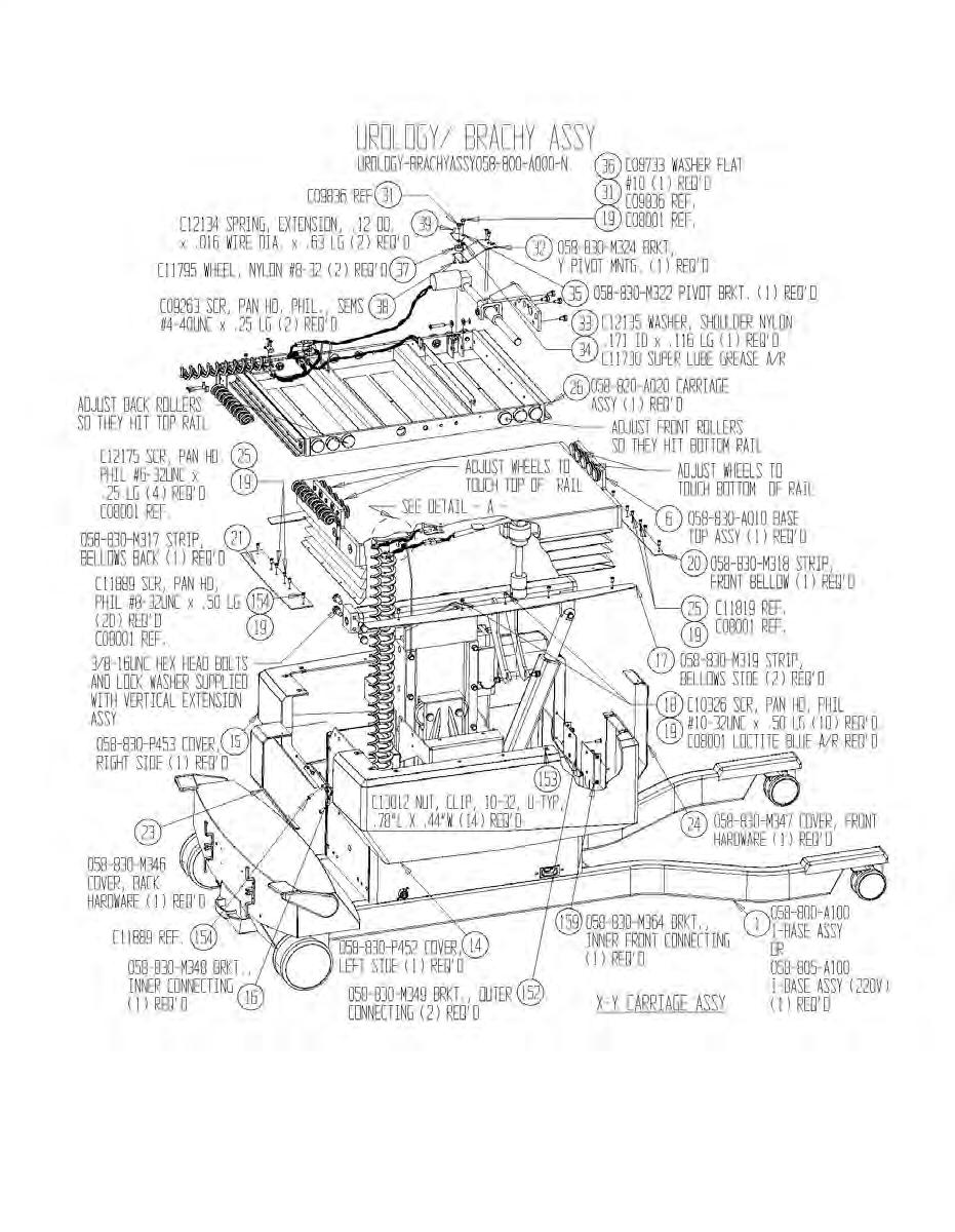
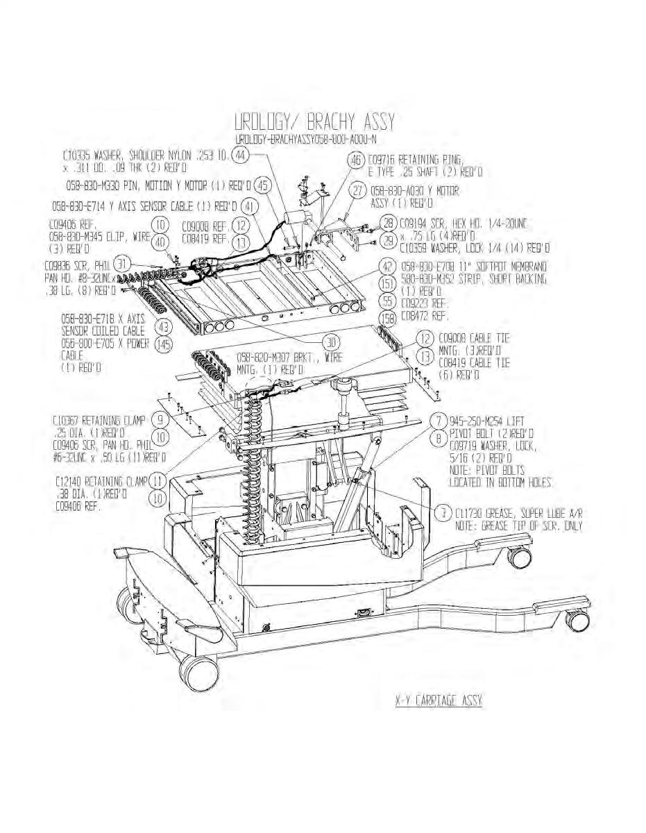
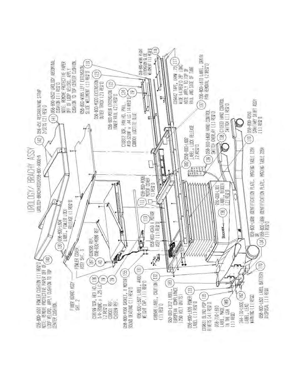
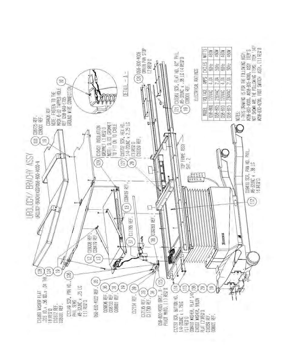
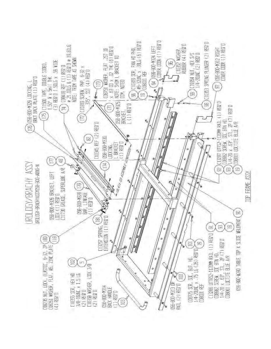
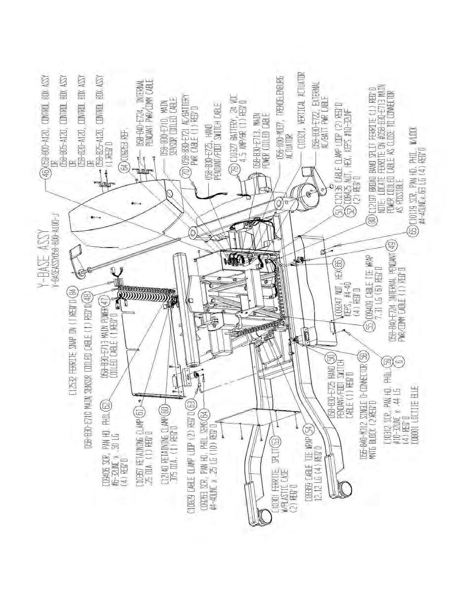
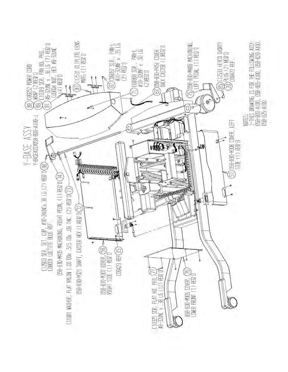
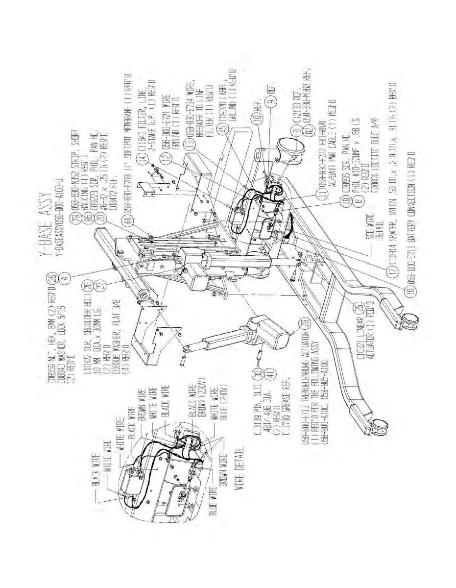
28 14. Part And Assembly Illustrations 28
29 29
30 30
31 31

32 32
33 33
34 34
35 35
36 36

37 37
38 38
39 39
40 40
41 41
42 42
43 43
44 44
45 45
46 46
47 47
48 48

49 49
50 BIODEX Biodex Medical Systems, Inc. 20 Ramsey Road, Shirley, New York, , Tel: (Int l ), Fax: , info@biodex.com, 52
PET UNIT DOSE TABLE INSTALLATION MANUAL FN: Rev A 1/18
 PET UNIT DOSE TABLE INSTALLATION MANUAL 042-448 FN: 09-243 Rev A 1/18 Pet Unit Dose Table This manual covers installation procedures for the following products: 042-448 Table, PET, Unit Dose 2 Biodex Medical
SIT2STAND TM TRAINER INSTALLATION AND ASSEMBLY GUIDE FN: /15
 SIT2STAND TM TRAINER INSTALLATION AND ASSEMBLY GUIDE 950-560-10 FN: 15-460 11/15 This manual contains operating procedures for the following Biodex product: 950-560 Sit2Stand Trainer Contact Information
PET UNIT DOSE CABINET
 PET UNIT DOSE CABINET INSTALLATION MANUAL 244-200 244-205 FN: 08-134 Rev A 11/17 Pet Unit Dose Cabinet This manual covers operation procedures for the following products: 244-200 Cabinet, PET, Unit Dose
USER GUIDE 1 USER GUIDE
 USER GUIDE 1 USER GUIDE 1 TABLE OF CONTENTS IN THE BOX...3 NAVIGATING THE MENUS...3 MENU LAYOUT...3 UPDATE YOUR PROGRAMMER...4 CONNECT WITH THE MOTORCYCLE...5 TUNE YOUR MOTORCYCLE...6 ADDITIONAL FEATURES...8
INSTALLATION INSTRUCTIONS for the LR Chair
 INSTALLATION INSTRUCTIONS for the LR Chair SECTION I - REQUIREMENTS 1. PHYSICAL REQUIREMENTS... 1 2. ELECTRICAL REQUIREMENTS... 1 SECTION II - INSTALLATION 1. UNPACKING THE CARTONS... 2 2. UNPACKING THE
Instruction Sheet SRSR SERIES. Rotating Sliding Rail System
 Instruction Sheet SRSR SERIES Rotating Sliding Rail System THANK YOU Thank you for purchasing the SRSR Series Rotating Sliding Rail System. Please read these instructions thoroughly before assembling this
Case IH 3320, 3330, and Booms AutoBoom Installation Manual. P/N Rev B 06/15
 Case IH 3320, 3330, and 4420-0120 Booms AutoBoom Installation Manual P/N 016-0230-091 Rev B 06/15 Copyright 2009 Disclaimer While every effort has been made to ensure the accuracy of this document, Raven
Adjustable Base. CONTENTS Advisory Setup and Installation Innova Wired Hand Control year Warranty 1-10
 Adjustable Base #201 Wired Owner Manual CONTENTS Advisory Setup and Installation Innova Wired Hand Control 1-2-10 year Warranty 1-10 WARNING Attention: Read the following information before using this
Model:M5B/M5W/M5N. Installation Guide. Specifications Desktop Weight Capacity Keyboard Tray Weight Capacity Height Adjustable Range
 Model:M5B/M5W/M5N Installation Guide Website: www.flexispot.com Tel: 1-855-421-2808 Specifications Desktop Weight Capacity Keyboard Tray Weight Capacity Height Adjustable Range 33 Ibs (15 KG) 4.4 Ibs (2
IMPORTANT! 09 to Current Straight Up Electric Billet Center Stand. Dealer and/or Customer must complete the following items: Center Stand Checklist
 IMPORTANT! 09 to Current Straight Up Electric Billet Center Stand Dealer and/or Customer must complete the following items: Center Stand Checklist 1. Complete the Measurement Guide 2. Read the Operation
IAQ-CALC INDOOR AIR QUALITY METER MODEL 7515
 IAQ-CALC INDOOR AIR QUALITY METER MODEL 7515 OPERATION AND SERVICE MANUAL P/N 1980571, REVISION D FEBRUARY 2016 Copyright TSI Incorporated / May 2007-2016 / All rights reserved. Address TSI Incorporated
Sport Coil Springs (19425) Scion tc
 Scion tc") Sport Coil Springs (19425) Scion tc Thank you for your purchase from our new line of Scion tc parts. Please call us at (877) 4NO-ROLL if you have any questions regarding the service or installation of
Sport Coil Springs (19425) Scion tc Thank you for your purchase from our new line of Scion tc parts. Please call us at (877) 4NO-ROLL if you have any questions regarding the service or installation of
CM1000C CM1800C ChangeMakers. Operator s Manual. Seaga Manufacturing, Inc. 700 Seaga Drive Freeport, IL USA
 CM1000C CM1800C ChangeMakers Operator s Manual Seaga Manufacturing, Inc. 700 Seaga Drive Freeport, IL USA 61032 www.seagamfg.com INTRODUCTION Congratulations on the purchase of your new ChangeMaker. This
FlexChem Model 404 Rotating Oven
 www.scigene.com FlexChem Model 404 Rotating Oven USER MANUAL Cat. #1052-20-1, 1052-20-2, 1052-22-1 & 1052-22-2 FOR RESEARCH USE ONLY Not for Use in Diagnostic Procedures SciGene 306 Potrero Ave, Sunnyvale,
04 & 14 F FRONT 1.0 REAR LEVELING KIT INSTALLATION
 INSTRUCTION PART NO 15312 KIT NO 3836 04 & 14 F-150 2.0 FRONT 1.0 REAR LEVELING KIT INSTALLATION READ INSTRUCTIONS COMPLETELY THROUGH BEFORE STARTING. FAILURE TO ADHERE TO THE INSTRUCTIONS WILL VOID ANY
Instruction Sheet DWRSR-ZL. Zero Clearance Latch
 Instruction Sheet DWRSR-ZL Zero Clearance Latch US Patent 7,188,570 B2 THANK YOU Thank you for purchasing the DWRSR-ZL Zero Clearance Latch. Please read these instructions thoroughly before installing
Operation Instructions
 Rice Lake Mechanical Physician Scale Model RL-MPS, RL-MPS-10, RS-MPS-20 Operation Instructions To be the best by every measure 102696 Contents 1.0 Introduction... 1 2.0 Installation Instructions... 2
Installation & Operators Manual
 Installation & Operators Manual Model Serial Number Purchase Date 2007-2008 SegVator, LLC Patent Pending All Rights Reserved Important Safety Information Make sure the vehicle has a properly installed
Model 1100B CHG Terminator. Installation Instructions
 Model 1100B CHG Terminator Installation Instructions 1 Contents: 1.0 Safety Information... 3 2.0 Set-up and Adjustments... 3 3.0 Ram Adjustments... 10 4.0 Wire Termination Quality... 12 5.0 General Maintenance...
CSA CERTIFIED Conforms to UL 507
 Installation tion Instructions Please read and save these instructions! TURBO/MAXX12 Volt All Weather RV Ventilator Fans P/N 00-965001 Deluxe Model 1200T WITH THERMOSTAT P/N 00-965007 Standard Model 3550
Hypertech Speedometer Calibrator Module Installation Instructions. PN Toyota Tundra & Sequoia
 Hypertech Speedometer Calibrator Module Installation Instructions PN730119 2014-2018 Toyota Tundra & 2014-2016 Sequoia This installation manual shows an example installation on Toyota Tundra vehicles.
INSTALLATION INSTRUCTIONS THERMOCOUPLE EXPANSION MODULE
 INSTALLATION INSTRUCTIONS THERMOCOUPLE EXPANSION MODULE 2650-1846-77 Rev. B Details: Temperature Rating: -40 C to 85 C/-40 F to 185 F Vibration Specification: 20 g continuous, 50 g shock Inputs: o 4 EGT
Easy Packer. Industrial Case Erecting, Packing and Taping System. User Guide
 Easy Packer Industrial Case Erecting, Packing and Taping System User Guide Easy Packer Industrial Case Erecting, Packing and Taping System User Guide Revised 04/19/2012 P/N XXXXXXX Rev A Copyright and
Model A Turn Signal Kit Installation Guide
 Model A Turn Signal Kit Installation Guide Creative Connections, Inc. Consumer Hot Line: 888-471-LOGO 770-476-7322 In Atlanta, GA http://www.logolites.com P/N: 100-005/K 2008 Creative Connections, Inc.
Installation Instructions. PowerFlex 700 Drive - Frame 8 Components Replacement
 Installation Instructions PowerFlex 700 Drive - Frame 8 Components Replacement Important User Information Solid-state equipment has operational characteristics differing from those of electromechanical
MODEL 5120 Tire Repair Station
 MODEL 5120 Tire Repair Station 00-0049 Installation, Operation & Repair Parts Information Branick Industries, Inc. 4245 Main Avenue P.O. Box 1937 Fargo, North Dakota 58103 REV01182017 P/N: 81-0058G CAUTION
ONBOARD AIR HOOKUP KIT
 ONBOARD AIR HOOKUP KIT PART NO. 20052 (30 amp - 110PSI on, 150PSI off) PART NO. 20053 (30 amp - 85PSI on, 105 PSI off) PART NO. 20055 (30 amp - 90 PSI on, 120 PSI off) IMPORTANT: It is essential that you
Installation Instructions for Lingenfelter GM 2500 Suburban & Yukon XL Auxiliary Fan System (with AC clutch controlled fan output)
") Installation Instructions for Lingenfelter 2007-2013 GM 2500 Suburban & Yukon XL Auxiliary Fan System (with AC clutch controlled fan output) PN L300080607 Revision - 1.1 Lingenfelter Performance Engineering
Installation Instructions for Lingenfelter 2007-2013 GM 2500 Suburban & Yukon XL Auxiliary Fan System (with AC clutch controlled fan output) PN L300080607 Revision - 1.1 Lingenfelter Performance Engineering
Pride Mobility Products Corporation
 TM Versa Tilt Seating System Basic Operation Instructions 2 Pride Mobility Products Corp. Versa Tilt IMPORTANT NOTICE This manual describes basic operation for the Versa Tilt only and must be read in conjunction
Model 700 Microarray Oven
 www.scigene.com Model 700 Microarray Oven USER MANUAL Cat. #1070-00-1, 1070-00-2 FOR RESEARCH USE ONLY Not for Use in Diagnostic Procedures SciGene 306 Potrero Ave, Sunnyvale, CA 94085 USA 408-733-7337
Model 809 Diaphragm Gauge Controller
 Instruction Manual Model 809 Diaphragm Gauge Controller Copyright 2004 by Duniway Stockroom Corp. rev120313sr TELEPHONE: 650-969-8811 TOLL-FREE: 800-446-8811 FAX: 650-965-0764 WWW.DUNIWAY.COM 1 of 17 Table
Installation Instructions
 Installation Instructions Bradley Touch Time Valve for Column Showers Table of Contents Pre-Installation Information...............2 Touch Time Valve Installation............3 Touch Time Valve Wiring Diagram........4
3100 ELITE SERIES SURGICAL TABLES
 PARTS CATALOG 3100 ELITE SERIES SURGICAL TABLES Page i 1. Top & Side Frame Assemblies................. Page 2 2. Side Frame & Hydraulic Cylinders............. Page 6 3. Support Column Assembly...................
OWNER S MANUAL MODEL # TGL-500 HITCH LIFT
 OWNER S MANUAL MODEL # TGL-500 HITCH LIFT For Customer Service Call or Fax 1 (800) 87-LARIN 1 SPECIFICATIONS.. Max Capacity:.500 lbs. Motor Power: 12 VDC SPECIFICATIONS ARE SUBJECT TO CHANGE WITHOUT NOTICE
User Manual SH Slag Removal Tool for use on laser cutting machines with minimum 1.25 between slats
 User Manual SH2 67087 Slag Removal Tool for use on laser cutting machines with minimum 1.25 between slats 1. Description The tool is moved along the slats on the bed of a laser machine to remove slag that
Sport Coil Springs set # Cadillac CTS
 Sport Coil Springs set # 1979 2003+ Cadillac CTS Thank you for your purchase from our new line of CTS parts. Please call us at (877) 4NO-ROLL if you have any questions regarding the service or installation
Anthro Mobile Device Charging Carts and Cabinets Owners Manual
 Anthro Mobile Device Charging Carts and Cabinets Owners Manual TECHNOLOGY FURNITURE Hello! Thank you for choosing Anthro. Anthro's Tablet Charging Carts and Cabinets are designed to automatically charge
Electric Pilot System Assembly, Operation, & Maintenance
 Electric Pilot System Assembly, Operation, & Maintenance Congratulations on your purchase, and thank you for selecting the Electric Pilot System from Blichmann Engineering Pro Series. We are confident
Instruction Manual Installation and Operation Guidelines for DWL5000XY and DWL5500XY Tilt Sensor Modules (Version 2.2)
") Instruction Manual Installation and Operation Guidelines for DWL5000XY and DWL5500XY Tilt Sensor Modules (Version 2.2) INTELLECTUAL PROPERTY This manual contains propriety information, which is protected
Instruction Manual Installation and Operation Guidelines for DWL5000XY and DWL5500XY Tilt Sensor Modules (Version 2.2) INTELLECTUAL PROPERTY This manual contains propriety information, which is protected
ELITE SERIES SURGICAL TABLES
 Page 39 Item Part No. Description Qty. ELITE SERIES SURGICAL TABLES PARTS CATALOG MODEL ELITE 3500 Page 1 Item Part No. Description Qty. INTRODUCTION This manual contains the exploded views and replacement
MEX (55) QRO (442) Web Controls
 QRO (442) Web Controls") Web Controls SINGLE AND DUAL ROTOR TENSION CONTROL BRAKES MODELS:,,,, AND INSTALLATION, OPERATION, AND MAINTENANCE INSTRUCTIONS Read this manual carefully, making full use of its explanations and instructions.
Web Controls SINGLE AND DUAL ROTOR TENSION CONTROL BRAKES MODELS:,,,, AND INSTALLATION, OPERATION, AND MAINTENANCE INSTRUCTIONS Read this manual carefully, making full use of its explanations and instructions.
Case IH Puma and New Holland T70X0/T7.XXX - Steering Ready SmarTrax Installation Manual. P/N Rev B 09/15 E20796
 Case IH Puma and New Holland T70X0/T7.XXX - Steering Ready SmarTrax Installation Manual P/N 016-5032-007 Rev B 09/15 E20796 Copyright 2012, 2013, 2015 Disclaimer While every effort has been made to ensure
TO ORDER PARTS CALL: (479) or
 or") Owner s Manual Industrial Ergonomic User-Friendly Hand Controls Date Manufactured: / / o Mart Cart XTi 24 Model 03522 - SKU# 280-3522 o Mart Cart XTi 24 Model 03524 - SKU# 280-3524 CONGRATULATIONS You
Owner s Manual Industrial Ergonomic User-Friendly Hand Controls Date Manufactured: / / o Mart Cart XTi 24 Model 03522 - SKU# 280-3522 o Mart Cart XTi 24 Model 03524 - SKU# 280-3524 CONGRATULATIONS You
JOHN DEERE 9970 COTTON PICKERS
 PARTS CATALOG FOR Mud Hog System II Rear Wheel Drive FOR JOHN DEERE 9970 COTTON PICKERS Mud Hog Model Numbers Tread Center OEM Aftermarket JD40005 JD47655 82, 90, 94, 106 TUTHILL Drive Systems 9098 West
P44 Stepper. User Manual
 P44 Stepper User Manual Table of Contents Introduction 1 Safety Warning 2 Overview of Parts 2 Attaching to Chair 3 Manoeuvring Around 4 Setting Pedal Stops 4 Getting On 5 Setting the Resistance (models
The Da-Lite Difference.
 The Da-Lite Difference. Instruction Book for Boardroom Electrol DA-LITE SCREEN COMPANY, INC. 3100 North Detroit Street Post Office Box 137 Warsaw, Indiana 46581-0137 Phone: 574-267-8101 800-622-3737 Fax:
CARBURETOR REBUILD KIT (Vacuum Secondary) Models Demon Carburetors & Holley Model 4160 LIT704
 Models Demon Carburetors & Holley Model 4160 LIT704") CARBURETOR REBUILD KIT 190000 (Vacuum Secondary) Models Demon Carburetors & Holley Model 4160 LIT704 INSTRUCTIONS: Before getting to the actual rebuild, it should be noted that the carbs shown here are
CARBURETOR REBUILD KIT 190000 (Vacuum Secondary) Models Demon Carburetors & Holley Model 4160 LIT704 INSTRUCTIONS: Before getting to the actual rebuild, it should be noted that the carbs shown here are
OPW Installation and Maintenance Instructions OPW Series Primary and Secondary Bucket Replacement Instructions
 OPW Installation and Maintenance Instructions OPW 1-3100 Series Primary and Secondary Bucket Replacement Instructions IMPORTANT: Please read these warnings and follow the assembly instructions completely
AutoBoom Installation Manual
 AutoBoom Installation Manual CaseIH 3150/3185, Pre-2002 Tyler Patriot Open Center Disclaimer While every effort has been made to ensure the accuracy of this document, Raven Industries assumes no responsibility
Black Diamond Motorized Flush Mount Instructions
 Black Diamond Motorized Flush Mount Instructions 1 Installation Parts List Mounting Brackets Wall Switch / Limit Setting Tool Mounting Bracket Screws & Driver Bit (#2 Robertson) Wall Switch Cable (8 Length)
CRD400 Fitting Inserter OPERATIONS MANUAL
 CRD400 Fitting Inserter OPERATIONS MANUAL ORIGINAL INSTRUCTIONS VERSION 3.4 LAST EDITED 01.07.2019 www.cleanroomdevices.com 1 Table of Contents Title Page.. 1 Table of Contents... 2 1.0 General Product
PCS GEAR SELECT MODULE USER GUIDE v4.0
 PCS GEAR SELECT MODULE USER GUIDE v4.0 Ph: 1.804.227.3023 www.powertraincontrolsolutions.com Powertrain Control Solutions 1 Introduction 1.1 Included Components 1 - GSM Cable Motor Enclosur 1 - GSM Driver
USER S OPERATING AND INSTRUCTION MANUAL
 Grand Rapids, Michigan, U.S.A. 49504-5298 USER S OPERATING AND INSTRUCTION MANUAL MODEL 797-21 BREAD SLICER 797S20000CV_21 THIS PAGE WAS INTENTIONALLY LEFT BLANK. GEN020319 RECOMMENDED
Read all instructions before installing and using. Installer: This manual must be delivered to the end user.
 Installation Instructions Vacuum / Magnet Mount Kits IMPORTANT! Read all instructions before installing and using. Installer: This manual must be delivered to the end user.! WARNING! Failure to install
INSTALLATION AND OPERATION MANUAL
 TRANSMISSION JACKS MODELS: RTJ-1 RTJ-660 RTJ-1100 RTJ-3000 PLEASE READ THE ENTIRE CONTENTS OF THIS MANUAL PRIOR TO INSTALLATION AND OPERATION. BY PROCEEDING YOU AGREE THAT YOU FULLY UNDERSTAND AND COMPREHEND
Telescopic Transmission Jacks
 Telescopic Transmission Jacks Operating Instructions & Parts Manual Model Number BH7051 BH7055 (Air/Manual) Capacity 1/2 Ton 1/2 Ton SFA Companies 2006 10939 N. Pomona Ave. Kansas City, MO 64153 816-891-6390
215E. Operator and Parts Manual MM158
 5E Operator and Parts Manual MM58 This manual is furnished with each new TENNANT Model 5E This manual consists of Specifications; Operation; Maintenance; Appendix; the How To Use This Manual; Low Dump
WANHAO Duplicator i3. User Manual V1.2. Wanhao USA
 WANHAO Duplicator i3 User Manual V1.2 Wanhao USA 2015 www.wanhaousa.com Safety WARNING: The components on the Duplicator i3 generate high temperatures and move extremely fast. Reaching inside of the Duplicator
SPORT COIL SPRINGS Scion xa & xb Part #19412 INSTALLATION OF HOTCHKIS FRONT COIL SPRINGS
 SPORT COIL SPRINGS 2004+ Scion xa & xb Part #19412 Thank you for your purchase from our new line of Scion xa / xb parts. Please call us at (877) 4NO-ROLL if you have any questions regarding the service
PowerMax Diesel Upgrade For Cummins Engines
 PowerMax Diesel Upgrade For Cummins Engines 00.5-007.5 Dodge Ram With Cummins 5.9L Item 3 4 5 6 7 8 9 0 3 4 5 6 7 8 Parts List Description Turbocharger Ancillary kit 773069- (includes) Installation Instructions
Instruction Book for. ContouR ElECtRol
 Instruction Book for ContouR ElECtRol IMPORTANT SAFETY INSTRUCTIONS When using your video equipment, basic safety precautions should always be followed, including the following: 1. Read and understand
150 PSI ILLUMINATED DASH PANEL GAUGE KIT
 150 PSI ILLUMINATED DASH PANEL GAUGE KIT PART NO. 10061 (For Use with 20/30 Amp Systems) PART NO. 20062 (For Use with 30/40 Amp Systems) IMPORTANT: It is essential that you and any other operator of this
STYLE 3463 FireFox. With Position Feedback Potentiometer
 STYLE 3463 FireFox INSTALLATION, OPERATING and MAINTENANCE INSTRUCTIONS With Position Feedback Potentiometer The following is intended to provide the basic instructions for installation, operating and
Buhler Versatile 23XX/24XX, Versatile 9X80, and New Holland Versatile 9X8X SmarTrax MD Installation Manual. P/N Rev A 04/16 E23635
 Buhler Versatile 23XX/24XX, Versatile 9X80, and New Holland Versatile 9X8X SmarTrax MD Installation Manual P/N 016-5030-065 Rev A 04/16 E23635 Copyright 2014, 2016 Disclaimer While every effort has been
MODEL EF Full Circle Tire Spreader
 MODEL EF Full Circle Tire Spreader Installation, Operation & Repair Parts Information Branick Industries, Inc. 4245 Main Avenue P.O. Box 1937 Fargo, North Dakota 58103 REV. 062917 P/N: 81-0050C CAUTION
Toggle Button Kit. Installation Instructions MK5 / MK6 Golf, MK5 Jetta
 Toggle Button Kit Installation Instructions MK5 / MK6 Golf, MK5 Jetta Thank you for choosing the Double Apex Toggle Button kit. If you have any questions about the installation please do not hesitate to
Installation Instructions
 Installation Instructions Automatic Retracting Running Board Vehicle Application Dodge Ram Quad Cab Pickup 2002-2005 Part Number: 75101-01 Dodge Ram Mega Cab Pickup 2006 - Current Part Number: 75118-01
Junior Sandblaster. Model #51 WARNING! FOR YOUR SAFETY PLEASE READ INSTRUCTIONS BEFORE OPERATING TOOL & WEAR EYE PROTECTION
 Junior Sandblaster Model #51 WARNING! FOR YOUR SAFETY PLEASE READ INSTRUCTIONS BEFORE OPERATING TOOL & WEAR EYE PROTECTION PARTS LIST AND PART NUMBERS 01.Red Rubber Air Hose (5Ft) P51-01 02. Male Insert
INSTALLATION INSTRUCTIONS
 INSTALLATION INSTRUCTIONS Part# 22-2719 Complete Mounting System for Dual Viair Compressors For the most up-to-date instructions please visit www.updownair.com www.updownair.com 833-226-4863 I M P O R
G500REC Manual Covering System for Containers
 10 Boulder Parkway N. Oxford, MA 01537 866-353-5826 pioneersales@wastequip.com www.pioneercoverall.com G500REC Manual Covering System for Containers Installation Manual WARNING: In order to prevent damage,
Instruction Manual and Parts List
 Instruction Manual and Parts List KW Products Inc. Copyright 2003, All Rights Reserved Equipment, specifications, options and accessories subject to change without notice Part #108-3050-32 521 WARRANTY
Quick Start Guide Expansion Battery Pack UPS-OLEBPR-1 UPS-OLEBPR-2
 Quick Start Guide Expansion Battery Pack UPS-OLEBPR-1 UPS-OLEBPR-2 THANK YOU Thank you for purchasing a UPS-OLEBPR expansion battery pack. Please read these instructions thoroughly before installing this
OWNERS MANUAL HF4263
 OWNERS MANUAL HF4263 ADJUSTABLE AB / BACK HYPER BENCH Note: Both Serial Number and Model Number are Required when Ordering Parts RECORD SERIAL NUMBER HERE CATALOG NUMBER 0805-000 Customer Service (800)
Quad Pump Auto System Installation/Owner s Manual
 Quad Pump Auto System Installation/Owner s Manual QUADRA MANUFACTURING BIGFOOT LEVELING SYSTEMS 305 US 131 SOUTH WHITE PIGEON, MI 49099 800-752-9815 (PHONE) 269-483-9636 (FAX) BIGFOOTLEVELER.COM 1 Programming
SPEEDKEY KIT P/N APPLICATION BEFORE YOU BEGIN KIT CONTENTS. Instr Rev Page 1 of 9. GEM e2, e4, e6, el XD
 SPEEDKEY KIT P/N 2883054 APPLICATION GEM e2, e4, e6, el XD BEFORE YOU BEGIN Read these instructions and check to be sure all parts and tools are accounted for. Please retain these installation instructions
SUNTURA SOLAR TRACKER
 WindyNation SUNTURA SOLAR TRACKER SOT-TRKS-NF User s Manual Page 1 of 10 WindyNation 08/09/2012 Table of Contents 1 Introduction... 3 1.1 Limited Warranty... 3 1.2 Restrictions... 3 1.3 Warranty Claims
18VDC ESB6 Series Cordless Screwdrivers Operation Manual
 18VDC ESB6 Series Cordless Screwdrivers Screwdriver Models : ESB6-8, ESB6-12, ESB6-15, ESB6-22 CAUTION - Please read, understand, and follow all operating and safety instructions in this manual before
Rotating Vane Anemometer
 Ventilation Testing Rotating Vane Anemometer Alnor Model RVA801 AIRFLOW Model LCA301 Operation and Service Manual Copyright TSI Incorporated / 2007-2012 / All rights reserved. Address TSI Incorporated
Elgin Hydraulic Clutch-Brake ECB-240, Product Number FORM NO. L F FORM NO. L F-0704
 Elgin Hydraulic Clutch-Brake ECB-20, Product Number 96225 FORM NO. L-20283-F-070 1 FORM NO. L-20283-F-070 In accordance with Nexen s established policy of constant product improvement, the specifications
User Guide. Model Insulation Tester / Megohmmeter. Introduction
 User Guide Model 380363 Insulation Tester / Megohmmeter Introduction Congratulations on your purchase of Extech s Insulation Tester/Megohmmeter. The Model 380363 provides three test ranges plus continuity
BEAMER Tilt Beam Sensor
 User s Manual BEAMER Tilt Beam Sensor Serial No. 140 Chestnut Street San Francisco, CA 94111 Phone: 415 364 3200 Fax: 415 861 1448 www.geomechanics.com CAUTION: Never measure the sensor inside your Beamer
FCB-450, LCB-600, MCB-800
 AIR CHAMP PRODUCTS User Manual FCB-450, LCB-600, MCB-800 Clutch-Brakes (i) In accordance with Nexen s established policy of constant product improvement, the specifications contained in this manual are
DUSTTRAK AEROSOL MONITOR SOLAR POWER KIT MODEL
 DUSTTRAK AEROSOL MONITOR SOLAR POWER KIT MODEL 854060 (USED FOR POWERING ENVIRONMENTAL ENCLOSURE MODELS MODELS 854030, 8535 AND 8537) OPERATION AND MAINTENANCE MANUAL P/N 6008416, REVISION C JUNE 2017
WARNING!!! READ AND UNDERSTAND ALL INSTRUCTIONS BEFORE PROCEEDING. MAKE SURE THAT YOU HAVE ALL TOOLS AND PARTS BEFORE BEGINNING THE INSTALLATION.
 INSTALLATION INSTRUCTIONS FOR 2008-09 JEEP LIBERTY & 2007-09 Dodge Nitro 2" SUSPENSION LIFT KIT PART NUMBER 582 WARNING!!! READ AND UNDERSTAND ALL INSTRUCTIONS BEFORE PROCEEDING. MAKE SURE THAT YOU HAVE
IMPORTANT: Follow these instructions BEFORE installing the Retrax cover
 #2011 Install Instructions Supplement IMPORTANT: Follow these instructions BEFORE installing the Retrax cover Note: Use caution when cutting the wire ties holding the wire harness together so you do not
FlexJet Carriage Circuit Board (PCB) Replacement
 Replacement") P/N: 111484 R0 14140 NE 200th St. Woodinville, WA. 98072 PH: (425) 398-8282 FX: (425) 398-8383 ioline.com FlexJet Carriage Circuit Board (PCB) Replacement Notices: Warning! Ensure that all AC power cables
P/N: 111484 R0 14140 NE 200th St. Woodinville, WA. 98072 PH: (425) 398-8282 FX: (425) 398-8383 ioline.com FlexJet Carriage Circuit Board (PCB) Replacement Notices: Warning! Ensure that all AC power cables
Benchmark HD Series Heavy Duty Bench Scale. Installation Manual
 Benchmark HD Series Heavy Duty Bench Scale Installation Manual 93631 Contents 1.0 Introduction... 1 1.1 Benchmark HD Specifications...................................................... 1 2.0 Installation...
Dome-Loaded Pressure Reducing BD-Series
 Dome-Loaded Pressure Reducing BD-Series *Parts will differ for high pressure valves. Load Piston - Piston - U-cup U-cup Piston 1. Carefully place the u-cup over the neck of the piston. Load Cylinder -
Important Information
 Boat Lift Boss Installation Instructions For Metal Craft Lifts (Kit 3005.7204) Important Information Before installation, read and understand all instructions and warnings. All 120 Volt units MUST have
HTR-202 INSTRUCTION MANUAL. Portable Digital Height Rod. Befour, Inc. 102 Progress Drive Saukville, WI 53080
 Befour, Inc. 102 Progress Drive Saukville, WI 53080 Phone: 262-284-5150 Toll Free: 1-800-367-7109 Fax: 262-284-5966 Email: mail@befour.com www.befour.com 2014 Befour, Inc. Rev.1 HTR-202 Portable Digital
RF6 / RF10 / RF18 Installation Instructions
 RF6 / RF10 / RF18 Installation Instructions Thank you very much for purchasing PIAA product. Read this instruction manual thoroughly for proper use of the product. After completing your installation, please
ELECTRIC BICYCLE OWNER S MANUAL.
 ELECTRIC BICYCLE OWNER S MANUAL www.gowattson.com Hello. 1 Assembly. 2 Overview. 2 Step One: Removing the Front Basket. 3 Step Two: Mounting the Handlebars & Display. 4 Step Three: Replacing the Front
P/N Deluxe Model 1200T WITH THERMOSTAT P/N Standard Model 3550 WITHOUT THERMOSTAT
 Read and Save These Instructions From MaxxAir Vent Corporation TURBO/ MaxxAir the leader in RV ventilation 215120 CSA approved. Complies with UL507 TURBO/MAXX 12 Volt Installation Instructions P/N 00-965001
Sport Sway Bar Kit (22425) Scion tc
 Scion tc") Sport Sway Bar Kit (22425) Scion tc Thank you for your purchase from our new line of Scion tc parts. Please call us at (877) 4NO - ROLL if you have any questions regarding the service or installation of
Sport Sway Bar Kit (22425) Scion tc Thank you for your purchase from our new line of Scion tc parts. Please call us at (877) 4NO - ROLL if you have any questions regarding the service or installation of
IAQ-CALC TM Indoor Air Quality Meter
 ENERGY AND COMFORT Indoor Air Quality IAQ-CALC TM Indoor Air Quality Meter Model 7515 Operation and Service Manual Copyright TSI Incorporated / May 2007 / All rights reserved. LIMITATION OF WARRANTY AND
INSTALLATION INSTRUCTIONS DODGE CUMMINS MODEL YEAR
 D I E S E L INSTALLATION INSTRUCTIONS DODGE CUMMINS MODEL YEAR 2003-2005 www.dieselturbolifesaver.com Diesel Turbo Lifesaver (often referred to in these instructions as "DTLS") is a computer controlled
Operation Instructions
 Rice Lake Mechanical Physician Scale (w/ hand post) Model RL-MPS-30 Operation Instructions 132702 Contents 1.0 Introduction... 1 2.0 Installation Instructions... 2 2.1 Pillar Installation.................................................................
1 AMP CURRENT SOURCE
 1 AMP CURRENT SOURCE CS-2000-U CS-2000-E USER MANUAL BC BIOMEDICAL CS-2000 SERIES TABLE OF CONTENTS WARNINGS, CAUTIONS, NOTICES... ii DESCRIPTION... 1 LAYOUT... 2 OPERATION... 4 TESTING... 6 MANUAL REVISIONS...
Installation Instructions
 J&M STAGE-4 ROKKER XXR Custom 630w 4-/ Amplifier Installation Kit for 2014-2018 Harley Ultra/Ltd CVO # XXRK-630SP4-14UL-CVO 2017 J&M Corporation. All rights reserved. 9/17 Installation Instructions Product
STRETCHERS PT1000 SERIES
 STRETCHERS PT1000 SERIES INSTALLATION-OPERATION-MAINTENANCE USER MANUAL Mac Medical Inc. 820 S Mulberry St. Millstadt, IL 62260 (618) 476-3550 phone (618) 476-3337 fax MAN-006 Rev. B August, 2012 Contents