FUEL INJECTION SYSTEM
|
|
|
- Helen Dean
- 5 years ago
- Views:
Transcription
1 13 FUEL INJECTION SYSTEM SERVICE INFORMATION SPECIFICATIONS INJECTION SYSTEM DIAGRAM PARTS LOCATION TROUBLESHOOTING SELF-DIAGNOSTIC PROCEDURES WITHOUT DIAGNOSTIC TOOL EFI SELF-DIAGNOSIS CHECK ENGINE LAMP (CELP) FAILURE CODES SELF-DIAGNOSIS RESET PROCEDURE CELP FAILURE CODES LIST TPS/ISC RESET FUEL PUMP FUEL PUMP RELAY TILT SWITCH(ROLL SENSOR) ELECTRONIC CONTROL UNIT (ECU) FUEL INJECTOR WTS SENSOR THROTTLE BODY/T-MAP SENSOR/ISC/TPS DIAGNOSTIC TOOL CONNECTOR DIAGNOSTIC REPORT DIAGNOSTIC TOOL OPERATION INSTRUCTIONS
2 MXU500i DX SERVICE INFORMATION GENERAL INSTRUCTIONS Scooter services can be done with the engine installed in the frame. Be sure to relieve the fuel pressure before fuel pump or fuel hose removal. Bending or twisting the control cables will affect operation and could cause the cables to stick or bind, resulting in loss of vehicle control. Work in a fully ventilated area. Smoking or allowing flames or sparks in the work area or where gasoline is stored can cause a fire or explosion. Do not apply the Carburetor Cleaners to the inside of the throttle body, which is coated with molybdenum. Do not snap the throttle valve from fully open to fully close after the throttle cable has been removed; it may cause incorrect idle speed. Do not loosen or tighten the painted bolts and screws of the throttle body. Loosening or tighten them can cause throttle and idle valve synchronization failure. Seal the cylinder head intake ports with tape or a clean towel to prevent dirt and debris from entering the intake ports after the throttle body has been removed. Do not damage the throttle body. It may cause incorrect throttle and idle valve synchronization. Do not take the fuel pump on the ground downward. Always replace the packing when the fuel pump is removed. The electronic fuel injection system is equipped with the self-diagnostic system. If the Check Engine Lamp CELP illuminate while riding, follow the self-diagnostic procedures to solve the problem. A faulty AFI problem is often related to poorly connected or corroded connectors. Check those connections before proceeding. When disassembling the fuel injection parts, note the location of the O-rings. Replace them with new ones upon reassembly. Do not disconnect the battery negative (-) or positive (+) cable while engine is running, it may cause ECU damage. Do not disconnect or connect the ECU connector during the ignition switch ON ; it may cause the ECU damage. 5-1
3 SPECIFICATIONS ITEM SPECIFICATIONS Throttle body identification number PTA1 Idle speed 1400±100 rpm Throttle grip free play 2~6 mm (1/16~1/4 in) Fuel injector resistance (at 20 C/68 F) 10.6~15.9Ω Fuel pump resistance Float at full position About 101 Ω (at 20 C/68 F) Float at empty position About 3 Ω Fuel pump standard pressure (at 80 L/Hr) 300±10 kpa (3 Bar) At -20 C/-4 F 28.6 KΩ Water temperature At 40 C/104 F/20 C 1.46 KΩ/3.51 KΩ±10% sensor resistance At 100 C/212 F KΩ T-MAP sensor resistance(20 C) 1613~2544Ω(1.2 pin) Inductive ignition coil Primary: 0.55~0.75Ω Throttle position sensor (TPS) resistance (at 20 C/68 F) 3500~6500Ω (1.2 pin) Crank position sensor resistance 96~144Ω Roll sensor voltage Standard Over 65 (fall down) 0.4~1.4 V 3.7~4.4 V 5-2
4 MXU500i DX INJECTION SYSTEM DIAGRAM Key Switch On FUEL PUMP CPS T-MAP SENSOR TPS WTS VOLTAGE Input Signal To ECU (ECU) Inductive Ignition Coil Fuel Injector ISC Output Signal By ECU KEY OFF? No YES END 5-3


5 PARTS LOCATION ECU Connector ECU Roll Sensor 5-4


6 MXU500i DX Fuel Hose Throttle Cable T-MAP Sensor TPS Injector Stay (Inside has Injector ) Injector Connector Fuel Pump Coupler Connector Fuel Pump 5-5


7 Inductive Ignition Coil WTS SW Power/Fuel relay Start Relay Battery Fan/Start Relay 5-6


8 MXU500i DX REG/REC Winker Relay Rear Stop Switch Connector Gear Select Switch Connector Gear Select Switch 5-7
9 TROUBLESHOOTING Engine won t start Battery voltage too low Fuel level too low Pinched or clogged fuel hose Faulty fuel pump operating system Clogged fuel injector Faulty spark plug or wrong type Clogged Airflow Bypass Valve Wet spark plug Backfiring or misfiring during acceleration Ignition system malfunction Poor performance (drive ability) and poor fuel economy Pinched or clogged fuel hose Faulty fuel injector Engine stall, hard to start, rough idling Intake air leak Fuel contaminated/deteriorated Pinched or clogged fuel hose Idle speed miss adjusted Wet spark plug 5-8
10 MXU500i DX CHECK ENGINE LAMP (CELP) Turn the ignition switch to ON position The CELP indicator will be lighting until the engine starting If no failure code, the CELP indicator would be turned off. If the failure code happens, the CELP indicator would be turned on CELP (Check Engine Lamp) Turn the ignition switch to ON position The indicator will be lighting until the engine starting If no failure code, the indicator would be turned off. If the failure code happens, the indicator would be turned on EFI system electric parts fault indicator 5-9


11 How To Show Failure Code You can read the failure code by Diagnostic tool. 5-10
12 MXU500i DX CELP FAILURE CODES LIST Blinks Failure Codes 1 P0217 Fault description Priority Fault management Engine overheat temperature 1 1.Slow down the vehicle and go to workshop for checking immediately. 2.Confirm if the engine temperature sensor or electric circuit is abnormality. 2 P0335 Crankshaft position sensor or circuit malfunction 2 1.Check if the connector of crankshaft position sensor is loosen. 2.Check if the Rotor is align with Crankshaft position sensor during the crankshaft running. 3 P1120 Throttle position sensor setting value problem 2 1.Make sure if the connector of Throttle position sensor is connected correctly. 2.Check if the Throttle position sensor is adjusted. 4 P1121 Throttle position sensor output range problem 2 1.Make sure if the connector of Throttle position sensor is connected correctly. 2.Check if the Throttle position sensor is adjusted. 5-11
13 Blinks Failure Codes 5 P1122 Fault description Priority Fault management Throttle position sensor movement speed problem 2 1.Make sure if the connector of Throttle position sensor is connected correctly. 2.Check if the Throttle position sensor is adjusted. 6 P0560 Battery voltage malfunction 1 1. Check if the battery voltage is lower or higher. 2.Check if the charge system is malfunction. 7 P0110 Intake air temperature circuit malfunction 8 P0410 Idle air valve circuit malfunction Idle speed volume 9 P0505 control range problem Inlet air temperature sensor or electric circuit malfunction 1. Check if the connector of Idle air valve loosen. 2.Check if the resistance of valve is normal. 1.Check if the ISC steps range over 65steps. 10 P0251 Injector or electric circuit problem 2 1.Check if the connector of Injector is loosen. 2.Check if the ECU send signal to Injector. 3.Check if the power source and resistance of Injector are malfunction. 5-12
14 MXU500i DX Blinks Failure Codes 11 P0350 Fault description Priority Fault management Ignition coil or electric circuit malfunction 2 1. Check if the connector of ignition coil is loosen. 2. Check if the ECU send signal to Ignition coil. 3. Check if the power source and resistance is malfunction 12 P0230 Fuel pump relay or electric circuit malfunction 2 1. Check if the connector of relay is loosen. 2. Check if the ECU send signal to relay. 3. Check the fuel pump relay resistance Check if the belt of CVT is broken. 13 P0219 Engine speed is over than top speed 14 P1560 Sensor don t receive power source from ECU 15 P0700 Engine starting speed exceed CVT speed limited Engine temperature 16 P0115 sensor or electric circuit malfunction 17 P1561 Temperature gauge electric circuit malfunction Check if ECU output DC5V to sensor. 2. Check if the power source of all sensor is DC5V. 3. Replace a new ECU if the CELP still blinks even the output power source of ECU is normal. Don t use it at present. 1. Check if the connector of sensor is loosen. 2. Check if ECU pin is broken. 3.Check if the resistance of sensor is malfunction. Don t use it at present. 5-13
15 Blinks Failure Codes Fault description Priority Fault management 18 P0650 CELP electric circuit malfunction 21 P0105 Atmospheric Pressure Sensor/Circuit Malfunction Roll sensor or electric 22 circuit malfunction P Check if the lamp of CELP is broken. 2. Check if wires of CELP is broken. 1. Check if the connector of sensor is loosen. 2. Check if ECU pin is broken. 3. Check if voltage of sensor is fit in specification. 1. Check if the sensor installation direction is correct. 2. Check if voltage of sensor is fit in specification. 3. Check if ECU pin is broken. 5-14
16 MXU500i DX TPS/ISC RESET If close or open the throttle grip randomly, the ECU may record the incorrect TPS when the ECU or the throttle body has been reinstalled. It can cause hard to start engine or idling speed is not smooth when engine installation. ISC has a motor inside, which controls ISC valve to obtain smooth idling speed. The ECU may record the incorrect ISC position during the engine speed isn t working when the ECU or the throttle body has been reinstalled. It can cause engine stop, hard to start engine or rough idling speed. The throttle position sensor (TPS) and idle air bypass valve (ISC) have to be reset when throttle body, T-MAP, TPS, ISC or ECU has been reinstalled. TPS/ISC RESET PROCEDURE Start the engine till engine temperature to 85 C over on idle condition. ECU will automatic learn engine new condition. 5-15
17 FUEL PUMP INSPECTIION Put the side stand up and the engine stop switch is at RUN Disconnect the fuel pump/fuel unit connector. Connect the multimeter (+) probe to the Gray terminal and the multi-meter (-) probe to the Gray terminal. Turn the ignition switch to ON and measure the voltage between the terminals. It should be shown the current battery voltage for a few seconds. If there is still battery voltage, replace the fuel pump. If there is not any battery voltage, inspect the following: Fuse Fuel pump relay ECU Measure the resistance between the both Gray.terminals of the fuel pump side connector. Standard (at 20 C/68 F): About 10.7 Ω E F Fuel level sensor inspection Measure the resistance between the Gay and Gray terminals of fuel pump side connector. Standard (at 20 C/68 F): Float at full position Float at empty position About101Ω About 3 Ω 5-16


18 MXU500i DX REMOVAL Disconnect the connector and fuel band from the fuel pump. Remove the six screws onto the fuel pump. Remove the fuel pump and O-ring. Screw Hose quick band Fuel Pump Connector INSTALLATION Replace a new O-ring on the fuel tank. Don t damage the fuel pump wire and ensure the connector rearward carefully. Torque: 0.35 kgf-m (3.5 N-m, 2.5 lbf-ft) FUEL OUTPUT PRESSURE INSPECTIION Turn the key to the OFF position. Use the fuel hose clamp. Disconnect the fuel hose from the fuel injector. Connect the fuel pressure gauge. Turn the key to the ON position. Check the fuel pressure. Standard:3.0 Bar O-ring * If the fuel output pressure is less than 3.0 bar, may fail to start the engine or in trouble in case of riding. 5-17

19 FUEL PUMP RELAY Battery INSPECTION Remove the fuel pump relay. Connect the ohmmeter to the fuel pump relay connector terminals. Connection: R/L-B/R Connect 12 V battery with the fuel pump relay connector. Fuel Pump Relay Connection: R/Y-O/R There should be continuity only when 12 V battery connected. If there is not continuity when the 12 V battery is connected, replace a fuel pump relay. REMOVAL Disconnect the fuel pump relay connector and remove it from frame. Fuel Pump Relay 5-18
20 MXU500i DX TILT SWITCH(ROLL SENSOR) INSPECTION Support the ATV level surface. Turn the ignition switch to OFF Remove the screws, washers and tilt switch. * Do not disconnect the tilt switch connector during inspection. Place the tilt switch vertical as shown, and turn the ignition switch to ON. Measure the voltage between the following terminals of the tilt switch connector with the connector connected. Terminal Normal V/R (+) -G(-) 5 V (ECU voltage) B/W (+) G(-) 0.4~1.4 V Incline the tilt switch 65±10 degrees to the left or right with the ignition switch turned to ON. Measure the voltage between the following terminals of the tilt switch connector with the connector connected. Terminal Normal V/R (+) G (-) 5 V (ECU voltage) B/W (+) G(-) 3.7~4.4 V If repeat this test, first turn the ignition switch to OFF, then turn the ignition switch to ON. Roll Sensor REMOVAL/INSTALLATION Disconnect the connector and remove two screws. Remove the Tilt switch. Installation is in the reverse order of removal. * Tighten the mounting screws securely Install the tilt switch with its UP mark facing up.


 have to be reset when")


21 ELECTRIC CONTROL UNIT (ECU) REMOVAL/INSTALLATION * Do not disconnect or connect the ECU connector during the ignition switch ON ; it may cause the ECU damaged. The throttle position sensor (TPS) and idle air bypass valve (ISC) have to be reset when throttle body, MAP, TPS, ISC or ECU has been reinstalled. Disconnect the ECU connector and remove the ECU from the frame. Installation is in the reverse order of the removal. ECU connector remove procedure (Same as DOWNTOWN 125i) ECU Connector ECU connector install procedure (Same as DOWNTOWN 125i) 5-20

wire and the meter (-) probe to the M3(G/B) wire to measure the voltage MAP")
22 MXU500i DX INSPECTION Outlook checking Checking for ECU pin(1-48) if has damage. Checking for ECU part number if is correct. 3920A-LKA8-E00 is correct Voltage inspection Connect the meter (+) probe to the B4(R/W)wire and the meter (-) probe to the M3(G/B) wire to measure the voltage MAP content (edition issue no.) Performance confirmed 5-21
 REMOVAL Disconnect the connector from the fuel injector. Remove the bolts of the fuel injector. Take out of the fuel pipe and fuel injector from the Inlet pipe.")
23 FUEL INJECTOR INSPECTION Disconnect the fuel injector connector. Measure the resistance between 2 pins of the fuel injector connector. Standard: 10.6~15.9 Ω (at 20 C/68 F) REMOVAL Disconnect the connector from the fuel injector. Remove the bolts of the fuel injector. Take out of the fuel pipe and fuel injector from the Inlet pipe. Remove the fuel injector from the fuel pipe. * Ensure the fuel pipe without any pressure, then remove the fuel injector. STEP 1: Disconnect the fuel pump relay or fuel pump connector. STEP 2: Turn the key to the ON position. Starting the engine till the engine stop working. Connector Bolt 5-22

 is shorter or longer.")

24 MXU500i DX INSTALLATION Apply the engine oil to a new O-ring. Install the fuel injector into the fuel pipe. Ensure the clip of the fuel injector inserted into the groove of the fuel pipe. Groove clip Install the fuel pipe into the intake manifold Be careful not to damage the O-ring. Tighten the fuel pipe mounting bolts. FUEL INJECTOR CLEANING PROBLEM 1. Fuel Injector cannot output the fuel. 2. The Injector injection time (ms) is shorter or longer. Standard: See the KYMCO Diagnostic report ANALYSIS Injector block (With some carbons). TROUBLESHOOTING 1. Use the specified injector cleaner. 2. Pouring the liquid of injector cleaner until half container. 3. Connect the battery as picture. 4. The injector cleaner with the flash relay. 5. Keeping the fuel Injector operation. 6. Waiting for 20~30 minutes. 7. Cleaning the carbons completely Fuel Injector Container Flash Relay O-ring Injector cleaner Battery
25 WTS SENSOR (Water Temperature Sensor) REMOVAL / INSTALLATION Drain the coolant from the cooling system. Disconnect the WTS sensor connector from the sensor. Remove the WTS sensor and O-ring. Install a new O-ring and WTS sensor. * Always replace an O-ring with a new one. Tighten the WTS sensor to the specified torque. Torque: 1.2 kgf-m (12 N-m, 8.6 lbf-ft) Connect the WTS sensor connector. Fill the cooling system with the recommended coolant. INSPECTION Measure the resistance at the WTS sensor terminals. O-ring STANDARD ºC KΩ Standard: 3.51±10% KΩ (at 20 C/68 F) 5-24
26 MXU500i DX THROTTLE BODY /T-MAP SENSOR/ISC/TPS Turn off the ignition switch while replacement. Check and confirm if the voltage is over 12V by a voltmeter after replacement. Check and confirm if the other connectors are installed correctly after replacement. Do not damage the throttle body, it may cause the throttle and idle valve isn t synchronization. The throttle body is preset in KYMCO factory, do not disassemble it by a wrong way. Do not loosen or tighten the painted bolts and screws for the throttle body. Loosen or tighten them can cause the throttle and idle valve to synchronization failure. TPS and ISC have to be reset after the throttle body T-MAP, TPS, ISC or ECU has been reinstalled. TPS Sensor T-MAP Sensor ISC T-MAP SENSOR INSPECTION Support the scooter on a level surface. Put the side stand up and engine stop switch is at RUN. Turn the ignition switch to ON position. Measure if the ECU voltage outputs to the T-MAP sensor between the following terminals of the MAP connector. Terminal V/R (+) -V/G (-) Normal 5 V 5-25

 -V/G(-) Normal 5 V Throttle position sensor (TPS) resistance (at 20")


27 TPS INSPECTION Support the ATV on a level surface. Turn the ignition switch to ON. Measure if the ECU voltage outputs to TPS between the following terminals of the TPS connector. Terminal V/R (+) -V/G(-) Normal 5 V Throttle position sensor (TPS) resistance (at 20 C/68 F) 3500~6500Ω Cable Ends REMOVAL Loosen the throttle cables with the adjusting nuts. Disconnect the throttle cable ends from throttle seat. Adjusting Nuts TPS Sensor T-MAP Sensor Disconnect the TPS, ISC and T- MAP sensor connectors. Loosen the air cleaner connecting hose band screw. Loosen the intake manifold band screw. Remove the throttle body, T-MAP sensor, TPS sensor and ISC sensor as a set. ISC 5-26

")


28 MXU500i DX DISASSEMBLY Remove the screws and then remove the ISC. Remove the screw.. Remove the T-MAP sensor. Remove the screw and then remove the TPS. Screw T-MAP sensor ASSEMBLY * The throttle position sensor (TPS) and idle air bypass valve (ISC) have to reset when the throttle body T-MAP sensor, TPS, ISC or ECU has been reinstalled. Screws TPS ISC Screw ISC TPS Apply oil onto a new O-ring. When install the TPS onto the throttle body, being careful not to damage the O-ring. Install and tighten the screw securely. T-MAPsensor 5-27


29 Apply oil onto a new O-ring. When install the T-MAP sensor onto the throttle body, being careful not to damage the O-ring. T-MAPsensor * Always replace an O-ring with a new one. Install the set plate and tighten the screw securely. O-ring Apply oil onto a new O-ring. When install the ISC and T-MAP sensor onto the throttle body, being careful not to damage the O-ring. Screw T-MAP sensor DIAGNOSTIC TOOL CONNECTOR Screws ISC INSPECTION Remove front cover Make sure moving the shift lever into the N or P position. Remove diagnostic tool connector protect sheath. Turn the ignition switch to ON Measure the voltage between the following terminals of the diagnostic tool connector. Front cover Terminal Normal BR/L (+) G/B (-) Battery voltage B/L (+) W/L (-) Battery voltage -1 V Diagnostic Connector Protect sheath. Diagnostic Connector 5-28
30 MXU500i DX SF : Customer Eng. No: Production Service Date : Date : Reason of repair: maintenance E C Ve rsi on D T (C oo l E ng in e) E ng (H ot E ng in e) Be fo re (H ot E ng in e) Af te r Repair Item Date Referenc Mileage : ECU No LKA8 Hardware Ver Software Ver Calibration Ver QK Model Name A4LKA8QKAA Active Occurred History Air Temp.( 蚓 ) environ.temp?2 蚓 Engine Temp.(Coiling) environ.temp?2 蚓 Atom. Pressure(Kpa) kpa The ambient pressure drop about 12 kpa at the altitude every 1000m raised Throttle Position(%) 0% / 90% over Idle/Throttle fully Throttle Position (V) 0.67V? 0.05 / >3.6VIdle/Throttle fully TPIIdleMean (V) 0.67?0.05 Battery Volt (V) >12 V Idle speed setpoint (rpm) --- ISCAdapMean (? --- Roll Sensor volt (V) --- Accumulated ECU. run time(m) --- EngineSpeed IDLE(rpm) 1400?100 rpm MAPSample (kpa) 30 ~ 40kpa Injection duration (ms) 2.6 ~ 3.8ms Ign. Advance (? 12 ~ 16 BTDC Ign.Dwell duration (ms) --- Air Temp.( 蚓 ) >45 蚓 Engine Temp. ( 蚓 ) >80 蚓 O2 sensor voltage (V) --- O2 sensor heater (Yes/no) --- O2 sensor --- IDLE 1.5 ~ 4.5 % ISC Step < 65 EngineSpeed IDLE(rpm) 1400?100 rpm 新車 2.5% 以下 MAPSample (kpa) 30 ~ 40kpa Injection duration (ms) 2.6 ~ 3.8ms Ign. Advance (? 12 ~ 16 BTDC Ign.Dwell duration (ms) --- Air Temp.( 蚓 ) >45 蚓 Engine Temp. ( 蚓 ) >80 蚓 O2 sensor voltage (V) --- O2 sensor heater (Yes/no) --- O2 sensor --- IDLE 1.5 ~ 4.5 % ISC Step < 65 新車 2.5% 以下 Repair MXU 500i Mem 5-29 Report ID= Report JAN/29/20


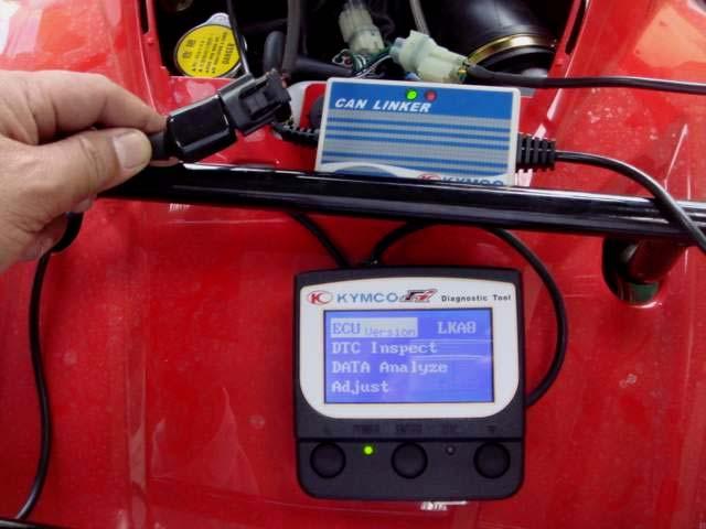
31 MXU 500I DX ATV FI DIAGNOSTIC TOOL OPERATION INSTRUCTIONS 3620A-LEB2-E00(ENGLISH VERSION) version:v

32 31 1. FI DIAGNOSTIC TOOL This tool is developed by KYMCO and for KYMCO vehicle only. Please refer to the specification when serving this vehicle. This tool is without battery inside. The power is provided from vehicle. This software can be updated with computer for new model through the USB cable. The power required of tool is connected with 12V battery. For connection, please connect this tool with the connector of ECU. It s available when turning on the ignition switch. The function includes ECU version, model name, data analysis. - ECU version: includes model name, ECU number, identifications number and software version. - Failure codes: DTC reading, DTC clearing and troubleshooting. - Data analysis: For ECU s software inspection. - Adjust : The adjust function setting is not allowed ECU Version DTC Inspect DATA Analyze Adjust Model No. UP Button Down Button Power indicator Enter or Exit DTC indicator(failure codes) 5-31

33 MXU 500I DX 2. DTC INSPECTION PROCEDURE Showing four functions on the screen when switching on power. LKA8 is for MXU500i A). ECU version: Including of model name, ECU number, identifications number and software version. Press the Enter button Press the " Enter " button LKA8 is for MXU500i 5-32
34 33 B). Press the " Down " button and then turn to the first page. C). Press the " Enter " button to check the DTC failure code 5-33

.")


35 MXU 500I DX D). Press the " Enter " button E). Press the " Enter " button F). Display what's DTC number on this DTC-List. Press the " Enter " button and then turn to the previous page 5-34

. Press the \" UP \" button")
36 G). Press the " UP " button H). Press the " Enter " button and then turn to the previous page. I). Press the " UP " button 5-35

37 J). Press the " Enter " button and then turn to the first page. 5-36
.")

38 3. DTC CLEAR PROCEDURE A). Check the DTC B). Press the " Enter " button C). Choose " Load DTC " Press the " Down " button 5-37

.")

39 D). Press the " Enter " button and the indicator is lighting. E). Clearing DTC completed if the indicator is off. 5-38
.")
.")

40 4. DATA ANALYSIS PROCEDURE A). Press the " Down " twice B). Choose Data Analyze Press the " Enter " button to enter page 01 C). Down-page 01 The measure figures including of Engine speed, Battery voltage and Engine speed. Press the " Down " button to enter page
.")


41 D). Down-page 02 The measure figures including of TPS position, TPI idle adapted and ISC step. Press the Down button to enter page 03. E). Down-page 03 The measure figures including of engine temperature,air temperature and intake pressure.press the Down button to enter page 04. F). Down-page 04 The measure figures including of atmosphere temperature, fuel injector interval and ignition advance. Press the Down button to enter page


.")
42 G). Down-page 05 The measure figures including of gear position and gear ratio. Press the Down button to enter page 06. H). Down-page 06 The measure figures including of rollover voltage(the function setting is not allowed). Press the Down button to enter page 07. I). Down-page 07 The measure figures including of ECU counter. J). Press the " UP " to the previous page. 5-42
General Service Information
 KYMCO MXU 500i/700i Repair Manual Fuel System MXU 700i 3.Fuel System MXU 700i This chapter covers the location and servicing of the fuel system components for the fuel injected KYMCO MXU 700i models. 1.Airbox...
Fuel Injection System
 7. Fuel Injection System XCITING 400i Fuel Injection System This chapter covers the location and servicing of the fuel system components for the KYMCO XCITING 400i. Air box... 7-2~7-5 Fuel Tank... 7-6~7-10
AFI (AUTOMATIC FUEL INJECTION)
") 14 AFI (AUTOMATIC FUEL INJECTION) SERVICE INFORMATION----------------------------------------------14-1 SYSTEM DIAGRAM -----------------------------------------------------14-4 SYSTEM LOCATION ----------------------------------------------------14-5
14 AFI (AUTOMATIC FUEL INJECTION) SERVICE INFORMATION----------------------------------------------14-1 SYSTEM DIAGRAM -----------------------------------------------------14-4 SYSTEM LOCATION ----------------------------------------------------14-5
5. FUEL SYSTEM 5-0 FUEL SYSTEM MXU 250R/300R
 5 FUEL SYSTEM 5 SERVICE INFORMATION------------------------------------------------ 5-2 TROUBLESHOOTING----------------------------------------------------- 5-3 FUEL TANK -----------------------------------------------------------------
4. FUEL SYSTEM CK 1 4-0
 4 4 4-0 SERVICE INFORMATION... 4-1 FLOAT LEVEL INSPECTION... 4-5 TROUBLESHOOTING... 4-2 CARBURETOR INSTALLATION... 4-6 THROTTLE VALVE DISASSEMBLY... 4-3 THROTTLE VALVE ASSEMBLY... 4-6 CARBURETOR REMOVAL...
7. FUEL SYSTEM ('04 - '05)
") 7. FUEL SYSTEM ('04 - '05) SYSTEM COMPONENTS 7-2 CARBURETOR DISASSEMBLY 7-81 SERVICE INFORMATION 7-3 CARBURETOR ASSEMBLY 7-14 TROUBLESHOOTING 7-4 CARBURETOR INSTALLATION 7-21 AIR CLEANER HOUSING 7-5 PILOT
7. FUEL SYSTEM ('04 - '05) SYSTEM COMPONENTS 7-2 CARBURETOR DISASSEMBLY 7-81 SERVICE INFORMATION 7-3 CARBURETOR ASSEMBLY 7-14 TROUBLESHOOTING 7-4 CARBURETOR INSTALLATION 7-21 AIR CLEANER HOUSING 7-5 PILOT
5. FUEL SYSTEM 5-0 FUEL SYSTEM UXV 500
 5 FUEL SYSTEM 5 SERVICE INFORMATION------------------------------------------------ 5-02 TROUBLESHOOTING----------------------------------------------------- 5-03 FUEL TANK -----------------------------------------------------------------
4. FUEL SYSTEM 4-0 FUEL SYSTEM NEXXON 50
 4 FUEL SYSTEM SERVICE INFORMATION ------------------------------------------------ 4-2 TROUBLESHOOTING----------------------------------------------------- 4-3 AIR CLEANER REMOVAL -----------------------------------------------
Do not bend or twist the control cable. Damaged control cable will not operate smoothly and may stick or bind.
 XL200 4. FUEL SYSTEM SERVICE INFORMATION 4-1 TROUBLESHOOTING 4-2 CARBURETOR 4-3 PILOT SCREW ADJUSTMENT 4-14 ACCELERATOR PUMP ADJUSTMENT 4-15 AIR CLEANER HOUSING 4-15 FUEL TANK 4-16 SERVICE INFORMATION
4-2. FUEL INJECTION SYSTEM
 Fuel Injection System Components..1 Precautions in servicing..2 General..2 Connector/coupler...3 Fuse...3 ECU/various sensors.. 3 Electrical circuit inspection procedure. 4 Parts location...8 Wiring diagram....9
5. FUEL SYSTEM FUEL SYSTEM 5-0
 5 FUEL SYSTEM 5-0 SERVICE INFORMATION GENERAL INSTRUCTIONS SERVICE INFORMATION...5-1 CARBURETOR INSTALLATION...5-9 TROUBLESHOOTING...5-1 PILOT SCREW ADJUSTMENT...5-10 CARBURETOR REMOVAL...5-2 AUTO BYSTARTER...5-3
CARBURETOR SERVICE INFORMATION TROUBLESHOOTING THROTTLE VALVE DISASSEMBLY THROTTLE VALVE INSTALLATION...
 11 CARBURETOR SERVICE INFORMATION... 11-2 TROUBLESHOOTING... 11-2 THROTTLE VALVE DISASSEMBLY... 11-3 THROTTLE VALVE INSTALLATION... 11-4 CARBURETOR REMOVAL... 11-5 AUTO BYSTARTER... 11-6 FLOAT CHAMBER...
G - TESTS W/CODES - 2.2L
 G - TESTS W/CODES - 2.2L 1994 Toyota Celica 1994 ENGINE PERFORMANCE Toyota 2.2L Self-Diagnostics Celica INTRODUCTION If no faults were found while performing F - BASIC TESTING, proceed with self-diagnostics.
EFI - Elektronisk bränsleinsprutning
 TGB ATV EFI - Elektronisk bränsleinsprutning Komplement till ordinarie verkstadshandbok för förgasarmotor PARTS LOCATION 1 ECU 10 Ignition Coil 2 Tilt Switch 11 Throttle Position Sensor 3 Injector 12 Idle
12. CARBURETOR 12-0 CARBURETOR VITALITY 50
 12 12 CARBURETOR SERVICE INFORMATION (2-STROKE)... 12-2 SERVICE INFORMATION (4-STROKE)... 12-3 THROTTLE VALVE (2-STROKE)... 12-5 CARBURETOR (2-STROKE)... 12-7 AIR SCREW ADJUSTMENT (2-STROKE)... 12-13 REED
11. CARBURETOR 11-0 CARBURETOR ZX / SCOUT 50
 11 CARBURETOR SERVICE INFORMATION... 11-2 TROUBLESHOOTING... 11-2 THROTTLE VALVE DISASSEMBLY... 11-3 THROTTLE VALVE INSTALLATION... 11-4 CARBURETOR REMOVAL... 11-5 AUTO BYSTARTER... 11-6 FLOAT CHAMBER...
FUEL SYSTEM/CARBURETOR/FUEL PUMP
 13 FUEL SYSTEM/CARBURETOR/FUEL PUMP FUEL SYSTEM-------------------------------------------------------------------------------------13-1 SCHEMATIC DRAWING-------------------------------------------------------------------------13-2
MULTIPOINT FUEL INJECTION (MPI) <4G9>
 <4G9>") MULTIPOINT FUEL INJECTION (MPI) 13C-1 MULTIPOINT FUEL INJECTION (MPI) CONTENTS GENERAL................................. 2 Outline of Changes............................ 2 GENERAL INFORMATION...................
MULTIPOINT FUEL INJECTION (MPI) 13C-1 MULTIPOINT FUEL INJECTION (MPI) CONTENTS GENERAL................................. 2 Outline of Changes............................ 2 GENERAL INFORMATION...................
12. CARBURETOR/FUEL PUMP
 12 CARBURETOR/FUEL PUMP SERVICE INFORMATION... 12-2 TROUBLESHOOTING... 12-2 THROTTLE VALVE DISASSEMBLY... 12-3 THROTTLE VALVE INSTALLATION... 12-4 CARBURETOR REMOVAL... 12-5 AUTO BYSTARTER... 12-6 FLOAT
1998 ENGINE PERFORMANCE. General Motors Corp. - Basic Diagnostic Procedures - 5.7L
 INTRODUCTION 1998 ENGINE PERFORMANCE General Motors Corp. - Basic Diagnostic Procedures - 5.7L The following diagnostic steps will help prevent overlooking a simple problem. This is also where to begin
DI 3 ENGINE DIAGNOSTICS DI00H 22 PRE CHECK
 PRECHECK DI3 DI00H22 1. DIAGNOSIS SYSTEM (a) Description When troubleshooting OBD II vehicles, the only difference from the usual troubleshooting procedure is that you connect to the vehicle the OBD II
2002 ENGINE PERFORMANCE. Self-Diagnostics - RAV4. Before performing testing procedures, check for any related Technical Service Bulletins (TSBs).
.") 2002 ENGINE PERFORMANCE Self-Diagnostics - RAV4 INTRODUCTION NOTE: Before performing testing procedures, check for any related Technical Service Bulletins (TSBs). To properly diagnosis and repair this
2002 ENGINE PERFORMANCE Self-Diagnostics - RAV4 INTRODUCTION NOTE: Before performing testing procedures, check for any related Technical Service Bulletins (TSBs). To properly diagnosis and repair this
H - TESTS W/O CODES Volvo 960 INTRODUCTION SYMPTOMS SYMPTOM DIAGNOSIS ENGINE PERFORMANCE Volvo Trouble Shooting - No Codes
 H - TESTS W/O CODES 1994 Volvo 960 1994 ENGINE PERFORMANCE Volvo Trouble Shooting - No Codes Volvo; 850, 940, 960 INTRODUCTION Before diagnosing symptoms or intermittent faults, perform steps in appropriate
6. FUEL SYSTEM 6-1 FUEL TANK COMPONENT LOCATION 6-2 INTAKE PIPE SERVICE INFORMATION 6-3 CARBURETOR TROUBLESHOOTlNG 6-4
 6... COMPONENT LOCATION 6-2 SERVICE INFORMATION 6-3 TROUBLESHOOTlNG 6-4 AIR CLEANER HOUSING 6-5 FUEL TANK...... 6-5 INTAKE PIPE...... 6-6 CARBURETOR.............. 6-6 AIR SCREW ADJUSTMENT 6-15 6-1 COMPONENT
13. FUEL SYSTEM/CARBURETOR/
 13 FUEL SYSTEM/CARBURETOR/FUEL PUMP FUEL SYSTEM --------------------------------------------------------- 13-1 SCHEMATIC DRAWING ---------------------------------------------- 13-2 OPERATION OF CARBURETOR
DI 3 ENGINE DIAGNOSTICS DI PRE CHECK
 FI0534 PRECHECK DI3 DI09603 1. DIAGNOSIS SYSTEM (a) Description When troubleshooting OBD II vehicles, the only difference from the usual troubleshooting procedure is that you connect to the vehicle the
H - TESTS W/O CODES INTRODUCTION SYMPTOMS
 H - TESTS W/O CODES 1995 Volvo 850 1995 ENGINE PERFORMANCE Volvo - Trouble Shooting - No Codes 850 INTRODUCTION Before diagnosing symptoms or intermittent faults, perform steps in the F - BASIC TESTING
DTC P0171 SYSTEM TOO LEAN (BANK 1) DTC P0174 SYSTEM TOO LEAN (BANK 2)
 DTC P0174 SYSTEM TOO LEAN (BANK 2)") 05498 DIAGNOSTICS DTC P0171 SYSTEM TOO LEAN (BANK 1) 05EXR06 DTC P0172 SYSTEM TOO RICH (BANK 1) DTC P0174 SYSTEM TOO LEAN (BANK 2) DTC P0175 SYSTEM TOO RICH (BANK 2) CIRCUIT DESCRIPTION The fuel trim is
05498 DIAGNOSTICS DTC P0171 SYSTEM TOO LEAN (BANK 1) 05EXR06 DTC P0172 SYSTEM TOO RICH (BANK 1) DTC P0174 SYSTEM TOO LEAN (BANK 2) DTC P0175 SYSTEM TOO RICH (BANK 2) CIRCUIT DESCRIPTION The fuel trim is
19. IGNITION SYSTEM 19-1 SYSTEM DIAGRAM 19-2 IGNITION SYSTEM INSPECTION 19-5 SERVICE INFORMATION 19-3 CKP SENSOR 19-7 TROUBLESHOOTING 19-4
 19. IGNITION SYSTEM SYSTEM DIAGRAM 19-2 SERVICE INFORMATION 19-3 TROUBLESHOOTING 19-4 IGNITION SYSTEM INSPECTION 19-5 CKP SENSOR 19-7 IGNITION TIMING 19-8 19 19-1 IGNITION SYSTEM IGNITION SYSTEM SYSTEM
FUEL SYSTEM CIRCUIT D'ESSENCE KRAFTSTOFFSYSTEM
 CIRCUIT D'ESSENCE KRAFTSTOFFSYSTEM 41 FUEL SYSTEM SERVICE INFORMATION TROUBLESHOOTING FUEL TANK AIR CLEANER CARBURETOR REMOVAL VACUUM CHAMBER FLOAT CHAMBER 4-1 PILOT SCREW 4-2 CARBURETOR SEPARATION 4-3
Instruction Manual for DOCTOR API Yamaha Diagnostic Tool
 Instruction Manual for DOCTOR API Yamaha Diagnostic Tool APITech Company www.apitechonline.com Facebook.com/apitechonline Tel.02-948-8680 Fax.02-948-8980 1 Content Page 1. Product Package 3 2. Product
F - BASIC TESTING Toyota Celica INTRODUCTION PRELIMINARY INSPECTION & ADJUSTMENTS VISUAL INSPECTION MECHANICAL INSPECTION
 F - BASIC TESTING 1994 Toyota Celica 1994 ENGINE PERFORMANCE Toyota 4-Cylinder Basic Diagnostic Procedures Celica INTRODUCTION The following diagnostic steps will help prevent overlooking a simple problem.
FUEL SYSTEM PRECAUTION FU 1
 2GR-FE EL EL SYSTEM EL SYSTEM PRECAUTION 1 1. EXPRESSIONS OF IGNITION SWITCH (a) The type of the ignition switch used on this model differs according to the specifications of the vehicle. The expressions
HOW TO USE THIS MANUAL
 HOW TO USE THIS MANUAL TO LOCATE WHAT YOU ARE LOOKING FOR : 1. The text of this manual is divided into sections. 2.As the title of these sections is listed on the previous page as GROUP INDEX, select the
DTC P0341 Camshaft Position (CMP) Sensor Performance
 Sensor Performance") Page 1 of 5 1999 Buick Century Century, Regal VIN W Service Manual Document ID: 345654 DTC P0341 Camshaft Position (CMP) Sensor Performance Circuit Description During cranking, the Ignition Control Module
Page 1 of 5 1999 Buick Century Century, Regal VIN W Service Manual Document ID: 345654 DTC P0341 Camshaft Position (CMP) Sensor Performance Circuit Description During cranking, the Ignition Control Module
IGNITION SYSTEM ON VEHICLE INSPECTION NOTICE:
 SYSTEM ONVEHICLE INSPECTION NOTICE: SPARK TEST NO CHECK CONNECTION OF COIL, IGNITER AND DISTRIBUTOR CONNECTOR OK CHECK RESISTANCE OF HIGHTENSION CORD (See step 2) Maximum resistance: 25 kω per cord OK
FUEL 13-1 CONTENTS MULTIPOINT INJECTION (MPI)... 2 GENERAL INFORMATION... 2 SERVICE SPECIFICATIONS... 3 SEALANT... 3 SPECIAL TOOLS...
... 2 GENERAL INFORMATION... 2 SERVICE SPECIFICATIONS... 3 SEALANT... 3 SPECIAL TOOLS...") 13-1 FUEL CONTENTS MULTIPOINT INJECTION (MPI)....... 2 GENERAL INFORMATION................ 2 SERVICE SPECIFICATIONS.............. 3 SEALANT............................... 3 SPECIAL TOOLS........................
13-1 FUEL CONTENTS MULTIPOINT INJECTION (MPI)....... 2 GENERAL INFORMATION................ 2 SERVICE SPECIFICATIONS.............. 3 SEALANT............................... 3 SPECIAL TOOLS........................
FUEL INJECTION SYSTEM - MULTI-POINT
 FUEL INJECTION SYSTEM - MULTI-POINT 1988 Jeep Cherokee 1988 Electronic Fuel Injection JEEP MULTI-POINT 4.0L Cherokee, Comanche, Wagoneer DESCRIPTION The Multi-Point Electronic Fuel Injection (EFI) system
DTC P0300 Random/Multiple Cylinder Misfire Detected
 DI60 DI5DI03 DTC P0300 Random/Multiple Cylinder Misfire Detected DTC P0301 Cylinder 1 Misfire Detected DTC P0302 Cylinder 2 Misfire Detected DTC P0303 Cylinder 3 Misfire Detected DTC P0304 Cylinder 4 Misfire
3. Engine XCITING 400i. This chapter covers the location and servicing of the engine components for the KYMCO Xciting 400i.
 3. Engine XCITING 400i Engine This chapter covers the location and servicing of the engine components for the KYMCO Xciting 400i. Engine Removal... 3-4~3-12 Cylinder Head Cover... 3-13~3-17 Camshaft...
FUEL 13-1 CONTENTS MULTIPOINT INJECTION (MPI)... 2 FUEL SUPPLY ON-VEHICLE SERVICE GENERAL SERVICE SPECIFICATIONS... 4 SEALANT...
... 2 FUEL SUPPLY ON-VEHICLE SERVICE GENERAL SERVICE SPECIFICATIONS... 4 SEALANT...") 13-1 FUEL CONTENTS MULTIPOINT INJECTION (MPI)....... 2 GENERAL............................... 2 Outline of Change......................... 2 SERVICE SPECIFICATIONS.............. 4 SEALANT...............................
13-1 FUEL CONTENTS MULTIPOINT INJECTION (MPI)....... 2 GENERAL............................... 2 Outline of Change......................... 2 SERVICE SPECIFICATIONS.............. 4 SEALANT...............................
IGNITION SYSTEM IG-17 IG-21
 IGNITION SYSTEM Page PRECAUTIONS... IG-2 TROUBLESHOOTING... IG-3 IGNITION SYSTEM CIRCUIT... IG-4 ON-VEHICLE INSPECTION (7M-GE)... IG-5 ON-VEHICLE INSPECTION (7M-GTE)... IG-10 DISTRIBUTOR (7M-GE)... CAM
20. ELECTRICAL ('04 - '05)
") 20. ELECTRICAL ('04 - '05) COMPONENT LOCATION 20-2 HEADLIGHT 20-16 SERVICE INFORMATION 20-3 BRAKE/TAILLIGHT 20-18 TROUBLESHOOTING 20-5 IGNITION SWITCH 20-18 GENERATING SYSTEM 20-6 HANDLEBAR SWITCH- 20-19
20. ELECTRICAL ('04 - '05) COMPONENT LOCATION 20-2 HEADLIGHT 20-16 SERVICE INFORMATION 20-3 BRAKE/TAILLIGHT 20-18 TROUBLESHOOTING 20-5 IGNITION SWITCH 20-18 GENERATING SYSTEM 20-6 HANDLEBAR SWITCH- 20-19
F - BASIC TESTING Article Text 1992 Dodge Colt For a a a a a Copyright 1998 Mitchell Repair Information Company, LLC Saturday, April 27, :48PM
 Article Text ARTICLE BEGINNING 1992 ENGINE PERFORMANCE Chrysler Motors/Mitsubishi Basic Diagnostic Procedures Chrysler Motors: Colt, Colt 200, Summit Mitsubishi: Mirage INTRODUCTION The following diagnostic
CHAPTER 4 ELECTRONIC FUEL INJECTION
 CHAPTER ELECTRONIC FUEL INJECTION GENERAL INFORMATION.................................................2 SPECIAL TOOLS........................................................2 EFI SERVICE NOTES....................................................
Powertrain DTC Summaries EOBD
 Powertrain DTC Summaries Quick Reference Diagnostic Guide Jaguar X-TYPE 2.0 L 2002.25 Model Year Refer to page 2 for important information regarding the use of Powertrain DTC Summaries. Jaguar X-TYPE 2.0
DTC P0102 Mass Air Flow (MAF) Sensor Circuit Low Frequency
 Sensor Circuit Low Frequency") Page 1 of 5 1997 Pontiac Grand Prix Grand Prix (VIN W) Service Manual Engine Engine Controls - 3.8L Diagnostic Information and Procedures Document ID: 106986 DTC P0102 Mass Air Flow (MAF) Sensor Circuit
Page 1 of 5 1997 Pontiac Grand Prix Grand Prix (VIN W) Service Manual Engine Engine Controls - 3.8L Diagnostic Information and Procedures Document ID: 106986 DTC P0102 Mass Air Flow (MAF) Sensor Circuit
DTC P0172 Fuel Trim System Rich
 Page 1 of 6 1997 Chevrolet Cavalier Cavalier, Sunfire (VIN J) Service Manual Document ID: 47788 DTC P0172 Fuel Trim System Rich System Description A Closed Loop air/fuel metering system is used to provide
GL1800 FI "Fault Indicator" Dashboard Codes
 GL1800 FI "Fault Indicator" Dashboard Codes If FI (Fault Indicator) light comes on pull over but DO NOT shut bike off. Put in neutral and put side stand down, RPM s below 1500. This signals the ECM to
2002 Buick Rendezvous - AWD
 2002 Buick Rendezvous - AWD DTC P0410 Description The control module activates the secondary air injection (AIR) system by grounding both the pump relay and the vacuum control solenoid control circuits.
ON-VEHICLE INSPECTION
 Last Modified: 4-26-2007 Service Category: Engine/Hybrid System 1.6 G Section: Engine Mechanical Model Year: 2007 Model: 4Runner Doc ID: RM0000017L8004X Title: 1GR-FE ENGINE MECHANICAL: ENGINE: ON-VEHICLE
F - BASIC TESTING Volvo 850 INTRODUCTION PRELIMINARY INSPECTION & ADJUSTMENTS VISUAL INSPECTION MECHANICAL INSPECTION
 F - BASIC TESTING 1995 Volvo 850 1995 ENGINE PERFORMANCE Volvo - Basic Diagnostic Procedures 850 INTRODUCTION NOTE: In this article, Engine Control Module (ECM) may also be referred to as Engine Control
Typical Install Instructions
 Typical Install Instructions Read & understand all steps of these instructions before beginning this installation. WEBER Conversion Kit, VW T-1/2, up to 1835cc 32 / 36 DFEV Weber Carburetor These instructions
22 ANTI-LOCK BRAKE SYSTEM (ABS)
") 21 ANTI-LOCK BRAKE SYSTEM (ABS) ABS Indicator Light---------------------------------------- --------- 22 01 22 ABS Introduction-------------------------------------------- --------- 22 02 ABS Parts Location
21 ANTI-LOCK BRAKE SYSTEM (ABS) ABS Indicator Light---------------------------------------- --------- 22 01 22 ABS Introduction-------------------------------------------- --------- 22 02 ABS Parts Location
Engine Cranks But Does Not Run
 Page 1 of 5 2000 GMC Truck GMC K Sierra - 4WD Sierra, Silverado, Suburban, Tahoe, Yukon (VIN C/K) Service Manual Engine Engine Controls - 4.8L, 5.3L, and 6.0L Diagnostic Information and Procedures Engine
7649A FUEL INJECTOR CLEANING SPECIALTY TOOLS USER MANUAL & REPLACEMENT PARTS LIST
 7649A FUEL INJECTOR CLEANING SPECIALTY TOOLS USER MANUAL & REPLACEMENT PARTS LIST Safety Precautions WARNING: The following safety precautions must be carefully observed to reduce the risk of fire and
5-2 FUEL SYSTEM AND THROTTLE BODY FUEL SYSTEM FUEL DELIVERY SYSTEM The fuel delivery system consists of the fuel tank, fuel pump, fuel filters, fuel f
 FUEL SYSTEM AND THROTTLE BODY 5-1 FUEL SYSTEM AND THROTTLE BODY I CONTENTS FUEL SYSTEM 5-2 FUEL DELIVERY SYSTEM 5-2 FUEL PUMP 5-3 FUEL PRESSURE REGULATOR 5-4 FUEL INJECTOR 5-4 FUEL PUMP CONTROL SYSTEM
Cylinder Head Setting Bolt Tightening Adaptor Injection Measuring Tool Set EFI Fuel Pressure Gauge
 SFI SYSTEM (2JZGE) EG187 SFI SYSTEM (2JZGE) PREPARATION SST (SPECIAL SERVICE TOOLS) 0920576030 Cylinder Head Setting Bolt Tightening Adaptor ECT sensor 0926841045 Injection Measuring Tool Set (0926841070)
TO INDEX IGNITION SYSTEM
 TO INDEX IGNITION SYSTEM IG IGNITION SYSTEM CIRCUIT... IG 2 SPARK TEST... IG 4 SPARK PLUG... IG 4 POWER SUPPLY... IG 5 CRANK ANGLE SENSOR... IG 7 CAM ANGLE SENSOR... IG 8 EFI ECU... IG 8 IGNITION TIMING...
Powertrain DTC Summaries EOBD
 Powertrain DTC Summaries Quick Reference Diagnostic Guide Jaguar S-TYPE V6, V8 N/A and V8 SC 2002.5 Model Year Refer to pages 2 9 for important information regarding the use of Powertrain DTC Summaries.
DTC P1415 Secondary Air Injection (AIR) System Bank 1
 System Bank 1") Page 1 of 5 2000 GMC Truck GMC K Sierra - 4WD Sierra, Silverado, Suburban, Tahoe, Yukon (VIN C/K) Service Manual Document ID: 546887 DTC P1415 Secondary Air Injection (AIR) System Bank 1 Circuit Description
Page 1 of 5 2000 GMC Truck GMC K Sierra - 4WD Sierra, Silverado, Suburban, Tahoe, Yukon (VIN C/K) Service Manual Document ID: 546887 DTC P1415 Secondary Air Injection (AIR) System Bank 1 Circuit Description
ELECTRONIC FUEL INJECTION
 Table of Contents ELECTRONIC FUEL INJECTION Section 3B - Troubleshooting and Diagnostics TROUBLESHOOTING AND DIAGNOSTICS Specifications........................... 3B-1 Special Tools...........................
DTC P0341 Camshaft Position (CMP) Sensor Performance
 Sensor Performance") Page 1 of 7 1997 Buick Riviera Aurora, Riviera (VIN G) Service Manual Document ID: 53298 DTC P0341 Camshaft Position (CMP) Sensor Performance Circuit Description The camshaft position PCM input is produced
Page 1 of 7 1997 Buick Riviera Aurora, Riviera (VIN G) Service Manual Document ID: 53298 DTC P0341 Camshaft Position (CMP) Sensor Performance Circuit Description The camshaft position PCM input is produced
Idle Air Control (IAC) System Diagnosis
 System Diagnosis") 2001 Oldsmobile Alero Idle Air Control (IAC) System Diagnosis Circuit Description The idle air control (IAC) valve is located in the throttle body. It consists of a movable pintle, driven by a gear attached
2001 Oldsmobile Alero Idle Air Control (IAC) System Diagnosis Circuit Description The idle air control (IAC) valve is located in the throttle body. It consists of a movable pintle, driven by a gear attached
IGNITION SYSTEM ON-VEHICLE INSPECTION NOTICE:
 ONVEHICLE INSPECTION SPARK TEST NO CHECK CONNECTION OF COIL CONNECTOR CHANGE IT TO NORMAL COIL (WITH IGNITER) AND PERFORM SPARK TEST AGAIN NO CHECK POWER SUPPLY TO COIL (WITH IGNITER) 1. Turn ignition
DTC P0300 Random / Multiple Cylinder Misfire Detected. DTC P0301 Cylinder 1 Misfire Detected. DTC P0302 Cylinder 2 Misfire Detected
 1GR-FE EINE CONTROL SYSTEM SFI SYSTEM 169 DTC P0300 Random / Multiple Cylinder Misfire Detected DTC P0301 Cylinder 1 Misfire Detected DTC P0302 Cylinder 2 Misfire Detected DTC P0303 Cylinder 3 Misfire
DTC P0300 Random/Multiple Cylinder Misfire Detected
 EINE (5VZFE) DI301 DIB1V01 DTC P0300 Random/Multiple Cylinder Misfire Detected DTC P0301 Cylinder 1 Misfire Detected DTC P0302 Cylinder 2 Misfire Detected DTC P0303 Cylinder 3 Misfire Detected DTC P0304
Alternative Fuel Engine Control Unit
 1999 Chevrolet/Geo Cavalier (CNG) Alternative Fuel Engine Control Unit Table 1: AF ECU Function Parameters The (AF ECU) controls alternative fuel engine operation. The control unit monitors various engine
DTC P0300 RANDOM/MULTIPLE CYLINDER MISFIRE DETECTED DTC P0301 CYLINDER 1 MISFIRE DETECTED DTC P0302 CYLINDER 2 MISFIRE DETECTED
 DTC P0300 RANDOM/MULTIPLE CYLINDER MISFIRE DETECTED 0539 059VJ09 DTC P030 CYLINDER MISFIRE DETECTED DTC P0302 CYLINDER 2 MISFIRE DETECTED DTC P0303 CYLINDER 3 MISFIRE DETECTED DTC P0304 CYLINDER 4 MISFIRE
DTC P0300 Random/Multiple Cylinder Misfire Detected
 DI56 EINE (2RZFE, 3RZFE) DI8ZU01 DTC P0300 Random/Multiple Cylinder Misfire Detected DTC P0301 Cylinder 1 Misfire Detected DTC P0302 Cylinder 2 Misfire Detected DTC P0303 Cylinder 3 Misfire Detected DTC
Idle Air Control (IAC) System Diagnosis
 System Diagnosis") 2000 GMC Truck GMC K Sierra - 4WD Idle Air Control (IAC) System Diagnosis Circuit Description The vehicle control module (VCM) controls idle RPM with the idle air control (IAC) valve. To increase idle
2000 GMC Truck GMC K Sierra - 4WD Idle Air Control (IAC) System Diagnosis Circuit Description The vehicle control module (VCM) controls idle RPM with the idle air control (IAC) valve. To increase idle
DTC P0300 Random / Multiple Cylinder Misfire Detected
 162 DTC P0300 Random / Multiple Cylinder Misfire Detected DTC P0301 Cylinder 1 Misfire Detected DTC P0302 Cylinder 2 Misfire Detected DTC P0303 Cylinder 3 Misfire Detected DTC P0304 Cylinder 4 Misfire
F - BASIC TESTING Infiniti G20 INTRODUCTION PRELIMINARY INSPECTION & ADJUSTMENTS VISUAL INSPECTION MECHANICAL INSPECTION
 F - BASIC TESTING 1992 Infiniti G20 1992 ENGINE PERFORMANCE Infiniti Basic Diagnostic Procedures G20, M30, Q45 INTRODUCTION The following diagnostic steps will help prevent overlooking a simple problem.
WEBER CARBURETOR TROUBLESHOOTING GUIDE
 This guide is to help pinpoint problems by diagnosing engine symptoms associated with specific vehicle operating conditions. The chart will guide you step by step to help correct these problems. For successful
1ZZ-FE ENGINE CONTROL SYSTEM SFI SYSTEM. DTC P0300 Random / Multiple Cylinder Misfire Detected ECM
 164 DTC P0300 Random / Multiple Cylinder Misfire Detected DTC P0301 Cylinder 1 Misfire Detected DTC P0302 Cylinder 2 Misfire Detected DTC P0303 Cylinder 3 Misfire Detected DTC P0304 Cylinder 4 Misfire
Stop Lamp Switch. STP or BRK. Stop Lamps
 WORKSHEET 2 1 Position/Mode Switches and Circuits (Instructor Copy) Vehicle Year/Prod. Date Engine Transmission Technician Objectives With this worksheet, you will learn to test position/mode circuits
Powertrain DTC Summaries OBD II
 Powertrain DTC Summaries Quick Reference Diagnostic Guide Jaguar X-TYPE 2.5L and 3.0L 2002 Model Year Revised January, 2002: P0706, P0731, P0732, P0733, P0734, P0735, P0740, P1780 POSSIBLE CAUSES Revised
On Board Diagnostics II A PCED
 1998 PCED On Board Diagnostics II A SECTION 5A: Pinpoint Tests HA: Natural Gas Fuel Control HA: Introduction HA30 DTCS P05, P0141, P0155 AND P0161: HO2S HEATER SIGNAL CIRCUIT IS OPEN, SHORTED TO GROUND,
18. IGNITION SYSTEM 18-1 SYSTEM DIAGRAM 18-2 IGNITION SYSTEM INSPECTION 18-5 SERVICE INFORMATION 18-3 IGNITION COIL 18-8 TROUBLESHOOTING 18-4
 18. IGNITION SYSTEM SYSTEM DIAGRAM 18-2 SERVICE INFORMATION 18-3 TROUBLESHOOTING 18-4 IGNITION SYSTEM INSPECTION 18-5 IGNITION COIL 18-8 IGNITION TIMING 18-8 18 18-1 IGNITION SYSTEM SYSTEM DIAGRAM IGNITION
Idle Air Control (IAC) System Diagnosis
 System Diagnosis") Page 1 of 6 2002 Chevrolet Tahoe - 4WD Avalanche, Escalade, Suburban, Tahoe, Yukon VIN C/K Service Manual Engine Engine Controls - 4.8L, 5.3L, and 6.0L Diagnostic Information and Procedures Document ID:
Page 1 of 6 2002 Chevrolet Tahoe - 4WD Avalanche, Escalade, Suburban, Tahoe, Yukon VIN C/K Service Manual Engine Engine Controls - 4.8L, 5.3L, and 6.0L Diagnostic Information and Procedures Document ID:
BODY ELECTRICAL SYSTEM
 BODY ELECTRICAL SYSTEM 8-1 SECTION 8 BODY ELECTRICAL SYSTEM WARNING: For vehicles equipped with Supplemental Restraint (Air Bag) System: Service on and around the air bag system components or wiring must
IG 1 2GR-FE IGNITION IGNITION SYSTEM IGNITION SYSTEM ECM ENGINE ROOM R/B - IG2 FUSE - ST/AM FUSE IGNITION COIL NOISE FILTER NOISE FILTER A137458E01
 NITION SYSTEM ENGINE 2GR-FE PARTS LOCATION 2GR-FE NITION NITION SYSTEM 1 ECM ENGINE ROOM R/B - 2 FUSE NITION COIL - ST/AM FUSE NOISE FILTER NOISE FILTER A137458E01 2 2GR-FE NITION NITION SYSTEM SYSTEM
13A-1 FUEL CONTENTS MULTIPOINT FUEL INJECTION (MPI) FUEL SUPPLY... 13B
 FUEL SUPPLY... 13B") 13A-1 FUEL CONTENTS MULTIPOINT FUEL INJECTION (MPI)... 13A FUEL SUPPLY... 13B 13A-2 MULTIPOINT FUEL INJECTION (MPI) CONTENTS GENERAL INFORMATION... 3 SERVICE SPECIFICATIONS... 6 SEALANT... 6 SPECIAL TOOLS...
13A-1 FUEL CONTENTS MULTIPOINT FUEL INJECTION (MPI)... 13A FUEL SUPPLY... 13B 13A-2 MULTIPOINT FUEL INJECTION (MPI) CONTENTS GENERAL INFORMATION... 3 SERVICE SPECIFICATIONS... 6 SEALANT... 6 SPECIAL TOOLS...
1993 ENGINE PERFORMANCE Volkswagen Basic Diagnostic Procedures. Cabriolet, Corrado SLC, EuroVan, Fox, Golf, GTI, Jetta, Passat GL, Passat GLX
 Article Text ARTICLE BEGINNING 1993 ENGINE PERFORMANCE Volkswagen Basic Diagnostic Procedures Cabriolet, Corrado SLC, EuroVan, Fox, Golf, GTI, Jetta, Passat GL, Passat GLX INTRODUCTION The following diagnostic
Oregon Fuel Injection
 2001 2006 Dodge Mercedes - Freightliner Sprinter Diagnostics In order to do proper diagnostics you will need a scan tool and some special tools available from Mopar Special Tools http://mopar.snapon.com.
The engine control module (ECM) uses the following information to calculate an expected airflow rate.
 uses the following information to calculate an expected airflow rate.") DTC Descriptors DTC Mass Air Flow (MAF) sensor performance Circuit/System Description The engine control module (ECM) uses the following information to calculate an expected airflow rate. The throttle
DTC Descriptors DTC Mass Air Flow (MAF) sensor performance Circuit/System Description The engine control module (ECM) uses the following information to calculate an expected airflow rate. The throttle
IGNITION SYSTEM ON-VEHICLE INSPECTION
 ONVEHICLE INSPECTION IGNITION (5VZFE) and in these sentences express the temperature of the coils themselves. is from 10 C (14 F) to 50 C (122 F) and is from 50 C (122 F) to 100 C (212 F). 1. INSPECT IGNITOR
2UZ-FE ENGINE CONTROL SYSTEM SFI SYSTEM
 160 2UZ-FE EINE CONTROL SYSTEM SFI SYSTEM DTC P0171 System Too Lean (Bank 1) DTC P0172 System Too Rich (Bank 1) DTC P0174 System Too Lean (Bank 2) DTC P0175 System Too Rich (Bank 2) DCRIPTION The fuel
ENGINE AND EMISSION CONTROL
 17-1 GROUP 17 ENGINE AND EMISSION CONTROL CONTENTS ENGINE CONTROL.......... 17-3 GENERAL DESCRIPTION...... 17-3 ENGINE CONTROL SYSTEM DIAGNOSIS.................. 17-3 INTRODUCTION TO ENGINE CONTROL SYSTEM
H - TESTS W/O CODES Nissan 240SX INTRODUCTION TROUBLE SHOOTING SYMPTOMS DIAGNOSIS WILL NOT START
 H - TESTS W/O CODES 1990 Nissan 240SX 1990 ENGINE PERFORMANCE Trouble Shooting - No Codes Nissan; 240SX, Axxess, Maxima, Pathfinder, Pickup, Pulsar, Sentra, Van, INTRODUCTION Before diagnosing symptoms
1 of 2 9/4/ :27 AM
 Ford Mustang IAC IAB - Solving your idle problems http://www.muscularmustangs.com/iac.php 1 of 2 9/4/2010 10:27 AM Solving idle problems part 1 - Cleaning your IAC Does your idle rise and fall over and
DIAGNOSIS SYSTEM DESCRIPTION EG2 170
 EG2170 DIAGNOSIS SYSTEM DESCRIPTION The ECM contains a builtin self diagnosis system by which troubles with the engine signal network are detected and a malfunction indicator lamp on the combination meter
Miata - Workshop Manual - Engine
 Page 1 of 8 2003 - Miata - Workshop Manual - Engine NO.6 CRANKS NORMALLY BUT WILL NOT START 6 Cranks normally but will not start Starter cranks engine at normal speed but engine will not run. DESCRIPTION
Section 10 Chapter 7
 Section 10 Chapter 7 24 Valve, 8.3 Liter Engine Troubleshooting Symptoms Identification Note: All coding used in the 8.3 Liter and 9 Liter engine manuals are Cummins engine codes. These engine codes have
GROUP 17 CONTENTS WARNINGS REGARDING SERVICING OF SUPPLEMENTAL RESTRAINT SYSTEM (SRS) EQUIPPED VEHICLES
 EQUIPPED VEHICLES") 17-1 GROUP 17 CONTENTS ENGINE CONTROL 17-4 GENERAL DESCRIPTION 17-4 ENGINE CONTROL SYSTEM DIAGNOSIS 17-4 INTRODUCTION TO ENGINE CONTROL SYSTEM DIAGNOSIS 17-4 ENGINE CONTROL SYSTEM DIAGNOSTIC TROUBLESHOOTING
17-1 GROUP 17 CONTENTS ENGINE CONTROL 17-4 GENERAL DESCRIPTION 17-4 ENGINE CONTROL SYSTEM DIAGNOSIS 17-4 INTRODUCTION TO ENGINE CONTROL SYSTEM DIAGNOSIS 17-4 ENGINE CONTROL SYSTEM DIAGNOSTIC TROUBLESHOOTING
TROUBLESHOOTING FOR EFI ELECTRONIC CIRCUIT WITH VOLT/OHMMETER
 FI118 TROUBLESHOOTING FOR EFI ELECTRONIC CIRCUIT WITH VOLT/OHMMETER HINT: Because the following troubleshooting procedures are designed for inspection of each separate system, the actual troubleshooting
1 of 7 12/18/2016 9:15 PM
 1 of 7 12/18/2016 9:15 PM P0456-EVAP SYSTEM SMALL LEAK Special Tools: For a complete wiring diagram, refer to the Wiring Information. 2 of 7 12/18/2016 9:15 PM Theory of Operation 3 of 7 12/18/2016 9:15
SPN 106. Suspect Parameter Number (SPN) and Failure Mode Indicator (FMI) Description
 and Failure Mode Indicator (FMI) Description") SPN 106 Suspect Parameter Number (SPN) and Failure Mode Indicator (FMI) Description SPN FMI Description Possible Causes 106 3 MAP Sensor Signal Voltage High Open/high resistance in low reference circuit
SPN 106 Suspect Parameter Number (SPN) and Failure Mode Indicator (FMI) Description SPN FMI Description Possible Causes 106 3 MAP Sensor Signal Voltage High Open/high resistance in low reference circuit
PROBLEM SYMPTOMS TABLE
 3MZ-FE ENGINE CONTROL SYSTEM SFI SYSTEM 29 SFI SYSTEM PROBLEM SYMPTOMS TABLE Symptom Suspected area See page 1. Starter ST-8 Engine does not crank (Does not start) 2. ST relay ST-2 3. Park/neutral position
Document ID: General Motors Corporation. All rights reserved.
 Page 1 of 6 2005 Chevrolet TrailBlazer - 4WD Envoy, Rainier, TrailBlazer, Ascender (VIN S/T) Service Manual Document ID: 1489377 DTC P0053 or P0054 Circuit Description The heated oxygen sensor (HO2S) must