Instruction Manual for DOCTOR API Yamaha Diagnostic Tool
|
|
|
- Mitchell Bryan
- 5 years ago
- Views:
Transcription


1 Instruction Manual for DOCTOR API Yamaha Diagnostic Tool APITech Company Facebook.com/apitechonline Tel Fax
2 Content Page 1. Product Package 3 2. Product details and features for Yamaha Diagnostic Tool Product Technical Details Product Features Product Detail 5 3. Instruction for Diagnostic Tool Real Time Monitoring Analysis Problem Analysis Mode Function Analysis Mode CO Adjustment Real Time Monitoring Analysis CO Adjustment Detail DTC Error Connection Process Doctor API to the motorcycle Sample Using with Yamaha R Function Bootloader 32 2


3 3 Product Package 3.2 DOCTOR API Yamaha Diagnostic Tool 3.3 Instruction Manual 3.4 Sticker API TECH 1.3 Warranty 3
4 2. Product details and features for Yamaha Diagnostic Tool 2.1 Product technical details 1. Battery Voltage Voltage 2. Electricity consumes 0.5 ampere 3. Processing 32Bit ARM Cortex 4. Temperature 0-50 C 5. Dimension Width 10 cm. Length 11 cm. Height 4 cm. 6. Weight 0.3 KG 2.2 Product Feature - Workable with Yamaha motorcycles from 1-4 Cylinders - K-Line communication provided - LCD screen 16x4 character and computer screen readable - Fault codes provided - Historical fault codes provided - clearing fault codes provided - Dynamic data stream provided - Upgradable - Wireless (Bluetooth) provided - Android OS provided 4
5 2.3 Product detail No. 1 No 2 DOWN Button MODE ENTER No 3 UP Button No 4 LCD screen 16x4 character and computer screen readable No 5 K-Line communication provided 5
6 3 Diagnostic Tool Instruction 3.1. Real Time Monitoring The system will show processing as real time monitoring. The ECM in each Yamaha motorcycles are different in each model, the data will be different. The data that will be shown on the screen will depend on the models. 1. The Input Signal consisted of - RPM_DATA (Revolution Per Minute) - ENGINE_TEMP (ECT=Engine Coolant Temperature or EOT= Engine Oil Temperature) - INTAKE_AIR_TEMP ( Intake Air Temperature) - ATMOSP_PRESSURE_SENSOR (Atmosphere Pressure Sensor) - VEHICLE_SPEED (Vehicle Speed) - BATTERY - THRO_POSITION_SENSOR_VOLTAGE (Throttle Position Sensor Voltage) - LEAN_ANGLE_SENSOR (Lean Angle Sensor) - AFR # 1 ( O2_SENSOR_1 ) - AFR # 2 ( O2_SENSOR_2 ) - INTAKE_AIR_PRESSURE_SENSOR_1 (Intake Air Pressure Sensor #1) - INTAKE_AIR_PRESSURE_SENSOR_2 (Intake Air Pressure Sensor #2) - THRO_POSITION_SENSOR_ANGLE ( Throttle Position Angle Sensor) - ACCELERATOR_POSSION_SENSOR_ANGLE ( Acceleration Position Angle Sensor) - MODE - SWITCH_1 (Switch #1) - SWITCH_2 (Switch#2) - PRIMARY_SHEAVE_POSITION_SENSOR_VOLTAGE - I_SHIFT_POSITION 6
7 2.Output Control consisted of - INJECTION_DUTATION (Injection duration) - NITION_TIMING (Ignition Timing) - ISC_VALVE (Idle Speed Con YCC ( YCC_AT_MOTOR_DUTY ) 3.Internal ECM - ( GEAR_POSITION ) Position of Gear - ( FAULT_CODE ) Fault Code - ( NUMBER_FAULT_DETECTION ) Number of Fault that detected - ( O2_SENSOR_FUEL_TRIM ) Oxygen Sensor Fuel Trim 7
8 3.2 Analysis mode Problem Analysis mode, the data will be found from the sensors - Throttle position sensor signal 1 - Atmospheric pressure sensor - Intake air pressure #1 sensor - Intake air pressure #2 sensor - Intake air temperature - Coolant temperature - Front/Rear wheel speed pulse sensor - Lean angle sensor - Fuel System voltage sensor (Battery voltage)) - Oil temperature sensor - Engine temperature sensor - Cooling fan temperature sensor - Throttle position sensor signal 2 - Accelerator position sensor signal 1 - Accelerator position sensor signal 2 - [Side stand switch][blue/yellow lead of the ECU] on/off - Neutral switch and clutch switch on/off - Throttle switch on/off - Gear position switch on/off - Cruise control resume switch on/off - Cruise control set switch on/off - Cruise control cancel switch on/off - Brake switch on/off - Mode switch on/off - Shift switch on/off 8
9 3.2.2 Function analysis mode is able to analyze and do testing the sensors which are - Grip warmer <ACTION> - Thumb warmer operation <ACTION> - Suspension solenoid valve on/off - Cylinder #1 or #1-1 ignition coil <ACTION> - Cylinder #2 or #2-1 ignition coil <ACTION> - Cylinder #3 or #1-2 ignition coil <ACTION> - Cylinder #4 or #2-2 ignition coil <ACTION> - Intake funnel servo motor <ACTION> - Wiper motor <ACTION> - Injector #1 <ACTION> - Injector #2 <ACTION> - Injector #3 <ACTION> - Injector #4 <ACTION> - Secondary injector #1 <ACTION> - Secondary injector #2 <ACTION> - Secondary injector #3 <ACTION> - Secondary injector #4 <ACTION> - Purge cut valve solenoid <ACTION> - Steering damper solenoid <ACTION> - Air induction system solenoid <ACTION> - Intake solenoid <ACTION> - Main relay/fuel pump relay <ACTION> - Radiator fan motor relay <ACTION> - Headlight relay <ACTION> - EXUP servo motor <ACTION> - ISC (Idle Speed Control) valve /FID (Fast Idle Solenoid)) <ACTION> 9
10 - Decompression solenoid <ACTION> - Sub-throttle servo motor <ACTION> - Grip warmer <ACTION> - Passenger grip warmer relay <ACTION> - EEPROM fault code Display Value - Malfunction history code display Value - Malfunction history code erasure <ACTION> - Malfunction code reinstatement <ACTION> - Setting history display Value - Setting map erasure <ACTION> - ISC correction value erasure <ACTION> - Switching correction value for ethanol mixed fuel <ACTION> - Program version number value - Primary sheave position voltage - Secondary sheave speed pulse - YCC-AT motor relay <ACTION> - Primary sheave position initialization <ACTION> 3.3 CO Adjustment mode Intensity CO Adjustment during the low RPM Adjustment Record - CO adjustment at #1,C1 Mixture - CO adjustment at #2,C2 Mixture - CO adjustment at #3,C3 Mixture - CO adjustment at #4,C4 Mixture 10
11 4. LCD Code Display and description for Real Time Monitoring LCD DISPLAY Description Unit REV RPM_DATA RPM ECT ENGINE_TEMP ⁰ C IAT INTAKE_AIR_TEMP ⁰ C APS ATMOSP_PRESSURE_SENSOR kpa Speed VEHICLE_SPEED Km/h VBAT BATTERY V Thro. THRO_POSITION_SENSOR_VOLTAGE V Lean/Oil LEAN_ANGLE_SENSOR V O2 #1 O2_SENSOR_1 V AFR # 1 O2 #2 O2_SENSOR_2 V AFR # 2 IAP#1 INTAKE_AIR_PRESSURE_SENSOR_1 kpa IAP#2 INTAKE_AIR_PRESSURE_SENSOR_2 kpa Thro. THRO_POSITION_SENSOR_ANGLE Deg Acc ACCELERATOR_POSSION_SENSOR_ANGLE Deg 11
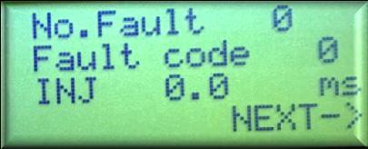
12 MODE Gear SWITCH No.Fault Fault code MODE GEAR_POSITION SWITCH_1 NUMBER_FAULT_DETECTION FAULT_CODE INJ INJECTION_DUTATION ms IGN IGNITION_TIMING BTDC ISC ISC_VALVE % O2 Trim O2_SENSOR_FUEL_TRIM % YCC-AT YCC_AT_MOTOR_DUTY % Sheave PRIMARY_SHEAVE_POSITION_SENSOR_VOLTAGE V SWITCH2 SWITCH_2 I-Shift I_SHIFT_POSITION 12
13 5. Engine analysis mode LCD DISPLAY Code No. Description Unit ThroAngle1 D01 Throttle position sensor signal ⁰ AtmPR D02 Atmospheric pressure 0-126Kpa INAirP1 D03 Intake air pressure Kpa INAirP2 D04 Intake air pressure Kpa INAirTE D05 Intake air temperature ⁰ C CoolantTE D06 Coolant temperature ⁰ C Sp.Pulse D07 Front/Rear wheel speed pulse Tilt sensor D08 Lean angle sensor 0-5 V BAT volt D09 Fuel System voltage (Battery voltage) 0-18 V Oil Temp D10 Oil temperature ⁰ C Eng Temp D11 Engine temperature ⁰ C Fan Temp D12 Cooling fan temperature ⁰ C ThroAngle2 D13 Throttle position sensor signal 2 ⁰ Acc.Pos1 D14 Accelerator position sensor signal 1 ⁰ 13
14 Acc.Pos2 D15 Accelerator position sensor signal 2 ⁰ Wh.Pulse D16 Front wheel speed pulse Step Side stand SW D20 [Side stand switch][blue/yellow lead of the ECU] on/off Clutch SW D21 Neutral switch and clutch switch on/off Throttle SW D24 Throttle switch on/off Gear.Pos SW D25 Gear position switch on/off GripWarmer D26 Grip warmer <ACTION> ThumbWarmer D27 Thumb warmer operation <ACTION> Suspension D29 Suspension solenoid on/off <ACTION> it is show on/off IG coil#1 D30 Cylinder #1 or #1-1 ignition coil <ACTION> IG coil#2 D31 Cylinder #2 or #2-1 ignition coil <ACTION> IG coil#3 D32 Cylinder #3 or #1-2 ignition coil <ACTION> IG coil#4 D33 Cylinder #4 or #2-2 ignition coil <ACTION> In Funnel servo D34 Intake funnel servo motor <ACTION> Wiper moto D35 Wiper motor <ACTION> Injector#1 D36 Injector #1 <ACTION> Injector#2 D37 Injector #2 <ACTION> 14
15 Injector#3 D38 Injector #3 <ACTION> Injector#4 D39 Injector #4 <ACTION> SecInjtor#1 D40 Secondary injector #1 <ACTION> SecInjtor#2 D41 Secondary injector #2 <ACTION> SecInjtor#3 D42 Secondary injector #3 <ACTION> SecInjtor#4 D43 Secondary injector #4 <ACTION> Purge CutValve D46 Purge cut valve solenoid <ACTION> Steering Damper D47 Steering damper solenoid <ACTION> AirInducSystem D48 Air induction system solenoid <ACTION> IntakeSolenoid D49 Intake solenoid <ACTION> Main Relay D50 Main relay/fuel pump relay <ACTION> RadiatorFan D51 Radiator fan motor relay <ACTION> Head light D52 Headlight relay <ACTION> EXUPServo D53 EXUP servo motor <ACTION> ⁰ ISC D54 ISC(idle speed control) valve/fid (fast idle solenoid) <ACTION> 15
16 Decomp D55 Decompression solenoid <ACTION> V Sub-thro D56 Sub-throttle servo motor <ACTION> ⁰ GripWarmer D57 Grip warmer <ACTION> PasGripWarmer D59 Passenger grip warmer relay <ACTION> EEPROM DTC D60 EEPROM fault code display Value RStory DTC D61 Malfunction history code display Value Story DTC D62 Malfunction history code erasure <ACTION for erase> Value Reinstatement D63 Malfunction code reinstatement <ACTION for erase> Value SettingHis D64 Setting history display Value SettingMap D65 Setting map erasure <ACTION> Value ISC Erasure D67 ISC correction value erasure <ACTION for erase> Value EthanolMixed D68 Switching correction value for ethanol mixed fuel <ACTION for erase> value ECU Ver D70 Program version number value PriSheave D71 Primary sheave position voltage SecSheave D72 Secondary sheave speed pulse Mode SW D74 Mode switch on/off ShiftSW D75 Shift switch on/off YCC-AT Motor D77 YCC-AT motor relay <ACTION> PriSheave D78 Primary sheave position initialization <ACTION> CruiseResume D80 Cruise control resume switch on/off CruiseSet D81 Cruise control set switch on/off CruiseCancel D82 Cruise control cancel switch on/off BrakeSW D83 Brake switch on/off 16
17 6. CO Adjustment mode Intensity Adjustment in Low RPM - CO Adjustment in Cylinder #2,C2 Mixture - CO Adjustment in Cylinder #3,C3 Mixture - CO Adjustment in Cylinder #4,C4 Mixture LCD DISPLAY Description STEP C1 Mixture C1 Mixture Cylinder # C2 Mixture C3 Mixture C4 Mixture C2 Mixture Cylinder #2 C3 Mixture Cylinder #3 C4 Mixture Cylinder # DTC Error. is the recording function, it records the engine when abnormal Codes and description DTC Error Code of problem Description 11 - No normal signals are received from the cylinder identification sensor 12 - No normal signals are received from the crankshaft position sensor. Possible caused Wiring connector is damaged The circuit is open or shorted in the main wiring Crankshaft sensor is damaged Magneto wheel is broken The sensor is error installation 13 D03 Intake Air Pressure sensor#1 found Wiring connector is damaged 17
18 the open circuit or shorted circuit 14 D03 Intake Air Pressure sensor#1 found the error in hose system malfunction The circuit is open or shorted in the main wiring Intake Air Pressure sensor is broken Module sensor is loosen TPS is wrong installation IAP sensor is stuck 15 D01 TPS is broken or short circuit Wiring connector is damaged The circuit is open or shorted in the main wiring TPS is malfunction Module sensor is wrong installation 16 D01 Stuck of throttle position sensor is detected 17 D53 EXUP servo motor circuit (open or short circuit) Module sensor is wrong installation TPS is malfunction Connection is wrong The wiring is not connected 18 D53 EXUP servo motor is stuck The wiring is not connected Servo motor is malfunction 19 D20 Open circuit is detected in the input lead from the Side Stand switch to the ECM The connection of side stand switch is damaged The main wiring connection 20 D02 D03 When the main switch is On, the atmospheric pressure sensor voltage and intake air pressure sensor voltage differ greatly The wiring connector is damaged the main wiring is open or short circuit Intake Air Pressure sensor is malfunction 18
19 21 D06 Cooling temperature sensor open or short circuit The wiring connector is damaged the main wiring is open or short circuit Intake Air Pressure sensor is malfunction 22 D05 Intake air temperature sensor open or short circuit The wiring connector is damaged the main wiring is open or short circuit Intake Air Temperature sensor is malfunction or module sensor is wrong installation 23 D02 Atmospheric pressure sensor open or short circuit The wiring connector is damaged the main wiring is open or short circuit Barometer sensor is malfunction 24 - No normal signal is received from the O2 Sensor, the O2sensor fault The wiring connector is damaged the main wiring is open or short circuit O2 sensor is malfunction or wrong installation Fuel pump is not stable 25 D04 The intake air pressure sensor#2 found the open or short circuit The wiring connector is damaged the main wiring is open or short circuit Intake Air Pressure sensor is malfunction 26 D04 Intake Air Pressure sensor#2 found the error in hose or tube system malfunction Module sensor is loosen Wrong installation for throttle body Intake air pressure sensor is stuck 27 D10 Oil temperature sensor The wiring connector is damaged 19
20 (Open or short circuit) 28 D11 Engine temperature sensor - open or short circuit is detected 29 - Decompression thermostat (open or short circuit) 30 D08 Rollover signal is received from the lean angle sensor The main wiring is open or short circuit EOT(Engine oil temperature) sensor is malfunction Wrong installation for the module sensor The wiring connector is damaged The main wiring is open or short circuit Engine temperature sensor is malfunction Wrong installation for the module sensor The bike gets accident Wrong installation for the angle sensor or malfunction 33 D30 Ignition coil#1 broken circuit or fault The wiring connector is damaged Found the error in Ignition coil #1 The Ignition coil#1 is malfunction 34 D31 Ignition coil#2 broken circuit or fault The wiring connector is damaged Found the error in Ignition coil #2 The Ignition coil#2 is malfunction 35 D32 Ignition coil#3 broken circuit Or fault 36 D33 Ignition coil#4 broken circuit Or fault The wiring connector is damaged Found the error in Ignition coil #3 The Ignition coil#3 is malfunction The wiring connector is damaged Found the error in Ignition coil #4 The Ignition coil#4 is malfunction 20
21 37 D54 Engine Idle Speed Control is too high A: A indicates another part that not in the ISC ( will hear the sound of ISC working ) B: B indicates that the ISC part is malfunction ( will not hear the sound of ISC working) 39 D36 D37 D38 D39 Fuel Injector is open or short circuit 41 D08 Lean angle sensor is open or short circuit A-1: Use the Diagnostic tool to find the problem A-2: The signal from the front wheel is abnormal A-3: Throttle body is not closed properly, could be from the hose. A-4: The leaked air from the throttle body A-5: The leaked air from the ISC part A-6: Air for throttle body or the ISC part is too much A-7: ISC part doesn t work properly A-8: The ECM is malfunction B-1: Use the Diagnostic tool to find the problem B-2: The connection between the ISC connector is not connected properly B-3: The connection between the ECM connector is not connected properly B-4: The main wiring connection B-5: The installation for ISC part B-6: The battery is abnormal B-7: The ISC part doesn t work properly B-8: The ECM is malfunction B-9: Delete the error code The wiring connector is damaged The short or open circuit in main wiring Fuel Injector is malfunction The ECM is malfunction Wrong installation for module sensor The short or open circuit in main wiring The lean angle sensor is damaged The ECM is malfunction 21
22 42 A:D07 B:D21 C:D21 No normal signals received from the speed sensor or Neutral switch open or short circuit A: Wheel sensor didn t receive the signal B: Gear switch found the open or short circuit C: Clutch switch found the open or short circuit A-1: Use the Diagnostic tool to find the problem A-2: The connectors that connected between the wheel sensors(front /rear) may damaged A-3:The connection from ABS ECM may damaged A-4:The connection between wiring of wheel sensors( front/rear) may damaged A-5:The ECM is malfunction A-6:The ABS function in ECM is malfunction B-1: Use the Diagnostic tool to find the problem B-2:The connection at the gear switch connector B-3:The connection between ECM B-4:The connection between main wiring B-5: Gear switch position is abnormal B-6: Gear switch position is abnormal at Neutral gear B-7:The ECM is malfunction C-1: Use the Diagnostic tool to find the problem C-2: Clutch adjustment C-3: The connection at the clutch switch connector C-4: The connection between ECM C-5: The connection between main wiring C-6: Clutch switch is malfunction C-7: The ECM is malfunction 43 D09 D50 Power supply to the injectors and the fuel pump is abnormal 44 D60 Write or read EEPROM error (CO adjustment value) The ECM connection The connection at the main wiring The ECM is malfunction 00 The ECM is malfunction 01 The error data at EEPROM for CO adjustment 22
23 inside cylinder#1 02 The error data at EEPROM for CO adjustment inside cylinder#2 03 The error data at EEPROM for CO adjustment inside cylinder#3 04 The error data at EEPROM for CO adjustment inside cylinder#4 11 The error data at EEPROM in ISC part 45 - Power cutoff by oneself fault Wiring at the battery connection The Relay start connection Condition in spare Fuse The connection at main wiring The ECM is malfunction 46 - Power supply is abnormal: Charging system is malfunction regulator is abnormal 47 D56 Sub throttle Servo Motor fault 48 - AI System Solenoid 50 - ECU memory fault The ECM is malfunction 59 D14 D15 Throttle position sensor in throttle cable pulley is fault 60 D01 Throttle servo motor is open or short circuit The wiring connector Open or short circuit in main wiring TPS sensor The ECM is malfunction Wrong installation at module sensor The wiring connector Open or short circuit in main wiring TPS sensor The ECM is malfunction Wrong installation at module sensor 61 D54 ISC(Idle Speed Control is open The connection at the ISC connector 23
24 or short circuit 84 D45 VVA: Variable Valve Actuator is open or short circuit The connection at the ECM and the main wiring The main wiring connection The ISC set is malfunction The ECM is malfunction The connection at the VVA solenoid wiring The connection at the ECM and the main wiring The main wiring connection VVA solenoid is malfunction The ECM is malfunction 24


25 8. Connection Process Step 1. Turn the key at the switch off Step 2. Connect the Doctor API wiring with the connector Step 3. After the connection is completed, it will show at picture Picture 1 Picture 2 Step 4. The picture 2 shows the modes - Monitoring Mode as real time - Analysis Mode - Special Func: Step 5. To choose a mode 5.1 Press the M button 5.2 Turn the key at Ignition On 25


26 5.3 The screen shows the chosen mode 6. Every time when need to change the mode, the process must be repeated from step 1 9. Sample when using the Doctor API with Yamaha R3 1. Monitoring Mode 2. Analysis ThrottleAngle1=Throttle angle degree#1 ( D01) INAirPR1 = Intake Air Pressure#1 ( D03) INAir TE = Intake Air Temperature( D05) 26


 Tilt Sensor =")


 IG Coil#1 =")

27 Coolant TE = Coolant Temperature/ Engine Oil Temperature (D06) Sp. Pulse = Signal that received from the Speed Pulse( D07) Tilt Sensor = Lean Angle Sensor( D08) BAT volt = Battery Voltage( D09) Sidestand SW = Side Stand Switch( D20) Clutch SW = Clutch Switch( D21) IG Coil#1 = Ignition Coil# 1 ( D30) <M> ACT = press Mode to test the function for Coil# 1 27
 <M> ACT = press Mode to test the")

 <M> ACT = press Mode to test the")

28 IG Coil#2 = Ignition Coil# 2( D31) <M> ACT = press Mode to test the function for Coil# 2 Injectorl#1 = Injector#1( D36) <M> ACT = press Mode to test the function for Injector#1 Injector#2 = Injector# 2( D37) <M> ACT = press Mode to test the function for Injector#2 AirInducSystem = Air Induction System Valve(D48) <M> ACT = press Mode to test the function for Air Induction System Valve Main Relay = Main Relay( D50) <M> ACT = press Mode to test the function for Main Relay RadiatorFan = Radiator Fan( D51) < Down> Next = press Down to see the next data <M> ACT = press Mode to test the function for Radiator Fan 28
 <M> ACT = press Mode to test the function for Idle Speed")
 CStory DTC = The no.")
 <M> ACT")
29 Head light = Head Light( D52) <M> ACT = press Mode to test the function for Head light ISC = Idle Speed Control ( D54) <M> ACT = press Mode to test the function for Idle Speed Control EEPROM DTC = The error data that recorded in memory EEPROM( D60) RStory DTC = The error code that recorded in memory ( D61) CStory DTC = The no. of the error sensor that recorded in memory( D62) <M> ACT = press Mode to delete the error data that recorded in the memory Reinstatement = Reinstatement Valve( D63) <M> ACT = press Mode to test the function 29

 systems.")
30 2. CO Adjustment for intensity during Idle Stage C1 Mixture = Adjust the CO in cylinder #1 <Down> Next = press Down to reduce input <Up> Exit = press Up to increase input <M> ACT = Exit the system C2 Mixture = = Adjust the CO in cylinder #2 <Down> Next = press Down to reduce input <Up> Exit = press Up to increase input <M> ACT = Exit the system 10. Function Bootloader This function will be used for upgrading the new firmware. When new motorcycle model launched in the market, the program will be updated. The upgrading will be processed by Wireless (Bluetooth) systems. 30
Instruction Manual for Diagnostic Tool DOCTOR API HONDA
 Instruction Manual for Diagnostic Tool DOCTOR API HONDA API Tech Co.,Ltd. www.apitechonline.com Facebook.com/apitechonline Tel.02-948-8680 Fax.02-948-8980 Diagnostic Tool1 Content Page 1. Product s components
G - TESTS W/CODES - 2.2L
 G - TESTS W/CODES - 2.2L 1994 Toyota Celica 1994 ENGINE PERFORMANCE Toyota 2.2L Self-Diagnostics Celica INTRODUCTION If no faults were found while performing F - BASIC TESTING, proceed with self-diagnostics.
To enter the diagnostic mode and check the existing error codes in memory, do the following:
 Error codes Yamaha R1. Explanation and diagnosis. To enter the diagnostic mode and check the existing error codes in memory, do the following: 1. Turn off the ignition, the engine stop button to put in
DTC Summaries. NipponDenso V12 Engine Management
 DTC Summaries NipponDenso V12 Engine Management OBD II MONITORING CONDITIONS: When testing for DTC reoccurrence, it can be determined if the Service Drive Cycle was of sufficient length by performing a
MULTIPOINT FUEL INJECTION (MPI) <4G63-Turbo>
 <4G63-Turbo>") 13B-1 GROUP 13B MULTIPOINT FUEL INJECTI (MPI) CTENTS GENERAL INFORMATI........ 13B-2 SENSOR....................... 13B-8 THROTTLE VALVE OPENING ANGLE CTROL.............. 13B-9 FUEL INJECTI
13B-1 GROUP 13B MULTIPOINT FUEL INJECTI (MPI) CTENTS GENERAL INFORMATI........ 13B-2 SENSOR....................... 13B-8 THROTTLE VALVE OPENING ANGLE CTROL.............. 13B-9 FUEL INJECTI
ProECU Subaru BRZ Toyota GT86 Scion FR-S
 ProECU Subaru BRZ Toyota GT86 Scion FR-S DTC List 2012-onward Model Year v1.0 Engine DTC List P000A Camshaft Position "A" - Timing Slow Response Bank 1 P000B Camshaft Position "B" - Timing Slow Response
5. Engine Control Module (ECM) I/O Signal
 I/O Signal") 5. A: ELECTRICAL SPECIFICATION B134 B135 B136 B137 17 16 15 14 13 12 11 10 9 8 27 26 25 24 23 22 21 20 19 18 34 33 32 31 30 29 28 19 18 17 16 15 14 13 12 11 10 9 8 27 26 25 24 23 22 21 20 35 34 33 32 31
5. A: ELECTRICAL SPECIFICATION B134 B135 B136 B137 17 16 15 14 13 12 11 10 9 8 27 26 25 24 23 22 21 20 19 18 34 33 32 31 30 29 28 19 18 17 16 15 14 13 12 11 10 9 8 27 26 25 24 23 22 21 20 35 34 33 32 31
Powertrain DTC Summaries EOBD
 Powertrain DTC Summaries Quick Reference Diagnostic Guide Jaguar X-TYPE 2.0 L 2002.25 Model Year Refer to page 2 for important information regarding the use of Powertrain DTC Summaries. Jaguar X-TYPE 2.0
Diagnostic Trouble Code (DTC) List - Vehicle
 List - Vehicle") Document ID# 850406 2002 Pontiac Firebird Diagnostic Trouble Code (DTC) List - Vehicle DTC DTC 021 and/or 031 DTC 022 and/or 032 DTC 023 or 033 DTC 24/34 DTC 025 and/or 035 DTC 041 DTC 042 DTC 043 DTC
Document ID# 850406 2002 Pontiac Firebird Diagnostic Trouble Code (DTC) List - Vehicle DTC DTC 021 and/or 031 DTC 022 and/or 032 DTC 023 or 033 DTC 24/34 DTC 025 and/or 035 DTC 041 DTC 042 DTC 043 DTC
9. Subaru Select Monitor
 9. A: OPERATION 1. HOW TO USE SUBARU SELECT MONI- TOR 1) Prepare the kit. CAUTION: Do not connect the scan tools except for Subaru Select
Hyundai - Specific Trouble Codes
 Hyundai - Specific Trouble Codes P1100 Map Sensor - Malfunction P1101 Map Sensor - Abnormal P1102 Map Sensor - Low Input P1103 Map Sensor - High Input P1104 Air Flow P1105 Air Flow - Abnormal P1106 Air
DIAGNOSTIC TROUBLE CODE CHART HINT:
 DIAGNOSTICS DIAGNOSTIC TROUBLE CODE CHART HINT: SFI SYSTEM (1MZFE) 05241 Parameters listed in the chart may not be exactly the same as your reading due to the type of instrument or other factors. If a
EvoX EFI ECU Pinouts Last Updated Tuesday, 24 April :40
 HOW TO: Reset your Fuel trims... Open your bonnet, open the fuse box, pull out 7.5A number 2 fuse, this is battery backup for your main ECU, remove for 2 seconds, and replace. Your fuel trims and learned
MULTIPORT FUEL SYSTEM (MFI) <2.4L ENGINE>
 <2.4L ENGINE>") 13A-1 GROUP 13A MULTIPORT FUEL SYSTEM (MFI) CONTENTS GENERAL DESCRIPTION......... 13A-2 FUEL INJECTION CONTROL...... 13A-5 THROTTLE VALVE OPENING ANGLE CONTROL..................... 13A-6
13A-1 GROUP 13A MULTIPORT FUEL SYSTEM (MFI) CONTENTS GENERAL DESCRIPTION......... 13A-2 FUEL INJECTION CONTROL...... 13A-5 THROTTLE VALVE OPENING ANGLE CONTROL..................... 13A-6
ARTICLE BEGINNING INTRODUCTION SELF-DIAGNOSTIC SYSTEM RETRIEVING DTCS ENGINE PERFORMANCE Volkswagen Self-Diagnostics - Gasoline
 Article Text ARTICLE BEGINNING 1996 ENGINE PERFORMANCE Volkswagen Self-Diagnostics - Gasoline Cabrio, Golf III, GTI, Jetta III, Passat INTRODUCTION If no faults were found while performing preliminary
Diagnostic Trouble Code (DTC) table
 table") Page 1 of 40 01-19 Diagnostic Trouble Code (DTC) table Note: When malfunctions occur in monitored sensors or components, Diagnostic Trouble Codes (DTCs) are stored in DTC memory with a description of the
Page 1 of 40 01-19 Diagnostic Trouble Code (DTC) table Note: When malfunctions occur in monitored sensors or components, Diagnostic Trouble Codes (DTCs) are stored in DTC memory with a description of the
MULTIPOINT FUEL INJECTION (MPI) <4G63-Non-Turbo>
 <4G63-Non-Turbo>") 13A-1 GROUP 13A MULTIPOINT FUEL INJECTI (MPI) CTENTS GENERAL INFORMATI........ 13A-2 FUEL INJECTI CTROL...... 13A-6 IDLE SPEED CTROL (ISC)..... 13A-7 IGNITI TIMING AND DISTRIBUTI CTROL........
13A-1 GROUP 13A MULTIPOINT FUEL INJECTI (MPI) CTENTS GENERAL INFORMATI........ 13A-2 FUEL INJECTI CTROL...... 13A-6 IDLE SPEED CTROL (ISC)..... 13A-7 IGNITI TIMING AND DISTRIBUTI CTROL........
ProECU Subaru DIT. DTC List 2012-onward Model Year. v1.0
 ProECU Subaru DIT DTC List 2012-onward Model Year v1.0 Engine DTC List P000A A CAMSHAFT POSITION SLOW RESPONSE (BANK 1) P000B B CAMSHAFT POSITION SLOW RESPONSE (BANK 1) P000C A CAMSHAFT POSITION SLOW RESPONSE
DATA LIST / ACTIVE TEST
 2UZFE ENGINE CONTROL SYSTEM SFI SYSTEM 43 DATA LIST / ACTIVE TT 1. DATA LIST HINT: Using the intelligent tester's DATA LIST allows switch, sensor, actuator and other item values to be read without removing
Position of Parts in Engine Compartment
 [1UZ FE] Position of Parts in Engine Compartment A 1 A/C Ambient Temp. Sensor E 4 Engine Coolant Temp. Sensor (Water Temp. Sensor A 2 A/C Dual Pressure SW and A/C High Pressure SW (for Cooling Fan)) A
THROTTLE BODIES 7-6. c. Connect the pressure gauge 2 and adapter 3 to the fuel hose (fuel tank to primary
 THROTTLE BODIES EAS26980 CHECKING THE INJECTORS 1. Check: Injectors Damage Replace. EAS26990 CHECKING THE THROTTLE BODIES 1. Check: Throttle bodies Cracks/damage Replace the throttle bodies as a set. 2.
C6 Corvette DIC Codes
 C6 Corvette DIC Codes B0159 Outside Air Temp Sensor B2910 Steering Column Lock Password Incorrect B0164 Pass Compartment Temp Sensor B2981 Right Front Door Handle Switch B0174 Output Air Temp Sensor 1
Powertrain DTC Summaries EOBD
 Powertrain DTC Summaries Quick Reference Diagnostic Guide Jaguar X-TYPE 2.5L and 3.0L 2001.5 Model Year Revised January, 2002: P0706, P0731, P0732, P0733, P0734, P0735, P0740, P1780 POSSIBLE CAUSES Revised
5. Control System CONTROL SYSTEM FUEL INJECTION (FUEL SYSTEM) A: GENERAL. FU(STi)-27
 A: GENERAL. FU(STi)-27") W1860BE.book Page 27 Tuesday, January 28, 2003 11:01 PM 5. Control System A: GENERAL The ECM receives signals from various sensors, switches, and other control modules. Using these signals, it determines
W1860BE.book Page 27 Tuesday, January 28, 2003 11:01 PM 5. Control System A: GENERAL The ECM receives signals from various sensors, switches, and other control modules. Using these signals, it determines
5. Control System CONTROL SYSTEM FUEL INJECTION (FUEL SYSTEM) A: GENERAL FU(H4DOTC)-29
 A: GENERAL FU(H4DOTC)-29") W1860BE.book Page 29 Tuesday, January 28, 2003 11:01 PM 5. Control System A: GENERAL The ECM receives signals from various sensors, switches, and other control modules. Using these signals, it determines
W1860BE.book Page 29 Tuesday, January 28, 2003 11:01 PM 5. Control System A: GENERAL The ECM receives signals from various sensors, switches, and other control modules. Using these signals, it determines
Powertrain DTC Summaries EOBD
 Powertrain DTC Summaries Quick Reference Diagnostic Guide Jaguar S-TYPE V6, V8 N/A and V8 SC 2002.5 Model Year Refer to pages 2 9 for important information regarding the use of Powertrain DTC Summaries.
Diagnostic Trouble Codes (continued) GM Specific Codes
 GM Specific Codes") 85 GM Specific Codes P11XX Fuel and Air Metering P1106 MAP Sensor Circuit Intermittent High Voltage P1107 MAP Sensor Circuit Intermittent Low Voltage P1108 BARO to MAP Signal Comparison Too High P1111
85 GM Specific Codes P11XX Fuel and Air Metering P1106 MAP Sensor Circuit Intermittent High Voltage P1107 MAP Sensor Circuit Intermittent Low Voltage P1108 BARO to MAP Signal Comparison Too High P1111
MULTIPOINT FUEL INJECTION (MPI) <4G9>
 <4G9>") MULTIPOINT FUEL INJECTION (MPI) 13C-1 MULTIPOINT FUEL INJECTION (MPI) CONTENTS GENERAL................................. 2 Outline of Changes............................ 2 GENERAL INFORMATION...................
MULTIPOINT FUEL INJECTION (MPI) 13C-1 MULTIPOINT FUEL INJECTION (MPI) CONTENTS GENERAL................................. 2 Outline of Changes............................ 2 GENERAL INFORMATION...................
ENGINE CONTROL SYSTEM. 1. General ENGINE 3VZ FE ENGINE
 ENGINE 3VZ FE ENGINE 69 ENGINE CONTROL SYSTEM 1. General The engine control system for the 3VZ FE engine has the same basic construction and operation as for the 2VZ FE engine. However, the sequential
Author: David Christensen Brand: Toyota Type ECU: Powertrain Toyota (CAN) Date: 21/04/2015 Version: V0.1 ***DRAFT ONLY***
 Date: 21/04/2015 Version: V0.1 ***DRAFT ONLY***") Author: David Christensen Brand: Toyota Type ECU: Powertrain Car: Toyota (CAN) Date: 21/04/2015 Version: V0.1 ***DRAFT ONLY*** 2101 Check Engine Indicator Bit 2101 Number of errors ECU - 2103 Fuel System
Author: David Christensen Brand: Toyota Type ECU: Powertrain Car: Toyota (CAN) Date: 21/04/2015 Version: V0.1 ***DRAFT ONLY*** 2101 Check Engine Indicator Bit 2101 Number of errors ECU - 2103 Fuel System
DIAGNOSTIC TROUBLE CODE DEFINITIONS
 DIAGNOSTIC TROUBLE CODE DEFINITIONS DIAGNOSTIC TROUBLE CODE DEFINITIONS DTC Description P0010 Variable Valve Timing Circuit Malfunction (Bank 1) P0020 Variable Valve Timing Circuit Malfunction (Bank 2)
DIAGNOSTIC TROUBLE CODE CHART
 DIAGNOSTIC TROUBLE CODE CHART 05 35 HINT: As for the vehicle for MEXICO, refer to Repair Manual 2003 COROLLA MATRIX (Pub. No. RM940U). Parameters listed in the chart may not be exactly the same as your
L (LU4, LJ3, L88) used in Saab 9-5 ENGINE DIAGNOSTIC PARAMETERS
 used in Saab 9-5 ENGINE DIAGNOSTIC PARAMETERS") Catalytic Converter Monitoring P0420 Front vs. Rear O2 sensor signal Evaluated data 1,75 times FTP std 80 (unitless) Coolant temp Throttle Delta load, positive Delta load, negative Engine speed, man. trans
Catalytic Converter Monitoring P0420 Front vs. Rear O2 sensor signal Evaluated data 1,75 times FTP std 80 (unitless) Coolant temp Throttle Delta load, positive Delta load, negative Engine speed, man. trans
Diagnostic Trouble Code (DTC) memory, checking and erasing
 memory, checking and erasing") Page 1 of 49 01-12 Diagnostic Trouble Code (DTC) memory, checking and erasing Check DTC Memory (function 02) - Connect VAS5051 tester Page 01-7 and select vehicle system "01 - Engine electronics". Engine
Page 1 of 49 01-12 Diagnostic Trouble Code (DTC) memory, checking and erasing Check DTC Memory (function 02) - Connect VAS5051 tester Page 01-7 and select vehicle system "01 - Engine electronics". Engine
DIAGNOSIS SYSTEM DESCRIPTION CHECK ENGINE WARNING LIGHT CHECK
 FI146 EFI SYSTEM (3VZE) DIAGNOSIS SYSTEM DESCRIPTION The engine (engine and ECT) ECU contains a builtin, selfdiagnosis system which detects troubles within the engine signal network and flashes the warning
2.8 Liter VR6 2V Fuel Injection & Ignition, Engine Code(s): AAA m.y
: AAA m.y") 2.8 Liter VR6 2V Fuel Injection & Ignition, Engine Code(s): AAA m.y. 1996-1997 01 - On Board Diagnostic (OBD) On Board Diagnostic (OBD II) Malfunction Indicator Lamp (MIL) On Board Diagnostic (OBD II),
2.8 Liter VR6 2V Fuel Injection & Ignition, Engine Code(s): AAA m.y. 1996-1997 01 - On Board Diagnostic (OBD) On Board Diagnostic (OBD II) Malfunction Indicator Lamp (MIL) On Board Diagnostic (OBD II),
DIAGNOSTIC TROUBLE CODE CHART
 DIAGNOSTIC TROUBLE CODE CHART HINT: DI231 Parameters listed in the chart may not be exactly the same as your readings due to the type of instrument or other factors. If a malfunction code is displayed
DIAGNOSTIC TROUBLE CODE CHART (SAE Controlled)
") 1MZFE ENGINE EG2404 (SAE Controlled) HINT: Parameters listed in the chart may not be exactly the same as your reading due to the type of instrument or other factors. DTC No. Detection Item Diagnostic Trouble
1MZFE ENGINE EG2404 (SAE Controlled) HINT: Parameters listed in the chart may not be exactly the same as your reading due to the type of instrument or other factors. DTC No. Detection Item Diagnostic Trouble
DTC P0172 Fuel Trim System Rich
 Page 1 of 6 1997 Chevrolet Cavalier Cavalier, Sunfire (VIN J) Service Manual Document ID: 47788 DTC P0172 Fuel Trim System Rich System Description A Closed Loop air/fuel metering system is used to provide
cylinder cars / trucks (except Saturn S-series cars) ENGINE DIAGNOSTIC PARAMETERS
 ENGINE DIAGNOSTIC PARAMETERS") 2001 4-cylinder cars / trucks (except Saturn S-series cars) ENGINE DIAGNOSTIC S SECONDARY S AND Manifold Pressure/Throttle Position Sensor Manifold Pressure/Throttle Position Sensor Manifold Pressure Too
2001 4-cylinder cars / trucks (except Saturn S-series cars) ENGINE DIAGNOSTIC S SECONDARY S AND Manifold Pressure/Throttle Position Sensor Manifold Pressure/Throttle Position Sensor Manifold Pressure Too
EMISSION CONTROL SYSTEM
 WJ EMISSION CONTROL SYSTEM 25-1 EMISSION CONTROL SYSTEM CONTENTS page ON-BOARD DIAGNOSTICS 3.1L DIESEL ENGINE... 1 ON-BOARD DIAGNOSTICS 3.1L DIESEL ENGINE INDEX page GENERAL INFORMATION SYSTEM DESCRIPTION
MULTIPORT FUEL SYSTEM (MFI) <3.8L ENGINE>
 <3.8L ENGINE>") 13B-1 GROUP 13B MULTIPORT FUEL SYSTEM (MFI) CONTENTS GENERAL DESCRIPTION......... 13B-2....................... 13B-5 ACTUATOR.................... 13B-5 FUEL INJECTION CONTROL...... 13B-7
13B-1 GROUP 13B MULTIPORT FUEL SYSTEM (MFI) CONTENTS GENERAL DESCRIPTION......... 13B-2....................... 13B-5 ACTUATOR.................... 13B-5 FUEL INJECTION CONTROL...... 13B-7
DTC P0171 SYSTEM TOO LEAN (BANK 1) DTC P0174 SYSTEM TOO LEAN (BANK 2)
 DTC P0174 SYSTEM TOO LEAN (BANK 2)") 05498 DIAGNOSTICS DTC P0171 SYSTEM TOO LEAN (BANK 1) 05EXR06 DTC P0172 SYSTEM TOO RICH (BANK 1) DTC P0174 SYSTEM TOO LEAN (BANK 2) DTC P0175 SYSTEM TOO RICH (BANK 2) CIRCUIT DESCRIPTION The fuel trim is
05498 DIAGNOSTICS DTC P0171 SYSTEM TOO LEAN (BANK 1) 05EXR06 DTC P0172 SYSTEM TOO RICH (BANK 1) DTC P0174 SYSTEM TOO LEAN (BANK 2) DTC P0175 SYSTEM TOO RICH (BANK 2) CIRCUIT DESCRIPTION The fuel trim is
EMISSION CONTROL SYSTEM
 WJ EMISSION CONTROL SYSTEM 25-1 EMISSION CONTROL SYSTEM TABLE OF CONTENTS page ON-BOARD DIAGNOSTICS 3.1L DIESEL ENGINE... 1 ON-BOARD DIAGNOSTICS 3.1L DIESEL ENGINE TABLE OF CONTENTS page DESCRIPTION AND
L (LL8) Engine Diagnostic Parameters
 Engine Diagnostic Parameters") Cam Shaft Position Actuator Control VCP System Performance VCP = variable cam phaser VCP Crank/Cam Correlation Error P0013 P0014 P0016 DESCRIPTION Detects an open or shorted control circuit by monitoring
Cam Shaft Position Actuator Control VCP System Performance VCP = variable cam phaser VCP Crank/Cam Correlation Error P0013 P0014 P0016 DESCRIPTION Detects an open or shorted control circuit by monitoring
2002 Buick Rendezvous - AWD
 2002 Buick Rendezvous - AWD DTC P0410 Description The control module activates the secondary air injection (AIR) system by grounding both the pump relay and the vacuum control solenoid control circuits.
Telephone: Fax: VAT Registration No.:
 Telephone: Fax: VAT Registration No.: Name: Manufacturer: Ford Address: Model: Year: 1994 Registration: Tel - Private: Tel - Business: Mileage: Job number: Terminal side Wire side Component/circuit description
ENGINE MANAGEMENT SYSTEM. System Sensors
 ENGINE MANAGEMENT SYSTEM System Sensors Throttle position sensor - Used to relay throttle position information to the ECU. Throttle opening angle is used by the ECU to determine fuelling and ignition requirements
UIF Technology CO.,LTD.
 CONTENTS 1. INTRODUCTION MEMOScanner is newly developed by UIF TECH, specially designed for car owners or DIYs. With an MEMOScanner, you may quickly find out trouble causes of electronically controlled
EG1 189 EFI SYSTEM 5S FE ENGINE DIAGNOSIS SYSTEM
 5SFE ENGINE EG1189 DIAGNOSIS SYSTEM DESCRIPTION The ECU contains a builtin selfdiagnosis system by which troubles with the engine signal network are detected and a CHECK engine warning light on the combination
DI 3 ENGINE DIAGNOSTICS DI00H 22 PRE CHECK
 PRECHECK DI3 DI00H22 1. DIAGNOSIS SYSTEM (a) Description When troubleshooting OBD II vehicles, the only difference from the usual troubleshooting procedure is that you connect to the vehicle the OBD II
DI 3 ENGINE DIAGNOSTICS DI PRE CHECK
 FI0534 PRECHECK DI3 DI09603 1. DIAGNOSIS SYSTEM (a) Description When troubleshooting OBD II vehicles, the only difference from the usual troubleshooting procedure is that you connect to the vehicle the
SAS light Check Engine Malfunction Indicator Lamp
 SAS light Check Engine Malfunction Indicator Lamp Here's how to do it: In car ECM Diagnostics/ECM Reset procedure: 1) Sit in the driver's seat. 2) Turn the ignition key to the ON position and wait three
Five-digit error code First position: P - is for powertrain codes B - is for body codes C - is for chassis codes
 https://www.automotive-manuals.net Five-digit error code First position: P - is for powertrain codes B - is for body codes C - is for chassis codes The second position: 0 - the total for the OBD-II code
Powertrain DTC Summaries OBD II
 Powertrain DTC Summaries Quick Reference Diagnostic Guide Jaguar X-TYPE 2.5L and 3.0L 2002 Model Year Revised January, 2002: P0706, P0731, P0732, P0733, P0734, P0735, P0740, P1780 POSSIBLE CAUSES Revised
Malfunction Criteria and Threshold Value Adaptive value. Secondary Parameters with Enable Conditions. >50.8 S Engine load 9-45% Delta fuel adaptation
 DTC Error Message P0171 System Too Lean (Bank 1) Diagnostic Procedure Check fuel pump delivery and quantity. Refer to page 126. Check Fuel pressure regulator and residual pressure. Refer to Fuel Injection
Diagnostic Trouble Codes (continued) SAE Defined Codes
 SAE Defined Codes") 78 SAE Defined Codes P01XX Fuel and Air Metering P0100 Mass or Volume Airflow Circuit Problem P0101 Mass or Volume Airflow Circuit Range or Performance Problem P0102 Mass or Volume Airflow Circuit Low
78 SAE Defined Codes P01XX Fuel and Air Metering P0100 Mass or Volume Airflow Circuit Problem P0101 Mass or Volume Airflow Circuit Range or Performance Problem P0102 Mass or Volume Airflow Circuit Low
If a single test is completed entirely, but indicated as "not OK", a DTC will be stored in DTC memory. Check DTC Memory Page
 Page 1 of 43 01-77 Readiness code The readiness code appears as an 8-digit display in measuring value block 086, display field 1. Each of the 8 digits is allocated to a specific exhaust related system.
13A-1 FUEL CONTENTS MULTIPOINT FUEL INJECTION (MPI) FUEL SUPPLY... 13B
 FUEL SUPPLY... 13B") 13A-1 FUEL CONTENTS MULTIPOINT FUEL INJECTION (MPI)... 13A FUEL SUPPLY... 13B 13A-2 MULTIPOINT FUEL INJECTION (MPI) CONTENTS GENERAL INFORMATION... 3 SERVICE SPECIFICATIONS... 6 SEALANT... 6 SPECIAL TOOLS...
13A-1 FUEL CONTENTS MULTIPOINT FUEL INJECTION (MPI)... 13A FUEL SUPPLY... 13B 13A-2 MULTIPOINT FUEL INJECTION (MPI) CONTENTS GENERAL INFORMATION... 3 SERVICE SPECIFICATIONS... 6 SEALANT... 6 SPECIAL TOOLS...
OBD-II Diagnostic Powertrain (P) Trouble Codes
 Trouble Codes") OBD-II Diagnostic Powertrain (P) Trouble Codes Please use our new & improved search engine to find information on your trouble codes. Search Now! This list contains standard diagnostic trouble codes (DTC
OBD-II Diagnostic Powertrain (P) Trouble Codes Please use our new & improved search engine to find information on your trouble codes. Search Now! This list contains standard diagnostic trouble codes (DTC
DIAGNOSIS SYSTEM DESCRIPTION EG2 170
 EG2170 DIAGNOSIS SYSTEM DESCRIPTION The ECM contains a builtin self diagnosis system by which troubles with the engine signal network are detected and a malfunction indicator lamp on the combination meter
SECONDARY PARAMETERS AND ENABLE CONDITIONS
 SECONDARY S AND Manifold Pressure Sensor Rationality Manifold Pressure Too Low Manifold Pressure Too High Intake Air Temperature Sensor Shorted Intake Air Temperature Sensor Open Coolant Temperature Sensor
2002 ENGINE PERFORMANCE. Self-Diagnostics - RAV4. Before performing testing procedures, check for any related Technical Service Bulletins (TSBs).
.") 2002 ENGINE PERFORMANCE Self-Diagnostics - RAV4 INTRODUCTION NOTE: Before performing testing procedures, check for any related Technical Service Bulletins (TSBs). To properly diagnosis and repair this
2002 ENGINE PERFORMANCE Self-Diagnostics - RAV4 INTRODUCTION NOTE: Before performing testing procedures, check for any related Technical Service Bulletins (TSBs). To properly diagnosis and repair this
2010 Touring Models - Electronic Diagnostic - Diagnostic Trouble Codes (DTC) 2010_DTC_Codes -.pdf
 2010_DTC_Codes -.pdf") 2010 Touring Models - Electronic Diagnostic - Diagnostic Trouble Codes (DTC) 2010_DTC_Codes -.pdf Odometer Self-Diagnostics DTCs (Diagnostic Trouble Codes). Speedometer Self Diagnostics: The speedometer
2010 Touring Models - Electronic Diagnostic - Diagnostic Trouble Codes (DTC) 2010_DTC_Codes -.pdf Odometer Self-Diagnostics DTCs (Diagnostic Trouble Codes). Speedometer Self Diagnostics: The speedometer
Position of Parts in Engine Compartment
 ELECTRICAL WIRING ROUTING [3S GTE] Position of Parts in Engine Compartment A 1 A/C Ambient Temp. Sensor D 1 Date Link Connector 1 (Check Connector) A 2 A/C Condenser Fan Motor D 2 Distributor A 4 A/C Magnetic
Position of Parts in Engine Compartment
 ELECTRICAL WIRING ROUTING [5S FE] Position of Parts in Engine Compartment A 1 A/C Ambient Temp. Sensor D 1 Distributor A 2 A/C Condenser Fan Motor A 3 A/C Idle Up VSV E 1 ECT Solenoid A 4 A/C Magnet Clutch
ENGINE AND EMISSION CONTROL
 17-1 GROUP 17 ENGINE AND EMISSION CONTROL CONTENTS ENGINE CONTROL 17-2 GENERAL INFORMATION 17-2 AUTO-CRUISE CONTROL SYSTEM 17-3 GENERAL INFORMATION 17-3 CONSTRUCTION AND OPERATION 17-5 17-7 GENERAL INFORMATION
L (LK9, LQ8) when use in: Saab 9-3
 when use in: Saab 9-3") NOTE: Printing this file may require 8.5" x 14" (legal size) paper, depending on your printer setup. Catalytic Converter Monitoring P0420 Time for Rear O2 sensor signal Time for rear O2 to go low. Value
NOTE: Printing this file may require 8.5" x 14" (legal size) paper, depending on your printer setup. Catalytic Converter Monitoring P0420 Time for Rear O2 sensor signal Time for rear O2 to go low. Value
2010 Touring Models - Electronic Diagnostic - Diagnostic Trouble Codes (DTC)
") 2010 Touring Models - Electronic Diagnostic - Diagnostic Trouble Codes (DTC) Odometer Self-Diagnostics DTCs (Diagnostic Trouble Codes). Speedometer Self Diagnostics: The speedometer is capable of displaying
2010 Touring Models - Electronic Diagnostic - Diagnostic Trouble Codes (DTC) Odometer Self-Diagnostics DTCs (Diagnostic Trouble Codes). Speedometer Self Diagnostics: The speedometer is capable of displaying
Diagnostic Trouble Code (DTC) Root Cause. for Omnitek ECM 64A/66A/88A. & Remedial Action
 Root Cause. for Omnitek ECM 64A/66A/88A. & Remedial Action") Diagnostic Trouble Code (DTC) Root Cause & Remedial Action for Omnitek ECM 64A/66A/88A Omnitek Engineering Corp. 1945 S Rancho Santa Fe Rd. San Marcos, CA 92078 Tel. 760-591-0089 - Fax. 760-591-0880 -
Diagnostic Trouble Code (DTC) Root Cause & Remedial Action for Omnitek ECM 64A/66A/88A Omnitek Engineering Corp. 1945 S Rancho Santa Fe Rd. San Marcos, CA 92078 Tel. 760-591-0089 - Fax. 760-591-0880 -
4-2. FUEL INJECTION SYSTEM
 Fuel Injection System Components..1 Precautions in servicing..2 General..2 Connector/coupler...3 Fuse...3 ECU/various sensors.. 3 Electrical circuit inspection procedure. 4 Parts location...8 Wiring diagram....9
GROUP 13Ab. 13Ab-2 CONTENTS TROUBLESHOOTING STRATEGY.. DATA LIST REFERENCE TABLE... 13Ab-29 TROUBLE CODE DIAGNOSIS...
 13Ab-1 GROUP 13Ab CONTENTS TROUBLESHOOTING STRATEGY.. 13Ab-2 DATA LIST REFERENCE TABLE... 13Ab-29 TROUBLE CODE DIAGNOSIS..... 13Ab-2 FAIL-SAFE FUNCTION REFERENCE TABLE........................ 13Ab-20 DIAGNOSTIC
G ELECTRICAL WIRING ROUTING [5VZ FE] TOYOTA TACOMA (EWD517U) Position of Parts in Engine Compartment
![G ELECTRICAL WIRING ROUTING [5VZ FE] TOYOTA TACOMA (EWD517U) Position of Parts in Engine Compartment](/thumbs/82/86578697.jpg "G ELECTRICAL WIRING ROUTING [5VZ FE] TOYOTA TACOMA (EWD517U) Position of Parts in Engine Compartment") G ELECTRICAL WIRING ROUTING [5VZ FE] Position of Parts in Engine Compartment A 5 A/C Magnetic Clutch A 7 A/T Oil Temp. Sensor A22 ABS Actuator with ECU A23 Air Fuel Ratio Sensor (Bank 1 Sensor 1) A24 ADD
G ELECTRICAL WIRING ROUTING [5VZ FE] Position of Parts in Engine Compartment A 5 A/C Magnetic Clutch A 7 A/T Oil Temp. Sensor A22 ABS Actuator with ECU A23 Air Fuel Ratio Sensor (Bank 1 Sensor 1) A24 ADD
Appendix B. Data Parameters. Current and Past TMC Engines Covered in this Section. Fig. B-1. TL874fB01. Engine Control Systems II - Course 874 B-1
 Data Parameters Current and Past TMC Engines Covered in this Section Fig. B-1 TL874fB01 Engine Control Systems II - Course 874 B-1 OBD Data Parameters Signal Category Display Item Parameter Description
POWER SOURCE (Current Flow Chart)
") The chart below shows the route by which current flows from the battery to each electrical source (Fusible Link, Circuit Breaker, Fuse, etc.) and other parts. The next page and following pages show the
The chart below shows the route by which current flows from the battery to each electrical source (Fusible Link, Circuit Breaker, Fuse, etc.) and other parts. The next page and following pages show the
A: ENGINE CONTROL MODULE (ECM) I/O SIGNAL FOR MT VEHICLES. Signal (V) Ignition SW ON (Engine OFF) B B B
 I/O SIGNAL FOR MT VEHICLES. Signal (V) Ignition SW ON (Engine OFF) B B B") 5. Specified Data A: ENGINE CONTROL MODULE (ECM) I/O SIGNAL FOR MT VEHICLES B2M2267A Crankshaft Camshaft Throttle Rear oxygen Front oxygen (A/F) heater Rear oxygen heater Engine coolant temperature Signal
5. Specified Data A: ENGINE CONTROL MODULE (ECM) I/O SIGNAL FOR MT VEHICLES B2M2267A Crankshaft Camshaft Throttle Rear oxygen Front oxygen (A/F) heater Rear oxygen heater Engine coolant temperature Signal
DIAGNOSIS SYSTEM DESCRIPTION
 EFI SYSTEM FI21 DIAGNOSIS SYSTEM DESCRIPTION The ECU contains a builtin selfdiagnosis system by which troubles with the engine signal network are detected and a CHECK engine warning light on the instrument
POWER SOURCE (Current Flow Chart)
") POWER SOURCE (Current Flow Chart) The chart below shows the route by which current flows from the battery to each electrical source (Fusible Link, Circuit Breaker, Fuse, etc.) and other parts. The next
POWER SOURCE (Current Flow Chart) The chart below shows the route by which current flows from the battery to each electrical source (Fusible Link, Circuit Breaker, Fuse, etc.) and other parts. The next
Position of Parts in Engine Compartment
 ELECTRICAL WIRING ROUTING [5S FE] Position of Parts in Engine Compartment A 1 A/C Condenser Fan Motor E 4 Engine Coolant Temp. Sensor (EFI Water Temp. A 2 A/C Magnetic Clutch and Lock Sensor Sensor) A
VOLKS CITY BEECH AVENUE CATTEDOWN PLYMOUTH PL4 0QQ
 VOLKS CITY BEECH AVENUE CATTEDOWN PLYMOUTH PL4 0QQ Telephone: 01752 667007 Fax: 01752 663399 Email: mail@volkscity.com 1 Camshaft position (CMP) sensor 1 2 Camshaft position (CMP) sensor 2 3 Camshaft position
P0121 Throttle/Pedal Position Sensor/Switch A Circuit Range/Performance Problem
 *** Not all codes apply to all vehicles *** P0100 Mass or Volume Air Flow Circuit Malfunction P0101 Mass or Volume Air Flow Circuit Range/Performance Problem P0101 Mass or Volume Air Flow Circuit Low Input
2UZ-FE ENGINE CONTROL SYSTEM SFI SYSTEM
 160 2UZ-FE EINE CONTROL SYSTEM SFI SYSTEM DTC P0171 System Too Lean (Bank 1) DTC P0172 System Too Rich (Bank 1) DTC P0174 System Too Lean (Bank 2) DTC P0175 System Too Rich (Bank 2) DCRIPTION The fuel
EFI - Elektronisk bränsleinsprutning
 TGB ATV EFI - Elektronisk bränsleinsprutning Komplement till ordinarie verkstadshandbok för förgasarmotor PARTS LOCATION 1 ECU 10 Ignition Coil 2 Tilt Switch 11 Throttle Position Sensor 3 Injector 12 Idle
Description P1083 Fuel Control Mixture Lean (Bank 1 Sensor 1) P1084 Fuel Control Mixture Rich (Bank 1 Sensor 1) P1085 Fuel Control Mixture Lean (Bank
 P1084 Fuel Control Mixture Rich (Bank 1 Sensor 1) P1085 Fuel Control Mixture Lean (Bank") Code Description P1083 Fuel Control Mixture Lean (Bank 1 Sensor 1) P1084 Fuel Control Mixture Rich (Bank 1 Sensor 1) P1085 Fuel Control Mixture Lean (Bank 2 Sensor 1) P1086 Fuel Control Mixture Rich (Bank
Code Description P1083 Fuel Control Mixture Lean (Bank 1 Sensor 1) P1084 Fuel Control Mixture Rich (Bank 1 Sensor 1) P1085 Fuel Control Mixture Lean (Bank 2 Sensor 1) P1086 Fuel Control Mixture Rich (Bank
DTC P0171, P0172, P0174, or P0175
 Page 1 of 6 2009 Pontiac G8 G8 Service Manual Document ID: 2076050 DTC P0171, P0172, P0174, or P0175 Diagnostic Instructions Perform the Diagnostic System Check - Vehicle prior to using this diagnostic
 TRACTION CONTROL SYSTEM 1996 Toyota Supra 1995-96 BRAKES Traction Control Supra DESCRIPTION Toyota Traction Control (TRAC) system controls engine torque and braking of the driving wheels. TRAC system is
01 02B ON-BOARD DIAGNOSTIC [ENGINE CONTROL SYSTEM (FS)]
![01 02B ON-BOARD DIAGNOSTIC [ENGINE CONTROL SYSTEM (FS)]](/thumbs/80/80600627.jpg "01 02B ON-BOARD DIAGNOSTIC [ENGINE CONTROL SYSTEM (FS)]") ON-BOARD DIAGNOSTIC [ENGINE CONTROL SYSTEM (FS)] CONTROL SYSTEM WIRING DIAGRAM [FS]............................ 2 CONTROL SYSTEM DEVICE AND CONTROL RELATIONSHIP CHART [FS]........ 4 Engine Control System............
ON-BOARD DIAGNOSTIC [ENGINE CONTROL SYSTEM (FS)] CONTROL SYSTEM WIRING DIAGRAM [FS]............................ 2 CONTROL SYSTEM DEVICE AND CONTROL RELATIONSHIP CHART [FS]........ 4 Engine Control System............
MINIMUM DRIVE PULSE (MDP) LEARNING
 LEARNING") 23 MINIMUM DRIVE PULSE (MDP) LEARNING When the pulse value that the injector starts injection is measured, it is called mininum drive pulse (MDP). Through MDP controls, can correct pilot injections effectively.
23 MINIMUM DRIVE PULSE (MDP) LEARNING When the pulse value that the injector starts injection is measured, it is called mininum drive pulse (MDP). Through MDP controls, can correct pilot injections effectively.
TRANSMISSION DIAGNOSTIC PARAMETERS
 TCM, Internal P0605 ROM checksum or RAM error Calculated checksum differs from stored. Ignition ON Number of failed calculations: 2 Lost communication with ECM (Engine) U0100 Frame missing from ECM Detect
ProECU Nissan GT-R & Juke
 ProECU Nissan GT-R & Juke DTC List 2008-onward Model Year v1.23 1.1. Engine DTC List U0101 Lost communication with TCM U0164 Lost communication with HVAC U1001 CAN Communication Line Error P0011 Intake
ON-BOARD DIAGNOSTICS II SYSTEM. 5. Specified Data. Signal (V) Ignition SW ON (Engine OFF)
 Ignition SW ON (Engine OFF)") 1. ENGINE CONTROL MODULE (ECM) I/O SIGNAL OBD0092A Crankshaft Camshaft Mass air flow Throttle Signal (+) 8 0 7 +7 Sensor output waveform Signal ( ) 29 0 0 Shield 54 0 0 Signal (+) 7 0 7 +7 Sensor output
1. ENGINE CONTROL MODULE (ECM) I/O SIGNAL OBD0092A Crankshaft Camshaft Mass air flow Throttle Signal (+) 8 0 7 +7 Sensor output waveform Signal ( ) 29 0 0 Shield 54 0 0 Signal (+) 7 0 7 +7 Sensor output
JACKAROO TIPS Understanding the MIL fault codes on a Jackaroo Turbo Diesel
 JACKAROO TIPS Understanding the MIL fault codes on a Jackaroo Turbo Diesel The Jackaroo, as with all vehicles intended to be supplied to the USA market, (as the Isuzu Trooper) is fitted with OnBoard Diagnostics
Diagnostic Trouble Code (DTC) Guide for Omnitek ECM 64A/66A/88A
 Guide for Omnitek ECM 64A/66A/88A") Diagnostic Trouble Code (DTC) Guide for Omnitek ECM 64A/66A/88A Omnitek Engineering Corp. 1333 Keystone Way, #101 Vista, CA 92081 Tel. 760-591-0089 - Fax. 760-591-0880 - Copyright 2006 Omnitek Engineering,
Diagnostic Trouble Code (DTC) Guide for Omnitek ECM 64A/66A/88A Omnitek Engineering Corp. 1333 Keystone Way, #101 Vista, CA 92081 Tel. 760-591-0089 - Fax. 760-591-0880 - Copyright 2006 Omnitek Engineering,
Subaru MY07 - MY15 STi/WRX Plug-in Manual
 Subaru MY07 - MY15 STi/WRX Plug-in Manual February 2016 Table of Contents 1.0 Introduction... 3 2.0 Expansion Loom... 4 3.0 ECU Channel Assignments... 5 4.0 Plug-in Specific Information... 8 4.1 Fuel Model...
ENGINE (DIAGNOSTICS) EN(SOHC)
 EN(SOHC)") EN(SOHC) Page 1. Basic Diagnostic Procedure...2 2. Check List for Interview...4 3. General Description...6 4. Electrical Components Location...9 5. Engine Control Module (ECM) I/O Signal...22 6. Engine
EN(SOHC) Page 1. Basic Diagnostic Procedure...2 2. Check List for Interview...4 3. General Description...6 4. Electrical Components Location...9 5. Engine Control Module (ECM) I/O Signal...22 6. Engine
Fuel Metering System Component Description
 1999 Chevrolet/Geo Tahoe - 4WD Fuel Metering System Component Description Purpose The function of the fuel metering system is to deliver the correct amount of fuel to the engine under all operating conditions.
DIAGNOSTIC TROUBLE CODE CHART
 DI158 DIAGNOSTIC TROUBLE CODE CHART HINT: ENGINE (2JZGTE) Parameters listed in the chart may not be exactly the same as your reading due to the type of instrument or other factors. If a malfunction code
Lotus Service Notes Section EMQ
 ENGINE MANAGEMENT SECTION EMQ Lotus Techcentre Sub-Section Page Cylinder Numbering 2 Component Function EMQ.1 3 Component Location EMQ.2 5 Diagnostic Trouble Code List EMQ.3 7 Diagnostic Guide EMQ.4 11
RX8 - Workshop Manual - Engine
 2004 RX-8 2004 - RX8 - Workshop Manual - Engine PCM INSPECTIONNot Using the WDS or Equivalent Report a problem with this article NOTE: The PCM terminal voltage can vary with conditions when measuring and
Data Unit Value Coolant temperature 0.436V (130 ) ~4.896V (-40 )
 ~4.896V (-40 )") 149000 153 1. ENGINE DATA LIST Data Unit Value Coolant temperature 0.436V (130 ) ~4.896V (40 ) Intake air temperature 40~130 (varies according to ambient air temperature or engine mode) Idle speed rpm
149000 153 1. ENGINE DATA LIST Data Unit Value Coolant temperature 0.436V (130 ) ~4.896V (40 ) Intake air temperature 40~130 (varies according to ambient air temperature or engine mode) Idle speed rpm