OPERATOR S MANUAL HMD933 SERIES PORTABLE MAGNETIC DRILL
|
|
|
- Percival Ball
- 5 years ago
- Views:
Transcription


1 OPERATOR S MANUAL HMD933 SERIES PORTABLE MAGNETIC DRILL Covers Drill Part Numbers: OM93306EF Printed in U.S.A.
2 HOUGEN PORTABLE MAGNETIC DRILL MODEL HMD933 SERIES Welcome to Hougen Congratulations on your purchase of the Hougen Portable Magnetic Drill. Your model is designed to produce superior holes quickly and efficiently. Through constant innovation and development, Hougen is committed to provide you with hole producing tools and products to help you be more productive. Before attempting to operate your new Portable Magnetic Drill, please read all instructions first. These include the Operator s Manual and Warning Label on the unit itself. With proper use, care, and maintenance, your model will provide you with years of effective hole drilling performance. Once again, thank you for selecting our product and welcome to Hougen. Specifications Cutter Type... Hougen "2/3,000-Series" Hole Capacity...5/8" to 3-/6" (6mm-77mm) Depth of Cut...3" (76mm) Motor...70/20/200/332 RPM, 2.5A (5V) Net Weight lbs. (32.6kg) The HMD933 is offered in many versions. Refer to the Serial/Part number Label on your housing to direct you to the correct breakdown. Part Number HMD933 20V HMD V HMD V Type I HMD V No Plug INDEX Welcome to Hougen 2 Safety Instructions 3- Safety Chain Instructions Operating Instructions 5 Feed & Glide Post Adjustment 6 Ejector Rod Adjustment 7 Gear Combinations 7 Installing Hougen Cutters 8 Operation of Cutting Fluid Reservoir 8 Hints for Smoother Operation 8 20V Control Panel Breakdown 9 230V Control Panel Breakdown 0 Motor Breakdown HMD933 Exploded View 2-3 HMD933 Parts Breakdown -5 Commercial / Industrial Limited Warranty 6 Authorized Warranty Repair Centers 6 2
3 SAFETY FIRST Always wear eye protection while using cutting tools, or in the vicinity of cutting. CAUTION! The slug is ejected at the end of the cut. Do not aim cutter or arbor so that ejected slug may hit someone around, or below you. CAUTION! Cutters are sharp. Wear gloves when installing or removing cutter from arbor. Do not grab a rotating cutter. CAUTION! To prevent electric shock, do not use power tools near wet areas, or where power tool may become wet. English IMPORTANT SAFETY INSTRUCTIONS WARNING: Read and understand all instructions. Failure to follow all instructions listed below, may result in electrical shock, fire and/or serious personal injury. Work Area Keep your work area clean and well lit. Cluttered benches and dark areas invite accidents. Do not operate power tools in explosive atmospheres, such as in the presence of flammable liquids, gases or dust. Power tools create sparks which may ignite the dust or fumes. Keep bystanders, children, and visitors away while operating a power tool. Distractions can cause you to loose control. Electrical Safety Grounded tools must be plugged into an outlet properly installed and grounded in accordance with all codes and ordinances. Never remove the ground prong or modify the plug in any way. Do not use any adapter plugs. Check with a qualified electrician if you are in doubt as to whether the outlet is properly grounded. If the tools should electrically malfunction or breakdown, grounding provides a low resistance path to carry electricity away from the user. Avoid body contact with grounded surfaces such as pipes, radiators, ranges and refrigerators. There is an increase risk of electric shock if your body is grounded. Don t expose power tools to rain or wet conditions. Water entering a power tool will increase the risk of electric shock. Do not abuse the cord. Never use the cord to carry the tools or pull the plug from an putlet. Keep cord away from heat, oil, sharp edges or moving parts. Replace damaged cords immediatley. Damaged cords increase the risk of electric shock. When operating a power tool outside, use an outdoor extension cord marked "W-A" or "W"; These cords are rated for outdoor use and reduce the risk of electrical shock. Personal Safety Stay alert, watch what you are doing and use common sense when using a power tool. Do not use tool while tired or under the influence of drugs, alcohol, or medication. A moment of inattention while operating power tools may result in serious personal injury. Dress properly. Do not wear loose clothing or jewelry. Contain long hair. Keep your hair, clothing, and gloves away from moving parts. Loose clothes, jewelry, or long hair can be caught in moving parts. Avoid accidental starting. Be sure switch is off before plugging in. Carrying tools with your finger on the switch or plugging in tools that have the switch on invites accidents. Remove adjusting keys or switches before turning the tool on. A wrench or a key that is left attached to a rotating part of the tool may result in personal injury. Do not overreach. Keep proper footong and balance at all times. Proper footing and balance enables better control of the tool in unexpected situations. Use safety equipment. Always wear eye protection. Dust mask, no-skid safety shoes, hard hat, or hearing protection must be used for appropriate conditions. Always use safety chain. Mounting can release. Tool Use and Care Use clamps or other practical ways to secure and support the work piece to a stable platform. Holding the work by hand or against your body is unstable and may lead to loss of control. Do not force the tool. Use the correct tool for your application. The correct tool will do the job better and safer at the rate for which it is designed. Do not use tool if switch does not turn it on or off. Any tool that cannot be controlled with the switch is dangerous and must be repaired. Disconnect the plug from the power source before making any adjustments, changing accessories, or storing the tool. Such preventative safety measures reduce the risk of starting the tool accidently. Store idle tools out of reach of children and other untrained persons. Tools are dangerous in the hands of untrained users. Maintain tools with care. Keep cutting tools sharp and clean. Properly maintained tools, with sharp cutting edges are less likely to bind and are easier to control. Check for misalignment or binding of moving parts, breakage of parts, and any other condition that may affect the tools operation. If damaged, have the tool serviced before using. Many accidents are caused by poorly maintained tools. 3
4 Use only accessories that are recommended by the manufacturer for your model. Accessories that may be suitable for one tool, may become hazadous when used on another tool. Service Read and understand all instructions. Failure to follow all instructions listed belo Additional Tool service must be performed only be qualified repair may result in electrical Safety shock, Precautions fire and/or serious personal injury. personnel. Service Important maintenance performed Safety by unqualified Instructions Arbor and cutter should never - Continued be used as a handheld. Keep personnel could result in a risk of injury. hands and clothing away from all moving parts. Do not use Hougen Cutters where ejected slug might cause injury (slug When servicing a tool, WARNING: use only identical Read replacement and understand parts. all ejected instructions. at end of Failure cut). Also, to follow adhere all to instructions all operating listed instructions. below, Follow instructions in the Maintenance Section may result of this in electrical manual. shock, Do not fire drill and/or through serious any personal surface that injury. may contain live electrical Use of unauthorized parts or failure to follow Maintenance wiring. Drilling into a live wire could cause exposed metal parts Instructions may create a risk of electric shock or injury. Safe Electrical Connection of the metal drill parts to be made of the live. drill Remove to be made chips live. wrapped Remove around chips cutter and arbor after each hole. With motor off and power Your Mag Drill is rated for use on 5VAC or wrapped around Cutter and arbor after each hole. With Safe Electrical Connection disconnected, grasp chips with leather gloved hand or pliers and 230V at 50-60Hz. Do not attempt to use drill on motor off and power disconnected, grasp chips with pull while rotating counterclockwise. Should the cutter become power Your Mag sources Drill is rated other for use than on this. 5VAC or 230V at 50-60Hz. jammed leather in the gloved work, hand stop or the pliers unit immediately and pull while to prevent rotating personal Do not attempt to use drill on power sources rated other than this injury. counterclockwise. Disconnect the drill Should from the cutter power become supply and jammed loosen in Plugs and Receptacles jammed the work, cutter stop by turning the unit the immediately arbor counterclockwise. to prevent personal product warranty. Never Plugs and Receptacles Typical USA 20v Typical USA 230v attempt injury. to Disconnect free the jammed the drill cutter from by the starting power the supply motor. and Service at. authorized loosen repair jammed center cutter only. by turning Operating the arbor Near counterclockwise. Never attempt to free the DO jammed NOT operate cutter this by starting unit on the same work surface Welding Equipment Operating the motor. Service Near Welding at authorized welding Equipment repair is being center performed only. on. Severe damage to th product warranty. unit, particularly the power cord, could occur. This co Typical USA 20v Typical USA 230v 230v Type I Plug DO NOT operate this unit on the same work surface that welding Typical USA 5V Typical USA 230V 230V Type I Plug is being Operating performed Near on. Welding Severe damage Equipment also result to the in unit, personal particularly injury the to the operator. ons. power DO cord, NOT could operate occur. this This unit could on Circuit the also same Breaker result work in personal (If surface Applicable) injury that to the operator. Wet electrical connections are Wet shock electrical hazards. connections are shock hazards. welding To is being performed Changing on. Severe of damage the circuit to the breaker to a higher amp rated To prevent the cutting fluid from prevent traveling the cutting along fluid from traveling along unit, the cord particularly the power cord, bypassing could the occur. circuit This breaker could 230v Type I Plug is not recommended an the cord and contacting the and plug contacting or power outlet, the plug or power outlet, tie a also drip result loop in personal injury to the operator. tie a drip loop as shown. Also as elevate shown. extension Also elevate extension cords or Circuit gang Breaker (If Applicable) Circuit Breaker Operation (If Applicable) cords or gang box connections. box connections. Circuit Breaker (If Applicable) Changing of the circuit breaker to The a higher circuit amp breaker rated is breaker, a thermal or breaker. When it reac Wet electrical connections are shock hazards. To Changing of the circuit breaker bypassing the circuit breaker is not higher to a recommended temperature higher amp and rating rated will void it breaker, will trip or and cause the un prevent the cutting fluid from traveling along the cord product bypassing warranty. the circuit breaker Extension Cords down. is not This recommended is a protective and device will void and can be reset af and contacting the plug or power outlet, tie a drip loop To reset the breaker, press the breaker button back i as Use shown. only 3-wire Also elevate extension extension cords that cords have or a gang 3-prong grounding Circuit Breaker Operation (If Applicable) not reset, let the unit cool a little longer until you can box type connections. plug and 3-pole receptacles that accept the tool s plug. Circuit The circuit Breaker breaker Operation is a thermal breaker. (If Applicable) When it reaches the button in and it stays in position. Replace or repair damaged cords. Make sure the conductor higher temperature rating it will trip and cause the unit to shut The circuit breaker is a thermal breaker. When it reaches the size is large enough to prevent excessive voltage drop which higher down. temperature This is a rating protective it will device trip and and cause can the be unit reset to after shut 5 to 0. will cause loss of power and possible motor damage. Save these Instructions. down. To This reset is the a protective breaker, press device the and breaker can be reset button after back 5 to in. If it does 0 minutes. not reset, To let reset the the unit breaker, cool a little press longer the breaker until you button can back push in. the RECOMMENDED RECOMMENDED If it does button not in reset, and it let stays the unit in position. cool a little longer until you can push LENGTH WIRE GAUGE WIRE GAUGE the button in and it stays in position. OF CORD, FEET 5V MOTOR 230V MOTOR Save these Instructions. Save these instructions. Extension Cords 0-2 AMPS 5-6 AMPS Use only Up to 3-wire 25 extension 6cords that have 3-prong 8 grounding 26-50type plugs and 3-pole receptacles that 8 accept 5 the - 00tool s plug. Replace 0 or repair damaged 6 cords. Make sure the conductor size is large enough to prevent excessive voltage drop which will cause loss of power and possible motor damage A safety chain 0-2 AMPS should ALWAYS 5-6 AMPS be used whenever operating the drill. IMPORTANT SAFETY INSTRUCTIONS Extension Cord Table RECOMMENDED SAFETY CHAIN INSTRUCTIONS LENGTH OF CORD, FEET RECOMMENDED WIRE GAUGE 5V MOTOR WIRE GAUGE 230 V MOTOR UP TO The 6-50 safety chain prevents the drill unit from 8 falling, in the event of a power failure or if the magnet breaks loose from the work surface. The safety chain attaches to the drill by 0 running the chain thru 8 the D-Ring on the back of the unit and 20 then continuing around 6 the material and/or 2 work surface. Adjust the chain so it is tight and secure. Please refer to the diagram Outdoor Use Extension Cords When tool is used outdoors, use only extension cords intended for use outdoors and so marked. Outdoor Extension Cord Use Important Safety Instructions - Continued WARNING: When tool is used outdoors, use only extension cords intended for use outdoors and so marked. Additional Safety Precautions Arbor and cutter should never be used as a handhold. Keep hands and clothing away from all moving
5 UNPACKING YOUR NEW MAGNETIC DRILL. Open shipping carton and remove the literature and hardware packages. 2. Read and follow all instructions before attempting to operate your new Magnetic Drill. 3. Complete and mail the Product Registration Card NOW. It is important that Hougen Mfg., Inc. have a record of product ownership.. Contents of Tool Box Safety Chain Feed Handles (3) Knobs (3) Hex Key /8" S.A Wrench Allen 5/32" Wrench Allen 7/32" Wrench Allen 3/6" Wrench Allen 5/6" Wrench Allen 3/8" Adapter Assembly 00 - Screw-Soc Set 5/ Screw-Soc Set 3/-0 (2) Handle Assembly Grease - Lubriplate GR Coolant Btl. Assembly * *(sometimes packed separately) 5. Lift the unit out of the shipping case. 6. Remove all packing and securing material from the drill unit. 7. Screw the three knobs onto the three feed handles and then screw the handles into the hub 8. Install coolant bottle on unit, utilizing screws that are provided 9. Your Magnetic Drill was factory adjusted prior to shipping. Check to make sure that the feed rod adjustment screws, motor mount screws, exterior bolts and screws have not vibrated loose in transit. 0. Your New Magnetic Drill comes complete and ready to go. This unit utilizes the "2,000 and 3,000"- Series Cutters either with the -/" shank or the "2,000-Series" 3/" shank cutters. English OPERATING INSTRUCTIONS Always remember that the magnet s holding power is directly related to the workpiece thickness and surface condition. This drill is for use on 3/8" material or thicker. Since magnetic attraction diminshes with thinner material or rough surfaces, mechanical clamping of drill unit to the workpiece should be used when cutting such material.. Make sure workpiece and bottom of magnet are free chips, oil, etc. 2. Attach Safety Chain (particularly when operating on beams, horizontally, vetically, etc.) 3. Position drill by sliding it so that point of the ejector rod is above center of hole to be drilled.. Turn Magnet switch to ON position. 5. Set both impactors into the workpiece by striking with hammer. 6. Open the Adjustment Needle to provide a generous flow of cutting fluid until a puddle approximately the diameter of the cutter being used is developed on the workpiece. Once this initial supply of cutting fluid is established on the workpiece, adjust the flow to a steady drip. 7. Make certain that cutter is clear of workpiece and turn motor switch ON. 8. Feed Hougen Cutter slowly into workpiece. Only after cutting path is established to a depth of about /6" can full feed force be applied to feed handles. 9. Ease up on feed pressure as cutter starts breaking through. 0. At conclusion of cut, turn Motor OFF. Turn feed handles to raise Arbor, thereby ejecting the slug if it hasn t already fallen free.. Turn Magnet OFF and give switch a quick flip to the DEMAG position, allowing it to snap back to center or OFF position. (Do not hold switch in DEMAG position) 2. Remove chips from both cutter and magnet. Preferably while wearing leather work gloves. 3. Disconnect safety chain and you are ready to move unit to new position. SPECIAL INSTRUCTION FOR HORIZONTAL OR OVERHEAD OPERATION. Always use Safety Chain and / or mechanical clamping. 2. Use grease or animal fat base solid lubricant applied liberally to cutter. 5
6 FEED ADJUSTMENT Drag Screw must be adjusted against the Feed Rod so that main housing moves freely up and down the feed rods when feed wheel is turned, so that main housing stays in position on feed rod when wheel is released. Drag Screw GLIDE POST ADJUSTMENT. Adjustment is made with magnet on and glide posts over work surface. 2. Remove front glide post lock screw, and loosen rear glide post lock screw. 3. Screw both glide posts up until the ends are above the work surface.. Place a.00" shim under the front glide post and a 0.25" shim under the rear glide post. 5. Screw glide posts down, compressing plungers, until the body of the glide posts rest on the shims. 6. Replace the front lock screw and tighten both the front and rear lock screws. Lock Screw Glide Post 6
7 EJECTOR ROD ADJUSTMENT In addition to providing a positive method to insure that a slug is not retracted with the cutter, the ejector rod serves as a conduit for the cutting fluid and as a centering guide for positioning the Mag Drill on the workpiece. Under normal conditions, the point of the ejector rod should be kept at least /6" above the work surface. It is important that the point of the ejector rod not be allowed to rest on the work surface for two reasons: A) The point will drag on the work surface when Mag Drill is repositioned which may cause the ejector rod to become bent. B) The ejector rod may hold the front of the magnet off of the work surface, deminishing its holding ability. To adjust the ejector rod:. Place the Mag Drill on a steel plate and turn the magnet on. 2. Loosen the lock nut and rotate the knurled nut until the point of the ejector rod is in the desired location. 3. When adjusted properly, the point should clear the work surface (/6" minimum) both when the magnet is on and when it is off (Mag Drill riding on glide post).. When adjustment is complete, using a wrench, retighten the lock nut against the underside of the tie bar. English GEAR COMBINATIONS FOR VARIOUS RPMS Gear Case Cover Gear Lower Bearing Retainer Cap B Altered Washer Lower Bearing Retainer A Washer B Gear Spline Shaft Remove Screws Motor Shaft Cuttter Side of Drill Drawings above show arrangement of gears. Be sure that upper and lower washers are replaced on Shafts A and B when changing gears. If necessary, refer to exploded view when removing lower bearing retainer cap. Cutter RPM No. of Teeth per Gear Shaft A Shaft B Motor High Speed Motor Low Speed Drill unit comes with 8-tooth gear on Shaft A and 30-tooth gear on Shaft B to provide 20 RPM. For other RPM s, use optional gears with the following procedure.. Remove the Lower Bearing Retainer Cap by removing the four Cap screws and two Cap Screws. 2. Remove gears from Shafts A and B, being careful to save the two Altered Torrington Thrust Washers and two lower Washers. 3. Be certain that the two Altered Torrington Thrust washers are first mounted on Shaft A and B.. Slide proper gears on Shafts A and B (refer to table on left). 5. Mount lower washers on both shafts. 6. Pack gears with liberal supply of grease. 7. Replace Lower Bearing Retainer Cap. Replace and tighten all six cap screws. 7
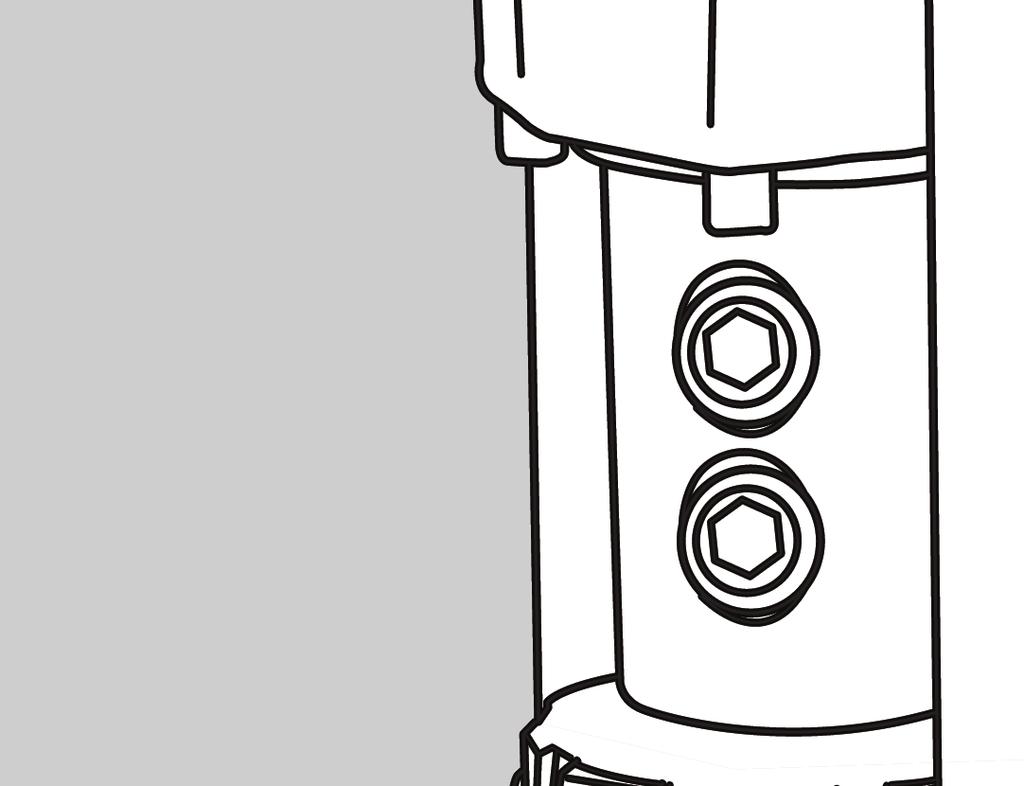
8 Set Screws -/" Diam. Shank Rotabroach Cutter INSTALLING CUTTER Spindle Spindle Adapter Set Screw 3/" Diam. Shank Rotabroach Cutter OPERATION OF CUTTING FLUID RESERVOIR When everything is ready to go (Magnet ON and Impactors seated), open the Adjustment Needle to provide a generous fl ow of cutting fl uid until a puddle approximately the diameter of the cutter being used is developed on the workpiece. Once this initial supply of cutting fl uid is established on the workpiece, adjust the fl ow to a steady drip. HINTS FOR SMOOTHER OPERATION Ejector Rod Point. Jog motor until appropriate set screws are accessible. 2. Either lay drill on its side with feed wheel up, or be sure Spindle sure Spindle clears table if unit is in normal operation position. 3. A) Hougen Cutters with -/" dia. shanks Loosen the two short set screws and cutter shank being certain that the fl ats are aligned with the set screw holes. Tighten the lower set screw fi rst and then tighten the upper set screw. (Be sure the long set screw on opposite side of spindle has been removed. B) Hougen Cutters with 3/" dia. shanks Install the spindle adapter using the same procedure as used when mounting cutters with -/" diameter shanks. Slip the Cutter Shank into the adapter so that the fl at on its shank is aligned with the single set screw hole. Install the long set screw and tighten.. Keep inside of Hougen Cutter clear of chips.chips will interfere with cutting to maximum depth, may impede the free fl ow of cutting fl uid and can cause cutter breakage. 2. Keep work, machine, arbor and Hougen Cutter free of chips and dirt. 3. Tighten all fasteners periodically.. We highly recommend using a light cutting fl uid (preferbly Hougen Cutting Fluid) 5. Occasionally check metering of cutting fl uid fl ow. Lack of cutting fl uid may cause Hougen Cutter to freeze in cut, slug to stick and may result in poor cutter life. 6. Always start cut with light feed pressure and then increase suffi ciently to achieve maximumcutting rate. 7. Ease off on pressure as cutter begins to break through at end of cut. 8. When slug hangs up in cutter, bring cutter down on a fl at surface. This will normally straighten a cocked slug, allowing it to be ejected. 9. Cut overlapping holes using minimum steady pressure. (External lubrication should be used) Note: When cutting in this manner, cutting fluid may escape from cutting area. Tool should be fed with care, using external lubrication C) "2,000-Series" Shanks When using "2,000-Series" shank cutters, DO NOT us the long set screws. Install cutter adapter using the two small set screws lining up the two fl ats. Install adapter into quill and secure using set screws.. Check periodically during operation to be certain that the cutter is secure. 8
9 20V PANEL COMPONENTS 6 No. Part # Description Qty OFF BLK. 2 3 OFF + ON + - BLK. 2 ON Nut # Faceplate Relay - Solid State 0703 Pilot Light Rectifier Toggle Switch Magnet Surge Suppressor Push Button SwitchGuard Motor "ON" Switch Motor "OFF" Switch 096 Toggle Switch Guard Relay Logic V Panel Assy. * 0766 Circuit Breaker * 008 Wire Harness English * Not Shown V HOOK UP DIAGRAM Circuit Breaker Power Cord (Black) Safety Switch (White) Jumper Magnet (Red) Magnet (Orange) Power Cord (White) Safety Switch (Black) Motor (Red or White) Motor (Black) Ground (Green) Attach under motor screw 9
10 230V PANEL 23 COMPONENTS No. 26 Part # Description Qty Nut # Faceplate Relay - Solid State Pilot Light OFF 3 BLK. 2 ON Rectifier Toggle Switch Magnet Surge Suppressor Push Button SwitchGuard Motor "ON" Switch Motor "OFF" Switch Toggle Switch Guard Relay Logic 20 3 OFF BLK. 2 ON V Panel Assy. * 0785 Circuit Breaker * 008 Wire Harness * Not Shown V HOOK UP DIAGRAM Circuit Breaker Power Cord (Black) Safety Switch (White) Jumper Magnet (Red) Magnet (Orange) Power Cord (White) Safety Switch (Black) Motor (Red or White) Motor (Black) Ground (Green) Attach under motor screw 0
11 MOTOR PARTS English Motor Assembly 20V 0896 Motor Assembly 230V Item Part # Description Qty Item Part # Description Qty 08 SCR-SHC #0-32 x -/ Assembly Gears #2 & # Washer - Lock Helical # Gear Box Cover Retaining Ring Washer - Spring 027 Bearing 25MM x 7MM x 2MM Armature Assembly - 20V SCR-SHSLD 3/6 x 7/ Armature Assembly - 230V Switch SCR-SHC #0-32 x 3-/2 LG Spring-Comp Baffle Gear Box Housing Field - 20V Spindle- Motor Drive 0800 Field - 230V Key Motor Brush Holder Assembly Gear Spur Removable Specs Label - 20V Retaining Ring Specs Label - 230V Ball Bearing Motor Label Gear Spur Removable Brush Holder Cap Key Carbon Brushes Shift Control Rod Arm Strain Relief Assembly, Change gear Cover, Brush Access Washer - Flat 8MM SCR-BHC #6-32 x / Needle Bearing Washer - Lock
12 HMD933 Exploded View * 9* 8* a* * 2* 3* * * Included in 026 Assembly
13 Adapter for "2,000-Series" Cutters English
14 HMD933 PARTS BREAKDOWN No. Part # Description Qty 026 Bottle Assembly 026 Cap (Must buy Bottle Assy) Hold Down Fitting Washer 02 Bottle Block (Must buy Bottle Assy) 5a 025 Drip Tube SHCS /2-3 x Washer / Adjustment Needle 9 02 O-Ring Screw /-20 x / Tie Bar SHCS /-20 x -/ Feed Rod Hex Nut 7/ Knurled Nut 7/ Ejector Rod 7 0 Ejector Rod Point SHCS 5/6-8 x 3/ Lock Washer 5/ Strut Assy 2 07 Grommet 27 0 SCR-SOC Set 5/8- x / Spring Plunger SCR-SHC 5/6-8 x 2-/ SCR-SHC 5/6-8 x -/ Strain Relief SCR-BHC /-20 x / Washer 5/6 Flat Nut 5/6-8 UNC Washer Lock /2 Hel 0 0 SCR-SHC /2-3 x -/ SCR-BHC # Safety Switch Assy Bracket-Safety Switch Shield-Safety Switch No. Part # Description Qty SCR-SHC /-20 x / SCR-SS /-20 x 3/8 BR Magnet 230V Magnet 5V Spring Plunger Assy Base Plate Seal 7/ Bushing 7/ Main Housing SCR-SHC /-28 x 7/ Retaining Ring Washer 9/6 x -3/ Gear Spur 6 teeth Key Bushing 9/ Bushing 7/ Retaining Ring Thrust Washer Bearing 7/ Handle Assy Bushing Washer 7/ Gear Spindle 36 Teeth 8 08 Spacer - Spindle Bearing 3/ Gear Idler 32 Teeth Change Gear 8 Teeth 006 Change Gear 30 Teeth Idler Shaft Bearing Bearing Seal 3/ x Retaining Ring Lower Grease Fitting Washer Altered Shaft-Spline
15 HMD933 PARTS BREAKDOWN No. Part # Description Qty Driven Gear 6 Teeth Thrust Washer SHCS 0-32 x 5/ Washer # Upper Retaining Ring Electrical Box V Motor V Motor Circuit Breaker 5A - 20V 0785 Circuit Breaker 8A - 230V Grommet SCR-BHC / Panel Assy - 20V 038 Panel Assy - 230V 070 SCR- # Power Cord 20V Power Cord 230V Power Cord 230V Type I Hub - Feed Shaft Assy 0569 Feed Handle Feed Handle Knob Cord No. Part # Description Qty O-Ring Dowel Pin / Housing Spindle Bearing Lower Bearing Cap Assy SCR-SHC /-20 x -/ SCR-SHC /-20 x SCR-SHC /-20 x 2-/ Retaining Ring Spindle Key 3/ SCR-SS 3/-0 Alt Chip Guard Retaining Ring SCR-SS /-20 x / BR Washer / Lock Washer Adapter Tag - Gear Chart #2 Drive Screw Label - Safety Instructions Label - 20V Bearing 0 08 Bracket Electrical Box English 5
16 COMMERCIAL / INDUSTRIAL LIMITED WARRANTY Hougen Manufacturing, Incorporated warrants its Portable Magnetic Drills and its Electro-hydraulic Hole Punchers for a period of year and other products for ninety (90) days from date of purchase against defects due to faulty material or workmanship and will repair or replace (at its option) without charge any items returned. This warranty is void if the item has been damaged by accident or unreasonable use, neglect, improper service, or other causes not arising out of defects in material or workmanship. No other expressed warranty is given or authorized. Hougen Manufacturing, Inc. disclaims any implied warranty of MERCHANTABILITY or FITNESS for any period beyond the expressed warranty and shall not be liable for incidental or consequential damages. Some states do not allow exclusions of incidental or consequential damages or limitation on how long an implied warranty lasts and, if the law of such a state governs your purchase, the above exclusion and limitation may not apply to you. This warranty gives you specific legal rights and you may also have other rights which vary from state to state. To obtain warranty service: return the item(s), transportation prepaid, to your nearest Factory Authorized Warranty Repair Center or to Hougen Manufacturing, Inc., 300 Hougen Drive, Swartz Creek, Michigan 873. Hougen Drills are warranted against manufacturing defects only. Subject to Hougen Manufacturing inspection. THIS WARRANTY IS IN LIEU OF ANY OTHER WARRANTY, EXPRESSED OR IMPLIED, INCLUDING ANY WARRANTY OF MERCHANTABILITY OR FITNESS FOR A PARTICULAR PURPOSE. 20 Hougen Manufacturing, Inc. Photographs and Specifications shown are accurate in detail at time of printing. Manufacturer reserves the right to make improvements and modifications without prior notice. Hougen, Rotabroach, and Hougen-Edge are proprietary trademarks of Hougen Manufacturing Inc. HOUGEN AUTHORIZED WARRANTY REPAIR CENTERS Hougen Authorized Warranty Repair Centers have been factory trained to properly service and repair Hougen Portable Magnetics Drills. To locate an Authorized Warranty Repair Centers near you, please visit: Hougen Manufacturing, Inc. P.O. Box 2005 Flint, MI Hougen Drive Swartz Creek, MI 873 Phone (80) Fax (80) info@hougen.com 20 Hougen Manufacturing, Inc. 6
PORTABLE MAGNETIC DRILLS
 HMD914 SERIES PORTABLE MAGNETIC DRILLS COVERS DRILL PART NUMBER 0914102 FOR USE WITH 12,000-SERIES HOUGEN CUTTERS HOUGEN Portable Magnetic Drills Models HMD914 Welcome to Hougen Congratulations on your
portable magnetic drills
 HMD115 series portable magnetic drills operator s manual COVERS DRILL MODEL 0115201, 0115301 & 0115401 for use with Rotaloc cutters OM1151014 Printed in U.S.A. HOUGEN Portable Magnetic Drill Welcome to
MODEL HMD150 SERIES PORTABLE MAGNETIC DRILLS OPERATOR S MANUAL COVERS DRILL PART NUMBERS , & FOR USE WITH ROTALOC PLUS CUTTERS
 MODEL HMD50 SERIES PORTABLE MAGNETIC DRILLS OPERATOR S MANUAL COVERS DRILL PART NUMBERS 05020, 05030 & 05040 FOR USE WITH ROTALOC PLUS CUTTERS HOUGEN Welcome to Hougen PORTABLE MAGNETIC DRILL Congratulations
portable magnetic drills
 model HMD150 Series portable magnetic drills operator s manual COVERS DRILL PART NUMBERS 0150101 for use with Rotaloc plus cutters OM1500216CSA Printed in U.S.A. HOUGEN Welcome to Hougen Portable Magnetic
PORTABLE MAGNETIC DRILLS
 MODEL HMD115 SERIES PORTABLE MAGNETIC DRILLS OPERATOR S MANUAL COVERS DRILL MODEL 0115101 FOR USE WITH ROTALOC CUTTERS HOUGEN PORTABLE MAGNETIC DRILL Welcome to Hougen Congratulations on your purchase
MODEL HMD150 SERIES OPERATOR S MANUAL
 MODEL HMD150 SERIES PORTABLE MAGNETIC DRILLS OPERATOR S MANUAL COVERS DRILL PART NUMBERS 0150201, 0150301 & 0150401. FOR USE WITH ROTALOC PLUS CUTTERS HOUGEN Welcome to Hougen PORTABLE MAGNETIC DRILL Congratulations
portable magnetic drills
 model HMD50 Series portable magnetic drills operator s manual COVERS DRILL PART NUMBERS 05020, 05030 & 05040 for use with Rotaloc plus cutters OM50026 Printed in U.S.A. HOUGEN Welcome to Hougen Portable
roto-kut frame drill
 operator s manual portable magnetic drills Part No. 82-4427 roto-kut frame drill For Use with ROTO-KUT Frame Cutters roto-kut frame drill Part No. 82-4427 Welcome to Kimball Midwest Congratulations on
HMD505 SERIES PORTABLE MAGNETIC DRILL OPERATOR S MANUAL COVERS DRILL PART NUMBERS , &
 HMD505 SERIES PORTABLE MAGNETIC DRILL OPERATOR S MANUAL COVERS DRILL PART NUMBERS 0505102, 0505202 & 0505402 FOR USE WITH HOUGEN 12,000-SERIES CUTTERS HOUGEN Portable Magnetic Drill Model HMD505 Welcome
HMD501 PORTABLE MAGNETIC DRILL
 HMD501 PORTABLE MAGNETIC DRILL OPERATOR S MANUAL COVERS DRILL PART NUMBER 0501302 FOR USE WITH 12,000-SERIES HOUGEN CUTTERS HOUGEN Portable Magnetic Drill Model HMD501 Welcome to Hougen Congratulations
HMD904 PORTABLE MAGNETIC DRILL OPERATOR S MANUAL
 HMD904 PORTABLE MAGNETIC DRILL OPERATOR S MANUAL FOR USE WITH 12,000-SERIES HOUGEN CUTTERS HOUGEN Portable Magnetic Drill Model HMD904 Welcome to Hougen Congratulations on your purchase of the Hougen Portable
HMD914 & HMD914S PORTABLE MAGNETIC DRILLS
 HMD914 & HMD914S PORTABLE MAGNETIC DRILLS OPERATOR S MANUAL FOR USE WITH 12,000-SERIES HOUGEN CUTTERS HOUGEN Portable Magnetic Drills Models HMD914 & HMD914S Welcome to Hougen Congratulations on your purchase
HOUGEN HMD505 EXPLODED VIEW , , &
 HOUGEN HMD0 EXPLODED VIEW 000, 000, 000 & 000 0, The 000 is assembled with a Type I Plug. The 000 is assembled without an electrical plug at the end of the power cord. a c 0 b,0 0 End Panel Assembly 0v
HMD904 SERIES PORTABLE MAGNETIC DRILL OPERATOR S MANUAL COVERS DRILL PART NUMBER , , , , &
 HMD904 SERIES PORTABLE MAGNETIC DRILL OPERATOR S MANUAL COVERS DRILL PART NUMBER 090420, 0904202, 090403, 0904203, 090404 & 0904204 FOR USE WITH 2,000-SERIES HOUGEN CUTTERS HOUGEN Portable Magnetic Drill
HMD925 POWER FEED MAGNETIC DRILL
 HMD925 POWER FEED MAGNETIC DRILL OPERATOR S MANUAL FOR USE WITH 12,000-SERIES HOUGEN CUTTERS HOUGEN Portable Magnetic Drill Model HMD925 Welcome to Hougen Congratulations on your purchase of the Hougen
operator s manual HMD918 SERIES PORTABLE MAGNETIC DRILL
 operator s manual HMD918 SERIES PORTABLE MAGNETIC DRILL Covers Drill Part Numbers: 0918102 OM9180717EF Printed in U.S.A. HOUGEN PORTABLE MAGNETIC DRILL MODEL HMD918 SERIES Welcome to Hougen Congratulations
HMD505 PORTABLE MAGNETIC DRILL OPERATOR S MANUAL FOR USE WITH 12,000-SERIES ROTABROACH
 HMD505 PORTABLE MAGNETIC DRILL OPERATOR S MANUAL FOR USE WITH,000-SERIES ROTABROACH CUTTERS HOUGEN Portable Magnetic Drill Model HMD505 Welcome to Hougen Congratulations on your purchase of the Hougen
HMD904S PORTABLE MAGNETIC DRILL
 HMD904S PORTABLE MAGNETIC DRILL OPERATOR S MANUAL PATENT PENDING FOR USE WITH 12,000-SERIES HOUGEN CUTTERS HOUGEN Portable Magnetic Drill Model HMD904S Welcome to Hougen Congratulations on your purchase
MODELS &10914S PORTABLE MAGNETIC DRILLS OPERATOR S MANUAL FOR USE WITH 12,000-SERIES HOUGEN CUTTERS
 MODELS 10914 &10914S PORTABLE MAGNETIC DRILLS OPERATOR S MANUAL FOR USE WITH 12,000-SERIES HOUGEN CUTTERS HOUGEN Portable Magnetic Drills Models 10914 & 10914S Welcome to Hougen Congratulations on your
operator s manual HMD905 SERIES PORTABLE MAGNETIC DRILL
 operator s manual HMD905 SERIES PORTABLE MAGNETIC DRILL Covers Drill Part Numbers: 09050 090504 090530 0905304 090540 090540 OM9050717BEF Printed in U.S.A. HOUGEN PORTABLE MAGNETIC DRILL MODEL HMD905 SERIES
HMD904 PORTABLE MAGNETIC DRILL OPERATOR S MANUAL FOR USE WITH 12,000-SERIES HOUGEN
 HMD904 PORTABLE MAGNETIC DRILL OPERATOR S MANUAL FOR USE WITH,000-SERIES HOUGEN CUTTERS HOUGEN Portable Magnetic Drill Model HMD904 Welcome to Hougen Congratulations on your purchase of the Hougen Portable
E-DRIV MD-Series DC Torque Control System Calibration Procedure
 Revision: 1.1 July 05, 2017 E-DRIV MD-Series DC Torque Control System Calibration Procedure www.mountztorque.com 1080 N 11 th St - San Jose CA 95112-408.292.2214 1 GENERAL SAFETY RULES WARNING! Read and
CONTROL PANEL PARTS. Part # Description Qty. Part # Description Qty Momentary Switch Push Button Guard 1.
 CONTROL PANEL PARTS MAGNET 7 A M P MOTOR PRESS-ON OFF / ON RELEASE- OFF 04437 17575 04644 17032 17552 04438 04449 AUS 17035 01226 17049 BLACK POWER 01835 WHITE POWER 17048 17041 MOTOR WHITE MOTOR BLACK
CONTROL PANEL PARTS. Part # Description Qty. Part # Description Qty Momentary Switch Push Button Guard Rocker Switch 1
 CONTROL PANEL PARTS MAGNET 7 A M P MOTOR PRESS-ON OFF / ON RELEASE- OFF 01833 17575 17032 04644 17034 17545 17035 01226 17049 BLACK POWER 01835 WHITE POWER 17048 MOTOR WHITE MOTOR BLACK Part # Description
TABLE OF CONTENTS. Section 1 - Important Safety Instructions Section 2 - Grounding Instructions Section 3 - Operator Cautions...
 Light Tools - DC Screwdriver Operation & Maintenance Manual For Models: SKD-2000L/UL/B, SKD-2200L/UL/B, SKD-2300L/UL/B SKD-5200L/UL/B, SKD-5200P/UL/B SKD-5300L/UL/B, SKD-5300P/UL/B Dixon Automatic Tool
PUNCH PRO ELECTRO-HYDRAULIC HOLE PUNCHER OPERATOR S MANUAL
 PUNCH PRO ELECTRO-HYDRAULIC HOLE PUNCHER OPERATOR S MANUAL Model 75004A IMPORTANT SAFETY INSTRUCTIONS WARNING: When using electric tools, basic safety precautions should always be followed to reduce the
Instructions manual / Position Controller 1. GY-G Series INSTRUCTIONS MANUAL
 Instructions manual / Position Controller 1 GY-G Series INSTRUCTIONS MANUAL Instructions manual / GY-G Series 2 IMPORTANT The tool delivered with this manual may been modified for specific needs. In that
4-VOLT LITHIUM-ION AUTO-LOAD SCREWDRIVER w/led WORKLIGHT
 SKU 241-1394 4-VOLT LITHIUM-ION AUTO-LOAD SCREWDRIVER w/led WORKLIGHT Operation Manual WARNING! Please read this manual before using this product. Failure to do so can result in serious injury. SAVE THIS
Model TC-20. Tube Cut-Off Machine. Operator s Manual REV H
 Model TC-20 Tube Cut-Off Machine Operator s Manual 90-2333 REV H Scientific Systems, Inc. 349 N. Science Park Road State College, PA 16803 www.ssihplc.com Phone: 800-441-4752 Fax: 814-238-7532 Email: sales@ssihplc.com
BUFFER/POLISHER SYSTEM
 Owner s Manual Double Insulated BUFFER/POLISHER SYSTEM Model No. 646.10729 NRTL CAUTION: Read and follow all safety rules and operating instructions before first use of this product. Safety Rules Operation
SBC12 H Operating instructions Mode d emploi Manual de instrucciones
 *254901* 254901 SBC12 H Operating instructions Mode d emploi Manual de instrucciones Safety Precautions Read all Instructions GENERAL SAFETY RULES FOR ALL BATTERY OPERATED TOOLS WARNING! Read and understand
OPERATING INSTRUCTIONS. Note: 6V Charging. Requires Manual Shut Off.
 Requires Manual Shut Off. 6 / 2 AMP,, DUAL RATE BATTER TTERY CHARGER 45005 OPERATING INSTRUCTIONS E224783 E224783 Note: 6V Charging Due to continuing improvements, actual product may differ slightly from
WR 22SE WR 25SE WR25SE. Handling instructions
 WR 22SE WR 25SE WR25SE Handling instructions GENERAL POWER TOOL SAFETY WARNINGS WARNING Read all safety warnings and all instructions. Failure to follow the warnings and instructions may result in electric
W6VB3 W8VB2. Handling instructions
 Screw Driver Model W 6VM W 6V4 W 6VA4 W 6VB3 W 8VB2 Handling instructions W6VM W6V4 W6VA4 W6VB3 W8VB2 Note: Before using this Electric Power Tool, carefully read through these HANDLING INSTRUCTIONS to
1200W Paint DRYING Lamp
 1200W Paint DRYING Lamp Model 97641 Assembly And Operation Instructions Diagrams within this manual may not be drawn proportionally. Due to continuing improvements, actual product may differ slightly from
75006 PUNCH PRO ELECTRO-HYDRAULIC HOLE PUNCHER operator s manual COVERS HOLE PUNCHER PART NUMBERS &
 75006 PUNCH PRO ELECTRO-HYDRAULIC HOLE PUNCHER operator s manual COVERS HOLE PUNCHER PART NUMBERS 07561 & 0756201 IMPORTANT SAFETY INSTRUCTIONS WARNING: When using electric tools, basic safety precautions
BENCH GRINDER MODEL NO. OZBG150WA
 BENCH GRINDER 150mm MODEL NO. OZBG150WA OPERATING INSTRUCTIONS To view our entire range visit www.ozito.com.au SPECIFICATIONS MODEL NO. OZBG150WA Input Power: 150W Input Voltage: 230V ~ 50Hz No Load Speed:
RMT1201. ORIGINAL INSTRUCTIONS Cordless Multi-Tool
 RMT1201 ORIGINAL INSTRUCTIONS Cordless Multi-Tool Important! It is essential that you read the instructions in this manual before operating this machine. Subject to technical modifications. Safety GENERAL
REED MANUFACTURING COMPANY
 Catalog No. - 700APD Item Code #05260 700APD Power Drive The REED 700APD Power Drive is a portable, pneumatic-motor-driven, heavy-duty power drive which provides power for threading pipe and conduit up
1200W CaR PoliSheR en RS4900
 1200W Car Polisher RS4900 RS4900 8 1 2 7 3 4 5 6 A B flat nozzle C D E F 1200W Car Polisher RS4900 G H flat nozzle I J K L 4 1200W Car Polisher COMPONT LIST 1 2 3 4 5 6 7 Variable speed control Switch
75005 PUNCH PRO ELECTRO-HYDRAULIC HOLE PUNCHER operator s manual COVERS HOLE PUNCHER PART NUMBERS &
 75005 PUNCH PRO ELECTRO-HYDRAULIC HOLE PUNCHER operator s manual COVERS HOLE PUNCHER PART NUMBERS 07551 & 755201 IMPORTANT SAFETY INSTRUCTIONS WARNING: When using electric tools, basic safety precautions
HYDRAULIC ROLL GROOVING ATTACHMENT 1/2-12
 HYDRAULIC ROLL GROOVING ATTACHMENT 1/2-12 Read this Operator s Manual carefully before using this tool. Failure to understand and follow the contents of this manual may result in electrical shock, fire
SPECIFICATIONS GENERAL SAFETY RULES PERSONAL SAFETY. Save This Manual TOOL USE AND CARE WORK AREA
 SPECIFICATIONS 2 Forged Safety Latch Hooks Cable extends to: 44 Drop forged steel hanging bracket Heavy duty 3/16 Steel Cable Pulling Capacity: 1200 LB. One piece double ratchet gear Save This Manual You
Angle Grinder Holder
 Angle Grinder Holder Owner s Manual WARNING: Read carefully and understand all ASSEMBLY AND OPERATION INSTRUCTIONS before operating. Failure to follow the safety rules and other basic safety precautions
MINI AIR ANGLE DIE GRINDER
 MINI AIR ANGLE DIE GRINDER Model 33171 ASSEMBLY AND OPERATING INSTRUCTIONS Due to continuing improvements, actual product may differ slightly from the product described herein. 3491 Mission Oaks Blvd.,
4V LITHIUM-ION SCREWDRIVER OWNER S OPERATING MANUAL
 CSD-4107BG 4V LITHIUM-ION SCREWDRIVER OWNER S OPERATING MANUAL Your screwdriver has been engineered and manufactured to our high standard for dependability, ease of operation, and operator safety. When
Hot-Shot Operating Instructions
 Hot-Shot Operating Instructions Model 400, 320, and 300 (For use with Copper and Iron Pipe) Your Hot-Shot is designed to give you years of trouble-free, profitable service. However, no machine is better
original instructions 18V Torch RFP1801
 original instructions 18V Torch RFP1801 Important! It is essential that you read the instructions in this manual before operating this machine. Subject to technical modifications. Safety GENERAL POWER
Push Trolley. Owner s Manual
 Push Trolley Owner s Manual WARNING: Read carefully and understand all ASSEMBLY AND OPERATION INSTRUCTIONS before operating. Failure to follow the safety rules and other basic safety precautions may result
Manual Chain Hoist. Owner s Manual
 Manual Chain Hoist Owner s Manual WARNING: Read carefully and understand all ASSEMBLY AND OPERATION INSTRUCTIONS before operating. Failure to follow the safety rules and other basic safety precautions
WR 16SE. de fr it nl es pt sv da no fi el pl hu cs tr ro sl sk bg sr hr uk ru. Handling instructions
 en WR 16SE de fr it nl es pt sv da no fi el pl hu cs tr ro sl sk bg sr hr uk ru Handling instructions GENERAL POWER TOOL SAFETY WARNINGS WARNING Read all safety warnings and all instructions. Failure to
3-Pt. Quick Hitch. Owner s Manual
 3-Pt. Quick Hitch Owner s Manual WARNING: Read carefully and understand all ASSEMBLY AND OPERATION INSTRUCTIONS before operating. Failure to follow the safety rules and other basic safety precautions may
Heavy-Duty Drywall Dolly Cart
 Heavy-Duty Drywall Dolly Cart Owner s Manual WARNING: Read carefully and understand all ASSEMBLY AND OPERATION INSTRUCTIONS before operating. Failure to follow the safety rules and other basic safety precautions
TWIN HALOGEN SHOP LIGHT
 TWIN HALOGEN SHOP LIGHT 36787 ASSEMBLY & OPERATING INSTRUCTIONS 3491 Mission Oaks Blvd., Camarillo, CA 93011 Visit our Web Site at www.harborfreight.com Copyright 2005 by Harbor Freight Tools. All rights
Electric Chainsaw Sharpener With Bar Mount
 Electric Chainsaw Sharpener With Bar Mount Owner s Manual WARNING: Read carefully and understand all ASSEMBLY AND OPERATION INSTRUCTIONS before operating. Failure to follow the safety rules and other basic
SeekTech Inductive Clamp
 Inductive Clamp Manual SeekTech Inductive Clamp! Read this Operator s Manual carefully before using this tool. Failure to understand and follow the contents of this manual may result in electrical shock,
eclipse Instruction Manual 4.0V Li-Ion Screwdriver Part #:
 eclipse Instruction Manual 4.0V Li-Ion Screwdriver Part #: 902-588 Test Equipment Depot - 800.517.8431-99 Washington Street Melrose, MA 02176 TestEquipmentDepot.com Test Equipment Depot - 800.517.8431-99
CAMBELT TENSION GAUGE
 CAMBELT TENSION GAUGE Model 96557 Operating Instructions Diagrams within this manual may not be drawn proportionally. Due to continuing improvements, actual product may differ slightly from the product
Angle Grinder INSTRUCTION MANUAL. 180 mm (7 ) MODEL 9077SL 6,000. No load speed irpm) 484 mm (1 9 ) 5.3 kg (1 1.6 Ibs) 5/8-11 UNC
 MODEL 9077SL 6,000. No load speed irpm) 484 mm (1 9 ) 5.3 kg (1 1.6 Ibs) 5/8-11 UNC") Angle Grinder 180 mm (7 ) MODEL 9077SL NSTRUCTON MANUAL No load speed irpm) 6,000 Overall length Net weight Spindle thread 484 mm (1 9 ) 5.3 kg (1 1.6 bs) 5/8-11 UNC GENERAL SAFETY RULES (For All Tools)
Angle Grinder 180 mm (7 ) MODEL 9077SL NSTRUCTON MANUAL No load speed irpm) 6,000 Overall length Net weight Spindle thread 484 mm (1 9 ) 5.3 kg (1 1.6 bs) 5/8-11 UNC GENERAL SAFETY RULES (For All Tools)
ECSS. Electric Chain Saw Chain Sharpener Assembly & Operating Instructions
 ECSS Electric Chain Saw Chain Sharpener Assembly & Operating Instructions READ ALL INSTRUCTIONS AND WARNINGS BEFORE USING THIS PRODUCT. SAVE THESE INSTRUCTIONS FOR FUTURE REFERENCE. This manual provides
MOTOR PARTS DIAGRAM. Wires to Motor. Cord
 17625 17627 17605 17624 17614 17611 05462 17612 MOTOR PARTS DIAGRAM 17601 17609 17626 17608 17618 17613 17603 17602 17607 17610 17617 17628 Wires to Motor Cord 17623 17606 17602 17604 17600 17630 17632
Instruction Manual. CORDLESS DRILL 18V Li-ion WITH IMPACT FUNCTION. Model SROM 1172
 Instruction Manual CORDLESS DRILL 18V Li-ion WITH IMPACT FUNCTION Model SROM 1172 Our tool range has you covered for DIY. Whatever the job, make light work of it with MAKO tools. Product Features: 1. Keyless
Sawhorse with Chainsaw Holder
 Sawhorse with Chainsaw Holder Owner s Manual Chainsaw not included. WARNING: Read carefully and understand all ASSEMBLY AND OPERATION INSTRUCTIONS before operating. Failure to follow the safety rules and
Large Hydraulic Bead Breaker
 Large Hydraulic Bead Breaker Owner s Manual WARNING: Read carefully and understand all ASSEMBLY AND OPERATION INSTRUCTIONS before operating. Failure to follow the safety rules and other basic safety precautions
Compressor Duty Motor - 1 HP. Model 40132
 Compressor Duty Motor - 1 HP Model 40132 Assembly and Operating Instructions 3491 Mission Oaks Blvd., Camarillo, CA 93011 Visit our web site at http://www.harborfreight.com Copyright 2002 by Harbor Freight
60 Watt Industrial LED Low Bay Light
 60 Watt Industrial LED Low Bay Light Owner s Manual WARNING: Read carefully and understand all ASSEMBLY AND OPERATION INSTRUCTIONS before operating. Failure to follow the safety rules and other basic safety
INSTRUCTION MANUAL ANGLE GRINDER PT W
 INSTRUCTION MANUAL ANGLE GRINDER PT50360 4½ INCHES 120V 60Hz 600W 5A 12,000 rpm C US Note : Before operating this tool, read this manual and follow all safety rules and operating instructions. This electric
8 Inch Benchtop Buffer
 8 Inch Benchtop Buffer Owner s Manual WARNING: Read carefully and understand all ASSEMBLY AND OPERATION INSTRUCTIONS before operating. Failure to follow the safety rules and other basic safety precautions
Welding Clips. Model Due to continuing improvements, actual product may differ slightly from the product described herein.
 Welding Clips Model 95637 Assembly And Operation Instructions Due to continuing improvements, actual product may differ slightly from the product described herein. 3491 Mission Oaks Blvd., Camarillo, CA
Electric Chainsaw Sharpener
 Electric Chainsaw Sharpener Owner s Manual WARNING: Read carefully and understand all ASSEMBLY AND OPERATION INSTRUCTIONS before operating. Failure to follow the safety rules and other basic safety precautions
Heavy-Duty Welding Fabrication Table
 Heavy-Duty Welding Fabrication Table with Fix-Up Kit Owner s Manual WARNING: Read carefully and understand all ASSEMBLY AND OPERATION INSTRUCTIONS before operating. Failure to follow the safety rules and
Adjustable Steel Welding Table
 Adjustable Steel Welding Table Owner s Manual WARNING: Read carefully and understand all ASSEMBLY AND OPERATION INSTRUCTIONS before operating. Failure to follow the safety rules and other basic safety
Garden Hose Reel with 3/4In. x 100Ft. Hose. Owner s Manual
 Garden Hose Reel with 3/4In. x 100Ft. Hose Owner s Manual WARNING: Read carefully and understand all ASSEMBLY AND OPERATION INSTRUCTIONS before operating. Failure to follow the safety rules and other basic
Telescoping Pressure Washer Wand 18'
 Telescoping Pressure Washer Wand 18' Owner s Manual WARNING: Read carefully and understand all ASSEMBLY AND OPERATION INSTRUCTIONS before operating. Failure to follow the safety rules and other basic safety
50 Ft. Retractable Cord Reel
 50 Ft. Retractable Cord Reel with Triple Tap Owner s Manual WARNING: Read carefully and understand all ASSEMBLY AND OPERATION INSTRUCTIONS before operating. Failure to follow the safety rules and other
ELECTRIC CAR POLISHER
 ELECTRIC CAR POLISHER MODEL NO: CP254 PART NO: 6462108 OPERATION & MAINTENANCE INSTRUCTIONS LS0610 INTRODUCTION Thank you for purchasing this CLARKE electric car polisher. Before attempting to use this
Manual Tire Changing Station
 Manual Tire Changing Station Owner s Manual WARNING: Read carefully and understand all ASSEMBLY AND OPERATION INSTRUCTIONS before operating. Failure to follow the safety rules and other basic safety precautions
VICE MOUNTED BEAD ROLLER
 VICE MOUNTED BEAD ROLLER Owner s Manual WARNING: Read carefully and understand all ASSEMBLY AND OPERATION INSTRUCTIONS before operating. Failure to follow the safety rules and other basic safety precautions
SAFETY AND OPERATING MANUAL. Lithium-Ion cordless hammer drill WX372 WX372.1 WX372.9
 SAFETY AND OPERATING MANUAL 2 Original Instructions General Power Tool Safety Warnings WARNING: Read all safety warnings and all instructions. Failure to follow the warnings and instructions may result
AIR PAINT SHAKER OWNER'S MANUAL
 AIR PAINT SHAKER OWNER'S MANUAL WARNING: Read carefully and understand all INSTRUCTIONS before operating. Failure to follow the safety rules and other basic safety precautions may result in serious personal
ANGLE DIE GRINDER KIT
 ANGLE DIE GRINDER KIT Model 93157 ASSEMBLY AND OPERATING INSTRUCTIONS Due to continuing improvements, actual product may differ slightly from the product described herein. 3491 Mission Oaks Blvd., Camarillo,
DISC BRAKE CALIPER TOOL SET
 DISC BRAKE CALIPER TOOL SET 40732 ASSEMBLY AND OPERATING INSTRUCTIONS Diagrams within this manual may not be drawn proportionally. Due to continuing improvements, actual product may differ slightly from
Hydraulic Bead Breaker Kit
 Hydraulic Bead Breaker Kit Owner s Manual WARNING: Read carefully and understand all ASSEMBLY AND OPERATION INSTRUCTIONS before operating. Failure to follow the safety rules and other basic safety precautions
Inductive. SeekTech Clamp WARNING! Operator s Manual
 99 Washington Street Melrose, MA 02176 Phone 781-665-1400 Toll Free 1-800-517-8431 Visit us at www.testequipmentdepot.com SeekTech Clamp Inductive Operator s Manual WARNING! Read this operator s manual
Auto-Locking Pintle Hook
 Auto-Locking Pintle Hook 7-Ton Capacity Owner s Manual WARNING: Read carefully and understand all ASSEMBLY AND OPERATION INSTRUCTIONS before operating. Failure to follow the safety rules and other basic
Mini Lever Hoist. Owner s Manual
 Mini Lever Hoist Owner s Manual WARNING: Read carefully and understand all ASSEMBLY AND OPERATION INSTRUCTIONS before operating. Failure to follow the safety rules and other basic safety precautions may
INSTRUCTION MANUAL. Cordless Angle Drill XAD01
 INSTRUCTION MANUAL Cordless Angle Drill XAD0 0474 ENGLISH (Original instructions) SPECIFICATIONS Model XAD0 Capacities Steel 0 mm (3/8") Wood 25 mm (") No load speed (RPM) 0 -,800 /min Overall length 34
SAFETY RULES SPECIFICATIONS READ ALL INSTRUCTIONS BEFORE OPERATING SAVE THESE INSTRUCTIONS
 READ ALL INSTRUCTIONS BEFORE OPERATING SAVE THESE INSTRUCTIONS Thank you for purchasing 7" Polisher. Before attempting to operate your new Polisher please read these instructions thoroughly. You will need
RPS1215 ORIGINAL INSTRUCTIONS. Cordless Pruner
 RPS5 ORIGINAL INSTRUCTIONS Cordless Pruner Important! It is essential that you read the instructions in this manual before assembling, operating and maintaining the product. Subject to technical modification.
FJC, Inc. Part # V BATTERY Charger/Maintainer INSTRUCTION MANUAL SAFETY WARNINGS AND PRECAUTION
 FJC, Inc. Part # 52020 12V BATTERY Charger/Maintainer INPUT: 110V AC 60Hz OUTPUT: 6/12V DC 2A INSTRUCTION MANUAL SAFETY WARNINGS AND PRECAUTION CAUTION: TO PREVENT BATTERY DAMAGE: DO NOT USE on gel batteries
24 Volt - 3/8" Cordless Impact Wrench
 24 Volt - 3/8" Cordless Impact Wrench INSTRUCTION MANUAL Item # 3994040 IMPORTANT SAFETY INSTRUCTIONS WARNING: When using electrical equipment such as this, basic safety precautions should always be followed
1/2 HP SUMP PUMP OWNER'S MANUAL
 TM 1/2 HP SUMP PUMP OWNER'S MANUAL WARNING: Read carefully and understand all INSTRUCTIONS before operating. Failure to follow the safety rules and other basic safety precautions may result in serious
18V CORDLESS COMBI DRILL MODEL NO: CON18NI
 CON18NI.fm Page 1 Tuesday, August 21, 2012 11:53 AM 18V CORDLESS COMBI DRILL MODEL NO: CON18NI PART NO: 6485067 OPERATION & MAINTENANCE INSTRUCTIONS LS0812 CON18NI.fm Page 2 Tuesday, August 21, 2012 11:53
16 Inch Hanging Pendant Barn Light
 16 Inch Hanging Pendant Barn Light Owner s Manual WARNING: Read carefully and understand all ASSEMBLY AND OPERATION INSTRUCTIONS before operating. Failure to follow the safety rules and other basic safety
Air-Operated Waste Oil Drainer
 Air-Operated Waste Oil Drainer 20-Gallon Tank Owner s Manual WARNING: Read carefully and understand all ASSEMBLY AND OPERATION INSTRUCTIONS before operating. Failure to follow the safety rules and other
1000-lb Hydraulic Truck Crane
 1000-lb Hydraulic Truck Crane Owner s Manual WARNING: Read carefully and understand all ASSEMBLY AND OPERATION INSTRUCTIONS before operating. Failure to follow the safety rules and other basic safety precautions
Instruction Manual. Overhead Stirrer 120 VAC. Catalog Number:
 Instruction Manual Overhead Stirrer 120 VAC Catalog Number: 903475 Wheaton Industries, Inc. 1501 North 10th Street Millville, NJ 08332 USA Tel: 800.225.1437 +1.856.825.1100 Fax: +1.856. 825.1368 www.wheaton.com
3000-Lb. Vehicle Positioning Jacks. Owner s Manual
 3000-Lb. Vehicle Positioning Jacks Owner s Manual WARNING: Read carefully and understand all ASSEMBLY AND OPERATION INSTRUCTIONS before operating. Failure to follow the safety rules and other basic safety
16 Inch Surface Cleaner
 16 Inch Surface Cleaner Owner s Manual WARNING: Read and understand all instructions, warnings, and cautions before using this product. Failure to follow the instructions, warnings, and cautions may result
Instruction Manual CORDLESS DRILL & DRIVER 18V. Model SROM 1170
 Instruction Manual CORDLESS DRILL & DRIVER 18V Model SROM 1170 Product Features: Dear Valued Customer, Thank you for purchasing this Samson Power Tool. We are dedicated to providing quality Samson Power