Series 230 Rubber Joints
|
|
|
- Gervais Taylor
- 5 years ago
- Views:
Transcription


1

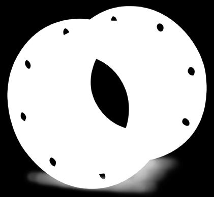
2 Series 230 Rubber Joints Series 230 Rubber Expansion Joints are designed for piping systems to absorb pipe movements, relieve stress, reduce system noise/vibration, compensate for misalignment/offset and to protect rotating mechanical equipment against start-up surge forces. The Style 232 and FA232: Double wide-arch product where more movement is needed. Available in open arch and filled arch configurations. Features and Benefits: Absorbs Directional Movement Thermal movements appear in any rigid pipe system due to temperature changes. The Series 230 wide arch expansion joints allow for axial compression or axial extension, lateral deflection as well as angular and torsional movements. (Note: Rated movements in this publication are based on one plane movements. Multiple movement conditions are based on a multiple movement calculation.) Less Turbulence or Material Entrapment The Series 230 expansion joints are manufactured with the integral rubber flange joining the body at a true 90º angle. This ensures the product will install snug against the mating pipe flange free of voids creating less turbulence in the pipe system. The Series 230 is also available with a filled arch for applications that have 20% or more solids in the process. Absorbs Vibration, Noise and Shock The Series 230 rubber expansion joints effectively dampen and insulate downstream piping against the transmission of noise and vibration generated by mechanical equipment. Noise and vibrations caused by equipment can cause stress in pipe, pipe guides, anchors and other equipment downstream. The Series 230 expansion joints will help relieve noise and vibration occurrences in a pipe system. Water hammer and pumping impulses can also cause strain, stress or shock to a piping system. Install the Series 230 to help compensate for these system pressure spikes. Compensates for Misalignment Rubber expansion joints are commonly used by contractors and plant personnel to allow for slight pipe misalignment during installation of new piping and or replacement applications. (Although rubber expansion joints can be made with permanent offsets, it is suggested that piping misalignments be limited to no more than 1/2 the rated catalog movement.) Wide Service Range and Less Weight Engineered to operate up to 200 PSIG (nominal size dependent) Or up to 250ºF (elastomer dependent), the Series 230 can be specified for a wide range of piping system requirements. The Series 230 rubber expansion joints are constructed in various elastomers with rubber impregnated polyester tire cord and reinforced with wire to create a product with greater operating performance. Material Identification All Series 230 expansion joints are strip branded with cure dates and elastomer designations. All Neoprene Tube/Neoprene Cover (NN) and Nitrile Tube/Neoprene Cover (NP) elastomer designated joints meet the Coast Guard Requirements and conform to ASTM F Protecting Piping and Equipment Systems from Stress/Motion Table 1: Available Materials Temperatures Material Code Cover 1,2 Elastomer Tube 1,2 Elastomer Maximum Operating Temp. ºF (ºC) Branding Label Color F.S.A. Material Class BB Chlorobutyl Chlorobutyl 250º (121º) Black STD. III EE EPDM EPDM 250º (121º) Red STD. III EQ EPDM FDA-EPDM 250º (121º) Red 3 STD. II NH Neoprene CSM 212º (100º) Green STD. II NN Neoprene Neoprene 225º (107º) Blue STD. II NF Neoprene FDA-Neoprene 225º (107º) Blue 3 STD. II NP Neoprene Nitrile 212º (100º) Yellow STD. II NR Neoprene Natural Rubber 180º (82º) White STD. I NG Neoprene Natural Gum 180º (82º) Tan STD. I 1 Information subject to change without notice. Notes: All Products are reinforced with Polyester Tire Cord 1. Expansion Joint Cover can be coated with CSM UV Resistant Coating. 2. All NN & NP elastomer designated joints meet the Coast Guard Requirements and conform to ASTM F and are marked accordingly. 3. Branding Label will be marked as Food Grade. 4. All elastomers above are not intended for steam service 5. BB or EE are good for 300 F blower service at 20 PSI or less.
3 Style 232 Performance Data Table 2: Sizes Movements Design Pressures Weights Expansion Joint Size Nom. I.D. Neutral Length 232 Movement Capability: 1, 2 From Neutral Position (Non-Concurrent) Axial Compression Axial Extension Lateral Deflection Angular Deflection 5 (Degrees) Torsional Rotation 6 (Degrees) Thrust Factor 7 In2 / (cm2) Operating Conditions 3 Positive PSIG (Bar) Vacuum Inches of Hg / (mm of Hg) 8 Expansion Joint Weights Ibs / (kgs) 4 Retaining Ring Set Control Rod Assembly (254) 0.8 (20) 0.9 (24) (48) 200 (1) 3.0 () 2.5 (1.1) 2.3 (1.0) 2 (50) 10 (254) (70) (35) 1.2 (32) (1) (1.8) (1.8) (1.3) 2.5 (65) 10 (254) (70) (35) 1.2 (32) (101) 200 (1) () () (1.3) 3 10 (254) (70) (35) 1.2 (32) (125) 200 (1) 6.0 (2.7) 5.5 (4.3) (1.3) 4 (100) 10 (254) (70) (35) 1.2 (32) (180) 200 (1) 8.5 (3.9) 8.0 (3.6) (1.3) 5 (125) 10 (254) (36) (246) 190 (13.0) 9.5 (4.3) 8.5 (3.9) (1.8) 6 (150) (254) (305) (36) (322) 190 (13.0) 11.5 (5.2) 9.5 (4.3) (1.8) 8 (200) (254) (305) (36) (503) 190 (13.0) 16.0 (7.3) 1 (6.6) 8.0 (3.6) 10 (250) 14 (356) (36) (774) 190 (13.0) 29.0 (1) 17.0 (7.7) 10.0 () 12 (300) 14 (356) (1045) 190 (13.0) 36.0 (16.3) 2 (11.0) 10.0 () 14 (350) (356) (406) (1356) 130 (9.0) 4 (20.0) 27.0 (12.3) 1 (5.4) 16 (400) (356) (406) (1708) 115 (8.0) 53.0 (2) 33.5 (15.2) 15.0 (6.8) 18 (450) (356) (406) (2100) 115 (8.0) 61.0 (27.7) 3 (15.5) 16.0 (7.2) 20 (500) (356) (406) (2533) 115 (8.0) 73.0 (33.1) 38.0 (17.2) 16.0 (7.2) 24 (600) 16 (406) (100) (50) 1.8 (46) (36) 100 (7.0) 88.0 (40.0) 48.0 (21.8) 20.0 (9.1) 30 (750) 16 (406) (102) (50) 1.8 (46) (5434) (57.6) 63.0 (28.6) 29.5 (13.3) 34 (850) 16 (406) (102) (50) 1.8 (46) (6842) (60.8) 7 (32.7) 43.0 (19.5) 36 (900) 16 (406) (102) (50) 1.8 (46) (7607) (70.8) 76.0 (3) 45.0 (20.4) 42 (1050) 16 (406) 4.8 (120) 2.4 (60) 2.2 (56) (10505) 80 (5.5) (95.7) (45.4) 47.0 (21.3) 48 (1200) 16 (406) 4.8 (120) 2.4 (60) 2.2 (56) (13455) 80 (5.5) 22 (101.0) 13 (59.9) 49.0 (22.2) Neutral lengths in RED are the recommended minimum lengths. Metric Conversion Formula: Nominal I.D. : in. x 25 = mm; Neutral length: in. x 25.4 = mm 2

 Axial Compression Axial Extension Lateral Deflection Angular Deflection 5 (Degrees) Torsional Rotation 6 (Degrees)")
4 Style 232 Performance Data continued... Table 2: Sizes Movements Design Pressures Weights Expansion Joint Size Nom. I.D. Neutral Length 232 Movement Capability: 1, 2 From Neutral Position (Non-Concurrent) Axial Compression Axial Extension Lateral Deflection Angular Deflection 5 (Degrees) Torsional Rotation 6 (Degrees) Thrust Factor 7 In2 / (cm2) Operating Conditions 3 Positive PSIG (Bar) Vacuum Inches of Hg / (mm of Hg) 8 Expansion Joint Weights Ibs / (kgs) 4 Retaining Ring Set Control Rod Assembly 9 54 (1350) 16 (406) 60 (1500) 18 (450) 66 (1650) 18 (450) 72 (1800) 18 (450) 78 (1950) 18 (450) 84 (2100) 18 (450) 96 (2400) 18 (450) 108 (2700) 18 (450) 120 (3000) 18 (450) 4.8 (120) 4.8 (120) 4.8 (120) 4.8 (120) (112) (112) (112) (112) (112) 2.4 (60) 2.4 (60) 2.4 (60) 2.4 (60) 2.5 (64) 2.5 (64) 2.5 (64) 2.5 (64) 2.5 (64) 2.2 (56) 2.2 (56) 2.2 (56) 2.2 (56) (51) (51) (51) (51) (51) (16770) (20703) (24771) (29244) (34907) (40136) (51689) (64702) (79173) 80 (5.5) 80 (5.5) 80 (5.5) 70 (5.0) (127.7) (162.7) (190.1) (217.2) 75 (34) (371.5) (589.7) 146 (66) (825.5) (162.7) (90.7) (108.8) (131.5) (142.9) (158.0) (170.5) (192.7) (256.2) 67.0 (30.4) 7 (32.7) 75.0 (3) 9 (42.6) (50.3) (54.9) 13 (60.8) (69.4) (75.7) NOTES: 1. Concurrent Movements - Concurrent movements are developed when two or more movements in a pipe system occur at the same time. If multiple movements exceed single arch design there may be a need for additional arches. To perform calculation for concurrent movement when a pipe system design has more than one movement, please use the following formula: Actual Axial Compression + Actual Axial Extension + Actual Lateral (X) + Actual Lateral (Y) = / <1 Rated Axial Compression + Rated Axial Extension + Rated Lateral (X) + Rated Lateral (Y) Calculation must be equal to or less than 1 for expansion joint to operate within concurrent movement capability. 2. Filled Arch Rubber Expansion Joints - Known as Style FA 232. The Series FA230 rubber expansion joints should be selected when there are 20% or more solids being conveyed in the pipe system. The filled arch products are manufactured with seamless tube filled with a lower durometer rubber in the arch core. The filled arch product will have a 50% reduced movement capability from the information provided in Table Pressure rating is based on 170 F operating temperature with a 4:1 safety factor. At higher temperatures, the pressure rating is reduced slightly. Hydrostatic testing at 1.5 times rated maximum catalogue pressure or design working pressure of pipe system for 10 minutes is available upon request. 4. Weights are approximate and vary due to length. Effective Area 5. The degree of angular movement is based on the maximum rated extension. Thrust Factor= 6. Torsional movement is expressed when the expansion joint is at neutral length. 7. Calculation of Thrust (Thrust Factor). When expansion joints are installed in the pipeline, the static portion of the thrust is calculated as a product of the area of the I.D. of the arch of the expansion joint times the maximum pressure (design, test or surge) that will occur in the line. The result is a force expressed in pounds. Take Design, surge or test pressure X thrust factor to calculate end thrust. 8. Parts listed at Hg / 660 mm Hg vacuum have a design rating of 30 Hg / 762 mm Hg (full vacuum). Vacuum rating is based on neutral installed length, without external load. Products should not be installed extended on vacuum applications. 9. Limit rod unit weight consists of one rod with washers, nuts and two limit rod plates. Multiply number of limit rods needed for the application (as specified in the Fluid Sealing Association s Technical Handbook, Seventh Edition or table 4 in this manual) to determine correct weights. 3

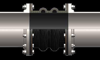

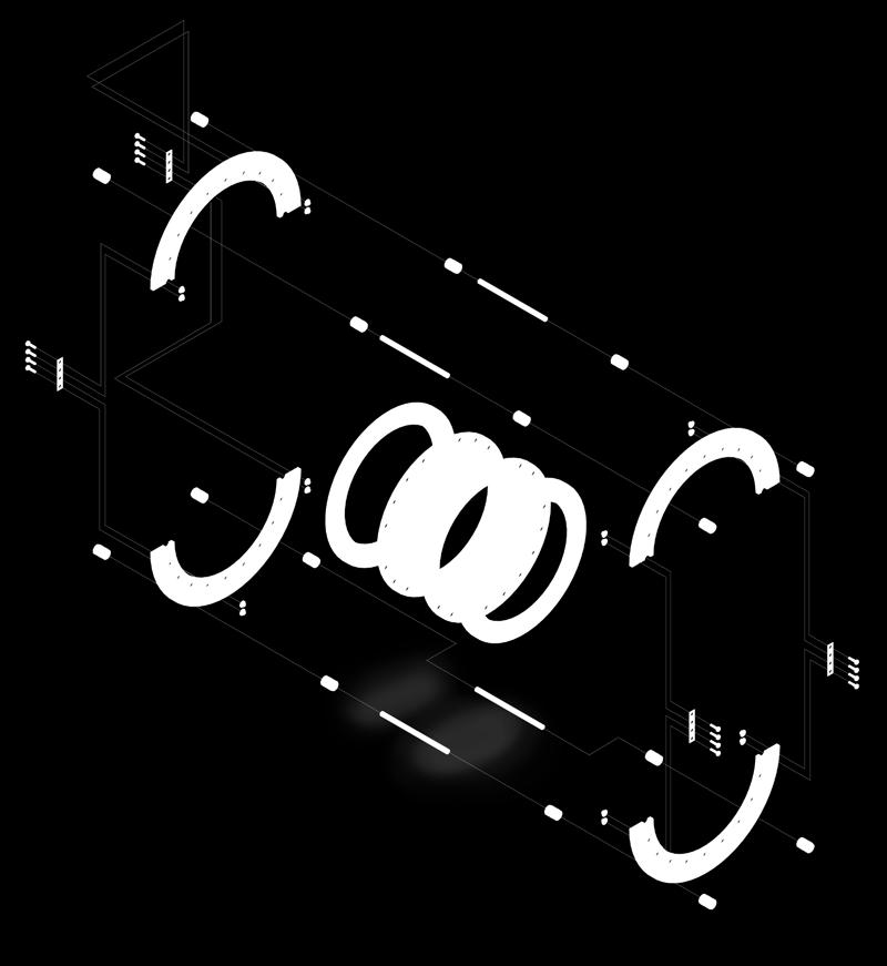
5 Style 232 & 232 FA Style 232 Style 232 FA 4
6 Style 230 Drilling Chart Table 5 Standard Drilling for Rubber Expansion Joints Thickness of Materials for Rubber Expansion Joints Nominal Pipe Size Expansion Joint I.D. Inch /(mm) Flange O.D. Flange Dimensions 2 Bolt Circle Number Of Holes Size Of Holes Material Thickness 1 for Bolt Length Requirements Retaining Rings Thickness Rubber Flange Thickness Adjacent 3 Mating Flange Thickness Max. Control 4 Rod Plate Thickness Control Unit Plate Detail Control Rod 6 Plate O.D. Maximum 7 Rod Diameter 1 (25) 4.25 (107.95) 3.13 (79.50) (15.9) (9.53) (11.99) (15.9) (212.7) (15.9) 1.25 (32) 4.63 (117.60) 3.50 (88.90) (15.9) (9.53) (11.99) (15.9) (222.3) (15.9) (127.00) 3.88 (98.55) (15.9) (9.53) (11.99) (9.5) (231.8) (15.9) 2 (50) 6.00 (152.40) 4.75 (120.65) (19.1) (9.53) (11.99) (12.7) (257.2) (15.9) 2.5 (65) 7.00 (177.80) 5.50 (139.70) (19.1) (9.53) (11.99) (12.7) (282.6) (25.4) (190.50) 6.00 (152.40) (19.1) (9.53) (11.99) (12.7) 125 (295.3) (25.4) 3.5 (90) 8.50 (215.90) 7.00 (177.80) (19.1) (9.53) (11.99) C (15.9) (320.7) (25.4) 4 (100) 9.00 (228.60) 7.50 (190.50) (19.1) (9.53) (11.99) U (15.9) (333.4) (25.4) S 5 (125) (250) 8.50 (215.90) (22.2) (9.53) (10) (15.9) (358.8) (25.4) T 6 (150) (279.40) 9.50 (241.30) (22.2) (9.53) (10) O (12.7) (384.2) (25.4) 8 (200) (342.90) (298.45) (22.2) (9.53) (16.00) M (19.1) (485.8) (25.4) E 10 (250) (406.40) (361.95) (25.4) (9.53) (16.00) R (19.1) 225 (549.3) (25.4) 12 (300) (482.60) (431.80) (25.4) (9.53) (19.00) (19.1) (625.5) (25.4) 14 (350) (533.40) (476.25) (28.6) (9.53) (20) T (19.1).625 (676.3) (25.4) O 16 (400) (596.90) (539.75) (28.6) (9.53) (20) (19.1) (765.2) (31.8) 18 (450) (635.00) (577.85) (31.8) (9.53) (20) S (19.1) 325 (803.3) (31.8) P 20 (500) (698.50) (635.00) (31.8) (9.53) (24.99) (19.1) (866.8) (31.8) E 22 (550) (749.30) (692.15) (34.9) (9.53) (24.99) C (25.4) (917.6) (31.8) 24 (600) 30 (810) (749.30) (34.9) (9.53) (24.99) I (25.4) (981.1) (31.8) F (650) (869.95) (806.32) (34.9) (9.53) (24.99) Y (25.4) (1038.2) (31.8) 28 (700) (927.10) 30 (863.60) (34.9) (9.53) (24.99) (31.8) (1120.8) (38.1) 30 (750) (984.25) (914.40) (34.9) (9.53) (24.99) M (31.8) (1177.9) (38.1) A 32 (800) ( ) (977.90) (41.3) (9.53) (24.99) T (31.8) (1254.1) (38.1) 34 (850) ( ) ( ) (41.3) (9.53) (24.99) I (38.1) (1330.3) (4) N 36 (900) ( ) ( ) (41.3) (9.53) (24.99) (38.1) (1387.5) (4) G 38 (950) ( ) ( ) (41.3) (9.53) (24.99) (38.1) (1457.3) (4) 40 (1000) ( ) ( ) (41.3) (9.53) (24.99) F (38.1) (1482.7) (4) L 42 (1050) ( ) ( ) (41.3) (9.53) (30.00) A (38.1) 625 (1565.3) (4) 44 (1100) ( ) ( ) (41.3) (9.53) (30.00) N (38.1) (1622.4) (4) G 46 (1150) ( ) ( ) (41.3) (9.53) (30.00) (38.1) (167) (4) E 48 (1200) ( ) ( ) (41.3) (9.53) (30.00) (38.1) (1730.4) (4) 50 (1250) ( ) ( ) (47.6) (9.53) (30.00) T (38.1) (1787.5) (4) H 52 (1300) 60 ( ) ( ) (47.6) (9.53) (30.00) I (4) (1870.7) 00 (50.8) 54 (1350) ( ) ( ) (50.8) (9.53) (30.00) C 00 (50.8) (1927.2) 00 (50.8) 56 (1400) ( ) ( ) (47.6) (9.53) (30.00) K 00 (50.8) (1990.7) 00 (50.8) N 58 (1450) ( ) ( ) (47.6) (9.53) (30.00) E 00 (50.8) (2047.9) 00 (50.8) 60 (1500) ( ) ( ) (50.8) (9.53) (30.00) S 00 (50.8) (2098.7) 00 (50.8) 66 (1650) (2030) ( ) (50.8) (9.53) (30.00) S 00 (50.8) (2276.5) 00 (50.8) 68 (1700) ( ) ( ) (50.8) (9.53) (30.00) 00 (50.8) (2333.6) 00 (50.8) 72 (1800) ( ) ( ) (50.8) (9.53) (30.00) 00 (50.8) (244) 00 (50.8) 78 (1950) ( ) (20.60) (53.0) (9.53) (30.00) 00 (50.8) (19.4) (57.2) 84 (2100) ( ) ( ) (57.2) (9.53) (30.00) 00 (50.8) (2790.8) (57.2) 90 (2250) ( ) 100 ( ) (60.3) (9.53) (30.00) 00 (50.8) (2975.0) (63.5) 96 (2400) 115 ( ) ( ) (63.5) (9.53) (30.00) 00 (50.8) (3165.9) (69.9) 5

 Customer to Specify Mating Flange Thickness 00 (50.8) 131.375 (3336.5) 2.750 (69.9) 108 (2700) 1.75 (3219.45) 120.75 (3067.05) 72 2.625 (66.7) 0.375 (9.53) 1.181 (30.00) 00 (50.8) 138.125 (3508.")


7 Style 230 Drilling Chart continued... Table 5 Standard Drilling for Rubber Expansion Joints Thickness of Materials for Rubber Expansion Joints Nominal Pipe Size Expansion Joint I.D. Inch /(mm) Flange O.D. Flange Dimensions 2 Bolt Circle Number Of Holes Size Of Holes Material Thickness 1 for Bolt Length Requirements Retaining Rings Thickness Rubber Flange Thickness Adjacent 3 Mating Flange Thickness Max. Control 4 Rod Plate Thickness Control Unit Plate Detail Control Rod 6 Plate O.D. Maximum 7 Rod Diameter 102 (2550) ( ) 110 ( ) (66.7) (9.53) (30.00) Customer to Specify Mating Flange Thickness 00 (50.8) (3336.5) (69.9) 108 (2700) 1.75 ( ) ( ) (66.7) (9.53) (30.00) 00 (50.8) (3508.4) (69.9) 120 (3000) ( ) ( ) (73.0) (9.53) (30.00) 00 (50.8) (386) (76.2) Metric Conversion Formula: Nominal I.D. : in. x 25 = mm; Neutral length: in. x 25.4 = mm Notes: 1. Limit/Control Rod length is determined by neutral length of rubber expansion joint, rated extension, control rod plate thickness, mating flange thickness and number of nuts. 2. Flange Dimensions shown are in accordance with ANSI B16.1 and ANSI B16.5 Class 125/150, AWWA C , Tbl 2 and 3 - Class D, Table 4 - Class E. Hole size shown is 1/8 larger than AWWA Standard. 3. Adjacent mating flange thickness is required to determine overall rod length and compression sleeve length (if required). 4. Plate thickness is based on a maximum width we would use to design a Limit/Control Rod plate. 5. Flat Washers required at ring splits and are by others. 6. Control rod plate O.D. installed dimension is based on a maximum O.D. we would supply. 7. Control rod diameter is based on a maximum diameter we would use to design a control rod. A - Retaining Ring Thickness. B - Rubber Flange Thickness. C - Adjacent Mating Flange Thickness (By Others). D - Control Unit Plate Thickness. E - Double Nut Thickness is determined by Control Rod Diameter. F - Control Rod Bolt Length is determined by A through E + OAL 1. G - Control Rod Control Rod Plate O.D. H - Maximum Rod Diameter Figure 1 Figure 2 Figure 3 6
 placed across an expansion joint from flange to flange to minimize possible damage caused by excessive motion of a pipeline.")
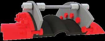
8 Limit Rods, Control Rods & Compression Sleeves Use of Control Units with Rubber Expansion Joints Definition A control unit assembly is a system of two or more control rod units (limit rods, tie rods or compression sleeves) placed across an expansion joint from flange to flange to minimize possible damage caused by excessive motion of a pipeline. The control unit assemblies can be set at the maximum allowable expansion and/or contraction of the rubber expansion joint. When used in this manner, control units are an additional safety factor and can minimize possible damage to adjacent equipment. Rubber expansion joints should be installed between two fixed anchor points in a piping system. The pipe system must be rigidly anchored on both sides of the expansion joint to control expansion or contraction of the line. Piping anchors must be capable of withstanding the line thrusts generated by internal pressure or wide temperature fluctuations. When proper anchoring cannot be provided, CONTROL UNITS ARE REQUIRED. For un-anchored piping systems nuts shall be tightened snug against rod plate to prevent over extension due to pressure thrust created by expansion joint. Refer to Thrust Factor in Table 2, note 5 in this manual. Listed below are three (3) control unit configurations supplied and are commonly used with rubber expansion joints in piping systems. Figure 1 Known as a LIMIT ROD, this control unit configuration will allow an expansion joint to extend to a predetermined extension setting. Nuts shall be field set to no more than the maximum allowable extension movement of a rubber expansion joint (unless used in an un-anchored system). Refer to Table 2 in this manual for allowable movement capabilities. Spherical washers can also be furnished (upon request) to combat any nut to plate binding during offset. Consult the systems engineer for proper nut settings prior to system operation. Figure 2 Known as a LIMIT/CONTROL ROD, this control unit configuration is used to allow specified pipe expansion (expansion joint axial compression) and pipe contraction (expansion joint axial extension) movements. Nuts shall be field set to no more than the maximum allowable extension (unless used in an un-anchored pipe system) or compression of a rubber expansion joint. Refer to Table 2 in this manual for allowable movement capabilities. Internal and external nuts can also be field set to allow for no movement in the horizontal plane. This setting will allow the rubber to move laterally while keeping expansion joint thrust forces low on adjacent equipment. Spherical washers can also be furnished (upon request) to combat any potential nut to plate binding during offset. Limit/Control rods with internal nuts must be specified at the time of inquiry. Consult the systems engineer for proper nut settings prior to system operation. Figure 3 Known as a COMPRESSION SLEEVE, this configuration is used to allow for specified pipe expansion (expansion joint axial compression) and pipe contraction (expansion joint extension) movements. Nuts shall be field set to no more than the maximum allowable extension (unless used in an un-anchored pipe system) of a rubber expansion joint. Refer to Table 2 in this manual for allowable movement capabilities. We will supply each compression sleeve to allow for no axial movement unless otherwise specified by the purchaser. Compression sleeves shall be field trimmed to meet required allowable axial movement as set forth by system requirements. Spherical washers can also be furnished (upon request) to combat any potential nut to plate binding during offset. Consult the systems engineer for proper sleeve lengths prior to system operation. Important Control Unit Considerations The number of rods, control rod diameters and control rod plate thicknesses are important considerations when specifying control units for an application. As a minimum, specifying engineers or purchasers shall follow the guidelines as set forth in Appendix C of the Fluid Sealing Association s Technical Handbook, Seventh Edition. We engineer o ur control unit assemblies to system requirements. Our designs incorporate an allowable stress of 65% of material yield for each rod and plate (rod and plate material to be specified by purchaser). Therefore, it is important to provide pressure and temperature ratings when requesting control units for rubber expansion joints. It is also important to provide adjacent mating flange thickness or mating specifications to ensure correct rod lengths are provided. Installation Instructions for Control Rods 1. Assemble expansion joint between pipe flanges in its manufactured face-to-face length. Install the retaining rings furnished with the expansion joint. 2. Assemble control rod plates behind pipe flanges as shown. Flange bolts or all thread studs through the control rod plate must be longer to accommodate the plate thickness. Control rod plates should be equally spaced around the flange. Depending upon the size and pressure rating of the system, 2, 3, 4, or more control/ limit rods may be required. Refer to Table 4 in this manual or to the Fluid Sealing Association s Technical Handbook, Seventh Edition, page 23 for control rod pressure ratings. 3. Insert control/limit rods through top plate holes. Steel flat washers are to be positioned at outer plate surface. 4. If a single nut per unit is furnished, position this nut so that there is a gap between the nut and the steel flat washer. This gap is equal to the joints maximum extension (commencing with the nominal face-to-face length). To lock this nut in position, either stake the thread in two places or tack weld the nut to the rod. If two nuts are supplied, the nuts will create a jamming effect to prevent loosening. (Nuts should be snug against flat washer and control rod plate when piping system is un-anchored.) Note: Consult the manufacturer if there are any questions as to the rated compression and elongation. These two dimensions are critical in setting the nuts and sizing the compression pipe sleeve (if supplied). 5. If there is a requirement for compression pipe sleeves, ordinary pipe may be used, sized in length to allow the joint to be compressed to its normal limit. 6. If there is a requirement for optional spherical washers, these washers are to be positioned at outer plate surface and backed up by movable double nuts. 7


 186 371 8 (203) 163 3 10 (254) 163 325 488 12 (305) 160 320 481 14 (356) 112 223 335 16 (406) 113 227 340 453 18")
 70 141 211 281 32 (813) 63 125 188 251 34 (864) 72 143 215 286 36 (914) 69 138 207 276 38 (965) 63 125 188")
 37 75 112 150 52 (1321) 35 70 105 140 54 (1372) 43 86 128 171 56 (1422) 40 80 120 160 58 (1473) 38 75 113 150 60")
 53 79 106 98 (2489) 29 58 86 115 102 (2591) 25 51 76 102 108 (2743) 23 46 75 92 120 (3048) 18 37 56 75")
9 Limit Rods, Control Rods & Compression Sleeves continued... Optional Spherical Washers Optional Spherical Washers Optional Spherical Washers Figure 1 LIMIT ROD Configuration Figure 2 LIMIT/ CONTROL ROD Configuration Figure 3 COMPRESSION SLEEVE Configuration Table 6 Nominal Pipe Size Expansion Joint I.D. Inch /(mm) Maximum Surge or Test Pressure of the Systems Number of Control Rods Recommended (51) (102) (152) (203) (254) (305) (356) (406) (457) (508) (559) (610) (711) (762) (813) (864) (914) (965) (1016) (1067) (1118) (1168) (1219) (1270) (1321) (1372) (1422) (1473) (1524) (1575) (1676) (1829) (1981) (2134) (2286) (2489) (2591) (2743) (3048) Notes: 1. Pressures listed above do not relate to the actual design pressure of the expansion joint products, but are the maximum surge or pressure for a specific control rod nominal pipe size. 8
10 Installation Instructions for Non-Metallic Expansion Joints 1. Service Conditions: Make sure the expansion joint rating for temperature, pressure, vacuum and movements match the system requirements. Contact the manufacturer for advice if the system requirements exceed those of the expansion joint selected. Check to make sure the elastomer selected is chemically compatible with the process fluid or gas. 2. Alignment: Expansion joints are normally not designed to make up for piping misalignment errors. Piping should be lined up within 1/8. Misalignment reduces the rated movements of the expansion joint and can induce severe stress and reduce service life. Pipe guides should be installed to keep the pipe aligned and to prevent undue displacement. 3. Anchoring: Solid anchoring is required wherever the pipeline changes direction and expansion joints should be located as close as possible to anchor points. If piping is not adequately anchored, control rods should be used. If anchors are not used, pressure thrust may cause excessive movement damaging the expansion joint. 4. Pipe Support: Piping must be supported by hangers or anchors so expansion joints do not carry any pipe weight. 5. Mating Flanges: Install the expansion joint against the mating pipe flanges and install bolts so that the bolt head and washer are against the retaining rings. If washers are not used, flange leakage can result particularly at the split in the retaining rings. Flange-to-flange dimension of the expansion joint must match the breech opening. Make sure the mating flanges are clean and are flat faced type or no more than 1/16 raised face type. Never install expansion joints that utilize split retaining rings next to wafer type check or butterfly valves. Serious damage can result to a rubber joint of this type unless installed against full face flanges. 6. Bolting Torque: Table 5 shows the recommended torque ranges for non-metallic expansion joints with full-faced rubber flanges: Torque specifications are approximate. Tighten bolts in stages using cross-bolt tightening pattern. If the joint has integral fabric and rubber flanges, the bolts should be tight enough to make the rubber flange OD bulge between the retaining rings and the mating flange. After installation, the system should be pressurized and examined to confirm a proper seal. Torque bolts sufficiently to assure leak free operation at hydrostatic test pressure. Note: Torque values are approximate due to mating flange surfaces, installation offsets, operating pressures and environmental conditions. 7. Storage: Ideal storage is in a warehouse with a relatively dry, cool location. Store flanges face down on a pallet or wooden platform. Do not store other heavy items on top of expansion joints. Ten year shelf life can be expected with ideal conditions. If storage must be outdoors, place on wooden platform and joints should not be in contact with the ground. Cover with a tarpaulin. Table 7 Approximate Size Torque Values 1 THRU ft/lbs 2.5 THRU ft/lbs 6 THRU ft/lbs 14 THRU ft/lbs 20 THRU ft/lbs THRU ft/lbs 42 THRU ft/lbs 52 THRU ft/lbs 66 THRU ft/lbs 78 THRU ft/lbs 96 THRU ft/lbs ft/lbs 8. Large Joint Handling: Do not lift with ropes or bars through the bolt holes. If lifting through the bore, use padding or a saddle to distribute the weight. Make sure cables or forklift tines do not contact the rubber. Do not let expansion joints sit vertically on the edges of the flanges for any period of time. 9. Additional Tips: A. Do not insulate over a non-metallic expansion joint; however, if insulation is required, it should be made removable to permit easy access to the flanges. This facilitates periodic inspection of the tightness of the joint bolting. B. It is acceptable (but not necessary) to lubricate the expansion joint flanges with a thin film of graphite dispersed in glycerin or water to ease disassembly at a later time. C. Do not weld in the near vicinity of a non-metallic joint. D. If expansion joints are to be installed underground, or will be submerged in water, contact manufacturer for specific recommendations. E. If the expansion joint will be installed outdoors, make sure the cover material will withstand ozone, sunlight, etc. F. Check the tightness of lead-free flanges two or three weeks after installation and retighten if necessary. Warning: Expansion joints may operate in pipelines or equipment carrying fluids and/or gasses at elevated temperature and pressures and may transport hazardous materials. Precautions should be taken to protect personnel in the event of leakage or splash. Rubber joints should not be installed in areas where inspection is impossible. Make sure proper drainage is available in the event of leakage when operating personnel are not available. 9


11 Piping System Layout Examples Anchored System Figure 1 Figure 2 Anchored System Note: Although limit rods, control rods or limit rods with compression sleeves are not required in an anchored pipe system, you may want to consider using them. If an anchor were to fail, any rod configuration would be capable of handling the pressure thrust of the system and lessen the likelihood of an expansion joint failure. Un-Anchored System Pump Figure 1 Figure 3 Un-Anchored System Note: Rod sets should be installed so that external nuts are snug against the plate at installation. Pressure thrust of the pipe system can cause expansion joint to over-elongate and reduce movement capabilities. Figure 2 Pump Figure 3 10


12
Style 233-L & 234-L Rubber Joints
 Style 33-L & 3-L Rubber Joints Style 33-L Rubber s are designed for piping systems that experience large lateral offsets due to settlement. The Style 33-L is a low profile triple arch design with a built-in
Proco Series 230 Rubber Joints
 Proco Series 230 Rubber Joints Proco Series 230 Rubber Expansion Joints are designed for piping systems to absorb pipe movements, relieve stress, reduce system noise/vibration, compensate for misalignment/offset
Proco s Headquarters. Largest Inventory of Expansion Joints and Check Valves
 Proco s Headquarters Largest Inventory of xpansion Joints and Check Valves 1 Proco Style RC & R Rubber Joints Proco Style RC & R Rubber xpansion Joints are designed for piping systems to absorb pipe movements,
Proco Style 240/242 Molded Spherical Joints
 Proco Style /22 Molded Spherical Joints Proco Style /22 Spherical Molded Expansion Joints are designed for piping systems to absorb pipe movements, relieve stress, reduce system noise/vibration, compensate
Proco Style 240 Molded Spherical Joints
 Proco Style Molded Spherical Joints Proco Style Spherical Molded Expansion Joints are designed for piping systems to absorb pipe movements, relieve stress, reduce system noise/ vibration, compensate for
Proco Style 242 Molded Spherical Joints
 Proco Style 22 Molded Spherical Joints Proco Style 22 Spherical Molded Expansion Joints are designed for piping systems to absorb pipe movements, relieve stress, reduce system noise/ vibration, compensate
Proco Style 240/242 Molded Spherical Joints
 Proco Style /22 Molded Spherical Joints Proco Style /22 Spherical Molded Expansion Joints are designed for piping systems to absorb pipe movements, relieve stress, reduce system noise/vibration, compensate
Proco Series 260R Molded Wide Arch Expansion Joints
 Proco eries 260R Molded Wide Arch Expansion Joints Proco eries 260R Molded Wide Arch Expansion Joints are specifically designed for use with Plastic or FRP Piping ystems. An option for the standard spool-type
Installation, operation & maintenance manual Integral Tie Rod Design
 Installation, operation & maintenance manual Integral Tie Rod Design Date: 2431 North Wigwam Dr. Stockton, CA 95205 Phone: 800-344-3246 Fax: 209-943-0242 Email: sales@procoproducts.com Table of Contents
Installation, Operation & Maintenance Manual RC/RE Series
 Document Title Installation, Operation & Maintenance Manual RC/RE Series Date: 2431 North Wigwam Dr. Stockton, CA 95205 Phone: 800-344-3246 Fax: 209-943-0242 Email: sales@procoproducts.com Table of Contents
Installation, operation & maintenance manual
 Installation, operation & maintenance manual 2431 North Wigwam Dr. Stockton, CA 95205 Phone: 800-344-3246 Fax: 209-943-0242 Email: sales@procoproducts.com Table of Contents 1.0 Introduction 2 2.0 Storage
Installation, Operation & Maintenance Manual
 Installation, Operation & Maintenance Manual Style 240/242 Date: 2431 North Wigwam Dr. Stockton, CA 95205 Phone: 800-344-3246 Fax: 209-943-0242 Email: sales@procoproducts.com Table of Contents 1.0 Introduction:
SERIES ASM NEOPRENE/EPMD FLANGED SINGLE SPHERE CONNECTOR CONNECTORS. Pressures to 225 PSIG (15.51 barg) Temperatures to 230ºF (110ºC)
 Temperatures to 230ºF (110ºC)") CONNECTORS APPLICATIONS Process Industry Weak Acids Alkalies Compressed Air Pulp & Paper MODELS ASM - Flanged Connection OPTIONS Control Rods Oil & Gas Water & Waste Pump suction & discharge Sea water
CONNECTORS APPLICATIONS Process Industry Weak Acids Alkalies Compressed Air Pulp & Paper MODELS ASM - Flanged Connection OPTIONS Control Rods Oil & Gas Water & Waste Pump suction & discharge Sea water
Proco Series 300 Flagged Rubber Pipe Connectors
 Proco Series 0 Flagged Rubber Pipe Connectors PROCO Series 0 Rubber Pipe is designed for tough demanding industrial and commercial applications as found in: Chemical-Petrochemical and Industrial Process
EXPANSION JOINT SELECTION GUIDE
 EXPANSION JOINT SELECTION GUIDE The proper selection and application of an expansion joint is the determining factor in its operation and life. Improper selection and application will lead to problems
SERIES ASM NEOPRENE/EPMD FLANGED SINGLE SPHERE CONNECTOR CONNECTORS. Pressures to 225 PSIG (15.51 barg) Temperatures to 230ºF (110ºC)
 Temperatures to 230ºF (110ºC)") CONNECTORS APPLICATIONS Process Industry Weak Acids Alkalies Compressed Air Pulp & Paper MODELS ASM - Flanged Connection OPTIONS Control Rods Oil & Gas Water & Waste Pump suction & discharge Sea water
CONNECTORS APPLICATIONS Process Industry Weak Acids Alkalies Compressed Air Pulp & Paper MODELS ASM - Flanged Connection OPTIONS Control Rods Oil & Gas Water & Waste Pump suction & discharge Sea water
Rubber Expansion Joints
 Rubber Expansion Joints ENGINEERED EXPANSION JOINTS Rubber Expansion Joints MACOGA has more than 40 years of experience in expansion joints and offers the most complete range ever concerning sizes, material,
Style 234 Restrained Flexible Single-Gasket Coupling. System No. Submitted By Spec Sect Para Location Date Approved Date
 Victaulic Bolted Split-Sleeve Products (VBSP) Style 234 carbon steel couplings (formerly Depend-O-Lok Air/FluidMaster) are single-arch couplings that are commonly used in buried or exposed steel pipe applications
TO BE FUNISHED WITH CONTROL UNITS YES NO MOVEMENT CAPABILITY AND FORCES. Elong. (in) Approx Force (Lbs)
 Approx Force (Lbs)") This flexible joint should be installed the length shown on drawing. Piping and equipment connected by this flexible joint must be anchored and guided. If not, control units must be used to prevent movement
This flexible joint should be installed the length shown on drawing. Piping and equipment connected by this flexible joint must be anchored and guided. If not, control units must be used to prevent movement
Series 3500 Externally Pressurized Expansion Joints Catalog 574 H
 Series 3500 Externally Pressurized Expansion Joints Catalog 57 H 500 Laminated Bellows Expansion J Series 3500 on Joints Externally Pressurized Expansion Joints Standard Designs Sizes " through ", 50 &
CPF INSTALLATION, OPERATION, AND MAINTENANCE MANUAL FLANGED SERIES CHECK VALVE *
 CPF INSTALLATION, OPERATION, AND MAINTENANCE MANUAL FLANGED SERIES CHECK VALVE * Elasto-Valve s CPF Series is a flanged, bolt-on duckbill Check Valve manufactured with top quality elastomeric materials.
Mechanical MATERIAL SPECIFICATIONS. Stainless Steel Housing Specifications. Gasket Specifications. Bolt / Nut Specifications
 82 COUPLINGS SYSTEM The Grinnell Stainless Steel System is designed for joining 2" to 12" (54,0mm to 206,4mm) stainless steel piping, schedules 5, 10, and 40. The Figure 472 coupling patented Universal
Ford Fabricated Steel Products
 Ford Fabricated Steel Products Section N2 12/2000 The Ford Meter Box Co., Inc. 775 Manchester Avenue, P.O. Box 443, Wabash, Indiana, USA 46992-0443 Telephone: 219/563-3171 FAX: 1-800-826-3487 Overseas
- METALLIC EXPANSION JOINTS
 EXPANSION JOINTS FOR PIPING SYSTEM - METALLIC EXPANSION JOINTS - NON METALLIC EXPANSION JOINTS EXPANSION JOINTS FOR PIPING SYSTEM - METALLIC EXPANSION JOINTS - NON METALLIC EXPANSION JOINTS - EXPANSION
Keystone Series GR resilient seated butterfly valves GRW/GRL Installation and operation manual
 Before installation these instructions must be fully read and understood Important Before valves are installed or used the following actions are recommended. 1. Valves/parts have to be inspected and thoroughly
ONYX VALVE CO MODEL GSF AND GSD Installation & Maintenance
 ONYX VALVE CO MODEL GSF AND GSD Installation & Maintenance Operation: (04-2011) The Onyx Series GSF and GSD valves operate very simply. Injecting compressed air into the iron housing collapses the rubber
Innerlynx Type UL Fire Rated 3Hour Fire Stop ADVANCE PRODUCTS & SYSTEMS, INC. ISO-9001 CERTIFIED COMPANY - FM
 Innerlynx Type UL Fire Rated 3Hour Fire Stop ADVANCE PRODUCTS & SYSTEMS, INC. ISO-9001 CERTIFIED COMPANY - FM53705 www.apsonline.com Why choose Innerlynx? offer 21 different sizes for all pipe diameters
CompoSeal butterfly valves, wafer style Installation & Maintenance Instructions
 Please read these instructions carefully This symbol indicates important messages and safety instructions. Intended valve use The valve is intended to be used only in applications within the pressure/temperature
Platinum Series FEATURES: Up to 16 Stainless Steel Plies
 Maximum Vibration Absorption Longest Cycle Life Soft Spring Rate = Ease of Installation Maximum Safety Platinum Series Series 151-1215 Welded Fixed Flange Series 150-TR-2115 Van Stone Floating Flange Keflex
Expansion & contraction
 Expansion & contraction All materials expand & contract with thermal change & pressure change. In case of piping systems, this dimension change can produce excessive stresses throughout the piping system
FAX: SPECIAL APPLICATION HOSES, METAL & TEFLON HOSES
 Large Bore Teflon Fittings Selection Pipe Thread (NPT) Style 03 Flanges Lap Joint Flange Style 12 Shown with epoxy coated steel flange Cam and Groove Female Swivel Type Style 16 Also available Teflon Encapsulated
THS SERIES FILTER BUTTERFLY VALVE STYLE FACE PIPING
 THS SERIES FILTER BUTTERFLY VALVE STYLE FACE PIPING INSTALLATION AND USER S GUIDE IMPORTANT SAFETY INSTRUCTIONS READ AND FOLLOW ALL INSTRUCTIONS SAVE THESE INSTRUCTIONS TABLE OF CONTENTS 1.0 PRINCIPALS
VSI, LLC SERIES 2100 RESILIENT SEATED BUTTERFLY VALVES INSTALLATION, OPERATION AND MAINTENANCE MANUAL
 VSI SERIES 2100 RESILIENT SEATED BUTTERFLY VALVES VSI, LLC. 2-0 SERIES 2100 RESILIENT SEATED BUTTERFLY VALVES INSTALLATION, OPERATION AND MAINTENANCE MANUAL Publication: V2100- August 2016 TABLE OF CONTENTS
DESIGN CONSIDERATIONS
 PRESSURE THRUST DESIGN CONSIDERATIONS APPLICATIONS Intermediate Anchor An intermediate anchor is one which divides a pipeline into individual expanding pipe sections containing multiple expansion devices
Steel Fabricated Coupling
 Steel Fabricated Coupling Straight Connection IMPORTANT LINKS Click appropriate words to go to: Standard Limited Warranty Sales Terms & Conditions Freight Policy Returns Policy Corrosion & Product Selection
SERIES. Table 1: Available Materials Temperatures
 PROCO 700 SERIES 1 The PROCO Series 700 ProFlex Rubber Check Valves are a cost effective way to control back pressures from sewage treatment plants, outfalls and tidal operations. They are a fully passive
Type B (Extruded Branch) Sizes 4 through 30
 Sizes 4 through 30") STOPPLE Fittings & Reduced Branch Split Tees, Sizes 4-inch and Larger Bulletin No: 1100.001.05 Date: July 2008 Cross Indexing No: n/a Supersedes: 1100.001.04 (07/06) Typical Tapping Setup For Plugging
STOPPLE Fittings & Reduced Branch Split Tees, Sizes 4-inch and Larger Bulletin No: 1100.001.05 Date: July 2008 Cross Indexing No: n/a Supersedes: 1100.001.04 (07/06) Typical Tapping Setup For Plugging
FIG Gruvlok Flanges
 Gruvlok Flanges The Gruvlok Fig. 7012 Flange allows direct connection of Class 125 or Class 150 flanged components to a grooved piping system. The two interlocking halves of the 2" thru 12" sizes of the
BUTTERFLY VALVES. An industry leader in underground and in-plant applications. STYLE STYLE Consult factory for sizes
 An industry leader in underground and in-plant applications. BUTTERFLY VALVES STYLE 4500 3 24 STYLE 1450 30 54 Consult factory for sizes 60 120 C504 Class 150B & 250B M&H Valve is a division of McWane,
A joint reliance. SJT series METAL EXPANSION JOINT SJT-0107
 A joint reliance SJT series METAL EXPANSION JOINT S J T SJT-0107 SJT series METAL EXPANSION JOINT FEATURES Bellow Expansion Joints are employed in piping systems to absorb differential thermal expansion
Hole-cutting. cutting a hole. After the hole has been cut all rough edges must be removed and the area within 5/8 (16mm) of the hole
 of the hole") Mechanical Tees Hole-cutting Shurjoint mechanical tees provide a fast and easy mid-point branch outlet, eliminating the need for welding or the use of multiple fittings. The Model M21 features a female
Mechanical Tees Hole-cutting Shurjoint mechanical tees provide a fast and easy mid-point branch outlet, eliminating the need for welding or the use of multiple fittings. The Model M21 features a female
SCOPE OF WORK WASTEWATER TREATMENT PLANT THE WORLD LEADER IN PIPE JOINING SOLUTIONS
 SCOPE OF WORK WASTEWATER TREATMENT PLANT THE WORLD LEADER IN PIPE JOINING SOLUTIONS THE VICTAULIC DIFFERENCE HOUSING GROOVE GASKET BOLT/NUT GROOVE GROOVED PIPE JOINING TECHNOLOGY How does it work? The
SERIES. Table 1: Available Materials Temperatures
 PROCO 700 SERIES 1 The PROCO Series 700 ProFlex Rubber Check Valves are a cost effective way to control back pressures from sewage treatment plants, outfalls and tidal operations. They are a fully passive
411 Steel Couplings Material Specifications
 411 Steel Couplings Material Specifications Gasket Material Specifications STANDARD: Nitrile (Buna-N)-NSF 61 Compounded to produce superior storage and performance characteristics while resisting water,
ONYX VALVE CO MODEL DAC-PFO Installation & Maintenance
 ONYX VALVE CO MODEL DAC-PFO Installation & Maintenance OPERATION: (01-10) The Onyx series DAC-PFO pinch valve fails open on loss of air. This simple spring and air bag arrangement that drives a pair of
CLARKSON URETHANE KNIFE GATE VALVES FIGURE SU10R
 CLARKSON URETHANE KNIFE GATE VALVES Installation and maintenance instructions for field replaceable urethane lined knife gate valves GENERAL INFORMATION The Clarkson SU10R knife gate valve offers bi-directional
PRODUCT CATALOGUE. PisaFlex is Mexico s premier manufacturer of metallic expansion joints and braided hose assemblies.
 PRODUCT CATALOGUE PisaFlex is Mexico s premier manufacturer of metallic expansion joints and braided hose assemblies. PisaFlex is qualified to Manufacture product to ASME U Stamp. PISAFLEX / PRODUCT CATALOGUE
Instruction Manual for HSPA Take-Up Units
 Installation Instruction Manual for HSPA Take-Up Units Warning: To ensure the drive is not unexpectedly started, turn off and lockout the power source before proceeding. Failure to observe these precautions
Flexider FLUID CATALYTIC CRACKING UNIT EXPANSION JOINTS INDUSTRIAL. An IMCI Company
 FLUID CATALYTIC CRACKING UNIT EXPANSION JOINTS An IMCI Company CALL TOLL FREE: 1-888-979-FLEX Design and Engineering specializes in the custom design and engineering of FCCU expansion joints. These items
KEYSTONE OPTISEAL F14/16-15/17 AND BREWSEAL BUTTERFLY VALVES INSTALLATION AND MAINTENANCE INSTRUCTIONS
 Before installation these instructions must be fully read and understood 4. Ozone: storage rooms should not contain any equipment generating ozone. E.g. lamps, electric motors. IMPORTANT Before valves
5. STRAUB-FLEX / STRAUB-REP
 5. STRAUB-FLEX / 5.1 STRAUB-FLEX For gas and water supply, sewage treatment, industrial plants, power plants and shipbuilding: STRAUB- FLEX is the optimal pipe joint. Suitable for suction or pressure lines,
ECCENTRIC PLUG VALVES
 Serving the Water & Waste Water Industry Since 1878 ECCENTRIC PLUG VALVES C517 3 24 sizes available Multiple end connections available M&H Valve is a division of McWane, Inc. www.mh-valve.com AVAILABLE
KEYSTONE SERIES 320 BUTTERFLY VALVES INSTALLATION AND MAINTENANCE INSTRUCTIONS
 Before installation these instructions must be fully read and understood HAZARD POTENTIALS disregarding of instructions improper use of product insufficiently qualified personnel Valve application to be
Wafer Silent Check Valves
 Applications Liquid Service Metals & Mining Process Industry Water & Waste Water Power Industry Pulp & Paper Chemical Industry Oil & Gas Wafer Silent Check Valves Pressures to 740 PSIG Temperatures to
PROJ. NO SECTION HYDRONIC PUMPS
 SECTION 23 21 23 HYDRONIC PUMPS PART 1 - GENERAL 1.1 RELATED DOCUMENTS A. Drawings and general provisions of the Contract, including General and Supplementary Conditions and Division 01 Specification Sections,
F low L ine 72/73 Wafer & Lug Style Sizes 2-24
 F low L ine 72/73 Wafer & Lug Style Sizes 2-24 Cartridge Seated Butterfly Valves KEY FEATURES Body One piece wafer and lugged body for strength and stability in extreme environments Wafer bodies have a
Expansion Joint. Ball Joint Flexible Joint
 Ball Joint Flexible Joint 255 Selection Ball Joint Selection Flexible Joint Selection 0.98 1.0 2.0 274 274 276 276 275 275 EB-1J EB-2J ES-10 ES-11 EB-11 EB-12 Type Bellows Sleeve Max. Pressure (MPa) 10
Bellows. GT Exhaust Accessories Installation and Operation Manual. Rev. B. (c) Copyright 2012, GT Exhaust, Inc. All Rights Reserved
 Copyright 2012, GT Exhaust, Inc. All Rights Reserved") Bellows GT Exhaust Accessories Installation and Operation Manual Rev. B (c) Copyright 2012, GT Exhaust, Inc. All Rights Reserved Published: October 4, 2012 NOTICE The instructions herein must be expressly
Bellows GT Exhaust Accessories Installation and Operation Manual Rev. B (c) Copyright 2012, GT Exhaust, Inc. All Rights Reserved Published: October 4, 2012 NOTICE The instructions herein must be expressly
NORTHWESTERN UNIVERSITY PROJECT NAME JOB # ISSUED: 03/29/2017
 SECTION 23 2123 - PUMPS PART 1 - GENERAL 1.1 RELATED DOCUMENTS A. Drawings and general provisions of the Contract, including General and Supplementary Conditions and Division 01 Specification Sections,
mechanical coupling system
 mechanical coupling system R Since 1981 Depend-O-Lok has offered engineers, contractors, OEM s and system owners an improved pipeline coupling system. Depend-O-Lok products offer strength, longterm reliability,
KEYSTONE. Butterfly valves Figure 9 Installation & Maintenance Instructions. Please read these instructions carefully
 KEYSTONE Please read these instructions carefully This symbol indicates important messages and safety instructions. Hazard potentials: disregarding of instructions improper use of product insufficiently
Keystone Figures 310/312 K-LOK Butterfly Valves
 310 - Wafer high performance butterfly valve 312 - Lugged high performance butterfly valve Features General Application High performance applications such as steam, chill water, water, utility lines, gasoline,
3"-42" FLANGE-TYTE II TM FULL FACE GASKET FOR FLANGED JOINTS 2016 EDITION FOR WATER & WASTEWATER, FIRE PROTECTION & INDUSTRIAL APPLICATIONS
 TM FOR FLANGED JOINTS 3"-42" Certified to ANSI/NSF 61 FOR WATER & WASTEWATER, FIRE PROTECTION & INDUSTRIAL APPLICATIONS Table of Contents FULL FACE TM Gasket Introduction 3 Pressure Performance 3 Torque
MCF BALL VALVES OVERVIEW
 MCF BALL VALVES OVERVIEW ISSUED JULY 2014 MCF BALL VALVES OVERVIEW THE CENTER OF MCF MODULAR THREE-PIECE VALVE CONSTRUCTION, ISO 5211 TYPE BODY CONFIGURATION, ACCOMMODATES A WIDE CHOICE OF SEATS, SEALS,
RESILIENT SEATED BUTTERFLY VALVES
 DESIGN FEATURES APPLICATIONS: HVAC Chemical/Petrochemical Processing Food and Beverage Industry Power and Utilities Pulp and Paper Industry Stem Configuration: Gives positive attachment for handles or
KEYSTONE FIGURES 310/312 K-LOK BUTTERFLY VALVES
 310 - Wafer high performance butterfly valve 312 - Lugged high performance butterfly valve FEATURES GENERAL APPLICATION High performance applications such as steam, chill water, water, utility lines, gasoline,
INSTALLATION, OPERATION AND MAINTENANCE FOR SERIES 500 K-FLO BUTTERFLY VALVES
 INSTALLATION, OPERATION AND MAINTENANCE FOR SERIES 500 K-FLO BUTTERFLY VALVES PO Box 411 Berwick PA 18603 800-247-VALV www.crispinvalve.com Product Introduction -- K-FLO Series 500: 3 --20 Introduction
Val-Matic 3-Way Tapered Plug Valve
 Val-Matic 3-Way Tapered Plug Valve Manual No. CCPV-OM4-1 Operation, Maintenance and Installation Manual INTRODUCTION.2 RECEIVING AND STORAGE 2 VALVE CONSTRUCTION..2 DESCRIPTION OF OPERATION. 3 INSTALLATION
Flow Control. Before installation or maintenance, these instructions must be fully read and understood.
 Before installation or maintenance, these instructions must be fully read and understood. Please read these instructions carefully. This symbol indicates important messages and safety instructions. Potentially
310 Wafer high performance butterfly valve 312 Lugged high performance butterfly valve
 310 Wafer high performance butterfly valve 312 Lugged high performance butterfly valve Features and Benefits Uninterrupted gasket surfaces help eliminate problems associated with seat retaining screws
COMPRESSION COUPLINGS Exclusive Design Features Outer Shell and Bar Washer The unique design provides an equalized pressure seal.
 1-800--1 The only economical couplings available to connect (or repair) threaded or unthreaded pipe or tubing of any size f rom 1/ thru including metric sizes and a rare oneof-a-kind size tubing. COMPRESSION
FLANGE. Flanges used for
 FLANGE FLANGE Flanges with rating class designations 150, 300, 400, 600, 900, 1500, and 2500 in sizes NPS 1 2 through NPS 24 ASME B16.5: Pipe Flanges and Flanged Fittings (NPS 24 ) ASME B16.47: NPS 26
Crispin Valves Operating Guide. Crispin
 Crispin Valves Operating Guide Crispin Since 1905 Crispin Multiplex Manufacturing Co. 600 Fowler Avenue Berwick, PA 18603 1-800-AIR-VALV T: (570) 752-4524 F: (570) 752-4962 www.crispinvalve.com sales@crispinvalve.com
McCannalok HIGH PERFORMANCE BUTTERFLY VALVE OPERATION AND MAINTENANCE MANUAL. The High Performance Company
 McCannalok HIGH PERFORMANCE BUTTERFLY VALVE OPERATION AND MAINTENANCE MANUAL The High Performance Company Table of Contents Safety Information - Definition of Terms... 1 Introduction... 1 Installation...
KEYSTONE SERIES GRF RESILIENT SEATED BUTTERFLY VALVES INSTALLATION AND OPERATION MANUAL
 Before installation these instructions must be fully read and understood Intended valve use The valve is intended to be used only in applications within the pressure/temperature limits indicated in the
Available End Connections & Size Range
 ECCENTRIC PLUG VALVES Size Range 3"-24" Water Working Hydrostatic Size Range Pressure psi Test psi 3"-12" 175 350 14"-24" 150 300 Available End Connections & Size Range Figure No. Flanged 3"-24" F-5412
STOPPLE Plus Fittings
 STOPPLE Plus Fittings Sizes: 4- Through 36-inch Bulletin No: 1100.007.02 Version: 08.2014 Cross Indexing No: n/a Supercedes: 1100.007.01 (06.2014) Offset in closeup Options Description STOPPLE Plus fittings
ONYX VALVE CO MODEL CAR, CAP-PFO Installation & Maintenance
 ONYX VALVE CO MODEL CAR, CAP-PFO Installation & Maintenance OPERATION: (4-2010) The Onyx series CAR-PFO and CAP-PFO pinch valves fail open on loss of air. The simple spring and air bag arrangement drives
Manually Operated Diaphragm Valves
 Manually Operated Diaphragm Valves Page 1 of 7 OPERATING PRESSURE AND TEMPERATURE Non-shock pressure at temperature range Non-shock pressure at max. temperature ½ -2 (DN15-DN50) 230 psig from 0ºF to 100ºF
Wye Connector. GT Exhaust Accessories Installation and Operation Manual. Rev. A. (c) Copyright 2012, GT Exhaust, Inc. All Rights Reserved
 Copyright 2012, GT Exhaust, Inc. All Rights Reserved") Wye Connector GT Exhaust Accessories Installation and Operation Manual Rev. A (c) Copyright 2012, GT Exhaust, Inc. All Rights Reserved Published: April 30, 2012 NOTICE The instructions herein must be expressly
Wye Connector GT Exhaust Accessories Installation and Operation Manual Rev. A (c) Copyright 2012, GT Exhaust, Inc. All Rights Reserved Published: April 30, 2012 NOTICE The instructions herein must be expressly
Introduction to Bellows Why bellows are used in Piping System?
 Introduction to BELLOWS http://www.sigmaflexeng.com http://www.sigmaflexeng.com Manufacturers of Expansion Joints & Flexible Metal Hose Assemblies Reg. Office & Factory: 865/2 GIDC INDUSTRIAL ESTATE, MAKARPURA,
310 Wafer high performance butterfly valve 312 Lugged high performance butterfly valve
 310 Wafer high performance butterfly valve 312 Lugged high performance butterfly valve Features and Benefits Uninterrupted gasket surfaces help eliminate problems associated with seat retaining screws
EXPANSION SEAL TECHNOLOGIES DC /01 REV 2 06/05 PAGE 1 OF 4
 EXPANSION SEAL TECHNOLOGIES DC9567 11/01 REV 2 06/05 PAGE 1 OF 4 OPERATING PROCEDURES FOR GRIPTIGHT HIGH PRESSURE TEST PLUGS WITH ALTERNATE SEAL MATERIALS Description: GripTight plugs supplied with alternate
SWING CHECK VALVES SERIES 52-SC SERIES 600
 SWING CHECK VALVES SERIES 52-SC SERIES 600 FEATURES/BENEFITS/SPECIFICATIONS AMERICAN Flow Control Series 52-SC Swing Check Valves incorporate design features to help increase service life for water and
Operation and Maintenance Manual. for Fiberglass Tanks
 Operation and Maintenance Manual for Fiberglass Tanks Perry Fiberglass Products, Inc. HANDLING AND INSTALLATION INSTRUCTIONS ABOVE GROUND STORAGE TANKS The following handling and installation instructions
RUBBER BELLOWS general
 RUBBER BELLOWS general Our rubber compensators are made from various elastomers and provide the flexible element in pipework that is indispensable in todays technically advanced plant and machinery installations.
Nomenclature. Nomenclature Distributing coil types
 STEAM COILS Contents and Nomenclature Distributing coil types Nomenclature... 1 Distributing Coil Types JA and GA... 1 DA and LA... 1 RA and TA... 2 Non-Distributing Coil Types SA and HA, SB and HB...
KEYSTONE. Hygienic butterfly valves model F250 & F251 Installation & Maintenance Instructions. 1 Contents 1 Contents 1
 Installation & Maintenance Instructions KEYSTONE 1 Contents 1 Contents 1 2 Introduction 1 2.1 Valve use 1 2.2. Application area 1 2.3. Incorrect use 1 3. Safety 2 4. Transport and storage 2 5. Installation
MK Series - High Performance Butterfly Valves Operation and Maintenance Instructions
 COMMERCIAL Bray Controls Commercial Division 13788 West Road, Suite 200A Houston, Texas 77041 BCDSales@Bray.com Phone: 1-888-412-2729 Fax: 1-888-412-2720 www.braycommercialdivision.com MK Series - High
RING FLANGE-TYTE Gasket
 4"-36" FOR FLANGED JOINTS FOR WATER & WASTEWATER, FIRE ROTECTION & INDUSTRIAL ALICATIONS A Forterra Company 866.DI.IE 2 Table of Contents Introduction 3 ressure erformance 3 Torque erformance 3 Compatibility
Steel Products for Water, Wastewater and Industrial Piping Systems
 Steel Products for Water, Wastewater and Industrial Piping Systems Couplings Flange Adapters Expansion Joints Dismantling Joints Joint Harnesses Custom Fabrication www.dresser.com Piping Specialties Bradford,
GatesFacts Technical Information Library Gates Compass Power Transmission CD-ROM version 1.2 The Gates Rubber Company Denver, Colorado USA
 MAKING THE RIGHT SHAFT CONNECTIONS Daniel Schwartz & Gary Porter Power Transmission Design August, 1996 Securing a belt pulley to a drive shaft often seems like such a routine task, that engineers and
THOMAS. Unifit Premier Series. Couplings & Flange Adaptors Non Restrained Products PIPE PRODUCTS
 THOMAS Couplings & Flange Adaptors Non Restrained Products PIPE PRODUCTS Unifit Premier Series Universal Pipe Couplings and Flange Adaptors for all Rigid Pipe J1 Unifit Premier Series Application Locally
ONYX VALVE CO MODEL DAC-ADA Installation & Maintenance
 ONYX VALVE CO MODEL DAC-ADA Installation & Maintenance OPERATION: (4-2010) The Onyx series DAC-ADA pinch valve fails in last position on loss of air. This actuator is a double acting cylinder arrangement
COMMERCIAL. BV & BVM Series Installation Instructions 06/29/15
 COMMERCIAL Bray Controls Commercial Division 13788 West Road, Suite 00A Houston, Texas 77041 BCDSales@Bray.com Phone: 1-888-41-79 Fax: 1-888-41-70 www.braycommercialdivision.com BV & BVM Series Installation
Penn Valley Pump Company Design Information for Double Disc Pumps
 Penn Valley Pump Company Design Information for Double Disc Pumps INTRODUCTION The Penn Valley Double Disc Pump utilizes a unique principle of operation whereby the discs perform the duties of pumping
QuickFit. Simple. Couplings & Flange Adaptors. Pioneers in pipe solutions. Close Tolerance Preassembled Fittings
 Simple QuickFit Couplings & Flange Adaptors Close Tolerance Preassembled Fittings Pioneers in pipe solutions QuickFit Overview Dedicated Couplings & Flange Adaptors The QuickFit coupling range is designed
W91/W94 Series TEMPERATURE REGULATORS. Self-Operated Temperature Regulators. Design & Operation W91 Non-Indicating W94 Dial Thermometer
 Design & Operation W91 Non-Indicating W94 Dial Thermometer Watson McDaniel reserves the right to change the designs and/or materials of its products without notice. 2010 Watson McDaniel Company CAPILLARY
Distributed by: M&M Control Service, Inc brands you trust.
 Distributed by: M&M Control Service, Inc. /stockham.php 800-876-0036 847-356-0566 brands you trust. STOCKHAM - Cast Valves Contents Performance in Any Application...4 How to Specify and Order Valves...4
TEL: Version: KW2
 WWW.KLAMBON.COM 1 Page Klambon Water is a wholly owned subsidiary of West Rand Engineering (WRE), we are suppliers of valves, fittings and related products to all industries and our service extends to