THS SERIES FILTER BUTTERFLY VALVE STYLE FACE PIPING
|
|
|
- Julianna Hood
- 5 years ago
- Views:
Transcription

1 THS SERIES FILTER BUTTERFLY VALVE STYLE FACE PIPING INSTALLATION AND USER S GUIDE IMPORTANT SAFETY INSTRUCTIONS READ AND FOLLOW ALL INSTRUCTIONS SAVE THESE INSTRUCTIONS
2 TABLE OF CONTENTS 1.0 PRINCIPALS OF OPERATION SINGLE TANK NORMAL OPERATION SINGLE TANK DURING BACKWASH DUAL TANK NORMAL OPERATION DUAL TANK DURING BACKWASH FACE PIPING INSTALLATION SINGLE TANK FACE PIPING INSTALLATION THS 3461 (4 - GROOVED TANK CONNECTIONS) SINGLE TANK FACE PIPING INSTALLATION THS 3484, THS 4272, THS 4284 AND THS 4296 (6 FLANGE TANK CONNECTIONS) DUAL TANK FACE PIPING INSTALLATION -THS 3461 (4 - GROOVED TANK CONNECTIONS) DUAL TANK FACE PIPING INSTALLATION THS 3484, THS 4272, THS 4284 AND THS 4296 (6 FLANGE TANK CONNECTIONS) INFLUENT/EFFLUENT GAUGE PANEL INSTALLATION OPERATION INSTRUCTIONS NORMAL FILTRATION MODE SWITCHING SYSTEM TO BACKWASH MODE Single Tank System With Influent Piping on Right of Tank Single Tank System With Influent Piping on Left of Tank Dual Tank System With Influent Piping on Right of Tank Dual Tank System With Influent Piping on Left of Tank 25 APPENDIX 26 APPENDIX A 27 APPENDIX B 28 Butterfly Valve Face Piping Kit Installation Manual Pg. 1 of 28

3 This manual covers installation and operating instructions for the optional butterfly valve style face piping kits for use with the THS SERIES FILTER VESSEL. This manual contains critical safety information that must be furnished to the end user. Failure to read and follow the instructions could result in serious personal injury and/or major property damage. Thank you for purchasing the butterfly valve style face piping kit for your THS SERIES FILTER VESSEL. This kit includes features such as pre-glued subassemblies for ease of assembly and simple operation of valves for switching to backwash mode. This manual covers the installation and operation of face piping kits for both one and two tank filter systems. This manual also includes a trouble-shooting guide to assist with some typical problems which may occur during operation. If you should have any questions pertaining to the filter tank itself, please refer to the separate manual provided for the tanks. Please remember to use proper safety equipment and techniques when installing this filtration system. 1.0 Principals of Operation This section will familiarize you with how the face piping kit and valves work in order to provide a means of backwashing the filter. It will cover the flow of water in a single tank system in normal filtration and backwash modes, and a dual tank system in normal filtration and backwash modes. Please note that the gray arrows represent influent water flow and white arrows represent effluent/waste water flow. 1.1 Single Tank Normal Operation During normal filtration mode, water is passed through the influent piping and into the tank. Water is then passed through the sand, where the filtration process occurs. It is then passed through the collection laterals at the bottom of the tank. It then passes out of the effluent pipe and continues through the rest of the system. 1.2 Single Tank During Backwash During backwash mode, the butterfly valves are actuated so that a backwash cycle can be run. Since water cannot enter the tank through the influent piping, it enters through the effluent piping. The water is pushed up through the sand bed, which causes the sand bed to fluidize. This loosens dirt and debris trapped by the sand. This debris is then passed through the influent piping and exits through a waste pipe. Butterfly Valve Face Piping Kit Installation Manual Pg. 2 of 28


4 1.3 Dual Tank Normal Operation During normal operation in a dual tank system, water is split between the two tanks. It passes through the influent piping and then through the sand beds. It is then passed through the collection laterals at the bottom of the tanks and passed out of the effluent piping and returned to the pool. 1.4 Dual Tank During Backwash During backwash mode in a dual tank system, the butterfly valves are actuated so that a backwash cycle can be run. Since water cannot enter the tanks through the influent piping, it enters through the effluent piping. The water is pushed up through the sand beds, which is called Fluidizing the sand beds. This loosens dirt and debris trapped by the sand. This debris is then passed through the influent piping and exits through a waste pipe. On a dual tank system, both tanks backwash simultaneously. 2.0 Face Piping Installation IMPORTANT: Installation of the face piping should occur after the filter vessels have been positioned in their permanent location. Please refer to the Tank Owner s/operator s Manual section on locating the filter vessels. For dual tank systems, it is very important that the C-C dimension listed in Figure 1 on page 5 of that manual is followed. Please refer to the Tank Owner/Operators Manual for more information. Butterfly valve face piping kits come in either one or two tank kits. The piping kits come with pre-glued subassemblies. This means that some sections of the kit will require gluing by the installer. For single tank systems there will be 2 glue joints required, dual tank systems will require 8 glue joints. All other connections that need to be made are flanged or grooved coupling connections between mating sections. Please refer to the appropriate drawings in the Appendix section at the end of this manual for aid in assembly. IMPORTANT: When tightening flange bolts, it is important to follow a diametrically opposed pattern. This will ensure that a proper seal between the flanges is obtained. Refer to Figure 1 below for proper tightening sequence. Torque all Metallic type bolts to a Butterfly Valve Face Piping Kit Installation Manual Pg. 3 of 28


 The single tank face piping kit consists of: (4)")
 Zinc plated nuts (1) Subassembly B1 (2) 4 Groove")
 Zinc plated washers (1) 90 Elbow Fitting (32) Lock")
 Gauge panel assembly 3/8 OD tubing (not shown) Prior to")
5 maximum of 25 ft-lbs / Non Metallic to a maximum of 15 ft-lbs/non Metallic. Also, it may be beneficial to apply a lubricant to each bolt or nut to help relieve stress due to friction. 2.1 Single Tank Face Piping Installation THS 3461 (4 - Grooved Tank Connections) The single tank face piping kit consists of: (4) Butterfly valves (1) Set of Mounting Brackets and Hardware (1) Subassembly A (32) Zinc plated nuts (1) Subassembly B1 (2) 4 Groove Coupling Assembly (1) Subassembly B2 (32) 6 Zinc plated bolts (1) Subassembly C (64) Zinc plated washers (1) 90 Elbow Fitting (32) Lock washers (2) Socket flange (2) 3/8 OD x ¼ MNPT quick connect fitting (1) Gauge panel assembly 3/8 OD tubing (not shown) Prior to installation see Grooved Coupling Assembly instruction found on page 5. Butterfly Valve Face Piping Kit Installation Manual Pg. 4 of 28
6 Grooved Coupling Assembly Instruction 1) Seat rubber gasket over end of pipe 1, making sure that the gasket does not cover the groove cut in the pipe. 2) Insert end of pipe 2 into rubber gasket, again making sure that the gasket does not cover the groove in the pipe. 3) Fit coupling halves over rubber gasket making sure that coupling halves are seated into the grooves of the (2) pipes. Make sure one coupling half has standard thru bolt holes and the other has hexagonal counter-bored thru bolt holes. Apply an anti-seize lubricant to the threads of the coupling bolts. Insert bolts into the holes in the coupling, making sure that the bolt heads fit inside the hexagonal counter-bored holes on one side of the coupling. Place one washer and nut on each bolt and tighten. Butterfly Valve Face Piping Kit Installation Manual Pg. 5 of 28


7 STEP 1: Influent Subassembly Installation With gasket of Groove coupling assembly installed on influent tank grooved pipe connection, Place Subassembly C on to pipe connection, install groove coupling assembly. See picture at right for proper orientation. Snug the nuts to hand tight, but do not fully tighten. This will allow for adjustments during the remainder of the installation. STEP 2: Effluent piping installation With gasket of Groove coupling assembly installed on effluent tank pipe connection, Place Subassembly B1 on to pipe connection, install groove coupling assembly. See picture at right for proper orientation. Snug the nuts to hand tight, but do not fully tighten. This will allow for adjustments during the remainder of the installation. Place 90 elbow on top of effluent pipe, but DO NOT GLUE. Next place Subassembly B2 into elbow, again DO NOT GLUE. Level the front faces of both tees on the influent and effluent assemblies. Also ensure that the tee on the effluent piping is level horizontally. Next, verify that the vertical dimension between the centerlines of both tees is 17 ¼. In some cases adjustments or trimming of pipes may be needed. Once the piping is in its correct position, mark all of the piping as needed for trimming and gluing. Remove all components of the effluent assembly from the tank. Make any necessary trims at this time if needed. Glue all of the pieces together making sure to align all marks made previously. Use PVC cement for use with schedule 80 pipe. Please follow the cement manufacturer s directions. Once assembly is glued and allowed ample time to cure, refit the effluent assembly on to the tank. Re-Install groove coupling assembly on the effluent flange. Snug the nuts to hand tight, but do not fully tighten. This will allow for adjustments during the remainder of the installation. Butterfly Valve Face Piping Kit Installation Manual Pg. 6 of 28


8 STEP 3: Influent Extension Installation Install valves on the two flanges on the side of the tank that the influent piping will be coming from. Orient them so that when the valves are in the closed position, the handles are pointing down towards the ground. This means that the valve handles will rotate counter clockwise to open. Install the Subassembly A on to the appropriate side of the tank, depending on where the influent piping is coming from. It may be necessary to rotate the influent and effluent subassemblies slightly to properly align Subassembly A. Install the 6 zinc plated bolts, washers, and lock washers on to the two flanges. Snug the nuts to hand tight, but do not fully tighten. STEP 4: Effluent/Waste Flange Installation On the remaining two flanges install the remaining two valves. Again, orient them so that when the valves are in the closed position, the handles are pointing down towards the ground. The means that all of the valve handles will rotate counter clockwise to open. Install the socket flanges provided on to each valve. Install the 6 zinc plated bolts, washers, and lock washers on to the two flanges. Snug the nuts to hand tight, but do not fully tighten. STEP 5: Final Adjustments Once all piping is in place, make necessary adjustments and fully tighten all flange bolts and groove coupling assemblies. For flange connection be sure to follow the tightening pattern explained at the beginning of Section 2.0. Tighten all bolts all Metallic type bolts to a maximum of 25 ft-lbs / Non Metallic to a maximum of 15 ft-lbs/non Metallic. Also, it may be beneficial to apply a lubricant to each bolt or nut to help relieve stress due to friction. Note: All piping should be fully supported with adequate bracing and hangers to prevent damage from weight and vibration. Butterfly Valve Face Piping Kit Installation Manual Pg. 7 of 28
 Subassembly A (48) zinc plated nuts (1) Subassembly B1 (16) 4 zinc plated bolts (1) Subassembly B2 (32) 7 zinc plated bolts (1) Subassembly C (96) zinc plated washers (2) 90")
9 2.2 Single Tank Face Piping Installation THS 3484, THS 4272, THS 4284 and THS 4296 (6 Flange Tank Connections) The single tank face piping kit consists of: (4) Butterfly valves (1) Set of Mounting Brackets and Hardware (1) Subassembly A (48) zinc plated nuts (1) Subassembly B1 (16) 4 zinc plated bolts (1) Subassembly B2 (32) 7 zinc plated bolts (1) Subassembly C (96) zinc plated washers (2) 90 Elbow Fitting (48) lockwashers (3) Flange gaskets (2) 3/8 OD x ¼ MNPT quick connect fitting (2) Socket flange 3/8 OD tubing (not shown) (1) Gauge panel assembly Butterfly Valve Face Piping Kit Installation Manual Pg. 8 of 28


10 STEP 1: Influent Subassembly Installation Place a flange gasket on the influent tank flange. Align the holes in the gasket with the holes of the flange ring on the tank. Place Subassembly C on to flange, making sure to align the bolt holes on the tank flange and the subassembly. See picture at right for proper orientation. Install 4 zinc plated bolts, nuts, washers, and lockwashers on the influent flange. Snug the nuts to hand tight, but do not fully tighten. This will allow for adjustments during the remainder of the installation. STEP 2: Effluent piping installation Place a flange gasket on the effluent tank flange. Align the holes in the gasket with the holes of the flange ring on the tank. Place subassembly B1 on to the effluent tank flange, making sure to align the bolt holes of the tank flange and the subassembly. Install 4 zinc plated bolts, nuts, washers, and lockwashers on the efffluent flange. Snug the nuts to hand tight, but do not fully tighten. Place 90 elbow on top of effluent pipe, but DO NOT GLUE. Next place Subassembly B2 into elbow, again DO NOT GLUE. Level the front faces of both tees on the influent and effluent assemblies. Also ensure that the tee on the effluent piping is level horizontally. Next, verify that the vertical dimension between the centerlines of both tees is 19 ¾. In some cases adjustments or trimming of Butterfly Valve Face Piping Kit Installation Manual Pg. 9 of 28


11 pipes may be needed. Once the piping is in its correct position, mark all of the piping as needed for trimming and gluing. Remove all components of the effluent assembly from the tank. Make any necessary trims at this time if needed. Glue all of the pieces together making sure to align all marks made previously. Use PVC cement for use with schedule 80 pipe. Please follow the cement manufacturer s directions. Once assembly is glued and allowed ample time to cure, refit the effluent assembly on to the tank. Make sure that the flange gasket is placed back between the flange connection on the effluent pipe from the tank. Re-Install zinc plated hardware on the effluent flange. Snug the nuts to hand tight, but do not fully tighten. This will allow for adjustments during the remainder of the installation. STEP 3: Influent Extension Installation Install valves on the two flanges on the side of the tank that the influent piping will be coming from. Orient them so that when the valves are in the closed position, the handles are pointing down towards the ground. This means that the valve handles will rotate counter clockwise to open. Install the Subassembly A on to the appropriate side of the tank, depending on where the influent piping is coming from. It may be necessary to rotate the influent and effluent subassemblies slightly to properly align Subassembly A. Install the 7 zinc plated bolts, washers, and lock washers on to the two flanges. Snug the nuts to hand tight, but do not fully tighten. STEP 4: Effluent/Waste Flange Installation On the remaining two flanges install the remaining two valves. Again, orient them so that when the valves are in the closed position, the handles are pointing down towards the ground. The means that all of the valve handles will rotate counter clockwise to open. Install the socket flanges provided on to each valve. Install the 7 zinc plated bolts, washers, and lock washers on to the two flanges. Snug the nuts to hand tight, but do not fully tighten. STEP 5: Final Adjustments Once all piping is in place, make necessary adjustments and fully tighten all flange bolts. Be sure to follow the tightening pattern explained at the beginning of Section 2.0. Tighten all Metallic type bolts to a maximum of 25 ft-lbs / Non Metallic to a maximum of 15 ft-lbs/non Metallic. Also, it may be beneficial to apply a lubricant to each bolt or nut to help relieve stress due to friction. Note: All piping should be fully supported with adequate bracing and hangers to prevent damage from weight and vibration. Butterfly Valve Face Piping Kit Installation Manual Pg. 10 of 28
 The dual tank face piping kit consists of: (4)")
 Subassembly B1 (32) Zinc")
 Lock washers (2) 6 x 33 1/2 pipe (32) 6 Zinc")
 Grooved Couplings 3/8 OD tubing (not shown)")

12 2.3 Dual Tank Face Piping Installation -THS 3461 (4 - Grooved Tank Connections) The dual tank face piping kit consists of: (4) Butterfly valves (1) Gauge panel assembly (1) Subassembly A (1) Set of Mounting Brackets and Hardware (2) Subassembly B1 (32) Zinc plated nuts (2) Subassembly B2 (64) Zinc plated washers (2) Subassembly C (32) Lock washers (2) 6 x 33 1/2 pipe (32) 6 Zinc plated bolts (2) 90 Elbow Fitting (2) 3/8 OD x ¼ MNPT quick connect fitting (4) Grooved Couplings 3/8 OD tubing (not shown) (2) Socket flange Prior to installation see Grooved Coupling Assembly instruction found on page 5. Butterfly Valve Face Piping Kit Installation Manual Pg. 11 of 28


13 STEP 1: Level the Tanks Make sure influent and effluent pipe connections on each tank are level. Shimming may be required to bring the tanks to level with each other. Use a noncompressible material placed under the tank saddles. Further leveling may require the saddles to be adjusted. Please refer to page 5 of the Tank Owner's/Operator s Manual for more information. STEP 2: Glue Influent Piping Dry fit the influent assembly together as shown in the picture. The assembly consists of two Subassembly C and a piece of 6 pipe approx. 33 1/2 long Make sure that the grooved pipe connections on the elbow portion of each assembly sit level with each other, and that the centerline distance between these flanges is equal to the centerline distance between the tanks. Mark all piping as needed for trimming and gluing. Make any necessary trims at this time if needed. Glue all of the pieces together making sure to align all marks made previously. Use PVC cement for use with schedule 80 pipe. Please follow the cement manufacturer s directions. Once assembly is glued and allowed ample time to cure. STEP 3: Install Influent Piping With gasket of Groove coupling assembly installed on influent tank grooved pipe connection of each tank, place influent assembly on to pipe connection, install groove coupling assembly. See picture at right for proper orientation. Snug the nuts to hand tight, but do not fully tighten. This will allow for adjustments during the remainder of the installation. Butterfly Valve Face Piping Kit Installation Manual Pg. 12 of 28

.")


14 STEP 4: Effluent piping installation With gasket of Groove coupling assembly installed on effluent tank pipe connection of each tank, Place Subassembly B1 on to pipe connection, install groove coupling assembly. See picture at right for proper orientation. Snug the nuts to hand tight, but do not fully tighten. This will allow for adjustments during the remainder of the installation. Place 90 elbows on top of effluent pipes, but DO NOT GLUE. Next place (2) Subassembly B2 into the elbows, DO NOT GLUE. Insert 6 pipe approx. 33 1/2 long into the open sides of the tees, DO NOT GLUE. See picture at right. Level the front faces of both sets of tees on the influent and effluent assemblies (shown in picture at right). Also ensure that the tees and pipe of the effluent assembly is level horizontally. Next, verify that the flanges on the influent and effluent piping are level vertically on both sides of the piping kit Verify that the vertical dimension between the centerlines of the piping is 19 ¾. In some special cases adjustments or trimming may be needed. Once the piping is in its correct position, mark all of the piping as needed for trimming and gluing. Remove all components of the effluent assembly from the tank. Make any necessary trims at this time if needed. Glue all of the pieces together making sure to align all marks made previously. Use PVC cement for use with schedule 80 pipe. Please follow the cement manufacturer s directions. Once assembly is glued and allowed ample time to cure, refit the effluent assembly on to the tanks. With gasket of Groove coupling assembly installed on effluent tank grooved pipe connection of each tank, place effluent assembly on to pipe connection, install groove coupling assembly. See picture at right for proper orientation. Snug the nuts to hand tight, but do not fully tighten. This will allow for adjustments during the remainder of the installation. STEP 5: Influent Extension Installation Install valves on to the two flanges on the side of the tanks that the influent piping will be coming from. Orient them so that when the valves are in the closed position, the handles are pointing down towards the ground. This means that the valve handles will rotate counter clockwise to open. Install the Subassembly C on to the appropriate side of the tank, depending on where the influent piping is coming from. Install the 7 zinc plated bolts, washers, and lock washers on to the Butterfly Valve Face Piping Kit Installation Manual Pg. 13 of 28
15 two flanges. Snug the nuts to hand tight, but do not fully tighten. STEP 6: Effluent/Waste Flange Installation On the remaining two flanges install the remaining two valves. Again, orient them so that when the valves are in the closed position, the handles are pointing down towards the ground. The means that all of the valve handles will rotate counter clockwise to open. Install the socket flanges provided on to each valve. Install the 7 zinc plated bolts, washers, and lock washers on to the two flanges. Snug the nuts to hand tight, but do not fully tighten. STEP 7: Final Adjustments Once all piping is in place, make necessary adjustments and fully tighten all flange bolts. Be sure to follow the tightening pattern explained at the beginning of Section 2.0. Tighten all Metallic type bolts to a maximum of 25 ft-lbs / Non Metallic to a maximum of 15 ft-lbs/non Metallic. Also, it may be beneficial to apply a lubricant to each bolt or nut to help relieve stress due to friction. Note: All piping should be fully supported with adequate bracing and hangers to prevent damage from weight and vibration. Butterfly Valve Face Piping Kit Installation Manual Pg. 14 of 28
 Subassembly A (32) 4 zinc plated bolts (2) Subassembly B1 (64) zinc plated nuts (2) Subassembly B2 (32) 7 zinc plated bolts (2) Subassembly C (128) zinc plated washers (2) 6")
16 2.4 Dual Tank Face Piping Installation THS 3484, THS 4272, THS 4284 and THS 4296 (6 Flange Tank Connections) The dual tank face piping kit consists of: (4) Butterfly valves (1) Set of Mounting Brackets and Hardware (1) Subassembly A (32) 4 zinc plated bolts (2) Subassembly B1 (64) zinc plated nuts (2) Subassembly B2 (32) 7 zinc plated bolts (2) Subassembly C (128) zinc plated washers (2) 6 x 38 9/16 pipe (64) lockwashers (2) 90 Elbow Fitting (2) 3/8 OD x ¼ MNPT quick connect fitting (5) Flange gaskets 3/8 OD tubing (not shown) (2) Socket flange (1) Gauge panel assembly Butterfly Valve Face Piping Kit Installation Manual Pg. 15 of 28

.")

17 STEP 1: Level the Tanks Make sure influent and effluent flanges on each tank are level. Shimming may be required to bring the tanks to level with each other. Use a non-compressible material placed under the tank saddles. Further leveling may require the saddles to be adjusted. Please refer to page 5 of the Tank Owner's/Operator s Manual for more information. STEP 2: Glue Influent Piping Dry fit the influent assembly together as shown in the picture. The assembly consists of two Subassembly C and a piece of 6 pipe approx. 38 9/16 long (Field trimming is required for 34 tanks). Make sure that the flanges on the elbow portion of each assembly sit level with each other, and that the centerline distance between these flanges is equal to the centerline distance between the tanks. Mark all piping as needed for trimming and gluing. Glue all pieces together using PVC cement for use with schedule 80 pipe. Please follow the cement manufacturer s directions. STEP 3: Install Influent Piping Place flange gaskets on the influent flange of each tank. Align the holes in the gaskets with the holes of the flange rings on each tank. Place the influent assembly on to flanges, making sure to align the bolt holes on the tank flanges and the subassembly. See picture at right for proper orientation. Install 4 zinc plated bolts, nuts, washers, and lockwashers on the influent flanges. Snug the nuts to hand tight, but do not fully tighten. This will allow for adjustments during the remainder of the installation. Butterfly Valve Face Piping Kit Installation Manual Pg. 16 of 28

 Subassembly B2 into the elbows, DO NOT GLUE. Insert 6 pipe approx. 38 9/16 long into the open sides of the tees, DO NOT GLUE (Field trimming is required for 34 tanks).")
18 STEP 4: Effluent piping installation Place a flange gasket on the effluent tank flanges. Align the holes in the gaskets with the holes of the flange rings on the tanks. Place a Subassembly B1 on each tanks effluent flange, making sure to align the bolt holes of the tank flanges and the subassemblies. Install 4 zinc plated bolts, nuts, washers, and lockwashers on the effluent flanges. Snug the nuts to hand tight, but do not fully tighten. Place 90 elbows on top of effluent pipes, but DO NOT GLUE. Next place (2) Subassembly B2 into the elbows, DO NOT GLUE. Insert 6 pipe approx. 38 9/16 long into the open sides of the tees, DO NOT GLUE (Field trimming is required for 34 tanks). See picture at right. Level the front faces of both sets of tees on the influent and effluent assemblies (shown in picture at right). Also ensure that the tees and pipe of the effluent assembly is level horizontally. Next, verify that the flanges on the influent and effluent piping are level vertically on both sides of the piping kit (shown in bottom right picture). Verify that the vertical dimension between the centerlines of the piping is 19 ¾. In some special cases adjustments or trimming may be needed. Once the piping is in its correct position, mark all of the piping as needed for trimming and gluing. Remove all components of the effluent assembly from the tank. Make any necessary trims at this time if needed. Glue all of the pieces together making sure to align all marks made previously. Use PVC cement for use with schedule 80 pipe. Please follow the cement manufacturer s directions. Butterfly Valve Face Piping Kit Installation Manual Pg. 17 of 28

19 Once assembly is glued and allowed ample time to cure, refit the effluent assembly on to the tanks. Make sure that the flange gaskets are placed back between the flange connections on the effluent pipe from the tanks. Re-Install zinc plated hardware on the effluent flanges. Snug the nuts to hand tight, but do not fully tighten. This will allow for adjustments during the remainder of the installation. STEP 5: Influent Extension Installation Install valves on to the two flanges on the side of the tanks that the influent piping will be coming from. Orient them so that when the valves are in the closed position, the handles are pointing down towards the ground. This means that the valve handles will rotate counter clockwise to open. Install the Subassembly C on to the appropriate side of the tank, depending on where the influent piping is coming from. Install the 7 zinc plated bolts, washers, and lock washers on to the two flanges. Snug the nuts to hand tight, but do not fully tighten. Butterfly Valve Face Piping Kit Installation Manual Pg. 18 of 28


20 STEP 6: Effluent/Waste Flange Installation On the remaining two flanges install the remaining two valves. Again, orient them so that when the valves are in the closed position, the handles are pointing down towards the ground. The means that all of the valve handles will rotate counter clockwise to open. Install the socket flanges provided on to each valve. Install the 7 zinc plated bolts, washers, and lock washers on to the two flanges. Snug the nuts to hand tight, but do not fully tighten. STEP 7: Final Adjustments Once all piping is in place, make necessary adjustments and fully tighten all flange bolts. Be sure to follow the tightening pattern explained at the beginning of Section 2.0. Tighten all Metallic type bolts to a maximum of 25 ft-lbs / Non Metallic to a maximum of 15 ftlbs/non Metallic. Also, it may be beneficial to apply a lubricant to each bolt or nut to help relieve stress due to friction. 2.5 Influent/Effluent Gauge Panel Installation The gauge panel assembly is the same for both single and dual tank systems. It is used to monitor the influent and effluent pressures in the filter system, which will help in determining when to perform a backwash cycle. The panel is provided with mounting hardware to accommodate 6 piping, and should be mounted so that the gauges can be easily be viewed by the operator. STEP 1: Attach the Gauge Panel Supports Attach controller supports to the gauge panel assembly using the ¾ isoplast nuts and bolts. Attach so the channel side of the supports is away from the gauge panel. Tighten bolts, but do not over tighten, this may crack the face of the gauge panel. Butterfly Valve Face Piping Kit Installation Manual Pg. 19 of 28


21 STEP 2: Attach Gauge Panel to Piping Insert notched end of pipe clamps into the channel of the controller supports. Place the straps on the assembly over the pipe. Slide remaining pipe clamps into the bottom of the controller supports. Use the nuts and bolts supplied to tighten the clamps on to the pipe. STEP 3: Attach Tubing to Gauges Drill and tap for ¼ NPT hole on the influent and effluent pipes from the filter system. Install quick connect fittings into pipe. Be sure to use pipe thread sealant tape on threads. Install 3/8 OD tube from fittings to rear of gauge panel assembly. Connect tubes into correct gauge on rear of panel (gauges faces are labeled accordingly). 3.0 Operation Instructions The butterfly valve style face piping kits are designed for simple operation and maintenance. Backwashing is accomplished by opening and closing a group of four butterfly valves. The systems backwash all tanks simultaneously. Backwashing is the process which is used to clean the filter tanks. There are many ways to determine when to backwash the filters as explained in the Tank Owner s/operator s Manual, however, the method that is most commonly used is the pressure differential method (see Section 4.1 of the tank manual). Both single tank and dual tank face piping kits offer gauges to monitor influent and effluent pressures to make determining when to backwash easy. Butterfly Valve Face Piping Kit Installation Manual Pg. 20 of 28


22 3.1 Normal Filtration Mode The pictures below show the correct positioning of the butterfly valves for normal filtration. Picture A shows the positioning for a tank with the influent piping on the right side of the tank for a single tank system. Picture B shows the positioning with the influent piping on the left side of the tank for a single tank system. Picture C shows the positioning for a tank with the influent piping on the right side of the tank for a dual tank system. Picture D shows the positioning with the influent piping on the left side of the tank for a dual tank system. PICTURE A PICTURE B PICTURE C PICTURE D Butterfly Valve Face Piping Kit Installation Manual Pg. 21 of 28

23 3.2 Switching System to Backwash Mode The following are the steps to initiate a backwash cycle with either a single or dual tank system using a butterfly valve face piping kit. Since the piping kits can be set up to receive influent water from either side of the tanks, this changes the valve layout slightly. Because of this the process will be explained twice. Once for the influent water coming from the right side of the tank, and once for the influent water coming from the left side of the tank. NOTE: Before actuating the butterfly valves, it is recommended that the filter feed pump be turned off. Make sure all isolation valves to the feed pump are in their open position. Further, although the valves can be actuated in any order, the following instructions represent the suggested order of operation Single Tank System With Influent Piping on Right of Tank The following instructions explain how to put a single tank system, with the influent piping on the right of the tank, into backwash mode. STEP 1: Open Valve 1 STEP 2: Close Valve 2 STEP 3: Open Valve 3 STEP 4: Close Valve 4 STEP 5: Backwash Tanks STEP 6: Return valves to normal operating positions in reverse order Single Tank System Piping at Right (Filter Mode) In backwash mode, the valves should look like the picture at right. When backwashing is completed, the valves should be actuated in the reverse order. Single Tank System Piping at Right (Backwash Mode) Butterfly Valve Face Piping Kit Installation Manual Pg. 22 of 28

 In backwash mode, the valves should look like the picture at right.")
24 3.2.2 Single Tank System With Influent Piping on Left of Tank The following instructions explain how to put a single tank system, with the influent piping on the left of the tank, into backwash mode. STEP 1: Open Valve 1 STEP 2: Close Valve 2 STEP 3: Open Valve 3 STEP 4: Close Valve 4 STEP 5: Backwash Tanks STEP 6: Return valves to normal operating positions in reverse order Single Tank System Piping at Left (Filter Mode) In backwash mode, the valves should look like the picture at right. When backwashing is completed, the valves should be actuated in the reverse order. Single Tank System Piping at Left (Backwash Mode) Butterfly Valve Face Piping Kit Installation Manual Pg. 23 of 28

 In backwash mode, the valves should look like the picture at right.")
25 3.2.3 Dual Tank System With Influent Piping on Right of Tank The following instructions explain how to put a dual tank system, with the influent piping on the right of the tank, into backwash mode. STEP 1: Open Valve 1 STEP 2: Close Valve 2 STEP 3: Open Valve 3 STEP 4: Close Valve 4 STEP 5: Backwash Tanks STEP 6: Return valves to normal operating positions in reverse order Dual Tank System Piping at Right (Filter Mode) In backwash mode, the valves should look like the picture at right. When backwashing is completed, the valves should be actuated in the reverse order. Dual Tank System Piping at Right (Backwash Mode) Butterfly Valve Face Piping Kit Installation Manual Pg. 24 of 28

 In backwash mode, the valves should look like the picture at right.")
26 3.2.4 Dual Tank System With Influent Piping on Left of Tank The following instructions explain how to put a dual tank system, with the influent piping on the left of the tank, into backwash mode. STEP 1: Open Valve 1 STEP 2: Close Valve 2 STEP 3: Open Valve 3 STEP 4: Close Valve 4 STEP 5: Backwash Tanks STEP 6: Return valves to normal operating positions in reverse order Dual Tank System Piping at Left (Filter Mode) In backwash mode, the valves should look like the picture at right. When backwashing is completed, the valves should be actuated in the reverse order. Dual Tank System Piping at Left (Backwash Mode) Butterfly Valve Face Piping Kit Installation Manual Pg. 25 of 28
27 APPENDIX APPENDIX A APPENDIX B TROUBLE SHOOTING SPECIFICATION SHEETS Butterfly Valve Face Piping Kit Installation Manual Pg. 26 of 28
28 APPENDIX A Problem Possible Cause Solution 1. Tanks not backwashed for sufficient amount of time Repeat the procedure for backwashing the tank(s), making sure to allow the tanks to backwash for at least 5 minutes. High differential pressure reading after backwash 2. Not enough water flow through tanks Ensure that all valves are in their proper position for backwash. Make sure the valve leading to the effluent piping is fully closed and sealed. Leaking through waste pipe in normal filtration mode 1. Waste valve not closed or obstructed Ensure that the butterfly valve on the waste side of the piping is fully closed and sealed. If necessary, make sure that all sealing surfaces on the valve are free of debris Butterfly Valve Face Piping Kit Installation Manual Pg. 27 of 28
29 APPENDIX B Butterfly Valve Face Piping Kit Installation Manual Pg. 28 of 28
30
31
32
33
34
35
36 WATER SOLUTIONS 1620 HAWKINS AVE., SANFORD, NC (919) WEST LOS ANGELES AVE., MOORPARK, CA (805) All Pentair trademarks and logos are owned by Pentair, Inc. Pentair Aquatic Systems and THS Series are trademarks and/or registered trademarks of Pentair Water Pool and Spa, Inc. and/or its affiliated companies in the United States and/ or other countries. Unless expressly noted, names and brands of third parties that may be used in this document are not used to indicate an affiliation or endorsement between the owners of these names and brands and Pentair Water Pool and Spa, Inc. Those names and brands may be the trademarks or registered trademarks of those third parties. Because we are continuously improving our products and services, Pentair reserves the right to change specifications without prior notice. Pentair is an equal opportunity employer Pentair Aquatic Systems. All rights reserved. This document is subject to change without notice. P/N REV. F 7/6/12
THS SERIES FILTER OWNER S/OPERATOR S MANUAL TANKS ONLY
 PENTAIR POOL PRODUCTS THS SERIES FILTER OWNER S/OPERATOR S MANUAL TANKS ONLY This manual covers the following filter tanks: THS3461 THS3484 THS4272 THS4284 THS4296 WARNING: This manual contains critical
IMPORTANT SAFETY INSTRUCTIONS READ AND FOLLOW ALL INSTRUCTIONS SAVE THESE INSTRUCTIONS
 1 AQUALUMIN III NICHELESS POOL LIGHT INSTALLATION GUIDE IMPORTANT SAFETY INSTRUCTIONS READ AND FOLLOW ALL INSTRUCTIONS SAVE THESE INSTRUCTIONS Section Contents 1. Installing a mounting bracket and light
INTELLICHLOR SALT CHLORINATOR COMMERCIAL SYSTEM COMSYS-8 (P/N )
") INTELLICHLOR SALT CHLORINATOR COMMERCIAL SYSTEM COMSYS-8 (P/N 520973) INSTALLATION GUIDE IMPORTANT SAFETY INSTRUCTIONS READ AND FOLLOW ALL INSTRUCTIONS SAVE THESE INSTRUCTIONS P/N 520983 Rev. B 1/2016
INTELLICHLOR SALT CHLORINATOR COMMERCIAL SYSTEM COMSYS-8 (P/N 520973) INSTALLATION GUIDE IMPORTANT SAFETY INSTRUCTIONS READ AND FOLLOW ALL INSTRUCTIONS SAVE THESE INSTRUCTIONS P/N 520983 Rev. B 1/2016
IMPORTANT SAFETY INSTRUCTIONS READ AND FOLLOW ALL INSTRUCTIONS SAVE THESE INSTRUCTIONS
 AQUALUMINATOR & AQL LIGHT AND RETURN WATER FLOW FOR ABOVE GROUND SWIMMING POOLS INSTALLATION AND USER'S GUIDE Contents SECTION I. IMPORTANT SAFETY INSTRUCTIONS... 2 SECTION II. LAMP HOUSING INSTALLATION...
AquaLumin III - Nicheless Light Installation Guide IMPORTANT SAFETY INSTRUCTIONS READ AND FOLLOW ALL INSTRUCTIONS SAVE THESE INSTRUCTIONS
 16 1 AquaLumin III - Nicheless Light Installation Guide IMPORTANT SAFETY INSTRUCTIONS READ AND FOLLOW ALL INSTRUCTIONS SAVE THESE INSTRUCTIONS Section Contents 1. Installing a mounting bracket and light
INTELLIVALVE 2-WAY, 3-WAY VALVE ACTUATOR
 INTELLIVALVE 2-WAY, 3-WAY VALVE ACTUATOR Press MODE button to toggle between: AUTO Mode (Green LED on): The IntelliValve Valve Actuator is controlled automatically when connected to a supported automation
AquaLuminator Light and Return Water Flow for Above Ground Pools Owner's Manual
 AquaLuminator Light and Return Water Flow for Above Ground Pools Owner's Manual IMPORTANT SAFETY INSTRUCTIONS READ AND FOLLOW ALL INSTRUCTIONS SAVE THESE INSTRUCTIONS Table of Contents SECTION I. IMPORTANT
Aboveground Systems Mounting Base Installation Instructions
 Aboveground Systems Mounting Base Installation Instructions Kit Contents AG systems mounting base ( the system base ) (Qty 1) 10-24 threaded brass insert (Qty 2) Screw, 10-24 x 2 inch (Qty 2) Washer, 10
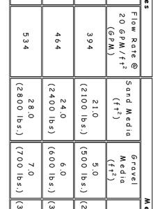
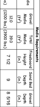
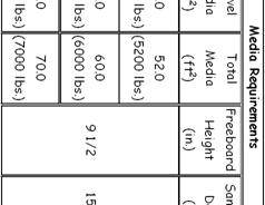
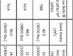
8.2 Steel 13.5 Steel 16.5 Steel 20 Steel 17 FRP 20 FRP Single Systems & 104 S F 120F
 EPD USA, Inc. 1177 West Lincoln Street, Suite 200 Banning, California 92220 Filter Systems 8.2 Steel 13.5 Steel 16.5 Steel 20 Steel 17 FRP 20 FRP Single Systems 138 150 & 104 S104 120 104F 120F Multiple
WARNING. Important Notice
 CAL (Color AquaLuminator ) Light and Return Water Flow for Above Ground Pools Owners Manual IMPORTANT SAFETY INSTRUCTIONS READ AND FOLLOW ALL INSTRUCTIONS SAVE THESE INSTRUCTIONS Table of Contents SECTION
2001 SERIES CRYOGENIC BAR STOCK BODY VALVES
 12501 Telecom Drive, Tampa, FL 33637 Ph: (813) 978-1000 Fax: (813) 977-3329 www.cpc-cryolab.com INSTALLATION, OPERATING, AND MAINTENANCE INSTRUCTIONS 17/4.5.2 Rev. 0 2001 SERIES CRYOGENIC BAR STOCK BODY
Series 820 AWWA Butterfly Valves
 Series 820 AWWA Butterfly Valves Installation, Operation and Maintenance September 2015 SP-820-IOM-0915A Series 820 AWWA Butterfly Valves Installation, Operation and Maintenance Contents General.....3
Installation, Operation and Maintenance Guide II NIBCO High Performance Butterfly Valves Series 6822 and 7822
 Installation, Operation and Maintenance Guide II NIBCO High Performance Butterfly Valves Series 6822 and 7822 Statements: NIBCO High Performance Butterfly Valves, Series 6822 and 7822, have been designed
Model DFR 070/156/220 Rotary Actuator
 Figure 1 DFR 156 TABLE OF CONTENTS General 2 Actuator Assembly 18 Scope 2 Bushing / Yoke Assembly 18 Principles of Operation 2 Spring Barrel Assembly 18 Safety Caution 2 Diaphragm Plate Assembly 20 Specifications
INSTALL MANUAL. FOR ON LINE ORDERING- E Commerce Visit Our Website
 INSTALL MANUAL FOR ON LINE ORDERING- E Commerce Visit Our Website WWW.PRESSUREGUARD.COM Contact Information Technical Support: Chris@pressureguard.com Sales Support: Sales@pressureguard.com By Phone: 615-227-6024
Jandy Pro Series NeverLube and Backwash Valve
 installation and Operation Manual English Jandy Pro Series NeverLube and Backwash Valve FOR YOUR SAFETY - This product must be installed and serviced by a contractor who is licensed and qualified in pool
To ensure proper installation, digital pictures with contact information to before startup.
 Check List for Optimal Filter Performance? There should be no back-pressure on the flush line. A 1 valve should have a 2 waste line, and 2 valve should have a 3 waste line. Do not use rubber hosing or
Instructions for 2-row monitoring only
 Installation Instructions for CaseIH cotton picker models: Instructions for 2-row monitoring only CAUTION: Ensure the model numbers shown above correspond to the machine model. If you receive the incorrect
Premium Dry Freight (Plywood) Door Installation REFERENCE FIGURE 1
 Door Installation REFERENCE FIGURE 1") Premium Dry Freight (Plywood) Door Installation A Premium door can be identified as usually having a two-spring balancer, 2 diameter (nominal) rollers, and end hinges with removable covers. If your Whiting
Premium Dry Freight (Plywood) Door Installation A Premium door can be identified as usually having a two-spring balancer, 2 diameter (nominal) rollers, and end hinges with removable covers. If your Whiting
KEYSTONE. Butterfly valves Figure 9 Installation & Maintenance Instructions. Please read these instructions carefully
 KEYSTONE Please read these instructions carefully This symbol indicates important messages and safety instructions. Hazard potentials: disregarding of instructions improper use of product insufficiently
Fisher 1061 Pneumatic Piston Rotary Actuator with Style H & J Mounting Adaptations
 Instruction Manual 1061 H & J Actuator Fisher 1061 Pneumatic Piston Rotary Actuator with Style H & J Mounting Adaptations Contents Introduction... 1 Scope of Manual... 1 Description... 2 Specifications...
ANDERSON GREENWOOD SERIES 500 PILOT OPERATED SAFETY RELIEF VALVES INSTALLATION AND MAINTENANCE INSTRUCTIONS
 Before installation these instructions must be fully read and understood TABLE OF CONTENTS 1. General valve description and start-up... 1 2. Main valve maintenance... 1 3. Pilot maintenance... 5 4. Pilot
Holley Ford 351W Hi-Ram Modular Intake Manifold Kits
 Holley Ford 351W Hi-Ram Modular Intake Manifold Kits Holley P/N Engine Application & Induction Configuration 300-241 Hi-Ram, 1 x 95mm LS Throttle Body (longitudinal mount) w/ port EFI provisions & fuel
Halsey Taylor Owners Manual
 Halsey Taylor Owners Manual Fully-Recessed Barrier-Free Water Cooler RC RC W/CUP DISPENSER INSTALLER To assure you install these models easily and correctly, PLEASE READ THESE SIMPLE INSTRUCTIONS BEFORE
Installation Instructions
 Installation Instructions Bulletin 237471 MACXLine 8-3/16" Rigid Coaxial Transmission Line Including Inners Only Replacement Systems Revision E Contents Description 1 Components 1 Installation Tool Kit
Meteor Filter System Kit Owner's Manual
 Meteor Filter System Kit Owner's Manual IMPORTANT SAFETY INSTRUCTIONS READ AND FOLLOW ALL INSTRUCTIONS SAVE THESE INSTRUCTIONS Table of Contents SECTION I. Pump Safety Instructions... 2 SECTION II. How
is10 Spa-Side Remote Installation Guide (For IntelliTouch and CP3800 series systems)
") is10 Spa-Side Remote (For IntelliTouch and CP3800 series systems) Installation Guide IMPORTANT SAFETY INSTRUCTIONS READ AND FOLLOW ALL INSTRUCTIONS SAVE THESE INSTRUCTIONS IMPORTANT SAFETY PRECAUTIONS
is10 Spa-Side Remote (For IntelliTouch and CP3800 series systems) Installation Guide IMPORTANT SAFETY INSTRUCTIONS READ AND FOLLOW ALL INSTRUCTIONS SAVE THESE INSTRUCTIONS IMPORTANT SAFETY PRECAUTIONS
FORD POWERSTROKE 6.0L DIESEL ENGINE
 #8 INSTALLATION MANUAL MODEL FP-100 & FP-150 With New Quick Connect Components! 2003-2007 FORD POWERSTROKE 6.0L DIESEL ENGINE Performance Fuel System Parts PLEASE READ THESE INSTRUCTIONS THOROUGHLY BEFORE
Pressure Sensor No Series
 Sales Manual Section 335 PRODUCT SPECIFICATION 84372 SERIES Pressure Sensor No. 84372-Series GENERAL DESCRIPTION The patented* No. 84372-Series Pressure Sensor contains a weatherproof, snap-acting valve
INSTALLATION INSTRUCTIONS
 INSTALLATION INSTRUCTIONS R5 MODULAR WHEEL TO WHEEL NERF STEP BARS APPLICATION: 2007-2019 Chevy Silverado / GMC Sierra 2500-3500 Crew Cab (8ft. Bed) Excl. Dually PART NUMBER: 28-534580, 28-534585 ITEM
Keystone Series GR resilient seated butterfly valves GRW/GRL Installation and operation manual
 Before installation these instructions must be fully read and understood Important Before valves are installed or used the following actions are recommended. 1. Valves/parts have to be inspected and thoroughly
Val-Matic 3-Way Tapered Plug Valve
 Val-Matic 3-Way Tapered Plug Valve Manual No. CCPV-OM4-1 Operation, Maintenance and Installation Manual INTRODUCTION.2 RECEIVING AND STORAGE 2 VALVE CONSTRUCTION..2 DESCRIPTION OF OPERATION. 3 INSTALLATION
Scope. Applicability. Caution. I & M CV3000 Series. Storage. Installation & Maintenance Instructions for Marwin CV3000 Series Three Piece Ball Valves
 I & M CV3000 Series 3170 Wasson Road Cincinnati, OH 45209 USA Phone 513-533-5600 Fax 513-871-0105 marwin@richardsind.com www.marwinvalve.com Installation & Maintenance Instructions for Marwin CV3000 Series
Sentinel 250 Fire Hydrant
 Maintenance Instructions manual table of contents PAGE Sentinel 250 Fire Hydrant Inspection and Lubrication 2 Rotating Hydrant to Face Desired Direction 3 Installing Extension Section 3-6 Restoring Service
IMPORTANT WARRANTY & INSTALLATION INSTRUCTIONS ATTACHED
 IMPORTANT WARRANTY & INSTALLATION INSTRUCTIONS ATTACHED Please Forward All Attached Information to Consumer Warranty Not Valid Unless Returned to CORSA Exhaust STOP Please take time to read and understand
Halsey Taylor Owners Manual
 Halsey Taylor Owners Manual Fully-Recessed Barrier-Free Water Cooler RC RC W/CUP DISPENSER INSTALLER To assure you install these models easily and correctly, PLEASE READ THESE SIMPLE INSTRUCTIONS BEFORE
METERING VALVE 2" STEM GUIDED
 2" STEM GUIDED All Rights Reserved. All contents of this publication including illustrations are believed to be reliable. And while efforts have been made to ensure their accuracy, they are not to be construed
SAND FILTERS. Models: ECSF500, ECSF650, ECSF700, & ECSF800
 SAND FILTERS Models: ECSF500, ECSF650, ECSF700, & ECSF800 FUNCTION The filter uses special filter media to remove dirt particles from pool water. The filter media is loaded into the filter tank and functions
A B C D E F. b.tools Required (supplied by others) 3/16" Drill Bit 3/8" Wrench Phillips Head Screwdriver
 3/16 Drill Bit 3/8 Wrench Phillips Head Screwdriver") Page 1 of 13 5E.1 Parts List a. Below Deck Automatic Retractable Security Cover Kit (1) Tube End Bearing Plate (A) (1) Rope Reel with Motor Attached (B) (1) Rope Reel Cover (C) (1) Cover Drum (1) Cover
Page 1 of 13 5E.1 Parts List a. Below Deck Automatic Retractable Security Cover Kit (1) Tube End Bearing Plate (A) (1) Rope Reel with Motor Attached (B) (1) Rope Reel Cover (C) (1) Cover Drum (1) Cover
Instructions for 2-row monitoring only
 Installation Instructions for CaseIH cotton picker models: Instructions for 2-row monitoring only Ensure the model numbers shown above correspond to the machine model. If you receive the incorrect installation
DYNA OIL COOLER AND THERMOSTAT KIT
 INSTRUCTIONS -J000 REV. 07-5-00 Kit Numbers 6985-0 (Chrome) and 6989-0 (Silver) General DYNA OIL COOLER AND THERMOSTAT KIT These oil cooler kits feature a thermostat built-in to the oil filter mount. These
Installation Manual. Model # SF-4W rev.4 (02/28/14) 1200 Lower River Road, P.O. Box 800 Charleston, TN PULSAR
 1200 Lower River Road, P.O. Box 800 Charleston, TN PULSAR") Installation Manual Model # SF-4W 1200 Lower River Road, P.O. Box 800 Charleston, TN 37310-0800 1-800-4-PULSAR is now a part of www.lonza.com Product Stewardship MAKING THE WORLD A BETTER PLACE Lonza is
Installation Manual Model # SF-4W 1200 Lower River Road, P.O. Box 800 Charleston, TN 37310-0800 1-800-4-PULSAR is now a part of www.lonza.com Product Stewardship MAKING THE WORLD A BETTER PLACE Lonza is
Keystone Butterfly valves ParaSeal Installation and maintenance instructions
 Before installation these instructions must be fully read and understood Please read these instructions carefully Hazard potentials: disregarding of instructions improper use of product insufficiently
Important: Please read these instructions carefully and completely before starting the installation. TITAN Fuel Tanks
 TITAN pt. no.: 01 0000 0129 Important: Please read these instructions carefully and completely before starting the installation. TITAN Fuel Tanks INSTALLATION INSTRUCTIONS G e n e r a t i o n V Extended
INSTALLATION INSTRUCTIONS
 AUTOMOTIVE PRODUCTS, INSTALLATION INSTRUCTIONS HDX DROP STEP WTW APPLICATION: 2007-2017 Chevy Silverado / GM Sierra / 1500-2500-3500 Ext. / Double / Crew Cab - 6.5 Ft Bed PART NUMBER: 56-534575, 56-534595,
User Guide IM/TORBAR-EN Rev. D. Averaging pitot tubes
 User Guide IM/TORBAR-EN Rev. D Torbar The Company We are an established world force in the design and manufacture of measurement products for industrial process control, flow measurement, gas and liquid
INSTALLATION, OPERATION AND MAINTENANCE MANUAL (IOM)
") INSTALLATION, OPERATION AND MAINTENANCE MANUAL (IOM) IOM-1088 03-16 Model 1088 Vacu-Gard Blanketing Valve ISO Registered Company SECTION I I. DESCRIPTION AND SCOPE The Model 1088 Vacu-Gard is a tank blanketing
INSTALLATION, OPERATION AND MAINTENANCE MANUAL (IOM) IOM-1088 03-16 Model 1088 Vacu-Gard Blanketing Valve ISO Registered Company SECTION I I. DESCRIPTION AND SCOPE The Model 1088 Vacu-Gard is a tank blanketing
NEECO INDUSTRIES INC. INSTRUCTION MANUAL 7 1/16 10K SLAB GATE BODY
 INSTRUCTION MANUAL 7 1/16 10K SLAB GATE BODY INTRODUCTION The NF-700 type gate valves provided by Neeco Industries are full-bore through conduit non-rising stem manually (w/ball screw) operated valves.
BEFORE BEGINNING INSTALLATION
 COMPLETE CHASSIS FUEL LINE KITS For 1996-2000 Honda Civic Equipped with B-Series Engine INSTALLATION INSTRUCTIONS PLEASE study these instructions carefully before beginning this installation. Most installations
HAYWARD FLOW CONTROL TBH SERIES TRUE UNION BALL VALVE INSTALLATION, OPERATION AND MAINTENANCE INSTRUCTIONS
 HAYWARD FLOW CONTROL TBH SERIES TRUE UNION BALL VALVE INSTALLATION, OPERATION AND MAINTENANCE INSTRUCTIONS Pg. 1 of 10 PLEASE READ THE FOLLOWING INFORMATION PRIOR TO INSTALLING AND USING HAYWARD TBH SERIES
A B C D E F. Tools Required (supplied by others)
") Page 1 of 17 Parts List Below Deck Automatic Retractable Security Cover Kit (1) Tube End Bearing Plate (A) (1) Rope Reel and Cover Drum Motor Assembly (B) (1) Cover Drum (1) Pulley Support Channel (2)
Page 1 of 17 Parts List Below Deck Automatic Retractable Security Cover Kit (1) Tube End Bearing Plate (A) (1) Rope Reel and Cover Drum Motor Assembly (B) (1) Cover Drum (1) Pulley Support Channel (2)
Installation, operation & maintenance manual Integral Tie Rod Design
 Installation, operation & maintenance manual Integral Tie Rod Design Date: 2431 North Wigwam Dr. Stockton, CA 95205 Phone: 800-344-3246 Fax: 209-943-0242 Email: sales@procoproducts.com Table of Contents
With PA Series Transmission: S101 Series Midship Pumps: With C20 Series Transmission:
 S100 Series C10 Chain Drive Transmission Overhaul Instructions Installation Instructions S100 Series Centrifugal Fire Pumps Issue Date Form No. F 1031 Section 3017 09/25/02 Rev. Date 04/26/13 IL3292 Table
OPERATION AND MAINTENANCE INSTRUCTIONS
 OPERATION AND MAINTENANCE INSTRUCTIONS 334 SERIES THREE-PIECE BALL VALVES 1/4 to 2-1/2 Installation and Operation Always install your valve according to accepted industry standards and practices and operate
Important: Please read these instructions carefully and completely before starting the installation. TITAN Fuel Tanks
 TITAN pt. no.: 01 0000 0119 Important: Please read these instructions carefully and completely before starting the installation. TITAN Fuel Tanks INSTALLATION INSTRUCTIONS G e n e r a t i o n V Extended
Installation, operation & maintenance manual
 Installation, operation & maintenance manual 2431 North Wigwam Dr. Stockton, CA 95205 Phone: 800-344-3246 Fax: 209-943-0242 Email: sales@procoproducts.com Table of Contents 1.0 Introduction 2 2.0 Storage
HIGH PRESSURE CONTROL VALVE R2L ACTUATOR
 R2L ACTUATOR All Rights Reserved. All contents of this publication including illustrations are believed to be reliable. And while efforts have been made to ensure their accuracy, they are not to be construed
CompoSeal butterfly valves, wafer style Installation & Maintenance Instructions
 Please read these instructions carefully This symbol indicates important messages and safety instructions. Intended valve use The valve is intended to be used only in applications within the pressure/temperature
Dual Remote Filtration System Installation and Servicing Instructions
 IMPORTANT NOTICE Read all instructions completely before attempting to install this unit. Improper installation could result in serious system and/or equipment damage. The installation of this system is
KEYSTONE OPTISEAL F14/16-15/17 AND BREWSEAL BUTTERFLY VALVES INSTALLATION AND MAINTENANCE INSTRUCTIONS
 Before installation these instructions must be fully read and understood 4. Ozone: storage rooms should not contain any equipment generating ozone. E.g. lamps, electric motors. IMPORTANT Before valves
PRESSURE REGULATOR BACK PRESSURE TO ATMOSPHERE WITH OUTSIDE SUPPLY
 PRESSURE REGULATOR BACK PRESSURE TO ATMOSPHERE WITH OUTSIDE SUPPLY All Rights Reserved. All contents of this publication including illustrations are believed to be reliable. And while efforts have been
BMK-12. Dual-Gard By-Pass Filter Mounting Kit Installation and Servicing Instructions
 BMK-12 Dual-Gard By-Pass Filter Mounting Kit Installation and Servicing Instructions IMPORTANT NOTICE Read all instructions completely before attempting to install this unit. Improper installation could
DeZURIK " BAW AWWA BUTTERFLY VALVES WITH EPOXY-RETAINED SEAT
 DeZURIK 20 144" BAW AWWA BUTTERFLY VALVES WITH EPOXY-RETAINED SEAT Instruction D10373 April 2017 Instructions These instructions provide information about the 20 (250 F2 model only) and the 24-144 BAW
SWING CHECK VALVES SERIES 52-SC SERIES 600
 SWING CHECK VALVES SERIES 52-SC SERIES 600 FEATURES/BENEFITS/SPECIFICATIONS AMERICAN Flow Control Series 52-SC Swing Check Valves incorporate design features to help increase service life for water and
S6100 SERIES REVERSIBLE PANIC/FIRE EXIT RIM DEVICES INSTALLATION INSTRUCTIONS
 801 Avenida Acaso, Camarillo, Ca. 93012 (805) 494-0622 www.sdcsecurity.com E-mail: service@sdcsecurity.com S6100 SERIES REVERSIBLE PANIC/FIRE EXIT RIM DEVICES INSTALLATION INSTRUCTIONS These instructions
SAE STANDARD BOLT ASSEMBLY NUMBER 60020_IR4 INSTALLATION AND OPERATIONS MANUAL
 SAE STANDARD BOLT ASSEMBLY NUMBER 60020_IR4 INSTALLATION AND OPERATIONS MANUAL CONTENTS Important! Read Carefully... 1 Safety and Warnings... 2 Warning Rotating Equipment Hazard... 2 Warning Pinch Point
<THESE INSTRUCTIONS MUST BE GIVEN TO THE END USER> B&W Trailer Hitches 1216 Hawaii Road / PO Box 186 Humboldt, KS P: F:
 B&W Trailer Hitches 26 Hawaii Road / PO Box 86 Humboldt, KS 66748 P:620.473.3664 F:620.869.903 Ford OEM Mount System Installation Instructions 20,000
MagicStream Laminar. Installation and User s Guide IMPORTANT SAFETY INSTRUCTIONS READ AND FOLLOW ALL INSTRUCTIONS SAVE THESE INSTRUCTIONS
 1 MagicStream Laminar Installation and User s Guide IMPORTANT SAFETY INSTRUCTIONS READ AND FOLLOW ALL INSTRUCTIONS SAVE THESE INSTRUCTIONS 2 IMPORTANT SAFETY PRECAUTIONS Important Notice: Attention Installer:
Installation Instructions
 86-95 Suzuki Samurai HD Transfer Case Mount (SKU# STC-EOS) Revised 4/11/14 Installation Instructions Suggested Tools: CAUTION: Safety glasses should be worn at all times when working with vehicles and
Installation Guide Current Ford F-250 & Ford F-350 Super Duty. Product Code: 109 & 119
 Installation Guide 2008 - Current Ford F-250 & Ford F-350 Super Duty Product Code: 109 & 119 September 1, 2012 Tools Needed Components Included 3/8" Drill P2 Tip #2 Philips Screwdriver 1/2" Drill Bit Hinged
PV4 - Compact Shut Off Style Pig Valve IOM - Installation, Operation & Maintenance
 ACECO Valve P.O. Box 9 Mounds, Oklahoma 74047 PV4 - Compact Shut Off Style Pig Valve IOM - Installation, Operation & Maintenance Doc. No.: IOM-PV4-.0 Date: 6/0-00 Revision: A Contents: Installation Operation
INSTALLATION INSTRUCTIONS STUDIO S
 INSTALLATION INSTRUCTIONS STUDIO S 70.0 MONOBLOCK LAVATORY FAUCET WITH SPEED CONNECT Thank you for selecting American Standard... the benchmark of fine quality for over 00 years. To ensure that your installation
Crispin Valves Operating Guide. Crispin
 Crispin Valves Operating Guide Crispin Since 1905 Crispin Multiplex Manufacturing Co. 600 Fowler Avenue Berwick, PA 18603 1-800-AIR-VALV T: (570) 752-4524 F: (570) 752-4962 www.crispinvalve.com sales@crispinvalve.com
KEYSTONE Figure 990/991 Butterfly valves Installation, operation and maintenance instructions
 Before installation these instructions must be fully read and understood Potentially dangerous practices: disregarding instructions improper use of product use of insufficiently qualified personnel Application
INSTRUCTION MANUAL Kwik Slide
 INSTRUCTION MANUAL Kwik Slide FOR USE WITH 30048 DEALER/INSTALLER: (1) Provide this Manual to end user. (2) Physically demonstrate sliding procedures in this Manual to end user. (3) Have end user demonstrate
NOTE. Installation and Service Manual Dual Planetary Gearmotor Slim Rack Slide Out System
 Installation & Service Manual Slim Rack In-Wall Slide Out System Control Box Part Number 1510000199 Content Copyright LCI/Power Gear Issued: December 2014 #3010002588, Rev. 0E Installation and Service
SpaCommand Spa-Side Remote (For EasyTouch, IntelliTouch and Compool CP3800 Series Control Systems)
") SpaCommand Spa-Side Remote (For EasyTouch, IntelliTouch and Compool CP3800 Series Control Systems) Installation and User s Guide IMPORTANT SAFETY INSTRUCTIONS READ AND FOLLOW ALL INSTRUCTIONS SAVE THESE
SpaCommand Spa-Side Remote (For EasyTouch, IntelliTouch and Compool CP3800 Series Control Systems) Installation and User s Guide IMPORTANT SAFETY INSTRUCTIONS READ AND FOLLOW ALL INSTRUCTIONS SAVE THESE
HIGH PRESSURE CONTROL VALVE PISTON BALANCED
 PISTON BALANCED All Rights Reserved. All contents of this publication including illustrations are believed to be reliable. And while efforts have been made to ensure their accuracy, they are not to be
Model DF269 Control Valve
 Figure 1 DF269 Control Valve TABLE OF CONTENTS Introduction 2 Fail Open Actuator Disassembly 6 General 2 Body and Packing Reassembly 7 Scope 2 Fail Closed Actuator Resassembly 8 Specifications 3 Fail Open
PFadvantage MF 6850/6855; Ideal 9080/9090
 MF 6850/6855; Ideal 9080/9090 Note: Indented items indicate parts included in an Quantity by Model assembly listed above MF Ideal Part Name/Description Part Number 6850 6855 9080 9090 Instruction Kit MF
<THESE INSTRUCTIONS MUST BE GIVEN TO THE END USER> B&W
 B&W Trailer Hitches 6 Hawaii Rd / PO Box 86 Humboldt, KS 66748 P:60.473664 F:60.869.903 Turnoverball Gooseneck Hitch Installation Instructions MODEL 08
Model 6518FR. NOTE TO INSTALLER: Please leave this information with the Maintenance Department. LIMITED WARRANTY
 INSTALLATION, OPERATION & MAINTENANCE INSTRUCTIONS 1455 Kleppe Lane Sparks, NV 89431-6467 (775) 359-4712 Fax (775) 359-7424 E-mail: haws@hawsco.com website: www.hawsco.com Model 6518FR No. 2077777(21)
IOM Manual. IOM Manual. Series 76/77.
 IOM Manual IOM Manual Series 76/77 www.flowlinevalves.com Flow Line Valve and Controls, L.L.C. 110 Main Project Road Schriever, LA 70395 P.O. Box 677 Schriever, LA 70395 Phone 985-414-6004 * Toll Free
INSTALLATION INSTRUCTIONS
 INSTALLATION INSTRUCTIONS COOLANT EXPANSION TANK FORD FOCUS Document: 19-0151 Support: info@radiumauto.com WARNINGS: DO NOT WORK ON THE COOLANT SYSTEM WHEN THE ENGINE IS AT OPERATING TEMPERATURE. WAIT
DELTA O-RING CARTRIDGE SEAL ASSEMBLY AND INSTALLATION INSTRUCTIONS INTRODUCTION:
 DELTA O-RING CARTRIDGE SEAL ASSEMBLY AND INSTALLATION INSTRUCTIONS INTRODUCTION: These instructions are provided to familiarize the user with the seal and its use. The instructions must be read carefully
WARNING!! C-659 SUBKIT FIGURE 4
 '0-'0 DODGE / TON TRUCKS '03-' DODGE 3/ & TON TRUCKS (WILL FIT /, 3/ & TON MEGA CAB SHORT BED) WARNING!! BRAKE, FUEL, AND ELECTRICAL LINES MAY NEED TO BE LOOSENED OR REPOSITIONED TO PROVIDE CLEARANCE FOR
AEROMOTIVE Part # Subaru Fuel Rails for Top Feed Injectors WRX & STI INSTALLATION INSTRUCTIONS
 AEROMOTIVE Part # 14135 Subaru Fuel Rails for Top Feed Injectors 02-14 WRX & 07-14 STI INSTALLATION INSTRUCTIONS CAUTION: Installation of this product requires detailed knowledge of automotive systems
ISOBUS Down Force Hydraulics Kinze
 Important Notices Please carefully follow these step-by-step instructions. If you have questions, contact at 515-232-5363 x 1. Direction words (LEFT and RIGHT) are commonly used when describing an installation
Easy Riser swing check valve Models E-1 & F-1
 Page 1 of 7 1. DESCRIPTION The Viking Easy Riser Swing Check Valve is a general purpose rubber-faced approved for use in fire service systems. The valve is for use in wet system risers, preaction system
2-row and All-row systems included.
 Ag Leader Technology Cotton Picker Installation Installation Instructions for John Deere cotton picker models: 2-row and All-row systems included. IMPORTANT: Ensure the model numbers shown above correspond
354 CHAPTER EIGHT WATER PUMP
 354 CHAPTER EIGHT 33 Shift handle F : Forward N : Neutral R : Reverse proper alignment of the water tube to the water pump opening during each installation attempt. Make sure the locating pins enter the
Single Nozzle Systems UNIVERSAL NOZZLE SYSTEM INSTRUCTIONS Part #'S 00-1XXXXX
 INTRODUCTION Thank you for purchasing the highest quality nitrous system on the market. Nitrous Outlet strives to offer the best product with the best price and customer service available. Nitrous Outlet
INSTALLATION & OWNER S MANUAL
 Rev. B, p. 1 of 25 INSTALLATION & OWNER S MANUAL POLARIS RANGER RCS (for models XP or HD) (for model years 2009-) cab without doors kit (p/n 1POLRCWD) cab with doors kit (p/n 1POLRC) doors only kit (p/n
CAMSHAFT TIMING CHAIN, SPROCKET, AND TENSIONER REPLACEMENT
 Page 1 of 45 CAMSHAFT TIMING CHAIN, SPROCKET, AND TENSIONER REPLACEMENT Special Tools J 45027 Tensioner Tool J 45059 Angle Meter Page 2 of 45 Removal Procedure Page 3 of 45 Page 4 of 45 Page 5 of 45 Fig.
Bypass / Filter Feeders Operations & Maintenance Manual
 Bypass / Filter Feeders Operations & Maintenance Manual Record Your Model, Serial Number and Other Information on the back of this document. Manufacturing: Bypass & Filter Feeders, Glycol Feed Packages,
INSTALLATION INSTRUCTIONS
 INSTALLATION INSTRUCTIONS ----3300 W. Pontiac Way Clovis, CA 93612 toll free: 1-800-445-3767 web: www.belltech.com---- 6605-6607 FLIP KIT CHEVROLET C/K 1500 / 2500 PICK UP Thank you for being selective
INSTALLATION INSTRUCTIONS WHEEL-TO- WHEEL
 INSTALLATION INSTRUCTIONS WHEEL-TO- WHEEL AUTOMOTIVE PRODUCTS, INC. APPLICATION: SILVERADO/ SIERRA 2014-20 00 CREW CAB (5.5 FT BED) 2014-20 00/2500/3500 CREW CAB (6.5FT BED) & DUAL REAR WHEEL (8FT BED)
EC4 SERIES CRYOGENIC VALVES 1/4 2 Sizes
 12501 Telecom Drive, Tampa, FL 33637 Ph: (813) 978-1000 Fax: (813) 977-3329 www.cpc-cryolab.com INSTALLATION, OPERATING, AND MAINTENANCE INSTRUCTIONS 17/2.5.6 Rev. 0 EC4 SERIES CRYOGENIC VALVES 1/4 2 Sizes
½ DODGE CUMMINS
 15 June 2016 #1050305D 2003-2004½ Dodge Cummins FlowMAX Lift Pump Kit (I-00169) - 1-2003-04½ DODGE CUMMINS BD FLOWMAX LIFT PUMP KIT Installation Instructions P/N# 1050305D PLEASE READ ALL INSTRUCTIONS
DEUBLIN. DEUBLIN Unions H57 H67 H87
 Instructions for Installation and Maintenance Installation Instructions For DEUBLIN H57 H67 H87 19.4.2013 DEUBLIN Italiana S.r.l. Via Guido Rossa, 9 40050 Monteveglio (BO) Italy ++39.051.835611 Fax: ++39.051.832091