Instructions Manual Roytronic Série P + Electronic Metering pumps
|
|
|
- Nora Goodman
- 5 years ago
- Views:
Transcription


 232-683-000")

1 Instructions Manual Roytronic Série P + Electronic Metering pumps 10. Grande Rue Pont Saint Pierre (FRANCE) TEL: +(33) FAX: +(33) Lit# /2007
2 For file reference, please record the following data: Model No. : Serial Nr: Installation Date:: Installation Location: When ordering replacement parts for your LMI Metering Pump or Accessory, please include complete Model Number and Serial Number of your unit. DE ES FR GB Carefully read and understand all precautions before installing or servicing any metering pump IT NL PT
3 Contents 1.0 Precautions Introduction Specifications Unpacking check list Installation Pump location and installation Pump mounting Flooded suction Suction lift - Wall bracket mount Suction lift - Tank mount Suction lift - Shelf mount Tubing connections Four-Function Valves (4-FV) Four-Function Valve Installation FastPrime Foot valve/suction tubing installation Injection check valve and discharge tubing installation Operation Control panel Start-up and adjustment Start-up/Priming for FastPrime heads Start-up/Priming for pump supplied with 4-FV Start-up/Priming without 4-FV Output adjustment Total pump output Calibration in Internal mode Calibration in External mode Methods of externally triggering or pacing P + 3 P + 7, and P Spare Parts Replacement and routine maintenance Depressurizing the discharge line (for pumps equipped with a 4-FV only) Depressurizing the discharge line (for single ball FastPrime heads only) Liquifram (Diaphragm) replacement Cartridge valve and O-Ring replacement Injection check valve parts replacement FastPrime valve O-Ring replacement Stroke length setting replacement EPU wiring diagram Liquid end parts list Troubleshooting Annex : Figures... I - XI 3
4 PRECAUTIONS 1.0 PRECAUTIONS The following precautions should be taken when working with LMI metering pumps. Please read this section carefully prior to installation. Protective Clothing ALWAYS wear protective clothing, face shield, safety glasses and gloves when working on or near your metering pump. Additional precautions should be taken depending on the solution being pumped. Refer to MSDS precautions from your solution supplier. Water Pre-Prime All LMI pumps are pre-primed with water when shipped from the factory. If your solution is not compatible with water, disassemble the Pump Head Assembly. Thoroughly dry the pump head, valves, seal rings, balls and Liquifram (diaphragm). Reassemble head assembly tightening screws in a crisscross pattern. Refill the pump head with the solution to be pumped before priming the pump. (This will aid in priming.) Solution Compatibility Determine if the materials of construction included in the liquid handling portion of your pump are adequate for the solution (chemical) to be pumped. LMI pumps are tested by NSF for use on muriatic acid and sodium hypochlorite. Always refer to the solution supplier and the LMI Chemical Resistance Chart for compatibility of your specific LMI metering pump. Contact your local LMI distributor for further information. Tubing Connections Inlet and outlet tubing or pipe sizes must not be reduced. Outlet tubing size must not be increased. Make certain that any tubing is SECURELY ATTACHED to fittings prior to start-up (see Section., Tubing Connections). ALWAYS use LMI supplied tubing with your pump, as the tubing is specifically designed for use with the pump fittings. It is recommended that all tubing be shielded and secure to prevent possible injury in case of rupture or accidental damage. If tubing is exposed to sunlight, black UV resistant tubing should be installed. Check tubing frequently for cracks and replace as necessary.. Vinyl Tubing Your carton may contain a roll of clear vinyl tubing; this is only for connection to the return line of the FastPrime Head and must not be used as discharge tubing. Fittings and Machine Threads All LMI pumps have straight screw machine threads on the head and fittings and are sealed by the O-rings. DO NOT use Teflon tape or pipe dope to seal threads. Teflon Tape may only be used on the 1/2" NPT thread side of the Injection Check Valve, the stainless steel liquid end connections, or if piping is directly connected to the pipe threads of the suction or discharge fittings. Plumbing Always adhere to your local plumbing codes and requirements. Be sure installation does not constitute a cross connection. Check local plumbing codes for guidelines. LMI is not responsible for improper installations. Back Pressure/Anti-syphon valve If you are pumping downhill or into low or no pressure system, a back pressure/antisyphon device such as LMI s Four-Function Valve should be installed to prevent overpumping or syphoning. Contact your LMI distributor for further information. Electrical Connections WARNING: To reduce the risk of electrical shock, the metering pump must be plugged into a properly grounded grounding-type receptacle with ratings conforming to the data on the pump control panel. The pump must be connected to a good ground. Do not use adapters! All wiring must conform to local electrical codes. If the supply cord is damaged, it must be replaced by the manufacturer, stocking distributor, or authorized repair center in order to avoid a hazard. Line Depressurization To reduce the risk of chemical splash during disassembly or maintenance, all installations should be equipped with line depressurization capability. Using LMI s Four-Function Valve (-FV) is one way to include this feature. Ground Fault Circuit Interrupter WARNING: To reduce the risk of electric shock, install only on a circuit protected by a Ground Fault Circuit Interrupter (GFCI). 4

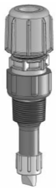
5 INTRODUCTION 2.0 Introduction LMI is the world s most versatile manufacturer of economical and efficient metering pumps. This manual addresses the installation, maintenance and troubleshooting procedures for manually and externally controlled pumps. LMI has a worldwide network of stocking representatives and authorized repair centers to give you prompt and efficient service. Please review this manual carefully. Pay particular attention to warnings and precautions. Always follow good safety procedures, including the use of proper clothing, eye and face protection. This manual is for Roytronic Series P + pumps. 2.1 Spécifications P + XX1 & P + XX8 Operating temperature 14 to 113 F 10 to 45 C P + XX2 to P + XX7 14 to 113 F 10 to 45 C Voltage 110 to 120 V 220 to 240 V Frequency 50 to 60 Hz 50 to 60 Hz Max. Current 0.66 A 0.34 A Wattage 39 W 42 W Fuse Specification 1.25 AHT (5 x 20 mm) 1.25 AHT (5 x 20 mm) 2.2 Unpacking check list Your carton will contain many or all of the following items. Please notify the carrier immediately if there are any signs of damage to the pump or its parts. - Metering pump (See annex fig. 1) - Foot valve (See annex fig. 2) - Vinyl tubing (for Fastprime TM ) (See annex fig. 3) - Ceramic foot valve weight (See annex fig. 4) - Injection check - valve (See annex fig. 5) - Four-Function Valve(Optional) (See annex fig. 6) 5
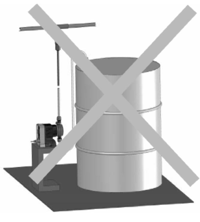
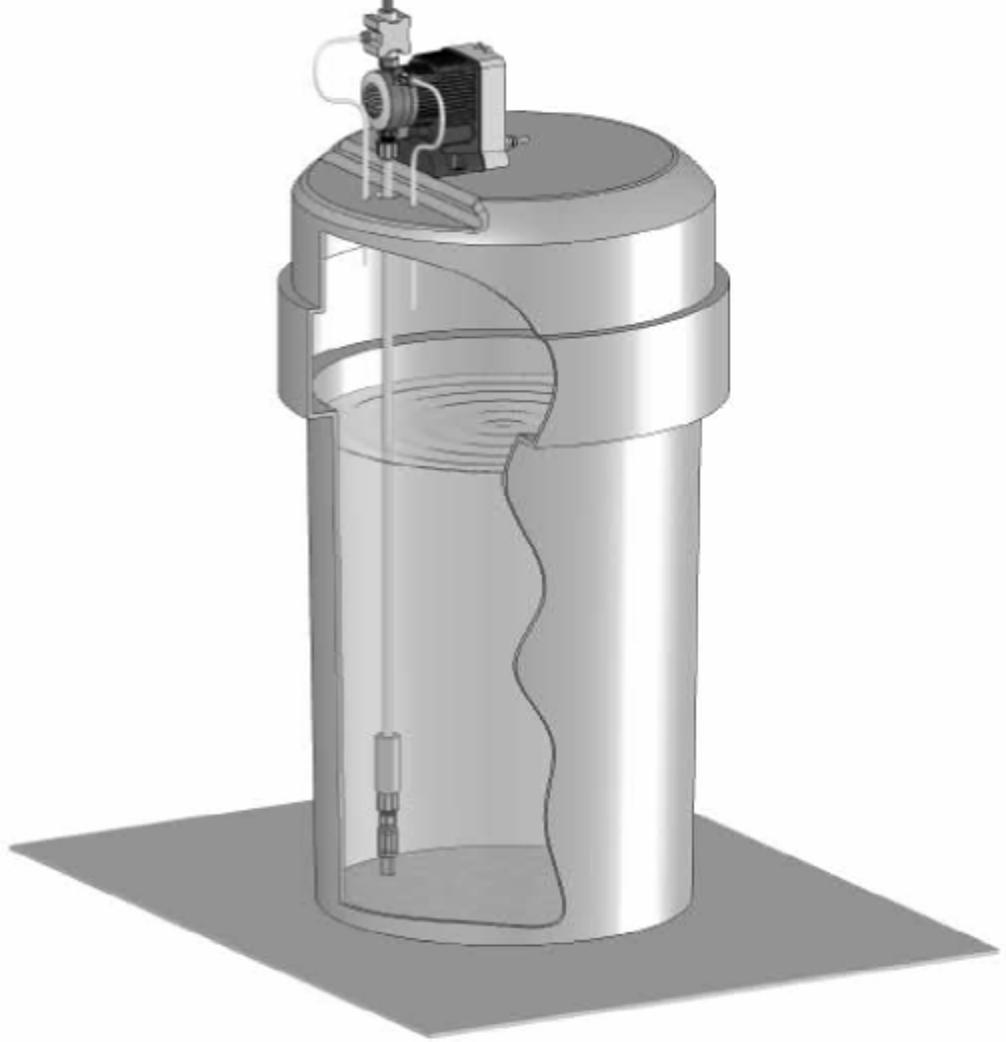
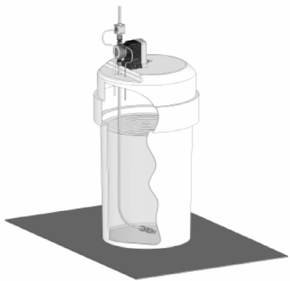
6 INSTALLATION 3.0 Installation 3.1 Pump Location and Installation Locate pump in an area convenient to solution tank and electrical supply. The pump should be accessible for routine maintenance, and should not be operated in ambient temperatures above 113 F (45 C). If the pump will be exposed to direct sunlight, LMI black, UV resistant tubing should be installed. 3.2 Pump Mounting The pump can be mounted in one of two ways: A. FLOODED SUCTION (ideal installation); or B. SUCTION LIFT - when suction lift is less than 5 feet (1.5 m) for solutions having a specific gravity of water or viscosity of less than 100 cst (centistokes). For denser or more viscous solutions, consult distributor. Your LMI metering pump must be mounted so that the suction and discharge valves are vertical. NEVER position pump head and fittings horizontally Flooded Suction For flooded suction the pump is mounted at the base of the storage tank. This installation is the most trouble-free, and is recommended for very low outputs, solutions that gasify, and highviscosity solutions. Since the suction tubing is filled with solution, priming is accomplished quickly and the chance of losing prime is reduced. A foot valve is not necessary in a flooded suction installation. When pumping downhill or into low or no pressure system, a back pressure/anti-syphon device should be installed to prevent overpumping or syphoning. Although popular for all solutions, LMI recommends flooded suction installations for all highviscosity fluid applications. - INCORRECT (See annex fig. 7) - CORRECT (See annex fig. 8) Suction Lift - Wall Bracket Mount The pump may be mounted using an LMI Wall Mount Bracket Assembly directly above the solution tank. A pump mounted in this manner allows for easy changing of solution tanks or drums Suction Lift - Tank Mount The pump may be mounted on a molded tank provided there is a recess to keep the pump stationary Suction Lift - Shelf Mount The pump may be mounted on a shelf (customer supplied) maintaining a suction lift of less than 5 ft (1.5 m). (See annex fig. 9 and fig. 10) 6
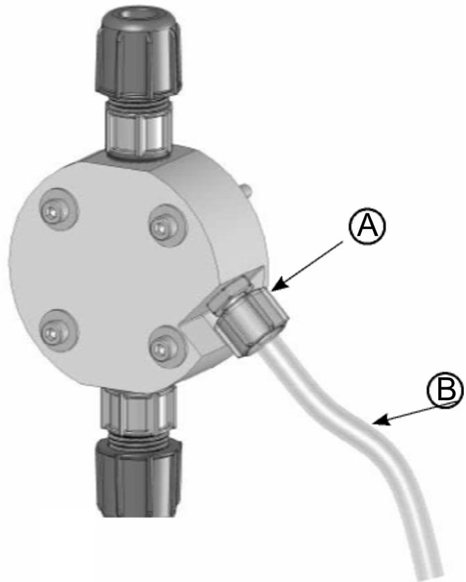
7 INSTALLATION 3.3 Tubing Connections A. Use only LMI tubing. B. DO NOT USE CLEAR VINYL TUBING ON THE DISCHARGE SIDE OF THE PUMP. The pressure created by the pump can rupture vinyl tubing, which is only for connection to the return line of the FastPrime fitting. C. Before installation, all tubing must be cut with a clean square end. D. Valve and head connections from the factory are capped or plugged to retain pre-prime water. Remove and discard these caps or plugs before connecting tubing. DO NOT USE PLIERS OR PIPE WRENCH ON COUPLING NUTS OR FITTINGS. To assemble tubing into the fittings: 1. Put coupling nut (A) over tubing. 2. Press on tubing sleeve (B) about one inch (25 mm). 3. For 1/4" or 6mm tubing, (10mm) tubing protrudes from the sleeve (B). For all other tubing push tube to the bottom of groove in end cap (C). 4. Tighten the coupling nut (A) onto the fitting (D). Legend figure : (See annex fig. 11) A : Coupling nut C : End cap D : Fitting B : Tubing sleeve 3.4 Four-Function Valves (4-FV) Your pump may be equipped with a 4-FV, or standard discharge valve. If your pump is not equipped with a four-function valve and you feel it is needed in your application, it can be purchased as an accessory. Contact your local LMI stocking distributor. The features of a 4-FV are listed below. (see fig.12 13) 1. Pressure Relief: If the discharge line is over pressurized, the valve opens sending solution back to the supply tank. 2. Line Depressurization: Opening the relief knob provides line drain back to the supply tank. 3. Anti-Syphon: Prevents syphoning when pumping solution downhill or into a vacuum. 4. Back Pressure: Supplies approximately 1.7 bars (25 psi) back pressure to prevent overpumping when little or no system back pressure is present. 3.5 Four-Function Valve Installation To install the 4-FV, remove valve housing and upper cartridge screw in the valve and hand tighten. An additional 1/8-1/4 turn may be necessary to prevent leakage mm. (1/4") tubing connects to the side of the valve and acts as a return line to the solution tank. To ensure priming, this tubing must NOT be submerged in the solution. Legend figure : (See annex fig. 14) A : 6.35 Tubing, B.:Connector, C.:Discharge, D.:To solution tank or drum, E.:Bottom tubing in fitting Push and hold while tightening connector, F.:To Pump Head This return line tubing must be secured to ensure pumped solution will safely return to supply tank 7
8 INSTALLATION 3.6 FastPrime TM valve The FastPrime Head is equipped with a valve that allows for opening the head to atmospheric pressure. When installing a pump equipped with a FastPrime Head connect the 3/8" outer diameter clear vinyl tubing provided with the pump to the barbed nozzle. Route the vinyl return line back to the solution tank. This tubing must not be submerged in the solution. FastPrime TM system (See annex fig. 15) 3.7 Foot Valve/Suction Tubing Installation The Foot Valve acts as a check valve to keep the pump primed in suction lift applications. The foot valve is designed to be submersed in the solution tank or drum and must sit in a vertical position at the bottom. Position approximately 2 inches (50 mm) off the bottom if the tank or drum contains sediment. The ceramic weight, when installed, helps position the foot valve in a vertical position. Pump models equipped with high viscosity liquid ends are not equipped 1. Attach the foot valve to one end of the suction tubing (see Tubing Connections, Section 3.3). 2. Slide the ceramic weight over the tubing end until it contacts the top of the foot valve coupling nut. 3. Place foot valve and tubing into the solution tank. Check that the foot valve is vertical and approximately 2 inches (50 mm) from the bottom of the tank or drum (see illustration). Connect the other end of the tubing to the suction side of the pump head (bottom side) (see Tubing Connections, Section.3.3). - INCORRECT Tilted sideways will not prime (See annex fig. 16) - CORRECT Foot valve must remain vertical Legend figure : (See annex fig. 17) A : Return lines must not B : Use ceramic weight be submerged C : 2.0 in. (50 mm) for sediment accumulation 3.8 Injection Check Valve and Discharge Tubing Installation The Injection Check Valve prevents backflow from a treated line. Install the injection check valve at the location where chemical is being injected into the system. Any size NPTF fitting or pipe tee with a reducing bushing to 1/2" NPTF will accept the injection check valve. Use Teflon tape or pipe dope to seal the pipe threads only. When installing the Injection Check Valve, be sure to position it so that the valve enters the bottom of your pipe in a vertical position. Variations left and right within 40 are acceptable (see illustration). After cutting an appropriate length of tubing, connect tubing to the injection check valve then back to the discharge side of the pump head. Make sure it does not crimp or come into contact with hot or sharp surfaces (see Tubing Connections, Section 3.3.). Typical injection check valve installation Legend figure : (See annex fig. 18) A : 1" Pipe tee. B : Reduction 1' to 1/2". C : Injection check valve. D : Flow E : CORRECT Use Teflon tape here on pipe threads only. F : Do NOT use Teflon tape on machined threads. G : 40 Variation acceptable. H : Injection check valve. I : Flow. 8
9 OPERATION 4.0 Operation 4.1 Control panel (Fig. 19) 1. Power/Mode Selection Button: This button allows convenient starting and stopping of the pump. For pumps with external control capability (P + 3, P + 7, P + 8) this button switches pump operation between internal and external modes. When operating in internal mode the Pulse Indicator Light will flash green. When operating in external mode the Pulse Indicator Light will flash yellow. 2. Speed Adjustment Knob: This knob provides adjustment of the stroking speed. For pumps with this knob (P + 1, P + 7, P + 8) turning this knob clockwise increases stroke frequency (speed) from a minimum of 1 stroke per minute. 3. Stroke Adjustment Knob: This knob provides adjustment of the stroke length. Turning this knob clockwise increases the stroke length, which results in a higher amount of chemical displaced per stroke. It is recommended that the stroke range stay between 20% and 100%. 4. Pulse Indicator Light: This light will flash green when pumping in internal mode, and will flash yellow when pumping in external mode. The light is on between strokes and off during the actual stroke. 5. Low-Level Indicator Light: This light will turn red when a Low-Level Sensor registers a low chemical level. This will turn off the pump. You must have a Low-Level Sensor connected to the pump through the Low-Level Connector for this function to operate. 6. Low-Level Connector (3-Pin) Fig.20: This connector is for the connection of a Low-Level Sensor (48413). The low-level switch input connections are always active for all models in all functional modes. If the fluid level drops below the level specified by the Low-Level Sensor, the pump will stop and the Low-Level Indicator Light will turn on. The pump is designed to recognize an open circuit as full, and a closed circuit as empty. The pin functions are as follows: 1. Low level signal 3. No connection 4. Low level return 7. External Control Connector (5-Pin)Fig.21: This connector is for the connection of various options and accessories that can be used to externally control the pump. The pin functions (and the wire color for the standard LMI external control cable) are as follows: 1. Remote On/Off Signal (Brown) 2. Ground/Common (White) 3. External pulse signal (Blue) (used only with P + 3, and P + 7 pumps) Volt DC. Supply voltage (Black) mA, input signal (Green/Yellow) (used only with P + 8 pumps). Some of the accessories available for use with P+ Series metering pumps are listed below. Note that an Adapter Cable (48488) is needed when connecting any of the MICROPACE(TM) units (Fig.23). A. MICROPACE A/D Converter (MP-100) - for translating a -20 milliamp signal into pulses. B. MICROPACE Divider (MP-400D) - for reducing the frequency of high frequency pulses. C. MICROPACE Multiplier (MP-500M) - for increasing the frequency of low frequency pulses. D. Pulse Transmitter (48489) - for pulsing in time with another LMI Electronic Metering Pump. E. RFP Flowmeter and Programmable Divider - for pacing the stroke frequency off of the system flow. F. FC Flowmeter/Contactor - for pacing the stroke frequency from the system flow. 9
 or less and the steps below are followed Pumps are shipped from the factory with water in the pump head to aid in priming. 4.2.")
10 OPERATION 4.2 Start-up and Adjustment The pump is normally self-priming if suction lift is 5 ft (1.5 m) or less and the steps below are followed Pumps are shipped from the factory with water in the pump head to aid in priming Start-Up/Priming for FastPrime Heads Read this entire section completely before proceeding. When all precautionary steps have been taken, the pump is mounted, and the tubing is securely attached, you may now start priming the pump. 1. Plug in or switch the pump on. 2. While the pump is running, set the Speed Adjustment Knob and the Stroke Adjustment Knob at 100%. 3. Turn The FastPrime knob 1 to 2 turns counter-clockwise. 4. The suction tubing should begin to fill with solution from the tank. 5. A small amount of solution will begin to discharge out the return line of the FastPrime valve. Once this happens, turn the knob clockwise P until hand tight and SHUT THE PUMP OFF. 6. The pump is now primed. 7. Proceed to output adjustment, Section Start-Up/Priming for Pump Supplied with 4-FV Read this entire section completely before proceeding. If the pump does not self-prime, remove the 4-FV on the discharge side of the pump head. Remove the check valve and for water or solution into the port until the head is filled. Replace valve,then follow start up/priming steps When all precautionary steps have been taken, the pump is mounted, and the tubing is securely attached, you may now start priming the pump. 1. Plug in or switch the pump on. 2. While the pump is running, set the Speed Adjustment Knob and the Stroke Adjustment Knob at 100%. 3. 1/4 turn open the relief side (black knob) of the 4-FV. 4. The suction suction tubing should begin to fill with solution from the tank. 5. A small amount of solution will begin to discharge out the return line of the 4-FV. Once this happens, 1/4 turn or release the knob and SHUT THE PUMP OFF. 6. The pump is now primed. 7. Proceed to output adjustment, Section Start-Up/Priming for without 4-FV If the pump does not self-prime, remove the discharge check valve and pour water or solution into the port until the head is filled. Replace valve, then follow start up/priming steps Read this entire section completely before proceeding. When all precautionary steps have been taken, the pump is mounted, and the tubing is securely attached, you may prime the pump. 1. Plug in or switch on the pump. 2. While the pump is running, set the speed knob and the stroke knob at 100%. 3. The suction tubing should begin to fill with solution from the tank. 4. Once the solution begins to exit the pump head on the discharge side, SHUT THE PUMP OFF. 5. The pump is now primed. 6. Proceed to output adjustment, Section
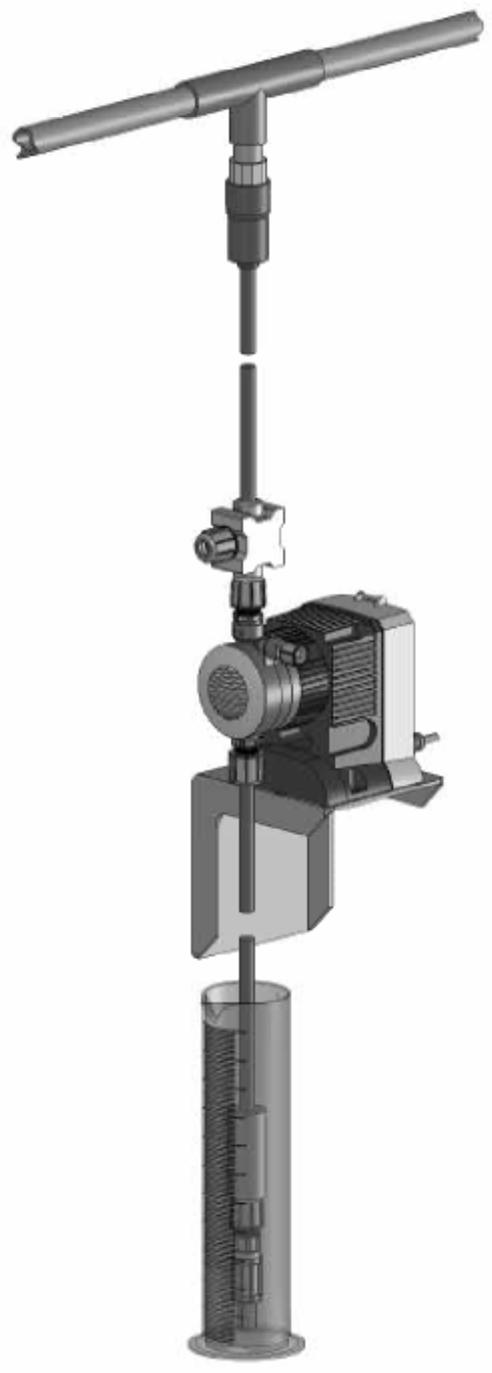
11 4.3 Output Adjustment Once the pump has been primed, an appropriate output adjustment MUST be made. Pump output should be calculated and adjustments made accordingly Total Pump Output Calculate the approximate output of the pump as follows: OPERATION PUMP OUTPUT = MAX PUMP OUTPUT x % SPEED x % STROKE When converting between different units, remember these conversion factors: 1 Gallon = liters 1 Day = Minutes 240 SPM = SPH Use Max Output (from data plate on side of pump) = 1 GPH (1 gallon per hour). If the pump is set at 60% speed and 70% stroke length, the approximate pump output is: 1.0 x 0.60 x 0.70 = 0.42 GPH. Multiply by 24 (hours in one day) to calculate in gallons per day. If pump is not equipped with speed adjustment, calculate by Max Pump Output x % Stroke length only Calibration in Internal Mode Once installation is complete and the approximate output has been determined, the pump should be calibrated to adjust speed and stroke for your actual desired output. (Calibration cylinders may be purchased from your local LMI distributor) 1. Be sure the pump is primed, and discharge tubing and Injection Check Valve are installed as they would be in normal service (i.e., including factors such as injection pressure, fluid viscosity, and suction lift). 2. Place the Foot Valve in a graduated container with a volume of 1000 ml or more. 3. Plug in and switch pump to Internal Mode. Pump until all the air is exhausted from the suction line and head. 4. Turn the pump off. Refill graduated container to a level starting point. 5. Using a stopwatch or timer, turn the pump on for a measured amount of time (120 pump strokes minimum). The longer the time period is, the more confident you can be of the results. Be sure to count the number of strokes during the calibration period when making comparisons. 6. Turn the pump off. Note the time elapsed in relation to volume displaced in the graduate. Now, calculate the output in the time unit you choose (minutes, hours, days, etc.). 7. If the output is too low or too great, use the Stroke Adjustment Knob and/or the Speed Adjustment Knob to fine-tune the amount of flow, estimating required correction and repeat steps 1-. (See annex fig. 22) 11
12 OPERATION Calibration in External Mode It may be helpful to decrease the speed of the pump in order to count the number of strokes. For accuracy count at least 120 strokes 1. Be sure the pump is primed, and discharge tubing and injection check valve are installed as they would be in normal service (i.e., including factor such as injection pressure, fluid viscosity and suction lift). 2. Place the foot valve in a graduated container with a volume of 100 ml or more. 3. Plug in and switch pump to internal mode. Pump until all the air is exhausted from the suction line and head. 4. Switch pump OFF and refill graduate to a starting point. 5. Switch pump ON and count the number of strokes for exactly one minute, then switch pump OFF. 6. Note volume pumped during the calibration period of one minute. Divide into this the number of strokes to determine the volume of solution pumped per stroke. Example: 720 ml in 240 strokes = 3.0 ml per stroke. Multiply this by your expected stroke rate per minute, per hour or per day and compare with desired output requirements. 7. Turn Stroke Adjustment Knob to your best estimate of required correction and repeat calibration procedure. 4.4 Methods of Externally Triggering or Pacing P + 3, P + 7, and P + 8 Pumps Method of Triggering P + 3, and P + 7 Pumps Through External Control Connector 1. Switch Closure Switch closing triggers pump 2. NPN Transistor Base goes high to trigger pump 3. PNP Transistor Base goes low to trigger 4. Opto Isolator *PIN Switch or transistors must be capable of switching 24V DC at 15 ma. Minimum time in low impedance state (ON) is 25 milliseconds. Minimum time in high impedance state (OFF) is 50 milliseconds. To operate in external mode, contact between 1 and 2 (Brown/white) must be closed. *PIN / Wire color: 2 = White 3 = Blue 12

13 OPERATION The default configuration for the Remote On/Off input is: open contacts pump stopped, closed. Therefore pins 1 and 2 of the External Control Connector must be shorted together in external mode for the pump to respond to external signals. These pumps have two operating modes: Local (Pulse Indicator Light flashes green) and Remote (Pulse Indicator Light flashes yellow). Pressing the Power/ Mode Selection Button switches between Local and Remote modes. The default configuration for operating mode is Local mode. When the pump is in Local mode the Remote On/Off input is ignored. When the pump is in Remote mode the Remote On/Off input is always monitored. The pump will return to the last power mode if power is interrupted Control Modes Local Mode When in Local mode the P + 3 pump runs continuously at maximum speed When in Local mode P + 7 and P + 8 pumps run at the speed indicated by the speed knob Remote Mode (for P + 3, and P + 7) In Remote mode pulses occurring faster than a rate of 1200 pulses per minute (less than 50 ms) and pulses with a duration of less than 25 ms are ignored. Pulses occurring between 240 strokes per minute (SPM) and 1200 pulses per minute results in the pump running at 240 SPM. Pulses occurring at less than 240 SPM results in the pump stroking at that rate Remote Mode (for P + 8) In Remote mode the pump speed is controlled by a milliamp (ma) Analog Input signal. The factory default settings for the Analog Input are: 20mA input = maximum speed, 4mA = 0 stroke per minute. The ma input setting can be calibrated to any level between 0 22 ma. When recalibrating the input settings, the span between high and low input must be greater than 6mA. If the span is not large enough, the Pulse Indicator Light will flash green and yellow alternately at about 10 times per second. In the default settings, the fast level ma input is greater than the slow level ma input. This is known as direct action. In direct action when the ma input is at or above the setting for the fast level, the pump will run at maximum speed. When the ma input is below the setting for the slow level, the pump will stop. Reverse action is when the slow level ma input is greater than the fast level ma input. In reverse action when the ma input is at or below the setting for the fast level, the pump will run at maximum speed. When the ma input is above the setting for the slow level, the pump will stop. (See ) Calibrating the Analog Input Settings (for P + 8) 1. Press and hold the Power/Mode Selection Button for more than 5 seconds. The pump stops. 2. Turn the Speed Adjustment Knob completely clockwise P to enter the fast level analog input state. The Pulse Indicator Light will flash 1 second green 1/4 second yellow. 3. Apply the desired fast level analog signal and press the Power/Mode Selection Button for less than 3 seconds. The Pulse Indicator Light will be green for 1 second before resuming flashing to confirm storage of the setting. 4. Turn the Speed Adjustment Knob completely counter-clockwise Q to enter the slow level analog input state. The Pulse Indicator Light will flash 1 second yellow 1/4 second green. 5. Apply the desired slow level analog signal and press the Power/Mode Selection Button for less than 3 seconds. The Pulse Indicator Light will be yellow for 1 second before resuming flashing to confirm storage of the setting. 6. To return the pump to the factory default settings turn the Speed Adjustment Knob to 50%. The Pulse Indicator Light should flash 1 second green, 1 second yellow. Then press the Power/Mode Selection Button. 7. To exit calibration mode press and hold the Power/Mode Selection Button for more than 3 seconds. 13
14 MAINTENANCE 5.0 Spare Parts Replacement and Routine Maintenance LMI recommends replacing the elastomeric components of the pump on an annual basis. Refer to the LMI Metering Pump Price List for the proper Spare Parts Kit or RPM Pro Pac kit number or contact your local LMI stocking distributor. 5.1 Depressurizing the Discharge Line (for Pumps Equipped with a 4-FV Only) ALWAYS wear protective clothing, face shield, safety glasses and gloves when performing any maintenance or replacement on your pump. To reduce the risk of chemical splash during disassembly or maintenance, all installations should be equipped with line depressurization capability. Using LMI s Four-Function Valve (4-FV) is one way to include this feature Read steps 1 and 2 below before proceeding. 1. Be sure the Injection Check Valve is properly installed and is operating. If a shut off valve has been installed downstream of the Injection Valve, it should be closed. Be sure your relief tubing is connected to your 4-FV and runs back to your solution drum or tank. 2. Turn the black knob on the 4-FV 1/4 turn. Pull out and hold the yellow knob for a few seconds. The discharge line is now depressurized. Keep both valve knobs open until solution drains back down the discharge tubing into solution drum or tank. Then release the yellow knob, and 1/4 turn the black knob to normal position. 5.2 Depressurizing the Discharge Line (for Single-Ball FastPrime Heads Only) ALWAYS wear protective clothing, face shield, safety glasses and gloves when performing any maintenance or replacement on your pump. Read steps 1 and 2 below before proceeding. 1. Be sure the Injection Check Valve is properly installed and is operating. If a shut off valve has been installed downstream of the Injection Valve, it should be closed. Be sure your relief tubing is connected to your FastPrime valve and runs back to your solution drum or tank. 2. Turn the FastPrime knob one-and-a-half turns counter-clockwise. The discharge line is now depressurized. Keep valve open until solution drains back down the discharge tubing into solution drum or tank. Then turn the knob clockwise P to tighten knob to closed position. 14
15 MAINTENANCE 5.3 Liquifram (Diaphragm) Replacement ALWAYS wear protective clothing, face shield, safety glasses and gloves when working near or performing any maintenance or replacement on your pump. See MSDS information from solution supplier for additional precautions 1. Carefully depressurize, drain, and disconnect the discharge line (see previous sections in this manual). 2. Place the Foot Valve into a container of water or other neutralizing solution. Turn the pump on to flush the head assembly. Once the pump head has been flushed, lift the Foot Valve out of the solution and continue to pump air into the pump head until the pump head is purged of water or neutralizing solution. If the liquid cannot be pumped due to Liquifram rupture, carefully disconnect the suction and discharge tubing using protective clothing, gloves and face shield. Remove the four screws and washers from the head and immerse the head in water or other neutralizing solution. Legend figure : (See annex fig. 24) A : Liquid end. B : Diaphragm. C: Adaptation. D :Shaft seal. E : Drive. 3. Start the pump. While running, set the Stroke Adjustment Knob to 0% and turn the pump off. 4. With the unit off, unscrew the Liquifram by carefully grasping the outer edge and turning it counter-clockwise. Discard old Liquifram. Remove the Adapter Disk (located behind the Liquifram ) and ensure that the diameter of the raised section is the same as the diameter of the replacement Liquifram. 5. Remove Adapter Disk and check condition of the Shaft Seal. Replace Shaft Seal if necessary. 6. Replace the Adapter Disk so that the drain hole of the disk is oriented downward, and the mounting holes line up with the mounting holes of the pump. 7. Screw on the new Liquifram clockwise until turned all the way in. Start the pump and turn the stroke knob to 100%. Stop the pump. 8. Remount the pump head using the four screws and washers. Tighten in a criss-cross pattern. After one week of operation, recheck the screws and tighten if necessary. Be careful not to scratch the Teflon face of the new Liquifram. 15
16 MAINTENANCE 5.4 Cartridge Valve and O-ring Replacement ALWAYS wear protective clothing, face shield, safety glasses and gloves when working on or performing any maintenance or replacement on your pump. See MSDS information from solution supplier for additional precautions. Refer to the LMI Metering Pump Price List for the proper Spare Parts Kit or RPM Pro Pac kit number or contact your local LMI stocking distributor. 1. Carefully depressurize and disconnect the discharge line (see Section 5.1 or 5.2 in this manual). 2. Place the Foot Valve into a container of water or other neutralizing solution. Turn the pump on to flush the head assembly. Once the pump has been flushed, lift the Foot Valve out and continue to pump to let air into the pump head until pump is purged of water or neutralizing solution. If the liquid cannot be pumped due to Liquifram rupture, carefully disconnect the suction and discharge tubing using protective clothing, gloves and face shield. Remove the four screws and washers from the head and immerse the head in water or other neutralizing solution. Spare part replacement kits include specific instructions for valve replacement. Please follow the instructions included with the replacement kit. 3. Carefully disconnect one tubing connection and fitting at a time, then remove and replace the worn valve and O-rings. If necessary, carefully loosen stuck valves by prying side to side using a small screwdriver through the center hole of the valve. Before disassembling the check valves, note the orientation of the valve. 4. Install new check valves in each location. Ensure that the cartridges are oriented correctly. 5.5 Injection Check Valve Parts Replacement Depressurize and drain pipeline (or isolate Injection Check Valve point using valves) so that Injection Check Valve can safely be disassembled. 1. Isolate Injection Check Valve and depressurize pipe or drain pipeline. 2. Carefully depressurize and disconnect the discharge line (see section 5.1 or 5.2 in this manual) Before disassembling the check valve, note the orientation of the parts. 3. Install a new spring, seat, ball, and O-ring. Ensure that the parts are oriented correctly. Legend figure : (See annex fig. 25) A: Spring. B: Ball. C: O-Ring. D: Seat. E: Injection check valve fitting. 16
17 MAINTENANCE 5.6 FastPrime Valve O-Ring Replacement Depressurize and drain pipeline (or isolate Injection Check Valve point using valves) so that Injection Check Valve can safely be disassembled. ALWAYS wear protective clothing, face shield, safety glasses and gloves when performing any maintenance or replacement on your pump. Refer to the LMI Metering Pump Price List for the proper Spare Parts Kit or RPM Pro Pac kit number or contact your local LMI stocking distributor. 1. Be sure the Injection Check Valve is properly installed and is operating. If a shut off valve has been installed downstream of the Injection Valve, it should be closed. 2. Turn the FastPrime Knob one-and-a-half turns counter-clockwise Q. This will depressurize the head. Keep valve open. Carefully remove the return line by gently pulling tubing and moving it from side to side to gradually back tubing off of the barbed fitting. 3. Hold return line tubing upright until solution drains back into solution drum or tank. 4. Using a 11/16" (or 17 mm) socket or wrench remove the Retaining Nut, and pull out the entire FastPrime Valve assembly. Remove and replace the two small O-rings. 5. Reinsert the FastPrime Valve assembly and retighten the Retaining Nut. (17 mm or 11/16" wrench) Then turn the FastPrime Knob clockwise to tighten knob to closed position. 6. Recut 1 to 2 inches off the tip of the return line and ensure the end is squared. Press the return line tubing on completely past the barbs. Legend figure : (See annex fig. 26) A E : O-Rings B H : FastPrime valve 5.7 Stroke Length Replacement C F : Nut D : Knob I : Tubing G : Retaining ring The Stroke Adjustment Knob is calibrated for each pump, and does not need to be removed during Liquifram replacement or during most other maintenance. If the Stroke Knob is removed for any reason it becomes necessary to reset the stroke length. Follow the procedure below to approximate the proper factory setting. 1. Install a new Stroke Shaft. Note that there will be some resistance as the O-ring slides into the control panel. The Stroke Knob can be used to turn the Stroke Shaft. Continue to turn the Stroke Shaft until there is no longer any diaphragm movement. It may be necessary to turn on the pump in order to get the Stroke Knob completely forward; however, care should be taken to ensure that the Stroke Shaft is contacting the Plunger before turning on the unit. Otherwise the pump could be damaged. 2. Once the Stroke Shaft is completely forward, you can reset the stroke length. a. On P + X5, P + X6, and P + X9 pumps press in the Stroke Knob so that the Stroke Knob Pointer indicates 0 (zero). b. For P + X1, P + X4, and P + X8 pumps press the Stroke Knob in at 50 and turn the knob to point at 100. Then remove the Stroke Knob and reinsert so that the Stroke Knob Pointer is indicating 50 again. 3. Use a Phillips head screwdriver to install the Stroke Knob Screw. 4. Insert the Stroke Knob Pointer into the Stroke Knob. Legend figure : (See annex fig. 27) A : Stroke knob pointer. B : Screw. C : Knob. D : O-Ring. E : Shaft. 17
18 MAINTENANCE 5.8 EPU Wiring Diagram Legend figure : (See annex fig. 28) A : Pulser. R : Power cord. W : White or Blue. B : Black or Brown. L : Green or Green/Yellow. Y : Yellow. 5.9 Liquid End Parts List Description 10 Pump head 20 Single ball check valve fitting 25 Double ball check valve fitting 30 Coupling nut 40 Tube connectin O-Ring 90 Seat O-Ring 100 Cartridge valve O-Ring 140 FastPrime Valve gasket 150 FastPrime Valve O-Ring 180 Liquid End cover 190 Liquifram 200 Injection valve seat 210 Injection ball 220 Injection spring 230 Injection check valve body 240 Injection flapper valve 250 Ceramic weight 260 Foot valve body 270 Foot valve strainer 601 FastPrime discharge check valve 602 Suction check valve 603 Cartrigde valve 604 FastPrime cartridge valve 605 FastPrime valve 606 Liquid End hardware 607 Foot valve 608 Injection valve 609 Autoprime discharge valve 611 Autoprime valve 612 Autoprime cartridge 613 Connection kit 615 Valve body - Injection valve (See annex fig. 29A) - Foot Valve (See annex fig. 29B) - Machined FastPrime TM liquid end (See annex fig. 30) - Molded FastPrime TM liquid end(see annex fig. 31) - AutoPrime TM liquid end (See annex fig. 32) 18
19 TROUBLESHOOTING 6.0 Troubleshooting PROBLEM POSSIBLE CAUSE SOLUTION Pump Will Not Prime 1. Pump not turned on or plugged in 1. Turn on pump/plug in pump. 2. Output dials not set properly 2. Always prime pump with speed and stroke at 100%. 3.. Foot Valve not in vertical position on bottom of tank 3. Foot Valve must be vertical (see Foot Valve Installation, Section 3.7). 4. Pump suction lift too high 4. Maximum suction lift is 5 ft (1.5 m). Pumps with High Viscosity Liquid Handling Assemblies require flooded suction. 5. Suction tubing is curved or coiled in tank. 5. Suction tubing must be vertical. Use LMI ceramic weight supplied with pump (see Section 3.7). 6. Fittings are over tightened. 6. Do not over tighten fittings. This causes seal rings to distort and not seat properly which causes pump to leak back or lose prime. 7. Air trap in suction valve tubing. 7. Suction tubing should be as vertical as possible. AVOID FALSE FLOODED SUCTION! (see Section 3.2.1). 8. Too much pressure at discharge. (Pumps without multi-function valve.) 8. Shut off valves in pressurized line. Disconnect tubing at injection check valve (see Priming Section 4.2). When pump is primed, reconnect discharge tubing. Pump Loses Prime 1. Solution container ran dry. 1. Refill container with solution and reprime (see Section 4.2). 2. Foot Valve is not in a vertical position on the bottom of the tank. 2. Foot Valve must be vertical (see Foot Valve Installation, Section 3.7). 3. Pump suction lift is too high. 3. Maximum suction lift is 5 ft (1.5 m). Pumps with High Viscosity Liquid Handling Assemblies require flooded suction. 4. Suction tubing is curved or coiled in tank. 4. Suction tubing must be vertical. Use LMI ceramic weight supplied with pump (see Section 3.7). 5. Fittings are over tightened. 5. DO NOT OVERTIGHTEN FITTINGS. This causes seal rings to distort and not seat properly which caused pump to leak back or lose prime. 6. Air trap in suction valve tubing. 6. Suction tubing should be as vertical as possible. AVOID FALSE FLOODED SUCTION! (see Section 3.7). 19
20 TROUBLESHOOTING 6.0 Troubleshooting PROBLEM POSSIBLE CAUSE SOLUTION Leakage at tubing 1. Worn tubing ends. 1. Cut about 1 in (25 mm) off tubing and then replace as before 2. Loose or cracked fitting. 2. Replace fitting if cracked. Carefully hand tighten fittings. DO NOT USE PIPE WRENCH. An additional 1/8 or 1/4 turn may be necessary 3. Worn seal rings. 3. Replace balls and seal rings (see Section 5.4) 4. Solution attacking Liquid Handling Assembly 4. Consult your local distributor for alternate materials Low Output or Failure to Pump Against Pressure 1. Pump s maximum pressure rating is exceeded by injection pressure.. 1. Injection pressure cannot exceed pump s maximum pressure. See pump data plate 2. Worn Seal Rings. 2. Worn seal rings or cartridge valves may need replacement (see Section 5.4). 3. Ruptured Liquifram. 3. Replace Liquifram (see Section 5.3). 4. Incorrect stroke length. 4. Recalibrate Output (see Section 4.3.2) 5. Tubing run on discharge may be too long. 5. Longer tubing runs may create frictional losses sufficient to reduce pump s pressure rating. Consult factory for more information. 6. Clogged Foot Valve strainer. 6. Remove Foot Valve strainer when pumping slurries or when solution particles cause strainer to clog. Failure to Run 1. Pump not turned on or plugged in 1. Turn on or plug in pump 2. EPU failure. 2. Disassemble pump and measure the resistance of the EPU across the EPU wires. Consult supplier or factory. (see Section 5.8). 3. Pulser failure. 3. The pulser should be replaced if EPU checks out OK. Consult supplier or factory Excessive Pump Output 1. Syphoning. (Pumping downhill without a multi-function valve). 1. Move injection point to a pressurized location or install an LMI 4-FV (see Section 3.4). 2. Little or no pressure at injection point. 2. If pressure at injection point is less than 25 psi (1.7 Bar), an LMI 4-FV should be installed (see Section 3.4). 3. Excessive strokes per minute. Set pulse rate to proper value. 20


21 7.0 ANNEX F1 F2 F3 F4 F5 F6 F7 F8 I

22 7.0 ANNEX F9 F10 F11 II


23 7.0 ANNEX F12 F13 F14 F15 F16 F17 III


24 7.0 ANNEX F18 F19 F20 F21 F22 IV


25 7.0 ANNEX F23 F24 F25 V

26 7.0 ANNEX F26 F27 VI
27 7.0 ANNEX F28 F29A F29B VII
28 7.0 ANNEX F30 VIII
29 7.0 ANNEX F31 IX
30 7.0 ANNEX F32 X
31 7.0 ANNEX F33 XI
32
Instruction Manual Series A Electronic Metering Pumps
 Instruction Manual Series A Electronic Metering Pumps For file reference, please record the following data: Model No: Serial No: Installation Date: Installation Location: When ordering replacement parts
ROYTRONIC Series A Electronic Metering Pumps Instruction Manual Manual No : 2002 Rev. : D Rev. Date : 12/2016
 ROYTRONIC Series A Electronic Metering Pumps Manual No : 2002 Rev. :D Rev. Date : 12/2016 ROYTRONIC SERIES A Model A 7 5 1-8 2 8 S I Model Code Configuration Control Code 1- Dual Manual Control: Speed
Instruction manual EXCEL Series AD
 Instruction manual EXCEL Series AD 10. Grande Rue 27360 Pont Saint Pierre (FRANCE) TEL: +(33) 232-683-000 FAX: +(33) 232-683-093 www.miltonroy-europe.com Lit# 2024.C 5/2012 For file reference, please record
For file reference, please record the following data:
 Instruction Manual Electronic Metering Pumps! CAUTION Carefully read and understand all precautions before installing or servicing any metering pump.! CAUTION For file reference, please record the following
Basic Instruction Manual for AA, B, C, E, J5 and P Pumps
 Basic for AA, B, C, E, J5 and P Pumps Manual No : 1615 Rev. : U Rev. Date : 02/2017 PRECAUTIONS The following precautions should be taken when working with LMI metering pumps. Please read this section
Instruction Manual. ROYTRONIC EXCEL Series AD Electronic Metering Pumps
 Instruction Manual ROYTRONIC EXCEL Series AD Electronic Metering Pumps For file reference, please record the following data: Model No: Serial No: Installation Date: Installation Location: When ordering
ROYTRONIC EXCEL Series AD Electronic Metering Pumps Instruction Manual Manual No : 2024 Rev. : E Rev. Date : 11/2015
 ROYTRONIC EXCEL Series AD Electronic Metering Pumps Manual No : 2024 Rev. : E Rev. Date : 11/2015 sales@novatech-usa.com www.novatech-usa.com Tel: (866) 433-6682 Fax: (866) 433-6684 Tel: (281) 359-8538
Instruction Manual. Series E7 Metering Pumps. For file reference, please record the following data:
 Instruction Manual Series E7 Metering Pumps For file reference, please record the following data: Model No: Serial No: Installation Date: Installation Location: When ordering replacement parts for your
Uni-Dose. For file reference, please record the following data:
 For file reference, please record the following data: Model No: Serial No: Installation Date: Installation Location: When ordering replacement parts for your Pump or Accessory, please include the complete
Instruction Manual. Series E7 Metering Pumps. For file reference, please record the following data:
 Instruction Manual Series E7 Metering Pumps For file reference, please record the following data: Model No: Serial No: Installation Date: Installation Location: When ordering replacement parts for your
E.R.I.C. Series Electronic Metering Pump Installation & Operation Manual (Enhanced Control) Manual No.: Revision : 00 Rev.
 Manual No.: Revision : 00 Rev.") E.R.I.C. Series Electronic Metering Pump Installation & Operation Manual (Enhanced Control) Manual No.: 54189 Revision : 00 Rev. Date: 03/2016 Note: This manual is a supplement to 54038 Table of Contents
E.R.I.C. Series Electronic Metering Pump Installation & Operation Manual (Enhanced Control) Manual No.: 54189 Revision : 00 Rev. Date: 03/2016 Note: This manual is a supplement to 54038 Table of Contents
PUMP OUTPUT = MAX PUMP OUTPUT x % SPEED x % STROKE
 OPERATION 4.2.3 Start-Up/Priming for AutoPrime Heads (LE-XXXAX or LE-XXXHX) 4.3 Output Adjustment 4.3.1 Total Pump Output Read this entire section completely before proceeding. When all precautionary steps
Instruction Manual Series HH Electronic Metering Pumps
 Instruction Manual Series HH Electronic Metering Pumps!! CAUTION CAUTION Carefully read and understand all precautions before installing or servicing any metering pump. For file reference, please record
Manual. MicroTron. Series C. Installation Maintenance Repair Manual. Chemical Metering Pump
 Manual MicroTron Series C Chemical Metering Pump Installation Maintenance Repair Manual Advantage Controls P.O.Box 1472 Muskogee, OK 74402 Phone: 800-743-7431 Fax: 888-686-6212 www.advantagecontrols.com
MicroTron Series C. Manual. Installation Maintenance Repair. Manual. Chemical Metering Pump
 Manual MicroTron Series C Chemical Metering Pump Installation Maintenance Repair Manual Advantage Controls P.O.Box 1472 Muskogee, OK 74402 Phone: 800-743-7431 Fax: 888-686-6212 www.advantagecontrols.com
EH Series High Viscosity Electronic Metering Pumps Instruction Manual
 EH Series High Viscosity Electronic Metering Pumps Instruction Manual Five Boynton Road Hopping Brook Park Holliston, MA 01746 USA TEL 508-429-1110 FAX 508-429-7433 WEBSITE: www.iwakiamerica.com Notice
Instruction Manual. Series R Peristaltic Pump. For file reference, please record the following data:
 Instruction Manual Series R Peristaltic Pump For file reference, please record the following data: Model No: Serial No: Installation Date: Installation Location: When ordering replacement parts for your
Proteus Series Electronic Metering Pump Installation & Operation Manual Manual No.: Revision : 02 Rev. Date : 07/2017
 Proteus Series Electronic Metering Pump Installation & Operation Manual Manual No.: 54038 Revision : 02 Rev. Date : 07/2017 Note: For enhanced control features see manual 54189 Proteus TM Series Model
Manual. MicroTron. Series B. Installation Maintenance Repair. Manual. Chemical Metering Pump
 Manual MicroTron Series B Chemical Metering Pump Installation Maintenance Repair Manual Advantage Controls P.O. Box 1472 Muskogee, OK 74402 Phone: 800-743-7431 Fax: 888-686-6212 www.advantagecontrols.com
Instruction Manual. This Manual should be made available to persons responsible for Installation, Operation and Maintenance. Pump Model No...
 MILTON ROY INDIA (P) LTD. Metering Pumps Instruction Manual M -Series This Manual should be made available to persons responsible for Installation, Operation and Maintenance. M- Pump Model No... Serial
INSTALLATION INSTRUCTIONS FOR THE TRUCK MOUNTED VIPER ADDITIVE INJECTION SYSTEM GTP-8776C
 INSTALLATION INSTRUCTIONS FOR THE TRUCK MOUNTED VIPER ADDITIVE INJECTION SYSTEM GTP-8776C This additive injection system was designed to be used with five gallon jug of additive. The system is supplied
Fisher 657 Diaphragm Actuator Sizes and 87
 Instruction Manual 657 Actuator (30-70 and 87) Fisher 657 Diaphragm Actuator Sizes 30 70 and 87 Contents Introduction... 1 Scope of Manual... 1 Description... 2 Specifications... 2 Installation... 3 Mounting
READ ALL CAUTIONS CAREFULLY BEFORE INSTALLING PUMP SEE PAGE (4) SERIES 100/150 INSTRUCTION MANUAL P/N CDE: IM120 E/07
 SERIES 100/150 INSTRUCTION MANUAL P/N CDE: IM120 E/07") READ ALL CAUTIONS CAREFULLY BEFORE INSTALLING PUMP SEE PAGE (4) SERIES 100/150 P/N 32040 CDE: IM120 E/07 INSTRUCTION MANUAL TABLE OF CONTENTS Page SAFETY INSTRUCTIONS... 2 INTRODUCTION... 3 PRECAUTIONS
READ ALL CAUTIONS CAREFULLY BEFORE INSTALLING PUMP SEE PAGE (4) SERIES 100/150 P/N 32040 CDE: IM120 E/07 INSTRUCTION MANUAL TABLE OF CONTENTS Page SAFETY INSTRUCTIONS... 2 INTRODUCTION... 3 PRECAUTIONS
IWAKI AMERICA EHC/EHE-FF Series Electronic Metering Pump Instruction Manual
 IWAKI AMERICA EHC/EHE-FF Series Electronic Metering Pump Instruction Manual INSTRUCTION MANUAL Notice 2004 Iwaki America Inc. Five Boynton Road, Holliston, MA 01746 USA tel (508) 429-1440 fax (508) 429-1386
Distributed by: M&M Control Service, Inc
 Metering Diaphragm Pumps by Blue-White Industries TM Series Built -In DFD Diaphragm Failure Detection (see page 7) Series F and V Variable Speed Positive Displacement Diaphragm Metering Pump ProSeries
Series A. Series A. Model A S I
 Series A Model A 7 5 1-8 2 8 S I Model Code Configuration Control Code 0 Single Manual Control: Speed (stroking frequency) fixed and stroke length manually adjustable 1 Dual Manual Control: Speed (stroking
Excel AD Electromagnetic dosing pump
 Flow rate Up to 7.6 l/h Pressure Up to 17.3 bar Liquid ends Acrylic, stainless steel, PP, PVC, PVDF, designed for viscous products, designed for degassing products LCD user interface with display of the
Dosing Pump Operational Manual
 Chemical Dosing Specialists Dosing Pump Operational Manual Pump Range WMPSP0110 - WMPSP0408 - WMPSP0607 - WMPSP0805 - WMPSP1204 - WMPSP1502 - WMPSP2001 1- Product Introduction 2 1.1 Product Overview 2
1/2" AIR DRIVEN DIAPHRAGM PUMP
 1/2" DRIVEN DIAPHRAGM PUMP OPERATION AND SERVICE GUIDE O-1225D NOV. 2008 Page 1 of 6 Refer to Bulletin P-605, Parts List P-9151 DRIVEN, DOUBLE DIAPHRAGM PUMP MANUAL Congratulations on purchasing one of
D/G-03 Maintenance. Shutdown Procedure During Freezing Temperatures. Daily. Periodically
 D/G-03 Maintenance NOTE: The numbers in parentheses are the Ref. Nos. on the illustrations in the Parts Manual. Daily Check the oil level and the condition of the oil. The oil level should be 3/4 in. (20
Chem-Feed Installation Instructions
 Chem-Feed Installation Instructions Model C-800, Noir Jr. Positive Displacement Injector Pump PT SARANA PRIMA ENGUNA Jl.Gunung Sahari Raya 84 C Jakarta Phn. 021 4200045 Fax. 021 4200483 www.spe.co.id 80000-211
EHE Series Electronic Metering Pump Instruction Manual
 EHE Series Electronic Metering Pump Instruction Manual Five Boynton Road Hopping Brook Park Holliston, MA 01746 USA TEL 508-429-1110 FAX 508-429-7433 Website: www.walchem.com Notice 2007 WALCHEM Corporation
Solenoid Chemical Metering Pump. Operating Manual
 Series S Solenoid Chemical Metering Pump CheckPoint Headquarters CheckPoint UK CP Pumps & Systems FZE 21356 Marion Lane C2/C3 Lombard Centre P.O. Box 262131 Mandeville, Louisiana 70471 Kirkhill Place,
Model FMBC3000 Series Operating Instructions. Drum Pump Flow Meter
 Model FMBC3000 Series Operating Instructions Drum Pump Flow Meter Table of Contents Safety... 1 Introduction... 1 Specificatons... 1 Features... 1 Section 1 - Installation... 2 Section 2 - Operation...
INSTALLATION/OPERATION/MAINTENANCE INSTRUCTIONS FOR ARCHON MODELS WD2010L, WD2010, WD2010H WASHDOWN STATIONS. ARCHON Industries, Inc.
 ARCHON Industries, Inc. Washdown Stations Models WD2010L, WD2010, WD2010H Installation / Operation / Maintenance Instructions 1 This manual has been prepared as an aid and guide for personnel involved
Electronic Metering Pumps Series C, C PLUS, A PLUS, E, E-DC, E PLUS and HV
 Electronic Metering Pumps Series C, C PLUS, A PLUS, E, E-DC, E PLUS and HV Installation Operation Maintenance Instruction READ ALL WARNINGS CAREFULLY BEFORE INSTALLING TABLE OF CONTENTS 2 Page 0 SAFETY
Precision-24 Manual & Specification
 Precision-24 Manual & Specification 1 Product Introduction... - 1-1.1 Product Overview... - 1-1.2 Technical Parameter...- 2-1.2.1 General Parameter...- 2-1.2.2 Performance Parameter... - 3-1.2.3 Installation
OWNER S MANUAL EVOLUTION 3500, 4500, 5500, & 8500 SERIES PUMPS
 OWNER S MANUAL EVOLUTION 3500, 4500, 5500, & 8500 SERIES PUMPS IMPORTANT SAFETY INSTRUCTIONS When installing and using this electrical equipment, basic safety precautions should always be followed, including
VSP SERIES Installation, Operation and Maintenance Manual
 VSP SERIES Installation, Operation and Maintenance Manual VARIABLE SPEED PERISTALTIC METERING PUMPS VSP-12 and VSP-20 Models READ ALL WARNINGS CAREFULLY BEFORE INSTALLING PUMP PUMP DATA/SPECIFICATIONS
AIR/HYDRAULIC INJECTION GUN MODEL INSTRUCTIONS
 I. OPERATION & DESCRIPTION The Air / Hydraulic Injection Gun is a high-pressure tool that should be used with caution and according to these instructions. IMPORTANT: The Gun is 0,000 psi rated. Do not
SAFETY MANUAL READ FIRST!
 966-05-XX SAFETY MANUAL READ FIRST! IMPORTANT: READ THESE WARNINGS AND SAFETY PRECAUTIONS PRIOR TO INSTALLATION OR OPER- ATION. FAILURE TO COMPLY WITH THESE INSTRUC- TIONS COULD RESULT IN PERSONAL INJURY
Air Operated Double Diaphragm Pump. M-Pump ½ Metallic Non Metallic Pump INSTALLATION, OPERATION & MAINTENANCE MANUAL
 Air Operated Double Diaphragm Pump M-Pump ½ Metallic Non Metallic Pump INSTALLATION, OPERATION & MAINTENANCE MANUAL 0.5 I.O.M rev 05. 12/2015 INDEX Title Section Introduction.1 Safety.2 Warranty, General
Industrial Turbo Meters, Sizes 2" through 6"
 Industrial Turbo Meters Sizes 2" through 6" TUR-UM-00530-EN-19 (October 2014) User Manual Industrial Turbo Meters, Sizes 2" through 6" User Manual CONTENTS Scope of the Manual 5 Specifications 5 Product
SERIES PC INSTRUCTION AND OPERATION MANUAL
 MEGGA SERIES PC INSTRUCTION AND OPERATION MANUAL Models PCT and PCF Close-coupled and frame-mounted single-stage horizontal end-suction pumps. WARNING: Read this manual before installing or operating this
D-04/G-04 Maintenance
 D-04/G-04 Maintenance NOTE: The numbers in parentheses are the Ref. Nos. on the illustrations in the Parts Manual. Daily Check the oil level and the condition of the oil. The oil level should be 1/4 in.
PowerFlo 20 Parts List/Assembly Instructions/Users Guide ***PLEASE READ ALL INSTRUCTIONS CAREFULLY AND THOROUGHLY***
 PowerFlo 20 Parts List/Assembly Instructions/Users Guide ***PLEASE READ ALL INSTRUCTIONS CAREFULLY AND THOROUGHLY*** Owners Manual (Please check to make sure to locate all parts before assembly.) 11/12/2008
IMPORTANT SAFETY INSTRUCTIONS
 Installation & Parts Manual PRO SERIES PUMP IMPORTANT SAFETY INSTRUCTIONS When installing and using this product, basic safety precautions should always be followed, including:! Wear protective clothing,
Model 8329 Table of Contents
 SERVICE & OPERATING MANUAL Original Instructions Instructions Sheet: 670991 Model 8329 Table of Contents Engineering Data and Temperature Limitations... 1 Performance Curve... 2 Dimensions... 3 Metric
MODEL NO. UTL-60-7
 5301400 MODEL NO. UTL-60-7 12 Volt Skid Mounted Utility Sprayer ASSEMBLY / OPERATION INSTRUCTIONS / PARTS ASSEMBLY The sprayer is fully assembled at the factory. The only assembly necessary is to thread
LIQUIDYNAMICS Light Viscosity Bulk Transfer Cart
 This manual contains important warnings and information. READ AND KEEP FOR REFERENCE. LIQUIDYNAMICS Light Viscosity Bulk Transfer Cart Instruction & Parts Manual This Manual Covers P/N 33271 P/N 33271
Manual. Master Acid Injection System. Installation Maintenance Repair Manual. Model DEMA Ag 0960-A
 Manual Master Acid Injection System Model DEMA Ag 0960-A Installation Maintenance Repair Manual 11/2013 1 DEMA Ag pump Instruction & Maintenance Manual Table of Contents Contents Page I. Introduction...3
INSTALLATION, OPERATION, AND MAINTENANCE MANUAL
 INSTALLATION, OPERATION, AND MAINTENANCE MANUAL MODEL 4D-200 REDUCED PRESSURE PRINCIPLE (RPZ) & MODEL 4D-700 REDUCED PRESSURE DETECTOR ASSEMBLY (RPDA) BACKFLOW PREVENTERS 2 ½ 10 Conbraco Industries Inc.
Manual. MicroTron. Series A. Installation Maintenance Repair Manual. Chemical Metering Pump
 Manual MicroTron Series A Chemical Metering Pump Installation Maintenance Repair Manual Advantage Controls P.O. Box 1472 Muskogee, OK 74402 Phone: 800-743-7431 Fax: 888-686-6212 www.advantagecontrols.com
HALLMARK INDUSTRIES INC
 Performance Part No. HP. CONVERTIBLE JET PUMP USER S MANUAL GPH of Water @ Total Discharge Pressure of 40 psi Max. Pressure Max suction (shallow well) Max Suction (deep well) Max GPM (@0 head) Max Discharge
Operation and Maintenance Manual
 BM / BMA Hydrometers ½ Operation and Maintenance Manual i This manual is intended for use by the users of this equipment. The information contained herein is the property of the Arad Ltd. Dalia and may
Series 957, 957N, 957Z, 957RPDA, 957NRPDA, 957ZRPDA
 Series 957, 957N, 957Z, 957RPDA, 957NRPDA, 957ZRPDA Reduced Pressure Zone Assemblies Reduced Pressure Detector Assemblies Sizes: 2 1 2" 10" (65 250mm) Installation Service Repair Kits Maintenance RP/IS-957/957RPDA
MECHANICAL FUEL METER. FM-100 and FM-200 Series Owner s Manual
 MECHANICAL FUEL METER FM-100 and FM-200 Series Owner s Manual To the owner Congratulations on receiving your GPI Mechanical Fuel Meter. We at GPI are pleased to provide you with a fuel meter designed to
SOLAROY 12 VDC Metering Pump
 SOLAROY 12 VDC Metering Pump INSTALLATION, OPERATION, AND MAINTENANCE MANUAL MODEL NUMBER: SR-1PS-TC250 and SR-1PS-TC375 Manual #23858 Revision 2/2012 Precautions / Warnings: Proper fuse installation (to
Excellence through Versatility
 Metering Pumps Excellence through Versatility Liquid Metronics Incorporated has been providing quality products and service to the water treatment industry worldwide for over 25 years. Leading the way
Operating Instructions ProMinent Low Flow Dual Metering Pump (S-2) Dosing Package
 Dosing Package") Operating Instructions Low Flow Dual Metering Pump (-) Dosing Package Contents Page afety Instructions... Introduction... Package Configuration... Unpacking... Installation... Contents Page Description
Operating Instructions Low Flow Dual Metering Pump (-) Dosing Package Contents Page afety Instructions... Introduction... Package Configuration... Unpacking... Installation... Contents Page Description
Series MP. Installation Operation Maintenance Instruction ELECTRONIC METERING PUMPS READ ALL WARNINGS CAREFULLY BEFORE INSTALLING
 Series MP ELECTRONIC METERING PUMPS Installation Operation Maintenance Instruction READ ALL WARNINGS CAREFULLY BEFORE INSTALLING SAFETY INSTRUCTIONS When using chemical feed pumps, basic safety precautions
MODEL NO. UTL Gallon 12 Volt Skid Mounted Utility Sprayer ASSEMBLY / OPERATION INSTRUCTIONS / PARTS
 5301399 MODEL NO. UTL-40-5 40 Gallon 12 Volt Skid Mounted Utility Sprayer ASSEMBLY / OPERATION INSTRUCTIONS / PARTS ASSEMBLY The sprayer is fully assembled at the factory. The only assembly necessary is
M OTO R. The electric motor. DC - direct current voltage.
 TMD-5 Lubricator Automatic Cyclic Before installing or operating this lubricator, please read this manual carefully. Failure to follow instructions can result in damage to the product and/or serious bodily
INSTALLATION, OPERATION AND MAINTENANCE Threaded and Wafer Style Flowmeters
 INSTALLATION, OPERATION AND MAINTENANCE Threaded and Wafer Style Flowmeters Table of Contents Page 1. Principle of Operation...2 2. Installation Planning......2 3. Installation...3 3.1 Safety Considerations...
INSTRUCTION MANUAL INTERNAL GEAR PUMP TITAN G-4124A SERIES=> FLANGED TITAN G-124A SERIES => FLANGED MODELS:
 INSTRUCTION MANUAL INTERNAL GEAR PUMP TITAN G-4124A SERIES=> FLANGED TITAN G-124A SERIES => FLANGED MODELS: G-H, G-HL, G-K, G-KK, G-L, G-LQ, G-LL, GLS, G-Q, G-QS 1 Contents Maintenance Thrust bearing adjustment
INJECTION CHECK VALVE DISCHARGE TUBING SPACER, E.P.U
 INJECTION CHECK VALVE DISCHARGE TUBING COUPLING NUT 4 FUNCTION VALVE SPACER, E.P.U PUMP HEAD RETURN LINE (PRESSURE RELIEF) METERING PUMP HOUSING SPEED KNOB STROKE KNOB SUCTION FITTING SUCTION TUBING WEIGHT
1 MECHANICAL FUEL METER
 1 MECHANICAL FUEL METER USER S MANUAL WARNING: Read carefully and understand all INSTRUCTIONS before operating. Failure to follow the safety rules and other basic safety precautions may result in serious
Information Sheet Polyethylene Tank Assemblies
 Information Sheet Polyethylene Tank Assemblies No. 27421 10 Gallon Tank Assembly Ultraviolet resistant, yellow polyethylene tank. Molded recesses for mounting of any LMI Series A, J, or P pump. Convenient
Wisdom Systems. SCR Urea/Adblue Transfer System. Operating Instructions. Outstanding Features. Chemical Transfer and Application Technology
 DANGER - BEWARE Not for use with fluids that have a flash point below 100 F (37.8 C, i.e.: Petrol, alcohol, solvents). Refer to NFPA 325M (Fire Hazard Properties of Flammable Liquids, Fluids, Gases, and
Page 1 of 19. Part# /10/2006
 Part# 1002733-01 10/10/2006 This manual contains important information concerning the installation and operation of the gun washers listed above. Read manual thoroughly and keep for future reference INSTRUCTIONS
Installation, Operation and Maintenance Manual
 Installation, Operation and Maintenance Manual Manual Polymer Makedown Systems Manufacturers of Quality Pumps, Controls, and Systems Standard Product Operations 27101 Airport Rd., Punta Gorda, FL 33982
MicroCoat. System Operating Manual MC2000 Series. MC785, MC785-WF Spray Valves. US: UK: Mexico:
 MicroCoat System Operating Manual MC2 Series MC785, MC785-WF Spray Valves A NORDSON COMPANY US: 8-498-8865 UK: 8 585733 Mexico: 1-8-556-3484 Introduction The MicroCoat System provides precise lubrication
LM-200 MECHANICAL LUBE METER Owner s Manual
 LM-200 MECHANICAL LUBE METER Owner s Manual To the owner Congratulations on receiving your GPI Mechanical Lube Meter. We at GPI are pleased to provide you with a Lube Meter designed to give you maximum
DIAPHRAGM INJECTOR MODEL C-1700N POSITIVE DISPLACEMENT INJECTOR PUMP OPERATING MANUAL
 DIAPHRAGM INJECTOR MODEL C-1700N POSITIVE DISPLACEMENT INJECTOR PUMP OPERATING MANUAL C-1700N Page 2 TABLE OF CONTENTS SECTION HEADING PAGE 1 Introduction 2 2 Specifications 2 3 C-1700N Features 3 4 How
ProMinent Beta Solenoid Diaphragm Metering Pumps
 Overview: Beta Ideal for basic chemical feed applications (see page 127 for spare parts, page 138 for accessory kits and page 138 for control cables) ProMinent pk_1_004_1 Capacity range 0.2-8.4 gph, 232-29
MOTOR. The electric motor. DC - direct current voltage.
 TMD-5 Lubricator Automatic Cyclic Before installing or operating this lubricator, please read this manual carefully. Failure to follow instructions can result in damage to the product and/or serious bodily
INSTALLATION & OPERATING INSTRUCTIONS
 INSTALLATION & OPERATING INSTRUCTIONS WARNING RISK OF ELECTRIC SHOCK. CONNECT ONLY TO A CIRCUIT PROTECTED BY A GROUND-FAULT CIRCUIT-INTERRUPTER. THE UNIT SHOULD BE INSTALLED BY A QUALIFIED SERVICE REPRESENTATIVE.
Steam/Water Washdown Units Safety and Operation Installation and Maintenance Instructions
 INSTALLATION AND MAINTENANCE INSTRUCTIONS IM-8-002-US October 2016 Steam/Water Washdown Units Safety and Operation Installation and Maintenance Instructions These instructions should be read by the Company
Operation Manual BOTTLE TOP DISPENSER
 Operation Manual BOTTLE TOP DISPENSER TABLE OF CONTENTS Page No. Intended Use Of The Instrument 1 Safety Instructions 1 Functions and Limitations of Use 2 Operating Exclusions 3 Storage Conditions 3 Chemical
I N S T R U C T I O N M A N U A L
 I N S T R U C T I O N M A N U A L M E T E R I N G P U M P S LINC84T-17, 18 & 20 Series Chemical Metering Pump Pneumatic Plunger T A B L E O F C O N T E N T S Contents - 84T-17, -18 & -20 Pump Manual...
Series C9 Electronic Metering Pump. Specification Sheet and Assembly Details Manual No : 1619, 1795 Rev. : G, E Rev. Date : 6/09, 10/2015
 INJECTION CHECK VALVE COUPLING NUT DISCHARGE TUBING 4 FUNCTION VALVE PUMP HEAD SPACER, E.P.U. METERING PUMP HOUSING RETURN LINE (PRESSURE RELIEF) SPEED KNOB STROKE KNOB SUCTION FITTING SUCTION TUBING WEIGHT
OPERATOR'S MANUAL FOR DOUBLE ACTING PISTON HAND PUMP
 OPERATOR'S MANUAL FOR DOUBLE ACTING PISTON HAND PUMP OPERATION AND SERVICE GUIDE JAN. 00 Refer to Bulletin P-0 and Parts List P-9990. SAFETY PRECAUTIONS. This manual contains important information for
TWO-STAGE HYDRAULIC PUMP. RWP55-IBT-Air
 ORIGINAL INSTRUCTIONS Form No.1000458 5 SPX Corporation 5885 11th Street Rockford, IL 61109-3699 USA Tech. Services: (800) 477-8326 Fax: (800) 765-8326 Order Entry: (800) 541-1418 Fax: (800) 288-7031 Internet
Type 657 Diaphragm Actuator Sizes and 87
 Instruction Manual Form 1900 January 2000 Type 657-70 & 87 Type 657 Diaphragm Actuator Sizes 30-70 and 87 Contents Introduction............................... 1 Scope of Manual.............................
IMPORTANT!!!! Read this manual before attempting any installation, wiring or operation.
 Industrial Turbo Meters Sizes 2" through 6" Installation & Operation Manual IMPORTANT!!!! Read this manual before attempting any installation, wiring or operation. BadgerMeter,Inc. IOM-003-15 Part No.
EJECTORS GENERAL OPERATION & MAINTENANCE MANUAL
 EJECTORS GENERAL OPERATION & MAINTENANCE MANUAL The information contained in this manual was current at the time of printing. The most current versions of all Hydro Instruments manuals can be found on
Purging Air From Divider Block Lubrication Systems
 FROST ENGINEERING SERVICE Purging Air From Lubrication Systems A D I V I S I O N O F G E C S E Y S A L E S & S E R V I C E DESCRIPTION Divider block lubrication systems operate correctly only when all
Welker Jet Top Entry Control Valve
 Installation, Operation, & Maintenance Manual WJTECV-001.02 Welker Jet Top Entry Control Valve The information in this manual has been carefully checked for accuracy and is intended to be used as a guide
MicroCoat System Operating Manual MC4000 Series MC785M, MC785M-WF Spray Valves
 MicroCoat System Operating Manual MC Series MC785M, MC785M-WF Spray Valves A NORDSON COMPANY Introduction The MicroCoat System provides precise lubrication control for metal stamping operations. The MC
Installation, Operation, and Maintenance Manual Outdoor Glycol Feed System JWOP /055/100
 Installation, Operation, and Maintenance Manual Outdoor Glycol Feed System JWOP-53-030/055/100 Rev. 1 3/21/11 K.G. Type - John Wood #JWOP-53-030/055/100, Outdoor Glycol Feed System Capacity 30/55/100 Gallons
High Accuracy Mechanical Fuel meter FM-100
 INSTRUCTION MANUAL S190, Rev A High Accuracy Mechanical Fuel meter FM-100 Congratulations on purchase of this World Class High Accuracy Mechanical Fuel Meter! Worldclass Mechanical Fuel Meter, extremely
AIRGO MISTING SYSTEM MAINTENANCE
 AIRGO MISTING SYSTEM MAINTENANCE WARNING: Disconnect the fan and misting pump from power before servicing. Service schedule Schedule Procedure 50 hours of operation Initial oil change 300 hours of operation,500
Colt Series C400, C500
 Colt Series C400, C500 RP/IS-A-C400/C500 C400 OSY Reduced Pressure Zone Assemblies Reduced Pressure Detector Assemblies Sizes: 2 1 2" 10" (65 250mm) Installation Service Repair Kits Maintenance For other
Operating Instructions ProMinent Low Flow Single Metering Pump (S-1) Dosing Package
 Dosing Package") Operating Instructions ProMinent Low Flow ingle Metering Pump (-) Dosing Package ProMinent Contents Page afety Instructions... Introduction... Unpacking... Installation... Description of Controls & Operation...
Operating Instructions ProMinent Low Flow ingle Metering Pump (-) Dosing Package ProMinent Contents Page afety Instructions... Introduction... Unpacking... Installation... Description of Controls & Operation...
Model No. LG55-3PT 55 Gallon Sprayer 3 Point Lawn & Garden Sprayer Model No. LG27-3PT 25 Gallon Sprayer GENERAL INFORMATION
 5300587 Model No. LG27-3PT 25 Gallon Sprayer 5300576 Model No. LG55-3PT 55 Gallon Sprayer 3 Point Lawn & Garden Sprayer Join the center boom to the carrier frame with the two u-bolts, and flange locknuts.
Welker Sampler. Installation, Operation, & Maintenance Manual. Model GSS-4HP
 Installation, Operation, & Maintenance Manual Welker Sampler Model GSS-4HP The information in this manual has been carefully checked for accuracy and is intended to be used as a guide to operations. Correct
LAWN SPRINKLER, IRRIGATION PUMP
 LAWN SPRINKLER, IRRIGATION PUMP MODEL #, SP0P, SP5P, SP20P, EL0P, EL5P, EL20P SAFETY INFORMATION Please read and understand this entire manual before attempting to assemble, operate or install the product.
This Digital Timer is accurate to the minute, designed with either 6 or 8 ON/OFF(event) per day Graphic description, as below: Programmed input
 per day Graphic description, as below: Programmed input") GENERAL INFORMATION This Digital Timer is accurate to the minute, designed with either 6 or 8 ON/OFF(event) per day Graphic description, as below: Programmed input Time Line Timer output status Also, it
GENERAL INFORMATION This Digital Timer is accurate to the minute, designed with either 6 or 8 ON/OFF(event) per day Graphic description, as below: Programmed input Time Line Timer output status Also, it
Models: 8500, 8501, 8513, 8514, 8500BL, 8501BL, 8513BL, 8514BL, 8540, 8541, 8550, 8551, 8540BL, 8541BL, 8550BL & 8551BL
 Standard Pump Ultra Mass High Viscosity Batch Control System Description Standard s Drum Pumps are designed to transfer a variety of materials from 55 gallon drums and tanks. Standard Pump offers several
Positive Displacement Flowmeters GM020 series instruction manual
 ACCURATE FLOWMETERS & INSTRUMENTATION PVT. LTD. Positive Displacement Flowmeters GM020 series instruction manual GM020 Pulse Meter From serial No. CXXXX Accurate Flowmeters & Instrumentation Pvt. Ltd.