jegs.com
|
|
|
- Jordan Miller
- 5 years ago
- Views:
Transcription

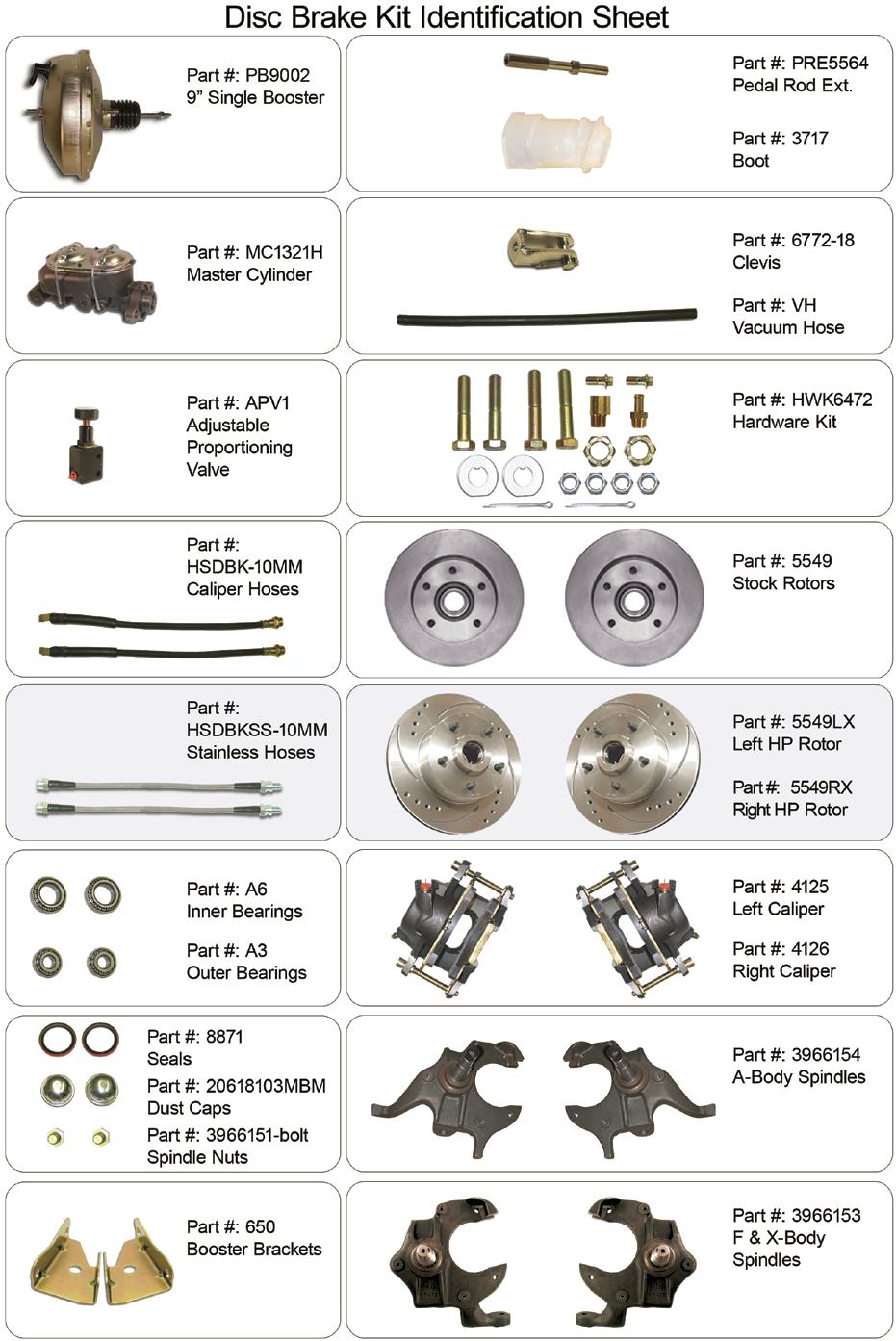
1 Installation Instructions for & A-Body 2 Drop Spindle Disc Brake Kit Instructions * High performance kit shown. Regular kit has plain rotors & hoses. WARNING Proper operation of your brakes is essential for your safety and the safety of others. Any brake service should be performed ONLY by persons experienced in the installation and proper operation of brake systems. It is the responsibility of the person installing any brake component or kit to determine the suitability of the component or kit for the particular application. After installation and before operating your vehicle, be sure to test the function of the brakes under controlled conditions. DO NOT DRIVE WITH UNTESTED BRAKES! IMPORTANT Take time to read all the literature that came with this kit. Check the provided list of parts against what you received to ensure all parts are present. While this kit was designed to make the process of changing brake parts as simple as possible. NOTE: WITH SOME KITS IT MAY BE NECESSARY TO MAKE MINOR CHANGES TO YOUR CAR! READ ALL WARRANTY DISCLAIMERS AND RETURN POLICIES INCLUDED IN THIS KIT PRIOR TO INSTALLATION! NOTE: Before operating the vehicle after installation, test the function of the brakes under controlled conditions. Make several stops in a safe area from low speed and gradually work up to normal speeds. DO NOT DRIVE WITH UNTESTED BRAKES! Always utilize safely restraints when operating the vehicle. The installation of disc brakes will require the use of 15 wheels. Any attempt to install disc brake with a 14 wheel will be the customer s responsibility.
2

3 Preparing your vehicle to install your brake system upgrade 1. Rack the vehicle. 2. If you don t have a rack, then you must take extra safety precautions. 3. Choose a firmly packed and level ground to jack up the vehicle. 4. Chock the rear wheels. 5. Jack the vehicle up and support it with jack stands and secure the pins. 6. Set the parking brake and put the transmission in park if automatic, reverse if manual transmission. 7. The front wheels should be allowed to free hang to relieve tension on the coil springs. Remember: NEVER rely on jacks to support a vehicle! Always test the steadiness of your stands that are supporting the vehicle before attempting to work on a raised vehicle! Preparing your parts 1. Locate the spindles and the inner wheel bearings. In order to install the inner bearings on new spindles, often you must remove.0004 from the inner bearing seating diameter. This can be accomplished with 240 grit emery paper and a rotary sanding motion on the spindle. Be sure to sand around the radius of the spindle which avoids flat spots. Continue this operation until the inner bearings can be slid onto the spindle without binding. Remember to use brake parts cleaner to keep all surfaces free of debris. Also use a lubricant such as bearing grease to ease them on. Do not grind or file on the spindle! 2. Pack all bearings with hi-temp wheel bearing grease. A bearing packing tool is ideal for the job. (See Figure 1) 3. Adhere the brake pads into place using disc brake quiet and bend outer brake tabs over calipers accordingly. Let them cure! 4. Mate up each threaded nut with its designated bolt or threaded surface. 5. Group your kit parts to speed up the installation. 6. Check your quantity of components versus the items list. Components to inspect, replace or upgrade prior to And / or during installation of disc conversion kits Figure 1 Universal Bearing Packer JEGS # 555-W1218 Tie rod ends and nuts Adjustment sleeves Control arm shafts, mounting bolts, & nuts Control Arms Idler arm and nut Pitman Arm and nut Upper Ball Joints and Lower Ball Joints and Shocks and hardware nuts nuts Residual valves Metering valves Proportioning valves Brake lines Stainless steel brake Stainless steel hardware lines
4 Suggestions: Take the time to identify any suspect parts that are not included in this kit. Consider making upgrades such as converting to polyurethane bushings, performance shocks, tubular a-arms, etc. Plan any Installation (s) of replacement parts during the various stages of the drum to disc conversion process. Installation of the disc brake kit will re quire the use of the following tools & chemicals: Most Tools Available at part numbers referenced below. Wheel bearing seal river Drum brake tool Flare wrench set Wheel chocks 3/8 ratchet drive set 555-W /8 Allen wrench or socket Jack stands Brake spring pliers 555-W175 Box end wrench set 555-W30630 Ball joint fork Tire iron / Brake bleeder wrench / Pliers 555-W30715 Screwdriver 555-W80007 Snips Grease gun 555-W54204 Universal Bearing Packer 555-W1218 Line bending tool Disc brake quiet Wheel bearing grease Ball pein hammer Disc brake pad spreader tool Brake Fluid Brake cleaner Caliper slide grease Hand cleaner Instructions Unless you have securely jacked up and supported the vehicle, do not proceed to install the kit! See section called Preparing your vehicle to install your brake system upgrade. At this point you can choose one of two methods Method 1. Remove the spindle with drums mounted as a unit, which is heavy, or Method 2. You can remove the components individually. Method 1. Removing the unit as one assembly 1. Remove the wheels. Mark them Left and Right so you will not effect any tire rotation that you have ongoing. Similarly if you have directional tires, place them accordingly. 2. Remove the steering arm/tie rods from the O.E. drum spindles. Disconnect / remove the tie rod ends from the drum-spindle setup. (Put the Tie rod nuts back on the tie rods so you don t lose or contaminate them.) (See Figure 2) 3. Disconnect the brake hoses at the frame and remove them. 4. Support the drum and spindle assembly so it won t fall on you by using a transmission jack, a body brace or similar device. 5. Remove the cotter pins from the upper and lower control arms nuts and break the spindle mounting nuts free. 6. With the ball joint nuts attached, use a ball joint separator tool to separate the joints from the spindles.


5 7. Remember that the coil springs are loaded, so you must relieve coil spring tension as you remove the upper ball joint nut. The safest option is to use a coil spring compressor so that the assembly can be removed in a controlled, safe Method. 8. Next remove the ball joint nuts and remove the assembly from its home between the control arms. 9. Put the ball joint nuts back on as you will need to reuse them. Method 2. Removing the component s individually 1. Remove the wheels. Mark them Left and Right so you will not effect any tire rotation that you have ongoing. Similarly if you have directional tires, place them accordingly. 2. Next remove the cotter pins and spindle nut. Set these aside as extras. 3. Crack open the bleeder screws on the front wheel cylinders to allow fluid to drain so the cylinders can retract slightly. 4. Remove the drum using the drum brake tool and or screwdriver. Remember, the drums will not pull off of the shoes if the wheel adjusters are not turned to allow the shoes to retract inward towards one another. 5. Remove the brake line or hose from the wheel cylinder to the frame mounts. 6. Remove the backing plate bolts so that the whole plate can be removed with cylinder, shoes and mounting hardware in tact. 7. Brace the lower control arm. 8. Remove the cotter pins from the upper and lower control arms nuts and break the spindle mounting nuts free. 9. With the ball joint nuts attached, use a ball joint separator tool (See Figure 2) to separate the joints from the spindles. 10. Remember that the coil springs are loaded, so you must relieve coil spring tension as you remove the upper ball joint nut. The safest option is to use a coil spring compressor (See Figure 3) so that the assembly can be removed in a controlled, safe method. 11. Next remove the ball joint nuts and remove the spindle from its home between the control arms. 12. Put the ball joint nuts back on as you will need to reuse them. Spindle Installation an d Disc Conversion Figure 2 Figure 3 Tie rod end / Ball joint Spring compressor separator (Different fork sizes) Various types available 1. Mount spindles to ball joints. Be mindful of LH and RH markings. Tighten the ball joint nuts, install washers and pins. 2. Fasten steering control arms and or tie rod ends. Conversion may require that the tie rod end be inserted above (stud & nut downward) the spindle for correct geometry and clearance. Grease the ball joints until grease runs out from the rubber.
 4. Next test fit your inner wheel bearing onto the spindle.")

6 Figure 4 3. Then tighten the steering control arms to the appropriate torque, install cotter pins, and check for smooth steering range of motion. Grease the tie rod ends until grease runs out from the rubber. (Remember that it is likely that an alignment will be needed.) 4. Next test fit your inner wheel bearing onto the spindle. (See preparing your parts) 5. Now it is time to prepare your rotor, install the inner wheel bearing and seal, and remember to discard the race provided with the bearing, as one is already pressed in for you. 6. Pack the bearings and the rotors with grease if this has yet to be done. 7. Press in the wheel seals using a block of wood or seal driver. 8. Install rotors and tighten down spindle nuts, add cages and install cotter pins. 9. Install grease caps after adding your final grease to the bearings. 10. Give the rotor a test spin and check for proper installation and true mounting. 11. Wash the protective film off of the rotors using brake parts cleaner. 12. Remove any packing material from the loaded calipers and remove the two 4-1/4 long bolts provided. Use disc brake quiet on the back of your brake pads if you have not done this already. (See preparing your parts) 13. Mount the caliper into the spindle cradle. You made Figure 5 need to move the two silver bolt sleeves in the calipers, to avoid contacting the spindle s housing. (Figure 5) Adjustment Sleeves


7 14. Grease the caliper slide pins and secure the mounting bolts to the appropriate torque. 15. Fasten brake hoses and be sure to put the copper washers on both sides of the banjo bolt fittings. 16. Using an assistant, turn the steering wheel lock to lock so you can see if there is any interference of steering components and flexible brake hoses. Bleeding order is rear passenger, rear driver, front passenger, front driver. Repeat. 17. Bleed the brakes, and when done use brake cleaner to make sure that the rotors are clean and ready for use. They should be chemical free. 18. Mount wheels and torque down lug nuts. 19. Remove the jack stands and slowly let down the vehicle and inspect for any clearance problems. 20. Using an assistant, turn the steering wheel lock to lock so you can see if there is any interference of steering components and flexible brake hoses. 21. Depress brake pedal and check for brake pressure and response. 22. Re-bleed if necessary. 23. Remember if you are upgrading to discs for the first time, you will need a residual pressure valve for the front, a residual pressure valve for the rear and a proportioning valve. See typical brake system configurations. Get a wheel alignment. Bleeders screws up! MASTER CYLINDER / POWER BOOSTER INSTALLATION 1. Disconnect the old master cylinder lines (Remember, if operating around painted surfaces, avoid brake fluid to paint contact). Remove any valves that are installed in the drum system and discard. If the vehicle has a pressure differential switch, it must also be removed. Remove the old master cylinder. 2. When changing from a manual brake system to a power system, the clevis assembly that attaches the push rod to the brake pedal must be removed and lowered one inch. If two holes are in the pedal use the lower hole for the power booster rod attachment. If only one hole exists from the manual system a second hole must be drilled one inch lower. Remove the clip and pin that attaches the clevis to the brake pedal and retain them. If the lower hole does not already exist, one must be drilled. Screw the clevis assembly onto the new push rod on the booster about 1/2. 3. Mount the booster to the fire-wall with the existing studs or bolts. Place the clevis assembly into the lower hole in the pedal and install the pin and clip.

8 4. Install the proper fitting into the intake manifold for vacuum. Connect the vacuum hose from the engine to the power booster. YOU WILL NEED AT LEAST 18 VACUUM TO OPERATE A BOOSTER. 5. Bench bleed the master cylinder with the supplied bleeder kit. 6. Install the master cylinder onto the booster. 7. Flush out the old brake fluid and replace with DOT Bleed the entire system starting at the wheel farthest from the master cylinder. Check the pedal feel for firmness. Adjust the clevis so there is 1/4 free play at the pedal stop. If pedal is spongy, bleed again. NOTE: If you are installing disc brakes without a power booster just mount the manual master to the fire-wall on the two studs that line up with the large hole. Attach the manual brake push rod to the pedal in the upper hole and adjust it so that it seats into the piston hole without applying pressure to the piston while at rest. Adjustable Proportioning Valve Adjustable proportioning valves are essentially pressure reducing valves and are often utilized in disc / drum, disc / disc and drum / drum braking systems. The valve is used to control front-to-rear brake pressure bias and will work for all types of vehicles. Install this valve between the distribution block and the rear flex hose in the front-to rear rigid brake line. Always use tube wrenches to tighten fittings properly. Final settings of this valve will depend on your particular vehicle, and individual preference. SPECIFICATIONS IN (Stamped on valve) Rigid brake line from the distribution block to this port. On early cars: the master cylinder rear port to this port. OUT (Stamped on valve) Rigid brake line to the rear flex hose. DECREASE Reduces the brake line pressure to the rear brakes. INCREASE Increases the pressure to the rear brakes. Maximum pressure regulation: 300 psi. Inlet port of valve: 1/8 27 NPT Standard adaptors: 3/8 24 for 3/16 line. Mounting hole diameter:.250 (two). WHAT TO DO IF YOU SUSPECT YOUR BOOSTER IS NOT WORKING It is rare that one of our kits will contain a defective power booster but if you suspect that your booster is not functioning correctly perform the following tests: BASIC TEST 1. With the engine off depress and release the brake pedal several times to eliminate vacuum from the power section. 2. Depress the pedal and hold down with light pressure, 15 to 25 pounds. 3. Start engine. 4. If the power unit is operating the pedal will drop slightly. Less pressure will be needed to hold the pedal down.

9 IF BOOSTER IS NOT OPERATING (GIVING A VERY HARD PEDAL) 1. Disconnect the vacuum hose from the booster check valve and check the vacuum level at this point with the engine running with a vacuum gauge. You should have at least 18 vacuum to the booster. Anything lower will begin to give a hard pedal. lf the vacuum level is below 18 you may be able to tune the engine and bring the vacuum level up to that level. If the vacuum level is around 16 the addition of a vacuum reserve canister will improve the braking. If the vacuum level is below 16 you will need to add an electric vacuum assist pump to supplement the engine vacuum. 2. If the vacuum level at the check valve is 18 check that the booster check valve is working. Disconnect the vacuum hose at the check valve and attach a piece of tubing. Blow into the valve. If air passes through the valve is defective and must be replaced. Also look into the hose attachment neck on the check valve and be sure there is no obstruction inside the valve. 3. Check your booster for a vacuum leak. With everything hooked up run the engine at moderate speed. Release the accelerator and turn the engine off. Wait 90 seconds and apply the brakes. If the brake applications are power assisted there is no leak. If there is no power assist the booster is defective and must be replaced. IF THE BOOSTER IS OPERATING BU T YOU STILL HAVE A HARD PEDAL 1. Your combination valve may have tripped shutting off fluid flow to the front or rear brakes. This condition will produce a very hard pedal. Check that fluid passes through the valve to both the front and rear by cracking a bleeder screw and observing a good flow of fluid. If one half of the system does hot have flow, re-center the valve. 2. You may have frozen rear wheel cylinders or frozen caliper pistons. If these components freeze you can get a very hard pedal. 3. Your pedal ratio may be too low. Check your pedal ratio. The pedal ratio must be in between 4:1 to 5:1. Some of the older cars that had power brakes used a ratio of almost 1:1. If you add a vacuum booster to this type of car you will have a very hard pedal. Typically we are talking about late 50 s cars. Adjust ratio as necessary. 4. Your booster may be undersized for the weight of the vehicle or the bore size of the master. If you try to use a small diameter booster such as a 7 street rod booster for a heavy car you will get a very hard pedal. Compounding the problem is an attempt to use a large bore master (1-1/4 or larger) on a small booster. IF YOUR BRAKE PEDAL IS VERY SENSITIVE AND THE BRAKES GRAB 1. Your pedal ratio may be too high. Power brakes will require a 4:1 to 5:1 ratio. If your ratio is around 6:1 you are getting too much mechanical advantage making the brakes extremely sensitive. Adjust the ratio to correct level. 2. The booster may be too large for the weight of the vehicle. Lightweight vehicles with large boosters give you touchy brakes. This effect may be dampened somewhat by going to a larger bore master. 3. Too large a booster for front drum brakes. Drum brakes do not require as much pressure as disc brakes (500 psi vs. 1,000 psi). If your booster is very large (11 ) and you have drum brakes you are over-boosted. Do a pressure test to determine what you have. 4. The booster has a cracked internal hub. When there is a crack in the phenolic hub inside the booster it will be either totally on or totally off. Any slight pressure to the pedal will cause the brakes to lock up. The booster must be replaced.
10 TEN REASON S FOR A POOR BRAKE PEDAL CAUSE REASON Bleeder screws on calipers not on top. A defective master cylinder which does not hold pressure. No residual pressure valve to rear drums. Hard line that loops up. Incorrect master cylinder. Incorrectly bled or adjusted rear calipers. Incorrect booster pin length. Silicone brake fluid. Rear wheel cylinders too large. Loose front wheel bearings. The bleeder screws on calipers must be at the 12:00 position on the caliper to allow all the air to escape during bleeding. A very common mistake installers will make is to reverse the side the caliper goes on giving you a situation where the caliper bleeder screw is facing down. It s also common to use the wrong caliper on a bolt on disc kit giving a situation where the bleeder hole is shifted from the 12:00 position producing a pocket of air at the top of the caliper bore which can not be dislodged. Check your bleeder hole orientation. If brake fluid bypasses a pressure seal on a master cylinder you will get a pedal that fades. To test for this obtain two inverted flare plugs at an auto parts store and plug both master cylinder outlets. Try your pedal. If the pedal is high and firm the master is good. If the pedal fades the master is bad. Replace master as necessary. Drum brakes require the use of a 10 Ib. residual pressure valve in the line. This residual pressure counter balances the drum brake spring tension keeping the shoes close to the drums. This results in a higher firmer pedal. You can test this by clamping off the rear hose removing the rear drums from the system. Now test your pedal. If the pedal gets better you will need to splice a 10 Ib. residual pressure valve into the rear line. Hard brake line that loops up and then back down will tend to trap air. It doesn t take much air to cause problems so check your lines carefully. If the bore size of the master cylinder is too small for the fluid requirements of the system you will get a very poor pedal. This will happen most frequently with four piston calipers and with four wheel disc brakes. The only solution for this is to install a larger bore master cylinder or a true four wheel disc master. Rear calipers that have an internal parking brake with a lever can be troublesome. These calipers must be adjusted so that the piston is moved out and the pads are close to the rotor. If this initial adjustment is not made the pistons will travel outward during activation but no squeezing of the rotor will occur. This can be checked by clamping off the rear hoses and checking if the pedal gets better. Adjust as necessary. The booster pin that pushes on the master cylinder must almost be touching the master cylinder piston face. A gap larger than 1/32 will begin to introduce a spongy pedal. Adjust as necessary. While silicone fluid is great because it does not attack paint it also aerates very easily and can give a spongy pedal. Rear drum wheel cylinders that are too large will give a poor pedal. Check as in step six above. Loose front wheel bearings will cause rotor wobble. This will cause the caliper pistons to retract too far into the caliper giving a spongy pedal every time you hit the brakes. Check and adjust as necessary.
11 UNIVERSAL FRONT DISC BRAKE CHECKLIST 1. Spindle properly secured to ball joints and tie rods with castle nut and cotter pin. 2. All mounting bolts properly tightened. 3. Wheel bearings properly packed with grease. 4. Inner bearing must be installed before grease seal. 5. Rotor I bearings slide onto spindle with ease. 6. Washer, castle nut properly torqued and cotter pin installed. 7. Calipers installed and properly torqued. 8. Spin rotor and check for any interference. (If any interference is found, resolve problem before driving vehicle.) 9. Flex lines are properly installed with no interference. 10. Power booster (if applicable) installed properly. 11. Master cylinder bench bled according to the instructions. 12. All brake lines are properly tightened and free of leaks. 13. Turn wheels lock to lock and check for any interference. 14. Place wheel onto vehicle and spin the wheel to make sure there is no interference between the brakes and wheel. UNIVERSAL REAR DISC BRAKE CHECKLIST 1. All bolts on base bracket properly tightened. 2. All caliper mounting bolts properly tightened. 3. Rotor slides onto axle with ease. 4. No interference with rotor and any other parts (splash shield, brackets, etc.). 5. Caliper is centered over the rotor (because of difference in axle lengths, you may have to shim caliper in or out). 6. No interference with caliper and rotor. 7. All brake lines are tight with no leaks. 8. Parking brake is properly adjusted and not dragging, with vehicle on ground. 9. Adjustable proportioning valve installed (if applicable). 10. Distribution block modification made (if applicable). 11. Brake system properly bled. WITH EVERY NEW SET OF ROTORS AND PADS, YOU SHOULD GIVE YOUR VEHICLE MILES OF EASY DRIVING TO PROPERLY SEAT THE PADS TO THE ROTORS. DO NOT TAKE THE VEHICLE UP TO 60 MPH AND JAM ON THE BRAKES BEFORE THE FIRST MILE BREAK IN PERIOD IS OVER, OR YOU WILL GLAZE THE PADS AND ROTORS.
DBK FULL-SIZE CHEVY DISC BRAKE conversion KIT
 DBK5964 1959-1964 FULL-SIZE CHEVY DISC BRAKE conversion KIT impala, bel air, biscayne Installation Instructions does not fit 14" rims must ust 15" or larger for this kit to be installed correctly on your
& GM A,F,& X Body Rear disc brake conversion kit
 630614 & 630615 GM A,F,& X Body Rear disc brake conversion kit FOR STAGGERED SHOCK APPLICATIONS HIGH PERFORMANCE KIT shown. regular kit includes plain rotors and rubber brake hoses. Note: Always refer
Installation Instructions
 Preparing your vehicle to install your brake system upgrade 1. Rack the vehicle. 2. If you don t have a rack, then you must take extra safety precautions. 3. Choose a firmly packed and level ground to
DBK9. Ford 9 rear end Disc Brake conversion kit. Installation Instructions
 DBK9 Ford 9 rear end Disc Brake conversion kit Fits the three most popular rear ends (3-3/8 x 2, 3-1/2 x 2-3/8, 3-9/16 x 2 ). Note: Also Available in High performance kit with stainless steel braided hoses
* High performance kit shown. Regular kit has plain rotors & hoses.
 Installation Instructions for 630200, 630210 & 630220 Fits 1962-72 Mopar B-Body, 1970-74 E-Body Disc Brake Conversion Kit * High performance kit shown. Regular kit has plain rotors & hoses. NOTE: ALWAYS
INSTALLATION INSTRUCTIONS
 INSTALLATION INSTRUCTIONS POWER FRONT DISC CONVERSION KIT A126-7 1963-66 CHEVY C10 PICKUP NON-POWER FRONT DISC CONVERSION KIT A126-8 1963-72 CHEVY C10 PICKUP Thank you for choosing STAINLESS STEEL BRAKES
1969 Camaro. Concourse Style Disc Brake Conversion Kit Instllation Instructions
 Concourse Style Disc Brake Conversion Kit Instllation Instructions 1969 Camaro (1970 Chevelle Kit Shown) This document contains our regular disc brake conversion instructions with the addition of GM assembly
A/F/X Body GM Installation Instructions Manual Disc Conversion
 A/F/X Body GM Installation Instructions Manual Disc Conversion 64-72 A Body / 67-69 F Body / 62-74 X Body DBMC09 & PVK71 pictured above (Booster, master & valve setups may vary by upgrades selected) Your
INSTALLATION INSTRUCTIONS
 INSTALLATION INSTRUCTIONS DISC BRAKE CONVERSION KITS A120-4 & A120-5 1964-1/2-66 Ford & Mercury Thank you for choosing STAINLESS STEEL BRAKES CORPORATION for your braking needs. Pleases take the time to
INSTALLATION INSTRUCTIONS
 INSTALLATION INSTRUCTIONS Disc Brake Spindle Kit SUM-BKA2447 1964-72 A-BODY 1967-69 F-BODY 1968-74 X-BODY Thank you for choosing SUMMIT RACING for your braking needs. Please take the time to read and carefully
A/F/X Body GM Installation Instructions Manual Disc Conversion
 A/F/X Body GM Installation Instructions Manual Disc Conversion 64-72 A Body / 67-69 F Body / 62-74 X Body DBMC09 & PVK71 pictured above (Booster, master & valve setups may vary by upgrades selected) Your
A/F/X Body GM Installation Instructions
 A/F/X Body GM Installation Instructions Power Disc Conversion 64-72 A Body / 67-69 F Body / 68-74 X Body 9 slimline booster pictured Your new disc brake conversion kit can be bolted up with standard hand
INSTALLATION INSTRUCTIONS
 INSTALLATION INSTRUCTIONS DISC BRAKE CONVERSION KITS A121-1, A121-2, A121-3, A121-4 1967-69 Ford & Mercury Thank you for choosing STAINLESS STEEL BRAKES CORPORATION for your braking needs. Pleases take
INSTALLATION INSTRUCTIONS
 INSTALLATION INSTRUCTIONS FRONT DISC BRAKE CONVERSION KIT A129-2 1959-64 Full Size Chevrolet Car and FRONT DISC BRAKE CONVERSION KITS A129-3 & A129-4 1965-68 Full Size Chevrolet Car Thank you for choosing
Installation Instructions
 Installation Instructions Rear Disc Brake Conversion Kit Item # RC4001, RC4001X Applications: Mopar 7.25, 8.25, 9.25 Axles Thank you for choosing Leed Brakes for your automotive product needs. Before you
Installation Instructions
 Installation Instructions Rear Disc Brake Conversion Kit Item # RC2001, RC2001X Applications: Mopar 8-3/4 & 9-3/4 Rear Axles Thank you for choosing Leed Brakes for your automotive product needs. Before
INSTALLATION INSTRUCTIONS
 INSTALLATION INSTRUCTIONS FRONT DISC BRAKE CONVERSION KITS: A132-1, A133, A133-1 A134, A134-1 1968-73 MUSTANG/FORD Thank you for choosing STAINLESS STEEL BRAKES CORPORATION for your braking needs. Please
55-64 Full Size Chevy
 55-64 Full Size Chevy Installation Instructions Power Disc Conversion 9 slimline booster pictured Your new disc brake conversion kit can be bolted up with standard hand tools. The only tools you may not
INSTALLATION INSTRUCTIONS
 INSTALLATION INSTRUCTIONS PERFORMANCE AT THE WHEELS KIT W120-22, W120-23 1964 1/2-69 MUSTANG Thank you for choosing STAINLESS STEEL BRAKES CORPORATION for your braking needs. Pleases take the time to read
INSTALLATION INSTRUCTIONS
 INSTALLATION INSTRUCTIONS DISC BRAKE CONVERSION KIT A120-20, A120-21 1964 1 /2-66 Ford & Mercury Thank you for choosing STAINLESS STEEL BRAKES CORPORATION for your braking needs. Pleases take the time
INSTALLATION INSTRUCTIONS
 INSTALLATION INSTRUCTIONS REAR DISC CONVERSION KIT A126-2 1988-98 C1500 2WD 10" REAR DRUM Thank you for choosing STAINLESS STEEL BRAKES CORPORATION for your braking needs. Pleases take the time to read
55-64 Full Size Chevy Installation Instructions Standard Disc Conversion
 55-64 Full Size Chevy Installation Instructions Standard Disc Conversion DBMC09, PV71 & PVB71 Pictured (Booster, master cylinder & valve setups may vary by upgrades selected) Your new disc brake conversion
INSTALLATION INSTRUCTIONS
 INSTALLATION INSTRUCTIONS REAR DISC BRAKE CONVERSION KIT A126-1 1973-87 CHEVROLET 1/2 TON 2WD Thank you for choosing STAINLESS STEEL BRAKES CORPORATION for your braking needs. Pleases take the time to
INSTALLATION INSTRUCTIONS
 INSTALLATION INSTRUCTIONS REAR DISC CONVERSION KIT A136-1 1976-86 AMC 20 AXLES WITH WARN FULL FLOATING AXLE CONVERSION Thank you for choosing STAINLESS STEEL BRAKES CORPORATION for your braking needs.
Installation Instructions
 Installation Instructions Rear Disc Brake Conversion Kit Item # RC1001, RC1001X Applications: 64-72 A-body, 67 F-Body, 63-67 X-body with Non Staggered Shocks Thank you for choosing GPS Auto for your automotive
INSTALLATION INSTRUCTIONS
 INSTALLATION INSTRUCTIONS REAR DISC BRAKE CONVERSION KIT A125-3 1965-72 GM A-BODY 10 & 12 BOLT AXLES Thank you for choosing STAINLESS STEEL BRAKES CORPORATION for your braking needs. Pleases take the time
INSTALLATION INSTRUCTIONS
 INSTALLATION INSTRUCTIONS REAR DISC BRAKE CONVERSION KIT A158 1994-97 Dodge Ram 1500 (2WD & 4WD) and REAR DISC BRAKE CONVERSION KIT A158-1 1998-01 Dodge Ram 1500 (2WD & 4WD) Thank you for choosing STAINLESS
INSTALLATION INSTRUCTIONS
 INSTALLATION INSTRUCTIONS PERFORMANCE AT THE WHEELS KITS W156-6 & W156-7 1965-74 MOPAR B & E BODY Thank you for choosing STAINLESS STEEL BRAKES CORPORATION for your braking needs. Pleases take the time
INSTALLATION INSTRUCTIONS
 INSTALLATION INSTRUCTIONS REAR DISC CONVERSION KIT A128-4 1997-2004 JEEP WRANGLER (TJ) WITH DANA 44 AXLES (non-abs) Thank you for choosing STAINLESS STEEL BRAKES for your braking needs. Pleases take the
INSTALLATION INSTRUCTIONS
 INSTALLATION INSTRUCTIONS REAR DISC BRAKE CONVERSION KIT A125-2 1955-70 FULL SIZE CHEVROLET Thank you for choosing STAINLESS STEEL BRAKES CORPORATION for your braking needs. Pleases take the time to read
INSTALLATION INSTRUCTIONS
 INSTALLATION INSTRUCTIONS BIG ROTOR / CALIPER RELOCATION REAR KIT SUM-BK1423 1999-2009 GM 1/2 Ton Trucks & SUVs Thank you for choosing SUMMIT RACING for your braking needs. Pleases take the time to read
ASSEMBLY INSTRUCTIONS FOR DYNALITE DRAG RACE FRONT HUB KIT WITH DIAMETER SOLID ROTOR PINTO / MUSTANG II
 ASSEMBLY INSTRUCTIONS FOR DYNALITE DRAG RACE FRONT HUB KIT WITH 0.75 DIAMETER SOLID ROTOR 97-978 PINTO / MUSTANG II (FIVE LUG CONFIGURATION ONLY)* PART NUMBER GROUP 0-03-B DISC BRAKES SHOULD ONLY BE INSTALLED
INSTALLATION INSTRUCTIONS
 INSTALLATION INSTRUCTIONS REAR DISC CONVERSION KIT A128 1990-1995 JEEP WRANGLER (YJ) WITH DANA 35 AXLES (non-abs) Thank you for choosing STAINLESS STEEL BRAKES CORPORATION for your braking needs. Pleases
INSTALLATION INSTRUCTIONS
 INSTALLATION INSTRUCTIONS BIG ROTOR / CALIPER RELOCATION FRONT KITS SUM-BK1422, BK1423, BK1424 1999-2006 GM 1/2 Ton Trucks & SUVs Thank you for choosing SUMMIT RACING for your braking needs. Pleases take
INSTALLATION INSTRUCTIONS
 INSTALLATION INSTRUCTIONS REAR CONVERSION KIT A111-2 (FORD 8" & 9" SMALL BEARING) & REAR CONVERSION KIT A111-3 (FORD 9 TORINO) Thank you for choosing STAINLESS STEEL BRAKES CORPORATION for your braking
INSTALLATION INSTRUCTIONS PERFORMANCE AT THE WHEELS KIT W125
 INSTALLATION INSTRUCTIONS PERFORMANCE AT THE WHEELS KIT W125 1968-81 CAMARO & FIREBIRD 10 & 12 BOLT W/"C" CLIPS Thank you for choosing STAINLESS STEEL BRAKES CORPORATION for your braking needs. Pleases
INSTALLATION INSTRUCTIONS
 INSTALLATION INSTRUCTIONS REAR DRUM TO DISC BRAKE CONVERSION KIT A118 pre-1985 Ford F150 (except 1983-1984 w/super H/D axle) Thank you for choosing STAINLESS STEEL BRAKES CORPORATION for your braking needs.
INSTALLATION INSTRUCTIONS
 INSTALLATION INSTRUCTIONS REAR DISC BRAKE CONVERSION KITS SUM-BK1329-X, SUM-BK1329-99904, SUM-BK1330-X, SUM-BK1330-99904 CHRYSLER 8 3 /4", 9 3 /4" and 2-PIECE REAR AXLES Thank you for choosing SUMMIT RACING
INSTALLATION INSTRUCTIONS
 INSTALLATION INSTRUCTIONS REAR DISC BRAKE CONVERSION KIT A126-3 1988-98 CHEVY K1500 4WD 10" DRUMS Thank you for choosing STAINLESS STEEL BRAKES CORPORATION for your braking needs. Pleases take the time
INSTALLATION INSTRUCTIONS
 INSTALLATION INSTRUCTIONS COMP. R AND COMP. S QUICK CHANGE KITS A200, A200-1 Thank you for choosing STAINLESS STEEL BRAKES CORPORATION for your braking needs. Pleases take the time to read and carefully
Mopar 8 3/4 & 9 3/4 (Dana) Installation Instructions Rear Disc Conversion
 Installation Instructions Rear Disc Conversion") Mopar 8 3/4 & 9 3/4 (Dana) Installation Instructions Rear Disc Conversion This kit is for either Mopar 8 ¾ or Mopar 9 ¾ (Dana). This kit is designed to work with axles with either GM 5 x 4.75 Bolt Pattern
Mopar 8 3/4 & 9 3/4 (Dana) Installation Instructions Rear Disc Conversion This kit is for either Mopar 8 ¾ or Mopar 9 ¾ (Dana). This kit is designed to work with axles with either GM 5 x 4.75 Bolt Pattern
INSTALLATION INSTRUCTIONS
 INSTALLATION INSTRUCTIONS INSTALLATION INSTRUCTIONS FOR A136 REAR DRUM TO DISC BRAKE CONVERSION KIT for 1970-75 Jeep, CJ SERIES with Dana 44 flanged axle Thank you for choosing STAINLESS STEEL BRAKES CORPORATION
INSTALLATION INSTRUCTIONS
 INSTALLATION INSTRUCTIONS REAR DISC CONVERSION KIT SUM-BK1414-X 1997-2004 JEEP WRANGLER (TJ) WITH DANA 44 AXLES (non-abs) Thank you for choosing SUMMIT RACING for your braking needs. Pleases take the time
INSTALLATION INSTRUCTIONS
 INSTALLATION INSTRUCTIONS REAR DISC BRAKE CONVERSION KIT A157 1991-2004 Dodge Dakota 2WD 1991-2002 Dodge Dakota 4WD 1998-2002 Dodge Durango Thank you for choosing STAINLESS STEEL BRAKES CORPORATION for
A /F/X Body Instruction Packet Rear Disc Conversion
 A /F/X Body Instruction Packet Rear Disc Conversion 64-72 A Body / 67-81 F Body / 62-74 X Body This kit is for axles with a 3 1/8 spread center to center on the top two bolt holes (pictured left). Rotor
A/F/X Body GM Installation Instructions Power Disc Conversion
 A/F/X Body GM Installation Instructions Power Disc Conversion 64-72 A Body / 67-69 F Body / 62-74 X Body DBMC09, PVK71 & RPB1001 pictured above (Booster, master & valve setups may vary by upgrades selected)
INSTALLATION INSTRUCTIONS
 INSTALLATION INSTRUCTIONS FRONT DISC BRAKE CONVERSION KITS SUM-BK1200, SUM-BK1201, SUM-BK1202, SUM-BK1203 1964-72 A-BODY 1967-69 F-BODY 1962-74 X-BODY (NOTE: 62-64 X-BODY REQUIRES 5-LUG STEERING ARMS)
60 76 A Body Mopar Power Disc Conversion Installation Instructions
 62-72 B & E BodyMopar 60 76 A Body Mopar Power Disc Conversion Installation Instructions Special A-Body only parts shown below (In addition to parts above for A-Body cars, part # MDC66DC & MDC46DC) Your
INSTALLATION INSTRUCTIONS
 INSTALLATION INSTRUCTIONS FRONT BIG BRAKE CONVERSION KIT A112-5 1987-93 FORD MUSTANG Thank you for choosing STAINLESS STEEL BRAKES CORPORATION for your braking needs. Pleases take the time to read and
DISC BRAKE/DUAL MASTER CYLINDER CONVERSION. Tools, Equipment and Supplies Needed:
 Please take the time to read the enclosed instructions carefully. If you have any questions, call our Product Assistance personnel for clarification. It is important to note that these instructions contain
INSTALLATION INSTRUCTIONS
 INSTALLATION INSTRUCTIONS REAR DRUM TO DISC BRAKE CONVERSION KIT A130 JEEP CJ SERIES W/AMC-20 REAR AXLES AND 5 x 5-1/2" BOLT CIRCLE Thank you for choosing STAINLESS STEEL BRAKES CORPORATION for your braking
Ford 8, 9 Small Bearing Installation Instructions Rear Disc Conversion
 Ford 8, 9 Small Bearing Installation Instructions Rear Disc Conversion This kit is for Ford 9 rear axles with the small (2.835 ) style bearing and Ford 8 rear ends. This kit is designed to work with axles
INSTALLATION INSTRUCTIONS
 INSTALLATION INSTRUCTIONS R1 REAR DRUM TO DISC BRAKE CONVERSION KIT A130-3 JEEP CJ SERIES W/AMC-20 REAR AXLES AND 5 x 5-1/2" BOLT CIRCLE Thank you for choosing STAINLESS STEEL BRAKES CORPORATION for your
55-64 Full Size GM (Impala, Bel Air, etc.) This kit is for axles with a 3 3/8 spread center to center on the top two bolt holes (pictured left).
 This kit is for axles with a 3 3/8 spread center to center on the top two bolt holes (pictured left).") SUM-BK1624A Full Size GM Installation Instructions Rear Disc Conversion 55-64 Full Size GM (Impala, Bel Air, etc.) This kit is for axles with a 3 3/8 spread center to center on the top two bolt holes (pictured
SUM-BK1624A Full Size GM Installation Instructions Rear Disc Conversion 55-64 Full Size GM (Impala, Bel Air, etc.) This kit is for axles with a 3 3/8 spread center to center on the top two bolt holes (pictured
INSTALLATION INSTRUCTIONS
 INSTALLATION INSTRUCTIONS FRONT DISC BRAKE CONVERSION KITS A148-9 & A148-15 1949-54 Chevy Trucks Thank you for choosing STAINLESS STEEL BRAKES CORPORATION for your braking needs. Please take the time to
INSTALLATION INSTRUCTIONS
 INSTALLATION INSTRUCTIONS PERFORMANCE AT THE WHEELS KIT W155-5 CHRYSLER 8 3 /4" & 9 3 /4" REAR AXLES Thank you for choosing STAINLESS STEEL BRAKES CORPORATION for your braking needs. Please take the time
Signature Series A/F/X Body GM Installation Instructions Power Disc Conversion
 Signature Series A/F/X Body GM Installation Instructions Power Disc Conversion 64-72 A Body / 67-69 F Body / 62-74 X Body Your new disc brake conversion kit can be bolted up with standard hand tools. The
ASSEMBLY INSTRUCTIONS
 ASSEMBLY INSTRUCTIONS FOR DYNALITE PRO SERIES FRONT HUB KIT WITH.75 DIAMETER VENTED ROTOR 970-973 FORD MUSTANG (DRUM / DISC SPINDLE) PART NUMBER GROUP 0-905 WARNING INSTALLATION OF THIS KIT SHOULD ONLY
INSTALLATION INSTRUCTIONS
 INSTALLATION INSTRUCTIONS REAR DISC BRAKE CONVERSION KITS A112, A112-1 & A112-93 1979-93 FORD MUSTANG with 7.5" & 8.8" AXLES Thank you for choosing STAINLESS STEEL BRAKES CORPORATION for your braking needs.
ASSEMBLY INSTRUCTIONS
 ASSEMBLY INSTRUCTIONS FOR DYNALITE PRO SERIES REAR PARKING BRAKE KIT VENTED ROTOR TYPE (.8 OFFSET) BOLT CHEVY PART NUMBER GROUP 0-7 INSTALLATION OF THIS KIT SHOULD ONLY BE PERFORMED BY PERSONS EXPERIENCED
INSTALLATION INSTRUCTIONS R1 REAR CONVERSION KIT
 INSTALLATION INSTRUCTIONS R1 REAR CONVERSION KIT INSTRUCTION FOR ASSEMBLY OF JEEP CJ SERIES W/AMC 20 REAR AXLES, 5 x 5-1/2" BOLT CIRCLE WITH A130-4 FULL FLOATING AXLE OR A130-5 (1 PIECE AXLE) Thank you
ASSEMBLY INSTRUCTIONS
 ASSEMBLY INSTRUCTIONS FOR DYNALITE PRO SERIES REAR PARKING BRAKE KIT VENTED ROTOR TYPE (.36 OFFSET) MOPAR 8-3/ / DANA 60 FOR USE W/GREEN () NON-ADJUSTABLE BEARINGS W/SNAP RING PART NUMBER 0-7* WARNING
ASSEMBLY INSTRUCTIONS
 ASSEMBLY INSTRUCTIONS FOR DYNALITE PRO SERIES REAR PARKING BRAKE KIT WITH.9 DIAMETER VENTED ROTOR (.36 OFFSET) BIG BEARING FORD PART NUMBER GROUP 0-739 INSTALLATION OF THIS KIT SHOULD ONLY BE PERFORMED
ASSEMBLY INSTRUCTIONS
 ASSEMBLY INSTRUCTIONS FOR FORGED SUPERLITE BIG BRAKE FRONT HUB KIT WITH 3.00 DIAMETER VENTED ROTOR 968-969 FORD MUSTANG (DISC BRAKE SPINDLE ONLY) PART NUMBER GROUP 0-950 WARNING INSTALLATION OF THIS KIT
INSTALLATION INSTRUCTIONS
 INSTALLATION INSTRUCTIONS PERFORMANCE AT THE WHEELS KIT W125-42 GM 10 & 12 Bolt Rear Axles with Staggered or non-staggered Shocks with C-Clips Thank you for choosing STAINLESS STEEL BRAKES CORPORATION
INSTALLATION INSTRUCTIONS
 INSTALLATION INSTRUCTIONS FX4 ELITE REAR DISC CONVERSION KITS WITH INTERNAL PARKING BRAKE A110-14, A111-25, A111-29 for FORD 8" & 9" REAR ENDS Thank you for choosing STAINLESS STEEL BRAKES CORPORATION
INSTALLATION INSTRUCTIONS
 INSTALLATION INSTRUCTIONS INSTRUCTION FOR ASSEMBLY OF JEEP CJ SERIES W/AMC 20 REAR AXLES, 5 x 5-1/2" BOLT CIRCLE WITH A130-1 FULL FLOATING AXLE OR A130-2 (1 PIECE AXLE) Thank you for choosing STAINLESS
ASSEMBLY INSTRUCTIONS
 ASSEMBLY INSTRUCTIONS FOR DYNALITE PRO SERIES REAR PARKING BRAKE KIT VENTED ROTOR TYPE (.50 OFFSET) BIG BEARING FORD, NEW STYLE PART NUMBER 0-70* WARNING INSTALLATION OF THIS KIT SHOULD ONLY BE PERFORMED
INSTALLATION INSTRUCTIONS
 INSTALLATION INSTRUCTIONS REAR CONVERSION KITS SUM-BK1326-X, SUM-BK1326-99904, SUM-BK1327-X, SUM-BK1327-99904, SUM-BK1328-X, SUM-BK1328-99904 FORD 8 and 9 AXLES WITH GM & FORD BOLT PATTERN Thank you for
ASSEMBLY INSTRUCTIONS
 ASSEMBLY INSTRUCTIONS FOR DYNALITE PRO SERIES REAR PARKING BRAKE KIT WITH.9 DIAMETER VENTED ROTOR (. OFFSET) 005 - PRESENT MUSTANG 8.8 (5 LUG) PART NUMBER GROUP 0-98 INSTALLATION OF THIS KIT SHOULD ONLY
INSTALLATION INSTRUCTIONS
 INSTALLATION INSTRUCTIONS FORCE 10 SPORT R1 REAR DISC CONVERSION KIT A126-50 2005-10 Chevrolet Silverado and GMC Sierra Thank you for choosing STAINLESS STEEL BRAKES CORPORATION for your braking needs.
INSTALLATION INSTRUCTIONS
 INSTALLATION INSTRUCTIONS REAR DISC BRAKE CONVERSION KIT A117-1, A117-2 1991-97 S10 PICKUP & BLAZER 1985-02 ASTRO AND SAFARI VAN Thank you for choosing STAINLESS STEEL BRAKES CORPORATION for your braking
Tools, Equipment and Supplies Needed:
 153-162 DISC BRAKE/DUAL MASTER CYLINDER CONVERSION Please take the time to read the enclosed instructions carefully. If you have any questions, call our Product Assistance personnel for clarifi cation.
ASSEMBLY INSTRUCTIONS
 ASSEMBLY INSTRUCTIONS FOR DYNALITE PRO SERIES REAR PARKING BRAKE KIT VENTED ROTOR TYPE (.8 OFFSET) BOLT CHEVY PART NUMBER 0-7* WARNING INSTALLATION OF THIS KIT SHOULD ONLY BE PERFORMED BY PERSONS EXPERIENCED
ASSEMBLY INSTRUCTIONS FOR DYNALITE PRO SERIES FRONT HUB KIT WITH DIAMETER VENTED ROTOR EARLY FORD - DRUM SPINDLE
 ASSEMBLY INSTRUCTIONS FOR DYNALITE PRO SERIES FRONT HUB KIT WITH.00 DIAMETER VENTED ROTOR 93-98 EARLY FORD - DRUM SPINDLE PART NUMBER GROUP -3 DISC BRAKES SHOULD ONLY BE INSTALLED BY SOMEONE EXPERIENCED
ASSEMBLY INSTRUCTIONS FOR PART NUMBER GROUP
 ASSEMBLY INSTRUCTIONS FOR DYNAPRO 6 BIG BRAKE FRONT HAT KIT, 1.19 DIAMETER VENTED ROTOR 1990-005 ACURA/CIVIC ( LUG) 000-003 CIVIC SI ( LUG) 007 - PRESENT HONDA FIT FOR FACTORY 6 mm DISC SPINDLE PART NUMBER
ASSEMBLY INSTRUCTIONS FOR DYNALITE PRO SERIES REAR PARKING BRAKE KIT WITH DIAMETER SOLID ROTOR (2.81 OFFSET) OLDS / PONTIAC
 OLDS / PONTIAC") ASSEMBLY INSTRUCTIONS FOR DYNALITE PRO SERIES REAR PARKING BRAKE KIT WITH.9 DIAMETER SOLID ROTOR (.8 OFFSET) OLDS / PONTIAC PART NUMBER GROUP 0-6703 DISC BRAKES SHOULD ONLY BE INSTALLED BY SOMEONE EXPERIENCED
ASSEMBLY INSTRUCTIONS FOR DYNALITE PRO SERIES REAR PARKING BRAKE KIT WITH.9 DIAMETER SOLID ROTOR (.8 OFFSET) OLDS / PONTIAC PART NUMBER GROUP 0-6703 DISC BRAKES SHOULD ONLY BE INSTALLED BY SOMEONE EXPERIENCED
NEW BRAKE INSTALLATION. Let us show you how a
 Tech Article From Newsletter 17.2-2nd Quarter of 2011 NEW BRAKE INSTALLATION Let us show you how a Big Brake Install is easier than you think!! So, you have a 572 (or a hot 383) in your shoebox... you
ASSEMBLY INSTRUCTIONS FOR WILWOOD FRONT D8-6 CALIPER, BRAKE PAD, AND FLEX LINE REPLACEMENT KIT CHEVROLET CORVETTE
 ASSEMBLY INSTRUCTIONS FOR WILWOOD FRONT D8-6 CALIPER, BRAKE PAD, AND FLEX LINE REPLACEMENT KIT 965-98 CHEVROLET CORVETTE PART NUMBER GROUP 40-857 DISC BRAKES SHOULD ONLY BE INSTALLED BY SOMEONE EXPERIENCED
EGR Performance Brakes Assembly Instructions DODGE DANA 70 '87 - '93 (Will not fit stock sized dual rear wheels)
") EGR Performance Brakes Assembly Instructions DODGE DANA 70 '87 - '93 (Will not fit stock sized dual rear wheels) Got Brakes? Parts List (2) Vented Rotors (2) Multi hole Cable Mount & L Brkt (2) Axle Tube
EGR Performance Brakes Assembly Instructions DODGE DANA 70 '87 - '93 (Will not fit stock sized dual rear wheels) Got Brakes? Parts List (2) Vented Rotors (2) Multi hole Cable Mount & L Brkt (2) Axle Tube
REMOVAL & INSTALLATION
 REMOVAL & INSTALLATION FRONT DISC BRAKE PADS 1. Raise and support front of vehicle. Remove wheels. Remove caliper bolt and brakeline bracket bolts. Pivot caliper aside. Remove pads and pad shim. Remove
ASSEMBLY INSTRUCTIONS FOR DYNALITE PRO SERIES REAR PARKING BRAKE KIT WITH DIAMETER VENTED ROTOR (2.36 OFFSET) BIG BEARING FORD
 BIG BEARING FORD") ASSEMBLY INSTRUCTIONS FOR DYNALITE PRO SERIES REAR PARKING BRAKE KIT WITH 1.19 DIAMETER VENTED ROTOR (.36 OFFSET) BIG BEARING FORD PART NUMBER GROUP 10-7139 DISC BRAKES SHOULD ONLY BE INSTALLED BY SOMEONE
ASSEMBLY INSTRUCTIONS FOR DYNALITE PRO SERIES REAR PARKING BRAKE KIT WITH 1.19 DIAMETER VENTED ROTOR (.36 OFFSET) BIG BEARING FORD PART NUMBER GROUP 10-7139 DISC BRAKES SHOULD ONLY BE INSTALLED BY SOMEONE
BRAKE SYSTEM Nissan 240SX DESCRIPTION BRAKE BLEEDING * PLEASE READ FIRST * BLEEDING PROCEDURES ADJUSTMENTS BRAKE PEDAL HEIGHT SPECS TABLE
 BRAKE SYSTEM 1990 Nissan 240SX 1990 BRAKE SYSTEMS Nissan Disc & Drum Axxess, Maxima, Pathfinder, Pickup, Pulsar NX, Sentra, Stanza, 240SX, 300ZX DESCRIPTION All brake systems are hydraulically operated
ASSEMBLY INSTRUCTIONS
 ASSEMBLY INSTRUCTIONS FOR DYNALITE PRO SERIES FRONT HUB KIT WITH.75 DIAMETER VENTED ROTOR 1980-1987 GENERAL MOTORS G BODY DISC SPINDLE PART NUMBER GROUP -508-B WARNING INSTALLATION OF THIS KIT SHOULD ONLY
APPLIED GMC / 1 (800) KATO RD. FREMONT, CA GMC ALL DISC BRAKE KIT
 KATO RD. FREMONT, CA GMC ALL DISC BRAKE KIT") APPLIED GMC 510-440-1101 / 1 (800) 752-7502 47626 KATO RD. FREMONT, CA 94538 GMC ALL DISC BRAKE KIT Shade Tree Mechanic's Guide to Disc Brake Upgrade Installation Instructions Written by: Edited by: Randy
APPLIED GMC 510-440-1101 / 1 (800) 752-7502 47626 KATO RD. FREMONT, CA 94538 GMC ALL DISC BRAKE KIT Shade Tree Mechanic's Guide to Disc Brake Upgrade Installation Instructions Written by: Edited by: Randy
ASSEMBLY INSTRUCTIONS FOR DYNAPRO BIG BRAKE FRONT HAT KIT, WITH DIAMETER VENTED ROTOR - RACE
 www.wilwood.com ASSEMBLY INSTRUCTIONS FOR DYNAPRO BIG BRAKE FRONT HAT KIT, WITH 11.75 DIAMETER VENTED ROTOR - RACE 00 - PRESENT BMW MINI COOPER AND MINI COOPER S PART NUMBER GROUP 10-870 DISC BRAKES SHOULD
BIG BRAKE KIT FOR TJ, ZJ, XJ D44 & D30
 BIG BRAKE KIT FOR TJ, ZJ, XJ D44 & D30 16 KIT PART NUMBER 41002010AA 17 KIT PART NUMBER 41002015AA Installation Guide (Updated 12/01/09) Page 1 of 11 PLEASE READ BEFORE YOU START IN ORDER TO INSTALL THIS
ASSEMBLY INSTRUCTIONS FOR
 ASSEMBLY INSTRUCTIONS FOR DYNALITE PRO SERIES REAR AXLE KIT WITH.9 DIAMETER VENTED ROTOR (.36 OFFSET) MOPAR 8-3/ DANA 60 FOR USE WITH GREEN* NON-ADJUSTABLE BEARING PART NUMBER GROUP 0-7-B DISC BRAKES SHOULD
ASSEMBLY INSTRUCTIONS FOR DYNALITE BIG BRAKE FRONT HUB KIT WITH DIAMETER VENTED ROTOR CAMARO/FIREBIRD (DISC SPINDLE)
") ASSEMBLY INSTRUCTIONS FOR DYNALITE BIG BRAKE FRONT HUB KIT WITH.75 DIAMETER VENTED ROTOR 1979-1981 CAMARO/FIREBIRD (DISC SPINDLE) PART NUMBER GROUP -817-B DISC BRAKES SHOULD ONLY BE INSTALLED BY SOMEONE
ASSEMBLY INSTRUCTIONS FOR DYNALITE BIG BRAKE FRONT HUB KIT WITH.75 DIAMETER VENTED ROTOR 1979-1981 CAMARO/FIREBIRD (DISC SPINDLE) PART NUMBER GROUP -817-B DISC BRAKES SHOULD ONLY BE INSTALLED BY SOMEONE
Installation Notes: #86000-R Race Series +3.5 L/T Kit
 159 North Maple St. Unit J, CORONA CA 92880 P. 951-737-9682 F. 951-737-9006 WWW.CHAOSFAB.COM Installation Notes: #86000-R Race Series +3.5 L/T Kit Factory manual is recommended for removal and re-installation
ASSEMBLY INSTRUCTIONS FOR SUPERLITE 6R PRO SERIES FRONT HUB KIT WITH DIAMETER VENTED ROTOR GENERAL MOTORS G BODY DISC SPINDLE
 ASSEMBLY INSTRUCTIONS FOR SUPERLITE 6R PRO SERIES FRONT HUB KIT WITH 1.88 DIAMETER VENTED ROTOR 1980-1987 GENERAL MOTORS G BODY DISC SPINDLE PART NUMBER GROUP 10-198 DISC BRAKES SHOULD ONLY BE INSTALLED
INSTALLATION INSTRUCTIONS
 INSTALLATION INSTRUCTIONS COMP CALIPER QUICK CHANGE KIT A213 1968-73 MUSTANG Thank you for choosing STAINLESS STEEL BRAKES CORPORATION for your braking needs. Pleases take the time to read and carefully
ASSEMBLY INSTRUCTIONS FOR WILWOOD D154 PRO SERIES REAR PARKING BRAKE KIT WITH DIAMETER VENTED ROTOR (2.42 OFFSET) C-10 CHEVY, 5 LUG
 C-10 CHEVY, 5 LUG") ASSEMBLY INSTRUCTIONS FOR WILWOOD D154 PRO SERIES REAR PARKING BRAKE KIT WITH 1.19 METER VENTED ROTOR (.4 OFFSET) 1963-1987 C-10 CHEVY, 5 LUG PART NUMBER GROUP 140-1569 DISC BRAKES SHOULD ONLY BE INSTALLED
ASSEMBLY INSTRUCTIONS FOR WILWOOD D154 PRO SERIES REAR PARKING BRAKE KIT WITH 1.19 METER VENTED ROTOR (.4 OFFSET) 1963-1987 C-10 CHEVY, 5 LUG PART NUMBER GROUP 140-1569 DISC BRAKES SHOULD ONLY BE INSTALLED
Brake System Diagnosis and Service
 AUMT 1310 - Brake System Diagnosis and Brake System Inspection Brake System Diagnosis and Donald Jones Brookhaven College Road test Hydraulic system Leaks Fluid condition Disc brakes Rotors and pads Drum
ASSEMBLY INSTRUCTIONS FOR DYNALITE PRO SERIES REAR PARKING BRAKE KIT WITH DIAMETER VENTED ROTOR (2.75 OFFSET) CAMARO / FIREBIRD
 CAMARO / FIREBIRD") ASSEMBLY INSTRUCTIONS FOR DYNALITE PRO SERIES REAR PARKING BRAKE KIT WITH.9 DIAMETER VENTED ROTOR (.75 OFFSET) 993-997 CAMARO / FIREBIRD PART NUMBER GROUP 0-78 DISC BRAKES SHOULD ONLY BE INSTALLED BY SOMEONE
ASSEMBLY INSTRUCTIONS FOR DYNALITE PRO SERIES REAR PARKING BRAKE KIT WITH.9 DIAMETER VENTED ROTOR (.75 OFFSET) 993-997 CAMARO / FIREBIRD PART NUMBER GROUP 0-78 DISC BRAKES SHOULD ONLY BE INSTALLED BY SOMEONE
DISC BRAKES SHOULD ONLY BE INSTALLED BY SOMEONE EXPERIENCED AND COMPETENT IN THE INSTALLATION AND MAINTENANCE OF DISC BRAKES READ ALL WARNINGS
 ASSEMBLY INSTRUCTIONS FOR SUPERLITE BIG BRAKE FRONT HUB KIT WITH 1.90 DIAMETER VENTED ROTOR 197-199 CAMARO, DISC/DRUM SPINDLE 197-197 NOVA, DISC/DRUM SPINDLE 19-19 CHEVY II, DRUM SPINDLE WITH MODIFICATIONS
BRAKE SYSTEM Article Text 1992 Mitsubishi Mirage For a a a a a Copyright 1998 Mitchell Repair Information Company, LLC Monday, April 01, :05AM
 Article Text ARTICLE BEGINNING 1992 BRAKES Chrysler Motors/Mitsubishi - Disc & Drum Chrysler Motors: Colt, Colt 200, Colt Vista, Ram-50, Stealth, Summit, Summit Wagon; Mitsubishi: Diamante, Eclipse, Expo/Expo
ASSEMBLY INSTRUCTIONS FOR PRO-MATRIX OE UPGRADE PAD AND ROTOR KIT REAR, WITH DIAMETER VENTED ROTOR CHEVROLET C-4 CORVETTE
 ASSEMBLY INSTRUCTIONS FOR PRO-MATRIX OE UPGRADE PAD AND ROTOR KIT REAR, WITH 1.00 DIAMETER VENTED ROTOR 1988-1996 CHEVROLET C-4 CORVETTE PART NUMBER GROUP 140-8314 DISC BRAKES SHOULD ONLY BE INSTALLED
FORD FAIRLANE Booster Conversion Kit ( TORINO, RANCHERO )
") 1966-1971 FORD FAIRLANE Booster Conversion Kit ( TORINO, RANCHERO ) F R Unboxing your kit: 1. Remove new booster, bracket assembly and master cylinder from their boxes and inspect the parts. 2. New boosters
1966-1971 FORD FAIRLANE Booster Conversion Kit ( TORINO, RANCHERO ) F R Unboxing your kit: 1. Remove new booster, bracket assembly and master cylinder from their boxes and inspect the parts. 2. New boosters
82-92 CAMARO, FIREBIRD/78-87 REGAL, MONTE CARLO, GRAND PRIX/ S-10 RACE/STREET 4-PISTON FRONT BRAKE KIT INSTRUCTIONS
 82-92 CAMARO, FIREBIRD/78-87 REGAL, MONTE CARLO, GRAND PRIX/ S-10 RACE/STREET 4-PISTON FRONT BRAKE KIT INSTRUCTIONS 1 AEROSPACE COMPONENTS 727.347.9915 82-92 CAMARO/78-87 REGAL YOU WILL NEED TO MODIFY