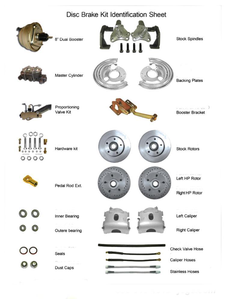
* High performance kit shown. Regular kit has plain rotors & hoses.
|
|
|
- Abraham Davidson
- 6 years ago
- Views:
Transcription

1 Installation Instructions for , & Fits Mopar B-Body, E-Body Disc Brake Conversion Kit * High performance kit shown. Regular kit has plain rotors & hoses. NOTE: ALWAYS REFER TO THE VEHICLE OWNER S MANUAL FOR CORRECT TORQUE SPECIFICATIONS WHEN INSTALLING KIT.
2 Page 1 Warning Proper operation of your brakes is essential for your safety and the safety of others. Any brake service should be performed ONLY by persons experienced in the installation and proper operation of brake systems. It is the responsibility of the person installing any brake component or kit to determine the suitability of the component or kit for the particular application. After installation, and before operating your vehicle, be sure to test the function of the brakes under controlled conditions. DO NOT DRIVE WITH UNTESTED BRAKES! Important Take time to read all the literature that came with this kit. Before beginning installation check the provided list of parts against what you received to ensure that all parts are present. While this kit was designed to make the process of changing brake parts as simple as possible, NOTE: With some kits it may be necessary to make minor changes to your car! Read all warranty disclaimers and return policies included in this kit prior to installation! Notes Always utilize safely restraints when operating the vehicle. The installation of disc brakes will require the use of 15 wheels. Any attempt to install disc brake with a 14 wheel will be the customer s responsibility. This kit is an aftermarket solution. It is not intended to be a direct installation or OEM replacement. Due to changes in production in certain years, your car may require modifications beyond these instructions for this kit to install properly.
3 Page 2
4 Page 3 PREPARING YOUR VEHICLE TO INSTALL YOUR BRAKE SYSTEM UPGRADE 1. Rack the vehicle. 2. If you don t have a rack, then you must take extra safety precautions. 3. Choose a firmly packed and level ground to jack up the vehicle. 4. Chock the rear wheels. 5. Jack the vehicle up and support it with jack stands and secure the pins. 6. Set the parking brake and put the transmission in park if automatic, reverse if manual transmission. 7. The front wheels should be allowed to free hang to relieve tension on the coil springs. PREPARING YOUR PARTS IMPORTANT NEVER rely on jacks to support a vehicle! Always test the steadiness of your stands that are supporting the vehicle before attempting to work on a raised vehicle! 1. Locate the spindles and the inner wheel bearings. In order to install the inner bearings on new spindles, often you must remove.0004 from the inner bearing seating diameter. This can be accomplished with 240 grit emery paper and a rotary sanding motion on the spindle. Be sure to sand around the radius of the spindle which avoids flat spots. Continue this operation until the inner bearings can be slid onto the spindle without binding. Remember to use brake parts cleaner to keep all surfaces free of debris. Also use a lubricant such as bearing grease to ease them on. Do not grind or file on the spindle! 2. Pack all bearings with hi-temp wheel bearing grease. A bearing packing tool is ideal for the job. 3. Adhere the brake pads into place using disc brake quiet and bend outer brake tabs over calipers accordingly. Let them cure! 4. Mate up each threaded nut with its designated bolt or threaded surface. 5. Group your kit parts to speed up the installation. 6. Check your quantity of components versus the items list. COMPONENTS TO INSPECT, REPLACE OR UPGRADE DURING INSTALLATION OF DISC CONVERSION KITS Tie rod ends and nuts Adjustment sleeves Control arm shafts, mounting bolts, & nuts Control Arms Idler arm and nut Pitman Arm and nut Upper Ball Joints and nuts Lower Ball Joints and nuts Shocks and hardware Residual valves Metering valves Proportioning valves Brake lines Stainless steel brake lines Stainless steel hardware SUGGESTIONS Take the time to identify any suspect parts that are not included in this kit. Consider making upgrades such as converting to polyurethane bushings, performance shocks, tubular a-arms, etc. Plan any Installation (s) of replacement parts during the various stages of the drum to disc conversion process.
5 Page 4 INSTALLATION OF THE DISC BRAKE KIT REQUIRES THE USE OF THE FOLLOWING TOOLS & CHEMICALS: Wheel bearing seal driver Drum brake tool Flare wrench set Wheel chocks 3/8 ratchet drive set 3/8 Allen wrench or socket Jack stands Brake spring pliers Box end wrench set Ball joint fork Tire iron Brake bleeder wrench Pliers Screwdriver Snips Grease gun Universal Bearing Packer Line bending tool Disc brake quiet Wheel bearing grease Ball pein hammer Disc brake pad spreader Brake Fluid Brake cleaner tool Caliper slide grease Hand cleaner INSTRUCTIONS Unless you have securely jacked up and supported the vehicle, do not proceed to install the kit! See section called Preparing your vehicle to install your brake system upgrade. 1. If you are performing the installation with a jack be sure that the parking brake is set and that the rear wheels are chocked. Support the front of the vehicle with jack stands. Never work on sloping ground. 2. If you re using a lift, raise the vehicle to a comfortable working height. 3. Remove the front wheels. 4. At this point, be sure to place the proper support under the lower control arm. Failure to do so will allow the coil spring to blow out when the spindle is removed which could result in serious Injury and damage to the vehicle. 5. Utilizing a mallet and screwdriver, remove the brake hose clip at the frame bracket by tapping it loose. Disconnect the brake hose from the hard line using the appropriate flare wrenches. 6. Locate the ball joint at the tie rod end and the steering arm. Remove the cotter pin and loosen the ball Joint nut approximately 1/2 off. This allows for a controlled, separation of the tie rod end and the steering arm. Place the balk joint fork between the steering arm and the ball joint. Strike the fork with a mallet until the steering arm and ball Joint separate. Remove the ball joint nut. 7. Repeat the process described in step 6 for the lower and upper ball joint at the spindle. Place the ball joint fork between the spindle and the ball joint. 8. Slowly lower the support and remove the drum brake assembly as a unit. 9. Inspect the ball joints for signs off excessive wear and check to see if the rubber boot Is torn. If the ball Joint wobbles excessively or is worn, now is the time for replacement. Clean the ball joints with a rag. Keep the lower ball joint and steering arm assembly because it will be reused in this installation. 10. Take the drum brake assembly to a bench to disassemble it. Remove the dust cover by twisting a screwdriver between the dust cover and the hub. Remove the cotter pin and take off the spindle nut. Save the spindle nut and the keyed washer to use on the disc spindle. Remove the bolts that hold the steering arm to the spindle and retain the arm and the bolts to use on the disc spindle. (This requires removing the brake shoes which is easier with a drum brake tool.)


6 Page Bolt the old steering arm ball joint assembly to the new disc brake spindle as shown below. Passenger Side Spindle Bolts Front of Car 12. Now assemble the caliper bracket to the spindle with the 1 1/2 bolts supplied with the spindles. Passenger Side Front of Car

7 Page Now install the inner bearing (the larger bearing) and bearing seal into the rotor as shown 13. below. Carefully tap the bearing seal into place securely with a small hammer or large socket. Be sure to grease the bearings before installing. Tech Advisory: 60 s used left hand thread wheel studs on the driver side, change studs if necessary 14. Install the rotor onto the spindle followed by the outer bearing. Re-use the old spindle nuts and washers. Tighten the spindle nut until the rotor does not spin freely and then back off the nut slightly until the rotor spins freely but does not wobble. Secure with cotter pin. Install the dust cap. 15. After the spindle is on the rotor place the inboard disc pad into the caliper cradle. Grease the caliper slides. Now drop the caliper onto the cradle with the outboard pad on the other side of the rotor so the pads sandwich the rotor between them. (See detailed Single Piston Sliding Caliper instructions on the next page)


8 Page Secure the caliper to the bracket with the supplied clips as shown. The larger clip goes on first followed by the smaller clip. Bleeders screws up! 17. The assembled spindles will be bolted to the vehicle in reverse of the removal of the drum spindles. Attach the pre-assembled disc kit onto the lower control arm bolt. Snug the nut. (check the service manual for the specified torque value) Add the cotter pin. 18. Pop on the new upper ball-joint boot- or the old one if you didn t destroy it and raise the control arm until the tension is removed from the shock so you can get the upper and lower ball joints in without stress. Again, remember the torque specs and the cotter pins. Connect the tie rod and the new brake hoses that came with the kit. Run the hoses to the frame and connect to the hard line where the drum hoses were attached. Remember this: you will need to get a wheel alignment.
9 Page 8 Single Piston Sliding Caliper O Ring Installation The O ring, packaged in hardware kits, prevents the rattle by limiting the end movement of the caliper. It is installed as follows: 1. Before inboard shoe or caliper is installed, place the O ring around the adapter upper way as shown in this illustration. 2. Install inboard pad in the adapter. 3. Lower the caliper into the adapter upper way so that the O ring is compressed into the chamber and end clearance area. Rotate the caliper down and move it into place on the adapter lower way. 4. Install the retaining plates with the inboard shoe anti-rattle springs on top of the plates, underneath the bolt heads. Torque retaining bolts to 200 inch pounds. NOTE: The O ring may break after the vehicle has returned to service. This should be of no concern, as the portion of the O ring which is effective in eliminating rattle will remain in place between the caliper and adapter. Figure 1

 Prop brake pedal to any position below the first inch of pedal")
10 Caliper Removal 1. Remove wheel and tire assembly. 2. Remove caliper retaining clips and anti-rattle springs (Fig. 1, previous page) 3. Remove caliper from disc by slowly sliding caliper assembly out and away from rotor. 4. Remove inboard shoe from adapter. 5. Remove outboard shoe by prying between shoe and caliper fingers. 6. To remove piston, support caliper assembly on upper control arms on shop towels to absorb any hydraulic fluid loss. Carefully depress brake pedal to hydraulically push piston out of bore (brake pedal will fall away when piston has passed bore opening) Prop brake pedal to any position below the first inch of pedal travel to prevent loss of brake fluid. 7. Disconnect flexible brake hose from caliper. Caliper disassembly 8. Mount caliper in a vise equipped with protector jaws. Caution: Excessive vice pressure will distort caliper. 9. Remove and discard boot and seal. Use pointed wood or plastic stick to remove seal as metal tool may scratch piston bore or burr edge of seal groove. Cleaning and Inspection 10. Check piston bore for scoring and pitting. Bores with light scratches or corrosion can be corrected with crocus cloth. Deep scratches or scores may be removed by honing providing diameter of bore is not increased more than.002. Replace caliper if not within specification or is cracked. 11. Inspect piston. Replace if pitted, scored of plating is severely worn. 12. Clean caliper and piston with alcohol or brake fluid and blow dry. If caliper was honed, carefully clean seal and boot grooves and flush with clean brake fluid. Wipe dry with clean, lintless cloth. Repeat flushing, until clean cloth shows no sign of discoloration. 13. Remove any rust or corrosion from machined surfaces of caliper or adapter. 14. Clamp caliper in vice with protective jaws. 15. Coat new piston seal and piston bore with brake assembly fluid and install seal in groove in bore. 16. Coat new boot with brake assembly fluid and install in caliper. Slide finger around inside of boot to make sure It is fully seated. Page 9 Figure 2 Figure 3
 18.")
 to create slight interference fit to eliminate all vertical free play which might cause shoe rattle.")
11 17. Plug high pressure inlet to caliper, then coat piston with brake assembly fluid. With fingers spreading boot, work piston into boot and press down on piston. The entrapped air below piston will force boot around piston and into its groove as piston is depressed. Remove plug and carefully push piston down until it is bottomed. (Fig. 2) 18. Install new outboard shoe. No free play should exist between brake shoe flanges and caliper fingers. (Fig. 3) Caliper Assembly If free play is evident, remove shoe from caliper and bend flanges (Fig. 4) to create slight interference fit to eliminate all vertical free play which might cause shoe rattle. Install by snapping shoe into place with fingers or with C clamp using old pads over new lining and across caliper fingers (Fig. 5). 19. Install new inboard shoe in position on adapter with shim flanges in the caliper ways. 20 Carefully slide caliper into position in adapter and over disc. Align caliper on machined ways of adapter. Be careful not to cut or pull dust boot from its groove as the piston and boot slide over the Inboard shoe. 21 Install anti-rattle springs and retaining clips and torque retaining screws to 180 inch-pounds. NOTE: The inboard anti-rattle spring must always be installed on top of the retainer spring plate. 22 Reinstall brake hose and unblock brake pedal. 23 Fill master cylinder reservoir, if necessary, with clean disc brake fluid and bleed the hydraulic system. Check for fluid leaks under maximum pedal pressure Figure 4 Page 10 Figure 5

12 Page 11 Important INFO regarding Firewall plate: Important This booster bracket is intended for use when adding disc brakes to your manual brake car. If your firewall plate is the same as the manual plate shown Then proceed with the instructions If you are updating your original factory power brake system with this kit then you will need to modify the firewall plate in order for proper connection between the pedal and pedal linkage. Please refer to example for detail on the modification required to the original plate for use with this kit. The kit WILL NOT install correctly without this modification. If attempting to use this kit with an original power brake car you will need to modify the firewall plate as shown in this figure. This will allow enough clearance for the pedal linkage to operate properly. This modification can be avoided by replacing your plate with a manual plate. You may want to cover the open section not covered by the boot adaptor by welding or riveting material in place. This will prevent problems with heat and dust. Important You must also move the hanger studs on the original power firewall plate, in order for it to work properly with this kit. Thread a nut onto the end of the stud to protect the threads and then knock it loose from it s seat with a hammer. Then remove the studs and relocate them to the upper holes in the firewall plate. Bracket Installation 1. Disconnect the master cylinder push rod from the pedal inside the vehicle. 2. Remove the brake lines from the old master cylinder. 3. Remove the old master cylinder. (please see previous page if converting from manual configuration to power configuration). Remove the pushrod from the brake pedal by removing the bolt located at the top of the pedal (arrow A). There are four bolts that you need to remove in order to pull the master cylinder off. Two of them (arrows B and C) are easy to see and get to; the other two located on the opposite side of the firewall can be difficult to get to. B C A
 6.")


13 Figure 6 4. Insert pedal linkage through rubber boot so that boot will protrude through the firewall when installed (Figure 6). 5. Install pedal assembly onto firewall plate and attach plate to car. Then attach pedal linkage to pedal using existing hole. (NOTE: You may have to drill a new hole into the pedal 1 lower than the existing hole to keep the correct pedal ratio. See figure 7) 6. Use a piece of wood under pedal to hold pedal at proper height. You will then want to hold the booster up to where it attaches to the pedal assembly and determine where you will need to cut the threaded rod on the power booster to retain this height. Cut rod to this length. Figure 7 7. Mount booster onto bracket. Remove the block and check for correct pedal travel. 8. Connect the vacuum hose from the booster check valve to either the back of the carburetor or to the intake manifold with the supplied manifold fitting. 9. Bench bleed the new master cylinder. 10. Install the new master onto the booster. 11. Connect the hydraulic lines as required. The line to the rear should go to the master cylinder outlet closest to the booster. 12. On cars which have single line master cylinders you must make a new hard line from the proportioning valve to the rear line and connect them. Make sure you use a double flare tool to make these lines. You must tie the two lines from left and right front brakes with a T fitting and run a line to the correct side of the proportioning valve to the T fitting. Before making these hard lines invest a few dollars in a good tubing bender. Take your time and do a nice neat job with these lines staying away from exhaust, steering or other things that could harm them. The protective coil that covers the lines is available from a Chrysler dealer. The part # is When the valve is plumbed up correctly, bleed the entire system with vacuum not applied to the booster. 14. Start the engine and supply the booster with vacuum. Test the brakes. If the pedal goes to the floor or is very spongy re-bleed the system. 15. Test drive the car in a safe location before driving. Page 12 Front Brake Outlet Rear Brake Outlet
14 ADJUSTABLE PROPORTIONING VALVE Adjustable proportioning valves are essentially pressure reducing valves and are often utilized in disc / drum, disc / disc and drum / drum braking systems. Their main purpose is to fine-tune front-to-rear brake pressure bias to prevent early lock-up. The valve is placed in-line on the rear brake line. If used with a distribution block, it will be placed after the block. Always use tube wrenches to tighten fittings properly. Final settings of this valve will depend on your particular vehicle, and individual preference. SPECIFICATIONS IN (Stamped on valve) Rigid brake line from the distribution block to this port. On early cars: the master cylinder rear port to this port. OUT (Stamped on valve) Rigid brake line to the rear flex hose. DECREASE Reduces the brake line pressure to the rear brakes. INCREASE Increases the pressure to the rear brakes. Maximum pressure regulation: 300 psi. Inlet port of valve: 1/8 27 NPT. Standard adaptors: 3/8 24 for 3/16 line. Mounting hole diameter:.250 (two). WHAT TO DO IF YOU SUSPECT YOUR BOOSTER IS NOT WORKING It is rare that one of our kits will contain a defective power booster but if you suspect that your booster is not functioning correctly perform the following tests: BASIC TEST 1. With the engine off depress and release the brake pedal several times to eliminate vacuum from the power section. 2. Depress the pedal and hold down with light pressure, 15 to 25 pounds. 3. Start engine. 4. If the power unit is operating the pedal will drop slightly. Less pressure will be needed to hold the pedal down. IF BOOSTER IS NOT OPERATING (GIVING A VERY HARD PEDAL) 1. Disconnect the vacuum hose from the booster check valve and check the vacuum level at this point with the engine running with a vacuum gauge. You should have at least 18 vacuum to the booster. Anything lower will begin to give a hard pedal. If the vacuum level is below 18 you may be able to tune the engine and bring the vacuum level up to that level. If the vacuum level is around 16 the addition of a vacuum reserve canister will improve the braking. If the vacuum level is below 16 you will need to add an electric vacuum assist pump to supplement the engine vacuum. 2. If the vacuum level at the check valve is 18 check that the booster check valve is working. Disconnect the vacuum hose at the check valve and attach a piece of tubing. Blow into the valve. If air passes through the valve is defective and must be replaced. Also look into the hose attachment neck on the check valve and be sure there is no obstruction inside the valve. 3. Check your booster for a vacuum leak. With everything hooked up run the engine at moderate speed. Release the accelerator and turn the engine off. Wait 90 seconds and apply the brakes. If the brake applications are power assisted there is no leak. If there is no power assist the booster is defective and must be replaced. Page 13

15 IF THE BOOSTER IS OPERATING BUT YOU STILL HAVE A HARD PEDAL 1. Your combination valve may have tripped shutting off fluid flow to the front or rear brakes. This condition will produce a very hard pedal. Check that fluid passes through the valve to both the front and rear by cracking a bleeder screw and observing a good flow of fluid. If one half of the system does hot have flow, re-center the valve. 2. You may have frozen rear wheel cylinders or frozen caliper pistons. If these components freeze you can get a very hard pedal. 3. Your pedal ratio may be too low. Check your pedal ratio. The pedal ratio must be in between 4:1 to 5:1. Some of the older cars that had power brakes used a ratio of almost 1:1. If you add a vacuum booster to this type of car you will have a very hard pedal. Typically we are talking about late 50 s cars. Adjust ratio as necessary. 4. Your booster may be undersized for the weight of the vehicle or the bore size of the master. If you try to use a small diameter booster such as a 7 street rod booster for a heavy car you will get a very hard pedal. Compounding the problem is an attempt to use a large bore master (1-1/4 or larger) on a small booster. IF YOUR BRAKE PEDAL IS VERY SENSITIVE AND THE BRAKES GRAB 1. Your pedal ratio may be too high. Power brakes will require a 4:1 to 5:1 ratio. If your ratio is around 6:1 you are getting too much mechanical advantage making the brakes extremely sensitive. Adjust the ratio to correct level. 2. The booster may be too large for the weight of the vehicle. Lightweight vehicles with large boosters give you touchy brakes. This effect may be dampened somewhat by going to a larger bore master. 3. Too large a booster for front drum brakes. Drum brakes do not require as much pressure as disc brakes (500 psi vs. 1,000 psi). If your booster is very large (11 ) and you have drum brakes you are overboosted. Do a pressure test to determine what you have. 4. The booster has a cracked internal hub. When there is a crack in the phenolic hub inside the booster it will be either totally on or totally off. Any slight pressure to the pedal will cause the brakes to lock up. The booster must be replaced. Page 14
16 Ten Reasons for a Poor Brake Pedal CAUSE REASON Bleeder screws on calipers The bleeder screws on calipers must be at the 12:00 position on the caliper to allow not on top. all the air to escape during bleeding. A very common mistake installers will make is to reverse the side the caliper goes on giving you a situation where the caliper bleeder screw is facing down. It s also common to use the wrong caliper on a bolt on disc kit giving a situation where the bleeder hole is shifted from the 12:00 position producing a pocket of air at the top of the caliper bore which cannot be dislodged. Check your bleeder hole orientation. A defective master If brake fluid bypasses a pressure seal on a master cylinder you will get a pedal that cylinder which does not fades. To test for this obtain two inverted flare plugs at an auto parts store and plug both hold pressure. master cylinder outlets. Try your pedal. If the pedal is high and firm the master is good. If the pedal fades the master is bad. Replace master as necessary. No residual pressure valve Drum brakes require the use of a 10 lb residual pressure valve in the line. This residual to rear drums. pressure counter balances the drum brake spring tension keeping the shoes close to the drums. This results in a higher firmer pedal. You can test this by clamping off the rear hose removing the rear drums from the system. Now test your pedal. If the pedal gets better you will need to splice a 10 lb residual pressure valve into the rear line. Hard line that loops up. Hard brake line that loops up and then back down will tend to trap air. It doesn t take much air to cause problems so check your lines carefully. Incorrect master cylinder. If the bore size of the master cylinder is too small for the fluid requirements of the system you will get a very poor pedal. This will happen most frequently with four piston calipers and with four wheel disc brakes. The only solution for this is to install a larger bore master cylinder or a true four wheel disc master. Incorrectly bled or Rear calipers that have an internal parking brake with a lever can be troublesome. adjusted rear calipers. These calipers must be adjusted so that the piston is moved out and the pads are close to the rotor. If this initial adjustment is not made the pistons will travel outward during activation but no squeezing of the rotor will occur. This can be checked by clamping off the rear hoses and checking if the pedal gets better. Adjust as necessary. Incorrect booster pin The booster pin that pushes on the master cylinder must almost be touching the master length. cylinder piston face. A gap larger than 1/32 will begin to introduce a spongy pedal. Adjust as necessary. Silicone brake fluid. While silicone fluid is great because it does not attack paint it also aerates very easily and can give a spongy pedal. Rear wheel cylinders too Rear drum wheel cylinders that are too large will give a poor pedal. Check as in step six large. above. Loose front wheel Loose front wheel bearings will cause rotor wobble. This will cause the caliper pistons bearings. to retract too far into the caliper giving a spongy pedal every time you hit the brakes. Check and adjust as necessary. Page 15
17 UNIVERSAL FRONT DISC BRAKE CHECKLIST o Spindle properly secured to ball joints and tie rods with castle nut and cotter pin. o All mounting bolts properly tightened. o Wheel bearings properly packed with grease. o Inner bearing must be installed before grease seal. o Rotor I bearings slide onto spindle with ease. o Washer, castle nut properly torqued and cotter pin installed. o Calipers installed and properly torqued. o Spin rotor and check for any interference. (If any interference is found, resolve problem before driving vehicle.) o Flex lines are properly installed with no interference. o Power booster (if applicable) installed properly. o Master cylinder bench bled according to the instructions. o All brake lines are properly tightened and free of leaks. o Turn wheels lock to lock and check for any interference. o Place wheel onto vehicle and spin the wheel to make sure there is no interference between the brakes and wheel. UNIVERSAL REAR DISC BRAKE CHECKLIST o All bolts on base bracket properly tightened. o All caliper mounting bolts properly tightened. o Rotor slides onto axle with ease. o No interference with rotor and any other parts (splash shield, brackets, etc.). o Caliper is centered over the rotor (because of difference in axle lengths, you may have to shim caliper in or out). o No interference with caliper and rotor. o All brake lines are tight with no leaks. o Parking brake is properly adjusted and not dragging, with vehicle on ground. o Adjustable proportioning valve installed (if applicable). o Distribution block modification made (if applicable). o Brake system properly bled. IMPORTANT WITH EVERY NEW SET OF ROTORS AND PADS, YOU SHOULD GIVE YOUR VEHICLE MILES OF EASY DRIVING TO PROPERLY SEAT THE PADS TO THE ROTORS. DO NOT TAKE THE VEHICLE UP TO 60 MPH AND JAM ON THE BRAKES BEFORE THE FIRST MILE BREAK IN PERIOD IS OVER, OR YOU WILL GLAZE THE PADS AND ROTORS. Page 16
Installation Instructions
 Preparing your vehicle to install your brake system upgrade 1. Rack the vehicle. 2. If you don t have a rack, then you must take extra safety precautions. 3. Choose a firmly packed and level ground to
DBK FULL-SIZE CHEVY DISC BRAKE conversion KIT
 DBK5964 1959-1964 FULL-SIZE CHEVY DISC BRAKE conversion KIT impala, bel air, biscayne Installation Instructions does not fit 14" rims must ust 15" or larger for this kit to be installed correctly on your
jegs.com
 Installation Instructions for 630040 & 630050 A-Body 2 Drop Spindle Disc Brake Kit Instructions * High performance kit shown. Regular kit has plain rotors & hoses. WARNING Proper operation of your brakes
& GM A,F,& X Body Rear disc brake conversion kit
 630614 & 630615 GM A,F,& X Body Rear disc brake conversion kit FOR STAGGERED SHOCK APPLICATIONS HIGH PERFORMANCE KIT shown. regular kit includes plain rotors and rubber brake hoses. Note: Always refer
DBK9. Ford 9 rear end Disc Brake conversion kit. Installation Instructions
 DBK9 Ford 9 rear end Disc Brake conversion kit Fits the three most popular rear ends (3-3/8 x 2, 3-1/2 x 2-3/8, 3-9/16 x 2 ). Note: Also Available in High performance kit with stainless steel braided hoses
1969 Camaro. Concourse Style Disc Brake Conversion Kit Instllation Instructions
 Concourse Style Disc Brake Conversion Kit Instllation Instructions 1969 Camaro (1970 Chevelle Kit Shown) This document contains our regular disc brake conversion instructions with the addition of GM assembly
Installation Instructions
 Installation Instructions Rear Disc Brake Conversion Kit Item # RC2001, RC2001X Applications: Mopar 8-3/4 & 9-3/4 Rear Axles Thank you for choosing Leed Brakes for your automotive product needs. Before
A/F/X Body GM Installation Instructions
 A/F/X Body GM Installation Instructions Power Disc Conversion 64-72 A Body / 67-69 F Body / 68-74 X Body 9 slimline booster pictured Your new disc brake conversion kit can be bolted up with standard hand
Installation Instructions
 Installation Instructions Rear Disc Brake Conversion Kit Item # RC4001, RC4001X Applications: Mopar 7.25, 8.25, 9.25 Axles Thank you for choosing Leed Brakes for your automotive product needs. Before you
INSTALLATION INSTRUCTIONS
 INSTALLATION INSTRUCTIONS DISC BRAKE CONVERSION KITS A120-4 & A120-5 1964-1/2-66 Ford & Mercury Thank you for choosing STAINLESS STEEL BRAKES CORPORATION for your braking needs. Pleases take the time to
INSTALLATION INSTRUCTIONS
 INSTALLATION INSTRUCTIONS POWER FRONT DISC CONVERSION KIT A126-7 1963-66 CHEVY C10 PICKUP NON-POWER FRONT DISC CONVERSION KIT A126-8 1963-72 CHEVY C10 PICKUP Thank you for choosing STAINLESS STEEL BRAKES
INSTALLATION INSTRUCTIONS
 INSTALLATION INSTRUCTIONS DISC BRAKE CONVERSION KITS A121-1, A121-2, A121-3, A121-4 1967-69 Ford & Mercury Thank you for choosing STAINLESS STEEL BRAKES CORPORATION for your braking needs. Pleases take
INSTALLATION INSTRUCTIONS
 INSTALLATION INSTRUCTIONS Disc Brake Spindle Kit SUM-BKA2447 1964-72 A-BODY 1967-69 F-BODY 1968-74 X-BODY Thank you for choosing SUMMIT RACING for your braking needs. Please take the time to read and carefully
INSTALLATION INSTRUCTIONS
 INSTALLATION INSTRUCTIONS PERFORMANCE AT THE WHEELS KIT W120-22, W120-23 1964 1/2-69 MUSTANG Thank you for choosing STAINLESS STEEL BRAKES CORPORATION for your braking needs. Pleases take the time to read
Installation Instructions
 Installation Instructions Rear Disc Brake Conversion Kit Item # RC1001, RC1001X Applications: 64-72 A-body, 67 F-Body, 63-67 X-body with Non Staggered Shocks Thank you for choosing GPS Auto for your automotive
INSTALLATION INSTRUCTIONS
 INSTALLATION INSTRUCTIONS PERFORMANCE AT THE WHEELS KITS W156-6 & W156-7 1965-74 MOPAR B & E BODY Thank you for choosing STAINLESS STEEL BRAKES CORPORATION for your braking needs. Pleases take the time
INSTALLATION INSTRUCTIONS
 INSTALLATION INSTRUCTIONS FRONT DISC BRAKE CONVERSION KITS: A132-1, A133, A133-1 A134, A134-1 1968-73 MUSTANG/FORD Thank you for choosing STAINLESS STEEL BRAKES CORPORATION for your braking needs. Please
INSTALLATION INSTRUCTIONS
 INSTALLATION INSTRUCTIONS BIG ROTOR / CALIPER RELOCATION REAR KIT SUM-BK1423 1999-2009 GM 1/2 Ton Trucks & SUVs Thank you for choosing SUMMIT RACING for your braking needs. Pleases take the time to read
INSTALLATION INSTRUCTIONS
 INSTALLATION INSTRUCTIONS FRONT DISC BRAKE CONVERSION KIT A129-2 1959-64 Full Size Chevrolet Car and FRONT DISC BRAKE CONVERSION KITS A129-3 & A129-4 1965-68 Full Size Chevrolet Car Thank you for choosing
A/F/X Body GM Installation Instructions Manual Disc Conversion
 A/F/X Body GM Installation Instructions Manual Disc Conversion 64-72 A Body / 67-69 F Body / 62-74 X Body DBMC09 & PVK71 pictured above (Booster, master & valve setups may vary by upgrades selected) Your
55-64 Full Size Chevy
 55-64 Full Size Chevy Installation Instructions Power Disc Conversion 9 slimline booster pictured Your new disc brake conversion kit can be bolted up with standard hand tools. The only tools you may not
INSTALLATION INSTRUCTIONS
 INSTALLATION INSTRUCTIONS DISC BRAKE CONVERSION KIT A120-20, A120-21 1964 1 /2-66 Ford & Mercury Thank you for choosing STAINLESS STEEL BRAKES CORPORATION for your braking needs. Pleases take the time
BRAKE SYSTEM Nissan 240SX DESCRIPTION BRAKE BLEEDING * PLEASE READ FIRST * BLEEDING PROCEDURES ADJUSTMENTS BRAKE PEDAL HEIGHT SPECS TABLE
 BRAKE SYSTEM 1990 Nissan 240SX 1990 BRAKE SYSTEMS Nissan Disc & Drum Axxess, Maxima, Pathfinder, Pickup, Pulsar NX, Sentra, Stanza, 240SX, 300ZX DESCRIPTION All brake systems are hydraulically operated
INSTALLATION INSTRUCTIONS
 INSTALLATION INSTRUCTIONS BIG ROTOR / CALIPER RELOCATION FRONT KITS SUM-BK1422, BK1423, BK1424 1999-2006 GM 1/2 Ton Trucks & SUVs Thank you for choosing SUMMIT RACING for your braking needs. Pleases take
INSTALLATION INSTRUCTIONS
 INSTALLATION INSTRUCTIONS REAR DISC CONVERSION KIT A128-4 1997-2004 JEEP WRANGLER (TJ) WITH DANA 44 AXLES (non-abs) Thank you for choosing STAINLESS STEEL BRAKES for your braking needs. Pleases take the
A/F/X Body GM Installation Instructions Manual Disc Conversion
 A/F/X Body GM Installation Instructions Manual Disc Conversion 64-72 A Body / 67-69 F Body / 62-74 X Body DBMC09 & PVK71 pictured above (Booster, master & valve setups may vary by upgrades selected) Your
60 76 A Body Mopar Power Disc Conversion Installation Instructions
 62-72 B & E BodyMopar 60 76 A Body Mopar Power Disc Conversion Installation Instructions Special A-Body only parts shown below (In addition to parts above for A-Body cars, part # MDC66DC & MDC46DC) Your
55-64 Full Size Chevy Installation Instructions Standard Disc Conversion
 55-64 Full Size Chevy Installation Instructions Standard Disc Conversion DBMC09, PV71 & PVB71 Pictured (Booster, master cylinder & valve setups may vary by upgrades selected) Your new disc brake conversion
ASSEMBLY INSTRUCTIONS FOR DYNALITE DRAG RACE FRONT HUB KIT WITH DIAMETER SOLID ROTOR PINTO / MUSTANG II
 ASSEMBLY INSTRUCTIONS FOR DYNALITE DRAG RACE FRONT HUB KIT WITH 0.75 DIAMETER SOLID ROTOR 97-978 PINTO / MUSTANG II (FIVE LUG CONFIGURATION ONLY)* PART NUMBER GROUP 0-03-B DISC BRAKES SHOULD ONLY BE INSTALLED
INSTALLATION INSTRUCTIONS
 INSTALLATION INSTRUCTIONS FX4 ELITE REAR DISC CONVERSION KITS WITH INTERNAL PARKING BRAKE A110-14, A111-25, A111-29 for FORD 8" & 9" REAR ENDS Thank you for choosing STAINLESS STEEL BRAKES CORPORATION
INSTALLATION INSTRUCTIONS
 INSTALLATION INSTRUCTIONS PERFORMANCE AT THE WHEELS KIT W155-5 CHRYSLER 8 3 /4" & 9 3 /4" REAR AXLES Thank you for choosing STAINLESS STEEL BRAKES CORPORATION for your braking needs. Please take the time
Signature Series A/F/X Body GM Installation Instructions Power Disc Conversion
 Signature Series A/F/X Body GM Installation Instructions Power Disc Conversion 64-72 A Body / 67-69 F Body / 62-74 X Body Your new disc brake conversion kit can be bolted up with standard hand tools. The
INSTALLATION INSTRUCTIONS
 INSTALLATION INSTRUCTIONS REAR CONVERSION KIT A111-2 (FORD 8" & 9" SMALL BEARING) & REAR CONVERSION KIT A111-3 (FORD 9 TORINO) Thank you for choosing STAINLESS STEEL BRAKES CORPORATION for your braking
INSTALLATION INSTRUCTIONS
 INSTALLATION INSTRUCTIONS REAR DISC BRAKE CONVERSION KIT A126-1 1973-87 CHEVROLET 1/2 TON 2WD Thank you for choosing STAINLESS STEEL BRAKES CORPORATION for your braking needs. Pleases take the time to
INSTALLATION INSTRUCTIONS
 INSTALLATION INSTRUCTIONS FRONT DISC BRAKE CONVERSION KITS SUM-BK1200, SUM-BK1201, SUM-BK1202, SUM-BK1203 1964-72 A-BODY 1967-69 F-BODY 1962-74 X-BODY (NOTE: 62-64 X-BODY REQUIRES 5-LUG STEERING ARMS)
INSTALLATION INSTRUCTIONS
 INSTALLATION INSTRUCTIONS FRONT BIG BRAKE CONVERSION KIT A112-5 1987-93 FORD MUSTANG Thank you for choosing STAINLESS STEEL BRAKES CORPORATION for your braking needs. Pleases take the time to read and
REMOVAL & INSTALLATION
 REMOVAL & INSTALLATION FRONT DISC BRAKE PADS 1. Raise and support front of vehicle. Remove wheels. Remove caliper bolt and brakeline bracket bolts. Pivot caliper aside. Remove pads and pad shim. Remove
INSTALLATION INSTRUCTIONS
 INSTALLATION INSTRUCTIONS REAR DISC CONVERSION KIT A126-2 1988-98 C1500 2WD 10" REAR DRUM Thank you for choosing STAINLESS STEEL BRAKES CORPORATION for your braking needs. Pleases take the time to read
Ford 8, 9 Small Bearing Installation Instructions Rear Disc Conversion
 Ford 8, 9 Small Bearing Installation Instructions Rear Disc Conversion This kit is for Ford 9 rear axles with the small (2.835 ) style bearing and Ford 8 rear ends. This kit is designed to work with axles
INSTALLATION INSTRUCTIONS
 INSTALLATION INSTRUCTIONS FRONT DISC BRAKE CONVERSION KITS A148-9 & A148-15 1949-54 Chevy Trucks Thank you for choosing STAINLESS STEEL BRAKES CORPORATION for your braking needs. Please take the time to
ASSEMBLY INSTRUCTIONS
 ASSEMBLY INSTRUCTIONS FOR DYNALITE PRO SERIES REAR PARKING BRAKE KIT VENTED ROTOR TYPE (.8 OFFSET) BOLT CHEVY PART NUMBER GROUP 0-7 INSTALLATION OF THIS KIT SHOULD ONLY BE PERFORMED BY PERSONS EXPERIENCED
NEW BRAKE INSTALLATION. Let us show you how a
 Tech Article From Newsletter 17.2-2nd Quarter of 2011 NEW BRAKE INSTALLATION Let us show you how a Big Brake Install is easier than you think!! So, you have a 572 (or a hot 383) in your shoebox... you
Brake System Diagnosis and Service
 AUMT 1310 - Brake System Diagnosis and Brake System Inspection Brake System Diagnosis and Donald Jones Brookhaven College Road test Hydraulic system Leaks Fluid condition Disc brakes Rotors and pads Drum
ASSEMBLY INSTRUCTIONS
 ASSEMBLY INSTRUCTIONS FOR FORGED SUPERLITE BIG BRAKE FRONT HUB KIT WITH 3.00 DIAMETER VENTED ROTOR 968-969 FORD MUSTANG (DISC BRAKE SPINDLE ONLY) PART NUMBER GROUP 0-950 WARNING INSTALLATION OF THIS KIT
ASSEMBLY INSTRUCTIONS
 ASSEMBLY INSTRUCTIONS FOR DYNALITE PRO SERIES FRONT HUB KIT WITH.75 DIAMETER VENTED ROTOR 970-973 FORD MUSTANG (DRUM / DISC SPINDLE) PART NUMBER GROUP 0-905 WARNING INSTALLATION OF THIS KIT SHOULD ONLY
ASSEMBLY INSTRUCTIONS
 ASSEMBLY INSTRUCTIONS FOR DYNALITE PRO SERIES REAR PARKING BRAKE KIT WITH.9 DIAMETER VENTED ROTOR (.36 OFFSET) BIG BEARING FORD PART NUMBER GROUP 0-739 INSTALLATION OF THIS KIT SHOULD ONLY BE PERFORMED
DISC BRAKE/DUAL MASTER CYLINDER CONVERSION. Tools, Equipment and Supplies Needed:
 Please take the time to read the enclosed instructions carefully. If you have any questions, call our Product Assistance personnel for clarification. It is important to note that these instructions contain
INSTALLATION INSTRUCTIONS
 INSTALLATION INSTRUCTIONS REAR DISC BRAKE CONVERSION KIT A158 1994-97 Dodge Ram 1500 (2WD & 4WD) and REAR DISC BRAKE CONVERSION KIT A158-1 1998-01 Dodge Ram 1500 (2WD & 4WD) Thank you for choosing STAINLESS
This file is available for free download at
 This file is available for free download at http://www.iluvmyrx7.com This file is fully text-searchable select Edit and Find and type in what you re looking for. This file is intended more for online viewing
INSTALLATION INSTRUCTIONS
 INSTALLATION INSTRUCTIONS REAR DRUM TO DISC BRAKE CONVERSION KIT A118 pre-1985 Ford F150 (except 1983-1984 w/super H/D axle) Thank you for choosing STAINLESS STEEL BRAKES CORPORATION for your braking needs.
A /F/X Body Instruction Packet Rear Disc Conversion
 A /F/X Body Instruction Packet Rear Disc Conversion 64-72 A Body / 67-81 F Body / 62-74 X Body This kit is for axles with a 3 1/8 spread center to center on the top two bolt holes (pictured left). Rotor
Mopar 8 3/4 & 9 3/4 (Dana) Installation Instructions Rear Disc Conversion
 Installation Instructions Rear Disc Conversion") Mopar 8 3/4 & 9 3/4 (Dana) Installation Instructions Rear Disc Conversion This kit is for either Mopar 8 ¾ or Mopar 9 ¾ (Dana). This kit is designed to work with axles with either GM 5 x 4.75 Bolt Pattern
Mopar 8 3/4 & 9 3/4 (Dana) Installation Instructions Rear Disc Conversion This kit is for either Mopar 8 ¾ or Mopar 9 ¾ (Dana). This kit is designed to work with axles with either GM 5 x 4.75 Bolt Pattern
INSTALLATION INSTRUCTIONS
 INSTALLATION INSTRUCTIONS REAR DISC BRAKE CONVERSION KIT A126-3 1988-98 CHEVY K1500 4WD 10" DRUMS Thank you for choosing STAINLESS STEEL BRAKES CORPORATION for your braking needs. Pleases take the time
ASSEMBLY INSTRUCTIONS FOR DYNAPRO BIG BRAKE FRONT HAT KIT, WITH DIAMETER VENTED ROTOR - RACE
 www.wilwood.com ASSEMBLY INSTRUCTIONS FOR DYNAPRO BIG BRAKE FRONT HAT KIT, WITH 11.75 DIAMETER VENTED ROTOR - RACE 00 - PRESENT BMW MINI COOPER AND MINI COOPER S PART NUMBER GROUP 10-870 DISC BRAKES SHOULD
INSTALLATION INSTRUCTIONS
 INSTALLATION INSTRUCTIONS INSTALLATION INSTRUCTIONS FOR A136 REAR DRUM TO DISC BRAKE CONVERSION KIT for 1970-75 Jeep, CJ SERIES with Dana 44 flanged axle Thank you for choosing STAINLESS STEEL BRAKES CORPORATION
INSTALLATION INSTRUCTIONS
 INSTALLATION INSTRUCTIONS COMP. R AND COMP. S QUICK CHANGE KITS A200, A200-1 Thank you for choosing STAINLESS STEEL BRAKES CORPORATION for your braking needs. Pleases take the time to read and carefully
55-64 Full Size GM (Impala, Bel Air, etc.) This kit is for axles with a 3 3/8 spread center to center on the top two bolt holes (pictured left).
 This kit is for axles with a 3 3/8 spread center to center on the top two bolt holes (pictured left).") SUM-BK1624A Full Size GM Installation Instructions Rear Disc Conversion 55-64 Full Size GM (Impala, Bel Air, etc.) This kit is for axles with a 3 3/8 spread center to center on the top two bolt holes (pictured
SUM-BK1624A Full Size GM Installation Instructions Rear Disc Conversion 55-64 Full Size GM (Impala, Bel Air, etc.) This kit is for axles with a 3 3/8 spread center to center on the top two bolt holes (pictured
Installation Notes: #86000-R Race Series +3.5 L/T Kit
 159 North Maple St. Unit J, CORONA CA 92880 P. 951-737-9682 F. 951-737-9006 WWW.CHAOSFAB.COM Installation Notes: #86000-R Race Series +3.5 L/T Kit Factory manual is recommended for removal and re-installation
INSTALLATION INSTRUCTIONS
 INSTALLATION INSTRUCTIONS R1 REAR DRUM TO DISC BRAKE CONVERSION KIT A130-3 JEEP CJ SERIES W/AMC-20 REAR AXLES AND 5 x 5-1/2" BOLT CIRCLE Thank you for choosing STAINLESS STEEL BRAKES CORPORATION for your
INSTALLATION INSTRUCTIONS
 INSTALLATION INSTRUCTIONS REAR DISC CONVERSION KIT SUM-BK1414-X 1997-2004 JEEP WRANGLER (TJ) WITH DANA 44 AXLES (non-abs) Thank you for choosing SUMMIT RACING for your braking needs. Pleases take the time
INSTALLATION INSTRUCTIONS
 INSTALLATION INSTRUCTIONS REAR DISC BRAKE CONVERSION KITS SUM-BK1329-X, SUM-BK1329-99904, SUM-BK1330-X, SUM-BK1330-99904 CHRYSLER 8 3 /4", 9 3 /4" and 2-PIECE REAR AXLES Thank you for choosing SUMMIT RACING
INSTALLATION INSTRUCTIONS
 INSTALLATION INSTRUCTIONS REAR DISC CONVERSION KIT A128 1990-1995 JEEP WRANGLER (YJ) WITH DANA 35 AXLES (non-abs) Thank you for choosing STAINLESS STEEL BRAKES CORPORATION for your braking needs. Pleases
BRAKE SYSTEM Toyota Celica DESCRIPTION DRUM BRAKES ADJUSTMENTS BRAKE PEDAL HEIGHT ADJUSTMENTS BRAKE PEDAL FREE PLAY ADJUSTMENTS
 BRAKE SYSTEM 1988 Toyota Celica 1988-89 BRAKES Toyota Celica, Corolla, MR2, Tercel DESCRIPTION The hydraulic brake system uses a tandem master cylinder with a vacuum power assist servo. MR2 and some Celica
ASSEMBLY INSTRUCTIONS
 ASSEMBLY INSTRUCTIONS FOR DYNALITE PRO SERIES REAR PARKING BRAKE KIT WITH.9 DIAMETER VENTED ROTOR (. OFFSET) 005 - PRESENT MUSTANG 8.8 (5 LUG) PART NUMBER GROUP 0-98 INSTALLATION OF THIS KIT SHOULD ONLY
INSTALLATION INSTRUCTIONS
 INSTALLATION INSTRUCTIONS REAR DISC BRAKE CONVERSION KIT A125-3 1965-72 GM A-BODY 10 & 12 BOLT AXLES Thank you for choosing STAINLESS STEEL BRAKES CORPORATION for your braking needs. Pleases take the time
INSTALLATION INSTRUCTIONS
 INSTALLATION INSTRUCTIONS REAR DISC CONVERSION KIT A136-1 1976-86 AMC 20 AXLES WITH WARN FULL FLOATING AXLE CONVERSION Thank you for choosing STAINLESS STEEL BRAKES CORPORATION for your braking needs.
INSTALLATION INSTRUCTIONS
 INSTALLATION INSTRUCTIONS REAR DRUM TO DISC BRAKE CONVERSION KIT A130 JEEP CJ SERIES W/AMC-20 REAR AXLES AND 5 x 5-1/2" BOLT CIRCLE Thank you for choosing STAINLESS STEEL BRAKES CORPORATION for your braking
Slide the billet aluminum cap over the bushing and secure with the 3/8-16 x 2 1/2 socket head allen and locknuts provided.
 Slide the billet aluminum cap over the bushing and secure with the 3/8-16 x 2 1/2 socket head allen and locknuts provided. Put the urethane bushings into the upper antiroll-bar-link eyebolt. Coat the bushings
A/F/X Body GM Installation Instructions Power Disc Conversion
 A/F/X Body GM Installation Instructions Power Disc Conversion 64-72 A Body / 67-69 F Body / 62-74 X Body DBMC09, PVK71 & RPB1001 pictured above (Booster, master & valve setups may vary by upgrades selected)
INSTALLATION INSTRUCTIONS
 INSTALLATION INSTRUCTIONS REAR DISC BRAKE CONVERSION KIT A125-2 1955-70 FULL SIZE CHEVROLET Thank you for choosing STAINLESS STEEL BRAKES CORPORATION for your braking needs. Pleases take the time to read
INSTALLATION INSTRUCTIONS
 INSTALLATION INSTRUCTIONS REAR DISC BRAKE CONVERSION KITS A112, A112-1 & A112-93 1979-93 FORD MUSTANG with 7.5" & 8.8" AXLES Thank you for choosing STAINLESS STEEL BRAKES CORPORATION for your braking needs.
ASSEMBLY INSTRUCTIONS
 ASSEMBLY INSTRUCTIONS FOR DYNALITE PRO SERIES REAR PARKING BRAKE KIT VENTED ROTOR TYPE (.36 OFFSET) MOPAR 8-3/ / DANA 60 FOR USE W/GREEN () NON-ADJUSTABLE BEARINGS W/SNAP RING PART NUMBER 0-7* WARNING
ASSEMBLY INSTRUCTIONS
 ASSEMBLY INSTRUCTIONS FOR DYNALITE PRO SERIES REAR PARKING BRAKE KIT VENTED ROTOR TYPE (.50 OFFSET) BIG BEARING FORD, NEW STYLE PART NUMBER 0-70* WARNING INSTALLATION OF THIS KIT SHOULD ONLY BE PERFORMED
INSTALLATION INSTRUCTIONS
 INSTALLATION INSTRUCTIONS REAR CONVERSION KITS SUM-BK1326-X, SUM-BK1326-99904, SUM-BK1327-X, SUM-BK1327-99904, SUM-BK1328-X, SUM-BK1328-99904 FORD 8 and 9 AXLES WITH GM & FORD BOLT PATTERN Thank you for
INSTALLATION INSTRUCTIONS
 INSTALLATION INSTRUCTIONS PERFORMANCE AT THE WHEELS KIT W125-42 GM 10 & 12 Bolt Rear Axles with Staggered or non-staggered Shocks with C-Clips Thank you for choosing STAINLESS STEEL BRAKES CORPORATION
APPLIED GMC / 1 (800) KATO RD. FREMONT, CA GMC ALL DISC BRAKE KIT
 KATO RD. FREMONT, CA GMC ALL DISC BRAKE KIT") APPLIED GMC 510-440-1101 / 1 (800) 752-7502 47626 KATO RD. FREMONT, CA 94538 GMC ALL DISC BRAKE KIT Shade Tree Mechanic's Guide to Disc Brake Upgrade Installation Instructions Written by: Edited by: Randy
APPLIED GMC 510-440-1101 / 1 (800) 752-7502 47626 KATO RD. FREMONT, CA 94538 GMC ALL DISC BRAKE KIT Shade Tree Mechanic's Guide to Disc Brake Upgrade Installation Instructions Written by: Edited by: Randy
RHINO SUSPENSION SYSTEM INSTALLATION INSTRUCTIONS
 PARTS INCLUDED: 2 FRONT UPPER A-ARMS 2 FRONT LOWER A-ARMS 2 UNI-BALL JOINTS 2 UNI-BALL JOINT STUDS 2 UNI-BALL JOINT CAPS 2 RETAINING RINGS 1 FRONT SHOCK ASSEM. 2 DELRON STEERING STOPS 2 SHOCK MOUNT SPACERS
First, check and record the camber and caster readings, they will be adjusted later.
 First, check and record the camber and caster readings, they will be adjusted later. The caliper-mounting bosses are machined perpendicular to the spindle so they are an excellent place for the level.
ASSEMBLY INSTRUCTIONS
 ASSEMBLY INSTRUCTIONS FOR DYNALITE PRO SERIES FRONT HUB KIT WITH.75 DIAMETER VENTED ROTOR 1980-1987 GENERAL MOTORS G BODY DISC SPINDLE PART NUMBER GROUP -508-B WARNING INSTALLATION OF THIS KIT SHOULD ONLY
Next, set the bar level and tighten it down. Do this on both the driver and passenger sides.
 Next, set the bar level and tighten it down. Do this on both the driver and passenger sides. Using two tape measures, measure the outside width at the front and the rear of the tubes. The front dimension
ASSEMBLY INSTRUCTIONS
 ASSEMBLY INSTRUCTIONS FOR DYNALITE PRO SERIES REAR PARKING BRAKE KIT VENTED ROTOR TYPE (.8 OFFSET) BOLT CHEVY PART NUMBER 0-7* WARNING INSTALLATION OF THIS KIT SHOULD ONLY BE PERFORMED BY PERSONS EXPERIENCED
ASSEMBLY INSTRUCTIONS FOR DYNALITE PRO SERIES FRONT HUB KIT WITH DIAMETER VENTED ROTOR EARLY FORD - DRUM SPINDLE
 ASSEMBLY INSTRUCTIONS FOR DYNALITE PRO SERIES FRONT HUB KIT WITH.00 DIAMETER VENTED ROTOR 93-98 EARLY FORD - DRUM SPINDLE PART NUMBER GROUP -3 DISC BRAKES SHOULD ONLY BE INSTALLED BY SOMEONE EXPERIENCED
ASSEMBLY INSTRUCTIONS FOR DYNALITE PRO SERIES REAR PARKING BRAKE KIT WITH DIAMETER SOLID ROTOR (2.81 OFFSET) OLDS / PONTIAC
 OLDS / PONTIAC") ASSEMBLY INSTRUCTIONS FOR DYNALITE PRO SERIES REAR PARKING BRAKE KIT WITH.9 DIAMETER SOLID ROTOR (.8 OFFSET) OLDS / PONTIAC PART NUMBER GROUP 0-6703 DISC BRAKES SHOULD ONLY BE INSTALLED BY SOMEONE EXPERIENCED
ASSEMBLY INSTRUCTIONS FOR DYNALITE PRO SERIES REAR PARKING BRAKE KIT WITH.9 DIAMETER SOLID ROTOR (.8 OFFSET) OLDS / PONTIAC PART NUMBER GROUP 0-6703 DISC BRAKES SHOULD ONLY BE INSTALLED BY SOMEONE EXPERIENCED
INSTALLATION INSTRUCTIONS R1 REAR CONVERSION KIT
 INSTALLATION INSTRUCTIONS R1 REAR CONVERSION KIT INSTRUCTION FOR ASSEMBLY OF JEEP CJ SERIES W/AMC 20 REAR AXLES, 5 x 5-1/2" BOLT CIRCLE WITH A130-4 FULL FLOATING AXLE OR A130-5 (1 PIECE AXLE) Thank you
INSTALLATION INSTRUCTIONS
 INSTALLATION INSTRUCTIONS REAR DISC BRAKE CONVERSION KIT A157 1991-2004 Dodge Dakota 2WD 1991-2002 Dodge Dakota 4WD 1998-2002 Dodge Durango Thank you for choosing STAINLESS STEEL BRAKES CORPORATION for
Tools, Equipment and Supplies Needed:
 153-162 DISC BRAKE/DUAL MASTER CYLINDER CONVERSION Please take the time to read the enclosed instructions carefully. If you have any questions, call our Product Assistance personnel for clarifi cation.
TOYOTA TUNDRA BIG BRAKE KIT Section I - Installation Preparation
 TOYOTA TUNDRA 2007- BIG BRAKE KIT Section I - Installation Preparation Part Number: PTR09-34070 Kit Contents Item # Quantity Reqd. Description 1 1 Brake Rotor, LH Front 2 1 Brake Rotor, RH Front 3 1 Brake
FORD FAIRLANE Booster Conversion Kit ( TORINO, RANCHERO )
") 1966-1971 FORD FAIRLANE Booster Conversion Kit ( TORINO, RANCHERO ) F R Unboxing your kit: 1. Remove new booster, bracket assembly and master cylinder from their boxes and inspect the parts. 2. New boosters
1966-1971 FORD FAIRLANE Booster Conversion Kit ( TORINO, RANCHERO ) F R Unboxing your kit: 1. Remove new booster, bracket assembly and master cylinder from their boxes and inspect the parts. 2. New boosters
ASSEMBLY INSTRUCTIONS FOR DYNALITE BIG BRAKE FRONT HUB KIT WITH DIAMETER VENTED ROTOR CAMARO/FIREBIRD (DISC SPINDLE)
") ASSEMBLY INSTRUCTIONS FOR DYNALITE BIG BRAKE FRONT HUB KIT WITH.75 DIAMETER VENTED ROTOR 1979-1981 CAMARO/FIREBIRD (DISC SPINDLE) PART NUMBER GROUP -817-B DISC BRAKES SHOULD ONLY BE INSTALLED BY SOMEONE
ASSEMBLY INSTRUCTIONS FOR DYNALITE BIG BRAKE FRONT HUB KIT WITH.75 DIAMETER VENTED ROTOR 1979-1981 CAMARO/FIREBIRD (DISC SPINDLE) PART NUMBER GROUP -817-B DISC BRAKES SHOULD ONLY BE INSTALLED BY SOMEONE
LEXUS IS 250 Front Performance Brake Kit Section I - Installation Preparation
 LEXUS IS 250 Front 2006- Performance Brake Kit Section I - Installation Preparation Part Number: PTR09-53080 Kit Contents Item # Quantity Reqd. Description 1 1 Brake Rotor, LH Front 2 1 Brake Rotor, RH
Installing Rear Brake Pads on a WK Jeep
 Installing Rear Brake Pads on a WK Jeep Step by Step By Chirpz Disclaimer: I do not claim that this procedure is the right way or even the best way to change your rear brake pads. This is what I did after
DYNATRAC PRODUCTS V5.3
 DYNATRAC PRODUCTS V5.3 2000-2008 Dodge Hub Kit Stage 1 4x4, Front Axle Free Spin Conversion Kit Note: This Kit is not Approved for 2007 & up 3500 Cab and Chassis Trucks Due to a Larger U-Joint (If U-Joint
EGR Performance Brakes Assembly Instructions DODGE DANA 70 '87 - '93 (Will not fit stock sized dual rear wheels)
") EGR Performance Brakes Assembly Instructions DODGE DANA 70 '87 - '93 (Will not fit stock sized dual rear wheels) Got Brakes? Parts List (2) Vented Rotors (2) Multi hole Cable Mount & L Brkt (2) Axle Tube
EGR Performance Brakes Assembly Instructions DODGE DANA 70 '87 - '93 (Will not fit stock sized dual rear wheels) Got Brakes? Parts List (2) Vented Rotors (2) Multi hole Cable Mount & L Brkt (2) Axle Tube
ASSEMBLY INSTRUCTIONS FOR DYNALITE BIG BRAKE FRONT HUB KIT WITH DIAMETER SOLID ROTOR CAMARO/FIREBIRD (DISC SPINDLE) PART NUMBER GROUP
 PART NUMBER GROUP") ASSEMBLY INSTRUCTIONS FOR DYNALITE BIG BRAKE FRONT HUB KIT WITH.75 DIAMETER SOLID ROTOR 1979-1981 CAMARO/FIREBIRD (DISC SPINDLE) PART NUMBER GROUP -8175-B DISC BRAKES SHOULD ONLY BE INSTALLED BY SOMEONE
ASSEMBLY INSTRUCTIONS FOR DYNALITE BIG BRAKE FRONT HUB KIT WITH.75 DIAMETER SOLID ROTOR 1979-1981 CAMARO/FIREBIRD (DISC SPINDLE) PART NUMBER GROUP -8175-B DISC BRAKES SHOULD ONLY BE INSTALLED BY SOMEONE
ASSEMBLY INSTRUCTIONS FOR PART NUMBER GROUP
 ASSEMBLY INSTRUCTIONS FOR DYNAPRO 6 BIG BRAKE FRONT HAT KIT, 1.19 DIAMETER VENTED ROTOR 1990-005 ACURA/CIVIC ( LUG) 000-003 CIVIC SI ( LUG) 007 - PRESENT HONDA FIT FOR FACTORY 6 mm DISC SPINDLE PART NUMBER
Brake System H TX, H2.0TXS [B475]; H TX [B466] Safety Precautions Maintenance and Repair
![Brake System H TX, H2.0TXS [B475]; H TX [B466] Safety Precautions Maintenance and Repair](/thumbs/86/93834005.jpg "Brake System H TX, H2.0TXS [B475]; H TX [B466] Safety Precautions Maintenance and Repair") HMM180001 Brake System H1.5-1.8TX, H2.0TXS [B475]; H2.5-3.5TX [B466] Safety Precautions Maintenance and Repair When lifting parts or assemblies, make sure all slings, chains, or cables are correctly fastened,
HMM180001 Brake System H1.5-1.8TX, H2.0TXS [B475]; H2.5-3.5TX [B466] Safety Precautions Maintenance and Repair When lifting parts or assemblies, make sure all slings, chains, or cables are correctly fastened,
BRAKE SYSTEM Return To Main Table of Contents
 BRAKE SYSTEM Return To Main Table of Contents GENERAL... 2 BRAKE PEDAL... 10 MASTER CYLINDER... 13 BRAKE BOOSTER... 16 BRAKE LINE... 18 PROPORTIONING VALVE... 19 FRONT DISC BRAKE... 20 REAR DRUM BRAKE...
Installation Guide: Front Brake Pad
 Installation Guide: Front Brake Pad Ninety percent of the brake pad changes you make during the life of your vehicle will be to the front brakes because they do 60% to 70% of the braking. On most cars,
Next, chase the threads in the lower A-arm mounts with the 5/8-18 tap and blowout any remaining particles.
 Next, chase the threads in the lower A-arm mounts with the 5/8-18 tap and blowout any remaining particles. Now, apply some anti-seize to the threads of the pivot stud. Also put anti-seize inside the bore
BRAKE SYSTEM TROUBLESHOOTING CHECKS AND ADJUSTMENTS MASTER CYLINDER BRAKE BOOSTER REAR BRAKE
 BR-1 BRAKE SYSTEM PRECAUTIONS TROUBLESHOOTING CHECKS AND ADJUSTMENTS MASTER CYLINDER BRAKE BOOSTER VACUUM PUMP FRONT BRAKE REAR BRAKE Drum Brake Disc Brake Parking Brake LOAD SENSING PROPORTIONING AND