Industrial Shock Absorber Designs. ACE Controls. World leader in deceleration technology. Self-Compensating Design.
|
|
|
- Kory O’Connor’
- 5 years ago
- Views:
Transcription

1 ACE Controls Industrial Shock Absorber Designs Self-Compensating Design ACE Controls self-compensating shock absorbers are fixed, multi-orifice units that decelerate moving weights smoothly regardless of changing conditions, and require no adjustment. These versatile performers offer wide effective weight ranges for handling a wider range of applications and increased velocities. As a moving load impacts the shock absorber the piston travels through the stroke and forces hydraulic fluid through the multi-orifice inner tube. The total orifice area decreases at a rate consistent with the decay of impact velocity, resulting in true linear deceleration. The versatile SC 2 Series offers soft contact in combination with self-compensating performance. Soft contact is suggested when a low initial reaction force is recognized at impact. The self-compensating feature is utilized to obtain maximum energy absorption capability. World leader in deceleration technology For over 40 years ACE Controls has provided superior industrial deceleration products to meet the needs of the automotive, steel, machine tool, lumber, theme park, medical, and other industries. Industrial shock absorber innovations include: the adjustable and self-compensating models, as well as the more recent award winning SC 2 Heavyweight Series which elevated shock absorber effective weight capacity and energy absorption capability to new heights. In 1999 ACE introduced the ultimate in shock absorber design the award winning Magnum Group, offering up to 390% of the effective weight capacity, plus up to 150% of the energy per cycle of standard models. Lifetime Warranty ACE Controls Inc. products are guaranteed to be free of defects in materials and workmanship. ACE will repair or replace any of its products determined to have a defect in materials or workmanship at any time for the life of the product. Award Winning SC 2 Heavyweight Series Award Winning Magnum Group Adjustable Design The standard adjustable ACE shock absorber is based on the multiple-orifice design principle and includes a series of orifices machined along the length of a fixed inner tube. The Magnum Group adjustable shock absorber, shown to the right, has a stationary metering tube, with an inner tube that rotates upon adjustment. These unique models offer dual adjustability by turning the stop collar or the hex socket adjuster at the rear. The adjustable shock absorber offers flexibility in application design and selection procedure. When an effective weight change is required, one simply adjusts the setting. The total orifice area changes, providing true linear deceleration. Adjustable models offer a wide range of effective weight. One model is capable of handling numerous applications. SC 2 Heavyweight Design The revolutionary, award-winning SC 2 Heavyweight design offers up to 950% of the effective weight capacity and up to 280% of the energy absorption capability of standard models. These durable units combine the piston and inner tube into a single component, the piston tube, which acts as both the pressure creating and pressure controlling device. The Heavyweight Series offers a full effective weight range for a wider range of applications.

2 Index General Information page Shock Absorber Function General Information Effective Weight Quality Construction Self-Compensation Selection Procedure Horizontal Sizing Examples Inclined and Vertical Sizing Examples Rotary Sizing Examples Installation Examples Application Examples for Shock Absorbers Model Rating Charts Magnum Group Emergency Shock Absorber Ratings Industrial Shock Absorbers Safety Shock Absorbers MC 9 to MC 600 Self-Compensating, Miniature SC to SC Self-Compensating, Miniature SC 25, 75 & 190 Heavyweight Self-Compensating, Miniature SC & SC Heavyweight Self-Compensating, Miniature SC 25 to SC 650-HC High-Cycle Self-Compensating MA 30 to MA 900 Adjustable, Miniature AS 3/8x1" Adjustable, Miniature Accessories, Miniature Shock Absorber Steel Button/Urethane Cap Assembly Chart for All Models Side Load Adapters for Miniature Shock Absorbers Side Load Adapters for Magnum Group Shock Absorbers Magnum Group MC, MA, ML Series, Models 33 to Accessories, Magnum Group Ordering Information, Magnum Group /2" Bore Series Adjustable CA 2" to 4" Bore, A 2" and 3" Bore Heavy Industrial Shock Absorbers Air / Oil Tanks Mounting Hints and Operation Details Stacker Crane Shock Absorbers SCS-38 to Industrial Crane Bumper Shock Absorbers CB 63 to Velocity and Feed Controllers VC Precision Hydraulic Feed Controls MVC Feed Controls DVC Hydraulic Speed/Feed Controls Velocity and Feed Controllers, Installation Examples Media, Catalogs and Distributors ACESIZE, CAD Files and Other Products Other Products ACE Overview Distributors


3 Shock Absorber Function Virtually all manufacturing processes involve movement of some kind. In production machinery this can involve linear transfers, rotary index motions, fast feeds etc. At some point these motions change direction or come to a stop. Any moving object possesses kinetic energy as a result of its motion. When the object changes direction or is brought to rest, the dissipation of this kinetic energy can result in destructive shock forces within the structural and operating parts of the machine. Kinetic energy increases as an exponential function of velocity. The heavier the object, or the faster it travels, the more energy it has. An increase in production rates is only possible by dissipating this kinetic energy smoothly and thereby eliminating destructive deceleration forces. Older methods of energy absorption such as rubber buffers, springs, hydraulic dashpots and cylinder cushions do not provide this required smooth deceleration characteristic they are non linear and produce high peak forces at some point during their stroke. The optimum solution is achieved by an ACE industrial shock absorber. This utilizes a series of metering orifices spaced throughout its stroke length and provides a constant linear deceleration with the lowest possible reaction force in the shortest stopping time. ACE Controlled Linear Deceleration ACE Wine Drop Display Property An ACE shock absorber decelerates a freefalling 100 lb (45 kg) weight so effectively that the contents of the glass don t even spill. 3 Stopping with Rubber Bumpers, Springs, Dashpots or Cylinder cushions Raw Material Production Result: Loss of Production Machine Damage Increased Maintenance Costs Increased Operating Noise Higher Machine Construction Costs Rubber Bumper Finished Product Scrap Stopping with ACE Shock Absorbers Benefits: Production Raw Material ACE Shock Absorber ACE Shock Absorber Finished Product Increased Production Increased Operating Life of the Machine Improved Machine Efficiency Reduced Construction Costs of the Machine Reduced Maintenance Costs Reduced Noise Pollution Reduced Energy Costs
4 General Information Force lbs (N) Comparison Stopping stroke 1. Cylinder Cushions and Dashpots (High stopping force at start of the stroke). With only one metering orifice the moving load is abruptly slowed down at the start of the stroke. The braking force rises to a very high peak at the start of the stroke (giving high shock loads) and then falls away rapidly. 2. Springs and Rubber Bumpers (High stopping forces at end of stroke). The moving load is slowed down by a constantly rising reaction force up to the point of full compression. These devices store energy rather than dissipate it, which causes the load bounce back. 3. ACE Industrial Shock Absorbers (Uniform stopping force through the entire stroke). The moving load is smoothly and gently brought to rest by a constant resisting force throughout the entire shock absorber stroke. The load is decelerated with the lowest possible force in the shortest possible time eliminating damaging force peaks and shock damage to machines and equipment. This is a linear deceleration force stroke curve and is the curve provided by ACE industrial shock absorbers. 4 Energy Capacity ACE Shock Absorber Reaction Force (stopping force) Hydraulic Dashpot Stopping Time ACE Shock Absorber Force lbs (N) Hydraulic Dashpot Force lbs (N) Q ACE Shock Absorber v ft/s (m/s) t t Hydraulic Dashpot Q Stopping Stroke Stopping Stroke Stopping Time Premise: Same maximum reaction force. Result: The ACE shock absorber can absorb considerably more energy (represented by the area under the curve.) Benefit: By installing an ACE shock absorber production rates can be more than doubled without increasing deceleration forces or reaction forces on the machine. Premise: Same energy absorption (area under the curve). Result: The reaction force transmitted by the ACE shock absorber is very much lower. Benefit: By installing the ACE shock absorber the machine wear and maintenance can be drastically reduced. Premise: Same energy absorption. Result: The ACE shock absorber stops the moving load in a much shorter time. Benefit: By installing an ACE shock absorber cycle times are reduced giving much higher production rates.

 ACE builds its")
5 General Information ACE pioneered the use of one piece / closed end bodies and inner pressure chambers in its range of shock absorbers. This design concept provides an extremely strong construction which can withstand much higher internal pressures and overload forces without mechanical damage. Consider what happens if the shock absorber is accidentally overloaded or in the unlikely event of partial oil loss due to excessive seal wear or damage. Compare the internal design used by ACE with that of some of its competitors: ACE Shock Absorber Other Shock Absorber Outer body and Pressure chamber with closed rear end (one-piece) ACE builds its shock absorbers with closed end/one piece bodies and inner pressure chambers which greatly reduces the chance of sudden failure or machine damage in the event of an overload. What happens with an overload or gradual oil loss? Harder bottoming out force becomes apparent. The shock absorber continues to work and can be replaced then or at the end of the shift. Corrective Action: Remove and replace the shock absorber. Refill with fresh oil or repair. Snap Ring (Outer body and inner pressure chamber made from tube stock.) Some other manufacturers use bodies and inner pressure chambers made from tube stock. The internal parts are held in by a snap ring etc. which then takes all the load and can fail suddenly and catastrophically. What happens with an overload or gradual oil loss? The snap ring breaks or is extruded due to excessive force. Machine damage!! Equipment Stops!! Production Halted!! Emergency Repair!! Corrective Action: Remove and replace the shock absorber with new one (repair not possible). 5 v = 6.56 ft/sec (2 m/s) v = 4.92 ft/sec (1.5 m/s) v = 3.28 ft/sec (1 m/s) v = 1.64 ft/sec (0.5 m/s) v = 0 ft/sec (0 m/s) *4 *3 *2 *1 *0 P = 5801 psi (400 bar) P = 5801 psi (400 bar) P = 5801 psi (400 bar) P = 5801 psi (400 bar) P = 0 psi (0 bar) * As a moving load impacts the shock absorber, the piston travels through stroke and forces hydraulic fluid through the multiorifice inner tube. The total orifice area decreases at a rate consistent with the decay of impact velocity, resulting in true linear deceleration. F = Force lbs (N) P = Internal pressure psi (bar) s = Stroke in (m) t = Deceleration time (s) v = Velocity ft/s (m/s) F/P v s/t t
6 6 Effective Weight Effective weight is an important factor in selecting shock absorbers. A shock absorber sees the impact of an object in terms of weight and velocity only; it does not see any propelling force. The effective weight can be thought of as the weight that the shock absorber sees on impact. Effective weight includes the effect of the propelling force on the performance of the shock absorber. Failing to consider the effective weight may result in improper selection and poor performance of the shock absorber. Under extreme conditions, an effective weight that is too low may result in high forces at the start of stroke (high on-set force). However, an effective weight that is too high for the shock absorber may cause high forces at the end of stroke (high set-down force). Consider the following examples: 1.) A 5 lb (2.27 kg) weight travelling at 25 ft/sec (7.62 m/s) has 625 lbs (71 Nm) of kinetic energy (figure A). On this basis alone, a MA 3325 would be selected. However, because there is no propelling force, the calculated effective weight is five pounds which is below the effective weight range of the standard MA This is a high on-set force at the start of the stroke (Figure B). The solution is to use a speciallyorificed shock absorber to handle the load. 2.) A weight of 50 lbs (22.68 kg) has an impact velocity of 0.5 ft/sec (0.15 m/s) with a propelling force of 800 lbs (111N) (Figure C). The total impact energy is inch-pounds. Again, a MA 3325 would be selected based just on the energy. The effective weight is calculated to be 16,050 pounds (7,280 kg). This is well above the range of the standard MA If this shock absorber is used, high-set-down forces will result (Figure D). In this case, the solution is to use a ML 3325, which is designed to work in low-velocity, high-effective weight applications. Figure A Figure B Force Figure C Low Effective Weight 25 ft/sec (7.62 m/s) 5 lbs (2. 27 kg) Low Effective Weight Example 1: Orifice Area Is Too Small (High On-Set) Stroke High Effective Weight 0.5 f/s (0.15 m/s) Linear Deceleration 800 lbs (111 N) 50 lbs (22.68 kg) Computer-Aided Simulation By combining application data with a shock absorbers design parameters, ACE engineers can create a picture of how the shock will perform when impacted by the application load. Peak reaction force, peak deceleration (G s), time through stroke, and velocity decay are identified with extreme accuracy. The user benefits by having the guesswork taken out of sizing decisions and by knowing before installation how his shock problem will be solved. Simulation is also used to maximize the performance of ACE adjustable models by predicting the ideal adjustment setting for a particular group of conditions. By using simulation software during product development stages, ACE has maximized the performance of its entire line of deceleration devices for over two decades. Figure D Force High Effective Weight Example 2: Orifice Area Is Too Large (High Set-Down) Linear Deceleration Stroke
7 Quality Construction ACE Controls has not only established a reputation as the world leader in deceleration technology, but in quality as well. ACE was awarded ISO 9001 quality status in 1994, and attained ISO 9001:2000 status in The employees of ACE Controls are dedicated to building a quality product, assuring customer satisfaction and delivering on time. As a result of this employee focus, ACE Controls shock absorbers are built to the highest standards. A majority of ACE shock absorber bodies and inner pressure chambers are fully machined from solid alloy steel. A completely closed-end, one-piece pressure chamber is provided without seals or retaining rings. The advantage of this design is that the ACE shock absorber is able to withstand much higher internal pressures or overload without damage, thereby providing a high operational safety margin. The features listed on this page are representative of the rugged, dependable components that are built into each ACE Controls shock absorber. Piston Rod high tensile steel hardened and corrosion resistant. 7 Main Bearing - system lubricated Piston Ring - hardened for long life Pressure chamber made from hardened alloy steel. Machined from solid with closed rear end to withstand internal pressures up to 14,500 psi (1000 bar). Outer Body - heavy-duty, one piece, fully machined from solid steel to ensure total reliability.
8 Self-Compensation Self-Compensating Shock Absorbers In cases where non-adjustability is beneficial but the features of an adjustable shock absorber are required, self-compensating shocks meet both needs. With a range of effective weight, a self-compensating shock absorber will provide acceptable deceleration under changing energy conditions. The orifice profile, designed by a computer that constantly arranges the size and location of each orifice while inputting changing effective weights, neutralizes the effect of changing fluid coefficients, weight, velocity, temperature and fluid compressibility. Figure A Force Figure A A linear decelerator by definition decelerates a moving weight at a linear or constant rate of deceleration. The adjustable shock absorber is able to provide linear deceleration when operated within its energy capacity and effective weight range by dialing in the required orifice area. The resulting force-stroke curve (Figure A) shows optimum (lowest) stopping force. Figure B Stroke 8 Figure B Figure B shows the force-stroke of a self-compensating shock absorber stopping a weight at the low end of its effective weight range. Note how the reaction forces are no longer constant but are still acceptable. The curve is skewed slightly higher at the beginning of the stroke and dips lower at the end. Force Figure C Figure C is a force-stroke curve of the same self-compensating shock absorber in Figure B but at the high end of its effective weight range. The energy curve is now skewed upward at the end of stroke and still yields acceptable deceleration. Figure D Figure D is a family of force-stroke curves: a. Adjustable shock absorber properly tuned, or hydro shock perfectly matched. b. Self-compensating shock absorber at the low end of its effective weight range. c. Self-compensating shock absorber at the high end of its effective weight range. d. Adjustable closed down, or hydro shock not matched (dashpot effect). Figure C Force Figure D Stroke Stroke d b c Force a Stroke
9 Selection Procedure ACE Controls offers industrial and safety shock absorber CAD Files for downloading from the ACE web site at The CAD File software is titled interface. ACE s Windowsbased sizing software, ACESIZE, is also available for downloading. Both software packages, along with the CAD Files are also available on a CD-ROM. See page 85 for additional information. The shock absorber selection procedure below has been made available for customers who prefer to select without the aid of computer-related technology. To select the best shock absorber for your application, follow these steps: 1. Determine how the object will hit the shock absorber: horizontal motion, inclined or vertical motion, or rotary motion. 2. Use the example pages in this catalog to find the closest match to your application. Horizontal application examples are illustrated on page 10; inclined and vertical examples, page 11; and rotary examples, pages 12 and Select a stroke length from the Model Rating Charts on (pages 18 and 19). If you are uncertain what stroke length is most desirable for your application, use the weight of the object as a guide. For weights under 500 pounds, use a 1-inch stroke; for weights over 500 pounds, use a 2-inch stroke. 4. Use the equations shown to determine energy per cycle ( ), energy per hour ( ) and effective weight (We). 5. Refer to the Model Rating Charts on pages 18 and 19. Compare your step 4 results with the values in the Model Rating Charts columns 3, 4 and 5. A suitable shock absorber must have greater energy per cycle (column 3) and energy per hour (column 5) values than the results you calculated. For best results, keep between 20 and 80 percent of the energy per cycle. In addition, your calculated effective weight must lie within the shock absorber s range (column 4). Select a suitable shock absorber from the charts on pages 18 and Check the stroke in column 2. If it matches the stroke in your calculation, the shock absorber you have selected can handle your application. Column 6 provides the page number where you will find additional product information. If the stroke does not match, proceed to step If a 1-inch stroke was originally chosen, replace it with a 2-inch stroke and return to step 4. If a 2-inch stroke was originally chosen, specify a 1-inch stroke and return to step 4. If you have unsuccessfully tried both the 1-inch and 2-inch stroke calculations, check the energy per cycle on your calculation sheet. If the energy per cycle is less than 225 inch-pounds when using a 1-inch stroke, your application is probably in the range of ACE s smallest shock absorbers. Study the Model Rating Chart between the MC 9 and the MC 225 H2 selfcompensating models, or between the MA 35 and MA 225 adjustable models. Select a shock absorber that is close to the calculated energy per cycle, energy per hour and effective weight. Use the stroke in column 2, and return to step 4. If you have tried both 1-inch and 2-inch stroke, and the calculated energy per cycle is over 12,000 inchpounds when using the 2-inch stroke, consider using a larger shock absorber. Study the Model Rating Chart list between MC and the CA 4 X 16-7 selfcompensating models, or between the MA and A 3 X 12 adjustable models. Select a shock absorber that is close to the calculated energy per cycle, energy per hour and effective weight. Remember that in most cases will increase as the stroke increases. Use the stroke in column 2, and return to step If you are still unable to select a shock absorber and the impact velocity is below 1.5 feet/second, consider specifying an ML Series model. Using your calculations based on a 1-inch and 2-inch stroke, repeat step 5, this time using the ML chart on page 19. Be sure that the impact velocity is between.05 and 1.5 feet/second (0.01 and 0.46 m/sec.). 9. If you are uncertain of the proper shock absorber for your application, contact ACE s Applications Department at NOTE: When using more than one shock absorber on an application, divide the quantity of shock absorbers into: We, and.
10 Horizontal Sizing Examples W = Moving Weight V = Impact Velocity Fp = Known Propelling Force B = Propelling Cylinder Bore R = Propelling Cylinder Rod P = Air Pressure (lbs) (ft/sec) (lbs) (inches) (inches) (psi) Hp = Motor Power (horsepower) Mu = Coefficient of Friction C = Cycles per Hour (/hour) s = Stroke Length of Shock Absorber (inches) F = Propelling Force at Shock Absorber (lbs) H1 Weight with No Propelling Force FORMULA V E 1 = (0.186) (W) (V 2 ) S E 2 = (F) (s) E W 3 = E 1 + E 2 = ( ) (C) We = / (0.186) (V 2 ) EXAMPLE W = 500 lbs V = 3 ft/sec Fp = 0 C = 500/hour E 1 = Kinetic Energy (in lbs) E 2 = Propelling Force Energy (in lbs) = Energy per Cycle (in lbs) = Energy per hour (in lbs/hour) We = Effective Weight (lbs) Examples: Crash Testers, Emergency Stops E 1 = (0.186) (500) (3 2 ) = 837 in lbs E 2 = (0) (1) = 0 in lbs = = 837 in lbs = (837) (500) = 418,500 in lbs/h We = 837 / (0.186) (3 2 ) = 500 lbs H1 - Select from Model Rating Chart: MC or MA 3325 H2 Weight with Propelling Force Transfer Devices, Safety Doors, Cutting Shears Fp V W S F = Fp E 1 = (0.186) (W) (V 2 ) E 2 = (F) (s) = E 1 + E 2 = ( ) (C) We = / (0.186) (V 2 ) W = 14 lbs V = 2.2 ft/sec Fp = 30 lbs C = 100/hour s = 0.4 inches F = 30 = 30 lbs E 1 = (0.186) (14) (2.2 2 ) = 12.6 in lbs E 2 = (30) (0.4) = 12 in lbs = = 24.6 in lbs = (24.6) (100) = 2,460 in lbs/h We = 24.6 / (0.186) (2.2 2 ) = 27.3 lbs 10 H2 - Select from Model Rating Chart: MC 75-3 H3 Weight with Propelling Cylinder P B R V W Note: R = 0 when using a rodless cylinder or a cylinder working in extension. S Pick-and Place Units, Linear Slides, Robotics F = (B 2 -R 2 ) (P) E 1 = (0.186) (W) (V 2 ) E 2 = (F) (s) = E 1 + E 2 = ( ) (C) We = / (0.186) (V 2 ) W = 120 lbs V = 2 ft/sec B = 1.5 inches R = 0 inches P = 60 psi C = 60/hour s = 0.75 inches F = ( ) 60 = 106 lbs E 1 = (0.186) (120) (2 2 ) = 89.3 in lbs E 2 = (106) (0.75) = 79.5 in lbs = = in lbs = (168.8) (60) = 10,128 in lbs/h We = / (0.186) (2 2 ) = lbs H3 - Select from Model Rating Chart: MA 225 or SC H4 Weight with Motor Drive V S W Hp Lift Trucks, Stacker Units, Overhead Cranes F = (550) (ST) (Hp) / V E 1 = (0.186) (W) (V 2 ) E 2 = (F) (s) = E 1 + E 2 = ( ) (C) We = / (0.186) (V 2 ) W = 2,100 lbs V = 1 ft/sec Hp = 2 hp ST = 2.5 C = 20/hour s = 2 inches F = (550) (2.5) (2) / 1 = 2,750 lbs E 1 = (0.186) (2,100) (1 2 ) = in lbs E 2 = (2,750) (2) = 5,500 in lbs = ,500 = 5,890.6 in lbs = (5,890.6) (20) = 117,812 in lbs/h We = 5,890.6 / (0.186) (1 2 ) = 31,670 lbs H4 - Select from Model Rating Chart: ML 6450 or MC H5 Weight on Power Rollers/Conveyor V F S W E 2 = (F) (s) Mu = (W) (Mu) E 1 = (0.186) (W) (V 2 ) = E 1 + E 2 = ( ) (C) We = / (0.186) (V 2 ) Pallet Line, Friction Conveyor Belt, Steel Tube Transfer W = 250 lbs V = 2.5 ft/sec Mu = 0.2 C = 180/hour s = 1 inches F = (250) (0.2) = 50 lbs E 1 = (0.186) (250) (2.5 2 ) = in lbs E 2 = (50) (1) = 50 in lbs = = in lbs = (340.6) (180) = 61,308 in lbs/h We = / (0.186) (2.5 2 ) = 293 lbs H5 - Select from Model Rating Chart: MA 600 or SC 650-3
11 Inclined and Vertical Sizing Examples W = Moving Weight (lbs) V = Impact Velocity (ft/sec) Fp = Known Propelling Force (lbs) M = Total Distance Moved by Weight (inches) D = Distance Moved by Weight to Shock (inches) A = Angle of Inclined Plane ( ) Wcw = Counter Weight (lbs) C = Cycles per Hour (/hour) s = Stroke Length of Shock Absorber (inches) F = Propelling Force at Shock Absorber (lbs) E 1 = Kinetic Energy (in lbs) E 2 = Propelling Force Energy (in lbs) = Energy per Cycle (in lbs) = Energy per hour (in lbs/hour) We = Effective Weight (lbs) V1 Weight, Vertical Free Fall FORMULA D = (M) - (s) V = (5.4) (D) SIN(A) F = (W) SIN(A) E 1 = (0.186) (W) (V 2 ) E 2 = (F) (s) = E 1 + E 2 = ( ) (C) We = / (0.186) (V 2 ) EXAMPLE W = 200 lbs M = 18 inches C = 60/hour s = 3 inches Examples: Elevator Emergency Stops, Flying Shears, Test Equipment D = (18) - (3) = 15 inches V = (5.4) (15) = 9 ft/sec F = 200 = 200 lbs E 1 = (0.186) (200) (9 2 ) = 3,013.2 in lbs E 2 = (200) (3) = 600 in lbs = 3, = 3,613.2 in lbs = (3,013.2) (60) = 216,792 in lbs/h We = 3,013.2 / (0.186) (9 2 ) = lbs V1 - Select from Model Rating Chart: MA 4575 V2 Weight Sliding Down Incline Inclined Non-Powered Conveyor, Package Chute, Parts Transfer Ramp D = (M) - (s) V = (5.4) (D) SIN(A) F = (W) SIN(A) E 1 = (0.186) (W) (V 2 ) E 2 = (F) (s) = E 1 + E 2 = ( ) (C) We = / (0.186) (V 2 ) W = 1,000 lbs M = 15 inches A = 30 C = 190/hour s = 2 inches D = (15) - (2) = 13 inches V = (5.4) (13) SIN (30) = 5.9 ft/sec F = 500 = 500 lbs E 1 = (0.186) (1,000) (5.9 2 ) = 6,474.7 in lbs E 2 = (500) (2) = 1,000 in lbs = 6, ,000 = 7,474.7 in lbs = (7,474.7) (190) = 1,420,193 in lbs/h We = 7,474.7 / (0.186) (5.9 2 ) = 1,154.5 lbs 11 V2 - Select from Model Rating Chart: MCA or -2 V3 Down Incline with Propelling Force Inclined Conveyor Belt, High Speed Safety Doors F = (W) SIN(A)+(Fp) E 1 = (0.186) (W) (V 2 ) E 2 = (F) (s) = E 1 + E 2 = ( ) (C) We = / (0.186) (V 2 ) W = 100 lbs V = 2 ft/sec Fp = 50 lbs A = 15 C = 30/hour s = 0.5 inches F = (100) SIN(15)+(50) = 75.9 lbs E 1 = (0.186) (100) (2 2 ) = 74.4 lbs E 2 = (75.9) (0.5) = 38 in lbs = = in lbs = (112.4) (30) = 3,370.5 in lbs We = / (0.186) (2 2 ) = in lbs V3 - Select from Model Rating Chart: MC 150H V4 Up Incline With Propelling Force Elevator, Inclined Power Conveyor F = (Fp)-(W) SIN A E 1 = (0.186) (W) (V 2 ) E 2 = (F) (s) = E 1 + E 2 = ( ) (C) We = / (0.186) (V 2 ) W = 450 lbs V = 1 ft/sec Fp = 600 lbs A = 90 C = 60/hour s = 1 inch F = (600)-(450) SIN(90) = 150 lbs E 1 = (0.186) (450) (1 2 ) = 83.7 in lbs E 2 = (150) (1) = 150 in lbs = = 234 in lbs = (240) (60) = 14,022 in lbs/h We = 240 / (0.2) (1 2 ) = 1,258.1 lbs V4 - Select from Model Rating Chart: MA 600 or SC V5 Down Incline with Counter Weight Lifting Door with Counter Balance F = (W) SIN (A)-Wcw E 1 = (0.186) (W) (V 2 ) E 2 = (F) (s) = E 1 + E 2 = ( ) (C) We = / (0.186) (V 2 ) W = 1,500 lbs V = 0.5 ft/sec A = 45 Wcw = 500 lbs C = 1/hour s = 1 inch F = (1,500) SIN(45)-500 = lbs E 1 = (0.186) (1,500) (0.5 2 ) = 69.8 in lbs E 2 = (560.7) (1) = in lbs = = in lbs = (636) (1) = in lbs/h We = / (0.186) (0.5 2 ) = 13,559.1 lbs V5 - Select from Model Rating Chart: ML 3325
12 Rotary Sizing Examples W = Moving Weight (lbs) V = Impact Velocity (ft/sec) Wa = Apparent Weight at Shock Absorber (lbs) ω = Angular Velocity ( /sec) I = Moment of Inertia (lb-ft-sec 2 ) k = Radius of Gyration (inches) T = Propelling Torque (lbs-in) Rs = Mounting Radius of the Shock (inches) Dt = Diameter of Turntable (inches) s = Stroke length of Shock Absorber (inches) H = Thickness of Object (inches) L = Length of Object (inches) C = Cycles per Hour (/hour) E 1 = Kinetic Energy (in lbs) E 2 = Propelling Force Energy (in lbs) = Energy per Cycle (in lbs) = Energy per Hour (in lbs/hour) We = Effective Weight (lbs) R1 Moment of Inertia, Horizontal Plane FORMULA Wa = (4637 I)/Rs 2 ) ω V = (Rs) (ω)/688 Rs I F = T/Rs E 1 = (0.186) (Wa) (V 2 ) S E 2 = (F) (s) T = E 1 + E 2 = ( ) (C) We = / (0.186) (V 2 ) Examples: Swing Bridges, Radar Antenna EXAMPLE I = 3,930 lb-ft-sec 2 ω = 172 /sec T = 480,000 lbs-in Rs = 40 inches C = 30/hour s = 6 inches Wa = (4,637 3,930)/(40 2 ) = 11,390 lbs V = (40) (172)/688 = 10 ft/sec F = 480,000/40 = 12,000 lbs E 1 = (0.186) (11,390) (10 2 ) = 211,854 in lbs E 2 = (12,000) (6) = 72,000 in lbs = 211, ,000 = 283,854 in lbs = (283,854) (30) = 8,515,620 in lbs/h We = 283,854 / (0.186) (10 2 ) = 15,260.9 lbs R1 - Select from Model Rating Chart: CA 4 x R2 Radius of Gyration, Horizontal Plane Examples: Packaging Equipment, Pick-and-Place Robots Rs T I k ω S Wa = (W) (k 2 )/(Rs 2 ) V = (Rs) (ω)/688 F = T/Rs E 1 = (0.186) (Wa) (V 2 ) E 2 = (F) (s) = E 1 + E 2 = ( ) (C) We = / (0.186) (V 2 ) W = 300 lbs k = 2.5 inches ω = 180 /sec T = 9,000 lbs-in Rs = 25 inches C = 1,200/hour s = 1 inches Wa = (300) (2.5 2 ))/(25 2 ) = 3 lbs V = (25) (180)/688 = 6.54 ft/sec F = 9,000/25 = 360 lbs E 1 = (0.186) (3) ( ) = in lbs E 2 = (360) (1) = 360 in lbs = = in lbs = (383.87) (1,200) = 460,644 in lbs/h We = / (0.186) ( ) = lbs R3 Index Table H Rs R4 Turnover Rs W W Dt L T T ω S ω S R2 - Select from Model Rating Chart: MC or MA 3325 Examples: Index Table, Rotating Work Station Wa = (W Rt 2 )/(2 Rs 2 ) V = (Rs) (ω)/688 F = T/Rs E 1 = (0.186) (Wa) (V 2 ) E 2 = (F) (s) = E 1 + E 2 = ( ) (C) We = / (0.186) (V 2 ) W = 195 lbs Dt = 40 inches ω = 85 /sec T = 1,700 lbs-in Rs = 15 inches C = 60/hour s =.75 inches Wa = ( ))/( ) = lbs V = (15) (85)/688 = 1.85 ft/sec F = 1,700/15 = lbs E 1 = (0.186) (173.3) ( ) = in lbs E 2 = (113.3) (0.75) = 85 in lbs = = in lbs = (195.3) (60) = 11,718 in lbs/h We = / (0.186) ( ) = lbs R3 - Select from Model Rating Chart: SC or MC 225H Examples: Roll-Over Device, Paint Booths, Crate Handling Wa = (W) (H 2 +L 2 )/12 (Rs 2 ) V = (Rs) (ω)/688 F = T/Rs E 1 = (0.186) (Wa) (V 2 ) E 2 = (F) (s) = E 1 + E 2 = ( ) (C) We = / (0.186) (V 2 ) W = 150 lbs L = 38 inches H = 1 inch ω = 70 /sec T = 15,000 lbs-in Rs = 12 inches C = 500/hour s = 1 inches Wa = (150) ( ))/(12 (12 2 ) = lbs V = (12) (70)/688 = 1.22 ft/sec F = 15,000/12 = 1,250 lbs E 1 = (0.186) (125.43) ( ) = in lbs E 2 = (1,250) (1) = 1,250 in lbs = ,250 = 1, in lbs = (1,287) (500) = 642,362 in lbs/h We = 1,287 / (0.186) ( ) = 4,640.6 lbs R4 - Select from Model Rating Chart: MC or MA 4525 R5 Uniform Bar, Horizontal Plane L T Rs W H ω S Examples: Swinging Beam, Robotic Arm Wa = (W) (H 2 +4 L 2 )/12 (Rs 2 ) V = (Rs) (ω)/688 F = T/Rs E 1 = (0.186) (Wa) (V 2 ) E 2 = (F) (s) = E 1 + E 2 = ( ) (C) We = / (0.186) (V 2 ) W = 75 lbs L = 30 inches H = 2 inches ω = 180 /sec T = 9,000 lbs-in Rs = 15 inches C = 100/hour s = 1 inch Wa = (75) ( )/12 (15 2 ) = lbs V = (15) (180)/688 = 3.92 ft/sec F = 9,000/15 = 600 lbs E 1 = (0.186) (100.1) ( ) = in lbs E 2 = (600) (1) = 600 in lbs = = in lbs = (886.1) (100) = 88,610 in lbs/h We = / (0.186) ( ) = 310 lbs R5 - Select from Model Rating Chart: MC or MA 4525
13 W = Moving Weight (lbs) H = Thickness of Door or Arm (inches) L = Length of Door or Arm (inches) d = Distance from Pivot to c of g (inches) Rs = Mounting Radius of Shock Absorbers (inches) ω = Rotational Speed of Weight ( /sec) R6 Uniform Bar, Vertical Plane FORMULA EXAMPLE Wa = (W) (H 2 +4 L 2 )/12 (Rs 2 ) V = (Rs) (ω)/688 F = [T+.5 L W SIN(Θ)]/Rs E 1 = (0.186) (Wa) (V 2 ) E 2 = (F) (s) = E 1 + E 2 = ( ) (C) We = / (0.186) (V 2 ) W = 5 lbs H =.25 inches L = 6 inches Θ = 87.6 ω = 360 /sec T = 20 lbs-in Rs = 6 inches C = 1,800/hour s =.25 inches T = Propelling Torque (lbs in) Θ = Angle from the Vertical ( ) C = Cycles per Hour (/hour) s = Stroke Length of Shock Absorber (inches) F = Propelling Force at Shock Absorber (lbs) Examples: Cross-Conveyor Transfer, Gantry Walkway Wa = (5) ( )/12 (6 2 ) = 1.7 lbs V = (6) (360)/688 = 3.1 ft/sec F = [ SIN(87.6)]/6 = 5.8 lbs E 1 = (0.186) (1.7) (3.1 2 ) = 3.0 in lbs E 2 = (5.8) (.25) = 1.5 in lbs = = 4.5 in lbs = 4.5 (1,800) = 8,100 in lbs/h We = 4.5 / (0.186) (3.1 2 ) = 2.5 lbs R6 - Select from Model Rating Chart: MC 25L Rotary Sizing Examples E 1 = Kinetic Energy (in lbs) E 2 = Propelling Force Energy (in lbs) = Energy per Cycle (in lbs) = Energy per Hour (in lbs/hour) We = Effective Weight (lbs) Wa = (W) (H 2 +L 2 )/(3 Rs 2 ) V = (Rs) (ω)/688 F = t/rs E 1 = (0.186) (Wa) (V 2 ) E 2 = (F) (s) = E 1 + E 2 = ( ) (C) We = / (0.186) (V 2 ) R7 Door, Horizontal Plane W = 120 lbs H = 1 inch L = 42 inches ω = 60 /sec T = 1,800 lbs-in Rs = 10 inches C = 4/hour s =.5 inches Wa = (120) ( )/( ) = 706 lbs V = (10) (60)/688 =.9 ft/sec F = 1,800/10 = 180 lbs E 1 = (0.186) (706) (.9 2 ) = in lbs E 2 = (180) (.5) = 90 in lbs = = in lbs = (196.4) (4) = 785 in lbs/h We = / (0.186) (.9 2 ) = 1,303.6 lbs R7 - Select from Model Rating Chart: MC 225H2 Examples: Cabinet Doors, Machine Enclosures 13 Wa = (W) (H 2 +L 2 )/(3 Rs 2 ) V = (Rs) (ω)/688 F* = [T+.5 L W SIN(Θ)]/Rs E 1 = (0.186) (Wa) (V 2 ) E 2 = (F) (s) = E 1 + E 2 = ( ) (C) We = / (0.186) (V 2 ) *Force is approximate W = 60 lbs H = 1 inch L = 10 inches Θ = 150 ω = 200 /sec T = 45 lbs-in Rs = 10 inches C = 1,900/hour s =.63 inches R8 Door, Vertical Plane Wa = (60) ( )/( ) = 20.2 lbs V = (10) (200)/688 = 2.9 ft/sec F = [ SIN(150)]/10 = 19.5 lbs E 1 = (0.186) (20.2) (2.9 2 ) = 31.6 in lbs E 2 = (19.5) (0.63) = 12.3 in lbs = = 43.9 in lbs = (43.9) (1,900) = 83,382 in lbs/h We = 43.9 / (0.186) (2.9 2 ) = 28.1 lbs R8 - Select from Model Rating Chart: SC Examples: Hatches, Lids, Hoods R9 Weight at Radius, Horizontal Plane Wa = (W) (d 2 )/(Rs 2 ) V = (Rs) (ω)/688 F = T/Rs E 1 = (0.186) (Wa) (V 2 ) E 2 = (F) (s) = E 1 + E 2 = ( ) (C) We = / (0.186) (V 2 ) Wa = (W) (d 2 )/(Rs 2 ) V = (Rs) (ω)/688 F* = [T+W d SIN(Θ)]/Rs E 1 = (0.186) (Wa) (V 2 ) E 2 = (F) (s) = E 1 + E 2 = ( ) (C) We = / (0.186) (V 2 ) *Force is approximate W = 40 lbs d = 8 inches ω = 110 /sec T = 150 lbs-in Rs = 7 inches C = 1,500/hour s =.5 inches R9 - Select from Model Rating Chart: MA 35 Wa = (40) (8 2 )/(7 2 ) = 52 lbs V = (7) (110)/688 = 1.1 ft/sec F = 150/7 = 21 lbs E 1 = (0.186) (52) (1.1 2 ) = 11.7 in lbs E 2 = (21) (.4) = 8.4 in lbs = = 20.1 in lbs = (20.1) (1,500) = 30,150 in lbs/h We = 20.1 / (0.186) (1.1 2 ) = 89.3 lbs R10 Weight at Radius, Vertical Plane W = 40 lbs d = 8 inches Θ = 90 ω = 110 /sec T = 150 lbs-in Rs = 7 inches C = 1,500/hour s =.5 inches Wa = (40) (8 2 )/(7 2 ) = 52 lbs V = (7) (110)/688 = 1.1 ft/sec F = [ SIN(90)]/7 = 67 lbs E 1 = (0.186) (52) (1.1 2 ) = 11.7 in lbs E 2 = (67) (.5) = 33.5 in lbs = = 45.2 in lbs = (45.2) (1,500) = 67,800 in lbs/h We = 45.2 / (1.1 2 ) = lbs R10 - Select from Model Rating Chart: MC 150H Examples: Circuit Breakers, Swinging Gates Examples: Impact Testers, Pendulums


14 Installation Examples 1. Ace Shock Absorbers for Pneumatic Cylinders For: optimum deceleration higher speeds smaller cylinders reduced air consumption smaller valves and pipework Example: MA 3350 M-Z -Z = cylinder mounting 2. Side Load Adapter for High Side Load Angles With heavy loads or high velocities normal cylinder cushions are often overloaded. This causes shock loading leading to premature cylinder failure or excessive maintenance. Using oversized cylinders to withstand this shock loading is not the best solution since this considerably increases air consumption and costs. The side loading is removed from the shock absorber piston rod leading to considerably longer life. Wherever possible mount shock absorber so that impacting face is perpendicular to shock absorber axis half way through stroke. See pages 44 and 45 for more details. s = stroke Undamped Free Travel with Damped End Extension 3 Free travel The lever 1 swings with the pin 2 in a slotted hole around pivot point 3. The lever is smoothly decelerated at the extreme end of its travel One Shock Absorber for Both Ends of Travel Pivot point of lever It is possible to use only one shock absorber for both end positions by using different pivot points as shown. Tip: Leave approx in (1.5 mm) of shock absorber stroke free at each end of travel. Shock absorber stroke Shock absorber stroke 5. Double Acting Shock Absorber With a little additional work a normal unidirectional shock absorber can be converted to work in 2 directions by using a mechanism as shown. 6. Air Bleed Collar By using this air bleed collar the operating lifetime of shock absorbers in aggressive environments can be considerably increased. The adapter protects the shock absorber seals from cutting fluids, cleaning agents, cooking oils etc. by using a low pressure air bleed. Available for VC and VCL feed controls and select shock absorbers.
 50 % lower deceleration (a) By driving 2 shock absorbers against")


15 Installation Examples Stroke 7. Double Stroke Length 50 % lower reaction force (Q) 50 % lower deceleration (a) By driving 2 shock absorbers against one another nose-to-nose, the effective stroke length can be doubled Ride Over Latch 8.1 The latch absorbs the kinetic energy so that the object contacts the fixed stop gently. 8.2 The latch absorbs the rotational energy of the turntable etc. The turntable can then be held in the datum position with a lock bolt or similar device. 9. Rotary Actuator or Rack and Pinion Drive The use of ACE shock absorbers allows higher operating speeds and weights as well as protecting the drive mechanism and housing from shock loads Adjustable Stop Clamp e.g. for Handling Equipment The gentle deceleration of ACE shock absorbers makes the use of adjustable stop clamps possible and removes any chance of the clamp slipping. The kinetic energy is com-pletely removed before the mechanical stop is reached thus making high index speeds possible. 11. Ride-Over Latch e.g. Fire Door The fire door travels quickly until it reaches the lever. It is then gently decelerated by the lever mounted shock absorber and closes without shock or danger to personnel. Safety travel (prevents trapping) 12. Increasing Stroke Length Mechanically By means of a lever the effective stroke length can be increased and mounting space to the left reduced.

16 Application Examples for Shock Absorbers As System Components in Integrated Handling Equipment, Overhead Cranes, Storage and Retrieval Systems 16


17 Application Examples for Shock Absorbers Pneumatic Rotary Actuators with Integral Shock Absorbers 17 Slide Units
18 Model Rating Charts 18 Industrial Shock Absorbers are rated by capacity for the purpose of selecting the proper unit for an application s energy requirements. Ratings are determined by the effective weight that the shock absorber can stop and the energy it can absorb per cycle and per hour. These ratings relate to the mechanical and thermal capacity of a shock absorber because the mechanical energy is converted to heat and dissipated. Self-Compensating Models Model Number MC 9-1 MC 9-2 MC 10 L MC 10 H MC 25 L MC 25 MC 25 H MC 30-1 MC 30-2 MC 30-3 MC 75-1 MC 75-2 MC 75-3 MC 150 MC 150H MC 150H2 MC 225 MC 225H MC 225H2 MC 600 MC 600H MC 600H2 SC 25-5 SC 25-6 SC 25-7 SC 75-5 SC 75-6 SC 75-7 SC SC SC SC SC SC SC SC SC SC SC SC SC SC SC SC SC SC SC SC SC SC SC SC SC SC SC SC SC Stroke inches 1 inch = 25.4 mm E3 Max Energy per Cycle, inch lbs 1 in lb =.11 Nm ,200 1,200 1, ,860 1,860 1,860 1,860 1, We Effective Weight lbs, 1 lb =.45 kg , , , , , , , , , ,400 1,700-5,800 4,000-14, ,400 1,700-5,800 4,000-14,000 E4 Max Energy per hour, in lbs/hour 1 in lb/hour =.11 Nm/hour Self-Contained A/O Tank A/O Re-circulating 18,000 18,000 35,000 35, , , ,000 50,000 50,000 50, , , , , , , , , , , , , , , , , , , , , , , , , , , , , , , , , , , , , , , , , , , , , , , ,000 Product Catalog Page SC High-Cycle Self-Compensating Models Model Number SC 25M5-HC SC 25M6-HC SC 25M7-HC SC 75M5-HC SC 75M6-HC SC 75M7-HC SC 190M5-HC SC 190M6-HC SC 190M7-HC SC HC SC HC SC HC SC HC SC HC SC HC SC HC SC HC SC HC SC HC Stroke inches 1 inch = 25.4 mm E3 Max Energy per Cycle, inch lbs 1 in lb =.11 Nm ,200 1,200 1,200 1,200 1,200 We Effective Weight lbs, 1 lb =.45 kg , , , , , ,400 1,700-5,800 4,000-14,000 E4 Max Energy per hour, in lbs/hour 1 in lb/hour =.11 Nm/hour Self-Contained A/O Tank A/O Re-circulating 142, , , , , , , , , , , , , , , , , , ,000 Product Catalog Page
19 Model Rating Charts Self-Compensating Models Continued Model Number MC MC MC MC MC MC MC MC MC MC MC MC MC MC MC MC MC MC MC MC MC MC MC MC MC MC MC MC MC MC MC MC MC MC MC MC MC MC MC MC CA 2x2-1 CA 2x2-2 CA 2x2-3 CA 2x2-4 CA 2x4-1 CA 2x4-2 CA 2x4-3 CA 2x4-4 CA 2x6-1 CA 2x6-2 CA 2x6-3 CA 2x6-4 CA 2x8-1 CA 2x8-2 CA 2x8-3 CA 2x8-4 CA 2x10⁻¹ CA 2x10⁻² CA 2x10⁻³ CA 2x10⁻⁴ CA 3x5-1 CA 3x5-2 CA 3x5-3 CA 3x5-4 CA 3x8-1 CA 3x8-2 CA 3x8-3 CA 3x8-4 CA 3x12-1 CA 3x12-2 CA 3x12-3 CA 3x12-4 4x6-3 4x6-5 4x6-7 4x8-3 4x8-5 4x8-7 4x16-3 4x16-5 4x16-7 Stroke inches 1 inch = 25.4 mm E3 Max Energy per Cycle, inch lbs 1 in lb =.11 Nm 1,350 2,700 1,350 2,700 3,000 6,000 9,000 15,000 30,000 45,000 32,000 64,000 96, , , , , , , , , , , ,000 1,120,000 1,120,000 1,120,000 We Effective Weight lbs, 1 lb =.45 kg , ,840 1,560-6, , ,840 1,560-6, ,300 1,950-7, ,360 1,150-4,600 3,900-15, ,040 1,730-6,920 5,850-23, ,200 1,020-4,080 3,460-13,840 11,700-46, ,400 2,040-8,160 6,920-27,680 23,400-93, ,600 3,060-12,240 10,380-41,520 35, ,400 1,600-4,800 4,000-12,000 10,000-30,000 25,000-75,000 3,200-9,600 8,000-24,000 20,000-60,000 50, ,000 4,800-14,400 12,000-36,000 30,000-90,000 75, ,000 6,400-19,200 16,000-48,000 40, , , ,000 8,000-24,000 20,000-60,000 50, , , ,000 6,400-19,200 16,000-48,000 40, , , ,000 10,240-30,720 25,600-76,800 64, , , ,000 15,360-46,080 38, ,200 96, , , ,000 8,000-19,000 19,000-41,000 41,000-94,000 11,000-25,000 25,000-55,000 55, ,000 22,000-50,000 50, , , ,000 E4 Max Energy per hour, in lbs/hour 1 in lb/hour =.11 Nm/hour Self-Contained A/O Tank A/O Re-circulating 670, , , , ,000 1,000,000 1,300,000 1,300,000 1,700,000 2,200,000 9,600,000 12,000,000 14,400,000 16,800,000 19,200,000 20,000,000 32,000,000 48,000,000 27,000,000 27,000,000 27,000,000 30,000,000 30,000,000 30,000,000 50,000,000 50,000,000 50,000,000 1,100,000 1,200,000 1,100,000 1,200,000 1,400,000 1,700,000 2,000,000 2,600,000 3,400,000 4,400,000 12,000,000 15,000,000 18,000,000 21,000,000 24,000,000 25,000,000 40,000,000 60,000,000 45,000,000 45,000,000 45,000,000 50,000,000 50,000,000 50,000,000 85,000,000 85,000,000 85,000,000 1,500,000 1,600,000 1,500,000 1,600,000 1,700,000 2,200,000 2,500,000 3,400,000 4,400,000 5,700,000 15,600,000 19,500,000 23,500,000 27,000,000 31,000,000 32,500,000 52,000,000 78,000,000 58,000,000 58,000,000 58,000,000 65,000,000 65,000,000 65,000, ,000, ,000, ,000,000 Product Catalog Page
20 Model Rating Charts Adjustable Models 20 Model Number MA 30 MA 35 MA 50 MA 150 MA 225 MA 600 MA 900 MA 3325 MA 3350 MA 3625 MA 3650 MA 4525 MA 4550 MA 4575 MA 6450 MA MA AS 3/8x1 1-1/2x2 1-1/2x3-1/2 1-1/2x5 1-1/2x6-1/2 A 2x2 A 2x4 A 2x6 A 2x8 A 2x10 A 3x5 A 3x8 A 3x12 Stroke inches 1 inch = 25.4 mm E3 Max Energy per Cycle, inch lbs 1 in lb =.11 Nm ,500 3,000 1,500 3,000 3,450 6,900 10,350 18,000 36,000 54, ,000 36,750 52,500 63,250 32,000 80, , , , , , ,000 Low Velocity Adjustable Models We Effective Weight lbs, 1 lb =.45 kg , , , , , , , , , , , , , , , , , , , , , ,000 1, ,000 1, ,000 1, ,000 E4 Max Energy per hour, in lbs/hour 1 in lb/hour =.11 Nm/hour Self-Contained A/O Tank A/O Re-circulating 50,000 53, , , , , , , , , , ,000 1,000,000 1,300,000 1,300,000 1,700,000 2,200, ,000 3,200,000 5,600,000 8,000,000 10,400,000 9,600,000 12,000,000 14,400,000 16,800,000 19,200,000 20,000,000 32,000,000 48,000,000 1,100,000 1,200,000 1,100,000 1,200,000 1,400,000 1,700,000 2,000,000 2,600,000 3,400,000 4,400,000 4,000,000 7,000,000 10,000,000 13,000,000 12,000,000 15,000,000 18,000,000 21,000,000 24,000,000 25,000,000 40,000,000 60,000,000 1,500,000 1,600,000 1,500,000 1,600,000 1,700,000 2,200,000 2,500,000 3,400,000 4,400,000 5,700,000 5,200,000 9,100,000 13,000,000 17,000,000 15,600,000 19,500,000 23,500,000 27,000,000 31,000,000 32,500,000 52,000,000 78,000,000 Product Catalog Page Model Number ML 3325 ML 3350 ML 3625 ML 3650 ML 4525 ML 4550 ML 6425 ML 6450 Stroke inches 1 inch = 25.4 mm E3 Max Energy per Cycle, inch lbs 1 in lb =.11 Nm 1,500 3,000 1,500 3,000 3,450 6,900 9,000 18,000 We Effective Weight lbs, 1 lb =.45 kg E4 Max Energy per hour, in lbs/hour 1 in lb/hour =.11 Nm/hour Self-Contained A/O Tank A/O Re-circulating 670, , , , ,000 1,000,000 1,100,000 1,300,000 1,100,000 1,200,000 1,100,000 1,200,000 1,400,000 1,700,000 2,200,000 2,600,000 1,500,000 1,600,000 1,500,000 1,600,000 1,700,000 2,200,000 2,900,000 3,400,000 Product Catalog Page
21 Magnum Group Emergency Shock Absorber Ratings What if your system fails, a runaway occurs or the limit switch malfunctions? Magnum Group shock absorbers can handle up to 5 times the maximum energy for a single cycle or up to 3 times the maximum energy for 1,000 application cycles. MC/MA 33 Series Model MC MC MC MC MC MC MC MC MA 3325 MC Self-Compensating Ratings 1 CYCLE E3 Energy per Cycle in lbs (Nm) 4,050 (459) 8,100 (915) MA Adjustable Ratings 4,500 (507) 1,000 CYCLES E3 Energy per Cycle in lbs (Nm) 2,700 (306) 5,400 (610) 3,000 (338) Hydro Shock Ratings 1 CYCLE E3 Energy per Cycle in lbs (Nm) 6,750 (765) 9,000* lbs (40,034 N) 13,500 (1,525) 10,500* lbs (46,706 N) 1,000 CYCLES E3 Energy per Cycle in lbs (Nm) Hydro Shock Ratings 4,050 (459) 5,800* lbs (25,800 N) 8,100 (915) 6,500* lbs (28,913 N) Main Catalog Maximum Energy Ratings E3 Energy per Cycle in lbs (Nm) 1,350 (153) 2,700 (305) 1,500 (169) MA ,000 (1,017) 6,000 (678) 3,000 (339) MC/MA 45 Series MC Self-Compensating Ratings Hydro Shock Ratings Main Catalog Maximum Energy Ratings 21 Model MC MC MC MC MC MC MC MC MC MC MC MC CYCLE E3 Energy per Cycle in lbs (Nm) 9,000 (1,017) 18,000 (2,034) 27,000 (3,051) MA Adjustable Ratings 1,000 CYCLES E3 Energy per Cycle in lbs (Nm) 6,000 (678) 12,000 (1,356) 18,000 (2,034) 1 CYCLE E3 Energy per Cycle in lbs (Nm) 15,000 (1,695) 24,000* lbs (106,757 N) 24,000 (2,712) 24,000* lbs (106,757 N) 36,000 (4,067) 24,000* lbs (106,757 N) 1,000 CYCLES E3 Energy per Cycle in lbs (Nm) 9,000 (1,017) 13,000* lbs (57,827 N) 18,000 (2,034) 13,000* lbs (57,827 N) 27,000 (3,050) 13,000* lbs (57,827 N) Hydro Shock Ratings E3 Energy per Cycle in lbs (Nm) 3,000 (339) 6,000 (678) 9,000 (1,017) MA ,350 (1,170) 6,900 (708) 3,450 (390) MA ,700 (2,340) 13,800 (1,560) 6,900 (780) MA ,050 (3,507) 20,700 (2,338) 10,350 (1,169) *Maximum allowable reaction force.

22 Miniature Shock Absorbers MC 9 to MC 75 Self-Compensating ACE Miniature Shock Absorbers are self-contained hydraulic units. The MC 9 to MC 75 model range has a very short overall length and low return force. Its small size allows for high energy absorption in confined spaces, while the wide effective weight ranges accommodate a variety of load conditions. With threaded outer bodies and multiple accessories, MC models can be mounted in numerous configurations. Applications include: small linear slides, material handling and packaging equipment, small robotics, office and medical equipment, as well as instrumentation. Miniature Shock Absorbers MC 9 to MC 75 Self-Compensating 22 Pressure Chamber Piston Piston Rod Elastomer Insert (MC 25, MC 75 only) Positive Stop Slot MC 75 Outer Body Return Spring Accumulator Rod Bearing Ordering Information
23 MC 9 to MC 75 Self-Compensating A Miniature Shock Absorbers B M F STROKE J D E H 0.18 (5.0) Allen Key MC 25 T G (880 dimension) See page 43 for steel button/urethane cap assembly (-BP) dimensions. For overall length of MC 9 and MC 10 without buttons, deduct the J dimension from the A dimension. Button is standard on MC 25 and 75, optional on MC 9 and 10 Model Stroke A B C D E F G H J M T MC 9M.20 (5.0) 1.42 (36.0).40 (10.0).08 (2.0).20 (5.0).83 (21.1) Dimensions.19 (4.7).20 (5.0) in inches (millimeters).10 (2.5) M6x0.5 MC 10E MC 10M.20 (5.0) 1.52 (38.6).40 (10.0).08 (2.0).25 (6.4).83 (21.1).19 (4.7).20 (5.0).19 (4.8) M8x0.75 M8x1 MC 25 MC 25M.26 (6.6) 2.27 (57.7).57 (14.5).13 (3.3).33 (8.4) 1.3 (33.0).45 (11.4).30 (7.6).32 (8.1).20 (5.0) 3/8-32 UNEF M10x1 MC 30M.32 (8.1) 2.13 (54.0).52 (13.2).10 (2.5).25 (6.5) 1.35 (34.3).25 (6.5).20 (5.0).16 (4.1) M8x1 23 MC 30M-Z.32 (8.1) 2.96 (75.1).52 (13.2).10 (2.5).25 (6.5) 2.18 (55.4).25 (6.5).20 (5.0).16 (4.1) M8x1 MC 75 MC 75M.40 (10.2) 2.76 (70.1).72 (18.1).13 (3.3).41 (10.4) 1.74 (44.2).60 (15.2).30 (7.6).32 (8.1).18 (4.6) 1/2-20 UNF M12x1 Model MC 9M MC 9M MC 10L MC 10H MC 25L MC MC 25H MC 30M MC 30M MC 30M MC 30M1-Z MC 30M2-Z MC 30M3-Z MC MC MC Technical Data We Effective Weight lbs (kg) ( ) ( ) (0.34-3) (0.68-5) (0.68-2) (2-5) (5-14) ( ) ( ) ( ) ( ) ( ) (0-15) (0.23-1) (0.91-6) (3-36) Energy per Cycle in lbs (Nm) 4.0 (0.45) 7.0 (0.79) 31 (3.5) Impact velocity range: MC 9M: 0.5 to 6 ft/sec (0.15 to 1.8 m/sec) MC 10: 0.5 to 5 ft/sec (0.15 to 1.5 m/sec) MC 25: 0.5 to 8 ft/sec (0.15 to 2.4 m/sec) MC 30M & MC 30M-Z: 2.2 to 12.9 ft/sec (0.67 to 3.93 m/sec) MC 75: 0.5 to 12 ft/sec (0.15 to 3.66 m/sec) Operating temperature: MC 9M and MC 10: 14 to 150 F (-10 to 66 C) MC 25, 30M, 30M-Z & 75: 32 to 150 F (0 to 66 C) Mechanical stop: Integral mechanical stop built into front of units. Energy per Hour in lbs/hour (Nm/hour) 35,000 (3,950) 20 (2) 200,000 (22,500) 50,000 (5,650) Return Force lbs (N) ( ) ( ) ( ) Return Time sec Shipping Weight lbs (kg) 9.0 (1.0) 18,000 (2,000) ( ) (0.004) 31 (3.5) 50,000 (5,650) ( ) (8) 250,000 (28,240) ( ) 0.30 Specifications 0.02 (0.01) 0.06 (0.03) 0.02 (0.01) 0.03 (0.011) 0.1 (0.04) Oil type: Silicone Oil type MC 30M & MC 30M-Z: ACE oil #5 Materials: Steel body with black oxide finish. Hardened stainless steel piston rod. Technical data applies to standard and metric threaded models. Maximum side load depends on application. For additional information contact ACE Controls Applications Department. Lock nut included with each shock absorber. Note: All dimensions and tolerance values listed in this catalog are nominal and subject to change without notice.


24 Miniature Shock Absorbers MC 150 to MC 600 Self-Compensating ACE MC 150, 225 and 600 miniature series shock absorbers feature significant increases in energy per cycle (E3) over previous models. Select MC miniature models now have the energy capability of former middle bore models. This reliable series also features a rolling diaphragm seal system that offers the longest possible cycle life. The versatile MC 150, 225 and 600 series offers three effective weight ranges and is capable of handling numerous applications. These models are ideal for mounting into the end covers of pneumatic cylinders and provide superior damping compared to normal cylinder cushions, Applications for this durable MC Series include: material handling equipment, medium robotics, machine tools, pick and place systems and packaging equipment. Emergency application ratings: MC 150, 225 and 600 Series shock absorbers are capable of handling 4 times the maximum energy per cycle for a single cycle and 2 times the maximum energy per cycle for 1,000 cycles. 24 Miniature Shock Absorbers MC 150, MC 225 and MC 600 Self-Compensating Retaining Ring Differential Accumulator Piston Rod Outer Tube Wave Spring Piston Head O-Ring Boot Retainer Bearing Ordering Information Ball Plug Inner Tube MC MC Series Model Number Mounting Thread Effective Weight Button Options Standard (UNF) Standard Range Standard No Button 225 M Metric H Heavy Range -B Nylon Glass/Fiber Button 600 ME* Fine Metric H2 Extra Heavy Range -BS Steel Button ML** Coarse Metric -BP Steel Button/Urethane * MC 150 only Cap Assembly ** MC 600 only Button Option: The ACE steel button/urethane cap assembly (-BP) is available if more quiet equipment operation is desired. Nylon/Glass Fiber Button Energy Ratings Chart: Model Maximum Energy per Cycle - inch lbs. (Nm) Percent of Rated Energy per Cycle MC (14) 70% MC (33) 80% MC (68) 50%
25 MC 150 to MC 600 Self-Compensating Miniature Shock Absorbers See page 43 for steel button/urethane cap assembly (-BP) dimensions. Dimensions in inches (millimeters) Model Stroke A B C C1 D E F H J J1 M T E E MC 150 MC 150M MC 150ME.50 (12.7) 3.41 (86.6).69 (17.4).25 (6.3).18 (4.7).19 (4.8).46 (11.6) 2.44 (62.0).47 (11.9).43 (10.9).37 (9.4).28 (7.1) 9/16-18 UNF M14x1.5 M14x1.25 (6.4) MC 225 MC 225M.50 (12.7) 3.81 (96.8).69 (17.6).26 (6.6).19 (4.9).25 (6.3).66 (16.7) 2.84 (72.1).66 (16.7).43 (10.9).34 (8.8).28 (7.1) 3/4-16 UNF M20x (8.0) 25 MC 600 MC 600M MC 600ML 1.00 (25.4) 5.58 (141.8) 1.24 (30.9).18 (4.6).20 (5.2).31 (7.9).89 (22.7) 4.06 (103.1).90 (23.0).39 (9.9).42 (10.5).28 (7.1) 1-12 UNF M25x1.5 M27x3.38 (9.6) Specifications We Model Effective Weight lbs (kg) Energy per Cycle in lbs (Nm) Energy per Hour in lbs/hour (Nm/hour) Return Force lbs (N) Return Time sec Shipping Weight lbs (kg) MC 150 MC 150H MC 150H2 MC 225 MC 225H MC 225H ( ) (9-91) (68-204) 5-55 (2-25) (23-227) 400-2,000 ( ) 175 (20) 350* (39) 360 (41) 700* (79) 300,000 (33,890) 400,000 (45,190) ( ) ( ) (0.05) (0.15) MC 600 MC 600H MC 600H (9-136) 250-2,500 (113-1,134) 880-5,000 (399-2,268) 1,200 (135) 2,200* (248) 600,000 (67,790) * Hydro shock energy ratings. Consult factory ( ) (0.26) Technical Data Impact velocity range: 0.26 to 19.7 ft/sec (0.08 to 6 m/sec) Operating temperature: 32 to 150 F (0 to 66 C) Positive stop: at end of stroke Oil type: Silicone Materials: Steel body with black oxide finish. Hardened stainless steel piston rod. Rolling seal is EPDM and not compatible with petroleum based fluids. If shock absorber is to be used in contact with such fluids, specify neoprene rolling seal. Consider the SC2 Series as an alternative. Technical data applies to standard and metric threaded models. Maximum side load depends on application. For additional information contact ACE Controls Applications Department. Lock nut included with each shock absorber. MC 150, 225 and 600 models are ideal for mounting into pressure chambers of pneumatic actuators.

26 SC 2 Series SC to SC Soft Contact and Self-Compensating ACE SC 2 Series Miniature Shock Absorbers provide dual performance benefits. They offer soft contact deceleration where initial impact reaction forces are very low, with the advantages of self-compensation to react to changing energy conditions, without adjustment. They have long stroke lengths, SC with 1.58 inch (40 mm) superstroke, to provide smooth deceleration and low reaction forces. With the addition of the optional side load adapter (SC 2 190M, 300M, and 650M models only), SC 2 Series shock absorbers can handle side loads up to 25. SC 2 Series shock absorbers are fully interchangeable with the adjustable MA range. Applications include: material handling, medium robotics, machine tools, pick and place systems, rodless cylinders and packaging equipment. 26 Miniature Shock Absorbers SC to SC Soft Contact and Self-Compensating Return Spring Piston Check Valve Rod Seals Piston Rod Positive Stop Fully Threaded Outer Body Pressure Chamber with Metering Orifices Piston Accumulator Main Bearing Ordering Information SC NB SC 2 Series Soft Contact Self-Compensating Model Number Mounting Thread Effective Weight Button Options - Standard (UNF) - Standard with Button M Metric -NB No Button, Short Rod No Button, Standard Rod Ultra Light Light Medium Heavy Button Option: The ACE steel button/urethane cap assembly (-BP) is available if more quiet equipment operation is desired BP Steel Button/Urethane Cap Assembly
27 SC to SC Soft Contact and Self-Compensating SC 2 Series A Wrench Flats EE F B M FF T STROKE J D E Dia. H EE Wrench Flats G (880 dimension) See page 43 for steel button/urethane cap assembly (-BP) dimensions. Dimensions in inches (millimeters) Model Stroke A B D E F G H J M T E E F F SC 190 SC 190M SC 300 SC 300M SC 650 SC 650M SC 925 SC 925M.63 (16.0).75 (19.1) 1.00 (25.4) 1.58 (40.0) 4.50 (114.3) 4.62 (117.5) 5.62 (142.6) 7.44 (189.1) 1.06 (26.9) 1.18 (30.0) 1.43 (36.3) 2.01 (51.1).16 (4.1).19 (4.8).25 (6.3).25 (6.3).46 (11.7).66 (16.8).87 (22.1).87 (22.1) 3.00 (76.2) 3.09 (78.5) 3.83 (97.3) 5.1 (129.5).88 (22.4) 1.00 (25.4) 1.25 (31.8) 1.82 (46.4).47 (11.9).66 (16.8).90 (22.9).90 (22.9).43 (11.0).43 (11.0).43 (11.0).43 (11.0).28 (7.1).28 (7.1).28 (7.1).28 (7.1) 9/16-18 UNF M14x1.5 3/4-16 UNF M20x UNF M25x UNF M25x1.5 1/2 (12.0) 11/16 (18.0) 7/8 (23.0) 7/8 (23.0).50 (12.7).50 (12.7).50 (12.7).50 (12.7) 27 Model SC SC SC SC SC SC SC SC SC SC SC SC Soft Contact We Effective Weight lbs (kg) 5-13 (2-6) (5-16) (14-41) (34-91) 5-15 (2-7) (7-23) (23-68) (68-181) (11-36) (34-113) ( ) ( ) * Hydro shock energy ratings. Consult factory. Self-Compensating We Effective Weight lbs (kg) 3-15 (1.4-7) 8-40 (4-18) (9-45) (23-102) 3-18 (1.4-8) (5-27) (14-82) (32-204) (8-45) (23-136) (68-408) ( ) SC SC SC (22-72) (59-208) 400-1,350 ( ) (14-90) (40-272) 250-1,600 ( ) SC ( ) ( ) Energy per Cycle in lbs (Nm) 225 (25) *300 (33) 300 (33) *500 (56) 650 (73) *1,000 (113) 975 (110) *1,700 (192) Energy per Hour in lbs/hour (Nm/hour) 300,000 (34,000) 400,000 (45,000) 600,000 (68,000) 800,000 (90,000) Return Force lbs (N) ( ) ( ) ( ) ( ) Specifications Return Time sec Shipping Weight lbs (kg) 0.18 (0.08) 0.25 (0.11) 0.67 (0.31) 0.87 (0.39) Technical Data Impact velocity range: 0.5 to 12 ft/sec (0.15 to 3.66 m/sec) Operating temperature: 32 to 150 F (0 to 66 C) Mechanical stop: Integral mechanical stop built into front of units. Oil type: ACE #5 Materials: Steel body with black oxide finish. Hardened stainless steel piston rod.technical data applies to standard and metric threaded models. Maximum side load depends on application. For additional information contact ACE Controls Applications Department. Lock nut included with each shock absorber.


28 SC Heavyweight Series SC 25, SC 75 and SC 190 Self-Compensating ACE Controls new ultra-high energy SC 25, SC 75 and SC 190 Heavyweight models are the newest additions to the award winning SC and SC Heavyweight Series, delivering up to 950% of effective weight capacity and 280% of the energy absorption capacity of previous models. These versatile miniatures combine the piston and inner tube into a single component, the piston tube. It serves as both the pressure creating and pressure controlling device. SC 190 models include a hermetically sealed rolling diaphragm seal system that provides for long cycle life. Durable SC 25 and SC 75 models include a stretch seal design. SC 25, SC 75 and SC 190 shock absorbers are ideal for mounting into pressure chambers of pneumatic cylinders and provide superior damping compared to normal cylinder cushions. Wide effective weight ranges are available for a multitude of applications. Applications include: new higher propelling force pneumatic actuators, rotary actuators and new rail slides. 28 Heavyweight Shock Absorbers SC 190 Shown Self-Compensating Piston Tube Differential Accumulator Piston Rod Spring O-Ring Boot Retainer Bearing Ball Set Screw Outer Tube Steel Ball Ordering Information SC 25 M 5 NB SC Series Model Number Self-Compensating Mounting Thread Effective Weight Button Options SC 25M M M10 x 1 Metric SC 75 M M12 x 1 Metric SC 190 M M14 x 1.5 Metric Heavy Heavy Plus Heavy Duty -BP Standard No Button Steel Button/Urethane Cap Assembly (SC 190 only) Button Option: The ACE steel button/urethane cap assembly (-BP) is available if more quiet equipment operation is desired (SC 190 only).
 for SC 190 only J Dimensions in inches (millimeters) Model Stroke A B C D E F H J M T E E F F SC 25M.32 (8.0) 3.27 (83.0).43 (11.0).12 (3.")
29 SC 25, SC 75 and SC 190 Self-Compensating SC Heavyweight Series Wrench Flats EE F A B M T C D E Dia. H FF STROKE Optional steel button/urethane cap assembly (-BP) for SC 190 only J Dimensions in inches (millimeters) Model Stroke A B C D E F H J M T E E F F SC 25M.32 (8.0) 3.27 (83.0).43 (11.0).12 (3.1).34 (8.6) 2.64 (67.0).20 (5.0) M10 x 1.27 (6.9).18 (4.6) SC 75M.39 (10.0) 3.62 (92.0).55 (14.1).16 (4.0).40 (10.2) 2.82 (71.5).23 (5.9) M12 x 1.31 (7.9).18 (4.6) SC 190M.47 (12.0) 3.70 (94.0).67 (17.0).30 (7.6).19 (4.8).47 (12.0) 2.83 (72.0).48 (12.1).48 (12.1).20 (5.0) M14 x (9.8).18 (4.6) 29 Model We Energy per Cycle in lbs (Nm) Effective Weight lbs (kg) Energy per Hour in lbs/hour (Nm/hour) Return Force lbs (N) Return Time sec Specifications Shipping Weight lbs (kg) SC 25M5 SC 25M6 SC 25M7 SC 75M5 SC 75M6 SC 75M (1-5) 9-97 (4-44) 93-1,100 (42-500) (1-8) (7-78) 165-1,760 (75-800) 89 (10) 142,000 (16,000) 142 (16) 266,000 (30,000) ( ) ( ) (0.03) (0.04) SC 190M5 SC 190M6 SC 190M (2-16) (13-140) 300-3,400 (136-1,550) 274 (31) 443,000 (50,000) ( ) (0.06) Technical Data Impact velocity range: SC 25M5: 2.9 to 14.7 ft/sec (0.88 to 4.5 m/sec) SC 25M6: 0.99 to 7.3 ft/sec (0.30 to 2.2 m/sec) SC 25M7: 0.29 to 2.3 ft/sec (0.09 to 0.70 m/sec) SC 75M5: 2.9 to 18.6 ft/sec (0.88 to 5.7 m/sec) SC 75M6: 0.94 to 7.1 ft/sec (0.29 to 2.2 m/sec) SC 75M7: 0.29 to 2.1 ft/sec (0.09 to 0.66 m/sec) SC 190M5: 2.9 to 18.3 ft/sec (0.88 to 5.6 m/sec) SC 190M6: 0.98 to 7.1 ft/sec (0.30 to 2.2 m/sec) SC 190M7: 0.29 to 2.2 ft/sec (0.09 to 0.67 m/sec) Operating temperature: 32 to 150 F (0 to 66 C) Mechanical stop: Integral mechanical stop built into shock absorber. Oil type: SF-500 Materials: Steel body with black oxide finish. Hardened stainless steel piston rod. SC 190 models: rolling seal EPDM and not compatible with petroleum based fluids. If shock absorber is to be used in contact with such fluids, specify neoprene rolling seal. SC 25 and SC 75 models: stretch seal is nitrille and is compatible with petroleum based fluids. Maximum side load depends on application. For additional information contact ACE Controls Applications Department. Lock nut included with each shock absorber. SC 25, 75 and 190 models are ideal for mounting into pressure chambers of pneumatic actuators.


30 SC 2 Heavyweight Series SC and SC Soft Contact and Self-Compensating SC 2 Heavyweight Series... Named One of Best Products of the Year in Fluid Power by Design News. ACE s award winning SC and SC Heavyweight Series Shock Absorbers deliver up to 950% of the effective weight capacity and 280% of the energy absorption capability of standard models. These durable units are ideal for decelerating heavy weights moving at low velocities. The Heavyweight Series design combines the piston and the inner tube into a single component, the piston tube. It acts as both the pressure creating and pressure controlling device. ACE s SC and SC Heavyweight Series Shock Absorbers offer expanded effective weight ranges and dramatic increases in energy absorption capability, for handling a wider range of applications. These revolutionary shock absorbers provide dual performance benefits. They offer soft contact deceleration where initial impact reaction forces are very low with the advantages of self-compensation to cope with changing input energy conditions without adjustment. Applications include: rotary actuators, rodless cylinders, conveyors, pick and place operations, slides as well as operations turning heavy weights at slow speeds. 30 Heavyweight Shock Absorbers SC and SC Soft Contact and Self-Compensating Return Spring Piston Check Valve Piston Tube Rod Seals Piston Rod Button Positive Stop Fully Threaded Outer Body Pressure Chamber with Metering Orifices Piston Accumulator Main Bearing Ordering Information SC NB SC 2 Series Soft Contact Self-Compensating Model Number Mounting Thread Effective Weight Button Options - M Standard (UNF) Metric Heavy Heavy Plus Heavy Duty Extra Heavy Ultra Heavy - Standard with Button -NB No Button, Short Rod -880 No Button, Standard Rod
31 SC and SC Soft Contact and Self-Compensating SC 2 Heavyweight Series See page 43 for steel button/urethane cap assembly (-BP) dimensions. Heavyweight Series Dimensions in inches (millimeters) Model Stroke A B D E F G H J M T E E F F SC SC SC SC SC SC 300M5 SC 300M6 SC 300M7 SC 300M8 SC 300M9 SC SC SC SC SC SC 650M5 SC 650M6 SC 650M7 SC 650M8 SC 650M9.59 (15.0).91 (23.1) 4.15 (105.4) 5.51 (140.0) 1.02 (25.9) 1.33 (33.8).25 (6.4).38 (9.6).66 (16.8).86 (22.0) 2.78 (70.6) 3.80 (96.6).84 (21.3) 1.16 (29.5).66 (16.8).90 (22.9).42 (10.7).43 (10.9).28 (7.1).28 (7.1) 3/4-16 UNF M20x UNF M25x1.5 11/16 (17.4) 7/8 (22.2).50 (12.7).50 (12.7) 31 Model SC SC SC SC SC SC SC SC SC SC Soft Contact We Effective Weight lbs (kg) (17-41) (52-123) ( ) 450-1,350 ( ) 1,050-3,900 (476-1,769) (34-102) ( ) 1,05 0-2,150 ( ) 2,500-5,200 (1,134-2,359) 6,000-12,500 (2,722-5,670) Self-Compensating We Effective Weight lbs (kg) (11-45) (34-136) (91-181) 300-1,500 ( ) 700-4,300 (318-1,950) (23-113) (91-363) ( ) 1,700-5,800 (771-2,631) 4,000-14,000 (1,814-6,350) Energy per Cycle in lbs (Nm) 650 (73) 620 (70) 1,860 (210) 1,860 (210) Energy per Hour in lbs/hour (Nm/hour) 400,000 (45,194) 400,000 (45,194) 600,000 (67,791) 600,000 (67,791) Return Force lbs (N) ( ) ( ) ( ) ( ) Specifications Return Time sec Shipping Weight lbs (kg) 0.33 (0.15) 0.33 (0.15) 0.76 (0.34) 0.76 (0.34) Technical Data Impact velocity range:.30 to 12.0 ft/sec (0.09 to 3.66 m/sec) Operating temperature: 32 to 150 F (0 to 66 C) Mechanical stop: Integral mechanical stop built into front of units. Oil type: ACE #5 Materials: Steel body with black oxide finish. Hardened stainless steel piston rod. Technical data applies to standard and metric threaded models. Maximum side load depends on application. For additional information contact ACE Controls Applications Department. Lock nut included with each shock absorber.


32 SC High-Cycle Series SC 25, SC 75 and SC 190-HC Self-Compensating ACE Controls SC 25, 75 & 190-HC High-Cycle shock absorbers are engineered for high-speed equipment applications. These rugged performers are ideal for the packaging industry. They offer a short stroke, quick time through stroke and quick rod-ready time. In addition, these dependable self-compensating miniatures are capable of rapid repeat strokes. The result is faster cycling for your equipment and gains in production time for you. Applications include: packaging equipment, slides, rotary actuators, small and medium robotics, machine tools, pick & place operations and more. 32 High-Cycle Shock Absorbers (SC 190 Shown) Self-Compensating Piston Tube Differential Accumulator Piston Rod Spring Stop Tube Set Screw Boot Retainer Bearing O-Ring Ball Outer Tube Ball Ordering Information SC 190 M 5 - HC SC Series Model Number Self-Compensating Mounting Thread Effective Weight High-Cycle Button SC 25M M M10 x 1 Metric SC 75M M M12 x 1 Metric SC 190M M M14 x 1.5 Metric Heavy Heavy Plus Heavy Duty Standard No Button
33 SC 25, SC 75 and SC 190-HC Self-Compensating SC High-Cycle Series Wrench Flats EE F A B M T D E Dia. FF STROKE Dimensions in inches (millimeters) Model Stroke A B C D E F H J M T E E F F SC 25M.16 (4.2) 3.11 (79.1).28 (7.1).12 (3.1).33 (8.4) 2.64 (67.0).20 (5.0) M10 x 1.27 (6.9).18 (4.5) SC 75M.20 (5.1) 3.43 (87.1).36 (9.1).16 (4.0).40 (10.2) 2.82 (71.5).23 (5.9) M12 x 1.31 (7.9).18 (4.5) SC 190M.30 (7.6) 3.53 (89.5).50 (12.6).19 (4.8) (11.9) (72.0).20 (5.0) M14 x (9.8).20 (5.1) 33 Specifications We Model Effective Weight lbs (kg) Energy per Cycle in lbs (Nm) Energy per Hour in lbs/hour (Nm/hour) Return Force lbs (N) Return Time sec Shipping Weight lbs (kg) SC 25M5-HC SC 25M6-HC SC 25M7-HC SC 75M5-HC SC 75M6-HC SC 75M7-HC (1-5) 9-97 (4-44) 93-1,100 (42-499) (1-8) (7-78) 165-1,760 (75-798) 20 (2) 75 (8) 142,000 (16,000) 266,000 (30,000) ( ) ( ) (0.03).10 (0.04) SC 190M5-HC SC 190M6-HC SC 190M7-HC 4-35 (2-16) (13-140) 300-3,400 (136-1,542) 175 (20) 443,000 (50,000) 2.67 (11.88) (0.06) Technical Data Impact velocity range: SC 25M5-HC: 0.98 to 6.98 ft/sec (0.30 to 2.12 m/sec) SC 25M6-HC: 0.33 to 3.45 ft/sec (0.10 to 1.05 m/sec) SC 25M7-HC: 0.09 to 1.07 ft/sec (0.03 to 0.32 m/sec) SC 75M5-HC: 1.49 to ft/sec (0.46 to 4.12 m/sec) SC 75M6-HC: 0.48 to 5.18 ft/sec (0.15 to 1.58 m/sec) SC 75M7-HC: 0.15 to 1.56 ft/sec (0.05 to 0.48 m/sec) SC 190M5-HC: 1.63 to ft/sec (0.49 to 4.45 m/sec) SC 190M6-HC: 0.55 to 5.69 ft/sec (0.17 to 1.73 m/sec) SC 190M7-HC: 0.16 to 1.76 ft/sec (0.05 to 0.54 m/sec) Operating temperature: 32 to 150 F (0 to 66 C) Mechanical stop: Integral mechanical stop built into shock absorber. Oil type: SF Materials: Steel body with black oxide finish. Hardened stainless steel piston rod. Maximum side load depends on application. For additional information contact ACE Controls Applications Department. Lock nut included with each shock absorber.


34 SC High-Cycle Series SC 300 and SC 650-HC Self-Compensating ACE Controls SC 300 & 650-HC High-Cycle shock absorbers were designed for high-speed equipment applications. Ideal for the packaging industry, these reliable self-compensating miniatures offer a short stroke, quick time through stroke and quick rod-ready time. In addition, they are capable of rapid repeat strokes. This translates to faster cycling for your equipment and gains in production time for you. Applications include: packaging equipment, slides, rotary actuators, small and medium robotics, machine tools, pick & place operations and more. 34 High Cycle Shock Absorbers (SC 650-HC Shown) Button Self-Compensating Return Spring Piston Tube Piston Check Valve Spacer Rod Seals Piston Rod Positive Stop Fully Threaded Outer Body Pressure Chamber with Metering Orifices Accumulator Main Bearing Ordering Information SC HC SC Series Model Number Self-Compensating Mounting Thread Effective Weight High-Cycle Button Options Standard (UNF) M Metric Heavy Heavy Plus Heavy Duty Extra Heavy Ultra Heavy -NB Standard with Button No Button, Short Rod
35 SC 300 and SC 650-HC SC High-Cycle Series Self-Compensating A Wrench Flats EE M FF T F STROKE B J D E Dia. H EE Wrench Flats SC 650 Button SC 300 Button Dimensions in inches (millimeters) Model Stroke A B D E F G H J M T E E SC HC SC HC SC HC SC HC SC HC SC 300M5-HC SC 300M6-HC SC 300M7-HC SC 300M8-HC SC 300M9-HC SC HC SC HC SC HC SC HC SC HC SC 650M5-HC SC 650M6-HC SC 650M7-HC SC 650M8-HC SC 650M9-HC.33 (8.5).59 (15.0) 3.88 (98.7) 5.20 (132.2).76 (19.2) 1.02 (25.9).25 (6.3).38 (9.6).66 (16.8).86 (22.0) 2.78 (70.6) 3.80 (96.6).66 (16.8).90 (22.9).42 (10.7).43 (10.9).28 (7.1).28 (7.1) 3/4-16 UNF M20x UNF M25x1.5 11/16 (17.4) 7/8 (22.2) F F.50 (12.7).50 (12.7) 35 We Specifications Model Effective Weight lbs (kg) Energy per Cycle in lbs (Nm) Energy per Hour in lbs/hour (Nm/hour) Return Force lbs (N) Return Time sec Shipping Weight lbs (kg) SC HC SC HC SC HC SC HC SC HC (11-45) (34-136) (91-181) 300-1,500 ( ) 700-4,300 (318-1,950) 360 (41) 700 (79) 400,000 (45,194) ( ) (0.15) SC HC SC HC SC HC SC HC SC HC (23-113) (91-363) ( ) 1,700-5,800 (771-2,631) 4, (1,814-6,350) 1,200 (135) 600,000 (67,791) ( ) (0.34) Technical Data Impact velocity range: SC HC: 1.39 to 8.79 ft/sec (0.42 to 2.68 m/sec) SC HC: 0.80 to 5.07 ft/sec (0.24 to 1.55 m/sec) SC HC: 0.69 to 3.11 ft/sec (0.21 to 0.95 m/sec) SC HC: 0.36 to 2.54 ft/sec (0.11 to 0.77 m/sec) SC HC: 0.21 to 1.66 ft/sec (0.06 to 0.51 m/sec) SC HC: 1.60 to ft/sec (0.49 to 3.46 m/sec) SC HC: 0.90 to 5.67 ft/sec (0.27 to 1.73 m/sec) SC HC: 0.52 to 3.03 ft/sec (0.16 to 0.92 m/sec) SC HC: 0.33 to 1.95 ft/sec (0.10 to 0.59 m/sec) SC HC: 0.21 to 1.27 ft/sec (0.06 to 0.39 m/sec) Operating temperature: 32 to 150 F (0 to 66 C) Mechanical stop: Integral mechanical stop built into front of units. Materials: Steel body with black oxide finish. Hardened stainless steel piston rod. Technical data applies to standard and metric threaded models. Maximum side load depends on application. For additional information contact ACE Controls Applications Department. Lock nut included with each shock absorber. Oil Type: ACE #5

 and shares all the advantages of that technology.")
36 Miniature Shock Absorbers MA 30 to MA 900 Adjustable ACE MA Series miniature shock absorbers offer a compact design with true linear deceleration, and are adjustable over a wide range of conditions. If your preference is a fully adjustable shock absorber rather than a self-compensating model on your application, then the MA Series provides a directly interchangeable alternative. These adjustable models feature long stroke lengths, MA 900 with 1.58 inch (40 mm) superstroke, to provide smooth deceleration and low reaction forces. The MA 150 incorporates the proven rolling diaphragm seal (used on the MC 150 to MC 600 range) and shares all the advantages of that technology. Applications include: material handling, medium robotics, pick and place systems, machine tool and packaging equipment. 36 MA Series MA 225 to 900 Shown Return Spring Piston Rod Seals Piston Rod Adjustable Adjustment Knob Piston Check Valve Positive Stop Fully Threaded Outer Body Metering Orifices Pressure and Adjustment Chamber Accumulator Main Bearing Ordering Information MA NB MA Series MA = Miniature Adjustable Button Option: MA 30 to MA 900 The ACE steel button/urethane cap assembly (-BP) is available if more quiet equipment operation is desired. Model Number Mounting Thread Button Options M Metric MA Standard with Button 600 -NB No Button, Short Rod 900 M ME MA 30M MA 35 to MA 900 Standard (UNF) Metric Fine Metric (MA 150 only) MA 50M M Metric MA 30M Standard with Button -NB No Button, Short Rod MA 50M Standard No Button -B Button (Steel with Elastomer Insert MA 150 Standard No Button -B Nylon Button -BS Steel Button MA Standard Steel Button -NB No Button, Short Rod -880 No Button, Standard Rod
37 MA 30 to MA 900 Adjustable Miniature Shock Absorbers A F B Wrench Flats EE M FF T STROKE J D E Dia. H EE Wrench Flats See page 43 for steel button/urethane cap assembly (-BP) dimensions. G Model Stroke A B D E F G H J M T E E F F MA 30M (8.1) (61.4) (13.2) (2.5) (6.5) (41.7) M8x1 (6.5) (5.0) (4.1) MA 35 MA 35M MA 50M MA 150 MA 150M MA 150ME MA 225 MA 225M MA 600 MA 600M MA 900 MA 900M.40 (10.1).28 (7.2).50 (12.7).75 (19.1) 1.00 (25.4) 1.58 (40.0) 3.31 (84.1) *2.55 (64.7) **3.67 (93.2) 4.67 (118.6) 5.62 (142.7) 7.44 (189.0).72 (18.3).69 (17.5).95 (24.1) 1.18 (30.0) 1.43 (36.3) 2.01 (51.1).13 (3.3).12 (3.2).19 (4.8).19 (4.8).25 (6.3).25 (6.3).42 (10.6).34 (8.5).46 (11.6).66 (16.8).88 (22.4).88 (22.4) 2.41 (61.2) 1.66 (42.2) 2.44 (62.0) 2.94 (74.7) 3.54 (90.0) 4.78 (121.4).70 (17.7) 1.00 (25.3) 1.25 (31.8) 1.85 (46.4) * A dimension w/o button is 2.24 (57.0) ** A dimension w/o button is 3.42 (86.7) MA 30M MA 35 MA 50M MA 150 MA 225 MA 600 MA 900 Technical Data We Effective Weight lbs (kg) ( ) (6-57) ( ) ( ) (2-227) 20-3,000 (9-1,361) 30-4,500 (14-2,041) Energy per Cycle in lbs (Nm) 31 (3.5) 35 (4) 50 (5.6) 200 (23) 225 (25) 600 (68) 900 (102) Impact velocity range MA 30M: ft/sec ( m/sec) MA 35: Maximum 3.3 ft/sec (1.0 m/sec) MA 50M: 2.4 to 5.2 ft/sec (.73 to 1.6 m/sec) MA 150, 225, 600, 900: 0.5 to 12 ft/sec (0.15 to 3.66 m/sec) Operating Temperature: 32 to 150 F (0 to 66 C) Mechanical Stop: Integral mechanical stop built into front of units. Oil type: MA 30M, MA 35: ACE #5 MA 50M: CADCO X-900 MA 150: Silicone MA 225, 600, 900: ATF Materials: Steel body with black oxide finish. Hardened stainless steel piston rod. Energy per Hour in lbs/hour (Nm/hour) 50,000 (5,650) 53,000 (5,988) 120,000 (13,440) 300,000 (33,890) 400,000 (45,190) 600,000 (67,790) 800,000 (90,380) Dimensions.30 (7.6).30 (7.7).47 (11.9).66 (16.8).90 (22.9).90 (22.9).32 (8.0).31 (7.8).43 (11.0).43 (11.0).43 (11.0).43 (11.0) Return Force lbs (N).18 (4.6).20 (5.1).28 (7.1).55 (14.0).65 (16.5).65 (16.5) (5.1-7) ( ) ( ) ( ) ( ) ( ) ( ) in inches (millimeters) 1/2-20 UNF M12x1 M10x1 9/16-18 UNF M14x1.5 M14x1 3/4-16 UNF M20x UNF M25x UNF M25x1.5 Return Time sec (12.7) 11/16 (18.0) 7/8 (23.0) 7/8 (23.0).50 (12.7).50 (12.7).50 (12.7).50 (12.7) Specifications Shipping Weight lbs (kg).02 (0.009).10 (0.04) 0.05 (0.022).12 (0.05).28 (0.13).67 (0.30).87 (0.39) Adjustment: On models MA 30M, MA 35, MA 50M and MA 150: by turning the adjustment screw at rear. On the larger sizes: by turning the adjustment knob against the scale marked 0 to 9. After installation, cycle the machine a few times and turn the adjustment knob until optimum deceleration is achieved (i.e. smooth deceleration throughout stroke). Hard impact at start of stroke-turn adjuster toward 9. Hard set-down at end of stroke-turn adjuster toward 0. Technical data applies to standard and metric threaded models. Maximum side load depends on application. For additional information contact ACE Controls Applications Department. MA 150 models may be mounted into pressure chambers of pneumatic actuators. Lock nut included with each shock absorber. MA 35 and MA 150 models can be utilized as velocity controls. 37

38 Miniature Shock Absorbers AS 3/8 x 1" Adjustable ACE Controls 3/8 x 1 bore adjustable miniature shock absorber offers high energy capacity and a wide effective weight range for handling a variety of applications. A unique feature of themulti-orifice 3/8 x 1 bore is the optional rear slot adjuster. Adjustment can be made by turning the frontal adjuster to the preferred setting, or by turning the rear slot adjuster if desired. Applications include: slides, material handling equipment, robotics, machine tools, pick and place systems, packaging equipment and more. Technical Data 38 Impact velocity range: ft/sec ( m/sec) Operating temperature: 10 to 150 F (-12 to 66 C) Oil type: CADCO X-900 Materials: Steel body with black oxide finish. Piston rod high tensile steel, hardened and chrome plated. Technical data applies to standard and metric threaded models. Maximum side load depends on application. For additional information contact ACE Controls Applications Department. Lock nut included with each shock absorber. Ordering Information AS 3/8 x 1 Return Method & Accumulator Style AS Spring Return, Internal Accumulator NA Mechanical (clevis) Return, Internal Accumulator Bore 3/8 Stroke Mounting Thread Standard UNF M Metric Button Options Standard with Button -D Adjuster Optional Rear Adjuster For Double Adjustment ACE Controls Inc. US Patents SC to SC (0 to -4) Miniature Shock Absorbers Self-compensating (patent no. 5,682,967) Soft contact (patent no. 5,566,794) 3/8 x 1" Bore Miniature Adjustable Shock Absorber (patent no. 6,974,002) Piston Tube (patent no. 6,006,873)
 Model Stroke A A1 B D F H K L Q T E E AS 3/8 x 1 1 4.75 5.00 1.38 0.31 3.37 0.75 0.87 0.93 0.5 1-12 0.88 AS 3/8 x 1M (25.")
 C5 C6 Model A C3 C5 C6 C11 C17 D 5.50 0.16 5.13 0.19 1.50 1.06 0.31 NA 3/8 x 1 (139.7) (4.0) (130.2) (4.8) (38.1) (27.0) (7.")
39 AS 3/8 x 1" Adjustable A1 Miniature Shock Absorbers A Wrench Flats EE F L Q B Stroke Poly Pad Optional Rear Adjuster optional H T K D Dimensions in inches (millimeters) Model Stroke A A1 B D F H K L Q T E E AS 3/8 x AS 3/8 x 1M (25.4) (120.7) (127.0) (35.0) (7.9) (85.6) (19.1) (22.1) (23.6) (12.7) (M25 x 1.5) (22.2) Clevis Mount A C3 Dia. C17 C11 C3 Dia. 39 D 1.13 Hex (28.7 mm) C5 C6 Model A C3 C5 C6 C11 C17 D NA 3/8 x 1 (139.7) (4.0) (130.2) (4.8) (38.1) (27.0) (7.9) Specifications

 MC 10E M8x0.75 250-0362.43.48.12 (11) (12.3) (3.0) MC 10M M8x1 250-0482.39.44.12 (10.0) (11.3) (3.0) MC 30M M8x1 250-0482.39.44.12 MA 30M (10.0) (11.3) (3.0) 3/8-32.18 Dia.Thru.31.50.56.")
40 Miniature Shock Absorbers Accessories Mounting Block M12 M2 M6 M10 M11 M3 T N2 Lock Nut S1 N3 N1 Stop Collar One lock nut included with each shock absorber where appropriate. M5 M8 M7 M1 S2 M4 Diameter Thru 4 Holes T M9 T Side load adapters are available for select models, see pages 44 and Mounting Block in inches (millimeters) Lock Nut Stop Collar Used With Part # T M1 M2 M3 M4 M5 M6 M7 M8 M9 M10 M11 M12 Part# N1 N2 N3 Part# MC 9M M6x (8) (9.3) (2.5) MC 10E M8x (11) (12.3) (3.0) MC 10M M8x (10.0) (11.3) (3.0) MC 30M M8x MA 30M (10.0) (11.3) (3.0) 3/ Dia.Thru MC UNF C'Bore x.20 Deep See (12.7) (14.2) (2.3) DIM #8-32 Soc. Hd. Screw MC 25M (25.4) (38.1) (14.2) M12 (0) (25.4) (12.7) (0) (19.1) (12.7) (7.1) (4.5) Dia.Thru (8) SC 25M M10x1 C'Bore x (5) Deep (12.0) (13.6) (4.0) SC 25MHC M4x7 Soc. Hd. Screw MA 50M MA 35 MC 75 MA 35M MC 75M SC 75M SC 75MHC MA 150 MC 150 SC /2-20 UNF /16-18 UNF MA 150M MC 150M SC 190M SC 190MHC M12x (25.4) M14x (34.8) 1.10 (28.0) 1.50 (38.1) 1.81 (46.0) 1.77 (45.0).56 (14.2).62 (15.7).63 (16.0) See DIM M12.22 (5.6).18 (4.5) 0 (0) 1.00 (25.4) 0 (0) 1.00 (25.4) 1.38 (35.1) 1.38 (35.0).50 (12.7).69 (17.5).55 (14.0) 0 (0).50 (12.7) 0 (0).75 (19.1).91 (23.1).89 (22.5).50 (12.7).69 (17.5).69 (17.5).28 (7.1).31 (7.9).31 (7.9).18 Dia.Thru.31 C'Bore x.20 Deep #8-32 Soc. Hd. Screw (4.5) Dia.Thru (8) C'Bore x (5) Deep M4x7 Soc. Hd. Screw.21 Dia.Thru.32 C'Bore x.32 Deep #10-32 Soc. Hd. Screw (4.5) Dia.Thru (8) C'Bore x (5) Deep M4x7 Soc. Hd. Screw MA 150ME M14x (16.5).55 (14.0).87 (22.2).67 (17.0).67 (17.0).70 (17.8).62 (15.8) 1.00 (25.4).76 (19.4).77 (19.5).13 (3.3).20 (5.0).31 (7.9).23 (6.0) (5.0) S1.81 (20.6).79 (20.0) S2.56 (14.2).56 (14.3) (20.6) (15.7) (20.0) (16.0) (19.1) (17.5) (20.0) (17.5) (19.0) (18.0) MC 225 MA 225 MVC 225 SC 300 SC 300HC /4-16 UNF MC 225M MA 225M MVC 225M SC 300M SC 300MHC MC 600 MA 600 MVC 600 SC MA 900 MVC 900 SC 925 SC 650HC AS3/8x MC 600M MA 600M MVC 600M SC 650M SC 650MHC MA 900M MVC 900M SC 925M AS3/8x1M M20x UNF M25x (38.1) 1.38 (35.0) 1.50 (38.1) 1.38 (35.0) 2.00 (50.8) 1.85 (47.0) 2.00 (50.8) 1.85 (47.0).62 (15.7).63 (16.0).62 (15.7).63 (16.0).22 (5.6).22 (5.6).22 (5.6).22 (5.6) 1.12 (28.4) 1.00 (25.4) 1.12 (28.4) 1.00 (25.4) 1.50 (38.1) 1.38 (35.0) 1.50 (38.1) 1.38 (35.0).75 (19.1).69 (17.5).75 (19.1).69 (17.5).56 (14.2).50 (12.7).56 (14.2).50 (12.7) 1.00 (25.4).93 (23.5) 1.00 (25.4).93 (23.5).75 (19.1).69 (17.5).75 (19.1).69 (17.5).31 (7.9).31 (7.9).31 (7.9).31 (7.9).22 Dia.Thru.33 C'Bore x.45 Deep #10-32 Soc. Hd. Screw (5.5) Dia.Thru (10) C'Bore x (10) Deep M5x8 Soc. Hd. Screw.22 Dia.Thru.33 C'Bore x.45 Deep #10-32 Soc. Hd. Screw (5.5) Dia.Thru (10) C'Bore x (10) Deep M5x8 Soc. Hd. Screw MC 600ML M27x (25.4).90 (23.0) 1.25 (31.8) 1.50 (38.1) 1.25 (31.8) 1.25 (31.8) 1.18 (30.0) 1.15 (29.2).96 (24.6) 1.44 (36.6) (36.6) 1.44 (36.6) 1.24 (31.6).25 (6.4) (44.0) (14.6) (8.0) (6.4) (6.4).31 (7.9) (10.0) (38.1) (25.4) (25.0) (25.0) (44.5) (31.8) 2.19 (55.6) 1.77 (45.0) 1.25 (31.8) 1.26 (32.0) (32.0) (30.0) (55.6) (31.8)
 Lock Nut Used with SC 650 (-5 to -9) SC 650M (-5 to -9) Part # 0801-041 250-0040 N1 1.50 (38.1) 1.18 (30.1) N2 1.73 (44.0) 1.36 (34.6) N3.57 (14.6).31 (7.")
41 Accessories Miniature Shock Absorbers Air Bleed Collar Used With Part# MC 150 M SP MC 225 M SP MC 600 M SP (6.4).63 (16) 1.18 (30) Lock Nut Used with SC 650 (-5 to -9) SC 650M (-5 to -9) Part # N (38.1) 1.18 (30.1) N (44.0) 1.36 (34.6) N3.57 (14.6).31 (7.9) StopLight Nylon Tipped Lock Screw M15 M18 STROKE T M14 M21 Position 1 M17 H M20 M16 Position 2 M19 M23 J M24 M22 M13 Position 3 41 Used With Part # T H J M13 M14 M15 M16 M17 M18 M19 M20 M21 M22 M23 M24 MA 150* MC 150* SC 190 MA 150M* MC 150M* SC 190M MC 225* MA 225 MVC 225 SC 300 MC 225M* MA 225M MVC 225M SC 300M MC 600* MA 600 MVC 600 MA 900 MVC 900 SC 650 SC 925 MC 600M* MA 600M MVC 600M MA 900M MVC 900M SC 650M SC 925M /16-18 UNF M14x /4-16 UNF M20x UNF M25x (11.9).66 (16.8).90 (22.9).43 (10.9).43 (10.9).43 (10.9).75 (19.0).94 (23.8) 1.18 (30.0).38 (22.3).47 (11.9).59 (15.0).88 (22.3).94 (23.8) 1.00 (25.4) 1.25 (31.8) 1.56 (39.6) 1.75 (44.5).63 (15.9).78 (19.8).88 (22.3).57 (14.5).63 (16.0).63 (16.0).44 (11.1).55 (14.0).63 (16.0).88 (22.2) 1.10 (28.0) 1.26 (32.0) Mounting Block.19 (4.7).24 (6.0).31 (8.0).38 (9.5).47 (12.0).63 (16.0).180 (4.6).216 (5.5).216 (5.5).315 (8.0).394 (10.0) in inches (millimeters) StopLight Switches are available in both NPN and PNP styles. Part numbers are NPN and PNP, respectively. The switches can be used with any StopLight mounting blocks. * A complete StopLight assembly includes mounting block, proximity switch and steel button. Use the table below to order MC Series buttons. Steel buttons are an integral part of series MA and SC 2 and MVC units. Shock absorbers are ordered separately..394 (10.0) Model Steel Button Part # MA 150, MA 150M MC 150, MC 150M MC 225, MC 225M MC 600, MC 600M
42 Miniature Shock Absorbers Accessories Specifications Sensor circuit Tr ZD Internal circuit DC 2-Wire Type I/O Circuit Diagram Color code Bleeder resistance (Brown) Output Load (Blue) 0V 3 to 70mA in ON state (Note) 0.8mA in OFF state 3V in ON state Users circuit Load + 12 to 24V DC ± 10% Detecting Distance: 2.5 mm ± 15% (with standard target) Setting Distance: 0 to 1.9 mm (with standard target) Standard Target: Iron: 15 x 15 x 1 mm Differential Travel: 10% max of detecting distance Supply Voltage: 12 to 24 V DC, ripple (P-P)" 10% max Current Consumption: 3-70 ma (at 24 V DC with no load) Response Frequency: 1 KHz min. Control Output: Max load current: 50 ma Switching capacity: 30 V DC max Residual voltage: 3.0 V max Ambient Temperature: Operating: -25 to 70 C Storage: -40 to 85 C Humidity: Operating: 45% to 80% Storage: 35% to 95% 42
 Model Stroke A H J MA 30 MA 35 MA 150 MA 225 MA 600 MA 900 MC 25 MC 30 MC 75 MC 150 MC 225 MC 600 SC 190 (-1 to -4) SC 190 (-5 to -7) SC 300 (-1 to -4)")
 0.47 (12.0) 0.73 (18.5) 0.99 (25.0) 1.56 (39.6) 0.73 (18.5) 0.99 (25.0) 1.56 (39.6) 2.45 (62.2) 3.36 (85.4) 3.73 (94.7) 4.73 (120.2) 5.74 (145.8) 7.57 (192.2) 2.33 (59.2) 2.16 (54.9) 2.79 (70.9) 3.")
43 Steel Button/Urethane Cap Assembly The steel button/urethane cap assembly for noise level reduction is available for the models listed below. A STROKE J H Dimensions in inches (millimeters) Model Stroke A H J MA 30 MA 35 MA 150 MA 225 MA 600 MA 900 MC 25 MC 30 MC 75 MC 150 MC 225 MC 600 SC 190 (-1 to -4) SC 190 (-5 to -7) SC 300 (-1 to -4) SC 650 (-1 to -4) SC 925 MVC 225 MVC 600 MVC (8.0) 0.40 (10.2) 0.52 (13.1) 0.73 (18.5) 0.99 (25.0) 1.56 (39.6) 0.26 (6.6) 0.32 (8.0) 0.40 (10.2) 0.50 (12.7) 0.50 (12.7) 1.00 (25.4) 0.60 (15.2) 0.47 (12.0) 0.73 (18.5) 0.99 (25.0) 1.56 (39.6) 0.73 (18.5) 0.99 (25.0) 1.56 (39.6) 2.45 (62.2) 3.36 (85.4) 3.73 (94.7) 4.73 (120.2) 5.74 (145.8) 7.57 (192.2) 2.33 (59.2) 2.16 (54.9) 2.79 (70.9) 3.73 (94.7) 4.15 (105.5) 5.95 (151.0) 4.51 (114.6) 4.00 (101.6) 4.69 (119.0) 5.75 (145.9) 7.57 (192.3) 4.73 (120.2) 5.74 (145.8) 7.57 (192.2) 0.25 (6.4) 0.43 (10.8) 0.48 (12.2) 0.68 (17.2) 0.91 (23.1) 0.91 (23.1) 0.43 (10.8) 0.25 (6.4) 0.43 (10.8) 0.48 (12.2) 0.68 (17.2) 0.91 (23.1) 0.48 (12.2) 0.48 (12.2) 0.68 (17.2) 0.91 (23.1) 0.91 (23.1) 0.68 (17.2) 0.91 (23.1) 0.91 (23.1) 0.23 (5.8) 0.38 (9.5) 0.48 (12.2) 0.52 (13.1) 0.58 (14.6) 0.58 (14.6) 0.38 (9.5) 0.23 (5.8) 0.38 (9.5) 0.48 (12.2) 0.52 (13.1) 0.58 (14.6) 0.48 (12.2) 0.48 (12.2) 0.52 (13.1) 0.58 (14.6) 0.58 (14.6) 0.52 (13.1) 0.58 (14.6) 0.58 (14.6) 43


 α max = 25 (adapter 250-0560) R s R s = 3.94 (100mm).98 α = tan ( ) -1 2 3.94 R smin =.")
44 Shock Absorbers Side Load Adapters For Side Load in Excess of 5 With side load impact angles of more than 5 the operating lifetime of the shock absorber reduces rapidly due to increased wear of the rod bearings. The optional side load adapter provides a long lasting solution. Material: Threaded body and plunger, hardened high tensile steel Plunger Threaded Body 44 Shock Absorber Problem: Rotary motion of the striking surface creates side load, which develops a bending moment on the piston rod. This can bend the rod in some cases. In all cases, side load will reduce seal and bearing life. Solution: Use side load adapter. Formula: α = tan -1 s ( ) 2 Rs R smin = s 2 tanαmax = = Example: s =.98 (25mm) α max = 25 (adapter ) R s R s = 3.94 (100mm).98 α = tan ( ) R smin =.98 2 tan 25 R smin = 1.05 (27mm) s Stroke α α = (7.09) α = angle of impact α max = maximum angle of impact s R s R smin = stroke = radius = minimum radius
45 Side Load Adapters Shock Absorbers SW Wrench Flat Mechanical Stop d 1 T T d 2 I 1 I 2 I 3 I 4 Miniature Series Side Load Adapters Dimensions in inches (millimeters) MC, MVC Series SC Series MA Series Side Load Maximum Model Model Model Adapter T d 1 d 2 I 1 I 2 I 3 I 4 SW Side Load (α) MC 150M MA 150M M14 x (18) (9) (8) (4) (20) (12.5) (16) 25 MC 225M M20 x (24) (12) (10) (4) (20) (12.5) (22) 25 MC 600M M25 x (30) (16) (10) (6) (38) (25) (27) 25 SC 190M-880* M14 x (18) (9) (10) (4) (26) (16) (16) 25 MVC 225M SC 300M MA 225M * -880* * (24) (12) (10) (4) (32) (19) (22) 25 MVC 600M SC 650M MA 600M * -880* -880* (30) (16) (10) (6) (38) (25) (27) 25 * The -880 = No button, standard rod ACE Controls recommends that side load not exceed 5. Maximum side load depends on application, shock absorber model, and stroke length. For additional information consult ACE s Applications Department. Note: The side load adapter for miniature models can only be installed on select metric shock absorbers without a rod end button. 45 Magnum Group Side Load Adapters for Side Load Impact Angles from 5 to 25 For MC, MA, ML 3325M - Part No M45 X Dia. (36.0) For MC, MA, ML 3350M - Part No (48.5) 2.95 (75.0) M33 X (30.0) M33 X (25.5) 0.90 (23.0) 1.28 (32.5) 3.94 (100.0) 0.75 (19.0) 1.67 (42.5) Across Wrench Flat 1.46 (SW 37) 1.14 (29.0) 1.00 (25.5) For MC, MA, ML 4525M - Part No (128.0) M45 X (53.5) 1.18 (30.0) M64 X Dia. (50.0) M45 X (30.0) 0.90 (23.0) 3.94 (100.0) 0.90 (23.0) 0.90 (23.0) Across Wrench Flat 2.05 (SW 52.0) 1.14 (29.0) 1.57 (40.0) Additional Adapters: Side load adapters now available for: MC 75, 225 & 600 (UNF) MC, MA, ML 4550M (M45 x 1.5) ML 6425M (M64 x 2) MC, MA, ML 6450M (M64 x 2)


46 Magnum Group MC 33 to MC 64 Self-Compensating Magnum Group... Named One of Best Products of the Year in Fluid Power by Design News. ACE Controls presents the ultimate in industrial shock absorber design...the Magnum Group. These versatile performers offer you the capability to mount shock absorbers that contain the highest energy capacity ratings in the industry. Up to 150% of the energy per cycle of previous models in the same package size, means increased safety factors in a wider range of applications. Up to 390% of the effective weight capacity of previous models, may allow a smaller, lower priced shock absorber to be mounted, to meet your application requirements. All Magnum Group shock absorbers are fully threaded for ease of installation. Incorporation of high strength materials along with an integral stop collar translates to extended shock absorber life and cost savings for you. Applications include: automotive manufacturing and production equipment, large robotics, heavy conveyors, packaging and glass bottling equipment, rotary actuators, theme park rides, and lumber industry equipment. 46 Materials: Steel with black oxide finish. Piston rod high tensile steel, hardened and chrome plated. Rod end button hardened steel with black oxide finish. Zinc plated return spring. For optimum heat dissipation, do not paint shock absorber. Technical Data Impact velocity range: MC Models: 0.5 to 16.5 ft/sec (0.15 to 5 m/sec) Operating temperature: 10 to 150 F (-12 to 66 C) Operating temperature, high-temp option: Up to 300 F (149 C) for MC models except 4575 and It is available for MCA air return models including the 4575 and Add -HT to end of model code when ordering. Oil type: ATF Technical data applies to standard and metric threaded models. Lock nut included with each shock absorber. Magnum Group MC 33 to MC 64 Fully Threaded Outer Body Self-Compensating Increased Piston Area Main Bearing Heavy Duty One-Piece Steel Outer Body Hardened Piston Ring Hardened One-Piece Pressure Chamber Membrane Accumulator Integral Positive Stop

47 MA and ML 33 to 64 Adjustable Magnum Group ACE Magnum Group adjustable shock absorbers feature the latest seal technology, a hardened piston ring, pressure chamber and outer body for increased operating life. Additionally, these rugged units offer the unique feature of front or rear adjustment along with a fully threaded outer body for ease of installation. Magnum Group adjustable shock absorbers are directly interchangeable with previous ACE and competitor models. Along with the self-compensating models, the adjustable range offers unprecedented increases in energy and effective weight capacity. Applications are the same as self-compensating models. Technical Data Impact velocity range: MA Models: 0.5 to 16.5 ft/sec (0.15 to 5 m/sec) ML Models: 0.06 to 1.5 ft/sec (0.02 to 0.46 m/sec) Operating temperature: 10 to 150 F (-12 to 66 C) Operating temperature, high-temp option: Up to 300 F (149 C) for MA and ML models except 4575 and It is available for MAA and MLA air return models including the 4575 and Add -HT to end of model code when ordering. Oil type: ATF Materials: Steel with black oxide finish. Piston rod high tensile steel, hardened and chrome plated. Rod end button hardened steel with black oxide finish. Zinc plated return spring. For optimum heat dissipation, do not paint shock absorber. Adjustment: After installation of the Magnum Group shock absorber, cycle the machine a number of times. Turn the front stop collar or the rear adjuster against the scale marked 0 to 9 until optimum deceleration is achieved (i.e. smooth deceleration throughout the stroke). Hard impact at the start of stroke-turn adjuster toward 9 Hard set-down at end of stroke-turn adjuster toward 0. Technical data applies to standard and metric threaded models. ACE Controls recommends that side load not exceed 5. Maximum side load depends on application. For additional information consult ACE s Applications Department. Lock nut included with each shock absorber. 47 Magnum Group MA and ML 33 to 64 Adjustable Increased Piston Area Fully Threaded Outer Body Main Bearing Front Adjuster Rear Adjuster Heavy Duty One-Piece Steel Outer Body Membrane Accumulator Hardened Piston Ring Hardened One-Piece Pressure Chamber Integral Positive Stop
 (138.1) (55.6) 1/8 0.375 0.99 1.00 0.75 1.15 1-1/4-12 (38.")
 Model C5 C6 C7 C8 C9 C10 C11 C12 C13 C14 F1 F2 F3 F4 F5 6.58 2.64 1.36 3.75 1.94 MC, MA, ML 3325 (167) 0.25 0.48 0.50.2505 (67.1) (34.5) 0.50 0.75 0.25 (95.3) (49.3) 0.87 0.25 8.58 (6.4) (12.")
 0.23 (5.9) 33 Model Dimensions in inches (millimeters) *For models MAA and MAS 33 the 1/8-27 male fitting is shipped with the shock. MAA and MAS 45 and 64 have pipe plugs.")
48 Magnum Group MC/MA/ML 33 and 36 Self-Compensating and Adjustable Primary Mount A B STROKE I T J H Adjuster (MA and ML only) K G D Clevis Mount C1 C4 C7 C5 C10 C11 C6 C12 W C2 C13 C3 C8 C9 48 M1 Side-Foot Mount I F8 F4 F7 F6 F1 F9 F9 F5 F2 F3 Model Stroke A B D G H I* J K T W C1 C2 C3 C MC, MA, ML 3325 (23.1) (138.1) (55.6) 1/ /4-12 (38.10) NPT (9.5) (25.1) (25.4) (19.1) (29.2) M33x (12.7) (19.3) (6.40) (8.1) MC, MA, ML 3350 (48.5) (189) (81) MALE (39.71) Model C5 C6 C7 C8 C9 C10 C11 C12 C13 C14 F1 F2 F3 F4 F MC, MA, ML 3325 (167) (67.1) (34.5) (95.3) (49.3) (6.4) (12.2) (12.7) (6.4) (12.7) (19.1) (6.4) (22.1) (6.4) MC, MA, ML 3350 (217.8) (92.5) (60) (120.7) (74.7) Model F6 F7 F8 F9 MC, MA, ML 3325 MC, MA, ML (69.9) 2.37 (60) 0.50 (12.7) 0.23 (5.9) 33 Model Dimensions in inches (millimeters) *For models MAA and MAS 33 the 1/8-27 male fitting is shipped with the shock. MAA and MAS 45 and 64 have pipe plugs. Note: A side port can be adapted to Magnum 33 MAA, MAS, MCS, MLA and MLS models and is a special adder item. A side port adapter ring is molded onto the outer tube and increases the overall diameter by 0.25 inches (6.3 mm) in the area of the ring. The side port centerline is located 0.81 inches (20.7 mm) from the front of the outer tube. Add (-P) to the model ordering code if a side port is desired, see page 57. Note: M 36 and 1-3/8 thread is optional. Note: Poly pad available on 33 models only part no Lock nut included with each shock absorber. See page 55 for dimensions.
49 MC/MA/ML 33 and 36 Self-Compensating and Adjustable Magnum Group Model Stroke A B D G H I* J K T W C1 C2 C3 C MC, MA, ML 3625 (23.1) (138.1) (55.6) 1/ / NPT (9.5) (25.1) (25.4) (19.1) (29.2) M36x1.5 (44.5) MC, MA, ML 3650 (48.5) (189) (81) MALE Model C5 C6 C7 C8 C9 C10 C11 C12 C13 C14 F1 F2 F3 F4 F5 MC, MA, ML 3625 MC, MA, ML 3650 Model F6 F7 F8 F9 MC, MA, ML 3625 MC, MA, ML Model Dimensions in inches (millimeters) Specifications MC Series, Self Compensating Model MC MC MC MC MC MC MC MC MC MC MC MC MC MC MC MC , ,840 1,560-6, , ,840 1,560-6,240 We Effective Weight lbs (kg) (9-36) (31-123) ( ) (354-1,415) (18-73) (62-247) ( ) (708-2,830) (9-36) (31-123) ( ) (354-1,415) (18-73) (62-247) ( ) (708-2,830) Energy per Cycle in lbs (Nm) 1,350 (153) 2,700 (305) 1,350 (153) 2,700 (305) Internal Accumulator (Self-Contained) 670,000 (75,000) 760,000 (85,000) 670,000 (75,000) 760,000 (85,000) Energy per Hour in lbs/hour (Nm/hour) External Accumulator (A/O Tank) 1,100,000 (124,000) 1,200,000 (135,000) 1,100,000 (124,000) 1,200,000 (135,000) External Accumulator (Re-circulating) 1,500,000 (169,000) 1,600,000 (180,000) 1,500,000 (169,000) 1,600,000 (180,000) Return Force lbs (N) (46-88) (44-135) Return Time sec (46-88) (44-135) 0.06 Shipping Weight lbs (kg) 1.00 (0.45) 1.2 (0.54) 1.23 (0.56) 1.51 (0.68) 49 Impact velocity range: 0.5 to 16.5 ft/sec (0.15 to 5 m/sec). MA 3325 MA 3350 MA 3625 MA , , , ,400 (9-1,724) (13-2,449) (9-1,724) (13-2,449) 1,500 (169) 3,000 (339) 1,500 (169) 3,000 (339) Impact velocity range: 0.5 to 16.5 ft/sec (0.15 to 5 m/sec). 670,000 (75,000) 760,000 (85,000) 670,000 (75,000) 760,000 (85,000) Specifications MA Series, Adjustable 1,100,000 (124,000) 1,200,000 (135,000) 1,100,000 (124,000) 1,200,000 (135,000) 1,500,000 (169,000) 1,600,000 (180,000) 1,500,000 (169,000) 1,600,000 (180,000) (46-88) (44-135) (46-88) (44-135) (0.45) 1.2 (0.54) 1.23 (0.56) 1.51 (0.68) ML 3325 ML 3350 ML 3625 ML ,500 (169) 3,000 (339) 1,500 (169) 3,000 (339) Specifications ML Series, Low Velocity Adjustable 670,000 (75,000) 760,000 (85,000) 670,000 (75,000) 760,000 (85,000) 1,100,000 (124,000) 1,200,000 (135,000) 1,100,000 (124,000) 1,200,000 (135,000) 1,500,000 (169,000) 1,600,000 (180,000) 1,500,000 (169,000) 1,600,000 (180,000) (46-88) (44-135) (46-88) (44-135) (0.45) 1.2 (0.54) 1.23 (0.56) 1.51 (0.68) Impact velocity range: 0.1 to 2.0 ft/sec (0.03 to 0.60 m/sec). ACE Controls recommends that side load not exceed 5. Maximum side load depends on application. For additional information consult ACE s Applications Department. See page 57 for ordering information.
 Model Stroke A B D G H I* J K T W C1 C2 C3 C4 MC, MA, ML 4525 MC, MA, ML 4550 MC, MA, ML 4575 0.91 1.91 2.")
 M45x1.5 (57.20) (19.1) (25.4) (12.7) (12.7) Model C5 C6 C7 C8 C9 C10 C11 C12 C13 C14 F1 F2 F3 F4 F5 MC, MA, ML 4525 7.85 2.57 1.51 3.50 1.94 (199.4) (65.3) (38.4) (88.9) (49.3) MC, MA, ML 4550 9.")
50 Magnum Group MC/MA/ML 45 Self-Compensating and Adjustable Primary Mount A B I T STROKE J H Adjuster (MA and ML only) K G D Clevis Mount C1 C4 C7 C5 C10 C11 C6 C12 W C2 C13 C8 C9 C3 C14 50 M1 Side-Foot Mount I F8 F4 F7 F6 F1 F9 F9 F5 F2 F3 Dimensions 45 Model in inches (millimeters) Model Stroke A B D G H I* J K T W C1 C2 C3 C4 MC, MA, ML 4525 MC, MA, ML 4550 MC, MA, ML / / (23.1) (48.5) (73.9) (144.5) (195.3) (246.1) (50) (75.4) (100.8) (12.7) (34.5) (34.9) NPT (22.1) (41.9) M45x1.5 (57.20) (19.1) (25.4) (12.7) (12.7) Model C5 C6 C7 C8 C9 C10 C11 C12 C13 C14 F1 F2 F3 F4 F5 MC, MA, ML (199.4) (65.3) (38.4) (88.9) (49.3) MC, MA, ML (250.2) (12.7) (26.9) (17.5) (9.6) (90.7) (63.8) (25.4) (25.4) (12.8) (12.7) (111.8) (77.7) (29.5) (9.5) MC, MA, ML (301) (116.1) (89.2) (136.6) (103.1) Model F6 F7 F8 F9 MC, MA, ML 4525 MC, MA, ML 4550 MC, MA, ML (95.3) 3.00 (76.2) 0.56 (14.2) 0.35 (8.9) *For models MAA and MAS 33 the 1/8-27 male fitting is shipped with the shock. MAA and MAS 45 and 64 have pipe plugs.
51 MC/MA/ML 45 Self-Compensating and Adjustable Magnum Group Specifications MC Series, Self-Compensating Model MC MC MC MC MC MC MC MC MC MC MC MC ,300 1,950-7, ,360 1,150-4,600 3,900-15, ,040 1,730-6,920 5,850-23,400 We Effective Weight lbs (kg) (23-91) (77-300) (261-1,043) (885-3,538) (45-181) ( ) (522-2,087) (1,769-7,076) ( ) ( ) (785-3,139) (2,654-10,614) Energy per Cycle in lbs (Nm) 3,000 (339) 6,000 (678) 9,000 (1,017) Internal Accumulator (Self-Contained) 950,000 (107,000) 1,000,000 (112,000) 1,300,000 (146,000) Impact velocity range: 0.5 to 16.5 ft/sec (0.15 to 5 m/sec). Energy per Hour in lbs/hour (Nm/hour) External Accumulator (A/O Tank) 1,400,000 (158,000) 1,700,000 (192,000) 2,000,000 (225,000) External Accumulator (Re-circulating) 1,700,000 (192,000) 2,200,000 (248,000) 2,500,000 (282,000) Return Force lbs (N) (67-101) (67-143) Return Time sec (52-179) 0.11 Shipping Weight lbs (kg) 2.5 (1.13) 3.0 (1.36) 3.5 (1.59) Specifications MA Series, Adjustable MA 4525 MA 4550 MA , ,000 (43-9,979) (68-14,515) ,000 (70-14,968) 3,450 (390) 6,900 (780) 10,350 (1,169) 950,000 (107,000) 1,000,000 (112,000) 1,300,000 (146,000) 1,400,000 (158,000) 1,700,000 (192,000) 2,000,000 (225,000) 1,700,000 (192,000) 2,200,000 (248,000) 2,500,000 (282,000) (67-101) (67-143) (52-179) (1.13) 3.0 (1.36) 3.5 (1.59) 51 Impact velocity range: 0.5 to 16.5 ft/sec (0.15 to 5 m/sec). Specifications ML Series, Low Velocity Adjustable ML 4525 ML ,450 (390) 6,900 (780) 950,000 (107,000) 1,000,000 (112,000) 1,400,000 (158,000) 1,700,000 (192,000) 1,700,000 (192,000) 2,200,000 (248,000) (67-98) (67-143) (1.13) 3.0 (1.36) Impact velocity range: 0.06 to 1.5 ft/sec (0.02 to 0.46 m/sec). Note: A side port can be adapted to Magnum 45 MAA, MAS, MCS, MLA and MLS models and is a special adder item. A side port adapter ring is molded onto the outer tube and increases the overall diameter by 0.5 inches (12.7 mm) in the area of the ring. The side port centerline is located 1.04 inches (26.4 mm) from the front of the outer tube. Add (-P) to the model ordering code if a side port is desired, see page 57. ACE Controls recommends that side load not exceed 5. Maximum side load depends on application. For additional information consult ACE s Applications Department. Lock nut included with each shock absorber. See page 55 for dimensions. See page 57 for ordering information. All dimensions and tolerance values listed in this catalog are nominal and subject to change without prior notice.
 MC, MA, ML 6450 MC, MA MC, MA 64100 64150 MCA, MAA 64150 64150 MCA, MAA 64150 1.91 (48.6) 3.")
52 Magnum Group MC/MA/ML 64 Self-Compensating and Adjustable Primary Mount A B STROKE I T J H Adjuster (MA and ML only) C1 C4 C7 C5 K G Clevis Mount D C10 C11 C6 C12 W C2 C13 C8 C9 M1 C3 Side-Foot Mount C14 I 52 F8 F4 F7 F6 F1 F9 F9 F5 F2 F3 Model Stroke A B D G H I* J K T W C1 C2 C3 C ML 6425 (23.1) MC, MA, ML 6450 MC, MA MC, MA MCA, MAA MCA, MAA (48.6) 3.91 (99.4) 5.91 (150.1) 5.91 (150.1) 6.85 (174) 8.85 (224.8) (326.4) (450.4) (447) 2.35 (59.7) 3.35 (85.1) 5.35 (135.9) 8.23 (209) 8.10 (205.7) 0.75 (19.1) Model F6 F7 F8 F (47.2) 2.31 (58.7) 1.90 (48.3) 2.38 (60.3) 1.90 (48.3) 1/4 NPT 1.06 (26.9) 1.25 (31.8) 1.06 (26.9) 2.37 (60.2) 2-1/2-12 M64x (76.20) 1.25 (31.8) 1.50 (38.1).7505 (19.1) 0.75 (19.1) Model C5 C6 C7 C8 C9 C10 C11 C12 C13 C14 F1 F2 F3 F4 F ML 6425 (257.1) (95.2) (58.7) (101.6) (65.0) MC, MA, ML 6450 (307.9) (120.7) (84.1) (127.0) (90.4) MC, MA (409.5) (16.0) (32.8) (35.6) (19.1) (171.5) (134.9) (38.1) (31.8) (15.9) (17.5) (177.8) (141.2) (45.2) (17.5) MC, MA ML (530.1) 9.50 (241.3) 8.06 (204.7) 64 Model Dimensions in inches (millimeters) 9.00 (228.6) 8.44 (214.4) 8.31 (211.1) MC, MA, ML 6450 MC, MA (142.8) 4.88 (124.0) 0.75 (19.1) 0.42 (10.7) MC, MA MCA, MAA 64150
53 MC/MA/ML 64 Self-Compensating and Adjustable Magnum Group Model MC MC MC MC MC MC MC MC MC MC MC MC ,200 1,020-4,080 3,460-13,840 11,700-46,800 Effective Weight lbs (kg) 600-2,400 2,040-8,160 6,920-27,680 23,400-93, ,600 3,060-12,240 10,380-41,520 35, ,400 We ( ) (463-1,851) (1,569-6,278) (5,307-21,228) (272-1,089) (925-3,701) (3,139-12,556) (10,614-42,457) (408-1,633) (1,388-5,552) (4,708-18,833) (15,921-63,685) Energy per Cycle in lbs (Nm) 15,000 (1,695) 30,000 (3,390) 45,000 (5,084) Internal Accumulator (Self-Contained) 1,300,000 (146,000) 1,700,000 (192,000) 2,200,000 (248,000) Specifications MC Series, Self-Compensating Energy per Hour in lbs/hour (Nm/hour) External Accumulator (A/O Tank) 2,600,000 (293,000) 3,400,000 (384,000) 4,400,000 (497,000) External Accumulator (Re-circulating) 3,400,000 (384,000) 4,400,000 (497,000) 5,700,000 (644,000) Return Force lbs (N) (89-155) ( ) Return Time sec (75-366) 0.48 Shipping Weight lbs (kg) 6.4 (2.90) 8.15 (3.70) (5.10) Impact velocity range: 0.5 to 16.5 ft/sec (0.15 to 5 m/sec). Specifications MA Series, Adjustable MA 6450 MA MA ,000 (218-49,895) ,000 (272-52,163) ,000 (331-79,379) 18,000 (2,034) 36,000 (4,067) 54,000 (6,101) 1,300,000 (146,000) 1,700,000 (192,000) 2,200,000 (248,000) 2,600,000 (293,000) 3,400,000 (384,000) 4,400,000 (497,000) 3,400,000 (384,000) 4,400,000 (497,000) 5,700,000 (644,000) (89-155) ( ) (75-366) (2.90) 8.15 (3.70) (5.10) 53 Impact velocity range: 0.5 to 16.5 ft/sec (0.15 to 5 m/sec). Specifications ML Series, Low Velocity Adjustable ML 6425 ML ,000 (1,017) 18,000 (2,034) 1,100,000 (124,000) 1,300,000 (146,000) 2,200,000 (248,000) 2,600,000 (293,000) 2,900,000 (328,000) 3,400,000 (384,000) ( ) (89-155) (2.49) 6.4 (2.90) Impact velocity range: 0.06 to 1.5 ft/sec (0.02 to 0.46 m/sec). *For models MAA and MAS 33 the 1/8-27 male fitting is shipped with the shock. MAA and MAS 45 and 64 have pipe plugs. Note: A side port can be adapted to Magnum 64 MAA, MAS, MCA, MCS, MLA and MLS models and is special adder item. A side port adapter ring is molded onto the outer tube and increases the overall diameter by 0.5 inches (12.7 mm) in the area of the ring. The side port centerline is located 1.47 inches (37.3 mm) from the front of the outer tube. Add (-P) to the model ordering code if the side port is desired, see page 57. Note: MA and MC models include an integral, non-removable stop block, not a stop collar. Adjustable models can be adjusted from the front or rear. Note: MAA and MCA models include a stop collar, 0.75 inches (19 mm) longer than the standard 64 model stop collar. ACE Controls recommends that side load not exceed 5. Maximum side load depends on application. For additional information consult ACE s Applications Department. Lock nut included with each shock absorber. See page 55 for dimensions. See page 57 for ordering information.
 250-0293 M33x1.5 1.62 (41.")
 1.65 (42.0) 1.62 (41.2) 250-0024 1-3/4-12 UN 2.25 (57.2) 250-0299 M45x1.5 2.25 (57.2) 2-1/2-12 UN M64x2 3.50 (88.9) 3.50 (88.9) 3.00 (76.2) 3.00 (76.2) 0.50 (12.7) 0.50 (12.7) 0.62 (15.9) 0.62 (15.9) 0.34 (8.")
 (4.8) (28.")
54 Magnum Group Accessories 54 Square and Rectangular Flanges Used With MA 33 ML 33 MC 33 MA 33M ML 33M MC 33M MA 36 ML 36 MC 36 MA 36M ML 36M MC 36M MA 45 ML 45 MC 45 MA 45M ML 45M MC 45M MA 64 ML 64 MC 64 MA 64M ML 64M MC 64M Stop Bars Square Flange Rect Flange T M1 M2 M3 M4 M5 M6 1-1/4-12 UNF 1.50 (38.1) M33x (41.1) /8-12 UNF 1.75 (44.4) 2.00 (50.8) 2.12 (53.8) 2.00 (50.8) 0.38 (9.5) 0.38 (9.5) 0.38 (9.5).219 (5.6).278 (7.1).219 (5.6) 1.12 (28.4) 1.10 (28.0) 1.12 (28.4) 1.62 (41.2) 1.65 (42.0) 1.62 (41.2) /4-12 UN 2.25 (57.2) M45x (57.2) 2-1/2-12 UN M64x (88.9) 3.50 (88.9) 3.00 (76.2) 3.00 (76.2) 0.50 (12.7) 0.50 (12.7) 0.62 (15.9) 0.62 (15.9) 0.34 (8.7) 0.35 (8.8) 0.41 (10.4) 0.41 (10.4) 1.62 (41.2) 1.62 (41.2) 2.75 (69.6) 2.75 (69.6) Used With Part # S10 S11 S12 S13 S14 S15 S16 MA ML (32.5) (38.1) (9.7) (4.8) (28.4) UNF MC 33 MA 33M ML 33M MC 33M MA 36 ML 36 MC 36 MA 36M ML 36M MC 36M MA 45 ML 45 MC 45 MA 45M ML 45M MC 45M MA 6450 MA ML 6425 ML 6450 MC 6450 MC MA 6450M MA 64100M ML 6425M ML 6450M MC 6450M MC 64100M MA MC MA 64150M MC 64150M MAA MCA MAA 64150M MCA 64150M in inches (millimeters) M5x (60.5) 2.38 (60.5) (32.5) (38.1) (9.7) (4.8) (28.4) UNF (26.2) (32.5) (36.5) 2.25 (57.2) 3.50 (88.9) 0.63 (16.0) 0.50 (12.7) 0.31 (7.9) 0.25 (6.4) 1.62 (41.3) 2.75 (69.8) 5/16-24 UNF M8x1.25 3/8-24 UNF M10x1.5 (36.5) (88.9) (12.7) (6.4) (69.8) (57.7) 3.50 (88.9) 0.50 (12.7) 0.25 (6.4) 2.75 (69.8) 3/8-24 UNF M10x1.5 (57.7) (88.9) (12.7) (6.4) (69.8) (55.4) 1.50 (38.1) 1.03 (26.2) 2.25 (57.2) 3.50 (88.9) 0.38 (9.7) 0.63 (16.0) 0.50 (12.7) in inches (millimeters) 0.19 (4.8) 0.31 (7.9) 0.25 (6.4) 1.10 (28.0) 1.62 (41.3) 2.75 (69.8) 3/8-24 UNF (55.4) (88.9) (12.7) (6.4) (69.8) M10x (34.8) 1.37 (34.8) 1.37 (34.8) 1.37 (34.8) 1.37 (34.8) 1.37 (34.8) Square Flange S10 S10 T M4 M5 M1 T M6 M2 S11 S11 M3 Rectangular Flange S16 Hard metric stop bars available upon request. Stop bars come in pairs, two bars per package. M5 M1 S15 S14 S13 S12 S15 S14 S13 S12
 MC 33 MA 33M ML 33M MC 33M MA 36 ML 36 MC 36 MA 36M ML 36M MC 36M MA 45 ML 45 MC 45 MA 45M ML 45M MC 45M MA 6450 MA 64100 ML 6425 ML 6450 MC 6450 MC 64100 MA 6450M MA 64100M ML 6425M ML 6450M MC")
 250-0074 2-1/2-12 UN 2.25 (57.2) 3.00 (76.2) 250-0075 M64x2 2.25 3.00 (57.2) (76.2) 250-0076 2-1/2-12 UN 3.13 (79.4) 3.00 (76.2) 250-0077 M64x2 3.13 3.00 (79.4) (76.2) 2.50 (63.5) 3.25 (82.6) 3.")
 1.00 (25.4) 1.00 (25.4) 1.00 (25.4) 0.25 (6.4) 0.25 (6.4) 0.25 (6.4) 0.38 (9.7) 0.38 (9.7) 0.38 (9.7) 0.38 (9.7) 0.282 (7.")
55 Accessories Magnum Group Used With Part # T S1 S2 S3 S4 S5 S6 S7 MA ML / UNF (50.8) (38.1) (63.5) (50.8) (22.4) (6.4) (7.16) MC 33 MA 33M ML 33M MC 33M MA 36 ML 36 MC 36 MA 36M ML 36M MC 36M MA 45 ML 45 MC 45 MA 45M ML 45M MC 45M MA 6450 MA ML 6425 ML 6450 MC 6450 MC MA 6450M MA 64100M ML 6425M ML 6450M MC 6450M MC 64100M MA MC MA 64150M MC 64150M M33x (50.8) (38.1) /4-12 UN 1.85 (47.0) 2.25 (57.2) M45x (47.0) (57.2) /2-12 UN 2.25 (57.2) 3.00 (76.2) M64x (57.2) (76.2) /2-12 UN 3.13 (79.4) 3.00 (76.2) M64x (79.4) (76.2) 2.50 (63.5) 3.25 (82.6) 3.25 (82.6) 4.25 (108.0) 4.25 (108.0) 4.25 (108.0) 4.25 (108.0) Flanged Stop Collars 2.00 (50.8) 2.75 (69.9) 2.75 (69.9) 3.50 (88.9) 3.50 (88.9) 3.50 (88.9) 3.50 (88.9) 0.88 (22.4) 0.88 (22.4) 0.88 (22.4) 1.00 (25.4) 1.00 (25.4) 1.00 (25.4) 1.00 (25.4) 0.25 (6.4) 0.25 (6.4) 0.25 (6.4) 0.38 (9.7) 0.38 (9.7) 0.38 (9.7) 0.38 (9.7) (7.16) (7.16) (7.16) (7.16) (7.16) (7.16) (7.16) in inches (millimeters) S3 S4 S2 S5 S1 S6 S7 T 55 Lock Nuts in inches (millimeters) Used With Part # T W N3 MA ML / UN (38.1) (6.4) MC 33 MA 33M ML 33M MC 33M MA 36 ML 36 MC 36 MA 36M ML 36M MC 36M MA 45 ML 45 MC 45 MA 45M ML 45M MC 45M MA 64 ML 64 MC 64 MA 64M ML 64M MC 64M M33x (39.6) (6.4) /8-12 UNF /4-12 UN 1.75 (44.5) 2.25 (57.2) 0.25 (6.4) M36x (44.5) (6.4) 0.37 (9.4) M45x (57.2) (9.4) /2-12 UN 3.00 (76.2) 0.37 (9.4) M64x (76.2) (9.4) W T N3 One lock nut included with each shock absorber where appropriate.


56 Magnum Group Accessories Side-Foot Mount Assembly Used With MA 33 ML 33 MC 33 MA 33M ML 33M MC 33M MA 36 ML 36 MC 36 MA 36M ML 36M MC 36M MA 45 ML 45 MC 45 MA 45M ML 45M MC 45M Part # Used With MA 6450 MA ML 6425 ML 6450 MC 6450 MC MA 6450M MA 64100M ML 6425M ML 6450M MC 6450M MC 64100M MA MC MA 64150M MC 64150M Part # See pages 48, 50 and 52 for Magnum Group side-foot mount drawings and dimensions. 56 Clevis Mount Assembly Used With MA 33 ML 33 MC 33 MAS 33 MLS 33 MCS 33 MA 33M ML 33M MC 33M MAS 33M MLS 33M MCS 33M MAN 33 MLN 33 MCN 33 MAA 33 MLA 33 MCA 33 MAN 33M MLN 33M MCN 33M MAA 33M MLA 33M MCA 33M MA 45 ML 45 MC 45 MCS 45 MA 45M ML 45M MC 45M MCS 45M Part # Used With ML 6425 ML 6425M MA 6450 ML 6450 MC 6450 MCS 6450 MA 6450M ML 6450M MC 6450M MCS 6450M MA MC MCS MA 64100M MC 64100M MCS 64100M MAN MCN MAA MCA MAN 64150M MCN 64150M MAA 64150M MCA 64150M MA MCA MAS MCS MA 64150M MCA 64150M MAS 64150M MCS 64150M Part # See pages 48, 50 and 52 for Magnum Group clevis mount drawings and dimensions. MAA, MAS, MCA, MCS, MLA and MLS models require a side port (-P).
57 Ordering Information Magnum Group MC C MC Series, Self-Compensating Return Method and Accumulator Style MC = Self-Contained Spring Return, Internal Accumulator MCA = Air Return, External Accumulator MCS = Spring Return, External Accumulator MCN = Self Return (Clevis), Internal Accumulator Model Number Mounting Thread - M Standard Metric Effective Weight Light Range Medium Range Heavy Range Heavier Range Mounting Options -C -S -P -Z Standard Mount Flanged Stop Collar Rectangular Flange* Square Flange* Clevis Mount** Side-Foot Mount** Side Port Within Air Cylinder * Welded versions available upon request. **Not available on MC 3625 and 3650 models. MA C MA Series, Adjustable Return Method and Accumulator Style MA = Self-Contained Spring Return, Internal Accumulator MAA = Air Return, External Accumulator MAS = Spring Return, External Accumulator MAN = Self Return (Clevis), Internal Accumulator Model Number Mounting Thread - M Standard Metric Mounting Options -C -S -P -Z Standard Mount Flanged Stop Collar Rectangular Flange* Square Flange* Clevis Mount** Side-Foot Mount** Side Port Within Air Cylinder * Welded versions available upon request. **Not available on MA 3625 and 3650 models. 57 ML C ML Series, Low Velocity Adjustable Return Method and Accumulator Style ML = Self-Contained Spring Return, Internal Accumulator MLA = Air Return, External Accumulator MLS = Spring Return, External Accumulator MLN = Self Return (Clevis), Internal Accumulator Model Number Mounting Thread - M Standard Metric Poly pad available on 33 models only...part no Flanges and flanged stop collars are packaged separately from shock absorbers. Z-mounted MC, MA & ML Magnum models do not include a stop collar. Mounting Options Standard Mount Flanged Stop Collar Rectangular Flange* Square Flange* -C Clevis Mount** -S Side-Foot Mount** -P Side Port -Z Within Air Cylinder * Welded versions available upon request. **Not available on ML 3625 and 3650 models.

58 1-1/2" Bore Series Adjustable ACE 1-1/2" bore series shock absorbers are designed for the toughest environments. These durable adjustable models provide outstanding deceleration over a wide range of effective weight conditions. Large energy capacities stop heavy loads set into motion by high propelling forces, without damage. Applications include: Automotive manufacturing and production equipment, large robotics, heavy conveyors, foundries and steel industry equipment. 58 Technical Data Impact velocity range: 0.5 to 15 ft/sec (0.15 to 4.5 m/sec) Operating temperature: 10 to 150 F (-12 to 66 C) Mechanical stop: Must be provided.09 inch (2.3 mm) before end of stroke. Oil type: American 46 Materials: Steel body with black oxide finish. Piston rod high tensile steel, hardened and chrome plated. Return spring zinc plated. Adjustment: After installation of the ACE shock absorber, cycle the machine a number of times. Turn the adjustment ring against the scale marked 0 to 9, until optimum deceleration is achieved (i.e. smooth deceleration throughout the stroke). Hard impact at the start of stroke-turn adjuster toward 9. Hard set-down at the end of stroke-turn adjuster toward 0. Poly pad: Optional Specifications Model 1-1/2 x 2 1-1/2 x 3-1/2 1-1/2 x 5 1-1/2 x 6-1/2 We Effective Weight lbs (kg) ,000 (195-31,750) ,000 (218-36,280) ,000 (227-40,800) ,000 (308-45,350) Energy per Cycle in lbs (Nm) 21,000 (2,373) 36,750 (4,152) 52,500 (5,932) 68,250 (7,711) Energy per Hour in lbs/hour (Nm/hour) Internal Accumulator (Self-Contained) 3,200,000 (361,550) 5,600,000 (632,700) 8,000,000 (903,870) 10,400,000 (1,175,000) External Accumulator (A/O) Tank 4,000,000 (451,900) 7,000,000 (790,890) 10,000,000 (1,129,840) 13,000,000 (1,468,800) Return Force lbs (N) ( ) ( ) (92-230) (92-430) Return Time sec Shipping Weight lbs (kg) 16.4 (7.44) 19.4 (8.80) 22.7 (10.30) 25.0 (11.34) Ordering Information A 1-1/2 x 6-1/2 - F Return Method and Accumulator Style AA = Spring Return, Internal Accumulator AA = Air Return, External Accumulator SA = Spring Return, External Accumulator NA = Self (Clevis) Return, Internal Accumulator Note: All body mounting hardware welded in place. Bore Size Stroke Length Mounting Style 1-1/2 2 -F Front Flange 3-1/2 -R Rear Flange 5 -RF Front Rectangular Flange 6-1/2 -RR Rear Rectangular Flange -S Side Foot Mount -C Clevis Mount
 Size Stroke A B C D G H I J N O P V W C1 1-1/2 x 2 2.")
59 1-1/2" Bore Series Adjustable Rear Flange Front Flange M3 N O P A B J C M2 M6 I M3 H M1 M5 V W G D M4 Side-Foot Mount Poly Pad M4 M2 F7 F6 F9 F4 F8 F1 F2 F5 F (76.2).75 (19.1) Part No C1 C3 C16 C15 N Clevis Mount O C10 C11 C3 C13 59 C2 C12 C14 M2 C4 C7 C8 C6 C5 1-1/2" Bore Series Dimensions in inches (millimeters) Size Stroke A B C D G H I J N O P V W C1 1-1/2 x (50.8) 1-1/2 x 3-1/ (88.9) 1-1/2 x (127.0) 1-1/2 x 6-1/ (165.1) 9.69 (246.1) (322.3) (398.5) (493.7) 4.13 (104.8) 5.63 (142.9) 7.13 (181.0) 9.38 (238.1) 0.81 (20.6) Size C8 C10 C11 C12 C13 C14 C15 C16 F1 1-1/2 x (137.3) /2 x 3-1/ (175.4) /8 (35.7) 8.41 (35.6) (38.1) (31.8) (23.9) (27.0) (15.9) 1-1/2 x 5 (213.5) 1-1/2 x 6-1/ (270.7) 1.00 (25.4) 2.69 (68.3) 2.75 (69.9) 1/2 NPT *Rectangular flange dimension **Note: 1-1/2 x 2 shock absorbers available with side-foot mount in AA and SA models only (35.1) 1.38 (35.0) 2.00 (50.8) 2.00 (50.8) 2.00 (50.8) 0.28 (7.1) 0.28 (7.1) 1.03 (26.2) 1.78 (45.2) 1.25 (31.8) 3.00 (76.2) 4.00 (101.6) 1.25 (31.8) C2 C3 C4 C5 C6 C (328.6) (405.6) 1.50 (38.1) 0.75 (19.1) 0.75 (19.1) (481.8) (577.1) 0.63 (16.0) 1.25 (31.8) F2 F3 F4 F5 F6 F7 F8 F9 M1 M2 M3 M4 M5 M6 **5.18 **4.31 (131.6) (109.5) (169.9) 8.19 (208.0) (147.6) 7.31 (185.7) (246.1) (242.8) 2.00 (50.8) 0.63 (16.0) (165.1) (139.7) 0.75 (19.1) 2.03 (51.6) (101.6) (101.6) 5.00 (127.0) 0.75 (19.0) 0.53 (13.5) 3.00 (76.2) * * 4.00 (101.6) 3.00 (76.2)

60 Heavy Industrial Shock Absorbers CA 2 to CA 4 Self-Compensating ACE s durable CA 2, CA 3 and 4" Bore Series of selfcompensating shock absorbers are designed for extremely heavy duty applications and provide smooth deceleration under changing conditions. High energy capacities combined with wide effective weight ranges qualify these units to perform in the most demanding environments. The new CA 2 offers up to 170% of the energy per cycle capacity of former models. The rugged new CA 3 offers up to 125% of the energy capacity of former models. You can select the correct model for your application by utilizing the ACESIZE sizing program or the capacity charts. Replacing existing shock absorbers with the new CA Series is easy. Simply provide us the type and adjustment setting of your existing units and we will do the rest. These dependable units are available self-contained or for use with an external air/oil tank. Applications include: foundry, steel, marine, lumber and other heavy equipment industries. 60 Technical Data Impact velocity range: 1 to 16.5 ft/sec (0.30 to 5 m/sec) Operating temperature: 10 to 150 F (-12 to 66 C) Mechanical stop: 2", 3" bore: Must be provided.09 inch (2.3 mm) before end of stroke. 4" bore: Must be provided 0.09 inch (2.3 mm) before end of stroke. Oil type: ATF Materials: Steel body with black oxide finish. Piston rod high tensile steel, hardened and chrome plated. Return spring zinc plated. Heavy Industrial Shock Absorbers CA 2 to CA 4 Self-Compensating Illustration depicts CA 2 and CA 3 design only. Pressure Chamber with Metering Orifices Piston Rod Button Return Spring Outer Body Piston Accumulator Main Bearing

61 A 2 and A 3 Heavy Industrial Shock Absorbers Adjustable ACE s rugged A2 and A3 Series adjustable shock absorbers are capable of decelerating heavy duty loads. These reliable units replace the former 2" and 3" large bore adjustable shock absorbers. Energy capacity ratings are 228% of former models. In addition, effective weight ranges have increased dramatically, resulting in the capability of handling a wider range of applications and increases in velocity. The units are easily adjusted by means of a 5/16 inch (8 mm) hex socket adjuster located at the bottom of the outer body. These dependable shock absorbers are maintenance free and are available self-contained or for use with an external air/oil tank. Features include a considerably reduced outer diameter, internal accumulator and threaded mounting brackets, easily adaptable to the front or rear of the outer body. Applications include: foundry, steel, marine, lumber, and other heavy equipment industries. Technical Data Impact velocity range: 0.33 to 16.5 ft/sec (0.1 to 5 m/sec) Operating temperature: 10 to 150 F (-12 to 66 C) Mechanical stop: Must be provided.09 inch (2.3 mm) before end of stroke. Oil type: ATF Materials: Steel body with black oxide finish. Piston rod high tensile steel, hardened and chrome plated. Return spring zinc plated. To avoid reducing heat dissipation, do not paint. Adjustment: After installation of the ACE shock absorber, cycle the machine a number of times. Turn the hex socket adjuster against the scale marked 0 to 9, until optimum deceleration is achieved (i.e. smooth deceleration throughout the stroke). Hard impact at the start of stroke-turn adjuster toward 9. Hard set-down at the end of stroke-turn adjuster toward Heavy Industrial Shock Absorbers A 2 and A 3 Adjustable Pressure Chamber with Metering Orifices Piston Rod Return Spring Adjustment Outer Body Piston Accumulator Main Bearing
")

 2\" bore 5.50 (139.")


")
.75 (19.")

62 Heavy Duty Models Rear Flange CA and A 2", 3" Bore Series (CA) Self-Compensating and (A) Adjustable Front Flange N M3 I A J C M2 M6 M3 B H M5 M1 D G V AA & SA adjustable models only 4.25 (108.0 mm) 2" bore 5.50 (139.7 mm) 3" bore M4 5/16" (8 mm) hex socket adjuster adjustable models only M100 x 2 2" bore M130 x 2 3" bore M2 2" Bore Foot Mount Rectangular Flange M7 M11 M9 F9 M4 62 F7 F6 F8 F4 F1 F2 F5 F3 M12 M8 M10 3" Bore Foot Mount (A) Adjustable 2" & 3" Bore Models.75 (19.0).75 (19.0) M4 F9 F8 F4 F7 F6 F1 F2 F5 F3 M100 x 2 2" bore M130 x 2 3" bore V Clevis Mount C1 C3 C16 C15 C10 C11 C3 C12 C2 C13 M2 M4 C4 C7 C8 C6 C14 C5
63 CA and A 2", 3" Bore Series (CA) Self-Compensating and (A) Adjustable Heavy Duty Models Size Stroke A B C D G H I J 2.00 (50.8) Size Size Size 4.00 (101.6) 6.00 (152.4) 8.00 (203.2) (254) 5.00 (127) 8.00 (203.2) (304.8) Stroke 2.00 (50.8) 4.00 (101.6) 6.00 (152.4) 8.00 (203.2) (254) 5.00 (127) 8.00 (203.2) (304.8) (312.7) (414.0) (515.9) (642.9) (744.5) (490.4) (642.9) (891.3) Self-Compensating and Adjustable Models Dimensions 4.31 (109.5) 6.31 (160.3) 8.31 (211.1) (287.3) (338.1) 8.25 (209.6) (285.8) (432.6) 0.82 (20.8) 0.82 (20.8) 0.82 (20.8) 1.82 (46.2) 1.82 (46.2) 2.00 (50.8) 1.38 (35.1) 1.75 (44.5) 3.06 (77.7) 3.06 (77.7) 3.63 (92.2) 4.00 (101.6) 4.50 (114.3) 4.75 (120.7) 4.75 (120.7) 4.84 (122.9) 2.73 (69.3) 2.73 (69.3) 2.73 (69.3) 3.63 (92.2) 4.25 (108.0) 4.38 (111.3) 3/4 NPT 3/4 NPT 1.38 (35.1) 1.38 (35.1) 1.38 (35.1) 2.38 (60.5) 2.38 (60.5) 2.38 (60.5) N V C (88.9) 3.13 (79.5) CA 4.25 (108.0) A* 4.63 (118.0) CA 5.50 (139.7) A* 6.00 (152.4) 1.50 (38.1) 1.50 (38.1) C2 C3 C4 C5 C6 C7 C8 C10 C (431.8) (153.7) (52.3) (533.4) (204.4) (52.3) (25.5) (25.4) (635) (25.4) (50.8) (38.1) (255.2) (52.3) (736.6) (306.1) (19) (838.2) (356.9) (26.9) (584.2) (229.9) (25.5) (25.4) (736.6) (25.4) (50.8) (38.1) (306.1) (28.4) (985) (452.9) C12 C13 C14 C15 C16 F1 F2 F3 F4 F5 F6 F7 F8 F9 M1 M2 M3 M4 M5 M6 3.5 (88.9) 3.5 (88.9) 2.00 (50.8) 2.00 (50.8) 1.50 (38.1) 1.50 (38.1) 1.25 (31.8) 1.25 (31.8) 1.75 (44.5) 1.75 (44.5) 0.63 (16.0) 1.00 (25.4) 9.5 (241.3) 11.5 (292.1) 13.5 (342.9) 15.5 (393.7) 17.5 (444.5) (260.4) (336.6) (438.2) 3.44 (87.4) 5.44 (138.2) 7.44 (189.0) (265.2) (316.0) 8.50 (215.9) (292.1) (438.9) 3.13 (79.5) 3.15 (80.0) 0.63 (16.0) 1.00 (25.4) 8.00 (203.2) (254.0) 6.50 (165.1) 8.50 (215.9) 1.50 (38.1) 1.73 (43.9) 2.75 (69.9) 3.15 (80.0) 5.50 (139.7) 6.00 (152.4) 5.50 (139.7) 6.50 (165.1) 0.75 (19.1) 1.00 (25.4) 0.66 (16.8) 0.66 (16.8) 4.38 (111.3) 4.88 (124.0) 4.38 (111.3) 5.38 (136.7) M7 M8 M9 M10 M11 M (165.1) 8.00 (203.2) A J H (619.0) (720.6) 1.38 (35.1) 1.38 (35.1) 2.73 (69.3) 2.73 (69.3) 1.00 (25.4) 0.78 (19.8) 4.50 (114.3) 6.50 (165.1) 2.25 (57.2) 2.25 (57.2) * See rear flange illustration on page 62 for AA and SA model dimensions. AA 2x8 and AA 2x10 Dimensions in inches (millimeters) in inches (millimeters) 63 Model CA 2 x 2-1 CA 2 x 2-2 CA 2 x 2-3 CA 2 x 2-4 CA 2 x 4-1 CA 2 x 4-2 CA 2 x 4-3 CA 2 x 4-4 CA 2 x 6-1 CA 2 x 6-2 CA 2 x 6-3 CA 2 x 6-4 Effective Weight lbs (kg) 1,600-4,800 4,000-12,000 10,000-30,000 25,000-75,000 3,200-9,600 8,000-24,000 20,000-60,000 50, ,000 4,800-14,400 12,000-36,000 30,000-90,000 75, ,000 We (726-2,177) (1,814-5,443) (4,536-13,608) (11,340-34,019) (1,452-4,354) (3,629-10,886) (9,072-27,216) (22,680-68,039) (2,117-6,532) (5,443-16,329) (13,608-40,823) (34, ,058) Energy per Cycle in lbs (Nm) 32,000 (3,616) 64,000 (7,231) 96,000 (10,847) Internal Accumulator (Self-Contained) 9,600,000 (1,084,650) 12,000,000 (1,355,820) 14,400,000 (1,626,980) Specifications Self-Compensating Models Energy per Hour in lbs/hour (Nm/hour) External Accumulator (A/O Tank) 12,000,000 (1,355,820) 15,000,000 (1,694,770) 18,000,000 (2,033,730) A/O Tank (Re-circulating) 15,600,00 (1,762,564) 19,500,00 (2,203,200) 23,500,000 (2,655,140) Return Force lbs (N) ( ) ( ) Return Time sec ( ) 0.60 All dimensions and tolerance values listed in this catalog are nominal and subject to change without prior notice. Shipping Weight lbs (kg) 28.2 (12.79) 32.6 (14.79) 37.2 (16.87)
64 Heavy Duty Models CA and A 2", 3" Bore Series (CA) Self-Compensating and (A) Adjustable 64 Specifications Continued Self-Compensating Models Model CA 2 x 8-1 CA 2 x 8-2 CA 2 x 8-3 CA 2 x 8-4 CA 2 x 10⁻¹ CA 2 x 10⁻² CA 2 x 10⁻³ CA 2 x 10⁻⁴ CA 3 x 5-1 CA 3 x 5-2 CA 3 x 5-3 CA 3 x 5-4 CA 3 x 8-1 CA 3 x 8-2 CA 3 x 8-3 CA 3 x 8-4 CA 3 x 12-1 CA 3 x 12-2 CA 3 x 12-3 CA 3 x ,400-19,200 16,000-48,000 40, , , ,000 Effective Weight lbs (kg) 8,000-24,000 20,000-60,000 50, , , ,000 6,400-19,200 16,000-48,000 40, , , ,000 10,240-30,720 25,600-76,800 64, , , ,000 15,360-46,080 38, ,200 96, , , ,000 We (2,903-8,709) (7,257-21,772) (18,144-54,431) (45, ,708) (3,629-10,886) (9,072-27,216) (22,680-68,039) (56, ,097) (2,903-8,709) (7,257-21,772) (18,144-54,431) (45, ,078) (4,645-13,934) (11,612-34,836) (29,030-87,090) (72, ,724) (6,967-20,902) (17,418-52,254) (43, ,635) (108, ,587) Energy per Cycle in lbs (Nm) 128,000 (14,462) 160,000 (18,078) 125,000 (14,123) 200,000 (22,597) 300,000 (33,896) Internal Accumulator (Self-Contained) 16,800,000 (1,898,150) 19,200,000 (2,169,310) 20,000,000 (2,259,700) 32,000,000 (3,615,520) 48,000,000 (5,423,270) Energy per Hour in lbs/hour (Nm/hour) External Accumulator (A/O Tank) 21,000,000 (2,372,680) 24,000,000 (2,711,640) 25,000,000 (2,824,620) 40,000,000 (4,519,390) 60,000,000 (6,779,090) A/O Tank (Re-circulating) 27,000,00 (3,050,590) 31,000,00 (3,502,530) 32,500,000 (3,672,010) 52,000,000 (5,875,210) 78,000,000 (8,812,820) Return Force lbs (N) ( ) ( ) Return Time sec ( ) ( ) ( ) 1.20 Shipping Weight lbs (kg) 42.6 (19.32) 50.2 (22.77) 63.8 (28.94) 73.6 (33.38) 89.4 (40.55) Specifications Adjustable Models
65 CA and A 2", 3" Bore Series (CA) Self-Compensating and (A) Adjustable Heavy Duty Models Ordering Information Self-Compensating Models CA 2 x 8 R - 3 Return Method and Accumulator Style Bore Size Stroke Length Mounting Style CCA = Spring Return, Internal Accumulator CAA = Air Return, External Accumulator CSA = Spring Return, External Accumulator CNA = Self (Clevis) Return, Internal Accumulator F -R -RF -RR Front Flange Rear Flange Rectangular Front Flange Rectangular Rear Flange -S Side Foot Mount -C Clevis Mount Effective Weight Light Medium Light Medium Heavy Heavy Return Method and Accumulator Style AA = Spring Return, Internal Accumulator AA = Air Return, External Accumulator SA = Spring Return, External Accumulator NA = Self (Clevis) Return, Internal Accumulator Note: A no button option is available on the 3" Bore only as a special. A 2 x 8 - R Bore Size Stroke Length Mounting Style 2 3 Ordering Information Adjustable Models F Front Flange -R Rear Flange -RF Rectangular Front Flange -RR Rectangular Rear Flange -S Side Foot Mount -C Clevis Mount 65
 7.50 (190.5) A D B 4.18 (106.2) 8.00 (203.2) 10.00 (254.0) L S Standard Mount 5/8-18 UNF 66 L B 6.25 (158.")
 Clevis Mount 2.002 (50.85) 2.002 (50.85) 3.50 (68.9) 3.50 (68.9) 2.49 (63.3) 1.68 (42.7) 2.32 (58.9) C10 2.")
 Operating temperature: 10 to 150 F (-12 to 66 C) Mechanical stop: Must be provided 0.09 inch (2.")
66 Heavy Duty Models CA 4" Bore Series Self-Compensating Rear Flange Front Flange 1.06 (26.9) 4.50 (114.3) 1.50 (38.1) 7.50 (190.5) A D B 4.18 (106.2) 8.00 (203.2) (254.0) L S Standard Mount 5/8-18 UNF 66 L B 6.25 (158.8) Side-Foot Mount F (44.5) F (26.9) 6.50 (165.1) 8.03 (204.0) (114.3) (69.9) Clevis Mount (50.85) (50.85) 3.50 (68.9) 3.50 (68.9) 2.49 (63.3) 1.68 (42.7) 2.32 (58.9) C (56.9) 1.68 (42.7) 2.49 (63.3) C5 Technical Data Impact velocity range: 1 to 16.5 ft/sec (0.30 to 5 m/sec) Operating temperature: 10 to 150 F (-12 to 66 C) Mechanical stop: Must be provided 0.09 inch (2.3 mm) before end of stroke. Oil type: ATF
67 CA 4" Bore Series Self-Compensating Heavy Duty Models Dimensions in inches (millimeters) Size Stroke A B D H L S C5 C10 F2 F3 CA 4 x 6 CSA 4 x (152.4) (716.5) (278.4) 2.12 (53.8) 4.50 (114.3) (678.4) 9.46 (240.3) (839.0) (327.7) (447.5) (256.3) CAA 4 x 6 CNA 4 x (152.4) (665.7) 8.96 (227.6) 2.12 (53.8) 4.50 (114.3) (678.4) 7.46 (188.0) (788.2) (276.9) (447.5) 8.09 (205.5) CA 4 x 8 CSA 4 x (203.2) (818.1) (329.2) 2.12 (53.8) 4.50 (114.3) (780.0) (291.1) (940.6) (378.5) (495.3) (307.1) CAA 4 x 8 CNA 4 x (203.2) (767.3) (278.4) 2.12 (53.8) 4.50 (114.3) (729.2) 9.46 (240.3) (889.8) (327.7) (495.3) (256.3) CA 4 x 16 CSA 4 x (406.4) (1,300.7) (608.6) 2.50 (63.5) 5.00 (127.0) (1,262.6) (570.5) (1,423.2) (657.9) (698.5) (586.5) CAA 4 x 16 CNA 4 x (406.4) (1,173.7) (481.6) 2.50 (63.5) 5.00 (127.0) (1,135.6) (443.5) (1,296.2) (530.9) (698.5) (459.5) 67 Model 4 x x x x x x x x x 16-7 Effective Weight lbs (kg) 8,000-19,000 19,000-41,000 41,000-94,000 11,000-25,000 25,000-55,000 55, ,000 We (3,600-8,600) (8,600-18,600) (18,600-42,700) (5,000-11,400) (11,400-25,000) (25,000-57,000) 22,000-50,000 (10,000-23,000) 50, ,000 (23,000-50,000) 110, ,000 (50, ,000) Energy per Cycle in lbs (Nm) 420,000 (47,500) 560,000 (63,300) 1,120,000 (126,500) Energy per Hour in lbs/hour (Nm/hour) Internal Accumulator (Self-Contained) 27,000,000 (3,000,000) 30,000,000 (3,400,000) 50,000,000 (5,600,000) External Accumulator (A/O Tank) 45,000,000 (5,100,000) 50,000,000 (5,600,000) 85,000,000 (9,600,000) Return Force lbs (N) (480-1,000) (310-1,000) Consult Factory Specifications Return Time sec Consult Factory Consult Factory Consult Factory Shipping Weight lbs (kg) 132 (60) 150 (68) 321 (146) CA 4 x 8 R - 5 Ordering Information Return Method and Accumulator Style Bore Size Stroke Length Mounting Style CCA = Spring Return, Internal Accumulator 4 6 -F Front Flange CAA = Air Return, External Accumulator 8 -R Rear Flange CSA = Spring Return, External Accumulator 16 -RP Rear Standard CNA = Self (Clevis) Return, Internal Accumulator -FP Front Standard -FRP Front and Rear Standard -S Side Foot Mount -C Clevis Mount Effective Weight Light Medium Heavy
 5.31 (134.8) 7.68 (195.1) 14.75 (374.6) 10.28 (261.1) 13.16 (334.3) 68 8.75 (222.2).87 (22.1) AO-81 and AO-82 3.69 (93.7) 6.14 (155.9) 10.15 (257.8) 18.16 (461.2) 12.14 (308.3) 8.62 (218.9) 10.00 (254.")
 1/2 NPT TYP. (2) 8.00 (203.2) 6.50 (165.1) 7.50 (190.5) 5.68 (144.2) 3/8 NPT TYP. (2) 3/4 NPT 12 4.75 (120.7) 0.19 (4.8) 3.62 (92.")
 Capacity (Maximum) Tank Capacity cu/in (cu/cm) 2.4 (39.32) 35 (573) 245 (4,015) 740 (12,126) 740 (12,126) Fill Level oz. (L).6 (0.02) 12.5 (0.37) 88 (2.60) 205 (6.06) 205 (6.")


68 Air/Oil Tanks AO-1.09 (2.3) 1/8 NPT TYP. (3) 1.62 (41.1).32 (8.1) AO (95.3) 0.40 (10.2) 3.75 (95.3) AO (174.8) 0.65 (16.5) 6.5 (165.1) 6.0 (152.4) 3.38 (85.9) 5.39 (136.9) 9.00 (228.6) 5.31 (134.8) 7.68 (195.1) (374.6) (261.1) (334.3) (222.2).87 (22.1) AO-81 and AO (93.7) 6.14 (155.9) (257.8) (461.2) (308.3) 8.62 (218.9) (254.0) (282.4) 1.0 (25.4) 3/4 NPT 1-1/2 NPT port at this end for AO-82 only. Add.21 inches (5.3 mm) to overall length (98.3).125 (3.1) 1.87 (47.5) 1-1/2 NPT 9.25 (234.9) 0.40 (TYP.) (10.2) 1/2 NPT TYP. (2) 8.00 (203.2) 6.50 (165.1) 7.50 (190.5) 5.68 (144.2) 3/8 NPT TYP. (2) 3/4 NPT (120.7) 0.19 (4.8) 3.62 (92.0) Model AO-1 AO-3 AO-6-91 AO-81 AO-82 Oil Temp F ( C) 175 (79) 175 (79) 200 (93) 200 (93) 200 (93) Max Pressure psi (bar) 100 (7) 100 (7) 100 (7) 100 (7) 100 (7) 3/4 NPT TYP. (4) Capacity (Maximum) Tank Capacity cu/in (cu/cm) 2.4 (39.32) 35 (573) 245 (4,015) 740 (12,126) 740 (12,126) Fill Level oz. (L).6 (0.02) 12.5 (0.37) 88 (2.60) 205 (6.06) 205 (6.06) Recommended for Shock Absorber Size MCA, MCS 33, 36, 45 MAA, MAS 33, 36, 45 MLA, MLS 33, 36, /2 x 2 1-1/2 x 3-1/2 MCA, MCS *33, *36, *45, 64 MAA, MAS *33, *36, *45, 64 MLA, MLS *33, *36, *45, /2 x 5 3 x 12 MCA, MCS *64 MAA, MAS *64 MLA, MLS *64 4 x 6 4 x 16 4 x 6 4 x 16 *With re-circulating circuit, example 3 below. Mounting and Circuits Check Valves Check Valve V3 Pipe Short As Possible Air Valve 1. The piston rod is immediately returned to its extended position after completing its stroke. 2. Return stroke may be sequenced by pneumatic valve at any desired time. No return force until valve energized. V1 ACE check valves, for use with Air-Oil Tanks, are made of lightweight anodized aluminum. Dimensions below are in inches (millimeters). V2 Tee Piece 3. A re-circulating cooling circuit allows warm oil to return to the tank while cool oil refills the shock absorber. A re-circulating cooling circuit substantially increases the shock absorber s hourly energy capacity. Pipe Short As Possible 4. When connecting more than one shock absorber to an Air-Oil Tank, use caution in selecting the proper reservoir capacity. For two shock absorbers, the next largest Air-Oil Tank size is usually adequate. Size V1 V2 V /8-27 CV-1/8 (19.1) (23.8) NPT CV-1/4 CV-3/8 CV-1/2 CV-3/ (28.6) (28.6) (41.3) (47.6) 1.31 (33.3) 1.31 (33.3) 1.56 (39.7) 2.31 (58.7) 1/4-18 NPT 3/8-18 NPT 1/2-14 NPT 3/4-14 NPT
 which also serves as the front adjuster. If using a shock absorber without a Stop Collar it is important to install a mechanical stop 0.02 to 0.04 inches (0.")


 and are identified by the suffix number after the model which goes from -1 (very soft) up to -4 (very hard).")
69 Mounting Hints and Operation Details Mechanical Stop Rear Adjuster Adjustment Lock Screw (64 Series only) Stop Collar +Front Adjuster The Magnum Series units have a built in Stop Collar (mechanical stop) which also serves as the front adjuster. If using a shock absorber without a Stop Collar it is important to install a mechanical stop 0.02 to 0.04 inches (0.5 to 1 mm) before the end of the stroke. General Information For optimum heat dissipation do not paint the shock absorber. For applications in environments with acids, dusts or powders, abrasives, steam or water, a reasonable effort should be made to protect the shock absorber. Consider adding the air bleed collar to select models (MC 150M, MC 225M and MC 600M). See miniature shock absorber accessories, pages 40, 41 and 42 and Installation Examples, pages 14 and 15. The shock absorber should be securely mounted onto a flat and smooth surface of adequate strength. Self-Compensating Models The MC Magnum Group of shock absorbers are self-compensating. Providing the effective weight on the application remains within the range given in the capacity charts then no adjustment is necessary for changes in weight, speed or propelling force. These units are available with four standard operating ranges (We min. We max.) and are identified by the suffix number after the model which goes from -1 (very soft) up to -4 (very hard). The optimum deceleration is achieved when there is no abrupt change in the load velocity at the beginning or the end of the shock absorber stroke. If there is a hard impact at the start of stroke use the next softer version (i.e. lower suffix number). If there is a hard setdown at the end of stroke use the next harder version, or mount two units in parallel. Alternatively change to a larger bore size unit. Contact ACE for further advice. Adjustable Models The adjustment has a graduated scale from 0 to 9. The adjuster in the body has a side mounted locking screw which should be loosened (1/2 turn max.) with a hex. key before commencing adjustment. The Magnum Series units can be adjusted by the hex. socket at the rear of the body or by rotating the front stop collar. Both adjusters are internally connected and will show the same adjustment value on the scales as they are turned. After installation cycle the equipment a few times and turn the adjustment until optimum deceleration is achieved (i.e. no abrupt change in the load velocity observed at the beginning or at the end of shock absorber stroke). The shock absorber is set at 5 when delivered. If there is a hard impact at start of stroke adjust the unit softer i.e. towards 9 on the scale. If there is a hard setdown at end of stroke adjust the unit harder i.e. towards 0. After adjustment relock the lock screw. Adjustment approaching 0 means: a) Impact velocity is too low: consider changing to Model type ML or: b) Shock absorber selected is too small: use next larger size or mount 2 units in parallel. 69 Mounting Options Basic Model Flange Mounting Side Foot Mounting Clevis Mounting Removing Rod End Button Press fit (screw secured with loctite). Clamp button in vice and loosen screw 3 or 4 turns. Drive out piston rod with punch as shown. Repairs It is possible to overhaul Ace shock absorbers in sizes larger than the MC 600. We would recommend that damaged or worn shock absorbers are returned to ACE for repair. You will find that this is more economical than the comparative cost of repairing yourself. Spare parts and seal kits etc. are available, if required.


70 Stacker Crane Shock Absorbers SCS-38 to 63 ACE Stacker Crane Shock Absorbers (SCS Series) are designed primarily for emergency applications to improve the performance and safe operation of equipment such as automated storage and retrieval systems. During normal operation, the shock absorbers are required to provide only minimal resistance, but are designed to function under full load conditions when necessary. In an emergency condition, when the velocity of the system carriage or trolley is greater than normal, the SCS shock absorber responds to protect the installation by providing controlled deceleration. In the normal ready condition the piston rod is fully extended. When the impacting load strikes the absorber, the hydraulic oil behind the piston is forced out through a series of metering orifices. The number of metering orifices in action reduces proportionally through the stroke and the load velocity is thereby smoothly reduced to zero. The internal pressure and thus the reaction force remains constant throughout the entire stroke length. The displaced oil is stored in the bladder accumulator. The integrated gas chamber, containing low pressure nitrogen, provides the return force to reset the rod to its extended position and functions as an accumulator for the hydraulic oil displaced during operation. 70 Applications include: automated storage and retrieval systems, automotive manufacturing and production equipment, theme park rides, and small overhead cranes. Stacker Crane Shock Absorbers SCS-38 to 63 Piston Rod Pressure Chamber Outer Body Rod Button Metering Orifices Bladder Accumulator Gas Chamber Positive Stop Main Bearing Ordering Information SCS F- -X SCS Series Stacker Crane Shock Absorbers Bore Diameter (mm) Stroke Length (mm) Flange Location Application Number F R S Front Flange Rear Flange Side Mount Specials Environmental Finish Custom Flanges Fluid
71 SCS-38 Stacker Crane Shock Absorbers.75 (19) Rear Flange.75 (19) A STROKE.59 (15) 6.30 (160) 4.74 (120).75 (19) Front Flange A C 4.25 (108) B M100x (35) 2.00 (51).71 (18) 4.74 (120) 6.30 (160) M100x2.75 (19) B 1.38 (35) STROKE 2.00 (51).59 (15) Side Mount 1.25 (32) B 1.25 (32) A STROKE 1.38 (35).59 (15) 7.48 (190) 6.30 (160) 2.00 (51) 2.36 (60) 4.72 (120).59 (15) D E.71 (18) 1.42 (36) Model Stroke A B C D E SCS SCS SCS SCS SCS SCS SCS SCS SCS SCS SCS SCS (50) 3.94 (100) 5.91 (150) 7.87 (200) 9.84 (250) (300) (350) (400) (500) (600) (700) (800) (270) (370) (470) (570) (670) (785) (885) (1,000) (1,215) (1,430) (1,645) (1,860) 8.07 (205) (255) (305) (355) (405) (470) (520) (585) (700) (815) (930) (1,045) 3.31 (84) 5.28 (134) 7.24 (184) 9.21 (234) (284) (334) (384) (434) (534) (634) (734) (834) 6.89 (175) 8.77 (225) (275) (325) (375) (440) (490) (555) (670) (785) (900) (1,015) 3.15 (80) 5.21 (132) 7.08 (180) 9.05 (230) (280) (330) (380) (430) (530) (630) (730) (830) Dimensions Energy per Cycle in lbs (knm) 32,000 (3.6) 64,000 (7.2) 96,000 (10.8) 127,000 (14.4) 159,000 (18.0) 191,000 (21.6) 223,000 (25.2) 255,000 (28.8) 319,000 (36.0) 382,000 (43.2) 446,000 (50.4) 510,000 (57.6) We Effective Weight Range lbs (kg) ,600 (340-8,900) 1,500-39,200 (680-17,800) 2,250-58,900 (1,020-26,700) 3,000-78,500 (1,360-35,600) 3,750-97,900 (1,700-44,400) 4, ,500 (2,040-53,300) 5, ,100 (2,380-62,200) 6, ,700 (2, ,000) 7, ,000 (3,400-88,900) 8, ,200 (4, ,700) 10, ,300 (4, ,400) 11, ,500 (5, ,200) in inches (millimeters) Shipping Weight lbs (kg) F&R S 27.3 (12.4) 32.0 (14.5) 35.9 (16.3) 39.9 (18.1) 43.8 (19.9) 48.9 (22.2) 52.8 (23.9) 57.9 (26.2) 66.9 (30.3) 75.9 (34.4) 84.9 (38.5) 93.9 (42.6) 29.1 (13.2) 33.8 (15.4) 37.8 (17.1) 41.7 (18.9) 45.6 (20.7) 50.7 (23.0) 54.6 (24.8) 59.7 (27.1) 68.7 (31.2) 77.7 (35.3) 86.7 (39.3) 95.7 (43.4) 71 Technical Data Maximum force: 18,000 lbs (80 kn) Impact velocity range: 3-15 ft/sec (0.9 to 4.6 m/s) Minimum return force: 45 lbs. (0.2 kn) Operating temperature: 10 to 150 F (-12 C to 66 C) (Consult factory for optional ranges). Mechanical stop: Integral mechanical stop is built into the front of all units. Custom environmental protection options of paint, plating, rod bellows, etc. are available. Consult factory for your specific needs. Note: Buttons are standard on all stacker crane shock absorbers. Oil type: ATF All stacker crane shock absorbers have special orifice designs and must be sized per application. Note: All dimensions and tolerance values listed in this catalog are nominal and subject to change without prior notice.
72 Stacker Crane Shock Absorbers SCS-50 Rear Flange Front Flange.75 (19).75 (19) A STROKE.79 (20) 7.09 (180) 5.50 (140).75 (19) A C 5.12 (130) 7.09 (180) B M120x (45) 2.75 (70).71 (18) 5.50 (140) 7.09 (180) M120x2.75 (19) B 1.75 (45) STROKE 2.75 (70).79 (20) Side Mount 1.38 (35) B 1.38 (35) A STROKE 1.75 (45).79 (20) 8.86 (225) 7.48 (190) 2.75 (70) 2.83 (72) 5.66 (144).69 (17.5) D E.87 (22) 1.57 (40) 72 Dimensions in inches (millimeters) Technical Data Maximum force: 36,000 lbs (160 kn) Impact velocity range: 2-15 ft/sec (0.6 to 4.6 m/s) Minimum return force: 72 lbs. (0.3 kn) Operating temperature: 10 to 150 F (-12 C to 66 C) (Consult factory for optional ranges). Mechanical stop: Integral mechanical stop is built into the front of all units. Oil type: ATF Custom environmental protection options of paint, plating, rod bellows, etc. are available. Consult factory for your specific needs. Buttons are standard on all stacker crane shock absorbers. All stacker crane shock absorbers have special orifice designs and must be sized per application.
73 SCS-63 Stacker Crane Shock Absorbers Rear Flange Front Flange 1.00 (25) 1.00 (25) A STROKE.79 (20) 7.87 (200) 6.30 (160) 1.00 (25) A C 5.50 (140) B M130x (54) 3.25 (83).71 (18) 6.30 (160) 7.87 (200) M130x (25) B 2.13 (54) STROKE 3.25 (83).79 (20) Side Mount 1.75 (45) B 1.75 (45) A STROKE 2.13 (54).79 (20) (254) 8.26 (210) 3.25 (83) 3.15 (80) 6.30 (160).88 (22.4) D E 1.06 (27) 1.73 (44) Technical Data Maximum force: 47,200 lbs (210 kn) Impact velocity range: ft/sec (0.5 to 4.6 m/s) Minimum return force: 106 lbs. (0.5 kn) Operating temperature: 10 to 150 F (-12 C to 66 C) (Consult factory for optional ranges). Mechanical stop: Integral mechanical stop is built into the front of all units. Dimensions in inches (millimeters) Oil type: ATF Custom environmental protection options of paint, plating, rod bellows, etc. are available. Consult factory for your specific needs. Buttons are standard on all stacker crane shock absorbers. All stacker crane shock absorbers have special orifice designs and must be sized per application. 73


74 Industrial Crane Bumper Shocks CB-63 to 160 ACE CB Series Heavy Industrial Shock Absorbers are designed for emergency deceleration and improved performance of large industrial equipment. During normal operation at low velocity, the shock absorbers provide minimal pneumatic resistance. In an emergency or high velocity condition, the shock absorbers respond hydraulically to protect the installation from damaging reaction forces by providing controlled deceleration. ACE Crane and Heavy Industrial Shock Absorbers are selfcontained devices which utilize multiple orifices to provide controlled linear deceleration while minimizing reaction forces. In the ready and normal position, the piston rod is extended. When the impact load strikes the shock absorber, hydraulic fluid is displaced by a piston through the orifices in the metering tube. As the shock absorber continues through the stroke, the orifices are progressively closed and the velocity is reduced while the kinetic energy is converted to thermal energy. As a result, the load is brought to rest without the high recoil forces and low efficiencies associated with helical springs and rubber bumpers. The displaced oil passes into a gas pressurized piston accumulator located within the piston rod. By controlling the flow of the fluid, the rod is smoothly returned to the extended and ready position for the next cycle. 74 Application include: overhead cranes, conveyors, turntables, dockside equipment, steel/foundries, elevators, lumber mills, offshore rigs and bridges. Industrial Crane Bumper Shocks CB-63 to 160 Rod Button Piston Hydraulic Oil Separator Piston Piston Tube Metering Orifices Positive Stop Rod Wiper Gas Chamber Pressure Chamber Seals Mounting Flange Ordering Information CB F-B- -X CB Series Industrial Crane Bumper Shock Bore Diameter (mm) Stroke Length (mm) Flange Location Crane Button and Safety Cable Application Number F R Front Flange Rear Flange B Standard with Button Optional Larger Button (includes safety cable) Specials Environmental Finish Custom Flanges Fluid
75 CB-63 Industrial Crane Bumper Shocks Front Flange Rear Flange Flange A A 6.50 (165) B.75 (19) STROKE 1.26 (32).75 (19) B M90x2 STROKE 1.26 (32).71 (18) 3.75 (95) 3.75 (95) M90x (95) 3.12 (79) C 2.38 (60.4) 3.12 (79) 3.75 (95) 2.38 (60.4) 5.31 (135) Dimensions in inches (millimeters) 75 Technical Data Maximum force: 42,000 lbs. (187 kn) Impact velocity range: ft/sec (0.5 to 4.6 m/s) Minimum return force: 106 lbs. (0.5kN) Operating temperature: 10 to 150 F (-12 C to 66 C) (Consult factory for optional ranges). Mechanical stop: Integral mechanical stop is built into the front of all units. Oil type: ATF Buttons are standard on all industrial crane bumper shock absorbers. Safety cable is optional. Custom environmental protection options of paint, plating, rod bellows, etc. are available. Consult factory for your specific needs. All crane bumper shock absorbers have special orifice designs and must be sized per application. ACE Controls crane bumper shock absorbers are designed to AISE standards. Optional Larger Button (Optional larger button includes safety cable) Diameter Z CB-63 CB-100 CB-160 inch (mm) 5.00 (127) 7.00 (178) 9.00 (229) Z
 4.75 (121) C 3.88 (98.4) 4.75 (121) 5.50 (140) 3.88 (98.4) 8.27 (210) 76 Dimensions in inches (millimeters) Technical Data Maximum force: 105,000 lbs. (467 kn) Impact velocity range: 1.")

76 Industrial Crane Bumper Shocks CB-100 Front Flange Rear Flange Flange A A (255) B 1.00 (25) STROKE 1.58 (40) 1.00 (25) B M130x2 STROKE 1.58 (40).90 (23) 5.50 (140) 5.50 (140) M130x (140) 4.75 (121) C 3.88 (98.4) 4.75 (121) 5.50 (140) 3.88 (98.4) 8.27 (210) 76 Dimensions in inches (millimeters) Technical Data Maximum force: 105,000 lbs. (467 kn) Impact velocity range: ft/sec (0.5 to 4.6 m/s) Minimum return force: 106 lbs. (0.5kN) Operating temperature: 10 to 150 F (-12 C to 66 C) (Consult factory for optional ranges). Mechanical stop: Integral mechanical stop is built into the front of all units. Oil type: ATF Buttons are standard on all industrial crane bumper shock absorbers. Safety cable is optional. Custom environmental protection options of paint, plating, rod bellows, etc. are available. Consult factory for your specific needs. Optional Larger Button (Optional larger button includes safety cable) Diameter Z CB-63 CB-100 CB-160 inch (mm) 5.00 (127) 7.00 (178) 9.00 (229) Z All crane bumper shock absorbers have special orifice designs and must be sized per application. ACE Controls crane bumper shock absorbers are designed to AISE standards.
77 CB-160 Industrial Crane Bumper Shocks Front Flange Rear Flange Flange A A (349) B 1.50 (38) STROKE 2.36 (60) 1.50 (38) B M210x2 STROKE 2.36 (60) 1.06 (27) 9.00 (229) 9.00 (229) M210x (229) 7.00 (178) C 6.00 (152.4) 7.00 (178) 9.00 (229) 6.00 (152.4) (295) Dimensions in inches (millimeters) 77 Technical Data Maximum force: 157,000 lbs. (700 kn) Impact velocity range: ft/sec (0.5 to 4.6 m/s) Minimum return force: 106 lbs. (0.5kN) Operating temperature: 10 to 150 F (-12 C to 66 C) (Consult factory for optional ranges). Mechanical stop: Integral mechanical stop is built into the front of all units. Oil type: ATF Buttons are standard on all industrial crane bumper shock absorbers. Safety cable is optional. Custom environmental protection options of paint, plating, rod bellows, etc. are available. Consult factory for your specific needs. Optional Larger Button (Optional larger button includes safety cable) Diameter Z CB-63 CB-100 CB-160 inch (mm) 5.00 (127) 7.00 (178) 9.00 (229) Z All crane bumper shock absorbers have special orifice designs and must be sized per application. ACE Controls crane bumper shock absorbers are designed to AISE standards.

78 Velocity and Feed Controllers VC with Fine Adjustment 78 ACE VC Precision Feed Controls are sealed hydraulic units fitted with a high precision metering element. When the piston rod is depressed the hydraulic oil is forced through the adjustable precision metering orifice. This provides a constant and precise feed control throughout the stroke length. The feed rate can be adjusted over a wide range by turning the external adjuster knob at the rear end of the unit. The optional threaded outer body helps to simplify installation and the adjustment of feed control travel limits. MA and MVC are similar feed control units intended for applications where the higher precision of the VC series is not required. ACE Precision Feed Controls provide exact speed control for machine motion. They are self-contained, maintenance free, leakproof, temperature stable and stick-slip free. The rolling diaphragm seal, on models 2515 to 2555, provides a hermetically sealed unit and also provides an integral accumulator for the oil displaced during operation. The high precision, adjustable metering system can provide accurate feed rates from as little as 0.47 in/min(12 mm/min) with low propelling forces. Applications include: saws, cutters, drill feeds, grinding and boring machines in the plastics, metal, wood and glass industries. Technical Data Feed rate range: min in/min with 90 lbs. (0.013 m/min with 400 N) propelling force. Maximum 1500 in/min with 787 lbs. (38 m/min with 3500 N) propelling force. Do not rotate piston rod. If excessive rotation force is applied, rolling seal may rupture (only applies to VC 2515 to VC 2555). Outer body: Smooth body standard 0.94 inch (23.8 mm) dia., threaded body optional. When mounting take care not to damage the adjuster knob. Temperature range: 32 to 140 F (0 to 60 C). Material: Body heavy-duty steel tube with black oxide. Piston rod with hard chrome plating. Adjustment: Adjust VC unit by turning adjustment knob at rear. Zero is full open (fast) and 20 is fully closed (slow). Note: If the VC feed control will be in contact with petroleum based oils or cutting fluids, specify optional neoprene rolling seal or install Air Bleed Collar model SP 25 (only applies to VC 2515 to VC 2555). Precision Hydraulic Feed Controller Models VC Inner Tube O-Ring Differential Accumulator Wiper Piston Rod End Cap Bearing Spring Spacer Bladder Guide Adjuster Retaining Ring Adjustment Filter Piston Head
.31 (8) 1.18 (30) 1.25 (31.7).06.63 (1.52) (16.0).94 (23.8).49 (12.")
 3.15 (80) VC 2530-FT 1.18 (30) 6.34 (161) 4.33 (110) VC 2555-FT 2.16 (55) 8.23 (209) 5.")
 (308) (333.5) FT = fine adjuster/threaded body 5.90 5.90 5.90.25 (6.4).")
 Specifications D E.71 (18.0) 1.44 (36.5) 2.25 (57.1) 1.12 (28.4).34 (8.6) Dia.")
 min max (30-3,500) (30-3,500) (35-3,500) Return Force N lbs. min max 1.12-2.25 1.12-3.37 1.12-4.")
 (60-3,500) (70-3,500) 7.39-11.56 6.00-11.56 5.23-11.23 (33-51) (27-51) (23-50) 1.7 2.3 2.")
79 VC with Fine Adjustment Velocity and Feed Controllers.52 (13.2) Model VC 25.. Model SP-25 Clamp Mount Part No for Smooth Body Optional Threaded Outer Body M25x1,5 Optional (Part No ).31 (8) 1.18 (30) 1.25 (31.7) (1.52) (16.0).94 (23.8).49 (12.4) Smooth body - standard Standard Model VC 2515-F VC 2530-F VC 2555-F VC 2575-F VC F VC F A B Stop STROKE Threaded Model Stroke A B VC 2515-FT 0.59 (15) 5.04 (128) 3.15 (80) VC 2530-FT 1.18 (30) 6.34 (161) 4.33 (110) VC 2555-FT 2.16 (55) 8.23 (209) 5.19 (130) VC 2575-FT VC FT VC FT F = fine adjuster/smooth body Threaded body - optional 2.95 (75) 3.94 (100) 4.92 (125) Dimensions (283) (308) (333.5) FT = fine adjuster/threaded body (6.4).63 (16) Air Bleed Collar for VC 2515 to 2555 in inches (millimeters) (150) (150) (150) Weight lbs. kg (0.4) (0.5) (0.6) (0.8) (0.9) (1.0) Specifications D E.71 (18.0) 1.44 (36.5) 2.25 (57.1) 1.12 (28.4).34 (8.6) Dia. Thru 2 Holes See chart below for D & E dimensions 79 Standard Model VC 2515-F VC 2530-F VC 2555-F Threaded Model VC 2515-FT VC 2530-FT VC 2555-FT Propelling Force N lbs. min max (N) min max (30-3,500) (30-3,500) (35-3,500) Return Force N lbs. min max (N) min max (5-10) (5-15) (5-20) Reset Time seconds VC 2575-F VC F VC F VC 2575-FT VC FT VC FT (50-3,500) (60-3,500) (70-3,500) (33-51) (27-51) (23-50) Speed Control Chart Dimensional Chart for Smooth Body Clamp Speed - Inches/minute Maximum propelling force = 750 lbs Recommended Operating Range Pounds Model VC 2515-F VC 2530-F VC 2555-F VC 2575-F VC F VC F D E Clamp Part No (31.7) 2.00 (50.8).63 (16.0) 1.00 (25.4) Mounting Examples Mounting with Clamp Mount Installed with Air Bleed Collar SP 25

. Operating temperature: 32 to 150 F (0 to 66 C). Mechanical stop: Integral mechanical stop built into the front of units.")
80 Velocity and Feed Controllers MVC Adjustable The MVC Series feed controls offer a compact design, and are adjustable over a wide range of conditions. This dependable series is a low cost speed/feed control, ideal for applications that do not require the sophistication of more expensive devices. The MVC Series features fully threaded bodies, integral positive stops and standard rod end buttons. They can be utilized with a wide variety of mounting accessories. See page 40 for accessories. Technical Data Impact velocity range: 0.5 to 12 ft/sec (0.15 to 3.66 m/sec). Operating temperature: 32 to 150 F (0 to 66 C). Mechanical stop: Integral mechanical stop built into the front of units. Oil type: Silicone Material: Steel body with black oxide finish. Stainless steel piston rod. 80 Feed Controllers MVC Adjustable Return Spring Piston Rod Seals Piston Rod Adjustment Knob Piston Check Valve Fully Threaded Outer Body Metering Orifice Pressure and Adjustment Chamber Accumulator Positive Stop Main Bearing Ordering Information MVC NB Return Method and Accumulator Style MVC = Velocity/feed control Note: All MVC units are spring return, internal accumulator. Model Number Mounting Thread Button Options 225 Standard (UNF) 600 M Metric 900 Note: MA 35 and MA 150 can be utilized as feed controls. Button Option: The ACE steel button/urethane cap assembly (-BP) is available if more quiet equipment operation is desired. -NB BP Standard Steel Button No Button, Short Rod No Button, Standard Rod Steel Button/Urethane Cap Assembly
81 MVC Adjustable Velocity and Feed Controllers See page 43 for steel button/urethane cap assembly (-BP) dimensions. Dimensions in inches (millimeters) Model Stroke A B D E F G H J M T E E F F MVC 225 MVC 225M MVC 600 MVC 600M MVC 900 MVC 900M.75 (19.1) 1.00 (25.4) 1.58 (40.0) 4.67 (118.6) 5.62 (142.6) 7.44 (189.0) 1.18 (30.0) 1.43 (36.3) 2.01 (51.1).19 (4.8).25 (6.3).25 (6.3).66 (16.8).88 (22.4).88 (22.4) 2.75 (69.9) 3.33 (84.6) 4.58 (116.3) 1.00 (25.3) 1.25 (31.8) 1.85 (46.4).66 (16.8).90 (22.9).90 (22.9).43 (11.0).43 (11.0).43 (11.0).55 (14.0).67 (17.0).67 (17.0) 3/4-16 UNF M20x UNF M25x UNF M25x1.5 11/16 (18.0) 7/8 (23.0) 7/8 (23.0).50 (12.7).50 (12.7).50 (12.7) 81 Propelling Force Model lbs (N) Min-Max MVC (22) (1,779) Specifications Time Through Stroke Energy per Hour Shipping At Slowest Setting in lbs/hour Return Force Return Time Weight With Max. Force (Nm/hour) lbs (N) sec lbs (kg) 1.21 sec 400,000 (45,194) 1.05 (4.69) (9.56) (0.13) MVC (62) (3,559) 1.33 sec 600,000 (67,791) 2.40 (10.67) (30.56) (0.30) MVC (67) (3,559) 2.11 sec 800,000 (90,388) 2.40 (10.67) (32.92) (0.39) Operating Range Operating Range MVC 225 to MVC Operating Range MVC 225 to MVC 900 (metric) Propelling Force - pounds MVC 600 and MVC 900 MVC 225 Propelling Force (N) 1 (N) = lb-f MVC 600 and MVC 900 MVC Feed Rate - inches/minute x1 x10 x100 x1000 Feed Rate (mm/min) 1 (mm/min) = in/min See pages 40, 41 and 42 for accessory information. Lock nut included with each MVC unit.
 are designed to solve automated control and velocity damping problems.")

82 Velocity and Feed Controllers DVC Hydraulic Speed/Feed Controllers from ACE are selfcontained sealed units designed for precise control of speed in both directions of travel. The travel speed can be adjusted independently in each direction of travel. These dependable, dual velocity controls (DVC s) are designed to solve automated control and velocity damping problems. DVC models regulate the speed of moving machinery parts and equipment. They are ideal for applications requiring selfcontained units that are simple to install and operate. Features include: adjustable or fixed orifices, single or dual controls and heavy-duty construction. Applications include: pick and place automation equipment, drill and tapping equipment, machine slides and guards, lids, swinging loads and tooling fixtures. 82 Technical Data Maximum operating temperature: 150 F (66 C). Mechanical stop: Provide mechanical stop.04 to.06 inch (1 to 1.5 mm) before end of each stroke direction. Operating fluid: Automatic Transmission Fluid (ATF) at 104 F (40 C). Material: Black anodized, aluminum body. Hard chrome plated, steel piston rod. Zinc plated, steel end fittings. To special order: Special oils and external finishes. Unidirectional damping (free flow in reverse direction). Hydraulic Speed/Feed Controllers DVC Adjustment Knob for Compression Speed Outer Body Adjustment Knob for Extension Speed Piston Rod Pressure Chamber Piston Rod Bearing Rod Seal Accumulator Ordering Information DVC - 2 M - CCO DVC Series Dual Velocity Control Stroke Length 2 (2" or 50 mm) 4 (4" or 100 mm) 6 (6" or 150 mm) Mounting Clevis Standard M Metric -CCO -CTO Velocity Controls Controlled, both directions Controlled, compression only Controlled, tension only
 Model Stroke C3 C5 C6 C9 C10 DVC-2 2.00 0.25 9.81 0.25 0.25 2.93 DVC-2M (50.0) (6.0) (250.0) (6.4) (6.0) (75.2) DVC-4 4.00 0.25 13.81 0.25 0.25 4.93 DVC-4M (100.")
83 DVC Velocity and Feed Controllers C (31.8) 0.38 (9.7) 1.19 (30.2) 1.19 (30.2) C10 C (26.2) 0.31 (7.9) 0.50 (12.7) 0.50 (12.7) C (14.2) Shown in the extended position. C9 Dimensions in inches (millimeters) Model Stroke C3 C5 C6 C9 C10 DVC DVC-2M (50.0) (6.0) (250.0) (6.4) (6.0) (75.2) DVC DVC-4M (100.0) (6.0) (350.0) (6.4) (6.0) (124.4) DVC DVC-6M (150.0) (6.0) (450.0) (6.4) (6.0) (173.6) 83 Model DVC-2 DVC-2M DVC-4 DVC-4M DVC-6 DVC-6M Maximum Propelling Force 450 lbs 2,000 N 450 lbs 2,000 N 450 lbs 2,000 N Tension Minimum Force to Operate Through Full Stroke 9.5 lbs (42 N) (External Mechanical Stops Required) Maximum Propelling Force 450 lbs 2,000 N 375 lbs 1,670 N 300 lbs 1,335 N Compression Minimum Force to Operate Through Full Stroke 9.5 lbs (42 N) (External Mechanical Stops Required) Specifications Shipping Weight lbs (kg) 0.75 lbs 0.34 kgs 0.90 lbs 0.41 kgs 1.06 lbs 0.48 kgs Speed Controls 3000 Compression Speed Control Chart 3000 Tension Speed Control Chart Propelling Force N Speed mm/sec DVC-2 DVC-4 DVC-6 Maximum Force Propelling Force N /8 open 1/2 open 3/4 open open Speed mm/sec Note: All dimensions and tolerance values listed in this catalog are nominal and subject to change without prior notice.


84 Velocity and Feed Controllers Installation Examples Drilling Sheet Metal Cutting Holes in MDF Furniture Panels Striker Drive Pneumatic Cylinder Fiberboard (MDF) Drill Spindle Fast advance Feed Router Bit Precision Feed Control Drill Bit Router spindle Pneumatic Cylinder Precision Feed Control Drive 84 A high force is necessary at the start of drilling when the drill first contacts the sheet. After the initial cut this high force causes the drill to break through. This results in jagged edges rather than a smooth clean hole and also causes tool breakage. By installing an ACE VC Feed Control it is possible to precisely control the rate of drill advance. As a result the drilled holes are clean and consistent and drill breakage is considerably reduced. Cutting and Chamfering of Plastic Tubes Originally a pneumatic tandem cylinder was used to provide the initial fast advance. This was then slowed to cutting speed by a complicated regulating device. Despite this the control and adjustability was unsatisfactory. After installing the ACE VC Feed Control the feed rate could be adjusted precisely. The expensive and special tandem cylinder could be replaced by a standard one and the complicated regulating device was no longer required. Sawing Aluminum and Plastic Profiles Plastic Tube Cutter Precision Feed Control Precision Feed Control Slide Pneumatic Cylinder Profile Saw Blade Precisely adjustable cutting and feed speeds are required depending on the particular material being processed. A standard ACE VC Feed Control with its fine adjustment enables the cutter to be controlled exactly for different materials. Varying material types, as well as hardness and wear on the saw blade causes the cutting pressure to vary greatly. However the saw advance speed should remain constant as changes cause breakage of the material being cut or of the saw blade. An ACE VC Feed Control fitted directly to the cutting head provides a simple and low cost solution. The cutting speed remains constant and can be easily preset.


85 ACESIZE and CAD Files ACE Controls sizing software ACESIZE is available to assist you in selecting the proper shock absorber for your application. ACESIZE can be downloaded directly from the ACE Controls web site at If preferred, an ACESIZE CD-ROM can be forwarded to you upon request. If you have an interest in ACE s TUBUS bumper product line as well, you can easily cross-reference from shock absorbers to TUBUS bumpers with ACESIZE software. Sizing information for the NuCushion products is also included on ACESIZE. ACE Controls current CAD drawing selection software titled interface may also be downloaded from the ACE web site. It interfaces with AutoCAD and offers you the capability to select 2D and 3D industrial and safety shock absorber drawing files as well as velocity and feed controllers. Once you have interface in your system, you can access the ACE web site at any time, select the specific drawing file that you require and download it. If you prefer an interface CD-ROM, simply contact your ACE Controls distributor or ACE directly. Distributors can be easily located on the ACE web site at 3D solid model drawings of all ACE Controls products will soon be available for direct download from the ACE Controls web site. 85 Other Products Pressure Foot The ACE Controls pressure foot is a piston cylinder device that is used to apply a spring force. It contains no oil or seals. The pressure foot contains red lithium grease for lubrication. Magnum Group sized shock absorber models can be produced as a pressure foot. Light, standard and heavy spring forces are available. Applications include: clamping sheet metal in place, material handling, finished goods work holding, lift and carry as well as mechanical handling for the automotive industry. The pressure foot is ideal for retrofitting existing spring pressure hold down devices. ACE Controls, Inc. is focused on continuous improvement. We therefore reserve the right to change models, dimensions, or specifications without notice or obligation.


86 Other Products Gas Springs and Hydraulic Dampers ACE offers a rugged and dependable line of gas springs that are ideal for lifting and counterbalancing loads. They are also utilized for tensioning and as a direct support for sliding weights. Select applications for gas springs include: safety covers, machine guards, access panels, hood supports and ventilation hatches. ACE Controls hydraulic dampers are the economical choice for solving your automation damping problems. These maintenance free controls are ideal for drilling and tapping equipment, pick and place automation, swinging loads, tooling fixtures, lids, slides and more. Rotary Dampers 86 ACE s expanded line of compact rotary dampers promotes smooth mechanical motion that enhances functionality and provides that touch of quality. Additional benefits include increased operational safety and component life, as well as noise reduction. Rotary dampers minimize kinetic energy by controlling velocity. Designs are available utilizing viscous shear, vane with orifice or piston types, in addition to a locking damper. Models are available as single or bidirectional, continuously rotating or single rotating. Other options include: with or without gears, latching or unlatching, and fixed or adjustable. Selected applications for rotary dampers include: computer hardware, flip top cell phones, compact disc units, video cameras, tape players, automotive compartment panels, seats, aerospace and medical equipment, furniture, safety covers and machine guards. TUBUS Elastomer Bumpers TUBUS elastomer bumpers in various applications boast five times longer life expectancy than coiled steel, ten times more durability than rubber and twenty times more than urethane. Lightweight, ultra-strong, exceedingly durable TUBUS elastomer bumpers are ideal for use in highly corrosive environments. The material is resistant to chemicals, oil, grease, salt-water, ultraviolet light, hydraulic fluids, fuel and microorganisms. These versatile units will not absorb water and will not swell. Easily adaptable to existing systems, TUBUS bumpers are suited for applications in the electric drive, robotic, fitness equipment and crane bumper markets. Additional selected applications include: jounce stops, rebound bumpers and stops, oil well heads, as well as mining, steel, paper and sawmill equipment. Sizing software is available on the ACE web site or on CD-ROM and includes a cross-reference for ACE industrial shock absorbers.


87 Other Products NuCushion Superior to Pneumatic Cushions in Pneumatic Cylinders Awarded Best Product of 2005 In Pneumatic Systems & Controls By Readers of Design News Magazine. Comprised of a durable elastomer material, the NuCushion has been designed and formed to adapt to pneumatic cylinder pistons to provide superior cushioning over conventional pneumatic cushions. Reaction forces are considerably reduced when the NuCushions impact the cylinder head or cap. Cycle rates are maintained, without loss of cycle time. Noise reduction is a key benefit of incorporating the NuCushion. Metal-to-metal contact is cushioned. The NuCushion design is tamper proof. Maintenance or adjustment is not required. A single set of NuCushions handles an entire operating range. They re versatile and compensate for changes in velocity, weight and pressure. Pneumatic cylinder OEM s contact ACE at If you re interested in purchasing a pneumatic cylinder with NuCushions installed contact Flairline, ACE Controls affiliate, at NuCushions shown installed in pneumatic cylinder. NuCushion NuCushion Additional Applications The ACE Controls NuCushion has numerous application capabilities beyond being internally mounted in pneumatic cylinders. NuCushions can be externally mounted to pneumatic cylinders and slides to provide cushioning capability where required. 87 NuCushion mounted externally. Tow Bar Snubbers Pneumatic damping units are ideal for power and free material handling equipment, such as automotive carriage systems. Product damage caused by high-speed acceleration and deceleration is virtually eliminated by controlling reaction forces through the tow bar. The ACE Controls snubber absorbs energy at the carriage so that none of the harmful effects from abrupt starts and stops are transferred to the product. Stop Collar as Mounting Device The ACE Controls stop collar for the Magnum Group, in combination with the lock nut can be used as a mounting device as shown in the photograph to the left. It also functions as an additional positive stop to help prevent unnecessary wear on key internal components such as the piston head and inner tube. The stop collar for mounting, slides over the Magnum Group built-in stop collar and threads onto the outer tube for ease of installation.


88 ACE Overview ACE Controls, Inc. World Headquarters Farmington Hills, Michigan, USA ACE Controls, Inc. Worldwide Affiliates 88 ACE Controls International Newton-Le-Willows, United Kingdom ACE Stossdampfer GMBH Langenfeld, Germany ACE Controls Japan Ltd. Tokyo, Japan ACE Controls Inc., the world leader in deceleration technology, is an ISO 9001:2000 certified manufacturer. Its global customer service network includes offices in England, Germany and Japan with distributors in over 110 cities in 35 countries. ACE Controls is focused on, and committed to continuous improvement. The goal is to provide customers with cost-effective, world-class products to meet current and future requirements in a competitive marketplace. In order to accomplish this, ACE s engineering team utilizes the latest CAD System design, structural analysis and simulation software. Rigorous lab testing assures that all new ACE products are capable of meeting the most demanding deceleration challenges. Products are evaluated for endurance, cycle life and material strength. Manufacturing and quality control processes incorporate the latest in equipment and techniques. A high technology coordinate measuring machine (CMM) inspects ACE s middle and large bore product lines. Smaller parts are subject to a comprehensive inspection by a sophisticated computerized video measurement system. ACE Controls is continuously seeking the best solutions for its customers. As a result, ACE is committed to investing in leading edge software and high-technology equipment. For additional information, please contact a distributor or ACE Controls directly. ACE Capabilities video tape or CD-ROM available upon request, or can be viewed on the ACE website.
89 United States Location City Distributor Telephone Alabama Birmingham FPS Technologies, Inc Arizona Tempe Barkley-Playman Arkansas Fort Smith Franklin Electrofluid Co Little Rock Franklin Electrofluid Co California Costa Mesa Clayton Controls Co Santa Clara Nor-Cal Controls, Inc Colorado Englewood Advanced Air Products Co Connecticut Bloomfield Pearse-Pearson Co., Inc Florida Tampa Gulf Controls Corp Georgia Stone Mountain TSI Solutions Hawaii Honolulu Hawaiian Fluid Power Illinois Elk Grove Village Fluid Power Engrg. Co St. Louis, MO Air Specialists Indiana Ft. Wayne Neff Engrg. Co., Inc Indianapolis Neff Engrg. Co., Inc South Bend Neff Engrg. Co., Inc Kansas Merriam IBT Fluid Power Group Kentucky Elizabethtown Air Hydro Power, Inc Glaskow Air Hydro Power, Inc Henderson Air Hydro Power, Inc Lexington Air Hydro Power, Inc Louisville Air Hydro Power, Inc Louisiana Shreveport Franklin Electrofluid New Orleans Franklin Electrofluid Michigan Detroit ACE Controls, Inc Flint Neff Engrg. Co., Inc Grand Rapids Neff Engrg. Co., Inc Grandville Michigan Fluid Power, Inc Minnesota Eden Prairie Braas Co Mississippi Jackson Franklin Electrofluid Missouri St. Louis Air Specialists St. Louis Fluid Power Engrg. Co Nebraska Omaha IBT Fluid Power Group New Jersey Maple Shade R.G. Group/Van Air & Hyd Maplewood Airoyal Company New York Buffalo Callahan Motion Control Mineola Airoyal Company Rochester Vickers-Warnick North Carolina Concord Automation Technology Ohio Cleveland ACE Controls, Inc Dayton Voelker Controls Co Toledo ACE Controls, Inc Oklahoma Oklahoma City Shepherd Controls Tulsa Southwestern Controls Pennsylvania Mainland Air-Oil Systems Pittsburgh Pennsylvania Controls Co York R.G. Group/Dev-Air Corp Tennessee Memphis Action Fluid Power, Inc Memphis Franklin Electrofluid Co Nashville Meredith Air Controls, Inc Texas Austin Shepherd Controls & Assoc Dallas Shepherd Controls & Assoc (East Texas) Shepherd Controls & Assoc Dallas Southwestern Controls Houston Shepherd Controls & Assoc Houston Southwestern Controls San Antonio Southwestern Controls Stocking Distributor Locations United States Location City Distributor Telephone Utah Murray Advanced Air Products Co Virginia Fredericksburg Advanced Pneumatics Washington Seattle Warden Fluid Dynamics Spokane Warden Fluid Dynamics Vancouver Warden Fluid Dynamics Wisconsin Appleton Neff Engr. of Wisc Mequon Neff Engr. of Wisc If you are located in one of the following states, please refer to the column on the right for the nearest state with an ACE Controls stocking distributor. State Alaska Delaware Idaho Iowa Maine Massachusetts Maryland Montana Nevada New Hampshire New Mexico North Dakota Rhode Island Oregon South Carolina South Dakota Vermont Washington D.C. West Virginia Wyoming USA, Canada and Latin America ACE Stocking Distributor State Washington Pennsylvania, New Jersey Washington Illinois, Kansas, Minnesota Connecticut Connecticut Pennsylvania & Virginia Washington California Connecticut Arizona, Colorado Minnesota Connecticut Washington North Carolina Minnesota Connecticut Pennsylvania, Virginia Pennsylvania, Virginia Colorado Canada Alberta Edmonton Peerless Engrg.Sales Ltd British Columbia Burnaby Peerless Engrg.Sales Ltd Prince George.... Peerless Engrg.Sales Ltd New Brunswick St. John Cowper Nova Scotia Dartmouth Cowper Ontario Kingston Cowper Ontario Waterloo Vickers-Warnick Ontario London Cowper Ontario Markham Cowper Ontario Stoney Creek..... Vickers-Warnick Ontario Mississauga Vickers-Warnick Quebec Lachine Cowper Latin America Mexico Mexico City Atlas Industrial Supply, Inc Mexico City Kopar Monterrey Atlas Industrial Supply, Inc Monterrey Kopar Saltillo Atlas Industrial Supply, Inc Puerto Rico Canovanas P & C Company Visit the ACE Controls web site for direct hot links to ACE distributor web sites. ACE Controls web site Worldwide Australia Rowville IMI Norgren Pty. Ltd Hong Kong.... Kowloon IMI Norgren Pty. Ltd Kwai Chung Universe Technology India Calcutta Maco Corp. India Hyderabad D Equipment Japan Tokyo ACE Controls Japan Ltd Korea Seoul Korea Pneumatic System Co Malaysia Penang Hoerbiger-Origa Pte. Ltd New Zealand.. Penrose, Auckland.. Plummer Pneumatics Ltd Penrose, Auckland.. IMI Norgren Pty. Ltd Pakistan Karachi J.J. Hyd. & Pneu. Systems PRC Beijing IMI Norgren Pty. Ltd Shanghai IMI Norgren Pneumatics Guangzhow IMI Norgren Pneumatics Singapore..... Singapore Hoerbiger-Origa Pte. Ltd.... (60) Singapore IMI Norgren Pty. Ltd (65) Taiwan Taipei Danyao Trading Co. Ltd Thailand Bangkok B-TAC Automation Ltd Bangkok Hoerbiger-Origa Pte. Ltd..... (65)
90
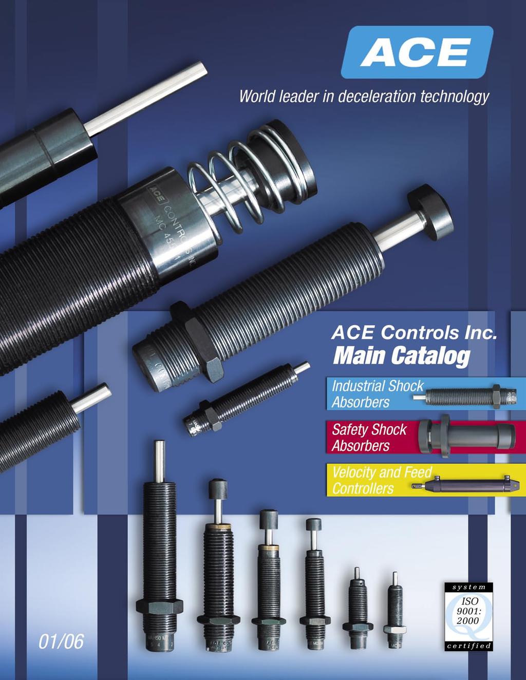
91
Index 2 General Information page Shock Absorber Function General Information
 ACE Controls self-compensating shock absorbers are fixed, multi-orifice units that decelerate moving weights smoothly regardless of changing conditions, and require no adjustment. These versatile performers
Industrial Shock Absorbers (Linear Decelerators)
") Industrial Shock Absorbers () Catalog AU08-1022-1/NA February, 2007 Compact Designs High Effective Weight Capability Industry Interchangeable Metric and UNF Threads Complete Line of Accessories Quality
Industrial Shock Absorbers () Catalog AU08-1022-1/NA February, 2007 Compact Designs High Effective Weight Capability Industry Interchangeable Metric and UNF Threads Complete Line of Accessories Quality
Miniature Shock Absorbers MC 5 to MC 75
 Miniature Shock Absorbers MC 5 to MC 75 Self-Compensating ACE Miniature Shock Absorbers are self-contained hydraulic units. The MC 5 to MC 75 model range has a very short overall length and low return
Ultra-High Energy Absorption SC 25 to SC 650 Heavyweight Shock Absorbers. Featuring New SC 25, 75 & 190 Models Features...
 Ultra-High Energy Absorption SC 5 to SC 650 Heavyweight Shock Absorbers Featuring New SC 5, 75 & 190 Models Features. Piston Tube Design for Long Cycle Life Stainless Steel Piston Rod Integral Mechanical
Automation Control Equipment
 Automation Control Equipment Main Catalog Edition 7/2014 Industrial Shock Absorbers New Models Safety Shock Absorbers TUBUS Profile Dampers New Models Dampers/ Feed Controls New Models Industrial Gas Springs
Table of Contents Industrial Shock Absorber
 Table of Contents Industrial Shock Absorber Page Technical informations 4 Survey 16 Non-adjustable Shock Absorber Type SA 10 N, SA 10 SN, SA 10 S2N 20 Type SA 12N, SA 12 SN, SA 12 S2N 22 Type SA 14, SA
MAC / MAD series MAC SHOCK ABSORBERS. Order example. TUBE O.D. (mm) STROKE (mm) Select damping constant from graph
 STROKE (mm) Select damping constant from graph") M / MD series SHOK SORRS Order example M 0806 1 TU O.D. MD: djustable M: Non-adjustable MD: Double cushion STROK Select damping constant from graph 1: Hight : Medium 3: Low S: -S series K: -K series lank:
M / MD series SHOK SORRS Order example M 0806 1 TU O.D. MD: djustable M: Non-adjustable MD: Double cushion STROK Select damping constant from graph 1: Hight : Medium 3: Low S: -S series K: -K series lank:
Industrial shock absorbers
 Industrial shock absorbers Safety shock absorbers Hydraulic speed controls General information Industrial shock absorbers, safety shock absorbers and hydraulic speed controls are used wherever masses have
Main Catalogue. Automation Control Equipment. New models. Edition 9/2004. Safety Shock Absorbers. TUBUS Bumpers. Rotary Dampers
 Automation Control Equipment Main Catalogue Edition 9/04 Industrial Shock Absorbers New models Safety Shock Absorbers TUBUS Bumpers New models Rotary Dampers New models Dampers / Feed Controls New models
Innovation in. Mechanical Motion & Vibration Controls
 Innovation in Mechanical Motion & Vibration Controls ACE Controls Inc. located in Farmington Hills, Michigan, is a leading innovator in deceleration, vibration and motion control technology. For over a
Elastomer Products for Energy Control
 TUBUS Bumpers Elastomer Products for Energy Control Outperform Rubber, Urethane and Coiled Steel ACE Controls Inc. Innovation in Deceleration and Motion Control ISO 9001 Certified 01/09(R) Revised 12/10
Automation Control Equipment
 Automation Control Equipment Main Catalogue Edition 9/07 Industrial Shock Absorbers Safety Shock Absorbers ew Models TUBUS Bumpers Rotary Dampers Dampers/ Feed Controls Industrial Gas Springs ew Models
WDS INDUSTRIAL SHOCK ABSORBERS. & : * 1-a. Deceleration technologies: WDS
 Benefits of using Industrial Shock Absorbers: Increased productivity through raised machine speeds, smoother operation and operator comfort. Smooth deceleration of moving parts leading to reduced wear,
Automation Control Equipment. Main Catalogue. Edition 4/2009. New Models. New Models. Industrial Shock Absorbers. Safety Shock Absorbers
 Automation Control Equipment Main Catalogue Edition 4/09 Industrial Shock Absorbers Safety Shock Absorbers TUBUS Profile Dampers New Models SLAB Damping Plates New Models Rotary Dampers Dampers/ Feed Controls
Shock Absorber Accessories M5 to M25
 Shock Absorber Accessories M to M 34 Selection Chart for Shock Absorber Accessories 1 Clamp Mount/ Universal Mount 2 Side Load Adaptor Shock Absorber Type KM AH MB RF UM BV Thread Size Mx0. MCEUM KM AH
Automation Control Equipment. Main Catalogue. Edition 6/2011. New Models. New Models. New Models. New Models. New Models. New Models.
 Automation Control Equipment Main Catalogue Edition 6/11 Industrial Shock Absorbers New Models Safety Shock Absorbers New Models LOCKED Clamping Elements TUBUS Profile Dampers New Models SLAB Damping Plates
USE AN ENGINEERED APPROACH TO TAILOR A PERFECT STANDARD GAS SPRING FOR YOUR DESIGN A GUIDE TO GAS SPRING DESIGN AND CUSTOMIZATION WH ITE PA P E R
 WH ITE PA P E R USE AN ENGINEERED APPROACH TO TAILOR A PERFECT STANDARD GAS SPRING FOR YOUR DESIGN A GUIDE TO GAS SPRING DESIGN AND CUSTOMIZATION When your machine design calls for an industrial gas spring,
TUBUS-Series Type TA
 TUBUS-Series Type TA Profile Damper Axial Damping 84 The profile damper type TA from the innovative ACE TUBUS series is a maintenancefree, self-contained damping element made from a special Co-Polyester
LOCKED SERIES. Machine Failures. General Information. set up. maintenance. reconditioning. repair 30.4%
 General Information LOCKED SERIES 2 Lowering machinery process costs is key in today s world. According to a recent study approximately a third of all machine stoppages result in unexpected damage and
Automation Control Equipment. Main Catalogue. Edition 1/2013. New Models. New Models. New Models. Industrial Shock Absorbers. Safety Shock Absorbers
 Automation Control Equipment Main Catalogue Edition 1/13 Industrial Shock Absorbers New Models Safety Shock Absorbers TUBUS Profile Dampers New Models SLAB Damping Plates Rotary Dampers Dampers/ Feed Controls
Miniature Shock Absorbers MC5 to MC75
 Miniature Shock Absorbers MC to MC7 1 ACE miniature shock absorbers are maintenance-free, self-contained hydraulic components. The model range MC to MC7 have a very short overall length and a low return
TUBUS-Series Type TA
 TUBUS-Series Type TA Profile Damper Axial Damping The profile damper type TA from the innovative ACE TUBUS series is a maintenancefree, self-contained damping element made from a special Co-Polyester Elastomer.
TUBUS-Series Type TA
 TUBUS-Series Type TA Profi le Damper Axial Damping 76 The profile damper type TA from the innovative ACE TUBUS series is a maintenance-free, self-contained damping element made from a special Co-Polyester
Hydraulic Shock Absorbers & Buffers
 www.izmac.co.kr Hydraulic Shock bsorbers & Buffers www.izmac.co.kr Best Engineered for Energy bsorption OVERVIEW s manufacturing process speeds up in every industry for better productivity and production
Safety Shock Absorbers SCS300 and 650
 s SCS300 and 650 60 The safety shock absorber series SCS300 to 650 are based on the innovative technology of the SC² series by ACE. y combining the piston and inner tube, an energy capacity up to 525 m
Heavy Duty Ball Screw Linear Actuators
 Heavy Duty Ball Screw Linear Actuators Thrust From 2,000 to 25,000 lbf Heavy Wall Steel Construction Longest Life Simultaneous High Thrust with High Speed Piston with Rugged Anti Rotation Feature Sealed
Shock Absorbers What is Ride Control Vehicle Dynamics Suspension System Shock Absorbers Struts Terminology
 Home Tech Support Shock Absorbers Shock Absorbers What is Ride Control Vehicle Dynamics Suspension System Shock Absorbers Struts Terminology A BRIEF HISTORY These first shock absorbers were simply two
TAKE IT TO THE NEXEN LEVEL
 TAKE IT TO THE NEXEN LEVEL INDUSTRIES SERVED Aerospace Automation Equipment Automotive Bottling CNC Machining Commercial Laundry Equipment Converting Conveying Food Processing Machine Tool Material Handling
ITT Industrial Products
 ITT Industrial Products Providing custom industrial solutions to meet customers application needs globally. ITT Control Technologies GmbH under the ITT Enidine brand provides quality energy absorption
RODLESS CYLINDER SERIES PU ACTUATORS
 RODLESS CYLINDER SERIES PU 1 RODLESS CYLINDER SERIES PU RODLESS CYLINDER SERIES PU Series PU rodless cylinders have an internal strip for longitudinal tightness made of polyurethane (PU) with a harmonic
Adjustable Series Hydraulic Shock Absorbers OEM Series. Adjustable Series OEM XT. Overview. Features and Benefits
 XT Hydraulic Shock Absorbers Series Overview Xtreme Mid-Bore Series Large Series Small Bore Platinum Series Enidine Adjustable Hydraulic Series shock absorbers offer the most flexible solutions to energy
Automation Control Equipment. Damping Technology. ACE: Your partner for industrial shock absorbers, hydraulic dampers and vibration control
 Automation Control Equipment Damping Technology ACE: Your partner for industrial shock absorbers, hydraulic dampers and vibration control Extract from Main Catalogue 206 Complete Product Range Data Sheets
EMC-HD. C 01_2 Subheadline_15pt/7.2mm
 C Electromechanical 01_1 Headline_36pt/14.4mm Cylinder EMC-HD C 01_2 Subheadline_15pt/7.2mm 2 Elektromechanischer Zylinder EMC-HD Short product name Example: EMC 085 HD 1 System = ElectroMechanical Cylinder
RE / STAR Tolerance Rings STAR Ball Knobs, Knob and Lever Type Handles
 RE 2 970/.99 STAR Tolerance Rings STAR Ball Knobs, Knob and Lever Type Handles STAR Tolerance Rings Product Overview Tolerance rings are made of hard, embossed spring steel strip and belong to the class
HYDRAULIC SHOCK ABSORBER
 Safe Silent Smooth Speed HYDRAULIC SHOCK ABSORBER The Last Brake for Uncontrolled Moving Object HANIL LUBTEC CO., LTD. www.hanillubtec.com Shock Absorption and Productivity I nevitably some motion is generated
Heavy Duty Shock Absorbers
 Heavy Duty Shock Absorbers Applications: Amusement ride emergency stops Transportation safety stops Ladle transfer cars Coil upenders/downenders Rolling mill chock separators Furnace slab bumpers Hot strip
Miniature Shock Absorbers MC5 to MC75
 Miniature Shock Absorbers MC5 to MC75 Self-Compensating ACE miniature shock absorbers are maintenance-free, self-contained hydraulic components. The model range MC5 to MC75 have a very short overall length
Small dampers refine end product
 4 Motion Control Small dampers refine end product ACE rotary dampers mainly provide an invisible yet valuable service as a maintenance-free machine element to allow controlled deceleration of rotary or
Miniature Shock Absorbers MC5 to MC75
 Miniature Shock Absorbers MC5 to MC75 1 ACE miniature shock absorbers are maintenance-free, self-contained hydraulic components. The model range MC5 to MC75 have a very short overall length and a low return
Heavy Duty Shock Absorbers
 Heavy Duty Shock Absorbers Applications: Amusement ride emergency stops Transportation safety stops Ladle transfer cars Coil upenders/downenders Rolling mill chock separators Furnace slab bumpers Hot strip
SRU-mini. Application example. Pneumatic Rotary Actuators Universal Rotary Actuators. Weight 0.15 kg 0.65 kg. Torque 0.16 Nm 1.
 SRU-mini Sizes 8 14 Weight 0.15 kg 0.65 kg Torque 0.16 Nm 1.15 Nm Axial force 255 N 330 N Bending moment 2.5 Nm 4.5 Nm Application example Reversing unit for the economical reorientation of cylindrical
CH16: Clutches, Brakes, Couplings and Flywheels
 CH16: Clutches, Brakes, Couplings and Flywheels These types of elements are associated with rotation and they have in common the function of dissipating, transferring and/or storing rotational energy.
EDVC Velocity and Feed Controllers
 EDVC Velocity and Feed Controllers Hydraulic Speed/Feed Controllers from Enertrols are selfcontained sealed units designed for precise control of speed in both directions of travel. The travel speed can
INDEX EASY RAIL: THE SOLUTION IS EASY...D4 EXAMPLES OF LOAD CAPACITIES...D5 ORDER CODES...D6 MOUNTING EXAMPLES...D7 TECHNICAL DATA...
 INDEX EASY RAIL: THE SOLUTION IS EASY...D4 EXAMPLES OF LOAD CAPACITIES...D5 ORDER CODES...D6 MOUNTING EXAMPLES...D7 TECHNICAL DATA...D8 STANDARD CONFIGURATIONS...D10 VERIFICATION UNDER STATIC LOAD...D12
Compact. Fast. Productive. DRL Lift/Swivel Unit
 DRL Compact. Fast. Productive. DRL Lift/Swivel Unit Compact lift/swivel unit consisting of a strong short-stroke cylinder and a rack pinion swivel drive. Field of Application For use in clean and slightly
COMPACT CYLINDER CYLINDER FORCE AND WEIGHT TABLE BASE WEIGHT EFFECTIVE AREA
 CRS COMPACT CYLINDER STROKE TOLERANCE TEMPERATURE LIMITS VELOCITY LIFE EXPECTANCY SERIES CRS 1 psi min to 15 psi max at zero load [.7 bar min to 1 bar max] air.31 inch [.8 mm] -2 to +18 F [-28 to +82 C]
PET Shock Absorbers. Ideal for Stretch Rod and Mold Applications. Lifetime Warranty. PET Shock Absorber Benefits. PET Shock Absorber Features
 Ideal for Stretch Rod and Applications 1 ACE Controls now offers a NEW GENERATION of industrial shock absorbers for the PET container industry. These durable models are ideally suited for stretch rod and
Brake Systems Application Guide INDEX BRAKE SUMMARY AND KEY FEATURES 3 TYPICAL DESCRIPTION AND APPLICATIONS HYDRAULIC BRAKES 4-7
 INDEX INTRODUCTION BRAKE SUMMARY AND KEY FEATURES 3 TYPICAL DESCRIPTION AND APPLICATIONS HYDRAULIC BRAKES 4-7 TYPICAL DESCRIPTION AND APPLICATIONS ELECTRIC BRAKES 8 BRAKE CALCULATIONS SELECTING BRAKE TORQUE
Overview of Profi le Dampers TR/TR-L
 TUBUS-Series Overview of Profi le Dampers Physical Properties of TUBUS Profile Dampers Energy Capacity per unit weight Operating Lifetime PUR Rubber Gummi TUBUS Energy Capacity per unit volume ACE TUBUS
Shock and Vibration Products
 Shock and Vibration Products ITT Enidine provides quality energy absorption and vibration isolation products and services to a variety of heavy industries throughout the globe. These industries include;
ORIGA Pneumatic Linear Drives OSP-L
 ORIGA Pneumatic Linear Drives OSP-L Very long lifetime and lowest leakage A NEW Modular Linear Drive System With this second generation linear drive Parker Origa offers design engineers complete flexibility.
Servo-Hydraulic Vibration Test Equipment
 Servo-Hydraulic Vibration Test Equipment We build vibration test equipment that performs The tests YOU need to do To evaluate the package YOU have designed To protect the product YOU must get to market
Table of Contents Product Selection
 Table of Contents Product Selection Company Overview...................................................................... 1 New Technologies and Enhancements................................................
Rotary-Linear Actuator HSE4 Hydraulic / 100 Bar
 Rotary-Linear Actuator HSE4 Hydraulic / 100 Bar 4 Function and features K A1 G1 B1 G2 KM Y B2 RE A2 Z S2 A S1 W B KS [ Operation ] [ Operating pressure ] The Eckart rotary-linear actuator HSE4 is a combination
210C-1 Selection materials
 7 2C- Selection materials 8 Calculation of cylinder buckling ) Be sure to calculate the cylinder buckling. 2) In the case of using a hydraulic cylinder, the stress and buckling must be considered depending
Seals Stretch Running Friction Friction Break-Out Friction. Build With The Best!
 squeeze, min. = 0.0035 with adverse tolerance build-up. If the O-ring is made in a compound that will shrink in the fluid, the minimum possible squeeze under adverse conditions then must be at least.076
Linear Drive with Ball Screw Drive Series OSP-E..SB
 Linear Drive with Ball Screw Drive Series OSP-E..SB Contents Description Data Sheet No. Page Overview 1.30.001E 47-50 Technical Data 1.30.002E-1 to 5 51-55 Dimensions 1.30.002E-6, -7 56-57 Order instructions
TRANSLATION (OR LINEAR)
") 5) Load Bearing Mechanisms Load bearing mechanisms are the structural backbone of any linear / rotary motion system, and are a critical consideration. This section will introduce most of the more common
5) Load Bearing Mechanisms Load bearing mechanisms are the structural backbone of any linear / rotary motion system, and are a critical consideration. This section will introduce most of the more common
Introduction to hmtechnology
 Introduction to hmtechnology Today's motion applications are requiring more precise control of both speed and position. The requirement for more complex move profiles is leading to a change from pneumatic
Test Which component has the highest Energy Density? A. Accumulator. B. Battery. C. Capacitor. D. Spring.
 Test 1 1. Which statement is True? A. Pneumatic systems are more suitable than hydraulic systems to drive powerful machines. B. Mechanical systems transfer energy for longer distances than hydraulic systems.
Pneu-Turn Rotary Actuators
 Pneu-Turn Rotary Actuators Pneu-Turn Actuators 4.3-4.14 Three-Position Pneu-Turn 4.15-4.17 Engineering Specifications/ Application Checklist 4.18-4.21 TURN TO THE BIMBA PNEU-TURN ROTARY ACTUATOR FOR THESE
RACK JACK. Synchronous Lifting Systems
 RACK JACK Synchronous Lifting Systems RACK JACK (ROUND RACK TYPE) Operation The Rack Jack from WMH Herion provides simple synchronous lifting motion. The system of rack and pinion transforms linear motion
GSM. Modular Design. Versions of the series. Type GSM. Gripper type P Z W R. Size. {} AS IS without O.D. clamping I.D. clamping
 GSM Pneumatic Gripper-Swivel System Modular Design Versions of the series Type GSM Gripper type P Z W R Size 32 40 50 64 30 38 45 16 20 25 32 40 16 20 25 32 40 Gripping force safety device {} AS IS without
THE BEST MOVES IN THE WORLD
 THE BEST MOVES IN THE WORLD UNDERHUNG & TOP RUNNING CRANES STACKER CRANE SYSTEMS MONORAILS `SPECIALIZED AVIATION MAINTENANCE CRANES SPECIALIZED LAUNDRY & OVERHEAD MATERIALS HANDLING THE RIGHT MOVE TC/American
Magnetic particle clutches and brakes
 Accurate torque control with instantaneous engagement! Warner Electric Precision Tork magnetic particle clutches and brakes are unique because of the wide operating torque range available. Torque to current
Gas-liquid Hybrid Buffers Series HD. Working Principal. Application C
 C3.0 Gas-liquid Hybrid Buffers Series HD Working Principal During the initiated stage, there will be a certain volume of nitrogen in the gas chamber, and a certain volume of hydraulic oil in the oil chamber.
Kaydon white paper. Slewing bearing selection, simplified. an SKF Group brand. by Jeff Lauber, engineering specialist
 Slewing bearing selection, simplified by Jeff Lauber, engineering specialist an SKF Group brand Selecting the right slewing bearing Slewing bearings are typically used in applications where their ability
VRX Vane rotary actuator
 VRX Vane rotary actuator Corrosion Resistant External Components MAXIMUM DURABILITY What You Expect from the pneumatic actuator Leader: Tolomatic offers a complete line of linear motion products. We offer
The University of Melbourne Engineering Mechanics
 The University of Melbourne 436-291 Engineering Mechanics Tutorial Twelve General Plane Motion, Work and Energy Part A (Introductory) 1. (Problem 6/78 from Meriam and Kraige - Dynamics) Above the earth
Actuator Capabilities
 Actuator Capabilities The Compact Difference... Compact Automation Products brand, is a market-leading manufacturer of space-efficient linear actuator solutions including, industry standard and custom
Planetary Roller Type Traction Drive Unit for Printing Machine
 TECHNICAL REPORT Planetary Roller Type Traction Drive Unit for Printing Machine A. KAWANO This paper describes the issues including the rotation unevenness, transmission torque and service life which should
Linear Motion. Optimized.
 Thomson - Linear Motion. Optimized. Linear Motion. Optimized. Often the ideal design solution is not about finding the fastest, sturdiest, most accurate or even the least expensive option. Rather, the
Precise. Compact. Reliable. MPZ Small Components Gripper
 MPZ Precise. Compact. Reliable. MPZ Small Components Gripper Small 3-finger centric gripper with base jaws guided on T-slots Field of Application F or universal use in clean to slightly dirty working environments,
The Latest Sensor Trends
 Sensing & Feedback Technologies The Latest Sensor Trends Agenda Miniature sensors open up new applications Alternatives to Fiber optics Pneumatic cylinder sensing: Dual systems, analog and lifetime warranties
Sizes Weight Gripping moment Angle per jaw Workpiece weight Pieces : 1 20 kg 180 Nm kg. PZH-SF Finger Centric Gripper
 Sizes Weight Gripping moment Angle per jaw Workpiece weight Pieces : 1 20 kg 180 Nm 59.7 8 kg Application example PZH-SF 350 3-Finger Centric Gripper Gamma Gantry Linear Module Gamma Gantry Linear Module
Selecting the Optimum Motion Control Solution for the Application By Festo Corporation
 Selecting the Optimum Motion Control Solution for the Application By Festo Corporation The successful machine builder develops products that offer superior price, performance, reliability, and the ability
Rodless Pneumatic Cylinders Series OSP-P
 Rodless Pneumatic Cylinders Series OSP-P System Concepts & Components... 2-5 Technical Data... 7-9 Dimensions... 10-15 Active rakes... 16-19 Accessories (Mounts & Supports)... 20-29 Ordering Information...30
Application Description
 -14 Type, Intelligent Technologies (IT.) Soft Starters February 2007 Contents Description Page Type, Intelligent Technologies (IT.) Soft Starters Product Description....... -14 Application Description....
S PEED R EGULATORS F OR M OVING D EVICES. Bulletin S-66
 D E S C H N E R S PEED R EGULATORS F OR M OVING D EVICES L EAKPROOF H YDRAULIC C HECKS F OR S PEED R EGULATION O F M OVING D EVICES COMPACT & POWERFUL KINECHEKS are unequalled for controlling the speed
Rotary Indexing Table with Face Gear
 FIBROTAKT Rotary Indexing Table with Face Gear Product No. 1.001.00.00.00.01000 1 7975 006 4 08/007 Contents FIBRO The latest technology with a tradition of service /3 FIBROTAKT at a glance 4 Technical
Bisnet Solutions for Tomorrow, Today! The Die Casting Process Planner. Users Manual. August 5, A Product By: Bisnet - 1 -
 Bisnet Solutions for Tomorrow, Today! The Die Casting Process Planner Users Manual August 5, 2002 A Product By: Bisnet - 1 - DCPP Users Manual Table of Contents CHAPTER 1 PQ 2 4 What is PQ Squared? 4 CHAPTER
White Paper: The Physics of Braking Systems
 White Paper: The Physics of Braking Systems The Conservation of Energy The braking system exists to convert the energy of a vehicle in motion into thermal energy, more commonly referred to as heat. From
MultiCam 3000 Series CNC Router Feature and Specification Guide. Versatile, Feature-Rich Production Routing! The MultiCam. Ideal for Cutting: Wood
 MultiCam 3000 Series CNC Router Feature and Specification Guide Versatile, Feature-Rich Production Routing! The MultiCam 3000 Series CNC Routers are loaded with standard features normally associated with
Airflex Air Cooled Disc Clutches and Brakes
 Airflex Air Cooled Disc Clutches and Brakes DBA Description... 183 DBA Brake Elements... 185 DBA Technical information... 186 DBB and DBBS Description... 187 DBB Brake Elements... 189 DBB Technical Information...
Chapter 7: DC Motors and Transmissions. 7.1: Basic Definitions and Concepts
 Chapter 7: DC Motors and Transmissions Electric motors are one of the most common types of actuators found in robotics. Using them effectively will allow your robot to take action based on the direction
ROTARY MODULES. Rotary modules
 Rotary modules Rotary modules ROTARY MODULES Series Size Page Rotary modules RM swivel unit 156 RM 08 160 RM 10 162 RM 12 164 RM 15 168 RM 21 172 RM rotor 176 RM 50 180 RM 110 182 RM 200 184 RM 310 186
1. Product overview Basic-Line-Module AXN Product description Basic-Line-Module AXN 4-5. Guide system Roller guide 6 Drive system Gear belt 7
 Directory Page 1. Product overview Basic-Line-Module AXN 3 2. Product description Basic-Line-Module AXN 4-5 Guide system Roller guide 6 Drive system Gear belt 7 3. Basic-Line-Modul AXN 45-Z 8-9 AXN 65-Z
Industrial Shock Absorbers MC 33 to MC 64
 Industrial Shock Absorbers MC 33 to MC 64 Self-Compensating 36 This range of self-compensating shock absorbers is part of the innovative MAGNUM Series from ACE. You profit from the enhanced product life
PTR Series Pneumatic Rack & Pinion Rotary Actuator
 zact14 Pneumatic Rack & Pinion Rotary Actuator Contents Features... 2 Specifications... 3 Dimensions... 4 Mounting Options... 5 Shaft Options... 6 Port Size and Location... 7 Cushions and Bumpers... 8
ElJay Rollercone Classic and ElJay Rollercone II 36, 45, 54, 60, 66 ELJAY ROLLERCONE
 ElJay Rollercone Classic and ElJay Rollercone II 36, 45, 54, 60, 66 ELJAY ROLLERCONE ELJAY ROLLERCONE OFTEN IMITATED, NEVER EQUALED INCREASED OUTPUT FROM ADVANCED ENGINEERING The TEREX Cedarapids ElJay
PRECISION BELLOWS COUPLINGS
 PRECISION BELLOWS COUPLINGS Bellows couplings are used where precise rotation, high speeds, and dynamic motion must be transmitted. They exhibit zero backlash and a high level of torsional stiffness, offering
test with confidence HV Series TM Test Systems Hydraulic Vibration
 test with confidence HV Series TM Test Systems Hydraulic Vibration Experience. Technology. Value. The Difference. HV Series TM. The Difference. Our philosophy is simple. Provide a system designed for optimum
Miniature Shock Absorbers
 1 Automation Control Tuning for almost any design Miniature shock absorbers from ACE are tried-and-tested quality products used in millions of industrial construction designs throughout the world. They
TE 73 TWO ROLLER MACHINE
 TE 73 TWO ROLLER MACHINE Background The TE 73 family of machines dates back to original Plint and Partners Ltd designs from the 1960s. These machines are all to the overhung roller design in which test
Code No: R Set No. 1
 Code No: R05310304 Set No. 1 III B.Tech I Semester Regular Examinations, November 2007 KINEMATICS OF MACHINERY ( Common to Mechanical Engineering, Mechatronics, Production Engineering and Automobile Engineering)
R310EN 2211 ( ) The Drive & Control Company
 The Drive & Control Company") eline Ball Rail Systems R310EN 2211 (2006.04) The Drive & Control Company Bosch Rexroth AG Linear Motion and Assembly Technologies Ball Rail Systems Roller Rail Systems Linear Bushings and Shafts Ball
eline Ball Rail Systems R310EN 2211 (2006.04) The Drive & Control Company Bosch Rexroth AG Linear Motion and Assembly Technologies Ball Rail Systems Roller Rail Systems Linear Bushings and Shafts Ball
Engineering & Design Data
 PVC & CPVC Corrosion Resistant Industrial Pressure Pipe Engineering & Design Data Engineering & Design Data Hydraulic Shock Hydraulic shock is the term used to describe the momentary pressure rise in a
Shock Absorber & Gas Spring
 07 & 1. Data [7] - 2 (Adjustable) /, [7] - 7 (Non-adjustable) / KSCA [7] - 12 Costant Speed Controller / [7] - 16 2. Data [7] - 18 / KBG-W10, W20 [7] - 21 / KBG-B20, B22 [7] - 24 Data Operating Principles
MARITIME AFTERNOON. Torben Ole Andersen. June 14, 2017 Aalborg University, Denmark
 MARITIME AFTERNOON HYDRAULICS Torben Ole Andersen June 14, 2017 Aalborg University, Denmark Agenda Marine Propellers Digital Hydraulics in a Hydraulic Winch Secondary Control in of Multi -Chamber Cylinders
Precision Modules PSK
 Precision Modules PSK The Drive & Control Company Rexroth Linear Motion Technology Ball Rail Systems Roller Rail Systems Standard Ball Rail Systems Super Ball Rail Systems Ball Rail Systems with Aluminum