Brake Systems Application Guide INDEX BRAKE SUMMARY AND KEY FEATURES 3 TYPICAL DESCRIPTION AND APPLICATIONS HYDRAULIC BRAKES 4-7
|
|
|
- Lesley Ball
- 5 years ago
- Views:
Transcription

1
2 INDEX INTRODUCTION BRAKE SUMMARY AND KEY FEATURES 3 TYPICAL DESCRIPTION AND APPLICATIONS HYDRAULIC BRAKES 4-7 TYPICAL DESCRIPTION AND APPLICATIONS ELECTRIC BRAKES 8 BRAKE CALCULATIONS SELECTING BRAKE TORQUE BASED ON MOTOR DATA 9 CRANE HOIST BRAKING TORQUE 9 CRANE TROLLEY BRAKING TORQUE 10 SELECTING BRAKE SIZE BASED ON LOAD DATA 10 OVERHAULING LOAD TORQUE 1 BRAKE THERMAL CAPACITY 13 OVERHAULING LOADS 14 HYDRAULIC BRAKE SELECTION FOR BRIDGE BRAKES 15 HYDRAULIC BRAKE TORQUE RATINGS AND THERMAL CAPACITIES 16 DC MAGNETIC SHOE BRAKE TORQUE RATINGS AND THERMAL CAPACITIES 0 NOTE: Pages 9 through 14 describe brake calculations that in general apply to all style Gemco brakes. The hydraulic brake selection, pages 15 through 19 are specifically for hydraulic brakes used as bridge brakes for overhead cranes.
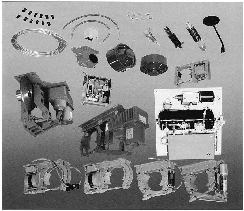
3 BRAKE SUMMARY AND KEY FEATURES HYDRAULIC, MAGNETIC, AND ELECTRO-THRUST BRAKE SYSTEMS Gemco Industrial Brakes stop virtually any type of industrial machine. Applications such as indoor and outdoor bridge cranes, gantries, heavy-duty cranes, high duty cycle cranes, lock and dam projects, stacker reclaimers, commercial laundry equipment, and heavy-duty industrial transfer equipment are just some of the uses for Gemco Industrial Brakes. These field-proven, high performance brake systems are tough and reliable, and they provide extended, trouble-free service. That s because they are designed and built to exacting specifications by Gemco. For more than 40 years, Gemco has been an acknowledged leader in brake systems technology for heavy-duty industrial applications. BRAKE SYSTEM KEY FEATURES SUMMARY H HM AH AHM CB TM ET S DB Hydraulically Applied Spring Applied Controlled Stopping Parking AISE Rated H - Manual Hydraulic Applied Brake System HM - Manual Hydraulic Brake with Parking AH - Air-Over-Hydraulic Brake System, for remote control AHM - Air-Over-Hydraulic Brake with Parking CB - AC Brake, Spring Set TM - DC Brake, Spring Set (Auxiliary Hydraulic Cyl. available) ET - Electro-Thrust, Spring Set Release by Electro-Hydraulic Actuator (Auxiliary Hydraulic Cylinder Available) DB - Electro-Thrust, Spring Set Release by Electro-Hydraulic Actuator (Auxiliary Hydraulic Cylinder Available) Note: Custom design and special brake assemblies are available; please consult factory for application assistance. 3

4 TYPICAL DESCRIPTION AND APPLICATIONS HYDRAULIC BRAKES Type H manually operated hydraulic brakes for smooth controlled service stops. Sizes are 6 through 18 with torque ratings 150 to 900 ft-lbs.; one and two brake systems. Bridge brakes for overhead, gantries and heavy duty cranes. The hydraulic brakes described in the following pages have been utilized for many years in steel mill cranes, shipyards and other applications where an operator control stop is desirable. Type HM brakes not only provide smooth controlled stopping but are also equipped with a spring applied parking actuator. Sizes for single brake systems 6 through 18, two brake systems 6 and 8. Bridge brakes for outdoor cranes that require parking feature due to wind loads. 4
5 Type AH-ARC (Air/Hydraulic Air Remote Control) brake system for stopping large loads. Sizes one, two and four brake systems - 6 through 18. Large overhead crane brakes for ladle cranes and other hot metal cranes, usually four brakes systems. Type AH-H RC (Air/Hydraulic- Hydraulic Remote Control) brake systems with operator hydraulic control. Sizes one, two and four brake systems - 6 through 18. Bridge brakes for overhead crane with moving trolley cabs that require more than 60 feet travel. 5
6 Type AH-ERC systems for operating hydraulic brakes by radio or pendent control. Size one, two and four brake systems - 6 through 8 brake. Any remote radio or pendent control brake requirement for bridge brakes. Type AH-ERC Conversion package adds remote control capability to existing H brake systems. Size one and two brake systems. Field modification for remote control capabilities on existing manual system. 6
7 Type AHM System. All three of the previously described air over hydraulic systems can be provided with parking. (AHM- ARC, AHM-HRC, and AHM- ERC). As previously described but with parking for outdoor crane applications. Type TMH System for remote operation of D.C. Electric Brake assemblies. Auxiliary cab control also allows hydraulic operation for controlled braking. sizes are 4 to 3, one and two brake systems. Bridge brakes for overhead cranes. Since electric brake is spring set, parking feature is also present. Note: Auxiliary cab control is also available for EH style electro-thrust brakes. 7


8 Type CB brakes spring applied electrically released via solenoid. Sizes, 4 ½ to 10, general duty. Light duty crane bridge brakes and holding brakes. Type TM brakes spring applied electrically released via D.C. magnet coils. AISE sizes, Mill Duty. Crane hoist, stationary hoist, drive roller brakes, and lock and dam motor brakes. Type ET brake spring applied electrical release by A.C. or D.C. electro-thrust mechanism. Bridge brakes, lock and dam project, stacker reclaimers, container cranes. Note: Auxiliary hydraulic cylinder is also available for manual cab control. Type DB brake spring applied electrical release by A.C. or D.C. electro-thrust mechanism. Bridge brakes, lock and dam project, stacker reclaimers, container cranes. Note: Auxiliary hydraulic cylinder is also available for manual cab control. 8
9 INTRODUCTION When selecting the proper brake for a specific application, there are several factors to consider; a few that need to be reviewed are brake torque, stopping time and/or deceleration rates, brake mounting, brake location, thermal rating, environment, and brake style. The brake systems manufactured by Gemco Industrial Brake Products are external friction brakes. Applications for which these brakes are suited can be classified into two general categories: non-overhauling and overhauling. A) Non-overhauling loads are typically horizontally moving masses such as crane bridges, crane trolleys, and horizontal conveyors. B) Overhauling loads tend to run up in speed if a brake is not present, examples of which are crane hoists, winches, lifts, and downhill conveyors. Type A (non-overhauling) loads require brake torque only to stop the load and will remain at rest due to friction. Type B (overhauling) loads have two torque requirements; the first is braking torque required to stop the load, and the second is the torque required to hold the load at rest. SELECTING BRAKE TORQUE BASED ON MOTOR DATA The full -load torque of a motor is a function of horsepower and speed and is commonly used to determine a brake torque rating. The brake torque rating is to equal or exceed the full load torque of a motor. The formula to calculate the full load motor torque is as follows: T = 550 x HP x S.F. RPM where: 550 = constant HP = motor horsepower RPM = speed of motor shaft S.F. = application service factor T = static brake torque CRANE HOIST BRAKING TORQUE Sizing of crane hoist brakes is typically based upon full load hoisting torque. The following is a brief summary of guidelines for hoist brakes. Each hoist on a crane should be equipped with at least one spring-set magnetic brake; hoists handling hot metal should be equipped with more than one brake. Brake rating expressed as a percent of hoisting torque at the point of brake application should be no less than the following: 1) 150% when only one brake is used. ) 150% when multiple brakes are used and the hoist is not used to handle hot metal. Failure of any one brake shall not reduce braking torque below 100%. 3) 175% for hoists handling hot metal. Failure of any one brake shall not reduce brake torque below 15%. 9
10 CRANE TROLLEY BRAKING TORQUE Crane trolley brakes are typically sized with a torque rating less than the motor s full load torque (service factor less than 1.0) to provide a longer stopping time or a soft stop. Overhead crane trolley brakes are minimized to prevent sway of the hook and load. Typical service factor is 50% for soft stopping. SELECTING BRAKE SIZE BASED ON LOAD DATA For applications where high inertial loads exist or where a specific stopping time or distance is required, the brake should be selected based on the total inertia of the load. Total system inertia reflected to the brake shaft can be expressed as follows: WK T where: WK T WK B WK M WK L = WK B + WK M + WK L = Total reflected inertia to brake (Ib-ft ) = Inertia of brake wheel (Ib-ft ) = Inertia of motor rotor (Ib-ft ) = Equivalent inertia of load reflected to shaft (lb-ft ) brake The following formulas apply when calculating inertia of systems with different rotational speeds or linear moving loads to brake shaft speeds. Rotary Motion: WK b = WK L (N L / N B ) where: WK b = Inertia of rotation load reflected to brake shaft (lb-ft ) WK L = Inertia of rotating load (lb-ft ) N L = Shaft speed at load (RPM) N B = Shaft speed at brake (RPM) 10
11 Horizontal Linear Motion: WK W = W (V / pn B ) where: WK W = Equivalent inertia of moving load reflected to brake shaft (lb-ft ) W = Weight of linear load (Ib) V = Linear velocity of load (ft/mm) N B = Shaft speed at brake (RPM) With the total system inertia calculated, the required average dynamic torque for a desired stopping time can be calculated using the following formula: T d = WK T x NB 308 x t where: T d = Average dynamic braking torque (lb-ft) WK T = Total inertia reflected to brake (lb-ft ) N B = Shaft speed at brake (RPM) t = Desired stopping time (sec.) 308 = Constant To determine stopping time for a given brake torque this formula can be rewritten as follows: t = WK T * N B 308 x Td For some brake styles the time required until the brake lining makes contact with the wheel may be significant. Time required to stop is then as follows: WK T xnb t = t x Td where: t 1 = Time between signal and moment when brake torque is actually applied (sec.) 11
12 For linear applications, the dynamic braking torque can be calculated directly using the following formula: W x V x r T d = g x t where: T d = Average dynamic braking torque (lb-ft) W = Total weight of linear moving load (lb.) V = Linear velocity of load (ft/sec.) g = Gravitational acceleration constant (3. ft/sec) t = Desired stopping time (sec.) r = Length of movement arm or wheel radius (ft.) This formula is applicable on crane trolley or crane bridge brakes. OVERHAULING LOAD TORQUE Applications with a descending load, such as crane hoists, elevators, etc., require a brake with sufficient torque both to stop the load and to hold it at rest. The total system inertia reflected to the brake shaft speed should be calculated using the previous formulas. Next, the average dynamic torque should be calculated with the previous formula: T d = WK T * N B 308 * t Next, the overhauling torque reflected to the brake shaft can be determined by the following formula: * W * V T o = N B where: T o = Overhauling dynamic torque of load reflected to brake shaft (lb-ft) W = Weight of overhauling load (lb.) V = Linear velocity of descending load (ft/min.) N B = Shaft speed at brake (RPM) = Constant (1/ p) 1
13 The total dynamic torque required for an overhauling load is the sum of T d and T 0, as follows: T t = T d + T o where: T t = Total dynamic torque for descending load BRAKE THERMAL CAPACITY When a brake stops a load, the energy required to stop is converted to heat. This heat is absorbed by the brake and the wheel. The ability to absorb and dissipate heat without exceeding temperature limitations is known as thermal capacity. There are two types of thermal capacity. The first is referred to as the maximum energy the brake can absorb in one stop, or emergency stop. The second is the heat dissipation capability of the brake if it is for frequent stopping. The kinetic energy that must be absorbed and dissipated by the brake can be determined as follows: Rotational Loads: KE r = WK T X N B 5875 where: KE r = Kinetic energy of rotating load (ft-lb) WK T N B = Inertia of the rotating load reflected to brake shaft (Ib-ft ) = Shaft speed at brake (RPM) 5875 = Constant W x V KE L = g where: KE L = Kinetic energy (ft-lb) W V = Weight of load (lb.) = Linear velocity of load, (ft/sec.) g = Gravitational constant (3. ft/sec ) 13
14 OVERHAULING LOADS In the case of overhauling loads, both the kinetic energy of the linear and rotating loads and the potential energy transformed into kinetic energy by the change in height must be considered. The potential energy transformed to kinetic energy is determined as follows: PE = WS Where: PE = Change in potential energy, (ft-ib) W = Weight of overhauling load (Ib) S = Distance load travels (ft.) Therefore, the total energy to be absorbed by the brake in stopping an overhauling load is: ET = KE L + KE r + PE In general, a brake will repetitively stop a load at the duty cycle that the electric motor can repetitively start the load. For rotating or linear loads, the rate at which a brake is required to absorb and dissipate heat when frequently cycled is determined as follows: where: WK T x N B x N O T C = 3,0,000 TC = WK T Thermal capacity (HP - sec/min) = Total system inertia (Ib-ft ) N B = Shaft speed at brake (RPM) N 0 = Number of stops per minute 3,0,000 = Constant For overhauling loads the rate at which the brake is required to absorb and dissipate heat when frequently cycled is determined as follows: TC = E T x N O 550 where: TC = Thermal capacity (HP-sec/min) E T = Total energy brake absorbs (ft-ibs) 550 = Constant N 0 = Number of stops per minute 14
15 BRAKE SELECTION FOR BRIDGE BRAKES The following formulas apply for calculating linear loads such as bridge brake applications: W x V KE L = T x g d = where: KE L = Kinetic energy (ft-lb) W x V x r g x t W = Weight (lb.) V = Linear velocity (ft/sec) G = Gravitational constant (3. ft/sec ) R = Wheel radius (ft) T = Stopping time T d = Average dynamic torque (lb-ft) Given in terms of tons, wheel diameter, gear ratios, etc., the specifications necessary to calculate crane bridge brakes include the following: Empty crane weight WE Tons Full load crane weight WL Tons Max. bridge speed FPM Ft/Min. Stops per hour N Number value Track wheel diameter DIA Inches *Gear ratio brake shaft to track wheel R (To 1) Number of brakes NB Number value Acceleration rate A Ft/Sec. Min. deceleration rate d MN Ft/Sec. Max. deceleration rate d MX Ft/Sec. Drive motor inertia WK M (Lb-Ft ) * Drive motor RPM can be used to verify gear ratios, etc., for a maximum speed and track diameter. In general, service bridge brakes should have sufficient thermal and torque range to stop the bridge within a distance of 10% of the full load speed with full load, or at a deceleration rate as specified by the original manufacturer. 15
16 The kinetic energy and torque calculations can be stated in terms of crane specifications as follows: Kinetic energy absorption rate, per brake per hour: KE = N x (FPM) x (WE + WL) 3 x NB Minimum stopping torque (to stop empty crane at minimum deceleration rate): T MN =.59 x WE x d MN x DIA NB x R Maximum stopping torque (to stop fully loaded crane at maximum deceleration rate): T MX =.59 x WL x d MX x DIA NB x R HYDRAULIC BRAKE TORQUE RATINGS AND THERMAL CAPACITIES Using the table below, select the smallest brake size that will exceed KE and TMX calculations listed above. TMN calculations for air powered systems should be above Minimum torque limits below: Brake Size Max. KE per Brake per Hour (ft.-ib) Type H 1- Brake Max. Dynamic Torque per Brake (Ib-ft.)** Type H -Brake or Type HM All Air Powered Min. Dynamic Torque, All Air Powered Systems (lb-ft.) 6 x x x x x 4.5 x x x x x **Based on 70 lb. pedal force, 8 max. pedal travel on Type H or HM manual systems. 16
17 Maximum stops per hour can be calculated using the following: N x (Max. KE per brake per hour) Max. stops/hr. = KE where: (Max. KE per brake per hour) = Value for brake size as shown in table above. The additional torque required to stop the drive rotor and the brake wheel inertia is normally insignificant and is ignored when the gear ratio (R) is less than about 10 x 1. If the gear ratio, and thus the drive rotor inertia is abnormally high, considerable torque may be needed just to stop the drive rotor. To calculate the additional torque needed to stop the drive rotor and brake wheel inertia, proceed as follows: 1. Complete the previous calculations to establish the prelimary brake size. BRAKE SIZE BRAKE WHEEL INERTIA 6 x 3.55 lb-ft. 8 x Lb-Ft. 10 x Lb-Ft. 14 x Lb-Ft. 18 x Lb-Ft.. Record the following data from brake wheel inertia table above and additional data from previous calculations. WK Brake wheel Inertia Lb-Ft. WK Drive Rotor Inertia + Lb-Ft. WK Total (Drive Motor and Wheel) Lb-Ft. R, Gear Ratio x1 d MN Deceleration Rate ft/sec. d MX Deceleration Full Load ft/sec. DIA, Track Wheel inches 3. Calculate No Load Drive Torque, T NLD : WK Total x R x d MN = x x 1.34 x DIA. = Lb-Ft x 4. Calculate Full Load Drive Torque, T FLD : TNLD X d MX d MN = x = Lb-Ft. 17

18 5.Calculate Total Minimum and Maximum Torques: T MN (previous) Lb-Ft. T MX (previous) Lb-Ft. T NLD + Lb-Ft. T FLD + Lb-Ft. T MNT Lb-Ft. T MxT Lb-Ft. 6.Check to determine that T MxT is still within the torque limits of the brake size selected. If necessary, recalculate the problem based on alternate brake size and brakewheel inertia. The chart below shows the dynamic torque values developed by manually operated brake systems. Maximum torques tabulated are developed at 70 lb. pedal force, the limit indicated by AISE and OSHA. Two maximum values are shown for 10 x 4, 14 x 6, and 18 x 8 brakes, as follows: The chart below shows the dynamic torque ranges developed by air powered hydraulic systems. The maximum torques shown are developed by a 70 lb. force applied on the air treadle on Type A/H systems or applied on the pedal of the control cylinder on Type NHM-HRC systems. Air powered hydraulic systems include either a 1 x 5 or a 1 x 8 air hydraulic pressure cluster to apply the service brake. In addition, 10, 14, and 18 brakes include either a 7/8 diameter or a 1-1/8 diameter service brake actuator. Hence, 6 and 8 brakes have two possible maximum torque limits, while 10, 14, and 18 have four possible maximum torque limits. The minimum torque limits shown are developed by light application of the treadle or pedal. Because of hysteresis and friction in the power system valves, it is not practical to consistently control less torque than the minimum calculated. 18

19 Static holding torque values tabulated below are those developed by the parking spring on the Type HM brakes. The brake must be correctly adjusted in order to get the holding torque tabulated. Brake Size 6 x 3 8 x 3 10 x 4 14 x 6 18 x 8 Holding Torque, lb-ft
20 TM, ET and DB SHOE BRAKE TORQUE RATINGS AND THERMAL CAPACITIES TM Torque Ratings ET Torque Ratings TM 43 TM 63 TM 83 TM 1035 TM 1355 TM 1655 TM 1985 TM 311 TM 3014 Maximum Torque in Lbs.-Ft (Max.) Series Brake Shunt Brake 1/ HR 1 HR 1 HR 8 HR BRAKE STYLE WHEEL DIAMETER (inches) TORQUE LB.FT. (Max.) ET ET ET ET ET ET ET Allowable Heat Absorption for Brake Wheels Wheel Ft.-Lb. Size per Hour , , , ,716, ,300, ,016, ,45, ,890, ,150,000 DB Torque Ratings BRAKE STYLE DISC DIAMETER (Inches) TORQUE LB.FT. (Max.) DB DB DB AMETEK PATRIOT SENSORS 6380 BROCKWAY ROAD PECK, MI USA Fax
Crane Control Class 5010
 WB F s and Rectifiers Catalog CONTENTS Descriptions....................................................Page DC Magnetic Drum s General Information................................................. 14 Pricing
MELDRO Hy-Thrust TM 3 Phase Electro-Hydraulic Actuators
 MELDRO Hy-Thrust TM 3 Phase Electro-Hydraulic Actuators General Information MELDRO Hy-Thrust Actuators are electro-hydraulic devices which combine all the basic elements of a hydraulic system into one
Section 15 Unit Selection Procedures
 APC-2006 All Products Catalog Section 15 Unit Selection Procedures Main Office and Manufacturing Plant 3660 Dixie Highway Fairfield, Ohio 45014 Telephone: (513) 868-0900 Fax: (513) 868-2105 E-Mail: info@forcecontrol.com
Crane Control. Obsolete-For Refenence use only-contact EC&M Company, LLC for more information
 Obsolete-For Refenence use only-contact EC&M Company, LLC for more information Crane Control CONTENTS Description.................................................... Page Selection Guide......................................................3
Stearns Heavy Duty Clutches & Brakes... Rugged, Reliable
 Stearns Heavy Duty Clutches & Brakes... Rugged, Reliable Stearns heavy duty clutches and brakes represent over 75 years of design, engineering and on-the-job experience. Stearns products are backed by
General Purpose Industrial Brakes AIST Mill Duty Brakes Heavy-Duty Disc Brakes Special Application & Custom Engineered Brakes Brake Accessories
 General Purpose Industrial Brakes AIST Mill Duty Brakes Heavy-Duty Disc Brakes Special Application & Custom Engineered Brakes Brake Accessories MAGNETEK MATERIAL HANDLING 200S GENERAL PURPOSE INDUSTRIAL
Euclid DC Crane Controllers Catalog Price List 4100 April 2007 Page 1
 Catalog Price List 4100 April 2007 Page 1 4110/4120 Travel Controllers 4110/4120 Travel Controllers provide reversing-plugging control of series or compound wound DC motors. the simple easy-tounderstand
I N Q U I R Y F O R M. Questionnaire. Phone: Fax: Project Name. Company. Name.
 Questionnaire Project Name I N Q U I R Y F O R M Company Name Telephone Telefax E-Mail Drive Hoist Trolley Conveyor Other: Location of Drive Motor Indoor Outdoor Manufacturer Type HP olt. Quantity Load
AC Motor Brakes. General Information. Features. Add-On Brakes. Spring Applied Power-Off Operation. Motor Brake Coil Current. Mounting.
 Spring Applied Power-Off Operation Power-Off Operation Inertia Dynamics AC-style, spring applied motor brakes are designed to decelerate or park inertial loads when the voltage is turned off, either intentionally
Stromag Dessau. safety in motion PRODUCT CATALOGUE. NFF4F-LS Brake. for Slow-Running High Torque Drivelines, in harsh environment
 Stromag Dessau safety in motion PRODUCT CATALOGUE NFF4F-LS Brake for Slow-Running High Torque Drivelines, in harsh environment ENGINEERING THAT MOVES THE WORLD Applications Holding brake variations with
Technical Explanation for Inverters
 CSM_Inverter_TG_E_1_2 Introduction What Is an Inverter? An inverter controls the frequency of power supplied to an AC motor to control the rotation speed of the motor. Without an inverter, the AC motor
COMPACT CYLINDER CYLINDER FORCE AND WEIGHT TABLE BASE WEIGHT EFFECTIVE AREA
 CRS COMPACT CYLINDER STROKE TOLERANCE TEMPERATURE LIMITS VELOCITY LIFE EXPECTANCY SERIES CRS 1 psi min to 15 psi max at zero load [.7 bar min to 1 bar max] air.31 inch [.8 mm] -2 to +18 F [-28 to +82 C]
Design standards used : CMAA, CSA, AIST, AISE, OSHA, FEM, HMI, CWB, AWS, ANSI, ASME, ASTM, AGMA, NEC, NEMA, IEEE, UL, ISO
 Through innovation and cutting-edge technology, provide sound engineering solutions while improving equipment efficiency, reliability, and safety. Achieve the highest level of customer satisfaction throughout
For Dynamic Stopping and Cycling Applications
 Electrically Released Brakes For Dynamic Stopping and Cycling Applications Warner Electric s modular design brakes and clutch/brake units offer material handling system users a high performance alternative
V1000, A1000, E7, F7, G7,
 White Paper High Slip Braking Software Applicable, and P7 (V/f Motor Control Method) Mike Rucinski, Manager, Applications Engineering, Yaskawa Electric America, Inc. Paul Avery, Sr. Product Training Engineer,
Certified to ISO 9001:2000 Standards. Standard Wire Rope Hoists
 Certified to ISO 9001:2000 Standards Standard Wire Rope Hoists EMH sets the sta Standard Hoist Designs Include: Model E Monorail for single girder cranes Model D Top running for double girder cranes Monorail
Product Line Glossary Terms
 PURPOSE This document defines terminology used across all of Harrington s Product Lines. SCOPE These definitions will include the following Product Lines: Manual Electric Air Wire Rope Cranes BACKGROUND
Electrically Released Brakes
 ER Series Electrically Released Brakes Specifications Inertia lb.ft. Weight lbs. Total Model Bore Size Voltage DC Static Torque lb. ft. Max. RPM Drive Arm. & Carrier Hub Arm. & Carrier Hub Weight lbs.
ELECTRONIC OVERHEAD TRAVELLING CRANE DIMENSIONS & LOAD DATA
 ELECTRONIC OVERHEAD TRAVELLING CRANE DIMENSIONS & LOAD DATA FOR ESTIMATING PURPOSES ONLY CONTENTS TOP RUNNING SINGLE GIRDER CRANES 2, 3 & 5 Ton 7.5 & 10 Ton PAGE 2-5 TOP RUNNING DOUBLE GIRDER CRANES 5,
ELECTROMAGNETIC BRAKING SYSTEM
 ELECTROMAGNETIC BRAKING SYSTEM 1 Krunal Prajapati, 2Rahul Vibhandik, 3Devendrasinh Baria, 4Yash Patel Student, Automobile department, Laxmi institute of Technology, Sarigam-Valsad. Gujarat Corresponding
CRANE TESTING REQUIREMENTS FOR PERFORMANCE TESTS
 APPENDIX I CRANE TESTING REQUIREMENTS FOR PERFORMANCE TESTS 1. PERFORMANCE TESTING. a. Performance testing includes both operational performance testing and load performance testing. The following tables
OIL SHEAR MOTOR BRAKES
 OIL SHEAR MOTOR BRAKES World Class Oil Shear Brake Technology High Performance AC Brake Technology, For Superior Heat Dissipation The Electro Shear Oil Shear Motor Brakes are proven and reliable in the
RH Electric Wire Rope Hoists
 RH Electric Wire Rope Hoists Harrington RH wire rope hoists are designed and built for today s heavy-duty wire rope hoist applications including fabricating, die handling, paper mill and production line
FAN ENGINEERING. Application Guide for Selecting AC Motors Capable of Overcoming Fan Inertia ( ) 2
 2") FAN ENGINEERING Information and Recommendations for the Engineer Twin City Fan FE-1800 Application Guide for Selecting AC Motors Capable of Overcoming Fan Inertia Introduction Bringing a fan up to speed
FAN ENGINEERING Information and Recommendations for the Engineer Twin City Fan FE-1800 Application Guide for Selecting AC Motors Capable of Overcoming Fan Inertia Introduction Bringing a fan up to speed
How to Read this Catalog. Before you get Started
 Spicer Off-Highway Driveshaft Standard Product Catalog Introduction In 1904, Clarence Spicer revolutionized the vehicular chain-driven systems of his day with the first practical application of a cardan
Industrial shock absorbers
 Industrial shock absorbers Safety shock absorbers Hydraulic speed controls General information Industrial shock absorbers, safety shock absorbers and hydraulic speed controls are used wherever masses have
Mondel Engineering General Purpose Industrial Brakes AIST-NEMA Mill Duty Brakes Heavy-Duty Disc Brakes Custom Engineered Brakes
 Mondel Engineering General Purpose Industrial Brakes AIST-NEMA Mill Duty Brakes Heavy-Duty Disc Brakes Custom Engineered Brakes MONDEL 200S GENERAL PURPOSE INDUSTRIAL BRAKES Magnetek s heavy-duty, cost-effective
Type K Features. Heavy, stainless steel terminals. Average 7652 watts per. single unit. Designed to NEMA resistor standards.
 Hubbell Industrial Controls, Inc. Euclid Power Resistors Euclid Power Resistors Type K and Type HHC 38 to 695 Amperes Catalog & Price List January 2011, Replaces May 2010 Engineered for endurance, the
Focus on Sci. & Tech. Grasp Details
 Focus on Sci. & Tech. Grasp Details B Series Safety brake, adopts modular design and has multiple functions, which can facilitate super rapid response with its professionally designed for low power electromagnetic
Please make your selections below to view, search or print ACCO Material Handling Solutions WRIGHT SPEEDWAY and WRIGHT WORK-RATED product pages.
 Contact Information Welcome! Please make your selections below to view, search or print ACCO Material Handling Solutions WRIGHT SPEEDWAY and WRIGHT WORK-RATED product pages. 1T to 5T THE NEW CENTURY SERIES
Reducing the Structural Mass of a Real- World Double Girder Overhead Crane
 Reducing the Structural Mass of a Real- World Double Girder Overhead Crane V.V. Arun Sankar 1, K.Sudha 2, G.Gnanakumar 3, V.Kavinraj 4 Assistant Professor, Karpagam College of Engineering, Coimbatore,
Technical Guide No. 7. Dimensioning of a Drive system
 Technical Guide No. 7 Dimensioning of a Drive system 2 Technical Guide No.7 - Dimensioning of a Drive system Contents 1. Introduction... 5 2. Drive system... 6 3. General description of a dimensioning
Design of Components used in Hoisting Mechanism of an EOT Crane: A Critical Literature Review
 Design of Components used in Hoisting Mechanism of an EOT Crane: A Critical Literature Review Mr. Swapnil K. Agrawal Department of Mechanical Engineering Vidarbha Institute of Technology, Nagpur, India
Section 5 MagnaShear (Fully Electric) Motor Brakes
 Motor Brakes") APC-200 All Products Catalog Section MagnaShear (Fully Electric) Motor Brakes Force Control Industries, Inc. Main Office and Manufacturing Plant 30 Dixie Highway Fairfield, Ohio 4014 Telephone: (13) 88-0900
APC-200 All Products Catalog Section MagnaShear (Fully Electric) Motor Brakes Force Control Industries, Inc. Main Office and Manufacturing Plant 30 Dixie Highway Fairfield, Ohio 4014 Telephone: (13) 88-0900
VRX Vane rotary actuator
 VRX Vane rotary actuator Corrosion Resistant External Components MAXIMUM DURABILITY What You Expect from the pneumatic actuator Leader: Tolomatic offers a complete line of linear motion products. We offer
UNIT-1 Drive Characteristics
 UNIT-1 Drive Characteristics DEFINITION: Systems employed for motion control are called as DRIVES Drives may employ any of the prime movers such as diesel or petrol engine, gas or steam turbines, steam
Dome Drive Electrical VFD System Upgrade
 Dome Drive Electrical VFD System Upgrade Steven Bauman Contributors: S. G a j a d h a r, D. S a l m o n, L. R o b e r t s, G. Matsushige, I. Look, R. Taroma, C. Elizares, T. Arruda, W. Cruise, T. Vermeulen,
HITACHI ELECTRIC CHAIN HOISTS
 HITACHI ELECTRIC CHAIN HOISTS Hitachi s reputation for excellence in design, quality, reliability and performance has made this brand a global market leader. With over three decades of proven reliability
CRANE RATING MANUAL HTC
 SERIAL NUMBER: XXXX- XXXX CRANE RATING MANUAL HTC- 8611 TELESCOPIC BOOM TRUCK CRANE - 164.1 SIX SECTION LATCHING BOOM For Replacement, Order Part Number: T2P38 (116) R Link-Belt is a registered trademark.
Pump Control Ball Valve for Energy Savings
 VM PCBVES/WP White Paper Pump Control Ball Valve for Energy Savings Table of Contents Introduction............................... Pump Control Valves........................ Headloss..................................
SPECIFICATIONS Top-Running Cranes With serial built Wire Rope Hoists
 SPECIFICATIONS Top-Running Cranes With serial built Wire Rope Hoists 1 of 11 DISCLAIMER These SPECIFICATIONS ARE INTENDED AS GENERAL GUIDELINES ONLY for technical procedure. Questions concerning exact
INDUSTRIAL GAS HYDRAULIC PRODUCTS
 INDUSTRIAL GAS HYDRAULIC PRODUCTS OLEO INTERNATIONAL Oleo are leading experts in energy absorption technology supplying solutions to the industrial, elevator and rail sectors. Our ongoing investment in
EM Series Electrically Released Brakes
 For Dynamic Stopping and Cycling Applications Warner Electric s modular design brakes and clutch/brake units offer material handling system users a high per for mance alternative to spring-set brakes.
EE6351 ELECTRIC DRIVES AND CONTROL UNIT-1 INTRODUTION
 EE6351 ELECTRIC DRIVES AND CONTROL UNIT-1 INTRODUTION 1. What is meant by drive and electric drive? Machines employed for motion control are called drives and may employ any one of the prime movers for
Stopping Accuracy of Brushless
 Stopping Accuracy of Brushless Features of the High Rigidity Type DGII Series Hollow Rotary Actuator The DGII Series hollow rotary actuator was developed for positioning applications such as rotating a
Ultra Series: Crossed Roller Ultra Precision Stages
 Ultra Series: Crossed Roller Ultra Precision Stages Bayside Motion Group, has developed Ultra Positioning Stages for applications requiring the ultimate in accuracy. Available with a linear motor, ball
Rough Terrain Crane. 65 U.S. Tons (59 Metric 10 ft Radius ft, 5 Section Main Boom 30.2 ft 52.5 ft Boom Extension.
 SRC865XL Rough Terrain Crane 65 U.S. Tons (59 Metric Tons) @ 10 ft Radius 139.4 ft, 5 Section Main Boom 30.2 ft 52.5 ft Boom Extension Product Guide key FEATURES OPERATOR S CAB Spacious ergonomic cab with
Electromagnetic Braking
 I J C T A, 9(37) 2016, pp. 563-567 International Science Press Electromagnetic Braking An Innovative Approach Abhay Singh Rajput * and Utkarsh Sharma ** Abstract: This paper focuses on use of electromagnetic
Engineering & Design Data
 PVC & CPVC Corrosion Resistant Industrial Pressure Pipe Engineering & Design Data Engineering & Design Data Hydraulic Shock Hydraulic shock is the term used to describe the momentary pressure rise in a
Induction Motor Control
 Induction Motor Control A much misunderstood yet vitally important facet of electrical engineering. The Induction Motor A very major consumer of electrical energy in industry today. The major source of
EM Series Electrically Released Brakes
 For Dynamic Stopping and Cycling Applications Warner Electric s modular design brakes and clutch/brake units offer material handling system users a high per for mance alternative to spring-set brakes.
Electric Motor Selection
 Electric Motor Selection Two basic decisions to make: What type of motor is needed? DC motor? Stepper motor? AC motor? Once type of motor is selected, what size motor is required? Type Selection - DC Motor
HEAVY DUTY ELECTRIC CHAIN BLOCK
 8 ELEPHANT LIFTING PRODUCTS HEAVY DUTY ELECTRIC CHAIN BLOCK type SINGLE SPEED type DOUBLE SPEED World-Class Quality INDUSTRIAL WORK HORSE SERIES - Severe Duty Applications - ELEPHANT CHAIN BLOCK CO.,LTD.
SRC885. Product Guide. Rough Terrain Crane. 85 U.S. Tons (75 Metric 10 ft Radius 148 ft Max Tip Height (Main Boom) 52.5 ft Boom Extension
 52.5 ft Boom Extension") SRC885 Rough Terrain Crane 85 U.S. Tons (75 Metric Tons) @ 10 ft Radius 148 ft Max Tip Height (Main Boom) 52.5 ft Boom Extension Product Guide 2 SRC885 MOBILE LIFTING POWER WHERE YOU NEED IT SANY America
SRC885 Rough Terrain Crane 85 U.S. Tons (75 Metric Tons) @ 10 ft Radius 148 ft Max Tip Height (Main Boom) 52.5 ft Boom Extension Product Guide 2 SRC885 MOBILE LIFTING POWER WHERE YOU NEED IT SANY America
SRC885. Product Guide. Rough Terrain Crane. View thousands of Crane Specifications on FreeCraneSpecs.com
 SRC885 Rough Terrain Crane 85 U.S. Tons (75 Metric Tons) @ 10 ft Radius 148 ft Max Tip Height (Main Boom) 52.5 ft Boom Extension Product Guide 2 SRC885 MOBILE LIFTING POWER WHERE YOU NEED IT SANY America
A superior alternative to hydraulic or pneumatic motion providing 15 times the life of a ball screw. Planetary Roller Screws
 A superior alternative to hydraulic or pneumatic motion providing 15 times the life of a ball screw Planetary Roller Screws Exlar Your Linear Motion Experts Exlar Corporation is committed to providing
KRANE-KING Jib & Gantry Cranes Gantries Free Standing Jibs Tension & Cantilevered Jibs Hoists
 KRANE-KING Jib & Gantry Cranes Gantries Pages H.4 - H.17 Free Standing Jibs Pages H.18 - H.30 Tension & Cantilevered Jibs Pages H.31 - H.35 Hoists Pages H.36 - H.42 Index to Krane-King Jib & Gantry Cranes
Drives and Motor Sizing Made Easy. ABB Inc. October 23, 2014 Slide 1
 Drives and Motor Sizing Made Easy ABB Inc. October 23, 2014 Slide 1 Drive and motor sizing made easy Size your drive and motor in three easy steps Determine the application requirements Size the motor
ATC / ATB Series AT Clutches and Brakes
 ATC / ATB Series AT Clutches and Brakes Rugged, Durable, Heavy Duty Clutches and Brakes Warner Electric s AT clutches and brakes are rugged and durable. The ATC and ATB incorporate a molded friction material/pole
HYDRAULIC CRAWLER CRANE
 HYDRAULIC CRAWLER CRANE consolidatedcrane.com Houston, TX 713.641.3330 Max. Lift Capacity: 500,000 lbs Max. Length: 300 ft Max. + Jib Length: 250 ft + 100 ft SPECIFICATIONS FOR CK2500-II CRAWLER CRANE
Yaskawa Electric America Training Café
 The Cost of Stopping Yaskawa Electric America Training Café Today s topic is The Cost of Stopping Presenter is Joe Pottebaum Senior Applications Engineer To make this Café enjoyable for all, please follow
LEAD SCREWS 101 A BASIC GUIDE TO IMPLEMENTING A LEAD SCREW ASSEMBLY FOR ANY DESIGN
 LEAD SCREWS 101 A BASIC GUIDE TO IMPLEMENTING A LEAD SCREW ASSEMBLY FOR ANY DESIGN Released by: Keith Knight Kerk Products Division Haydon Kerk Motion Solutions Lead Screws 101: A Basic Guide to Implementing
LINK-BELT MODEL HTC-8675LB - 75 TON CAPACITY 48 7" (.80m) 41 0" /8" (3.52m) /16" (2.02m) /4" (.34m) 25" 11 0" (.
 41 0 /8 (3.52m) /16 (2.02m) /4 (.34m) 25 11 0 (.") LIFTING CHARTS - Hydraulic Truck Cranes LINK-BELT MODEL - 75 TON CAPACITY 41 0" (12.50m) 48 7" (14.80m) C L Of Rotation 13 8 1/8" (4.17m) 7 0" (2.13m) 4 5/8" (118mm) 11 6 7/8" (3.52m) 6 7 11/16" (2.02m)
LIFTING CHARTS - Hydraulic Truck Cranes LINK-BELT MODEL - 75 TON CAPACITY 41 0" (12.50m) 48 7" (14.80m) C L Of Rotation 13 8 1/8" (4.17m) 7 0" (2.13m) 4 5/8" (118mm) 11 6 7/8" (3.52m) 6 7 11/16" (2.02m)
ATC / ATB Series AT Clutches and Brakes
 ATC / ATB Series AT Clutches and Brakes Rugged, Durable, Heavy Duty Clutches and Brakes Warner Electric s AT clutches and brakes are rugged and durable. The ATC and ATB incorporate a molded friction material/pole
Magnetic Particle Brakes and Clutches
 Magnetic Particle Brakes and Clutches Accurate torque control with instantaneous engagement! Available in a wide range of models and sizes Warner Electric s magnetic particle brakes and clutches are quiet
A Study on Energy Usage Efficiency Improvement Scheme in 48V Multi-axis Robot System
 International Journal of echanical Engineering and Robotics Research Vol. 6, No. 3, ay 2017 A Study on Energy Usage Efficiency Improvement Scheme in 48V ulti-axis Robot System Sang Hun Lee and Young Duck
2. Crane standing on firm, horizontal ground. 6. Working radii are measured from centre of swing and under load.
 The operating weight includes the basic machine with crawlers, 2 main winches 26,500 lbs including wire ropes (853 ft and 1624 ft) and 66 ft main boom, consisting of A frame, boom foot (33 ft), boom head
Gas-liquid Hybrid Buffers Series HD. Working Principal. Application C
 C3.0 Gas-liquid Hybrid Buffers Series HD Working Principal During the initiated stage, there will be a certain volume of nitrogen in the gas chamber, and a certain volume of hydraulic oil in the oil chamber.
Harrington Beam Accessory Kits. Options and Accessories: Consult Factory. Compliance
 Harrington Beam Accessory Kits Provides the convenience of pre-fabricated bracing and bridge beam accessories. For use with any Harrington end truck specify end truck model when ordering. Kit includes:
POST GLOVER RESISTORS INC.
 Introduction Post Glover specializes in motor control resistors the most popular use of our resistors for severe duty applications. Our resistors make it possible to start and stop extremely powerful electric
TADANO MODEL TR-300XL-3-30 TON CAPACITY WORKING RANGE CHART. LIFTING CHARTS - Rough Terrain Cranes
 LIFTING CHARTS - Rough Terrain Cranes TADANO MODEL - 30 TON CAPACITY WORKING RANGE CHART NOTE: Boom and jib geometry shown are for unloaded condition and machine standing level on firm supporting surface.
Application Note : Comparative Motor Technologies
 Application Note : Comparative Motor Technologies Air Motor and Cylinders Air Actuators use compressed air to move a piston for linear motion or turn a turbine for rotary motion. Responsiveness, speed
Product Overview Festoon-Systems for I-Beams
 Product Overview Festoon-Systems for I-Beams 2 Conductix-Wampfler Festoon-Systems Count on it! On the go! Cable trolley system program 0350 on a steel mill overhead bridge crane We move your business:
ON & OFF THE ROAD OR RAIL REACHNG NEW HEIGHTS AND WORKING HARDER THAN EVER.
 ON & OFF THE ROAD OR RAIL REACHNG NEW HEIGHTS AND WORKING HARDER THAN EVER. For more than a half-century, the Little Giant Corporation has been a name synonymous with the railroad industry in producing
LIFTING CHARTS - Crawler Cranes AMERICAN MODEL TON CAPACITY
 LIFTING CHARTS - Crawler Cranes AMERICAN MODEL 7250-60 TON CAPACITY 7250 1 LIFT RATINGS With Tubular Hammerhead and "K-F-L-M" Counterweight (34,000 Lbs.) 11 82.8-120000 46 6 12 81.3-120000 46 6 15 77.0-106950
Magnetic particle clutches and brakes
 Accurate torque control with instantaneous engagement! Warner Electric Precision Tork magnetic particle clutches and brakes are unique because of the wide operating torque range available. Torque to current
HYDRAULIC CRAWLER CRANE CK2500
 HYDRAULIC CRAWLER CRANE CK2500 WITH OPTIONAL JIB Max. Lifting Capacity: 250 US Tons Max. Boom Length: 300 ft Max. Boom + Jib Length: 250 ft + 100 ft SPECIFICATIONS FOR CK2500 CRAWLER CRANE The Kobelco
For sales use only CRANE RATING MANUAL. RTC-8090 Series II 5 - Section Boom. Not for crane operations SERIAL NUMBER: XXXX-XXXX
 SERIAL NUMBER: XXXX-XXXX CRANE RATING MANUAL RTC-8090 Series II 5 - Section Boom For Replacement, Order Part Number: N4P0090 (110509) R Link-Belt is a registered trademark. 1of96 N4P0091 Table Of Contents
model HP Servo AccuDrive Family of Products
 model 09090.01 AccuDrive Family of Products Series W Model RG Series S Series P Series E/LE ACCUDRIVE PRECISION PRODUCTS Now you can get design flexibility and lasting performance from our complete family
CHAPTER THREE DC MOTOR OVERVIEW AND MATHEMATICAL MODEL
 CHAPTER THREE DC MOTOR OVERVIEW AND MATHEMATICAL MODEL 3.1 Introduction Almost every mechanical movement that we see around us is accomplished by an electric motor. Electric machines are a means of converting
LINEAR MOTION SYSTEMS
 R RECISION NDUSTRIAL OMPONENTS R LINEAR MOTION SYSTEMS User-assembled or Pre-assembled PIC now offers a comprehensive line of linear motion systems. Single sourcing eliminates the need for extensive, expensive
CRANE RATING MANUAL HTC
 SERIAL NUMBER: CRANE RATING MANUAL 5---Section Boom For Replacement, Order Part Number: N3P0199 (031907) R Link-Belt is a registered trademark. 1of244 N3P0200 Table Of Contents Page Contents 3---4 Operating
& SK ELECTRIC WIRE ROPE HOISTS. COLUMBUS McKINNON CORPORATION
 YK & SK ELECTRIC WIRE ROPE HOISTS COLUMBUS McKINNON CORPORATION YK & SK ELECTRIC WIRE ROPE HOISTS When you need quality and performance in a wire rope hoist, turn to the Yale YK and Shaw-Box SK hoists
Cranes. OSHA Office of Training & Education 1
 Cranes OSHA Office of Training & Education 1 Major Causes of Crane Accidents Contact with power lines Overturns Falls Mechanical failures OSHA Office of Training & Education 2 How Do Accidents Occur? Instability
truck crane 140 tons link-belt htc-3140lb BOOM LENGTHS: 42 to 195 ft JIB LENGTHS: 38 to 109 ft JIB OFFSETS:
 truck crane 140 tons link-belt htc-3140lb BOOM LENGTHS: 42 to 195 ft JIB LENGTHS: 38 to 109 ft JIB OFFSETS: 2-15 - 30-45 NOTES: Technical Data Specifications & Capacities Telescopic Boom Truck Crane 140
2. Crane standing on firm, horizontal ground.
 The operating weight includes the basic machine with crawlers, 2 main winches 26,500 lbs and 46 ft main boom, consisting of A frame, boom foot (18 ft), boom head (28 ft), 71,200 lbs basic counterweight,
Screw Driven automation tables
 automation tables Precise multi-axis positioning systems play an integral part in today s semiconductor, computer peripheral, solar power, flat panel, life sciences, lab automation, biomedical and electronics
Product Overview I-Beam Festoon Systems
 Product Overview I-Beam Festoon Systems Count on it! On the go! Program 0350 cable trolley system on a steel mill overhead bridge crane We move your business: where ever materials are being handled, you
PRELIMINARY. Product Guide. Crawler Crane
 SCC8500 Crawler Crane PRELIMINARY 550 U.S. Tons (500 Metric Tons) @ 19.7 ft Radius 364.2 ft Max Tip Height (Main Boom) Main Boom, Fixed Jib and Luffing Jib Configurations Product Guide 2 SCC8500 Power
 Kinetics Industries, Inc. 140 Stokes Ave. Trenton, NJ 08638 Tel: 609-883-9700 sales ext 122, Fax: 609-883-0025 e-mail: info@kinetics-industries.com www.kinetics-industries.com Kinetics manufacturer of:
MECHANICAL ENGINEERING FORMULAE
 MECHANICAL ENGINEERING FORMULAE Power & Torque Imperial Standards Horsepower (HP) Common unit of mechanical power, one HP is the rate of work required to raise 33,000 pounds one foot in one minute. Metric
Current Controlled Electric Hysteresis Brakes Advantages The superior design of these hysteresis devices provides several inherent advantages over mag
 Current Controlled Hysteresis Brakes Electrically controlled No wearing parts Infinitely adjustable for precise torque/ tension control TRANSMITTING TORQUE THROUGH AIR Current Controlled Electric Hysteresis
40' ' POWERED BOOM: MODE 1 40' - 126' POWERED BOOM: MODE 2
 Range Diagram and Lifting Capacity Cranes 100 TON LIFTING CAPACITY 40' - 97.3' POWERED BOOM: MODE 1 40' - 126' POWERED BOOM: MODE 2 CRANE WORKING CONDITIONS DIMENSIONS ARE FOR LARGEST FACTORY FUR- NISHED
650TLX HYDRAULIC CRAWLER CRANE
 50TLX HYDRAULIC CRAWLER CRANE 1804 01T.EA319 50TLX VARIATION Variation of The Attachment Line Speed * Front / Rear Winch 105 m/min Third Winch (Optional) 105 Boom Raising Speed* sec/degree 52 / 0 to 78.0
OPERATING RADIUS/LIFTING HEIGHT CHART
 LIFTING CHARTS - Rough Terrain Cranes TADANO MODEL - 50 TON CAPACITY OPERATING RADIUS/LIFTING HEIGHT CHART NOTE: Boom and jib geometry shown are for unloaded condition and machine standing level on firm
Electric Motors and Drives
 EML 2322L MAE Design and Manufacturing Laboratory Electric Motors and Drives To calculate the peak power and torque produced by an electric motor, you will need to know the following: Motor supply voltage:
UM Series UniModule. Pre-assembled, C-face Clutches and Brakes. Original Design Sizes 210 & 215. GEN 2 Design Sizes 50, 100 & 180
 re-assembled, C-face Clutches and Brakes UniModules offer the ultimate in Clutch/ Brake performance and convenience. UniModules offer the same performance as EM s without the assembly required. Completely
A COMPARATIVE ANALYSIS
 AIR CHAMP AIR-ACTUATED CLUTCHES AND BRAKES VS. ELECTRICALLY-ACUTATED CLUTCHES AND BRAKES A COMPARATIVE ANALYSIS 1 4 AIR CHAMP VS ELECTRIC: A COMPARATIVE ANALYSIS As the result of tests conducted by an
Hoists Polipastos Hebezeuge Palans
 Hoists Polipastos Hebezeuge Palans By Detroit Hoist PAGE 2 Better Cranes Begin with Detroit Hoist At the forefront of hoist technology - US made since 1905 For almost a century Detroit Hoist has designed
TRUCK CRANE TL-250M JAPANESE SPECIFICATIONS. OUTLINE Jib which swings from and stores under the boom NISSAN DIESEL KC-KG520SN TL-250M
 TRUCK CRANE TL-250M JAPANESE SPECIFICATIONS TL CARRIER MODEL NISSAN DIESEL KC-KG520SN MITSUBISHI KC-KS305R OUTLINE Jib which swings from and stores under the boom SPEC. NO. TL-250M-5-10101 Control No.