AMCA MEMBER. American Warming and Ventilating. A Mestek Company. Quality Air Control Dampers
|
|
|
- Eugene Gregory
- 5 years ago
- Views:
Transcription


1 AMCA MEMBER American Warming and Ventilating A Mestek Company Quality Air Control Dampers
2 Over a century of dedication to quality products and customer satisfaction has enabled American Warming and Ventilating to become an industry leader in the design and manufacture of commercial, industrial and heavy-duty dampers. A division of MESTEK, INC., American Warming and ventilating (AWV) is backed by the finest collection of engineers and stateof-the-art production equipment servicing a variety of markets: Tunnel Ventilation, Fossil Fuel, Petroleum, Pulp & Paper, Chemical, Nuclear, Marine, Military, as well as HVAC requirements for commercial office buildings, hospitals, schools, prisons, etc. All requirements, simple to complex, are welcomed at AWV with the same enthusiasm and dedication to quality and performance. Our commitment to provide our customers with quality products and customer service has kept us a leader in the damper industry. Our nationwide network of representatives, combined with our dedicated customer service professionals, work together to bring you the best in solutions for your requirements. American Warming and Ventilating s Quality Assurance Program has been developed to meet the intent of CFR0 Appendix B, American National Standards Institute (ANSI) N., American Society of Mechanical Engineers (ASME) NQA-1, and Military Specifications MIL- I-0A (Quality Program) and MIL-STD-A (Calibrations). Weld procedure and welder performance qualifications can be provided to meet the requirements of American Welding Society Codes D1.1, D1., D1. and American Society of Mechanical Engineers Section IX. For all of your damper requirements, visit us at for technical specifications and the name of our representative nearest you. Max. Max. Max. Model Description Face Velocity Pressure Temperature Page QUICK REFERENCE INDEX VOLUME CONTROL RECTANGULAR IN-DUCT MOUNT VC-1 (Parallel) Hat channel frame, single thick blades, 000 fpm ( m/s) VC- (Opposed) galv. steel constr. 000 fpm (1 m/s) in. wg (00 Pa) 00 F (9 C) w/o seals - VC- (Rectangular) Hat channel frame, single thick blades, 0 fpm ( m/s) 1 in. wg (0 Pa) F ( C) VC-9 (Round) balancing damper, galv. steel const. 0 fpm ( m/s) 1 in. wg (0 Pa) F ( C) VC-0 (Parallel) Hat channel frame, single thick blades, 000 fpm (1 m/s) in. wg (00 Pa) 00 F (9 C) w/o seals 9-11 VC-1 (Opposed) galv. steel constr. F ( C) w/seals VC- (Parallel) Hat channel frame,low leakage airfoil 000 fpm (0 m/s) in. wg (0 Pa) F ( C) 1-1 VC- (Opposed) blades, galv. steel constr. VC- (Parallel) Hat channel frame, airfoil blades; 000 fpm (0 m/s) in. wg (0 Pa) through F ( C) 1-1 VC-9 (Opposed) aluminum constr. " W; in. wg (0 Pa) above " W. CR- (Parallel) Hat channel frame, airfoil blades; 0 fpm (1 m/s) in. wg (19 Pa) 00 F (9 C) 1-1 VC-0 (Parallel) Hat channel frame, airfoil blades; 000 fpm (1 m/s) in. wg (00 Pa) 0 F ( C) w/o seals 1-19 VC-1 (Opposed) galv. steel constr. F ( C) w/seals VC-10 Single thick blades, galv. steel constr. 000 fpm (1 m/s) in. wg (00 Pa) 0 VOLUME CONTROL ROUND IN-DUCT MOUNT VC- Channel frame, single thick blades, 000 fpm (1 m/s) in. wg (00 Pa) 10 F ( C) w/o seals 1- galv. steel constr. F ( C) w/seals VC--BD Single thick blades, galv. steel constr. 000 fpm (1 m/s) in. wg (00 Pa) 10 F ( C) w/o seals 1- VC- Channel frame, single thick blades, galv. 000 fpm (1 m/s) in. wg (00 Pa) 10 F ( C) w/o seals 1- steel constr.; vol. control or shut off use F ( C) w/seals VC- Channel frame, single thick parallel or 000 fpm (1 m/s) in. wg (00 Pa) 10 F ( C) w/o seals - opposed blades; galv. steel constr. F ( C) w/seals VC- Sleeve frame, double thick blades, low 000 fpm (1 m/s) in. wg (0 Pa) F ( C) - leakage, galv. steel constr. VOLUME CONTROL RECTANGULAR DUCT FLANGE MOUNT VC-11 Channel frame, single thick parallel or 000 fpm (1 m/s)* in. wg (00 Pa) 0 F ( C) -, -1 opposed, blades, galv. steel constr. VC-1 (same as VC-11 above) 000 fpm ( m/s)* 1 in. wg ( Pa) 0 F ( C) -, -1 VC-1 Channel frame, parallel or opposed 000 fpm (0 m/s)* 0 in. wg (9 Pa) 0 F ( C) -, -1 single thick blades, galv. steel constr. VC-1 Channel frame, airfoil type, parallel or 00 fpm (1 m/s)* 1 in. wg ( Pa) 0 F ( C) -1 opposed blades, galv. steel constr. VC- (same as VC-1 above) 000 fpm ( m/s)* 0 in. wg ( Pa) 0 F ( C) -1 VC- (same as VC-1 above) 000 fpm (0 m/s)* in. wg (1110 Pa) 0 F ( C) -1 *Velocities differ based on blade length. Design parameters shown in the table are for standard construction. Dampers can be modified for higher velocities, pressures, and temperatures.
3 Max. Max. Max. Model Description Face Velocity Pressure Temperature Page FAN OUTLET CONTROL FO-11 Single thickness blades, steel constr. 000 fpm ( m/s) in. wg ( Pa) 00 F ( C) - FO-1 Single thickness blades, steel constr. 000 fpm (0 m/s) 0 in. wg (0 Pa) 00 F ( C) FO-1 Single thickness blades, steel constr. 000 fpm (0 m/s) 0 in. wg (990 Pa) 00 F ( C) FO-1 Airfoil blades, steel construction 000 fpm ( m/s) in. wg ( Pa) 00 F ( C) - FO- Airfoil blades, steel construction 000 fpm (0 m/s) 0 in. wg (0 Pa) 00 F ( C) FO- Airfoil blades, steel construction 000 fpm (0 m/s) 0 in. wg (990 Pa) 00 F ( C) DIFFUSERS DF-/F Two and four way diffuser; 000 fpm (1 m/s) 1 in.wg (0 Pa) 0 F ( C) individually adjustable airfoil blades, galv. steel constr. DF-/F Two and four way diffuser; 000 fpm ( m/s) 1 in.wg (0 Pa) 0 F ( C) individually adjustable single thick blades, galv. steel constr. DF- Heavy-Duty Radial Diffuser, single 000 fpm ( m/s) in.wg (00 Pa) 0 F ( C) thick blades, carbon steel constr. INDUSTRIAL ROUND DAMPERS ROUND DUCT FLANGE MOUNT VC-1 Rolled steel channel frame, 900 fpm (0 m/s) in. wg ( Pa) 0 F ( C) w/o seals -1 round industrial damper F ( C) w/seals VC- (same as VC-1 above) fpm ( m/s). in. wg ( Pa) (same as VC-1 above), 0-1 VC- (same as VC-1 above) 00 fpm ( m/s) 1. in. wg ( Pa) (same as VC-1 above) 9-1 VC- (same as VC-1 above) 00 fpm ( m/s) 0 in. wg (9 Pa) (same as VC-1 above) 9-1 VC- (same as VC-1 above) 00 fpm ( m/s) 0 in. wg (0 Pa) (same as VC-1 above) 9-1 ROUND ISOLATION DAMPER VC--ISO Round isolation damper 000 fpm (0 m/s) in. wg (00 Pa) F ( C) 1 INLET VANES VC-1 Channel frame, single thick blades, 000 fpm (1 m/s) in. wg (10 Pa) 0 F ( C) - carbon steel constr., light-duty VC- Channel frame single thick blades, 000 fpm (0 m/s) in. wg (00 Pa) 0 F ( C) - carbon steel constr., medium-duty VC- Channel frame single thick blades, 000 fpm (0 m/s) 1 in. wg (0 Pa) to carbon steel constr., heavy-duty 90 in. wg (00 Pa) 0 F ( C) VC- Channel frame single thick blades, 900 fpm ( m/s) in. wg (000 Pa) 0 F ( C) carbon steel constr., heavy-duty BACKDRAFT DAMPERS BD-0 Galv. steel hat channel frame, 00 fpm ( m/s). in. wg (1 Pa) 0 F ( C) w/o seals single thick alum. blades, [Dampers will start to open F ( C) w/seals independent blade operation at approx..0 in. wg (1. Pa)] BD-1 (same as BD-0 above except 000 fpm (1 m/s). in. wg (1 Pa) 0 F ( C) w/o seals unit has blade to blade linkage) [Dampers will start to open at F ( C) w/seals approx..0 in. wg (1. Pa)] BD-1-HD (same as BD-0 above except 000 fpm (1 m/s) in. wg ( Pa) 0 F ( C) w/o seals heavy-duty constr.) [Dampers will start to open at.0 in wg (1. Pa)] BD-1 Channel frame, single thick blades, 900 fpm (0 m/s) in. wg ( Pa) 0 F ( C) w/o seals - galv. steel constr. F ( C) w/seals BD- Channel frame, end pivoted airfoil fpm ( m/s). in. wg (0 Pa) 0 F ( C) w/o seals - blades, galv. steel constr. F ( C) w/seals BD- (same as BD- above) 00 fpm ( m/s) 1. in. wg (0 Pa) 0 F ( C) w/o seals - F ( C) w/seals PRESSURE RELIEF DAMPERS PR- Hat channel frame, single thick 000 fpm (1 m/s) in. wg (00 Pa) 0 F ( C) w/o seals -9 tri-formed blades, galv. steel const. F ( C) w/seals PR-11 Channel frame, single thick blades, 900 fpm (0 m/s) in. wg ( Pa) 0 F ( C) w/o seals -9 galv. steel constr. F ( C) w/seals PR-1 Channel frame, end pivoted airfoil blades, fpm ( m/s). in. wg (0 Pa) 0 F ( C) w/o seals,0 galv. steel constr., flanged duct mount. F ( C) w/seals PR-1 Channel frame, end pivoted airfoil blades, 00 fpm ( m/s) 1. in. wg (0 Pa) 0 F ( C) w/o seals,0 galv. steel constr., flanged duct mount. F ( C) w/seals QUICK REFERENCE INDEX SPECIALTY AND CUSTOM DAMPERS SEE INFORMATION ON PAGES 0 THROUGH. *Velocities differ based on blade length. Design parameters shown in the table are for standard construction. Dampers can be modified for higher velocities, pressures, and temperatures.


 and 000 fpm (1 m/s) at its maximum panel width.")

4 Rectangular In-Duct Mount VC-1 and VC- Galvanized Steel Dampers Volume control dampers are designed for two primary functions; two position (open/closed) or proportional (modulating). AWV has developed a complete line of volume control dampers that meet a variety of applications. These standard designs are available for quick ship programs of two weeks or less. Also, we can design volume control dampers to meet your specific requirements. The VC-1 parallel blade damper is recommended for constant pressure drop applications such as mixing air, multi-zone, face and by-pass as well as normal open/closed applications. The VC- opposed blade damper is recommended for varying pressure drop applications such as volume control. VC-1 and VC- dampers are designed for in-duct mounting. The single thickness, roll-formed blades and roll-formed frame are capable of withstanding differential pressures of in. wg (00 Pa) and 000 fpm (1 m/s) at its maximum panel width. VC-1 Parallel Blade OPTIONS: VC- Opposed Blade VOLUME CONTROL DAMPERS On-blade linkage Vertical blades Blade widths OIB and stainless steel bearings Vinyl, elastomer, silicone on-blade seals Stainless steel jamb seals Manual, electric and pneumatic actuators mounted internally or externally Factory assembled jackshafting up to sq. ft. On-blade drive bracket for internal operation Mounting holes STANDARD OPTIONAL In-jamb linkage On-blade linkage STANDARD SPECIFICATIONS FOR VC-1 AND VC- Inches are shown, numbers in ( ) are mm Max. Face Velocity: 000 fpm ( m/s) [000 fpm (1 m/s) available when specified] Max. Differential Pressure: in. wg (00 Pa) Max. Temperature: 00 F (9 C) Dimensions: A and B dimensions are opening sizes. Dampers will be fabricated 1 / " (.)undersize Max. Panel Size: See Next Page Frame: 1 / (10) x / (.) x 1 Ga. (1.) galvanized steel hat channel. Flat 1 Ga. (1.) galvanized head and sill for maximum free area on dampers under 1 ()H Blades: Axles: Bearings: Linkage: Stops: Finish: Actuator: 1 Ga. (1.) galvanized steel, " (0) maximum width 1 / " (1.) square plated steel, stub Non-metallic nylon Plated steel angle and crank plates with stainless steel pivots, in-jamb type Galvanized steel angle Mill Flat head and sill on all dampers under 1" in height. On-blade linkage with parallel blades is not available in these sizes. A 1 / (1.) diameter removable extended shaft (refer to page for multiple panel arrangements)
 WITHOUT SEALS WITH SEALS* 0 9 11 10 19 1 1 1 01 9 11 1 1 1 09 1 1 1 1 1 0 1 1 1 0 0 1 0 9 0 0 0 00 00 9 0 9 0 1 9 9 1 [*] With vinyl blade edge seals and stainless steel jamb seals.")
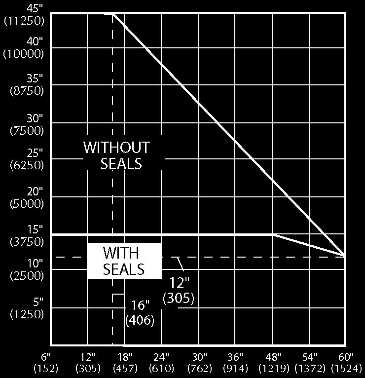
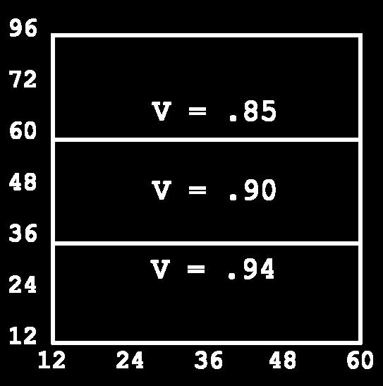
5 PERFORMANCE DATA FOR VC-1 AND VC- VOLUME CONTROL DAMPERS Damper Height in. and (mm) 19 () () () (19) (0) 0 (1) (19) LEAKAGE IN SCFM SCFM at 1 in.wg (0 Pa) WITHOUT SEALS WITH SEALS* [*] With vinyl blade edge seals and stainless steel jamb seals. To convert SCFM Leakage Values to m /s: Multiply SCFM x.000 Leakage for the VC-1 & VC- with optional seals (vinyl on blade edges and stainless steel on jamb) shall not exceed.0 scfm per sq. ft. at 1 in. wg differential pressure and a temperature of 0 F with a minimum of." pounds of torque applied to the damper shaft. Data based on a " square sample tested in accordance with AMCA Standard 00, fig.. or.. Values shown in the chart above are derived from tests performed in accordance with AMCA Standard 00 and are stated in scfm at 1 in. wg. For leakage values at greater pressures, use the conversion factors in the table below. Pressure Drop in. wg and (Pa) PRESSURE DROP Face Velocity fpm and (m/s) Tested per AMCA Standard 00, fig.. Size tested " x " TORQUE DATA Torque values are given in in.-lbs. and (Nm) FACE VELOCITY TORQUE PRESSURE TORQUE SEALING TORQUE VOLUME CONTROL DAMPERS Differential Pressure in. wg (Pa) The torque required to operate a VC-1 and VC- control damper is the greatest torque value that the damper will see in operation. The table shown gives torque values for various face velocities, differential pressures, and sealing requirements. The torque required for a damper without seals is the torque due to velocity or pressure, whichever is greater. The torque required for a damper with seals is the torque due to velocity or pressure or sealing the damper, whichever is greater. MAXIMUM PANEL SIZES Multiplier (00) 1.1 (0) 1. (00).00 MAX. PANEL SIZE LINKAGE SEALS W x (19)H In-jamb With W x (19)H In-jamb Without W x (19)H On-blade With W x (19)H On-blade Without Damper Height in. and (mm) 1 () 0 () () (1) 0 (1) (1) (19) Above values based on 00 fpm ( m/s) face velocity. Use multipliers below for other face velocities. Face Velocity fpm (m/s) Above values based on differential pressure of 1 in. wg. (0 Pa). Use multipliers below for other differential pressures. Multiplier Diff. Pressure in. wg (Pa) () () () () (9) () 91 (11) 1 (1) 111 (1) 1 () () () 0 () 9 (11) (1) 1 (1) 1 (1) 1 (1) 1 (1) 1 () () (9) 9 (11) (1) (1) 1 (1) 19 (19) 1 (19) 1 (1) 0 () () 1 (9) 90 (11) 9 (1) 19 (1) 1 (1) 1 (19) 19 () 0 () () 0 (9) Above values based on the use of dual durometer vinyl seals on the blade and metallic compression seals at the jambs. Multiplier 0 (). 1 (0) ().00 (00) 00 (1). (0) 000 (1) 9.00 (00) See page for multi-panel jackshafting arrangements.


6 Rectangular In-Duct Mount MULTI-PANEL ARRANGEMENTS FOR VC-1 AND VC- VOLUME CONTROL DAMPERS (With Jackshafting Details) 1 Single panel Double panel with no interconnection. Three or more panels with no interconnection. VOLUME CONTROL DAMPERS Double panel with 1/" diameter jackshafting. Jackshafting and panels to be factory assembled. For two panel wide assemblies only. Triple panel with left and right 1/ diameter jackshafting to be factory assembled requires two actuators. Double panel assembly larger than detail or triple panels with heavy duty jackshafting. Jackshafting and panels to be factory assembled as long as the assembly does not exceed sq. ft. face area. For double or triple panels that exceed sq. ft. face area, panels and jackshafting factory assembled then disassembled after operational checks. a Construction of each ship section identical to detail. 9 Construction of each ship section identical to detail. Construction of each ship section Construction of each ship section identical to detail. Double panel to be factory assembled.
7 MULTI-PANEL ARRANGEMENTS FOR VC-1 AND VC- VOLUME CONTROL DAMPERS (With Jackshafting Details) Construction of each ship section identical to detail. Construction of each ship section identical to detail Construction of each ship section identical to detail. VOLUME CONTROL DAMPERS Construction of each ship section identical to detail. Construction of each ship section identical to detail. Construction of each ship section identical to detail. 1 1 Construction of each ship section identical to detail. Construction of each ship section identical to detail. 1. Details 1 through 1 illustrate standard panel interconnections. Customer specified actuator selection, velocities, etc. may require different panel interconnections. Typically, the drive blade will be the bottom blade on 1 and bladed dampers and the third blade up from the sill on all dampers with or more blades. Drive axle is double screwed to the drive blade.. For single and double panel wide assemblies where jackshafting is not specified, an axle kit which includes an extended axle will be supplied. An on-face drive bracket mounted on the left end of the drive blade can be supplied at no charge in lieu of the extended axle kit. Three panel and wider assemblies where jackshafting is not specified, will be supplied with the on-face drive bracket.. Length of jackshafting to be longer than required to connect end panel so customer has option of extending jackshafting for external actuator connection. One drive arm provided as standard.. Both ship sections to be supplied with heavy duty jackshafting even though two panel ship sections may fall within limitations of 1/ dia. jackshafting.. Two extended axle kits, two interconnect arms, one interconnect angle and one drive arm provided as standard.

 Polyfoam")
 are mm Product: VC-")
 F ( C) Dimensions: A and B dimensions are opening sizes.")
 undersize and can be ordered in 1 increments only ) undersize and can be ordered in 1 increments only (Min.")
 galvanized steel hat channel 1 / (11) 0 Ga. (.91) galv. steel [ (1) through 1 () dia.]. 0 Ga. (.91) galv. steel with reinforcing beads, or 1 Ga.")
![(1.) galv. steel [19 () through dia.] Blades: 0 Ga. (.91) galvanized steel, single thickness Galvanized steel, single thickness Ga.](/docs-images/81/83795072/images/8-7.jpg "(.) / (1) to dia. 0 Ga. (.91) /1 (0) to 1 () dia. 1 Ga. (1.) /19 () to dia. Axles: / (9.")
 square plated steel stub, with lanced retainers Bearings: Nylon Nylon Finish: Mill Mill Actuator: / (9.")
8 Rectangular In-Duct Mount VC- and VC-9 Galvanized Steel Balancing Dampers The VC- and VC-9 dampers are designed for low velocity, low pressure clean air systems. They were developed specifically for use in branch ducts to balance air flow. OPTIONS: VC- Rectangular Blade Aluminum frame and blades (with stainless steel axles and bearings) Polyfoam frame stops 0 and 1 stainless steel construction VC- Section View VC-9 Round Blade VC-9 Section View VOLUME CONTROL DAMPERS STANDARD SPECIFICATIONS FOR VC- AND VC-9 Inches are shown, numbers in ( ) are mm Product: VC- VC-9 Max. Face Velocity: 0 fpm ( m/s) 0 fpm ( m/s) Max. Diff. Pressure: 1 in. wg (0 Pa) 1 in. wg (0 Pa) Max. Temperature: F ( C) F ( C) Dimensions: A and B dimensions are opening sizes. A diameter dimension is opening size. Damper will be fabricated 1 / (.) undersize and can be ordered in 1 increments only A diameter dimension is opening size. Damper will be fabricated 1 / (.) undersize and can be ordered in 1 increments only (Min. Panel Size): (1)W x (1)H Min. Dia.: (1) (Max. Panel Size): W x H Max. Dia.: Frame: 1 / (.9) x / (1.9) x 1 Ga. (1.) galvanized steel hat channel 1 / (11) 0 Ga. (.91) galv. steel [ (1) through 1 () dia.]. 0 Ga. (.91) galv. steel with reinforcing beads, or 1 Ga. (1.) galv. steel [19 () through dia.] Blades: 0 Ga. (.91) galvanized steel, single thickness Galvanized steel, single thickness Ga. (.) / (1) to dia. 0 Ga. (.91) /1 (0) to 1 () dia. 1 Ga. (1.) /19 () to dia. Axles: / (9.) square plated steel stub, with lanced retainers / (9.) square plated steel stub, with lanced retainers Bearings: Nylon Nylon Finish: Mill Mill Actuator: / (9.) square manual locking quadrant. Shipped loose for field mounting / (9.) square manual locking quadrant. Shipped loose for field mounting


 are mm Max. Face Velocity: Max. Differential Pressure: Max.")
 00 F (9 C); without seals F ( C); with seals A and B dimensions are opening sizes. Dampers will be fabricated 1 / \" (.) undersize W x 9 () H (without seals) W x (19) H (with seals) (1.")
 galv., 9 1 / (1) max. width; (1) min. width 1 / \" (1.")
9 Rectangular In-Duct Mount VC-0 and VC-1 Galvanized Steel Dampers These dampers are used as an alternate selection to Models VC-1 and VC- when heavier gauges, larger axles or different alloys are required. Unlike roll formed products, blade widths can vary maximizing free area and lowering pressure drop. These models allow flexibility to change frame styles and depths for different mounting applications. Corrosive or spark resistant applications are common uses for these models. OPTIONS: Stainless steel frame and blades Aluminum frame and blades Stainless steel axles and linkage Bearings: OIB, stainless steel, Teflon sleeve, press fit ball Seals: vinyl blade, metallic compression jamb Mounting holes VC-0 Parallel Blade Through shaft drive axle only VC-1 Opposed Blade Bolts not supplied VOLUME CONTROL DAMPERS Factory assembled mullion when jackshafting is not used. Field assembled mullion VC-0 Parallel blade VC-1 Opposed blade STANDARD SPECIFICATIONS FOR VC-0 AND VC-1 Inches are shown, numbers in ( ) are mm Max. Face Velocity: Max. Differential Pressure: Max. Temperature: Dimensions: Max. Panel Size: Min. Panel Size: Frame: Blades: Axles: Bearings: Linkage: Stops: Finish: Actuator: 000 fpm (1 m/s) in. wg (00 Pa) 00 F (9 C); without seals F ( C); with seals A and B dimensions are opening sizes. Dampers will be fabricated 1 / " (.) undersize W x 9 () H (without seals) W x (19) H (with seals) (1.) W x (0.) H (Parallel) (1.) W x (0.) H (Opposed) 1 / (.9) x / (1.9) x 1 Ga. (1.) galv. steel hat channel. Dampers 9 sq. ft. and smaller have a 1 / (19.) x / (1.9) x 1 Ga. (1.) galvanized steel hat channel over 9 sq. ft. under 1 high will be fabricated with a Ga. galv. steel plate at head and sill 1 Ga. (1.) galv., 9 1 / (1) max. width; (1) min. width 1 / " (1.) plated steel stub Heavy-duty self-lubricating nylon (00 F) Plated steel brackets, brass barrels and / 1 Dia. plated steel rod. Dampers with seals have double linkage on panels over wide Galvanized steel angle Mill with touch-ups on welds An extendable shaft is standard 9
10 Rectangular In-Duct Mount PERFORMANCE DATA FOR VC-0 AND VC-1 VOLUME CONTROL DAMPERS JACKSHAFTING Jackshafting on dampers with or without seals is required if a single actuator is used on multi-panel dampers that are larger than those shown below. AWV provides a substantial jackshafting arrangement to eliminate the twist found in many light duty designs. MAXIMUM FACTORY ASSEMBLED SIZES " (19) 9" () " " Damper Height " (19) " Damper Height " " 9" () Damper Width 1" () 9" () Damper Width 1" () WITH SEALS (Not requiring jackshafting) WITHOUT SEALS (Not requiring jackshafting) VOLUME CONTROL DAMPERS Pressure Drop in. wg and (Pa) VC-0 Face Velocity fpm and (m/s) Tested per AMCA Standard 00, fig.. Size tested " x " PRESSURE DROP Pressure Drop in. wg and (Pa) VC-1 Face Velocity fpm and (m/s) Tested per AMCA Standard 00, fig.. Size tested " x "
11 PERFORMANCE DATA FOR VC-0 AND VC-1 VOLUME CONTROL DAMPERS Quantities are derived from tests performed in accordance with AMCA 00; quantities shown are at 1 in. wg differential pressure. For in. wg, multiply by 1.. To convert SCFM Leakage Values to m/s: Multiply SCFM x.000 Damper Height in. and (mm) 0 (1) (19) (1) 9 () LEAKAGE IN SCFM WITHOUT SEALS WITH SEALS VOLUME CONTROL DAMPERS TORQUE DATA Torque values are given in in.-lbs. and (Nm) BLADE QUANTITY BLADE WIDTH FACE VELOCITY TORQUE DAMPER WIDTH IN. AND (MM) PRESSURE TORQUE DAMPER WIDTH IN. AND (MM) SEALING TORQUE DAMPER WIDTH IN. AND (MM) Damper Height in. and (mm) 0 (1) (19) () 1 () () (9) () () () 0 () (1) 11 (1) () () (1) 1 (1) 1 (1) 0 () 0 () (1) 1 (1) 1 (19) 19 () (1) () 1 () 9 () () 1 () () Above values based on 00 fpm ( m/s) face velocity. Use multipliers below for other face velocities. Above values based on differential pressure of 1 in. wg. (0 Pa). Use multipliers below for other differential pressures. Above values based on the use of dual durometer vinyl seals on the blade and metallic compression seals at the jambs. The torque required to operate a VC-0 control damper is the greatest torque value that the damper will see in operation. The tables shown give torque values for various face velocities, differential pressures, and sealing requirements. The torque required for a damper without seals is the torque due to velocity or pressure, whichever is greater. The torque required for a damper with seals is the torque due to velocity or pressure or sealing the damper, whichever is greater. Face Velocity fpm (m/s) Multiplier Diff. Pressure in. wg (Pa) Multiplier 0 (). 1 (0) () (00) 00 (1). 000 (1)
 and velocities up to,000 fpm (0 m/s) at its maximum panel width.")

 are mm")
 in. wg (0 Pa) F ( C) A and B dimensions are opening sizes.")
 Two sections high or two sections wide 1 / (10) x / (.) x 1 Ga. (1.) galvanized steel hat channel Double skin galvanized steel construction with single-lock seam, airfoil shaped stronger than 1 Ga.")
12 Rectangular In-Duct Mount VC- and VC- Galvanized Steel Dampers These dampers are designed for in duct mounting. The airfoil roll formed blades and roll formed frame are capable of withstanding differential pressures of in. wg (0 Pa) and velocities up to,000 fpm (0 m/s) at its maximum panel width. For higher pressures and velocities, refer to limitation table. OPTIONS: VC- Parallel Blade Bearings: OIB, stainless steel Actuators: manual, electric and pneumatic actuators mounted either side, and inside or outside the air stream Factory assembled jackshafting up to sq. ft. On-blade drive bracket for internal operation Mounting holes VC- Opposed Blade VC- Parallel blade VC- Opposed blade STANDARD SPECIFICATIONS FOR VC- AND VC- Inches are shown, numbers in ( ) are mm VOLUME CONTROL DAMPERS 1 Max. Face Velocity: Max. Differential Pressure: Max. Temperature: Dimensions: Max. Panel Size: Min. Panel Size: Maximum Size: Max. Configuration Per Actuator: Frame: Blades: Seals: Axles: Bearings: Linkage: Stops: Finish: Actuator: 000 fpm (0 m/s) in. wg (0 Pa) F ( C) A and B dimensions are opening sizes. Dampers will be fabricated 1 / (.) undersize W x 0 (1) H (0) W x (0) H (Parallel) (0) W x H (Opposed) Single Section: W x 0 (1) H. Multiple Section: 9 () W x 0 (1) H (W x 1H) or W x (0) H. (1W x H) Two sections high or two sections wide 1 / (10) x / (.) x 1 Ga. (1.) galvanized steel hat channel Double skin galvanized steel construction with single-lock seam, airfoil shaped stronger than 1 Ga. (1.9) equivalent, 1 / (19) wide including edge seals) by a minimum of 1 / (1.) thick at the center. Depending upon the damper height, a variable width blade may be required which will extend to a maximum of 1 / () from either the front or back of the damper. If the exact dimension of this variable blade is critical, contact AWV. Dual durometer vinyl (high impact PVC) on blade edges and metallic compression type at jambs 1 / (1.) square plated steel stub, mechanically locked to the blades Non-metallic nylon In-jamb type, plated steel angle and crank plates, and stainless steel pivots Galvanized steel angle Mill (1) extended shaft. Dampers more than one panel wide or high, and operated with one actuator, must be jackshafted
 PERFORMANCE DATA FOR VC- AND VC- VOLUME CONTROL DAMPERS LEAKAGE IN SCFM WITH SEALS 1 () 0 () () 1 1 1 1 () 9 1 1 1 1 1 1 0 0 () 1 0 0 0 1 1 0 () 1 1 9 1 0 (1) 1 0 (1) 0 0 0 0 0 0 0 Values")
13 Damper Height in. and (mm) PERFORMANCE DATA FOR VC- AND VC- VOLUME CONTROL DAMPERS LEAKAGE IN SCFM WITH SEALS 1 () 0 () () () () () (1) 1 0 (1) Values shown in the leakage chart above are derived from tests performed in accordance with AMCA Standard 00 and are stated in 1 in. wg. (0 Pa). For leakage values at greater pressures, use the conversion factors in the table below. To convert SCFM Leakage Values to m/s: Multiply SCFM x.000 Differential Pressure in. wg (Pa) Multiplier (00) 1.1 (0) 1. (00).00 Pressure Drop in. wg and (Pa) PRESSURE DROP Face Velocity fpm and (m/s) Tested per AMCA Std. 00; fig.. Size Tested " x " VOLUME CONTROL DAMPERS For pressures of in. wg and less, and where face velocities do not exceed 00 fpm, the torque values shown in the Sealing Torque table below include the maximum amount of torque required for all values. When pressures or velocities exceed these amounts, the maximum torque may exceed these values. Consult the Velocity Torque or Pressure Torque tables to determine the maximum torque in these instances. Damper Height in. and (mm) 1 0 () () TORQUE DATA Torque values are given in in.-lbs. and (Nm) FACE VELOCITY TORQUE DAMPER WIDTH IN. AND (MM) PRESSURE TORQUE DAMPER WIDTH IN. AND (MM) SEALING TORQUE DAMPER WIDTH IN. AND (MM) 1 0 () () () () () () () () 0 () 1 1 () 0 () () () () () () 1 19 () () () 1 () 1 () () () 9 () 9 (9) 0 () 9 1 () () () (9) () 1 () () 0 () () 9 (11) () () 1 () (9) 9 (11) (1) 0 () 1 () () 1 () 9 (11) 111 (1) (1) () () () () (9) 1 () 90 (11) 99 (1) (1) 11 (1) 1 (1) 0 (1) MAXIMUM DIFFERENTIAL PRESSURE AND FACE VELOCITY Damper Width Maximum System Pressure. in. wg (1 Pa). in. wg (0 Pa). in. wg (00 Pa) 1.0 in. wg (0 Pa) Maximum System Velocity 000 fpm (0 m/s) 000 fpm (0 m/s) 000 fpm ( m/s) 000 fpm (0 m/s) Above values are based on 00 fpm ( m/s) face velocity. Use multipliers below for greater velocities. 1 () () () 1 () Above values are based on in. wg (00 Pa) differential pressure. Use multipliers below for greater pressures. Face Velocity fpm (m/s) Multiplier Diff. Press. in. wg (Pa) Multiplier 0 (). (0) ().00 (00).0 00 (1). (). 000 (1) 9.00 (0).0 00 (1) (0) () 90 (11) 0 (1) 1 (1) (1) 10 (1) 11 (1) Note: Care should be taken in designing systems requiring higher pressures and higher velocities which, in turn, will elevate the operating torque of the dampers. When damper torque exceeds the design limits of extended shaft operation, (0 in. lbs. max.), the use of in-duct or jackshafted actuators is required. 1


 VC- Parallel blade Optional on-blade")
 through W; in. wg (0 Pa) above W F ( C) A and B dimensions are opening sizes. Dampers will be fabricated 1 / (.) undersize 0 (1) W x (1) H (1.")
 thick 0-T extruded aluminum hat channel / (1.) x.00 (1.) thick extruded aluminum hat channel / (9.")
14 Rectangular In-Duct Mount VC- and VC-9 Aluminum Airfoil Blade Dampers The VC- and VC-9 are designed for two position or proportional control of clean air flow in medium pressure, medium velocity systems. The VC- parallel blade unit is recommended for constant pressure drop applications such as mixing air, multi-zone, face and bypass as well as normal open/closed applications. The VC-9 opposed blade is recommended for varying pressure drop applications such as volume control. VC- Parallel Blade OPTIONS: On-blade linkage for VC- Stainless steel axles Bearings: stainless steel, OIB bearings Stainless steel on-blade linkage Silicone blade seals Special finishes Insulated frames and blades VC-9 Opposed Blade VOLUME CONTROL DAMPERS Max. Face Velocity: Max. Differential Pressure: Max. Temperature: Dimensions: Max. Panel Size: Min. Panel Size: Frame: Blades: Axles: Bearings: Linkage: Seals: Finish: Actuator: Extended Axle Detail 000 fpm (0 m/s) VC- Parallel blade Optional on-blade linkage VC-9 Opposed blade Standard in-jamb linkage STANDARD SPECIFICATIONS FOR VC- AND VC-9 Inches are shown, numbers in ( ) are mm in. wg (0 Pa) through W; in. wg (0 Pa) above W F ( C) A and B dimensions are opening sizes. Dampers will be fabricated 1 / (.) undersize 0 (1) W x (1) H (1.) W x (1.) H (Parallel) (single blade) (1.)W x 9 (.) H (Opposed) Min. height with jackshafting - (0.) 1 / (10) x.1 (.) thick 0-T extruded aluminum hat channel / (1.) x.00 (1.) thick extruded aluminum hat channel / (9.) square plated steel Nylon Plated steel bar and concealed in-jamb type arms Extruded santoprene on blade edges with stainless steel compression at jambs Mill with touch-ups on welds Extended shaft. Dampers more than one panel wide or high and operated with one actuator must be jackshafted. Factory supplied actuators are shipped loose to be mounted externally with extended shaft kit as standard. 1

 VOLUME CONTROL DAMPERS TORQUE DATA Closing Torque Applied to Extend Shaft Torque Multipliers for Pressures Greater than in. wg Damper Width Closing Torque (in-lbs/sq. ft.")
15 PERFORMANCE DATA FOR VC- AND VC-9 VOLUME CONTROL DAMPERS Performance is based on AMCA Standard 00, Figure. (in-duct mount), operating temperatures between 0ºF and ºF and a standard air density of 0. lb/ft. Actual pressure drop performance will vary based on damper size and exact installation configuration. The curves shown on the right are parallel blade results, opposed blade results are similar. Pressure Drop in. wg and (Pa) PRESSURE DROP Face Velocity fpm and (m/s) Test Figure. (in duct) VOLUME CONTROL DAMPERS TORQUE DATA Closing Torque Applied to Extend Shaft Torque Multipliers for Pressures Greater than in. wg Damper Width Closing Torque (in-lbs/sq. ft.) Damper Width Static Pressure (in. wg) 1A (1.) in. wg in. wg in. wg in. wg 1 (0.) W Maximum 1. in. wg. in. wg. in. wg. in. wg (0.) 0 W Maximum Maximum Pressure is in. wg 0 (0) Leakage VC- and VC-9 are rated for Class IA leakage as tested to AMCA Standard 11-99: Certified Ratings Programs for Air Control Devices. Class IA leakage is defined as CFM/sq. ft. of damper face area at 1 in. wg. Closing torques followed the rules described below. Leakage is based on temperature ranges from 0 density of 0. lb/ft. LEAKAGE, cfm/sqft (l/s/sqm) Pressure / Class Required Ratings 1 in. wg (0. kpa) in. wg (1.0 kpa) 1A (1.) N/A 1 (0.) (0.) (0.) 0 () 0 (0) 0 (0) AWV certifies that the model VC-/9 damper shown herein is licensed to bear the AMCA Seal. The ratings shown are based on tests and procedures performed in accordance with AMCA Publication 11 and comply with the requirements of the AMCA Certified Ratings Program. The AMCA Certified Ratings Seal applies to air performance ratings and Air Leakage ratings. 1


 are mm Max. Face Velocity: Max. Differential Pressure: Max.")
 in.")
 (1) W x / () H (single) (1), 0-T/T extruded alum. hat shaped channel,.")
16 Extruded Aluminum Thermal Break CR- and CR-9 Aluminum Airfoil Blade Damper The CR-, parallel blade and CR-9, opposed blade are designed to be used in those application where temperature transfer is not allowed in the airflow system. Damper is thermally performance tested to ASTM C-1-9. Thermally Insulated, Thermally Broken Airfoil Blades. The blades are an extruded aluminum airfoil design that minimizes turbulent airflow and reduces pressure drop across the face of the unit. The airfoil blade is insulated with high-density foam injected polyurethane. Each blade is thermally broken on the entering and leaving edges of the blade; preventing temperature transfer when the damper is in the fully closed position. CR-9 Opposed Blade Optional Reverse Frame VOLUME CONTROL DAMPERS 1 STANDARD SPECIFICATIONS FOR CR- Inches are shown, numbers in ( ) are mm Max. Face Velocity: Max. Differential Pressure: Max. Temperature: Min. Temperature: Max. Panel Size CR-: Min. Panel Size CR-: Max. Panel Size CR-9: Min. Panel Size CR-9: Frame: Optional Thermal Break Frame: Blade: Axle: Bearings: Linkage: Seals: Finish: 0 fpm (1 m/s) in. wg (19 Pa) -0 F (- C) to 00 F (9C), with thermal break frame -0 F (-0 C) to 00 F (9C), without thermal break frame 0 (1) W x (1) H, (parallel/opposed) (0) W x / () H, (single) 0 (1) W x (1) H, (parallel/opposed) (1) W x / () H (single) (1), 0-T/T extruded alum. hat shaped channel,.00 nominal,.1 optional wall thickness (1) W x 1 / () H, 0-T/T extruded alum. hat shaped channel,.00 nominal wall thickness, and two thermal breaks filled with polyurethane and debridged for thermal isolation (1) W, 0-T-/T extruded aluminum.00 nominal wall thick Airfoil profile injected with two part polyurethane (CFC) free foam and debridged for thermal isolation 1 / (1) Dia. extruded alum. pin-lock design, interlocking into blade section Double-Sealed type with celcon inner bearing riding inside polycarbonate outer bearing positively locked into frame, designed that there be no metal-to-metal or metal-to-bearing riding surfaces Concealed in jamb of heavy aluminum. Crank arm permanently locked to blade axle by two stainless steel fasteners. The crank arm contains 1 / dia. metal pivot riding in a celcon bearing. A 1 / -0 set screw with locking patch ties the / 1 dia. alum. linkage rod. The linkage of each damper is individually adjusted Extreme low temp. seal system, extruded silicone rubber blade edge seal that fits into a ribbed groove insert in blades with an extruded polycarbonate seal at jambs Mill

17 PERFORMANCE DATA FOR CR- VOLUME CONTROL DAMPERS Pressure drop ratings are based on AMCA Standard 00-D-9 using test setup figure. for damper installed with duct upstream and downstream. Static pressures are corrected to 0. Lb./Cu. Ft. air density. Pressure Drop in. wg and (Pa) PRESSURE DROP Face Area Velocity (Ft/Min) VOLUME CONTROL DAMPERS LEAKAGE IN SCFM WITH SEALS 0 (1) 1 () Damper Height in. and (mm) 0 () () Leakage ratings are based on AMCA standard 00-D-9 using test set-up Fig.. data is based on a closing torque of In-Lb./Sq.Ft. for dampers less than Sq. Ft. having a closing torque of 0 In-Lb. Damper closing torque is applied to damper operating shaft. (1) (1) (1) 11 (19) 1 0 1


 are")
 undersize Max.")
 x 1 Ga. (1.) galv. steel hat channel. Dampers with a B dimension of 1 (0) or less will have a flat Ga. (.) galvanized steel plate at head and sill Blades: 1 Ga. (1.1) galv.")
18 Rectangular In-Duct Mount VC-0 and VC-1 Galvanized Steel Dampers These dampers are used as an alternate selection to the VC- and VC- when heavier gauges, larger axles or different alloys are required. Unlike roll formed products, blade widths can vary maximizing free area and lowering pressure drop. These models allow flexibility to change frame styles and depths for different mounting applications. Corrosive or spark resistant applications are common uses for these models. OPTIONS: Bearings: stainless steel sleeve, Teflon sleeve, O.I.B., press fit ball bearings Seals: EPT blade, metallic compression jamb Stainless steel linkage and axles Mounting holes VC-0 Parallel Blade VC-1 Opposed Blade Through shaft drive axle only Bolts (Not supplied) Factory assembled mullion when jackshafting is not used. Field Assembled Mulllion VOLUME CONTROL DAMPERS 1 VC-0 Parallel Blade VC-1 Opposed Blade STANDARD SPECIFICATIONS FOR VC-0 AND VC-1 Inches are shown, numbers in ( ) are mm Max. Face Velocity: 000 fpm (1 m/s) Max. Differential Pressure: in. wg (00 Pa) Max. Temperature: 00 F ( C) without seals F ( C). with seals Dimensions: A and B dimensions are opening sizes. Dampers will be fabricated 1 / (.) undersize Max. Panel Size: W x 9 () H (without seals) W x (19) H (with seals) Min. Panel Size: (1) W x (1)H (Parallel blade VC-0) (1) W x H (Opposed blade VC-1) Frame: 1 / (10) x / (.) x 1 Ga. (1.) galv. steel hat channel. Dampers with a B dimension of 1 (0) or less will have a flat Ga. (.) galvanized steel plate at head and sill Blades: 1 Ga. (1.1) galv. steel, 9 1 / (1) max. width Axles: 1 / (1.) diameter plated steel full length through () wide. / (19) diameter plated steel full length, above () wide Bearings: Heavy-duty self-lubricating nylon Linkage: Plated steel brackets, brass barrels, and / 1 (.9) dia. plated steel rod. Dampers with seals have double linkage on panels over wide Stops: Extruded santoprene on blade edges with stainless steel compression at jambs Finish: Mill Actuator: An extended shaft is standard
19 PERFORMANCE DATA FOR VC-0 AND VC-1 VOLUME CONTROL DAMPERS Pressure Drop in. wg and (Pa) PRESSURE DROP VC-0 Face Velocity fpm and (m/s) Tested per AMCA Std. 00; fig.. Size Tested " x " Values shown in the chart on the right are derived from tests performed in accordance with AMCA Standard 00 and are stated in scfm at 1 in. wg. For leakage values at greater pressures, use the conversion factors in the small table above. Pressure Drop in. wg and (Pa) PRESSURE DROP VC-1 Face Velocity fpm and (m/s) Tested per AMCA Std. 00; fig.. Size Tested " x " LEAKAGE IN SCFM WITHOUT SEALS WITH SEALS VOLUME CONTROL DAMPERS Differential Pressure in. wg (Pa) Multiplier (00) 1.1 (0) 1. (00).00 Damper Height in. and (mm) (1) (19) (1) To convert SCFM Leakage Values to m/s: Multiply 9 () 0 11 SCFM x.000 TORQUE DATA Torque values are given in in.-lbs. and (Nm) FACE VELOCITY TORQUE PRESSURE TORQUE SEALING TORQUE Damper Height in. and (mm) 0 (1) (19) (1) 9 () () 0 () () () () () 90 (11) 111 (1) 1 (1) 9 () 1 () (1) 10 (1) 11 (0) 0 () Face Velocity fpm (m/s) () 9 (11) 1 (1) 190 () () () 9 () 11 (1) 1 (1) 1 (1) 9 () 0 (0) Multiplier The torque required to operate a VC-0 type air control damper is dependent on the largest torque value that the damper will see in actual operation. The torque tables give torque values for various face velocities, differential pressures, and sealing requirements. The torque required for a damper without seals is the largest value of torque due to velocity or pressure. The torque required for a damper with seals is the largest value of torque due to velocity, pressure or sealing the damper. Diff. Pressure in. wg (Pa) Multiplier Above values are based on 00 fpm ( m/s) face velocity. Use multipliers below for other face velocities. Above values are based on 1 in. wg (00 Pa) diff. pressure. Use multipliers to the right for other pressures. 0 (). (00) 000 () (0) 00 (1). (00) 000 (1) 9 () 19


 are mm Max.")
 -0 F (-0 C) Dimensions: A and B are inside frame dimensions,")

 x 1 1 / (.")
 Square plated.")
20 Rectangular In-Duct Mount VC-10 Galvanized Steel Damper The VC-10 is designed to be used in an air intake or exhaust shutter application. It is a heavy-duty design of the VC- standard duty damper. The primary application is in conjunction wall mounted propeller fans and power rood ventilators. Operating is by a power open spring closed motoring or manual pull chain operators. VC-10 Face View VC-10 Rear View Face View VOLUME CONTROL DAMPERS STANDARD SPECIFICATIONS FOR VC-10 Inches are shown, numbers in ( ) are mm Max. Face Velocity: 000 fpm (1 m/s) Max. Differential Pressure: in. wg (00 Pa) Max. Temperature: 1 F ( C) -0 F (-0 C) Dimensions: A and B are inside frame dimensions, (standard and reverse flange). Wall openings must be 1 larger than A dimension to allow for axle clearance, and 1 / larger than B dimension Max. Panel Size: W x 9 () H Min. Panel Size: W x H Frame: (0.) x 1 1 / (.1) flange (standard and reverse) Blades: 1 Ga. (1.) galv. steel, (1.) max. width Axles: 1 / (1.) Square plated. Steel stub, with drive through axle Bearings: Heavy-duty molded nylon Linkage: Plated steel brackets, brass barrels, and / 1 (.9) dia. rod Stops: 1 Ga. galvanized steel angle head and sill Finish: Mill with touch-ups on welds Actuator: 11 VAC motor with built in end switch Optional Reverse Frame Mullion Detail 0


 diameter through")


 diameter Through 1 ()")


21 Round In-Duct Mount Models VC-, VC--BD, VC- Galvanized Steel Dampers The VC- volume control damper is designed for all types of round duct applications such as variable air volume systems, etc. Available in sizes of " (1) diameter through 1" () diameter. VC- Stop Detail Optional Seal Detail VOLUME CONTROL DAMPERS The VC--BD Designed to be used for round in-duct applications as a gravity operated backdraft damper. Available in sizes (1) diameter Through 1 () diameter. Can be installed for vertical or horizontal airflow. Stop Detail Optional Seal Detail VC--BD The VC- comes with two opposed blades and covers a range of sizes larger than those available in the VC-. Designed for volume control and/or shut-off use in round ducts from 1" through " (11) diameter. It can also be used in applications where limitations in the depth of the space envelope precludes the use of single blade dampers. For diameters exceeding " (11), see the model VC-. Stop Detail Optional Seal Detail VC- 1

 diameter through \" diameter.")
 undersized Product: VC- VC- VC- VC- Max. Face Velocity: 000 fpm (1 m/s) 000 fpm (1 m/s) 000 fpm (1 m/s) 000 fpm (1 m/s) Max. Differential in. wg (00 Pa) in. wg (00 Pa) in. wg (00 Pa) in. wg (0 Pa) Pressure: Max.")
 x 1 / (1.) x 1 Ga. (1.9) galv. steel channel (1) x 1 / (1.) x 1 Ga. (1.9) galv. steel channel (1) x 1 / (1.) x 1 Ga. (1.9) galv. steel channel 0 Ga. (.91) galv.")
![steel, () deep [through 1 () diameter] 1 Ga. (1.1) galv. steel, () deep [over 1 () diameter] Inner frame: 1 Ga. (1.) galv. steel angle 1 Ga. (1.9) galv. steel angle Blades: 1 Ga. (1.) galv. steel 1 Ga.](/docs-images/81/83795072/images/22-6.jpg "(1.) galv. steel 1 Ga. (1.) galv. steel Double thickness galv. steel, 1 Ga. (1.9) equiv. thickness Axles: Bearings: 1 / (1.) dia.")
22 Round In-Duct Mount Models VC-, VC- Galvanized Steel Dampers Designed for two position or proportional control of low pressure, low velocity applications where a round damper is required which exceeds the maximum size limitations of the VC- or VC-. The VC- parallel blade is recommended for constant pressure drop applications such as fresh and return air dampers. The VC- opposed blade is designed for varying pressure drop applications. Available in sizes of 0 (0) diameter through 0 (10) diameter. VC- Parallel Blades Opposed Blades The VC- is designed for all types of low leakage, round duct applications. Available in sizes of " () diameter through " diameter. For diameters exceeding ", contact factory. VC- VOLUME CONTROL DAMPERS STANDARD SPECIFICATIONS FOR MODELS VC-,, AND Inches are shown, numbers in ( ) are mm Damper diameters are 1/ (.1) undersized Product: VC- VC- VC- VC- Max. Face Velocity: 000 fpm (1 m/s) 000 fpm (1 m/s) 000 fpm (1 m/s) 000 fpm (1 m/s) Max. Differential in. wg (00 Pa) in. wg (00 Pa) in. wg (00 Pa) in. wg (0 Pa) Pressure: Max. Temperature: 10 F ( C) without seals 10 F ( C) without seals 10 F ( C) without seals F ( C) F ( C) with seals F ( C) with seals F ( C) with seals Min Diameter: Max Diameter: (1) 1 () (11) 0 (10) (1) Frame: (1) x 1 / (1.) x 1 Ga. (1.9) galv. steel channel (1) x 1 / (1.) x 1 Ga. (1.9) galv. steel channel (1) x 1 / (1.) x 1 Ga. (1.9) galv. steel channel 0 Ga. (.91) galv. steel, () deep [through 1 () diameter] 1 Ga. (1.1) galv. steel, () deep [over 1 () diameter] Inner frame: 1 Ga. (1.) galv. steel angle 1 Ga. (1.9) galv. steel angle Blades: 1 Ga. (1.) galv. steel 1 Ga. (1.) galv. steel 1 Ga. (1.) galv. steel Double thickness galv. steel, 1 Ga. (1.9) equiv. thickness Axles: Bearings: 1 / (1.) dia. plated steel stub Nylon sleeve with stainless steel thrust washers 1 / (1.) dia. plated steel stub Nylon sleeve with stainless steel thrust washers 1 / (1.) dia. plated steel stub Nylon sleeve with stainless steel thrust washers 1 / (1.) dia. plated steel stub Oil impregnated bronze Seals: Optional Optional Optional Ameriprene, one piece, enclosed in a -piece blade construction Linkage: Plated steel brackets, brass barrels, and a / 1 (.9) diameter plated steel rod Plated steel brackets, brass barrels, and a / 1 (.9) diameter plated steel rod Stops: # plated sheet metal screws for the open and # plated sheet metal screws for the open and #-1 bolt with locknut at open and closed closed positions closed positions Finish: Mill Mill Mill Mill Actuator: An extendable shaft (1) beyond the frame is standard An extendable shaft (1) beyond the frame is standard An extendable shaft (1) beyond the frame is standard An extendable shaft (1) beyond the frame is standard
 PERFORMANCE DATA FOR ROUND VOLUME CONTROL DAMPERS PRESSURE DROP VC- & VC- Face Velocity fpm and (m/s) Tested per AMCA")
 PRESSURE DROP VC- Pressure in. wg and (Pa) Tested per AMCA Std. 00, fig.. Damper Dia.")
 0 0 (11) 0 () 0 0 () 0 0 0 (10) Table above depicts leakage through models VC-, VC-, VC- and VC- at 1 in.")
23 Pressure Drop in. wg and (Pa) PERFORMANCE DATA FOR ROUND VOLUME CONTROL DAMPERS PRESSURE DROP VC- & VC- Face Velocity fpm and (m/s) Tested per AMCA Std. 00; fig.. Size tested 1" dia. Pressure Drop in. wg and (Pa) PRESSURE DROP VC- Face Velocity fpm and (m/s) Tested per AMCA Std. 00; fig.. Size tested " dia. VOLUME CONTROL DAMPERS Airflow scfm and (m/s) PRESSURE DROP VC- Pressure in. wg and (Pa) Tested per AMCA Std. 00, fig.. Damper Dia. in. and (mm) LEAKAGE IN SCFM VC- VC- VC- VC- () 0.9 (1) 1.1 (0) 9 1. () () 1. 1 (0) () (0) 1.1 (0) (0) 0 0 (11) 0 () 0 0 () (10) Table above depicts leakage through models VC-, VC-, VC- and VC- at 1 in. wg differential pressure tested per AMCA Std. 00, Figure.. To convert SCFM Leakage Values to m/s: Multiply SCFM x.000


24 Rectangular Duct Flange Mount Model 00 Series - Single Thickness Blade American Warming and Ventilating's 00 Series single thickness blade volume control dampers are designed for a steady range of pressures and velocities. The performance of the parallel or opposed blade design for clean air systems allows superior performance in both constant and varying pressure drop applications. The parallel blade unit is recommended for constant pressure drop applications such as mixing air, multi-zone, face and bypass as well as normal open/closed applications. The opposed blade unit is recommended for varying pressure drop conditions such as volume control or as a blower outlet. Parallel Blade OPTIONS: Opposed Blade Axles and Linkage construction: 0 and 1 stainless steel (VC-1 & 1) Bearings: stainless steel sleeve (all units); (VC-1) stainless steel ball with cadmium plated races, (VC-1 & VC-1) Teflon sleeve Seals: vinyl blade (VC-11), EPT blade and silicone blade (VC-11, VC-1 & 1), stainless steel jamb Special flange width () max 0 and 1 stainless steel construction (VC-1 & 1) Actuator: manual quadrant and lever arm available in 0 and 1 stainless steel Mounting holes VOLUME CONTROL DAMPERS STANDARD SPECIFICATIONS FOR MODELS VC-11, VC-1 AND VC-1 Inches are shown, numbers in ( ) are mm Product: VC-11 VC-1 VC-1 Max. Face Velocity: 000 fpm (1 m/s)* 000 fpm ( m/s)* 000 fpm (0 m/s)* Max. Differential Pressure: in. wg (00 Pa) 1 in. wg ( Pa)* 0 in. wg (9 Pa)* Max. Temperature: 0 F ( C) 0 F ( C) 0 F ( C) Dimensions: A (width) and B (height) dimensions are inside damper frame. Dampers will be fabricated to exact size Max. Panel Size: W x (19) w/o seals W x (19) with seals W x 9 () w/o seals W x (19) with seals 0 (1) W x 9 () w/o seals 0 (1) W x (19) with seals Min. Panel Size: (1) W x (0) H (Parallel) (1) W x H (Opposed) (1) W x (0) H (Parallel) (1) W x H (Opposed) (1) W x (0) H (Parallel) (1) W x H (Opposed) Frame: (0) x (1) x 1 Ga. (1.9) galv. steel through (19)H; 1 Ga. (.) through 9 () (0) x (1) x 1 Ga. (.) galv. steel (0) x (1) x 1 Ga. (.) galv. steel Blades: 1 Ga. (1.) galv. steel, single thickness, (0) max. width 1 Ga. (1.9) galv. steel through wide, single thickness; 1 Ga. (.) galv. steel through wide single thickness, (0) max. width 1 Ga. (.) galv. steel, single thickness, (0) max. width Axles: 1 / (1.) sq. plated steel, stub / (19) dia. plated steel, stub 1 () dia. plated steel, stub Bearings: Oil impregnated bronze Oil impregnated bronze Oil impregnated bronze Linkage: Heavy-duty plated steel arms, stainless steel pivots and galvanized steel angle, external type Heavy-duty clamp on plated steel arms, stainless steel pivots and galvanized steel angle, external type Heavy-duty clamp on plated steel arms, stainless steel pivots and galvanized steel bar, external type Stops: Galvanized steel angle Galvanized steel angle Galvanized steel angle Finish: Mill Mill Mill Actuator: An extendable shaft (1) beyond the frame on the right is An extendable shaft (1) beyond the frame on the right is standard * Velocities standard Pressures differ based on blade length. Reference charts on pages standard and 9. An extendable shaft (1) beyond the frame on the right is
25 LEAKAGE DATA (IN SCFM) FOR MODELS VC-11, VC-1 AND VC-1 Differential Pressure in. wg (Pa) Quantities are derived from tests performed in accordance with AMCA Standard 00. The values shown in the leakage chart are stated in scfm at 1 in. wg. Use of the conversion factors above will give leakage values at greater pressures. For lower leakages, contact factory. To convert SCFM Leakage Values to m/s: Multiply SCFM x.000 (See Leakage Statement above) Multiplier (00) 1.1 (0) 1. * (00).00 * (). * (0). * (10). * See Pressure Limitations Chart on Page. Differential Pressure in. wg (Pa) Multiplier (00) 1.1 (0) 1. Damper Height in. and (mm) VC-11 WITHOUT SEALS (1 in. wg) WITH SEALS (1 in. wg) 1 () 0 () () VC-1 1 () 0 () () () () () (1) (1) (1) (19) WITHOUT SEALS (1 in. wg) WITH SEALS (1 in. wg) 1 () 0 () () 1 () 0 () () () VOLUME CONTROL DAMPERS (00).00 (). (0). * (10). * (000). 9* (0).00 * (00).1 * See Pressure Limitations Chart on Page. Damper Height in. and (mm) () () (1) (1) (1) (19) (191) (1) () () (See Leakage Statement above) VC-1 Differential Pressure in. wg (Pa) Multiplier (00) 1.1 (0) 1. (00).00 (). (0). * (10). * (000). 9* (0).00 * (00).1 11* (0). 1* (000). 1* (0).1 1* (00). 1* (0). Damper Height in. and (mm) 1 () WITHOUT SEALS (1 in. wg) WITH SEALS (1 in. wg) 0 () () (1) 0 (1) () () () (1) (1) (1) (19) (191) (1) () () () 0 () () (1) 0 (1) * See Pressure Limitations Chart on pages and 9.

26 Rectangular Duct Flange Mount Model 00 Series - Airfoil Blade Construction American Warming and Ventilating's 00 Series airfoil blade volume control dampers are designed for a variable range of pressures and velocities. The performance of the parallel or opposed blade design for clean air systems allows superior performance in both constant and varying pressure drop applications. The parallel blade unit is recommended for constant pressure drop applications such as mixing air, multi-zone, face and bypass as well as normal open/closed applications. Parallel Blade The opposed blade unit is recommended for varying pressure drop conditions such as volume control or as a blower outlet. OPTIONS: Opposed Blade 0 & 1 stainless steel construction Special flange width ( max.) Axles and linkage construction: 0 & 1 stainless steel Bearings: stainless steel ball with cadmium plated races (), stainless steel sleeve, Teflon sleeve, flanged ball, stuffing boxes Seals: EPT or silicone blade and stainless steel jamb Actuator: manual quadrant and lever arm. Also available in 0 & 1 stainless steel Mounting holes VOLUME CONTROL DAMPERS STANDARD SPECIFICATIONS FOR MODELS VC-1, AND Inches are shown, numbers in ( ) are mm VC-1 VC- VC- Max. Face Velocity: 00 fpm (1 m/s)* 000 fpm ( m/s)* 000 fpm (0 m/s)* Max. Differential Pressure: 1 in. wg ( Pa)* 0 in. wg ( Pa)* in. wg (1110 Pa)* Max. Temperature: 0 F ( C) 0 F ( C) 0 F ( C) Dimensions: A (width) and B (height) dimensions are inside damper frame. Dampers will be fabricated to exact size Max. Panel Size: W x 9 () w/o seals W x (19) with seals W x 9 () w/o seals W x (19) with seals 0 (1) W x 9 () w/o seals 0 (1) W x (19) with seals Min. Panel Size: Frame: Blades: (1) W x (0) H (Parallel) (1) W x H (Opposed) (0) x (1) x 1 Ga. (1.9) galv. steel through (19) H; 1 Ga. (.) through 9 () 1 Ga. (1.) galv. steel, airfoil shape, (0) max. width (1) W x (0) H (Parallel) (1) W x H (Opposed) (0) x (1) x 1 Ga. (.) galv. steel 1 Ga. (1.) galv. steel, airfoil shape, (0) max. width (1) W x (0) H (Parallel) (1) W x H (Opposed) (0) x (1) x 1 Ga. (.) galv. steel 1 Ga. (1.) galv. steel, airfoil shape, (0) max. width Axles: 1 / (1.) sq. plated steel, full length / (19) dia. plated steel, full length 1 () dia. plated steel, full length Bearings: Oil impregnated bronze Oil impregnated bronze Oil impregnated bronze Linkage: Heavy-duty plated steel arms, stainless steel pivots and galvanized steel angle, external type Heavy-duty clamp on plated steel arms, stainless steel pivots and galvanized steel angle, external Heavy-duty clamp on plated steel arms, stainless steel pivots and galvanized steel bar, external type type Stops: Galvanized steel angle Galvanized steel angle Galvanized steel angle Finish: Mill Mill Mill Actuator: An extendable shaft (1) beyond the frame on the right is standard An extendable shaft (1) beyond the frame on the right is standard An extendable shaft (1) beyond the frame on the right is standard * Velocities and Pressures differ based on blade length. Reference charts on pages and 9.
27 LEAKAGE DATA (IN SCFM) FOR MODELS VC-1, VC- AND VC- Differential Pressure in. wg (Pa) Multiplier (00) 1.1 (0) 1. * (00).00 * (). * (0). * (10). * See Pressure Limitations Chart on Page Quantities are derived from tests performed in accordance with AMCA Standard 00. The values shown in the leakage chart are stated in scfm at 1 in. wg. Use of the conversion factors below will give leakage values at greater pressures. For lower leakages, contact factory. To convert SCFM Leakage Values to m/s: Multiply SCFM x.000 (See Leakage Statement above) Differential Pressure in. wg (Pa) Multiplier (00) 1.1 (0) 1. (00).00 (). (0). (10). (000). 9* (0).00 * (00).1 Damper Height in. and (mm) Damper Height in. and (mm) WITHOUT SEALS (1 in. wg) WITH SEALS (1 in. wg) 1 () 0 () () VC- 1 () 0 () () () () () (1) (1) (1) (19) (191) (1) () () WITHOUT SEALS (1 in. wg) WITH SEALS (1 in. wg) 1 () 0 () VC-1 () 1 () 0 () () () () () (1) (1) (1) (19) (191) VOLUME CONTROL DAMPERS * See Pressure Limitations Chart on Page (1) () (See Leakage Statement above) Differential Pressure in. wg (Pa) Multiplier (00) 1.1 (0) 1. (00).00 (). (0). (10). (000). 9 (0).00 (00).1 11 (0). 1 (000). 1* (0).1 1* (00). 1* (0). Damper Height in. and (mm) 9 () () VC- WITHOUT SEALS (1 in. wg) WITH SEALS (1 in. wg) 0 () () (1) 0 (1) () () () (1) (1) (1) (19) (191) (1) () () () 0 () () (1) 0 (1) * See Pressure Limitations Chart on pages and 9.
28 Rectangular Duct Flange Mount VELOCITY LIMITATIONS FOR 00 SERIES (SINGLE THICKNESS AND AIRFOIL BLADE DESIGN) The velocity restrictions shown below are based on the design limits of the extended shaft. In-duct actuators, jackshafting or another model is required if velocities exceed the values shown. SINGLE THICKNESS BLADE DESIGN VC-11 VC-1 VC-1 Damper Height in. and (mm) Damper Height in. and (mm) Damper Height in. and (mm) VOLUME CONTROL DAMPERS Damper Height in. and (mm) VC-1 Damper Height in. and (mm) AIRFOIL BLADE DESIGN VC- Damper Height in. and (mm) VC-
 The pressure")


29 PRESSURE LIMITATIONS FOR 00 SERIES (SINGLE THICKNESS AND AIRFOIL BLADE DESIGN) The pressure ratings shown below are based on the design limits of the extended shaft or blade deflection. Another model should be selected if pressures exceed the values shown. Differential Pressure in. wg and (Pa) VC-11 SINGLE THICKNESS BLADE DESIGN Differential Pressure in. wg and (Pa) VC-1 Differential Pressure in. wg and (Pa) VC-1 VOLUME CONTROL DAMPERS AIRFOIL BLADE DESIGN VC-1 VC- VC- Differential Pressure in. wg and (Pa) Differential Pressure in. wg and (Pa) Differential Pressure in. wg and (Pa) 9
30 Rectangular Duct Flange Mount TORQUE TABLES FOR 00 SERIES The torque required to operate the VC-00 Series Volume Control Dampers is the greatest torque value that the damper will see in operation. The condensed tables shown give torque values for various face velocities, differential pressures and sealing requirements. The torque required for a damper is the torque due to velocity or pressure or sealing the damper, whichever is greater. In either case, 0 in.-lbs. (. Nm) should be the minimum torque selected. Also, safety factors should be used when using these values to size an actuator. Model VC-11 (Single Thickness Blade ) 0 in.-lbs. (. Nm) FACE VELOCITY TORQUE PRESSURE TORQUE SEALING TORQUE Damper Width in. and (mm) Damper Height in. and (mm) 0 (1) 1 (.11) (.9) (.) (.) (.) 1 (.11) (.) (.91) (1.1) 11 (1.) (.) (.91) (1.1) 1 (1.) 1 (1.1) (.9) 9 (1.0) 1 (1.) 19 (.1) (.9) 1 (.11) (.9) (.) (.) (.) (.) (.) (.91) 9 (1.0) 11 (1.) (.9) (.91) (1.1) 1 (1.) 1 (1.1) (.) 9 (1.0) 1 (1.) 1 (.0) 1 (.) (.9) (.1) (.0) (9.) 9 (.) (.) (.1) (.) 9 (11.0) 111 (1.9) 9 (.1) (.0) (9.0) 11 (1.) 1 (1.0) (19) (.90) 1 (1.) 1 (.) (.1) (.90) 1 (1.) 1 (.) (.0) (1.1) 10 (1.) 11 (1.) VOLUME CONTROL DAMPERS 0 Face Velocity fpm (m/s) Multiplier Damper Height in. and (mm) Diff. Pressure in. wg (Pa) 0 (1) (19) (1) 9 () FACE VELOCITY TORQUE (.) (.9) (.) (.) (.91) (.90) 9 (1.0) (1.1) Multiplier 0 (). (00) 000 ().00 (0) 00 (1). (00) 000 (1) 9.00 () 00 (1) 1.1 (0) (10) (.) (.) (.90) (1.1) 1 (1.) 1 (1.1) 1 (1.9) 0 (.) Model VC-1 (Airfoil Blade) 0 in.-lbs. (. Nm) (.) (.91) 1 (1.) 1 (1.) 19 (.1) (.1) (.9) 0 (.9) VC-11 (.91) (1.1) 1 (1.1) 19 (.1) (.) 1 (.0) (.) 0 (.) VC-1 TORQUE VALUES ARE GIVEN IN in.-lbs. (Nm) The Velocity Torque values shown are based on 00 fpm ( m/s) face velocity. Use the multipliers at left for greater velocities. The Pressure Torque values shown are based on 1 in. wg (0 Pa) differential pressure. Use the multipliers at right for greater pressures. PRESSURE TORQUE (.) (.9) (.) (.) (.90) (1.1) 11 (1.) 1 (1.) (.) (.) (1.1) 1 (1.) 1 (1.1) 0 (.) (.9) (.9) (.) 9 (1.0) 1 (1.0) 1 (.0) (.1) 0 (.9) (.) 9 (.1) (.90) 1 (1.) 0 (.) (.1) (.) 0 (.).9) (.) (.) (.99) 0 (9.0) 99 (11.19) 1 (1.1) 1 (1.1) SEALING TORQUE (.) 9.) 1 (1.90) 19 (1.) 190 (1.) 1 (.) (.0) 111 (1.) 1 (1.) 00 (.0) (. (.0) 99 (11.19) 10 (1.) 09 (.) 0 (.) 0 (.1) 9 (.9)
31 Please note, care should be taken in designing systems requiring higher pressures and velocities which, in turn, will elevate the operating torque of the dampers. The shaded areas in the charts depict dampers that may exceed the design limits of extended shaft operation. The maximum torques for each model is shown in parenthesis next to the model number. When this value is exceeded, the use of in-duct or jackshafted actuators is required. TORQUE TABLES FOR 00 SERIES Damper Height in. and (mm) 0 (1) (19) (1) 9 () Model VC-1 & VC- (Single Thickness Blade) (Airfoil Blade) in. -lbs. (.9 Nm) FACE VELOCITY TORQUE (.) (.9) (.) (.) (.91) (.90) 9 (1.0) (1.1) (.) (.) (.90) (1.1) 1 (1.) 1 (1.1) 1 (1.9) 0 (.) (.) (.91) 1 (1.) 1 (1.) 19 (.1) (.1) (.9) 0 (.9) (.91) (1.1) 1 (1.1) 19 (.1) (.) 1 (.0) (.) 0 (.) PRESSURE TORQUE (.) (.9) (.) (.) (.90) (1.1) 11 (1.) 1 (1.) Face Velocity fpm (m/s) (.) (.) (1.1) 1 (1.) 1 (1.1) 0 (.) (.9) (.9) (.) 9 (1.0) 1 (1.0) 1 (.0) (.1) 0 (.9) (.) 9 (.1) Multiplier (.90) 1 (1.) 0 (.) (.1) (.) 0 (.) (.9) (.) (.) (.99) 0 (9.0) 99 (11.19) 1 (1.1) 1 (1.1) Diff. Pressure in. wg (Pa) SEALING TORQUE (.) (9.) 1 (1.90) 19 (1.9) 190 (1.) 1 (.) Multiplier (.0) 111 (1.) 1 (1.) 00 (.0) (.) (.0) 99 (11.19) 10 (1.) 09 (. 0 (.) 0 (.1) 9 (.9) VOLUME CONTROL DAMPERS TORQUE VALUES ARE GIVEN IN in.-lbs. (Nm) The Velocity Torque values shown are based on 00 fpm ( m/s) face velocity. Use the multipliers at right for greater velocities. The Pressure Torque values shown are based on 1 in. wg (0 Pa) differential pressure. Use the multipliers at left for greater pressures. 0 (). (00) 00 (1). (00) 00 (1) 1. (0) 00 () 0. (000) 00 () 0. (00) VC-1/VC- VC-1/VC- 1 (000) 1 1 (00) 1 FACE VELOCITY TORQUE Model VC-1 & VC- (Single Thickness Blade) (Airfoil Blade) 1,00 in. -lbs. (1.9 Nm) PRESSURE TORQUE Damper Width in. and (mm) SEALING TORQUE 0 (1) 0 (1) 0 (1) Damper Height in. and (mm) 0 (1) (19) (.) (.9) (.) (.) (.91) (.90) (.) (.) (.90) (1.1) 1 (1.) 1 (1.1) (.) (.91) 1 (1.) 1 (1.) 19 (.1) (.1) (.91) (1.1) 1 (1.1) 19 (.1) (.) 1 (.0) (.90) 1 (1.) 0 (.) (.1) 1 (.0) 9 (.1) (.) (.9) (.) (.) (.90) (1.1) (.) (.) (1.1) 1 (1.) 1 (1.1) 0 (.) (.) 9 (1.0) 1 (1.0) 1 (.0) (.1) 0 (.9) (.90) 1 (1.) 0 (.) (.1) (.) 0 (.) (1.1) 1 (1.0) (.) 0 (.9) 0 (.) 0 (.) (.) (.99) 0 (9.0) 99 (11.19) 1 (1.1) 1 (1.1) (.) (9.) 1 (1.90) 19 (1.) 190 (1.) 1 (.) (.0) 111 (1.) 1 (1.) 00 (.0) (.) (.0) 99 (11.19) 10 (1.) 09 (.) 0 (.) 0 (.1) 9 (.9) (1.) 1 (1.9) (.) 00 (.90) (.9) (.) (1) 9 (1.0) 1 (1.9) (.9) (.) (.) 11 (1.) (.9) (.) (.9) (.) 9 () (1.1) 0 (.) 0 (.9) 0 (.) 0 (.) 1 (1.) (.9) 9 (.1) (.) (.) 1

 max 0 and 1 stainless steel construction Actuator: manual quadrant and lever arm")
32 RECTANGULAR DUCT FLANGE MOUNT Model FO Series - Single Thickness Blade This special damper series was designed to be mounted on the outlet of a Centrifugal Fan application. It offers the options required to meet all of the performance needs of a fan outlet damper. Can be used in new, replacement, or OEM applications. OPTIONS: Axles and Linkage construction: 0 and 1 stainless steel (FO-1 & 1) Bearings: stainless steel sleeve (all units); (FO-1) stainless steel ball with cadmium plated races, (FO-1 & FO-1) Teflon sleeve, flanged ball bearings Seals: EPT blade and silicone blade, stainless steel jamb Special flange width () max 0 and 1 stainless steel construction Actuator: manual quadrant and lever arm available in 0 and 1 stainless steel Mounting holes Parallel Blade Opposed Blade Parallel Blades Opposed Blades STANDARD SPECIFICATIONS FOR MODELS FO-11, FO-1 AND FO-1 Inches are shown, numbers in ( ) are mm FO-11 FO-1 FO-1 Max. Face Velocity: 000 fpm ( m/s) 000 fpm (0 m/s) 000 fpm (0 m/s)a Max. Differential Pressure: in. wg ( Pa) 0 in. wg (0 Pa) 0 in. wg (990 Pa) FAN OUTLET CONTROL Max. Temperature: 00 F ( C) 00 F ( C) 00 F ( C) Dimensions: A (width) and B (height) dimensions are inside damper frame. Dampers will be fabricated to exact size Max. Panel Size: W x (19) W x () 0 (1) W x 9 () Min. Panel Size: (1) W x (1) H (Parallel) (1) W x () H (Opposed) (1) W x (1) H (Parallel) (1) W x () H (Opposed) (1) W x (1) H (Parallel) (1) W x () H (Opposed) Frame: () x (1) x 1 Ga. (.) carbon steel Blades: 1 Ga. (1.9) carbon steel, single thickness, () max. width () x (1) x 1 Ga. (.) carbon steel 1 Ga. (.) carbon steel, single thickness, () max. width () x (1) x 1 Ga. (.) carbon steel (through (19) H) () x 1 / () x Ga. carbon steel (through 9 () H) 1 Ga. (.) carbon steel, single thickness, () max. width (through W) Ga. carbon steel (through 0 W) Axles: 1 / (1.) dia. steel, stub / (19) dia. steel, stub 1 () dia. steel, stub Bearings: Oil impregnated bronze (to 00 F) Oil impregnated bronze (to 00 F) Oil impregnated bronze (to 00 F) with stainless steel thrust washers with stainless steel thrust washers with stainless steel thrust washers Linkage: Heavy-duty plated steel arms, stainless steel pivots and galvanized steel angle, external type Heavy-duty clamp on plated steel arms, stainless steel pivots and galvanized steel angle, external type Heavy-duty clamp on plated steel arms, stainless steel pivots and galvanized steel bar, external type Stops: Carbon steel angle Carbon steel angle Carbon steel angle Finish: One coat of AWV industrial shop One coat of AWV industrial shop One coat of AWV industrial shop primer primer primer Actuator: An extendable shaft (1) beyond the frame on the right is standard An extendable shaft (1) beyond the frame on the right is standard An extendable shaft (1) beyond the frame on the right is standard
33 Pressure (in. wg.) LIMITATIONS TABLES FOR FO SERIES - SINGLE THICKNESS BLADE Damper Width (in.) Pressure Limitations Damper Height (in.) Model FO-11 Damper Width (in.) Velocity Limitations Damper Height (in.) Damper Width (in.) Stuffing Box Limitations FAN OUTLET CONTROL Model FO-1 Pressure (in. wg.) Model FO-1 Pressure (in. wg.) Damper Height (in.) Damper Height (in.) Damper Height (in.) Damper Height (in.) Damper Width (in.) Pressure Limitations Damper Width (in.) Velocity Limitations Damper Width (in.) Stuffing Box Limitations Damper Width (in.) Pressure Limitations Damper Width (in.) Velocity Limitations Damper Width (in.) Stuffing Box Limitations
34 RECTANGULAR DUCT FLANGE MOUNT Model FO Series - Airfoil Blade Construction This special damper series was designed to be mounted on the outlet of a Centrifugal Fan application. It offers the options required to meet all of the performance needs of a fan outlet damper. Can be used in new, replacement, or OEM applications. OPTIONS: 0 & 1 stainless steel construction Special flange width ( max.) Axles and linkage construction: 0 & 1 stainless steel Bearings: stainless steel ball with cadmium plated races (), stainless steel sleeve, Teflon sleeve, flanged ball, stuffing boxes Seals: EPT or silicone blade and stainless steel jamb Actuator: manual quadrant and lever arm. Also available in 0 & 1 stainless steel Mounting holes Parallel Blade Opposed Blade STANDARD SPECIFICATIONS FOR MODEL FO SERIES Inches are shown, numbers in ( ) are mm Product: FO-1 FO- FO- Max. Face Velocity: 000 fpm ( m/s) 000 fpm (0 m/s) 000 fpm (0 m/s) Max. Differential Pressure: in. wg ( Pa) 0 in. wg (0 Pa) 0 in. wg (990 Pa) FAN OUTLET CONTROL Max. Temperature: 00 F ( C) 00 F ( C) 00 F ( C) Dimensions: A (width) and B (height) dimensions are inside damper frame. Dampers will be fabricated to exact size Max. Panel Size: W x (19) W x (1) 0 (1) W x 9 () Min. Panel Size: (1) W x (1) H (Parallel) (1) W x () H (Opposed) Frame: () x (1) x 1 Ga. (.) carbon steel (1) W x (1) H (Parallel) (1) W x () H (Opposed) () x (1) x 1 Ga. (.) carbon steel (1) W x (1) H (Parallel) (1) W x () H (Opposed) () x (1) x 1 Ga. (.) carbon steel (through (19) H) () x 1 / () x Ga. carbon steel (through 9 ()H) 1 Ga. (1.9) carbon steel, airfoil shape, () max. width Blades: 1 Ga. (1.9) carbon steel, single thickness, () max. width 1 Ga. (1.9) carbon steel, airfoil shape, () max. width Axles: 1 / (1.) dia. steel, full length / (19) dia. steel, full length 1 () dia. steel, full length Bearings: Oil impregnated bronze (to 00 F) Oil impregnated bronze (to 00 F) Oil impregnated bronze (to 00 F) with stainless steel thrust washers with stainless steel thrust washers with stainless steel thrust washers Linkage: Heavy-duty clamp on plated steel arms, stainless steel pivots and galvanized steel bar, external type Heavy-duty clamp on plated steel arms, stainless steel pivots and galvanized steel bar, external type Heavy-duty clamp on plated steel arms, stainless steel pivots and galvanized steel bar, external type Stops: Carbon steel angle Carbon steel angle Carbon steel angle Finish: One coat of AWV industrial shop One coat of AWV industrial shop One coat of AWV industrial shop primer primer primer Actuator: An extendable shaft (1) beyond the frame on the right is standard An extendable shaft (1) beyond the frame on the right is standard An extendable shaft (1) beyond the frame on the right is standard
 LIMITATIONS TABLES FOR FO SERIES -")

 Model FO-1 Damper ) Velocity")
 Damper ) Stuffing Box Limitations")
 Damper Height (in.")
 ) Damper ) Pressure Limitations")
 Stuffing Box Limitations Damper )")

35 Pressure (in. wg.) LIMITATIONS TABLES FOR FO SERIES - AIRFOIL BLADE CONSTRUCTION Damper Width (in.) Pressure Limitations Damper Height (in.) Model FO-1 Damper Width (in.) Velocity Limitations Damper Height (in.) Damper Width (in.) Stuffing Box Limitations FAN OUTLET CONTROL Model FO- Model FO- Pressure (in. wg.) Damper Height (in.) Damper Height (in.) Pressure (in. wg.) Damper Height (in.) Damper Height (in.) Damper Width (in.) Pressure Limitations Damper Width (in.) Velocity Limitations Damper Width (in.) Stuffing Box Limitations Damper Width (in.) Pressure Limitations Damper Width (in.) Velocity Limitations Damper Width (in.) Stuffing Box Limitations
36 WAY and WAY Models DF-/DF-F and DF-/DF-F American Warming and Ventilating manufactures a variety of -way and -way diffusers. These units are typically mounted to the end of a duct in manufacturing plants to disperse air in multiple directions via individually adjustable single thickness or airfoil blades. NOTE: A wide and B high designate the opening into which the diffuser must fit. Diffuser frames are manufactured a nominal 1 () undersize to permit clearance for the axle tips. This allows for a nominal usable flange width of 11/ (). For -way diffusers, the A dimension is always parallel to the blades. If vertical blades are required, specify B as the width and A as the height. For -way diffusers, the A dimension is always parallel to the horizontal blades. If vertical blades are required on the flange side, specify B as the width and A as the height. FACTORY ASSEMBLED MULLIONS DF- DF- DF-F DF-F -way -way DF- DF-F DF- -way -way DF-F STANDARD SPECIFICATIONS FOR MODELS DF-, DF-F, DF-, AND DF-F Inches are shown, numbers in ( ) are mm Product: DF- DF-F DF- DF-F Max. Face Velocity: 000 fpm (1 m/s) 000 fpm (1 m/s) 000 fpm ( m/s) 000 fpm ( m/s) Max. Panel Size: 0 () x 9 () A Dim. 0 () x 9 () 0 () x 9 () A Dim. 0 () x 9 () Frame: Mullion: (1) x (1) x 1 Ga. (1.) galv. steel through 1 () sq. 1 Ga. (1.9) above 1 () sq. 1 1 / () x 1 () x 1 Ga. (1.9) galv. steel channel through 0 (1) H; B Dim. 9 () x 0 () / (9) x (1) x 1 Ga. (1.) galv. steel through 1 () sq. 1 Ga. (1.9) above 1 () sq. 1 1 / () x 1 () x 1 Ga. (1.9) galv. steel channel through 0 (1) H; () x (1) x 1 Ga. (1.) galv. steel through 1 () sq. 1 Ga. (1.9) above 1 () sq. 1 1 / () x 1 () x 1 Ga. (1.9) galv. steel channel through (190) H; B Dim. 9 () x 0 () (1) x (1) x 1 Ga. (1.) galv. steel through 1 () sq. 1 Ga. (1.9) above 1 () sq. 1 1 / () x 1 () x 1 Ga. (1.9) galv. steel channel through (190) H; DIFFUSERS Blades: Axles: 1 1 / () x 1 1 / () x Ga. (.) galv. steel channel above 0 (1) H 0 Ga. (.91) galv. steel, airfoil, (1) width, held in place with a friction device. Each blade is individually adjustable. / 1 (.9) dia. plated steel full length 1 1 / () x 1 1 / () x Ga. (.) galv. steel channel above 0 (1) H Two 0 Ga. (.91) galv. steel, airfoil, (1) width, held in place with a friction device. Each blade is individually adjustable. / 1 (.9) dia. plated steel full length 1 1 / () x 1 1 / () x Ga. (.) galv. steel channel above 0 (1) H 0 Ga. (.91) galv. steel, single thickness, () width, held in place with a friction device. Each blade is individually adjustable. / 1 (.9) dia. plated steel stub Finish: Mill Mill Mill Mill 1 1 / () x 1 1 / () x Ga. (.) galv. steel channel above 0 (1) H Two 0 Ga. (.91) galv. steel, airfoil, () width, held in place with a friction device. Each blade is individually adjustable. / 1 (.9) dia. plated steel stub


 Frame: (1.) x / (19.1) 1 Ga. carbon steel channel Blades: 1 Ga.")
37 Heavy-Duty Radial Model DF- American Warming and Ventilating manufactures a radial diffuser for air conditioning systems in large industrial areas. Proven effective by thousands of installations in automotive plants, the radial diffuser offers a variety of air deflection patterns. Individually adjustable air deflectors allow an infinite number of air patterns and areas of coverage. The differing air pattern deflectors have minimal effect on scfm delivered or static pressure requirements. DIFFUSERS End View DF- Airflow STANDARD SPECIFICATIONS FOR DF- Inches are shown, numbers in ( ) are mm Max. Face Velocity: 000 fpm (1 m/s) Max. Panel Size: A Dimension is (.) Min. Panel Size: B Dimension is 1 (0.) Frame: (1.) x / (19.1) 1 Ga. carbon steel channel Blades: 1 Ga. carbon steel single thickness secured to axle with two hinge pads, one of those with a set screw Axles: 1 / (1.) Diameter plated or HRS steel stubs on each end Center Disk: 1 Ga. x (1.) Dia. carbon steel, located on flow entering side Disk Support: Ga. x 1 / (1.) steel welded to frame and disk Straps: 1 Ga. 1 1 / (.1) x 1 Lg. carbon steel Finish: One coat of standard shop primer

 dia.")
 are mm INDUSTRIAL ROUND DAMPERS Product: VC-1 VC- Max. Face Velocity: 900 fpm (0 m/s) fpm ( m/s) Max.")
 x 1 1 / () x 1 Ga. (.) rolled steel channel through () dia. () x (1) x Ga. (.). rolled steel channel, 1 / 1 () through 0 (1) dia. (0) x 1 1 / () x Ga. (.) rolled steel channel through () dia. () x (1) x Ga. (.) rolled steel channel, 1 / 1 () through 0 (1) dia.")
38 ROUND DUCT FLANGE MOUNT Model VC-0 Series - Industrial Round Dampers The VC-0 Series is designed for all types of round duct applications ranging from (1) diameter to (19) diameter. These dampers are available in a variety of materials and optional features suitable for most service conditions. The VC-0 Series is designed to operate at pressures up to 0 in. wg (00 Pa), velocities to 00 fpm (. m/s) and temperatures to 0 F ( C). A full range of optional actuation systems are available in either electric or pneumatic. OPTIONS: VC-1 with Quadrant Bearings: stainless steel sleeve (through 1 () dia. axles), relubricable ball Seals: metal bar, EPT wedge, and silicone wedge Construction: 0 and 1 stainless steel and aluminum Mounting Holes Face View shown with External Bearings End View with Lever Arm STANDARD SPECIFICATIONS FOR VC-0 Series Inches are shown, numbers in ( ) are mm INDUSTRIAL ROUND DAMPERS Product: VC-1 VC- Max. Face Velocity: 900 fpm (0 m/s) fpm ( m/s) Max. Differential Pressure: in. wg ( Pa). in. wg (1 Pa) Max. Temperature: 0 F ( C) w/o seals; F ( C) w/seals 0 F ( C) w/o seals; F ( C) w/seals Frame: Frame depths and widths vary, min. 11 Ga. (.1) steel butt welded angles up to 11. (0) x 1 1 / () x 1 Ga. (.) rolled steel channel through () dia. () x (1) x Ga. (.). rolled steel channel, 1 / 1 () through 0 (1) dia. (0) x 1 1 / () x Ga. (.) rolled steel channel through () dia. () x (1) x Ga. (.) rolled steel channel, 1 / 1 () through 0 (1) dia. () x (1) x / 1 (.) thick steel angles, (1) deep, 0 1 / 1 (1) through (19) dia. (see Optional Frame Styles NEXT PAGE) Sleeves: (Used w/optional frames) 1 Ga. (1.) steel through 11 (9) dia. 1 Ga. (1.9) steel 11 1 / 1 (1) through dia. 1 Ga. (.) steel; 1 / 1 (11) through 0 (1) dia. Ga. (.) steel Blades: 1 Ga. (1.9) steel, welded to axle, through 11 (9) dia. Ga. (.) steel, welded to axle, 11 1 / 1 (1) through dia. / 1 (.) steel, welded to axle, 1 / 1 (11) through 0 (1) dia. Axles: 1 / (1.) dia. steel, full length, through dia. / (19) dia. steel full length, 1 / 1 (1) through dia. 1 () dia. steel full length, 1 / 1 (11) through 0 (1) dia. Ga. (.) steel, welded to axle through dia. / 1 (.) thick steel, welded to axle, 1 / 1 (11) through dia. 1 / (.) thick steel, welded to axle, 1 / 1 (11) through (19) dia. 1 / (1.) dia. steel, full length, through 1 (0) dia. / (19) dia. steel full length, 1 1 / 1 (0) through dia. 1 () dia. steel full length, 1 / 1 (91) through (1) dia. 1 1 / 1 () dia. steel full length, 1 / 1 (1) through (19) dia. Bearings: Oil impregnated bronze with stainless steel thrust washers Oil impregnated bronze with stainless steel thrust washers through ; relubricable ball w/stainless steel thrust washers 1 / 1 (91) through (19) Stops: Steel pin Steel pin Seals: Optional Optional Finish: One coat of AWV standard primer One coat of AWV standard primer Actuator: Extended shaft with lever arm (shipped loose) is standard Extended shaft with lever arm (shipped loose) is standard
39 STANDARD SPECIFICATIONS FOR VC-0 Series Continued Inches are shown, numbers in ( ) are mm Product: VC- VC- VC- Max. Face Velocity: 00 fpm ( m/s) 00 fpm ( m/s) 00 fpm ( m/s) Max. Diff. Pressure: 1. in. wg (0 Pa) 0 in. wg (9 Pa) 0 in. wg (0 Pa) Max. Temperature: Frame: Sleeves: (Used w/optional frames) Blades: 0 F ( C) w/o seals; F ( C) w/seals (0) x 1 1 / () x Ga. (.) rolled steel channel through () dia. () x (1) x Ga. (.) rolled steel channel, 1 / 1 () through dia. () x (1) x / 1 (.) thick rolled steel channel, 1 / 1 (91) through 0 (1) dia. () x (1) x / 1 (.) thick steel angles, (1) deep, 0 1 / 1 (1) through (19) dia. Ga. (.) steel, through dia. / 1 (.) thick steel, 1 / 1 (91) through (19) diameter 0 F ( C) w/o seals; F ( C) w/seals (0) x 1 1 / () x Ga. (.) rolled steel channel through () dia. () x (1) x Ga. (.) rolled steel channel, 1 / 1 () through (91.) dia. () x (1) x / 1 (.) thick rolled steel channel, 1 / 1 through 0 (1) dia. (1) x (1) x 1 / thick steel angles w/ / 1 (.) thick steel sleeve () deep, 0 1 / 1 (1) through (19) dia. (Used with optional frames) Ga. (.) steel, through dia. / 1 (.) thick steel, 1 / 1 through (19) diameter / 1 (.) thick steel, welded to axle, / 1 (.) thick steel, welded to axle, through through dia. dia. 1 / (.) thick steel, welded to axle, 1 / 1 1 / (.) thick steel, welded to axle, 1 / 1 (1) (1) through dia., with steel through dia. reinforcing channels as required. / (9.) thick steel, welded to axle, 1 / 1 (11) / (9.) thick steel, welded to axle, 1 / 1 through (19) dia. (11) through (19) dia., with steel All sizes have steel reinforcing channels as reinforcing channels as required. required Axles: / (19) dia. steel full length, through dia. 1 () dia. steel full length, 1 / 1 (91) through dia. 1 1 / () dia. steel full length, 1 / 1 (11) through 0 (1) dia. 1 1 / () dia. steel full length, 0 1 / 1 (1) through (19) dia. Bearings: PERFORMANCE DATA FOR VC-0 Series Relubricable ball with stainless steel thrust washers / (19) dia. steel full length, through dia. 1 () dia. steel full length, 1 / 1 (11) through dia. 1 1 / () dia. steel full length, 1 / 1 (91) through dia. 1 1 / () dia. steel full length, 1 / 1 () through 0 (1) dia. 1 / dia. steel full length, 0 1 / 1 (1) through (1) dia. (1) dia. steel full length, 1 / 1 (1) through (19) dia. Relubricable ball 0 F ( C) w/o seals; F ( C) w/seals (0) x 1 1 / () x Ga. (.) rolled steel channel through () dia. () x (1) x Ga. (.) rolled steel channel, 1 / 1 () through (91.) dia. () x (1) x / 1 (.) thick rolled steel channel, 1 / 1 through 0 (1) dia. (1) x (1) x 1 / thick steel angles with / 1 (.) thick steel sleeve () deep, 0 1 / 1 (1) through (19) dia. (Used with optional frames) Ga. (.) steel, through dia. (.) thick steel, 1 / 1 (91) through (19) diameter / 1 (.) thick steel, welded to axle, through 1 () dia. 1 / (.) thick steel, welded to axle, 1 1 / 1 () through dia. / (9.) thick steel, welded to axle, 1 / 1 (91) through (19) dia. All sizes have steel reinforcing channels as required / (19) dia. steel full length, through 1 () dia. 1 () dia. steel full length, 1 1 / 1 () through 0 () dia. 1 1 / () dia. steel full length, 0 1 / 1 () through () dia. 1 1 / () dia. steel full length, 1 / 1 () through (1) dia. 1 / dia. steel full length, 1 / 1 (1) through (1) dia. (1) dia. steel full length, 1 / 1 (1) through (19) dia. Relubricable ball with double gland stuffing boxes Stops: Steel pin 1 / dia. steel pin 1 / dia. steel pin Seals: Optional Optional, see schedule Optional, see schedule Finish: One coat of AWV standard primer One coat of AWV standard primer One coat of AWV standard primer Actuator: Extended shaft with lever arm (shipped loose) is standard Extended shaft with lever arm (shipped loose) is standard (See schedule for options) Extended shaft with lever arm (shipped loose) is standard (See schedule for options) INDUSTRIAL ROUND DAMPERS TORQUE The torque required to operate a control damper is the greatest torque value that the damper will see in operation. The tables to the right give torque values for various face velocities, differential pressures and sealing requirements. The torque required for a damper without seals is the torque due to velocity or pressure, whichever is greater. The torque required for a damper with seals is the torque due to velocity, differential pressure or sealing the damper, whichever is greater. TORQUE PRESSURE DROP (in. wg) LEAKAGE (SCFM) VC-1 Dia. 1 / 1 / 9 1 / No Seals Bar Seals Bar Seals EPT Seals No Seals N/A N/A N/A N/A These torque and pressure drop values are based on,900 fpm and in. wg. The given leakage values are based on 1 in. wg differential pressure. For differential pressures other than 1 in. wg (but not exceeding in. wg) and other face velocities, use the multipliers chart below. Face Velocity Torque Diff. Pressure Torque w/bar Seals Only EPT Seal Torque in. lbs. in. lbs. in. lbs N/A N/A
40 ROUND DUCT FLANGE MOUNT PERFORMANCE DATA FOR VC-0 SERIES CONTINUED METRIC CONVERSIONS FOR PERFORMANCE DATA INCHES to mm: Multiply inches x. PRESSURE x DROP to Pa: Multiply in.wg x 0 LEAKAGE to m / S : Multiply SCFM x.000 FACE VELOCITY, DIFFERENTIAL PRESSURE AND SEALING TORQUES to N/m: Multiply in. lbs. x.11 These torque and pressure drop values are based on, fpm and. in. wg. The given leakage values are based on 1 in. wg differential pressure. For differential pressures other than 1 in. wg (but not exceeding. in. wg) and other face velocities, use the multipliers chart on page 1. TORQUE PRESSURE DROP (in. wg) LEAKAGE (SCFM) VC- Dia No Seals Bar Seals Bar Seals EPT Seals No Seals Face Velocity Torque in. lbs Diff. Pressure Torque w/bar Seals Only in. lbs EPT Seal Torque in. lbs VC- These torque and pressure drop values are based on,00 fpm and 1. in. wg. The given leakage values are based on 1 in. wg differential pressure. For differential pressures other than 1 in. wg (but not exceeding 1. in. wg) and other face velocities, use the multipliers chart on page 1. TORQUE PRESSURE DROP (in. wg) LEAKAGE (SCFM) Dia No Seals Bar Seals Bar Seals EPT Seals No Seals Face Velocity Torque in. lbs , Diff. Pressure Torque w/bar Seals Only in. lbs EPT Seal Torque in. lbs VC- INDUSTRIAL ROUND DAMPERS 0 These torque and pressure drop values are based on,00 fpm and 0 in. wg. The given leakage values are based on 1 in. wg differential pressure. For differential pressures other than 1 in. wg (but not exceeding 0 in. wg) and other face velocities, use the multipliers chart on page 1. These torque and pressure drop values are based on,00 fpm and 0 in. wg. The given leakage values are based on 1 in. wg differential pressure. For differential pressures other than 1 in. wg (but not exceeding 0 in. wg) and other face velocities, use the multipliers chart on page 1. TORQUE TORQUE PRESSURE DROP (in. wg) LEAKAGE (SCFM) PRESSURE DROP (in. wg) LEAKAGE (SCFM) VC- Dia No Seals Bar Seals Bar Seals EPT Seals No Seals Face Velocity Torque in. lbs , Diff. Pressure Torque w/bar Seals Only Dia No Seals Bar Seals Bar Seals EPT Seals No Seals Face Velocity Torque in. lbs , Diff. Pressure Torque w/bar Seals Only in. lbs EPT Seal Torque in. lbs in. lbs EPT Seal Torque in. lbs The above torques and pressure drops are based on the maximum rated velocity and pressure of each model. To obtain torques or pressure drops for pressures and/or velocities lower than the maximums, multiply the values in the above tables by the appropriate multiplier obtained from the table on page 1.
 ( ) ( ) ( ) ( ) FACE VELOCITY 900 FACE VELOCITY FACE VELOCITY 00 FACE VELOCITY 00 FACE VELOCITY 00 PRESSURE TORQUE PRESSURE PRESSURE. PRESSURE 1.")
 ( 00 / ) = 0in./lb. Pressure torque = () ( /. ) = in./lb. Pressure Drop = (0.")

 F ( C) (0) x 1 1 / () x Ga. (.) rolled steel channel through () dia. () x (1) x Ga. (.) rolled steel channel, 1 / 1 () through dia. () x (1) x / 1 (.")
 thick steel, welded to axle, through dia. 1 / (.) thick steel, welded to axle, 1 / 1 (11) through 0 (1) dia. Axle: / (19) dia. steel full length, through 1 () dia., 1 () dia.")
 through 0 (1) dia.")
41 PERFORMANCE DATA FOR VC-0 SERIES CONTINUED OPTIONAL FRAME STYLES MODEL NO. VC-1 VC- VC- VC- VC- VELOCITY TORQUE ( ) ( ) ( ) ( ) ( ) FACE VELOCITY 900 FACE VELOCITY FACE VELOCITY 00 FACE VELOCITY 00 FACE VELOCITY 00 PRESSURE TORQUE PRESSURE PRESSURE. PRESSURE 1. PRESSURE 0 PRESSURE 0 PRESSURE DROP ( ) ( ) ( ) ( ) ( ) LEAKAGE FACE VELOCITY 900 PRESSURE FACE VELOCITY PRESSURE FACE VELOCITY 00 PRESSURE FACE VELOCITY 00 PRESSURE FACE VELOCITY 00 PRESSURE Angle Rings and Sleeve Butt Welded Angle Rings Donut Rings and Sleeve Example: VC- 0" dia., 00 fpm, in. wg Velocity torque = (0) ( 00 / ) = 0in./lb. Pressure torque = () ( /. ) = in./lb. Pressure Drop = (0.19) ( 00 / ) = in. wg Leakage = (9) = SCFM HEAVY-DUTY ROUND ISOLATORS Models VC--ISO When ultra - low leakage is required for your application this damper design will meet your every need. Our years of producing this product for many special applications are a field proven product. Offered in the size and materials required for your application. FACE VIEW SECTION VIEW A A END VIEW OPTIONS: STANDARD SPECIFICATIONS FOR VC--ISO Inches are shown, numbers in ( ) are mm Max. Face Velocity: Max. Temperature: Frame: Sleeve: 000 fpm ( m/s) F ( C) (0) x 1 1 / () x Ga. (.) rolled steel channel through () dia. () x (1) x Ga. (.) rolled steel channel, 1 / 1 () through dia. () x (1) x / 1 (.) thick rolled steel channel, 1 / 1 (91) through 0 (1) (Used with optional frames) Ga. (.) steel, through dia. / 1 (.) thick steel, 1 / 1 (91) through 0 (1) dia. Blade: / 1 (.) thick steel, welded to axle, through dia. 1 / (.) thick steel, welded to axle, 1 / 1 (11) through 0 (1) dia. Axle: / (19) dia. steel full length, through 1 () dia., 1 () dia. steel full length, 1 1 / 1 (9) through (11) dia., 1 1 / () dia. steel full length, 1 / 1 (1) through 0 (1) dia. 1 1 / () dia. steel full length, 0 1 / 1 (1) through dia., 1 / () dia. steel full length, 1 / 1 (111) through 0 (1) dia. Bearings: Stops: Seals: Finish: Actuator: C flange width D frame depth Material gauges/thicknesses for frames, sleeves, flanges and blades Axle dimensions Manual quadrants Lever arms Mounting holes Frame styles Relubricable ball with nitrile O-ring stuffing boxes 1 / (1.) dia. steel pin Full circumference Ameriprene seal retained by a seal ring bolted to the blade Extended shaft (See options above) One coat of standard shop primer ROUND ISOLATION DAMPERS 1

 Ball bearing sheave and support Prime coat finish Steel linkage ring with ball swivels and plated steel linkage arms (VC- units above 1 (0) have heavy duty")
 and one counter-clockwise (CCW) with a \"U\" diameter hole in the hub of the drive side inlet vane.")

 Standard Frame And Design Criteria C Frame Flange inches and (mm) D Frame Depth inches and (mm) Max. Diff. Pressure in. wg and (Pa) Max.")
42 Models VC-1, VC-, VC- and VC- American Warming and Ventilating manufactures inlet vanes for applications requiring reduction of expended power and wear on heavy duty fans. These inlet vanes pre-spin the air in the direction the fan blades are moving thus reducing energy consumption by the fan motors. Constructed of sturdy carbon steel with single thickness blades, these units perform well in light, medium, and heavy-duty clean air systems. OPTIONS: NOTE: Maximum temperature 0 F ( C) Ball bearing sheave and support Prime coat finish Steel linkage ring with ball swivels and plated steel linkage arms (VC- units above 1 (0) have heavy duty no-lash ball sockets with steel linkage) Standard type two tab for electric or pneumatic actuator hookup Mounting Holes SWSI units are provided with one vane. DWDI units are provided with two vanes, one clockwise (CW) and one counter-clockwise (CCW) with a "U" diameter hole in the hub of the drive side inlet vane. On CW DWDI fans, the inlet vane with the CCW to open blade rotation is located on the drive side. On CCW DWDI fans, the inlet vane with CW to open blade rotation is located on the drive side. Fan rotation is viewed from drive side of SWSI or DWDI blowers. Fan rotation is viewed from the air leaving side for vane axial or tubular centrifugal fans. VC-0 Series ACTUATOR HOOKUPS Optional type lever arm with locking quadrant Standard type tab for actuator hookup VC- SIDE VIEW A Inside Frame Dia. inches and (mm) Standard Frame And Design Criteria C Frame Flange inches and (mm) D Frame Depth inches and (mm) Max. Diff. Pressure in. wg and (Pa) Max. Velocity fpm and (m/s) to 1 (0) 1 1 / () 9 (9) (10) 000 (1) 1 1 / 1 (0) to 0 (1) 1 1 / () () (10) 000 (1) INLET VANES VC-1 VC- 0 1 / 1 (1) to 9 (199) (1) 11 (9) (10) 000 (1) 9 1 / 1 (0) to 0 (1) (1) (10) 000 (1) 0 1 / 1 (1) to 0 (0) () (10) 000 (1) 0 1 / 1 (0) to 90 () () 1 (0) (10) 000 (1) 90 1 / 1 () to 0 (0) 1 / (9) 1 () (10) 000 (1) to 1 (0) 1 1 / () 9 (9) (00) 000 (0) 1 1 / 1 (0) to 0 (1) 1 1 / () () (00) 000 (0) 0 1 / 1 (1) to (0) 11 (9) (00) 000 (0)
43 PERFORMANCE DATA FOR MODELS VC-1, VC-, VC- and VC- VC- A Inside Frame Dia. inches and (mm) Standard Frame And Design Criteria Continued C Frame Flange inches and (mm) D Frame Depth inches and (mm) Max. Diff. Pressure in. wg and (Pa) Max. Velocity fpm and (m/s) to 1 (0) 1 1 / () 90 (0) 000 (0) 1 1 / 1 (0) to 0 (0) 1 1 / () () 900 () 0 1 / 1 () to 0 () 1 1 / () (10) / 1 () to 0 (1) (1) () 00 () 0 1 / 1 (1) to 0 (10) (1) (10) 000 (0) 0 1 / 1 (1) to 0 (1) (1) (1) 00 () INLET VANES 0 1 / 1 (1) to (11) 1 / (9) (0) 000 () 1 / 1 (1) to (19) () 1 (0) (0) 00 () 1 / 1 (10) to 0 (0) () 1 (0) 1 (0) 000 (0) 1 1 / 1 (0) to 0 (0) 1 1 / () () 900 () 0 1 / 1 () to 0 () 1 1 / () (10) / 1 () to 0 (1) (1) () 00 () VC- 0 1 / 1 (1) to 0 (10) (1) (10) 000 (0) 0 1 / 1 (1) to 0 (1) (1) (1) 00 () 0 1 / 1 (1) to (11) 1 / (9) (0) 000 () 1 / 1 (1) to (19) () 1 (0) (0) 00 () 1 / 1 (10) to 0 (0) () 1 (0) 1 (0) 000 (0) STANDARD SPECIFICATIONS FOR MODELS VC-1, VC-, VC-, VC- Inches are shown, numbers in ( ) are mm Product: VC-1 VC- VC- VC- Max. Dia.: 0 (0) 0 (0) 0 (0) Min. Dia.: 1 (0) Frame: 1 Ga. (.) rolled steel channel for dia. through 0 (1) dia. Ga. (.) rolled steel channel for 0 1 / 1 (1) dia. through 0 (1) dia. 1 Ga. (1.9) steel sleeve with steel anglering flanges for 0 1 / 1 (1) dia. through 0 () dia. units Blades: 1 Ga. (1.) steel through 0 (1) dia., single thickness. 1 Ga. (1.9) steel 0 1 / 1 (1) through 0 (0) dia., single thickness Axles: 1 / (1.) dia. plated steel, full length Bearings: Linkage: Oil impregnated bronze sleeve with stainless sleeve thrust washers at hub and frame Steel linkage ring with ball swivels and plated steel linkage arms 1 Ga. (.) rolled steel channel for dia. through 0 (1) dia. Ga. (.) rolled steel channel for 0 1 / 1 (1) dia. through dia. Ga. (.) rolled steel channel for dia. through 0 (1) dia. Ga. (.) rolled steel sleeve with steel angle ring flanges for 0 1 / 1 (1) dia. through 0 (0) dia. units 1 Ga. (1.) steel Ga. (.) steel, single thickness 1 / (1.) dia. plated steel, full length Stainless steel sleeve with stainless steel thrust washers at hub and framea Steel linkage ring with ball joint swivel and plated steel linkage arms 1 / (1.) dia. steel, full length for less than 1 (0) dia. / (19) dia. steel, full length for 1 (0) dia. and greater Relubricable ball, mounted externally with stainless steel sleeve thrust washers at hub and frame Heavy-duty ball swivel with steel linkage ring for vanes less than 1 (0) dia. No lash heavyduty ball sockets with steel linkage for vanes 1 (0) dia. and greater. No lash heavyduty linkage shown 1 / (.) thk. rolled sleeve and donut ring frame construction up to dia. 1 / (.) thk. rolled carbon steel channel construction for 1 / 1 (11) through 0 (1). 1 / (.) thk. rolled sleeve and angle ring frame construction for 0 1 / 1 (1) through 0 (0) Ga. (.) steel 1 Dia. steel, full length. Relubricable ball, mounted externally with stainless steel sleeve bearings and stainless steel thrust washer at hub and frame Heavy-duty linkage arms with no lash type, heavy-duty ball sockets and a steel linkage ring Finish: Prime coat Prime coat Prime coat Prime coat Actuator: Standard type tab for electric or pneumatic actuator hookup Standard type tab for electric or pneumatic actuator hookup Standard type tab for electric or pneumatic actuator hookup Standard type tab for electric or pneumatic actuator hookup
.")
 Differential Pressure in. wg and (Pa) BD-0 LEAKAGE IN SCFM END VIEW BD-0 END VIEW BD-1 Face Velocity fpm and (m/s) Tested per AMCA Standard 00 Figure.")
 are mm BACKDRAFT DAMPERS Product: BD-0 BD-1 BD-1-HD Max.")
 (without seals) F ( C) (with seals) 0 F ( C) (without seals) F ( C) (with seals) 0 F ( C) (without seals) F ( C) (with seals) Max. Panel Size: W x (19) H W x (19) H W x (19) H Min.")
 flat galvanized steel plate at head and sill Blades: 1 Ga. (1.) aluminum, () max. and (1) min. blade width 1 / (9) x / (1.9) x 1 Ga. (1.) galvanized steel hat channel for induct mounting.")
 galvanized steel inverted channel at head and sill.0 aluminum, / () max. and (1) min. blade width Axles: 1 / (1.) dia.")
44 Models BD-0, BD-1 and BD-1-HD AWV s backdraft dampers are designed to effectively prevent the reversal of airflow for a variety of low pressure, medium velocity, clean air systems. The BD-0 has independent blade operation, whereas the BD-1 and BD-1-HD has blade-to-blade linkage for systems with face velocities through 000 fpm (1 m/s). OPTIONS: Bearings: stainless steel sleeve, Teflon sleeve, O.I.B. sleeve and stainless steel ball Seals: vinyl blade, EPT wedge jamb Stainless steel linkage PRESSURE DROP Stainless steel axles FIELD ASSEMBLED MULLION Pressure Drop in. wg and (Pa) Differential Pressure in. wg and (Pa) BD-0 LEAKAGE IN SCFM END VIEW BD-0 END VIEW BD-1 Face Velocity fpm and (m/s) Tested per AMCA Standard 00 Figure.; Size Tested " x " Leakage in scfm and (m/s) Tested per AMCA Standard 00 Figure.; Size Tested " x " NOTE: Pressure drop will increase with optional sleeve bearings. Fig.. in-duct mount, Fig.. wall-mounted. STANDARD SPECIFICATIONS FOR BD-0, BD-1, and BD-1-HD Inches are shown, numbers in ( ) are mm BACKDRAFT DAMPERS Product: BD-0 BD-1 BD-1-HD Max. Face Velocity: 00 fpm ( m/s) 000 fpm (1 m/s) 000 fpm (1 m/s) Mas. Diff. Pressure:. in. wg (1. Pa). in. wg (1. Pa) in. wg (0 Pa) Max. Temp.: 0 F ( C) (without seals) F ( C) (with seals) 0 F ( C) (without seals) F ( C) (with seals) 0 F ( C) (without seals) F ( C) (with seals) Max. Panel Size: W x (19) H W x (19) H W x (19) H Min. Panel Size: (1) W x / (19) H (1) W x / (19) H (1) W x / (19) H Frame: 1 / (9) x / (1.9) x 1 Ga. (1.) galvanized steel hat channel for induct mounting. Dampers under high will be fabricated with a 1 Ga. (1.) flat galvanized steel plate at head and sill Blades: 1 Ga. (1.) aluminum, () max. and (1) min. blade width 1 / (9) x / (1.9) x 1 Ga. (1.) galvanized steel hat channel for induct mounting. Dampers under high will be fabricated with a 1 Ga. (1.) flat galvanized steel plate at head and sill 1 Ga. (1.) aluminum, () max. and (1) min. blade width 1 / (10) x / (1.9) x 1 Ga. (1.) galvanized steel hat channel for in-duct mounting. Dampers under high will be fabricated with a 1 Ga. (1.) galvanized steel inverted channel at head and sill.0 aluminum, / () max. and (1) min. blade width Axles: 1 / (1.) dia. plated steel, stub 1 / (1.) dia. plated steel, stub / (1.) dia. plated steel, stub Bearings: Press fit flanged ball bearings Press fit flanged ball bearings Press fit flanged ball bearings Linkage (BD-1 only): Stops: Plated steel brackets, brass barrels and / 1 (.9) diameter Galvanized steel angle at head and sill Plated steel brackets, brass barrels and / 1 (.9) diameter Galvanized steel angle at head and sill Plated steel brackets, brass barrels and / 1 (.9) diameter plated steel rod Galvanized steel angle at head and sill Finish: Mill with touch ups on welds Mill with touch ups on welds Mill with touch ups on welds Actuator: Counterbalanced for easy operation Counterbalanced for easy operation Counterbalanced for easy operation


 and medium velocity 900 fpm (0 m/s) systems.")
 and high velocity fpm ( m/s) systems.")


, ameriprene blade (BD-")

45 Models BD-1, BD- and BD- The BD-1, and series backdraft dampers are counterbalanced and designed to prevent the reversal of clean air in a variety of systems. The model BD-1 is designed with single thickness blades for low pressure in. wg ( Pa) and medium velocity 900 fpm (0 m/s) systems. The Model BD- is designed with airfoil blades for medium pressure. in. wg (0 Pa) and high velocity fpm ( m/s) systems. The Model BD- is designed with airfoil blades for high pressure 1. in. wg (0 Pa) and higher velocity 00 fpm ( m/s) systems. OPTIONS: Axles and linkage: 0 and 1 stainless steel Bearings (BD-1 & BD- only): stainless steel sleeve, Teflon sleeve, O.I.B. sleeve, nylon sleeve, stainless steel ball with cadmium plated races Seals: silicone blade, EPT jamb, silicone jamb, dual durometer vinyl blade (BD-1 only), ameriprene blade (BD- & BD- only) Construction: 0 and 1 stainless steel BD-1 BACKDRAFT DAMPERS BD- BD- Model BD-1 Model BD- Model BD- SECTION VIEW PARTIAL SECTION VIEW OF SLEEVE FRAME SECTION VIEW PARTIAL SECTION VIEW OF SLEEVE FRAME SECTION VIEW MULLION See next page for Specification Data.
46 Models BD-1, BD- and BD- STANDARD SPECIFICATIONS FOR MODELS BD-1, BD- and BD- Inches are shown, numbers in ( ) are mm Product: BD-1 BD- BD- Max. Face 900 fpm (0 m/s) fpm ( m/s) 00 fpm ( m/s) Velocity: Max. Diff. in. wg ( Pa). in. wg (0 Pa) 1. in. wg (0 Pa) Pressure: Max. Temperature: 0 F ( C) (without seals) F ( C) (with optional seals) 0 F ( C) (without seals) F ( C) (with optional seals) 0 F ( C) (without seals) F ( C) (with optional seals) Dimensions: (Min. Panel Size): (Max. Panel Size): Frame (Channel for Flange duct mounting): Mullion: (1) W x (1) H W x 9 () H (0) x (1) x 1 Ga. (1.9) galv. steel through (19)W or H (0) x (1) x 1 Ga. (.) galv. steel 1 / 1 (10) through 9 () W or H (0) x 1 () x 1 Ga. (1.9) galv. steel channel (1) W x (1) H W x 9 () H (0) x (1) x 1 Ga. (.) galv. steel through (19)W or H (0) x (1) x Ga. (.) galv. steel 1 / 1 (10) through 9 () W or H (0) x 1 () x 1 Ga. (.) galv. steel channel (1) W x (1) H W x 9 () H () x (1) x Ga. (.) galv. steel through 0 (1)W or H () x 1 / () x Ga. (.) galv. steel 0 1 / 1 (1) through 0 (0) W or H () x 1 / () x 1 / (.) steel 0 1 / 1 (0) through 9 () W or H () x () x 1 1 / () x Ga. (.) galv. steel channel BACKDRAFT DAMPERS Frame (Sleeve for In-duct mounting): (0) x 1 Ga. (1.9) galv. steel through (19) W or H (0) x 1 Ga. (.) galv. steel 1 / 1 (11) through 9 () W or H (0) x 1 Ga. (.) galv. steel through (19) W or H (0) x Ga. (.) galv. steel 1 / 1 (11) through 9 ()W or H Blades: 1 Ga. (1.) galv. steel, through 1 Ga. (1.) galv. steel, 1 / 1 (0) 1 Ga. (1.) galv. steel, through (1) through () W or H 1 Ga. (.) galv. steel, from 1 / 1 (0) through length 1 / (191) max. width max. width length 1 Ga. (1.9) galv. steel, 1 / 1 (1) through length, 1 / 1 (0) max. width Axles: 1 / (1.) dia. plated steel, stub through / (19) diameter plated steel, full / (19) diameter plated steel, full length (11) W; full length 1 / 1 (1) length through () W / (19) dia. plated steel, stub 1 / 1 (0) through 0 (1) W; full length 0 1 / 1 (1) through W (all axles with counterbalancing arms are full length) Bearings: Press fit ball bearings Press fit ball bearings Relubricable ball (outboard flange mount) Linkage: Plated steel brackets, brass barrels, Plated steel brackets, brass barrels, Heavy duty plated steel arms with and / 1 (.9) dia. plated steel rod and / 1 (.9) dia. plated steel rod shoulder bolts, and galvanized steel bar, external type Double linkage on panels over Double linkage on panels over 0 W (0) W Stops: Galvanized steel angle Galvanized steel angle Galvanized steel angle Finish: Mill Mill Mill and one prime coat on black steel Actuator: Counterbalanced for easy operation Counterbalanced for easy operation Counterbalanced for easy operation
 PERFORMANCE DATA FOR MODELS BD-1, BD- and")

 PRESSURE DROP Face Velocity fpm and (m/s)")
")
 Pressure Drop in.")
 Size Tested: \" x \" Face")
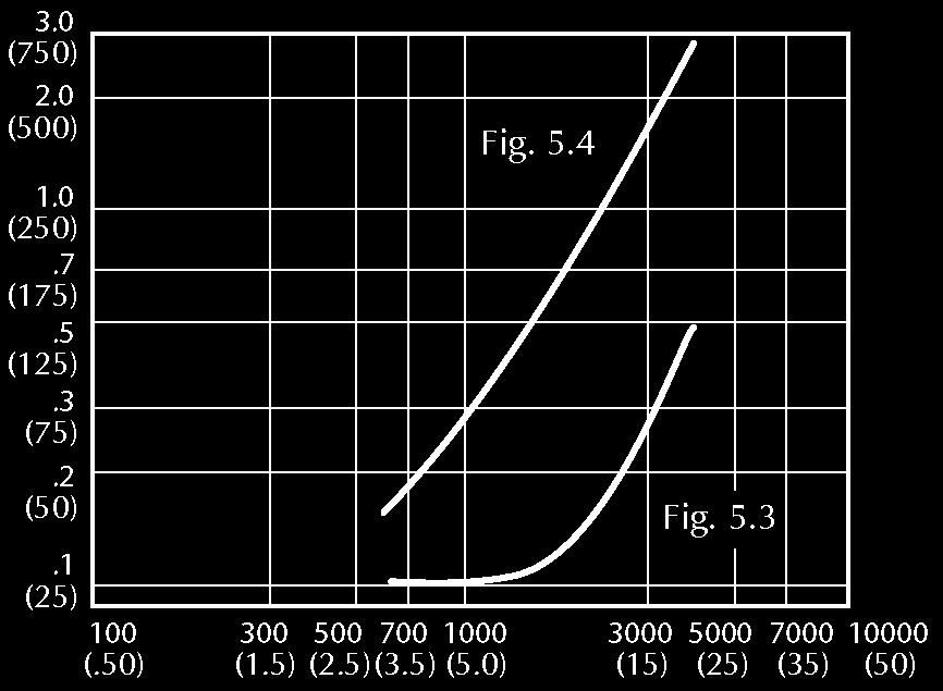
47 Differential Pressure in. wg and (Pa) PERFORMANCE DATA FOR MODELS BD-1, BD- and BD- LEAKAGE Leakage SCFM and (m/s) Tested per AMCA Std. 00, fig.. Size Tested: " x " BD-1 Pressure Drop in. wg and (Pa) PRESSURE DROP Face Velocity fpm and (m/s) Tested per AMCA Std. 00, fig.. Size Tested: " x " BACKDRAFT DAMPERS BD- Differential Pressure in. wg and (Pa) Differential Pressure in. wg and (Pa) Leakage SCFM and (m/s) Tested per AMCA Std. 00, fig.. Size Tested: " x " BD- Pressure Drop in. wg and (Pa) Pressure Drop in. wg and (Pa) Face Velocity fpm and (m/s) Tested per AMCA Std. 00, fig.. Size Tested: " x " Leakage SCFM and (m/s) Tested per AMCA Std. 00, fig.. Size Tested: " x " Face Velocity fpm and (m/s) Tested per AMCA Std. 00, fig.. Size Tested: " x "


 max.")
![pre-opening pressure] and medium velocity](/docs-images/81/83795072/images/48-4.jpg "[000 fpm (1 m/s)] systems.")

 reversal pressure, in.")
] systems.")


![fpm ( m/s)] systems.](/docs-images/81/83795072/images/48-11.jpg "PRESSURE RELIEF DAMPERS Sleeve Frame The")


48 Models PR-, PR-11, PR-1 and PR-1 The model PR- is designed for in-duct mounting with tri-formed blades for low pressure [ in. wg (00 Pa) reversal pressure, 1 in. wg (0 Pa) max. pre-opening pressure] and medium velocity [000 fpm (1 m/s)] systems. End View Field Assembled Mullion PR- The model PR-11 is designed for flanged duct mounting with single thickness blades for low pressure [ in. wg ( Pa) reversal pressure, in. wg (00 Pa) max. pre-opening pressure] and medium velocity [900 fpm (0 m/s)] systems. Section View Partial Section View of Sleeve Frame PR-11 The model PR-1 is designed for flanged duct mounting with airfoil blades for medium pressure [. in. wg (0 Pa) reversal pressure, in. wg (00 Pa) max. pre-opening pressure] and high velocity [ fpm ( m/s)] systems. PRESSURE RELIEF DAMPERS Section View Partial Section View of Sleeve Frame The model PR-1 is designed for flanged duct mounting with airfoil blades for high pressure [1. in. wg (0 Pa) reversal pressure, in. wg (0 Pa) max. pre-opening pressure] and high velocity [00 fpm ( m/s)] systems. Section View Mullion PR-1 PR-1 Pressure Relief Dampers are designed to begin opening and relieve air at a re-determined amount of water gauge pressure. They also prevent the reversal of air flow.
 900 fpm (0 m/s) Velocity: Max. Diff. Pressure: in. wg (00 Pa) in. wg ( Pa) Max.")
 undersize Max. Panel Size: W x 9 () H.")
49 PERFORMANCE DATA FOR MODELS PR-, PR-11, PR-1 and PR-1 STANDARD SPECIFICATIONS FOR MODELS PR- AND PR-11 Inches are shown, numbers in ( ) are mm Product: PR- PR-11 Max. Face 000 fpm (1 m/s) 900 fpm (0 m/s) Velocity: Max. Diff. Pressure: in. wg (00 Pa) in. wg ( Pa) Max. Temperature: 0 F ( C) (without seals) F ( C) (with optional seals) 0 F ( C) (without seals) F ( C) (with optional seals) Dimensions: A and B dimensions are opening sizes. A and B dimensions are inside damper frame or sleeve Dampers will be fabricated 1 / (.) undersize Max. Panel Size: W x 9 () H. When a larger unit is W x 9 () H required, damper will be fabricated in multiple sections for field assembly Min. Panel Size: (1) W x / (19) H (1) W x (1) H Frame: (Hat channel/pr-) (Channel/PR-11) Mullion: Frame: 1 / (10) x / (.) x 1 Ga. (1.) galv. steel hat channel for in-duct mounting. Dampers under H will have a flat Ga. (.) galv. steel plate at head and sill (Sleeve for In-duct mounting) Blades: 1 Ga. (1.) galv. steel, () max. and (1) min. blade width. (0) x (1) x 1 Ga. (1.9) galv. steel through (19) W or H (0) x (1) x 1 Ga. (.) galv. steel 1 / 1 (10) through 9 () W or H (0) x 1 () x 1 Ga. (1.9) galv. steel channel (0) x 1 Ga. (1.9) galv. steel through (19) W or H (0) x 1 Ga. (.) galv. steel 1 / 1 (11) through 9 () W or H 1 Ga. (1.) galv. steel, through () length. 1 Ga. (.) galv. steel, from 1 / 1 (0) through length. 1 / (191) max. width PRESSURE RELIEF DAMPERS Axles: 1 / (1.) dia. plated steel, stub 1 / (1.) dia. plated steel stub through (11) W / (1.) dia. plated steel full length 1 / 1 (1) through () W / (19) dia. plated steel stub 1 / 1 (0) through 0 (1) W / (19) dia. plated steel full length 0 1 / 1 (1) through W All axles with weights are full length. Bearings: Press fit ball bearings Press fit ball bearings Linkage: Plated steel brackets, brass barrels, and / 1 (.9) dia. plated steel rod LEAKAGE IN SCFM Plated steel brackets, brass barrels, and / 1 (.9) dia. plated steel rod. Dampers have double linkage on panels wide. over wide Stops: Galvanized steel angle Galvanized steel angle Finish: Mill Mill Actuator: Counter balance and pressure set weights to start to open at a pre-set pressure. Available range is.1 in. wg (1 Pa) through 1 in. wg (0 Pa) Counter balance and pressure set weights to start to open at a pre-set pressure. Available range is. in. wg ( Pa) through in. wg (9 Pa) Differential Pressure in. wg and (Pa) PR- Differential Pressure in. wg and (Pa) PR-11 Leakage SCFM and (m/s) Size Tested " X " Leakage SCFM and (m/s) Size Tested" X " NOTE: All data tested per AMCA Standard 00, fig.. wall-mounted. Construction options are the same as those for models BD-0/1 and BD-1 Backdraft Dampers. 9
50 PERFORMANCE DATA FOR PRESSURE RELIEF DAMPERS PR-1 LEAKAGE IN SCFM PR-1 Differential Pressure in. wg and (Pa) Differential Pressure in. wg and (Pa) Leakage SCFM and (m/s) Size Tested " X " Leakage SCFM and (m/s) Size Tested " X " NOTE: All data tested per AMCA Standard 00, fig.. wall-mounted. Construction options are the same as those for models BD- and BD- Backdraft Dampers. STANDARD SPECIFICATIONS FOR MODELS PR-1 AND PR-1 Inches are shown, numbers in ( ) are mm PRESSURE RELIEF DAMPERS 0 Product: PR-1 PR-1 Max. Face Velocity: fpm ( m/s) 00 fpm ( m/s) Max. Diff. Pressure:. in. wg (0 Pa) 1. in. wg (0 Pa) Max. Temperature: Dimensions: (Hat channel/pr-) (Channel/PR-11) 0 F ( C) (without seals) F ( C) (with optional seals) A and B dimensions inside damper frame or sleeve. A and B dimensions must include clearance required by the customer on sleeve frame dampers. Dampers will be fabricated to exact size. Max. Panel Size: W x 9 () H W x 9 () H Min. Panel Size: (1) W x (1) H (1) W x (1) H Frame: (0) x (1) x 1 Ga. (.) galv. steel through (19) W or H (Sleeve for In-duct mounting) (0) x (1) x Ga. (.) galv. steel 1 / 1 (10) through 9 () W or H 0 F ( C) (without seals) F ( C) (with optional seals) A and B dimensions are inside damper frame or sleeve. Damper with be fabricated to exact size. () x (1) x Ga. (.) galv. steel through 0 (1) W or H () x 1 / () x Ga. (.) galv. steel 0 1 / 1 (1) W through 0 (0) W or H () x 1 / () x 1 / (.) steel channel 0 1 / 1 (0) through 9 () W or H Mullion: (0) x 1 () x 1 Ga. (.) galv. steel channel () x () x 1 / () x Ga. (.) galv. steel channel Frame: (0) x 1 Ga. (.) galv. steel through (19) (0) x 1 Ga. (1.9) galv. steel through (19) W or H W or H (0) x Ga. (.) galv. steel 1 / 1 (11) through 9 ()W or H (0) x 1 Ga. (.) galv. steel 1 / 1 (11) through 9 () W or H Blades: 1 Ga. (1.) galv. steel, 1 / 1 (0) max. width 1 Ga. (1.) galv. steel, through (1) length 1 Ga. (1.9) galv. steel, 1 / 1 (1) through length 1 / 1 (0) max. width Axles: / (19) diameter plated steel, full length / (19) diameter plated steel, full length Bearings: Press fit ball bearings Press fit ball bearings Linkage: Plated steel brackets, brass barrels, and / 1 (.9) dia. plated steel rod. Double linkage on panels over 0 (0) wide Heavy-duty plated steel arms and bars with shoulder bolts, washers, and locknuts located outside airstream Stops: Galvanized steel angle Galvanized steel angle Finish: Mill with touch up on welds Mill with touch up on welds and one prime coat on black steel Actuator: Counter balance and pressure set weights to start to open at a pre-set pressure. Available range is. in. wg ( Pa) through in. wg (00 Pa) Counter balance and pressure set weights to start to open at a pre-set pressure. Available range is. in. wg (1 Pa) through in. wg (0 Pa)


51 Baffled Dampers Baffled dampers are custom designed for a specific set of control conditions. Baffles are placed between either parallel or opposed damper blades and the curvature of the baffles are designed to achieve the desired control characteristics. The amount of open area between parallel or opposed blades of conventional dampers is tied to the degrees of blade rotation from 0 to 90 (closed to open). With the addition of baffles, the amount of open area between blades and baffles can be designed to be an amount that falls either between that of conventional parallel and opposed blades or less than the amount of opposed blades. Parallel blade dampers are applicable for: Two position control, allowing full flow when open or no flow when closed. Modulating control of mixing dampers or face and bypass dampers. Such dampers control an essentially constant total flow with a near constant differential pressure. Parallel blade dampers, at the open position, have a little more open area as there is with one damper open and the other damper closed. Opposed blade dampers, at the open position, have a restricted open area and total flow is considerable less than when one damper is open and other one closed. Baffles can be used to refine the control characteristics of parallel blade dampers. Opposed blade dampers are applicable for: Manual balancing dampers. Modulating control. Most damper are oversized, because of consideration of other components in the system, such as filters, coils, etc. Baffles can be used to improve the control characteristics of the oversized dampers. Baffle dampers can be designed for: Dampers constructed for smelting operation. SPECIALTY DAMPERS Controlling systems where neither the conventional parallel or opposed blade damper configuration provides the desired control characteristics. This usually occurs where face velocities are relatively low and/or the differential pressure is relatively high. In such applications, the damper is trying to control the full flow with the damper at a near closed position. With the addition of baffles, the control range of the damper is 0 to 0 open. To determine if your application could be better controlled by the use of a baffled damper, determine the full flow face velocity and the desired differential pressure across the damper at that flow, check the number of degrees that the parallel or opposed blade damper would be open to achieve those conditions. If the open position of the damper is less than, the control characteristics could be improved with the use of a baffled damper. Typical Baffle Damper Cross-Section Vernier Control SMELTER OPERATION Dampers required to have finer control curve than obtainable with conventional multi-blade dampers. Controls air flow over wide, predetermined pressure drop range. ABSOLUTE FILTER OPERATION When placed in series with the filter, and controlled to maintain a constant pressure drop across the damper and filter, maintains a constant volume flow through the filter when clean or dirty. VERNIER CONTROL When used in conjunction with conventional opposed blades, can be used to control full flow when conventional and baffled blades are used together and control low flow caused by stack offset or loss of fan power, by closing conventional blade and controlling with baffled blades only. 1
52 Zone Damper Zone dampers are used to control the mixture of air from packaged heating, ventilating and air conditioning units. They are a special application for a face and by-pass damper (hot and cold deck) and are divided into individually operated sections (zones) controlling air temperatures in various building areas. AWV manufactures zone dampers with various dimensions and zone quantities to meet specific job requirements. Face View SPECIALTY DAMPERS STANDARD SPECIFICATIONS FOR ZONE DAMPERS Inches are shown, numbers in ( ) are mm Frame: () x 1 / () x 1 Ga. (.) galvanized steel channel Blades: 1 Ga. (1.) galvanized steel, max. (1) width Deck Divider: 1 / (10) x 1 Ga. (.) galvanized steel plate Zone Baffles: 1 / (10) x 1 Ga. (.) galvanized steel plate Axles: 1 / (1.) stainless steel Bearings: O.I.B. with stainless steel thrust washers Extended Shaft: 1 / (1.) diameter stainless steel to extend (1) beyond frame Stops: Top and bottom both decks, side stops hot deck only, 1 Ga. (1.) galvanized steel Finish: Aluminum touch up


53 Custom Designed Dampers Various Applications and Materials This brochure contains many different types of dampers for use in a variety of applications. However, you may not have found the exact damper model that meets your particular requirements. For close to 0 years, we have developed innovative dampers designs to meet the most exacting requirements. Temperatures from -0 F to 0 F. Pressures to 0 psi, velocities to,000 fpm. Clean air to highly corrosive and abrasive. Our designs include nuclear and fossil power stations dampers for use in baghouses, precipitators, scrubbers, boilers, air preheaters, gas turbine inlet and exhaust. We have also designed dampers for use in steel, aluminum and paper mills, cement plants, refineries, subways, tunnel, aircraft and submarines. Recent examples of our capabilities include: SPECIALTY DAMPERS UTILITY COAL FIRED INDUCED DRAFT FAN INLET BOX CONTROL DAMPER: Size: (0) x (11) Max. Face Velocity: Max. Differential Pressure: Max. Temperature: Max Torque: 00 fpm ( m/s) in. wg (110 Pa) 00 F (19 C) 1000 in.-lbs. (191 Nm) REFRACTORY LINED ROUND DAMPER: Size: Max. Face Velocity: Max. Differential Pressure: Max. Temperature: Max Torque: inside diameter 00 fpm (9 m/s) in. wg (0 Pa) 100 F (9 C) 0 in.-lbs. ( Nm) TUNNEL VENTILATION SAFETY DAMPERS: Size: (0) x (0) Max. Face Velocity: Max. Differential Pressure: Max. Temperature: 0 fpm (11 m/s) in. wg (00 Pa) 00 F (1 C) Regardless of the application, you can rely on the American Warming and Ventilating Custom Damper Group to develop practical, reliable, economical solutions to the most demanding customer requirements. Let us put our design knowledge to work for you on your next project.

54 Testing Information REGISTERED TESTING LABORATORY American Warming and Ventilating utilizes our fully equipped, registered Mestek Laboratory in the developing of new products, verification and value engineering of current products. The Laboratory is also used for testing required to meet projects with customer witnessing. TESTING To ensure continuous product development and performance, we have an AMCA* registered laboratory located at our Bradner manufacturing facility. Our facility is equipped to test differential pressures to 0 in. wg. and flow rates to 0,000 SCFM. The face of the chambers can accommodate dampers to foot square. Through the use of flexible ducting, we can test dampers and louvers larger than foot wide or high. Other tests available to our customers include reverse bend fatigue, slam shut under maximum air flow and pressure drop, cycle, endurance, bubble tight leakage, decay leakage and a 00 F industrial walk-in oven for testing our combination Fire/Smoke and Leakage rated (Smoke only) to 0 F and Tunnel Dampers to F. *(Approved for testing in accordance with AMCA Std. 00). QUALITY ASSURANCE Our QA program can be applied to products in the form of final inspection or full documentation - from material certification, nondestructive testing of welding, to final assembly. It is structured to meet the AEC s 1-point criteria as stated in CFR0, Appendix B, ANSI., and ASME NQA-1for inspection and testing. Also, the program has met the standards of audit teams from leading engineering firms and nuclear utilities. Testing Lab Bradner, Ohio TESTING CAPABILITIES INCLUDE: Air Duct Erosion of Fiberglass-lined Duct Bubble Tight Leakage Cycle Deflection Differential Pressures to 0 in. wg. Endurance Limit and Fatigue Flow rates to 0,000 SCFM High Velocity Pressure Testing on tempering air nozzles and quenchers Leakage Measurement Micro Strain Measurement Open & Close Timing Pressure Decay Reverse Bend Fatigue Slam shut under maximum air flow and close-off pressure on chamber and in-duct pressure drop Elevated temperature tests to 00 F Thermal Shock

55 Notes: AWV Manufacturing Plant Bradner, Ohio Phone: Fax: 19--1


56 A Mestek Company American Warming and Ventilating, 01 International Drive, Holland, Ohio, USA Phone: Fax: linkedin.com/company/american-warming-&-ventilating-a-mestek-company
Insulated Control Damper. 1/2 in. (13mm) 1/2 in. (13mm) 12 x 12 (305 x 305) 8 x 12 (203 x in. W x 120 in. H (3658mm x 3048mm) 5 in.
 1/2 in. (13mm) 12 x 12 (305 x 305) 8 x 12 (203 x in. W x 120 in. H (3658mm x 3048mm) 5 in.") R Application and Design The is a low leakage thermally insulated damper with extruded airfoil blades. features thermally broken frame and blade to eliminate the transfer of heat or cold penetration and
R Application and Design The is a low leakage thermally insulated damper with extruded airfoil blades. features thermally broken frame and blade to eliminate the transfer of heat or cold penetration and
Insulated Control Damper. 12 x 7 (305 x 178) 8 x 7 (203 x 178)
 8 x 7 (203 x 178)") R Application and Design The is a low leakage thermally insulated damper with extruded airfoil blades. features thermally broken blade to eliminate the transfer of heat or cold penetration and reduced
R Application and Design The is a low leakage thermally insulated damper with extruded airfoil blades. features thermally broken blade to eliminate the transfer of heat or cold penetration and reduced
A Complete Line of Quality Products for Marine Applications
 american warming and ventilating A Mestek Company A Complete Line of Quality Products for Marine Applications 1 About AWV Marine Dampers At American Warming and Ventilating, we are committed to design
DAMPERS FOR COMMERCIAL & INDUSTRIAL APPLICATIONS IN HEATING, VENTILATING & AIR CONDITIONING
 PUB. NO. 732-3 DAMPERS FOR COMMERCIAL & INDUSTRIAL APPLICATIONS IN HEATING, VENTILATING & AIR CONDITIONING The most widely used dampers in commercial HVAC applications Control Dampers - Extruded Aluminum
Thermal Isolation Break. Frame Type Channel Quick Connect Single or Reverse Flange Blade Action Parallel Opposed Parallel Opposed Parallel Opposed
 Application The is a low leakage thermally insulated damper with extruded airfoil blades. features broken blade which minimized the transfer of thermal energy and reduce condensation. It s also IECC (International
VCD-23. Flange Options. Size Limitations
 Application and Design The series is a ruggedly built low leakage control damper intended for application in low to medium pressure and velocity systems. A wide range of electric and pneumatic actuators
Insulated Control Damper. 1/2 in. (13mm) 1/2 in. (13mm) 12 x 12 (305 x 305) 8 x 12 (203 x 305) 5 in. (127mm) Parallel
 1/2 in. (13mm) 12 x 12 (305 x 305) 8 x 12 (203 x 305) 5 in. (127mm) Parallel") Application and Design The is a low leakage thermally insulated damper with extruded airfoil blades. features thermally broken frame and blade to eliminate the transfer of heat or cold penetration and
Application and Design The is a low leakage thermally insulated damper with extruded airfoil blades. features thermally broken frame and blade to eliminate the transfer of heat or cold penetration and
Model VCD-18. Ratings. Blade Operation. Size Limitations. Features & Options
 Application and Design The series is a general purpose, low leakage control damper intended for application in low pressure and velocity systems. atings Pressure: 2 in. wg (.5 kpa) - pressure differential.
ARROW INDUSTRIAL PRODUCTS
 IP-2R ARROW INDUSTRIAL PRODUCTS For Applications in Industrial, Power Plant & Commercial Projects ARROW UNITED INDUSTRIES ARROW UNITED INDUSTRIES has specialized in the manufacturing of air control products
Model VCD-20. Control Damper. Application. 3V Blade. Ratings. Flange Options. Size Limitations. Blade Operation. Features and Options
 Application The series is a general purpose control damper for applications as an automatic control or manual balancing damper with low to medium pressure and velocity systems. A wide range of electric
Thermal Isolation. Break
 Application and Design The is a low leakage thermally insulated damper with extruded airfoil blades. features thermally broken frame and blade will minimize the transfer of thermal energy and reduces condensation.it
Baked Enamel, Epoxy, Hi Pro Polyester, Industrial Epoxy, Kynar/Hylar (70%) Permatector. Single or Reverse Flange 8 x 6 (203 x 178)
 Permatector. Single or Reverse Flange 8 x 6 (203 x 178)") Application and Design The is an extremely low leakage damper designed to meet the highest standards established for commercial control dampers. The is intended for application in medium to high pressure
Application and Design The is an extremely low leakage damper designed to meet the highest standards established for commercial control dampers. The is intended for application in medium to high pressure
ARROW UNITED INDUSTRIES
 IP-3R ARROW UNITED INDUSTRIES Building Tomorrow s Ventilation Today Heavy Duty Dampers Industrial, Power Plant & Commercial Applications ARROW UNITED INDUSTRIES has specialized in the design and manufacturing
HCD-230 Industrial Control Damper
 Application and Design Model is a heavy duty industrial control damper with a flanged frame. It is designed to control airflow and provide shut off in HVAC or industrial process control systems. A variety
ID-141x 12-Gauge Hat Channel Industrial Damper
 ID-141x 12-Gauge Hat Channel Industrial Damper Product Bulletin Code No. LIT-12011355 Issued June 12, 2013 Supersedes March 13, 2012 Since 1905, Johnson Controls has developed and refined air control products
HCD-135. Industrial Control Damper. Application and Design. Ratings (see page 2 and 3 for specific limitations) Standard Construction.
 Standard Construction.") Application and Design Model is a heavy duty industrial control damper with a flanged frame. It is designed to control airflow and provide shut off in HVAC or industrial process control systems. A variety
Application and Design Model is a heavy duty industrial control damper with a flanged frame. It is designed to control airflow and provide shut off in HVAC or industrial process control systems. A variety
Model SEVCD-33. Low Leakage Airfoil Control Damper. Application and Design. Ratings (See page 3 for specific limitations) Blade Operation
 Blade Operation") Application and Design The is a severe environment 316SS ultra low leakage control damper with rugged stainless steel airfoil blades designed to meet the highest standards established for commercial control
Application and Design The is a severe environment 316SS ultra low leakage control damper with rugged stainless steel airfoil blades designed to meet the highest standards established for commercial control
Model VCD-34. Low Leakage Insulated Airfoil CONTROL DAMPER. Ratings (See page 3 for specific limitations) Flange Options.
 Flange Options.") Application and Design The Series is a ruggedly built low leakage control damper with thermally insulated blades. The is intended for application in medium pressure and velocity systems. This model also
Application and Design The Series is a ruggedly built low leakage control damper with thermally insulated blades. The is intended for application in medium pressure and velocity systems. This model also
VCD-23. Low Leakage CONTROL DAMPER
 Application and Design The series is a ruggedly built low leakage control damper intended for application in low to medium pressure and velocity systems. A wide range of electric and pneumatic actuators
Model VCD-43 Extruded Airfoil Blade Control Damper
 Application and Design The is an extremely low leakage damper designed to meet the highest standards established for commercial control dampers. The is intended for application in medium to high pressure
Positive Seal Damper Blades with Vinyl Gaskets 2.5" SERIES 3000 SIDE MOUNT - NO FLANGE ORDERING METHOD FOR BACKDRAFT & MOTORIZED BACKDRAFT DAMPERS
 BACKDRAFT DAMPERS BLADE OPTION: SR: 0.016-0.020 roll formed aluminum with vinyl gasket - used with fan motors under 1 HP SE: 0.05 extruded aluminum with vinyl gasket - used with fan motors over 1 HP Positive
VCD-23 Low Leakage CONTROL DAMPER
 Application and Design The series is a ruggedly built low leakage control damper intended for application in low to medium pressure and velocity systems. A wide range of electric actuators are available.
Model VCD-33. Low Leakage Airfoil CONTROL DAMPER. Flange Options. Blade Operation. Size Limitations
 Application and Design The series is an ultra low leakage damper with rugged steel airfoil blades designed to meet the highest standards established for commercial control dampers. The airfoil shape reduces
Model VCD-40. Extruded Airfoil Blade Control Damper Narrowline Frame Construction. Application. Ratings. Flange Options.
 Model Application The is a low leakage high performance control damper with extruded aluminum airfoil blades. Blades are completely contained within the frame allowing the damper to be directly mounted
Series HCD Airfoil Control Damper
 Series HCD Airfoil Control Damper Model: HCD-1 The Holyoake HCD-1 is a precisely made volume and pressure control device with extremely low leakage when closed, (in the range of 0.003m 3 /s at 100 Pa).
Control Dampers. Leakage Performance. Model FDNB (Opposed Blade) FDQB (Parallel Blade) Galvanized 3V Blade Control Dampers
 FDQB (Parallel Blade) Galvanized 3V Blade Control Dampers") Control s Model FDCB (Opposed Blade) FDHB (Parallel Blade) Aluminum Low Leakage Control s Frame:.081 extruded aluminum Blades:.125 extruded aluminum Bearings: bronze oilite Linkage: *concealed in frame
Control s Model FDCB (Opposed Blade) FDHB (Parallel Blade) Aluminum Low Leakage Control s Frame:.081 extruded aluminum Blades:.125 extruded aluminum Bearings: bronze oilite Linkage: *concealed in frame
AMD-33 Air Measuring Station with VCD-33 Control Damper
 Application and Design Construction Standard Optional Frame Material Galvanized Steel - Frame Material Thickness 16 ga. (1.5mm) 12 ga. (2.7mm) Frame Type 5 in. x 1 in. hat channel - Blade Material Galvanized
VCD-43V. Vertical Airfoil Blade Control Damper. Application and Design. Ratings. Size Limitations. Features and Options: Pressure:
 Application and Design is a low leakage damper with vertical blade orientation designed to meet the highest standards established for commercial control dampers. The is intended for application in medium
FBV-43. Vertical Face & Bypass Control Damper Ultra Low Leakage Aluminum Frame Construction. Application and Design. Size Limitations.
 Application and Design The is a vertical style face and bypass low leakage damper. This model is intended for application in medium to high pressure and velocity systems. Smooth profile extruded aluminum
TED50XT EXTREME TEMPERATURE THERMALLY EFFICIENT, INSULATED BLADE DAMPER
 3900 Dr. Greaves Rd. Kansas City, MO 64030 (816) 761-7476 FAX (816) 765-8955 APPLICATION Ruskin model TED50XT is a low leak, thermally efficient damper with insulated extruded aluminum blades specially
Control Dampers and Fire Dampers. Volume 1 - March Insulated Control Dampers. Non-Insulated Control Dampers. Framing. Accessories.
 Insulated Control Dampers 2 Volume 1 - March 2010 6 Non-Insulated Control Dampers 8 Framing Accessories 9 Jack Shaft Steel Control Dampers Fire Dampers 10 11 Control Dampers and Fire Dampers 3900 Insulated
Introduction to Johnson Controls Dampers
 Damper and Actuator Product Guide 268.1 Damper Engineering Section Product Bulletin Issue Date 1297 Introduction to Johnson Controls Dampers For over 100 years, Johnson Controls has been the industry leader
Model VCD-20 3V CONTROL DAMPER
 R Application and Design The series is a ruggedly built general purpose damper for application as an automatic control or manual balancing damper. This model is intended for application in low to medium
Model SMD-302M. Modulating Smoke Damper. Application. Steel Airfoil Blades UL 555S Leakage Class II. Ratings. Size Limitations.
 Model Application The is a leakage rated modulating smoke damper with airfoil blades for operational closure in emergency smoke control situations. This model serves the function of both a control damper
CONTROL DAMPERS. Models 1810 & Model Model Model 1370
 CONTROL DAMPERS CONTROL DAMPERS MODELS 1810 & 1820 MANUAL ALANCING DAMPERS STEEL Models 1810 and 1820 have been engineering and designed for manual balancing applications in low to medium pressure and
AMD-33. Air Measuring Station with VCD-33 Control Damper. Application and Design. Features & Control Options
 Application and Design The combines the functionality of an accurate airflow measuring station and a low leakage control damper into one compact assembly that both measures and regulates airflow volumes
AMD-42-TD. Thermal Dispersion Air Measuring Station with VCD-42 Control Damper. Application and Design. Ratings. Features and Control Options
 Application and Design Thermal Dispersion Air Measuring Station with VCD-42 Control Damper The combines the functionality of a highly accurate thermal dispersion airflow measuring station and a low leakage
Model VCD-20V. 3V Vertical Control Damper. Application and Design. Ratings (See page 4 for specific limitations) Flange Options.
 Flange Options.") Application and Design The series is a vertical blade general purpose damper for application as an automatic control or manual balancing damper. This model is intended for application in low to medium
Application and Design The series is a vertical blade general purpose damper for application as an automatic control or manual balancing damper. This model is intended for application in low to medium
Model CFSD-211. Corridor Ceiling FIRE SMOKE DAMPER Steel 3V Blades UL 555S Leakage Class I
 Application and Design Model is a combination fire smoke damper that is UL classified to protect corridor ceiling penetrations as required by the Uniform Building Code. This model s operational ratings
SP Standard Profile. In Duct or Flanged to Duct Install Types OPPOSED ACTION PARALLEL ACTION. Extended Rear Flange Install Type
 1 SUBMITTAL DATA Series 1000 Air-Foil Control Damper SP Standard Profile 2" 50.8 mm In Duct or Flanged to Duct Install Types 4" 101.6 mm 6.4" 162.6 mm blades fully open 1" 25.4 mm Extended Rear Flange
HVAC Control & Balancing Dampers
 HVAC Control & Balancing Dampers Models VCD, MBD and RBD Selection Construction Performance H* W* 1June 2017 Design and Construction Features Bearing Shaft Extension Jamb Seal Commercial Control Dampers
PC-125x Counter-Balanced Backdraft Damper
 PC-15x Counter-Balanced Backdraft Damper Product Bulletin Code No. LIT-101180 Issued April 7, 015 Refer to the QuickLIT Web site for the most up-to-date version of this document. Since 1885, Johnson Controls
CONTROL DAMPERS. Model Model 1370CB. Model 1380CB. Model 1390CB B7
 CONTROL DAMPERS MODEL 1380 HIGH PERFORMANCE ACKDRAFT DAMPER EXTRUDED ALUMINUM HEAVY DUTY Model 1380 is a high performance extruded aluminum gravity operated backdraft damper for use in medium to heavy
SafidDampers SPK Standard Construction SPK Description SPK ( Flange Type )
") ( Flange Type ) SPK 30-100 Standard Construction FRAME: 160mm x 30mm x 1.5mm (16 Ga.) galvanized steel formed channel for flange connection. BLADES: 250mm max. width, 1.5mm (16 Ga.) galvanized steel. FINISH:
( Flange Type ) SPK 30-100 Standard Construction FRAME: 160mm x 30mm x 1.5mm (16 Ga.) galvanized steel formed channel for flange connection. BLADES: 250mm max. width, 1.5mm (16 Ga.) galvanized steel. FINISH:
BD-1600 Balancing/Zone Control Damper
 BD-1600 Balancing/Zone Control Damper Product Bulletin Code No. LIT-12012355 Issued September 2016 Refer to the QuickLIT website for the most up-to-date version of this document. The BD-1600 Balancing/Zone
SMD-201M. Application. Modulating Smoke Dampers Steel 3V Blades UL 555S Leakage Class I. Ratings. Operational Rating. Size Limitations.
 Application Model is a leakage rated modulating smoke damper with 3V style blades. The has been qualified to 2,000 fpm (10.2 m/s) and 6 in. wg (1.5 kpa) for operational closure in emergency smoke control
Model FSD-211. Application. Combination Fire Smoke Damper Steel 3V Blades UL 555S Leakage Class I UL /2 Hour Fire Resistance Rating.
 Application Model is a combination fire smoke damper with 3V style blades. This model is designed for operation and dynamic closure in emergency fire smoke situations. It is rated for airflow and leakage
AMD-42V Air Measuring Station with VCD-42V Control Damper
 Application and Design Construction Standard Optional Frame Material Galvanized Steel - Frame Material Thickness 16 ga. (1.5mm) 12 ga. (2.7mm) 14 ga. (2mm) Frame Type 5 in. x 1 in. hat channel - Blade
AMD-42 Air Measuring Station with VCD-42 Control Damper
 Application and Design W x H Construction Standard Optional Frame Material Galvanized Steel - Frame Material Thickness External Minimum Size 16 ga. (1.5mm) Internal Single Section Maximum Size Multiple
Model FSD-331 Combination Fire Smoke Dampers
 R APPLICATION Model is a high performance combination fire smoke damper with class I leakage. High strength airfoil blades ensure the lowest resistance to airflow in HVAC systems with velocities to 4000
AMD-23-TD. Thermal Dispersion Air Measuring Station with VCD-23 Control Damper. Application. Ratings. Features and Options
 Application Thermal Dispersion Air Measuring Station with VCD-23 Control Damper The combines the functionality of a highly accurate thermal dispersion airflow measuring station and a low leakage control
Model SMD-301. Smoke Damper Steel Airfoil Blades UL 555S Leakage Class I. Application. Ratings. Size Limitations. Features
 Model Application The is a leakage rated smoke damper with airfoil blades for operational closure in emergency smoke control situations. This model serves the function of both a control damper and smoke
Model FSD-331. Combination Fire Smoke Dampers. Application. Ratings. Features
 Application Model is a high performance combination fire smoke damper with Class I leakage. High strength airfoil blades ensure the lowest resistance to airflow in HVAC systems with velocities to 4000
Model FSD-212. Combination FIRE SMOKE DAMPERS
 R APPLICATION Model is a combination fire smoke damper with 3V style blades. The has been qualified to 2000 fpm (10.2 m/s) and 6 in. wg (1.5 kpa) for operation and dynamic closure in emergency fire smoke
FSD60, FSD60LP CoMBINAtIoN FIRe AND SMoKe DAMPeR
 3900 Dr. Greaves Rd. Kansas City, MO 64030 (816) 761-7476 FAX (816) 765-8955 FSD60, FSD60LP CoMINAtIoN FIRe AND SMoKe DAMPeR 1 1 /2 HoUR UL555 RAteD, UL555S LeAKAge CLASS 1 APPLICAtIoN Ruskin FSD60 Series
SafidDampers SPK Description. Standard Construction SPK ( Flange Type )
") ( Flange Type ) SPK 30-300 Description SPK 30 - Series The single and multi-leaf s with extruded aluminum airfoil blades are designed for quite, efficient and reliable air volume control in air conditioning
( Flange Type ) SPK 30-300 Description SPK 30 - Series The single and multi-leaf s with extruded aluminum airfoil blades are designed for quite, efficient and reliable air volume control in air conditioning
SD-1250 and SD-1600 Series Smoke Dampers
 SD-1250 and SD-1600 Series Smoke Dampers Product Bulletin Code No. LIT-1201592 Issued January 30, 2014 Supersedes October 14, 2013 Johnson Controls provides a leakage-rated damper for life safety smoke
Model DFD-230 Multi-Blade Fire Damper Steel 3V Blades UL555 3 Hour Fire Resistance Rating
 Application Model is a multi-blade fire damper with 3V style blades. The has been qualified to 4000 fpm (20.3 m/s) and 10 in. wg (2.5 kpa) for dynamic closure in emergency fire situations. Model may be
WD-300 Series. Backdraft Damper Vertical Mount - Horizontal Airflow. Application and Design. Ratings. Frame Styles. Size Limitations.
 Application and Design The WD300 series dampers are designed to prevent reverse airflow in horizontal exhaust applications. The WD300 features a pressure sensitive blade design that opens and remains open
CONTROL & BACKDRAFT DAMPERS. Nailor. Industries Inc.
 Nailor Industries Inc. CONTROL & ACKDRAFT DAMPERS 1 Contents Page No. Product Overview 4 Features of Nailor Control Dampers 1 Standard Performance Control Dampers Models 11/12 Low Leakage Vee-lades 11
FSD36, FSD36LP COMBINATION FIRE AND SMOKE DAMPER 1 1 /2 HOUR UL555 RATED, UL555S LEAKAGE CLASS 2
 3900 Dr. Greaves Rd. Kansas City, MO 64030 (816) 761-7476 FAX (816) 765-8955 FSD36, FSD36LP COMINATION FIRE AND SMOKE DAMPER 1 1 /2 HOUR UL555 RATED, UL555S LEAKAGE CLASS 2 APPLICATION Ruskin FSD36 Series
SMD-201. Application. Smoke Dampers Steel 3V Blades UL 555S Leakage Class I. Ratings. Operational Rating. Size Limitations.
 Application Model is a leakage rated smoke damper with 3V style blades. The has been qualified to 2,000 fpm (10.2 m/s) and 6 in. wg (1.5 kpa) for operational closure in emergency smoke control situations.
Model FSD-211. Combination FIRE SMOKE DAMPERS Steel 3-V Blades UL 555S Leakage Class I UL Hour Fire Resistance Rating
 R APPLICATION Model FSD-211 is a combination fire smoke damper with 3V style blades. The FSD-211 has been qualified to 2000 fpm (10.2 m/s) and 6 in. wg (1.5 kpa) for operation and dynamic closure in emergency
Model SSFSD-211. Combination Fire Smoke Damper 304 Stainless Steel 3V Blades UL 555S Leakage Class I UL Hour Fire Resistance Rating
 R Model Application Model is a 304SS combination fire smoke damper with 3V style blades. The is qualified to 2,000 fpm (10.2 m/s) and 6 in. wg (1.5 kpa). This damper may be installed vertically (with blades
WD-200 Series. Model WD-220 Flange Opposite Motor. Model WD-210 Flange on Motor Side. Model WD-200 No Flange. Motorized Backdraft Damper.
 Application The WD200 series are electrically motorized backdraft dampers that open when energized and spring return close when deenergized. The WD200 series are for horizontal or vertical mounting. Primary
VD-1600 Series Volume Control Dampers
 VD-1600 Series Volume Control Dampers Product Bulletin VD-1600 Code No. LIT-1201735 Issued April 2017 Refer to the QuickLIT website for the most up-to-date version of this document. Since 1885, Johnson
HVAC Control & Balancing Dampers
 HVAC Control & Balancing Dampers Models VCD, MBD and RBD Selection Construction Performance H* W* August 1 2013 HVAC Control and Balancing Dampers Commercial Control Dampers are used in buildings to regulate
Air Measuring Products. AMS Thermal Dispersion Pressure Differential
 Air Measuring Products AMS Thermal Dispersion Pressure Differential August 2014 1 Airflow Measuring Technologies Greenheck airflow measuring products are available with either differential pressure based
AD-1250 Airflow Measuring Station
 AD-1250 Airflow Measuring Station Product Bulletin Code No. LIT-12011472 Issued March 2016 Refer to the QuickLIT website for the most up-to-date version of this document. The AD-1250 Airflow Measuring
L O U V E R S & D A M P E R S
 L O U V E R S & D A M P E R S www.alggin.com CALGARY EDMONTON LETHBRIDGE 4540-46th Ave. SE 12110-154 St. NW 1126-36 St. N (403) 252-0132 (780) 424-0132 (403) 320-8732 sales@alggin.com edmsales@alggin.com
RM-1200 Slim Round Control Damper
 RM-1200 Slim Round Control Damper Product Bulletin Code No. LIT-12011358 Issued June 16, 2008 Since 1905, Johnson Controls has developed and refined air control products by providing the highest quality
When Time is Everything... We Manufacture in Days - Not Weeks!
 When Time is Everything... We Manufacture in Days - Not Weeks! DAMPERS ACCESS DOORS LOUVERS July 2014 Specializing In Products For The HVAC Industry 763-783-7173 fax: 763-785-6977 1-800-297-9360 Customer:
Motorized Fire Dampers
 Model : OMFD-611 (Fusible link and spring return actuator) GI steel sheet construction In accordance with UL555 & UL555S suitable for installation in walls and partitions having rating 2 Hrs. Static and
EnergyShield ES. Air Control and Shut off Dampers. Dampers Controls Fancoils. Ruskin Air Management Limited
 April 11 EnergyShield ES EnergyShield ES Air Control and Shut off Dampers Features Dampers suitable for systems requiring air control and low closed blade leakage characteristics. Low torque characteristics.
SMOKE DAMPERS SMOKE DAMPERS SMOKE DAMPERS
 SMOKE DAMPERS 96 97 SD SERIES SD for Use in Dynamic Systems Types Galvanized Steel Construction as Standard.. Sleeve Type, Model: SD - 0-00. Circular Type, Model: SD - 50-00. Oval Type, Model: SD - 60-00
A. Product Data: For each type of product. TLC ENGINEERING FOR ARCHITECTURE - PROJECT NO AIR DUCT ACCESSORIES
 SECTION - PART 1 - GENERAL 1.1 RELATED DOCUMENTS A. Drawings and general provisions of the Contract, including General and Supplementary Conditions and Division 01 Specification Sections, apply to this
CONTROL DAMPERS GENERAL PRODUCT OVERVIEW MODELS 1010 & 1020 LOW LEAKAGE CONTROL DAMPER VEE GROOVE BLADE MODELS 1012 & 1022 STANDARD CONTROL DAMPER
 GENERAL PRODUCT OVERVIE ith today s stringent design criteria for energy efficient 'green' building technology and indoor air quality, individual product engineering, testing and quality of workmanship
VOLUME CONTROL DAMPERS
 VOLUME CONTROL DAMPERS CONSTRUCTION FEATURES FRAME Roll formed 16 gauge galvanized steel channel with welded corners. X-Standard, Z-optional AXLES Roll formed 18 gauge galvanized steel. 1/2" Round chrome
Air Measuring Products AMD AMS IAQ
 Air Measuring Products AMD AMS IAQ January 1 2012 Air Measuring Products Why is outside air measurement important? There are many significant benefits to monitoring outside air volumes. By measuring the
AMCA MEMBER. American Warming and Ventilating. A Mestek Company. Tunnel Ventilation, Smoke Control, & Fire Dampers Technical Information
 AMCA MEMBER American Warming and Ventilating A Mestek Company Tunnel Ventilation, Smoke Control, & Fire Dampers Technical Information American Warming and Ventilating, 7301 International Drive, Holland,
SECTION AXIAL HVAC FANS
 SECTION 233413 - AXIAL HVAC FANS 1. PART 1 GENERAL 1.1. RELATED DOCUMENTS A. Drawings and general provisions of the Contract, including General and Supplementary Conditions and Division 01 Specification
DAMPERS WE CONTROL AIR
 WE CONTROL AIR Ver. 1 January 2017 index >> VOLUME CONTROL DAMPER - 3VCD SERIES >> VOLUME CONTROL DAMPER - AVCD SERIES >> LOW-LEAKAGE VOLUME CONTROL DAMPER - LVCD SERIES >> ROUND VOLUME CONTROL DAMPER
Actionair Control and Shut Off Dampers
 December 2003 Air/Shield (Incorporating Energy/Shield ES35 & ES36) Actionair Control and Shut Off Dampers Air/Shield Aerofoil Air Control Dampers Air/Shield Aeroseal Air Control and Shut-Off Dampers Energy/Shield
LOW LEAKAGE VOLUME CONTROL DAMPER
 LOW LEAKAGE VOLUME CONTROL DAMPER On Time Delivery According to Standard Customization Quality Cooperation LOW LEAKAGE VCD CATALOG REV 00 APRIL 2018 2017_04_08 ABOUT US Sharqawi Air distribution systems
DF / DFB / DFC DOUBLE WIDTH DOUBLE INLET FORWARD CURVED FANS
 Catalog 6131 DF / DFB / DFC DOUBLE WIDTH DOUBLE INLET FORWARD CURVED FANS FOR ORIGINAL EQUIPMENT MANUFACTURES SERIES 1600 1/98 APPLICATIONS AND AVAILABLE TYPES DF - DFB - DFC DOUBLE INLET FANS DOUBLE INLET
INDEX. Chapter1 6. air master. Volume Control Dampers
 Chapter1 6 INDEX 1 Volume control damper...:avcd...16.1 Standard sizes...16.2 Fixing details...16.2 How to order...16.2 Performance chart...16.3 2. Circular volume control damper....:avcd-c....16.4 Standard
HEAVY DUTY BALANCE AND CONTROL DAMPER B A L A N C E C O N T R O L SERIES
 HEAVY DUTY BALANCE AND CONTROL DAMPER B A L A N C E C O N T R O L HD SERIES MANUFACTURERS OF AIR/FIRE/SMOKE CONTROL PRODUCTS Product Description and Features Introduction The HD Series Multi-Leaf Volume
SECTION CONTROL DAMPERS
 SECTION 23 09 13.43 - CONTROL DAMPERS PART I - GENERAL 1.1 SECTION INCLUDES A. Airfoil Dampers, Heavy Duty Galvanized Steel B. Thermally Insulated Dampers, Heavy Duty Galvanized Steel C. Airfoil Dampers,
FSD60, FSD60LP COMBINATION FIRE AND SMOKE DAMPER 1 1 /2 HOUR UL555 RATED, UL555S LEAKAGE CLASS 1
 3900 Dr. Greaves Rd. Kansas City, MO 64030 (816) 761-7476 FX (816) 765-8955 FSD60, FSD60LP COMINTION FIRE ND SMOKE DMPER 1 1 /2 HOUR UL555 RTED, UL555S LEKGE CLSS 1 PPLICTION Ruskin FSD60 Series ultra
Bulletin BCF 103 DESIGN 10A BACKWARD INCLINED WHEELS
 Bulletin BCF 10 DESIGN 10A BACKWARD INCLINED WHEELS Proven Reliability in Industrial Environments and Corrosive Atmospheres Design 10A s with Backward Inclined Wheels Chicago s Design 10A is a rugged multi-purpose
B. Fabricate in accordance with ASHRAE handbooks and SMACNA duct manuals. A. Submit in accordance with Division-1 and Section
 SECTION 15910 DUCT ACCESSORIES PART 1 - GENERAL 1.01 RELATED DOCUMENTS A. Drawings and general provisions of Contract including General and Supplementary Conditions, Division-1 Specification Sections,
BAC, BAF, BAH Central Station Air Handlers
 PRODUCT DATA & INSTALLATION Bulletin B80-BA-PDI-5 Part # 1097717 PRODUCT SUPPORT web: b-rp.ca/bah email: ahu@b-rp.ca call: 1-844-893-3222 x527 scan: BAC, BAF, BAH Central Station Air Handlers Indoor and
VC Series. Volume Control Dampers M A N U F A C T U R E R S O F A I R, F I R E A N D S M O K E C O N T R O L P R O D U C T S
 V41706 VC Series Volume Control Dampers Roll formed steel blades with three material options DW144 compliant Flanged models with 65mm deep mechanically fixed casings Rectangular spigotted models with 85mm
CFSD Series. Product Description
 COMBINATION FIRE AND SMOKE DAMPER 1-1/2 HR LEAKAGE RESISTANCE CLASS II 250 O F FILE NO: R22165 Product Description Combination Fire / Smoke dampers provide an automatic means of localizing areas of smoke
Smoke Dampers. Installation Instructions
 Smoke Dampers Installation Instructions Installation Details 1. Dampers should be installed to provide proper operation and performance. They should be installed to permit them to maintain their shape
Blast Protection Damper
 Protection Damper plate shown as transparent height width 250mm wide 6.35mm thick blast plate bolted to damper frame 178mm 250mm standard depth 76mm standard flange Application The damper is designed for
BULLETIN 456. July 1997 VANEAXIAL FANS. Type W Direct Drive/Belt Driven. Model VW Direct Drive. Model VWBD Belt Driven
 BULLETIN 456 July 1997 VANEAXIAL FANS Type W Direct Drive/Belt Driven Model VW Direct Drive Model VWBD Belt Driven Aerovent certifies that the Type W Vaneaxial Fans shown herein are licensed to bear the
Blast Protection Damper
 height width 250mm standard 76mm standard flange Application The damper is designed for protection against sudden blasts and instantaneous pressure changes. Vertical and horizontal mounting applications
CCS Zone/Bypass Damper Assembly
 Code No. LIT-1900539 Issued July 15, 2011 UZR-xx-x, UBR-xx-x, UZD-0xxX0xx-x, UBD-0xxX0xx-x CCS Zone/Bypass Damper Assembly Description The Commercial Comfort System (CCS) Zone/Bypass Damper are zone control
MOTORIZED VOLUME DAMPER
 MOTORIZED VOLUME DAMPER 1 a perfect partner in performance... Our Product Ranges Dampers 1 Fire Dampers 2 Fire / Smoke Dampers 3 Volume Control Dampers 4 Motorized Control Dampers 5 Pressure Relief Dampers