PNEUMATIC MARINE PRODUCTS FOR PROPULSION CONTROL
|
|
|
- Nicholas Erick Flowers
- 5 years ago
- Views:
Transcription


1 PNEUMATIC MARINE PRODUCTS FOR PROPULSION CONTROL

 Control Unit - 3600 Caterpillar engine only. 7 II. LOGICMASTER HYDRAULIC CLUTCH CNTRL. UNITS Features and Specifications... 8 (R431007528) Control Unit.")
 Control Unit - Hydraulic. Throttle Interlock.. 11 IV. CLUTCH AND THROTTLE VALVES 1. THD-2-FM CONTROLAIR Valve... 12 2. HD-2-FM CONTROLAIR Valve... 14 3. HD-2-FC CONTROLAIR Valve... 15 4.")
2 2 Pneumatic Marine Products for Propulsion Control AVENTICS Corporation Marine Control Systems such as LOGICMASTER and GEARMASTER Propulsion Control Systems protect engines and equipment on tugs, offshore supply, and other vessels. INDEX TYPICAL SYSTEM SCHEMATICS LOGICMASTER Air Clutch... 3 LOGICMASTER Hydraulic Clutch... 4 GEARMASTER Hydraulic Clutch... 5 l. LOGICMASTER AIR CLUTCH CONTROL UNITS Features and Specifications... 6 (R ) Control Unit - Standard... 7 (R ) Control Unit - Standard w/ Shaft Brake... 7 (R ) Control Unit - Prop. Reversing Timing... 7 (R ) Control Unit Caterpillar engine only. 7 II. LOGICMASTER HYDRAULIC CLUTCH CNTRL. UNITS Features and Specifications... 8 (R ) Control Unit... 9 (R ) Control Unit... 9 III. GEARMASTER CONTROL UNITS AND SYSTEMS Features and Specifications (R ) Control Unit - Pneumatic Throttle Interlock. 11 (R ) Control Unit - Hydraulic. Throttle Interlock.. 11 IV. CLUTCH AND THROTTLE VALVES 1. THD-2-FM CONTROLAIR Valve HD-2-FM CONTROLAIR Valve HD-2-FC CONTROLAIR Valve HD-2-FX CONTROLAIR Valve HC-2-FM CONTROLAIR Valve HC-2-FX CONTROLAIR Valve H-2-FM CONTROLAIR Valve H-2-FX CONTROLAIR Valve H-3 & H-3-G CONTROLAIR Valve SH-3 CONTROLAIR Valve H-4 & H-4-G CONTROLAIR Valve A-2A CONTROLAIR Valve V. AIR LOGIC VALVES Gauge Block Shuttle Valve-Marine Logic Check Valve Flow Control Time Delay with Volume Air Volume Way Solenoid Normally Open Valve Way Solenoid Normally Close Valve Multifunction Valves - Pneumatic Pilot Multifunction Valves - Hydraulic Pilot Multifunction Adjustable Valve Pressure Regulator Subplate Hydraulic Shuttle Valve VI. ASSOCIATED COMPONENTS Shuttle Valve, Inline Quick Release Valve, Inline Relayair Valve Three-Position Cylinder A-2-H Actuator AA-1 Actuator Shuttle Panel - Two Station - Single Engine Shuttle Panel - Two Station - Twin Engine Control Transfer/Interlock Panel with Shuttle Valves VII. ELECTRONIC MARINE CONTROLS OVERVIEW See page 54 for overview of our Electronic Marine Controls.
3 Pneumatic Marine Products for Propulsion Control AVENTICS Corporation 3 Control Units & Systems Typical Control System Schematic LOGICMASTER AIR CLUTCH CONTROL SYSTEM
4 4 Pneumatic Marine Products for Propulsion Control AVENTICS Corporation Control Units & Systems Typical Control System Schematic LOGICMASTER HYDRAULIC CLUTCH CONTROL SYSTEM SINGLE ENGINE TWO CONTROL STATIONS
5 Pneumatic Marine Products for Propulsion Control AVENTICS Corporation 5 Control Units & Systems Typical Control System Schematic GEARMASTER HYDRAULIC CLUTCH CONTROL SYSTEM SINGLE ENGINE TWO CONTROL STATIONS


6 6 Pneumatic Marine Products for Propulsion Control AVENTICS Corporation Control Units & Systems LogicMaster Air Clutch Control Units LOGICMASTER AIR CLUTCH CONTROL UNITS
7 Pneumatic Marine Products for Propulsion Control AVENTICS Corporation 7 Control Units & Systems LogicMaster Air Clutch Control Units Ordering Information Model Part No. Old Part No. Description LMAC-1 R P Standard Unit LMAC-2 R P Standard Unit with shaft brake control signal LMAC-3 R P Unit with proportional reversing interlock timing LMAC-3C R P Unit with proportional reversing interlock timing for 3600 Series Caterpillar engine Weight:87 lbs. (40kg.) Maintenance kit for the above units is Part Number R ( P ). Caterpillar engine is a registered trademark of Caterpillar, Inc., Mossville, IL


8 8 Pneumatic Marine Products for Propulsion Control AVENTICS Corporation Control Units & Systems LogicMaster Hydraulic Clutch Control Units LOGICMASTER HYDRAULIC CLUTCH CONTROL UNITS & CONTROL SYSTEMS 800 TO 2,000 H.P OFFSHORE SUPPLY BOATS, CREW BOATS, TUGS, FISHING & GENERAL SERVICE BOATS LOGICMASTER Hydraulic Clutch Control Units combine proven, high-performance pneumatic components into factory assembled, tested and pre-timed units ready for shipboard installation and operation. All operating valves are subbase mounted for simplified service, maintenance and troubleshooting.
9 Pneumatic Marine Products for Propulsion Control AVENTICS Corporation 9 Control Units & Systems LogicMaster Hydraulic Clutch Control Units Port Numbers 1A - Ahead Out 1C - Ahead In 3A - Astern Out 3C - Astern In 8A - Speed Out 8C - Speed In GP - Gear Pressure GT - Hydraulic Safety Return BR - Shaft Brake Signal SUP - Supply Ordering Information Model Part No. Old Part No. Description LM1 R P Unit less shaft brake control LM2 R P Unit with shaft brake control signal R P Maintenance kit for R (Old Part No. P ) R P Maintenance kit for R (Old Part No. P ) Weight: 31 lbs. (14.1kg.)


 R431007069 - with")
10 10 Pneumatic Marine Products for Propulsion Control AVENTICS Corporation Control Units & Systems GearMaster Propulsion Control Systems GEARMASTER MARINE PROPULSION CONTROL SYSTEMS HYDRAULIC CLUTCH REVERSE GEARS 200 TO 1200 H.P. TOWBOATS, TUGS, TRAWLERS, SEINERS R with pneumatic clutch/throttle interlock (Old Part No. P ) R with hydraulic clutch/throttle interlock (Old Part No. P )


 Maintenance kit for R431007068 (Old Part No.")
11 Pneumatic Marine Products for Propulsion Control AVENTICS Corporation 11 Control Units & Systems GearMaster Propulsion Control System Ordering Information Part No. Old Part No. Description R R P Pneumatic throttle interlock unit P Hydraulic throttle interlock unit R P R P Weight: 15 lbs. (6.8 kg.) Maintenance kit for R (Old Part No. P ) Maintenance kit for R (Old Part No. P )


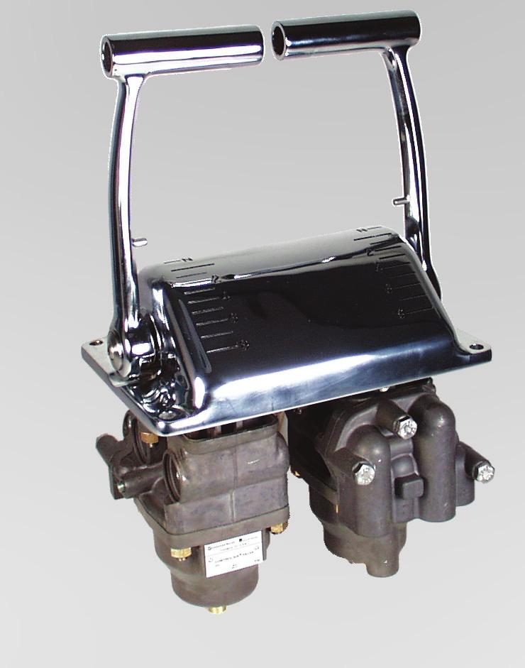
12 12 Pneumatic Marine Products for Propulsion Control AVENTICS Corporation Controlair Valves Model THD-2-FM Twin Engine Marine Control Valve THD-2-FM valves provide single handle control for propulsion direction and engine speed for two engines. This top of the line model is ruggedly built from nonferrous materials and has an attractive chrome-plated brass cover with chrome handles. The completely enclosed cover and rugged construction make it ideal for exposed station installations. Fore or aft movement to either control handle from neutral to the clutch position delivers supply pressure into the appropriate ahead or astern control line to engage the clutch. Further movement increases the pressure signal delivered to the engine governor. The neutral and clutch positions are detented for positive position indication. An adjustable friction brake holds the handles in any selected position. Models are available in psi and psi pressure ranges.
13 Pneumatic Marine Products for Propulsion Control AVENTICS Corporation 13 Controlair Valves Model THD-2-FM THD-2-FM Order Information: Part No. Old Part No. Description R P THD-2-FM (10-65 PSI) R P THD-2-FM (30-70 PSI) Maintenance kit (2 Required) R (Old Part No. P ) MAX. INLET AIR 200 PSI (13.8 BAR) TEMPERATURE -40 F TO 160 F (-40 C TO 71 C) PORT CONNECTIONS: 2 = SUPPLY 1 = CLUTCH 3 = CLUTCH 8 = SPEED WEIGHT: 25 LBS. (11.3 KG.)


14 14 Pneumatic Marine Products for Propulsion Control AVENTICS Corporation Controlair Valves Model HD-2-FM HD-2-FM Valves provide single handle control for propulsion direction and engine speed. This middle of the line model is ruggedly built from non-ferrous materials and has an attractive chrome plated bronze cover with a chrome handle. The completely enclosed cover and rugged construction make it ideal for exposed station installations. Fore or aft movement of the control handle from neutral to the clutch position delivers supply pressure into the ahead or astern control line to engage the appropriate clutch. Further movement increases the pressure signal delivered to the engine governor. The neutral and clutch positions are detented for positive position indication. The HD-2-FM is designed with an L-shaped handle so that two units can be mounted side by side for operation with one hand. An adjustable friction brake holds the handle in any selected position. HD-2-FM Order Information: MAX. INLET AIR PORT CONNECTIONS: Designation Part No. Old Part No. Setting 200 PSI (13.8 BAR) 2 = SUPPLY HD-2-FM R P PSI 1 = CLUTCH HD-2-FM R P PSI TEMPERATURE 3 = CLUTCH HD-2-FM R P PSI -40 F TO 160 F 8 = SPEED Maintenance kit R (Old Part No. P ) (-40 C TO 71 C) WEIGHT: 12 LBS. (5.44 KG.)


15 Pneumatic Marine Products for Propulsion Control AVENTICS Corporation 15 Controlair Valves Model HD-2-FC The HD-2-FC CONTROLAIR Valve is a handle operated pressure control and directional flow control valve. It contains two 3-way directional valves and a pressure regulating portion, which are arranged to furnish inlet air pressure to two directional clutch control lines and graduated pressure to one infinite positioning speed control line. The selection between the two clutch control lines depends upon handle movement to either side of Neutral position. The pressure in the speed control line is proportional to the position of the handle in either quadrant. The cover is die-cast aluminum with grey textured polyester paint, with stainless steel handle, hub and yoke. The angled handle, so designed that when mounted side by side they can be operated by one hand, is equipped with an adjustable friction brake that will hold the handle in any selected position. HD-2-FC Order Information: Designation Part No. Old Part No. Setting Style HD-2-FC R P PSI Right Hand HD-2-FC R P PSI Left Hand Maintenance kit R (Old Part No. P )
16 16 Pneumatic Marine Products for Propulsion Control AVENTICS Corporation Controlair Valves Model HD-2-FX The HD-2-FX valve provides simple and efficient single handle control for propulsion direction and engine speed. It is frequently used as an engine room control, or on smaller craft as a bridge control. Lightweight and rugged, non-ferrous construction, HD-2-FX valves are made of anodized die-cast aluminum for economy. The lever remains in the position where released. Holding friction is adjustable. Functional operation is the same as HD-2-FM and HD-2-FC CONTROLAIR valves. MAX. INLET AIR 200 PSI (13.8 BAR) TEMPERATURE -40 F TO 160 F (-40 C TO 71 C) PORT CONNECTIONS: 2 = SUPPLY 1 = CLUTCH 3 = CLUTCH 8 = SPEED WEIGHT: 7 LBS. (3.17 KG.) HD-2-FX Order Information: Part No. Old Part No. Pressure Cover R P PSI Plain R P R P R P PSI Plain PSI Plain PSI Plain R P PSI Chrome* R P *Chrome cover and handle yoke PSI Plain Maintenance kit R (Old Part No. P )


17 Pneumatic Marine Products for Propulsion Control AVENTICS Corporation 17 Controlair Valves Model HC-2-FM The HC-2-FM valve is designed for open deck marine service and is the same as the HC-2-FX CONTROLAIR valve, except it features longer handle travel, more accurate positioning and a polished chrome plated bronze cover and handle. The valve is a lever operated, pressure regulating, 4-way directional valve. It consists of two 3-way directional valves and a 3-way pressure regulating portion. The regulating portion furnishes inlet air to the directional valves. Each directional valve has its own outlet port. Initial lever movement from mid position selects the outlet port to be activated. Further lever movement in the same direction controls the outlet pressure at that point. The opposite port remains connected to atmosphere. Lever remains in the position where released. Handle holding friction is adjustable. Use these valves to control two clutches, a clutch and a brake, two single acting cylinders or a double acting cylinder...wherever you want to selectively control pressure in either of two separate air lines with one lever HC-2-FM Order Information: PANEL MOUNTING CUTOUT Part No. Old Part No. Pressure Style Handle Travel R P PSI Chrome 80 Maintenance kit R (Old Part No. P )


18 18 Pneumatic Marine Products for Propulsion Control AVENTICS Corporation Controlair Valves Model HC-2-FX The H-2-FX valve is a lever operated, pressure regulation, 4-way directional valve made of anodized die-cast aluminum. It consists of two 3-way directional valves and a 3-way pressure regulating portion. The regulating portion furnishes inlet air to the directional valves. Each directional valve has its own out port. Initial lever movement from mid position selects the out port to be activated. Further lever movement in the same direction controls the outlet pressure at that port. The opposite port remains connected to atmosphere. Lever remains in the position where released. Handle holding friction is adjustable. Use these valves to control two clutches, a clutch and a brake, two single acting cylinders or a double acting cylinder...wherever you want to selectively control pressure in either of two separate air lines with one lever. HC-2-FX Order Information: Part No. Old Part No. Pressure R P PSI R P PSI R P PSI R P PSI R P PSI Maintenance kit R (Old Part No. P )


 H-2-FM Order Information: Delivery Pressure Designation Part No. Old Part No.")
19 Pneumatic Marine Products for Propulsion Control AVENTICS Corporation 19 Controlair Valves Model H-2-FM The H-2-FM valve is designed for open deck marine service and features handle travel of 78, plus accurate pressure control and a polished chrome plated bronze cover, handle and grip. This valve controls engine governor operation permitting the engine to be run at advanced speed for warm-up and check-out without engaging the clutch. After engine warm-up, control is transferred to the bridge. MAX. INLET AIR PORT CONNECTIONS: 200 PSI (13.8 BAR) 2 = SUPPLY 1= CONTROL OUT TEMPERATURE 3 = CONTROL OUT -40 F TO 160 F 8= PLUGGED (-40 C TO 71 C) WEIGHT: 12 LBS. (5.44 kg.) H-2-FM Order Information: Delivery Pressure Designation Part No. Old Part No. Position A Position B Style H-2-FM R P PSI 10 PSI Right Hand H-2-FM R P PSI 10 PSI Right Hand H-2-FM R P PSI 65 PSI Left Hand H-2-FM R P PSI 70 PSI Left Hand H-2-FM R P PSI 30 PSI Right Hand Maintenance kit R (Old Part No. P )


 2 = SUPPLY 1= CONTROL OUT TEMPERATURE 3 = CONTROL OUT")
 H-2-FX Order Information: Part No. Old Part No.")

20 20 Pneumatic Marine Products for Propulsion Control AVENTICS Corporation Controlair Valves Model H-2-FX The H-2-FX CONTROLAIR valve is a lever operated regulating valve used for engine warm-up applications. Installed in the engine room, this valve controls governor operation, permitting the engine to be run at advanced speed for warm-up and check-out without engaging the clutch. After engine warm-up, control is transferred to the fridge. It is made of anodized die-cast aluminum. 92 YOKE ASSEMBLY AS SHOWN - REVERSE ASSEMBLY FOR 78 HANDLE TRAVEL MAX. INLET AIR PORT CONNECTIONS: 200 PSI (13.8 BAR) 2 = SUPPLY 1= CONTROL OUT TEMPERATURE 3 = CONTROL OUT -40 F TO 160 F 8= PLUGGED (-40 C TO 71 C) WEIGHT: 7 LBS. (3.17 kg.) H-2-FX Order Information: Part No. Old Part No. Pressure "C" Handle Travel R P PSI 92 R P PSI 92 R P PSI 78 Maintenance kit R (Old Part No. P )

 with the initial 1/16 (1.")
 H-3-G This design is similar to the H-3 CONTROLAIR except the spring housing area is sealed and a biasing")

 H-3 Order Information: Part No. Old Part No.")

 Maintenance kit (Roller ass'y.) R431006648 (Old Part No.")
21 Pneumatic Marine Products for Propulsion Control AVENTICS Corporation 21 Controlair Valves Models H-3 & H-3-G H-3 The H-3 CONTROLAIR Valve is equipped with a roller for operation by a cam or a similar mechanical device. Graduated pressure which is directly proportional to the amount of downward movement of the roller lever is delivered from the OUT port. Total movement is approximately 5/16 (7.9 mm) with the initial 1/16 (1.6 mm) travel used to close the exhaust valve. Approximate weight 4.5 lbs. (2.04 Kg) H-3-G This design is similar to the H-3 CONTROLAIR except the spring housing area is sealed and a biasing control pressure can be introduced through the tapped lower housing port to the underside of the diaphragm. By varying this signal, the output of the H-3-G CONTROLAIR can be biased or adjusted in proportion. This bias signal must be lower than the output signal. Approximate weight 5 lbs. (2.27 Kg) H-3 Order Information: Part No. Old Part No. Pressure R P PSI R P PSI R P PSI R P PSI R P PSI R P PSI R P PSI Maintenance kit R (Old Part No. P ) Maintenance kit (Roller ass'y.) R (Old Part No. P ) H-3-G Order Information: Part. No. Old Part No. Pressure Ports R P PSI 1/4-18 R P PSI 1/4-18 Maintenance kit R (Old Part No. P ) Maintenance kit R (Old Part No. P ) (Roller ass'y)


 SH-3 Order Information: \"A\" FACTORY SETTING* Part")


22 22 Pneumatic Marine Products for Propulsion Control AVENTICS Corporation Controlair Valves Model SH-3 The SH-3 CONTROLAIR Valve is a pressure graduating valve similar to the H-3 CONTROLAIR Valve, but with a larger, more sensitive diaphragm for minimum hysteresis and maximum sensitivity of pressure graduation for optimum control of positioning devices such as Servo Positioners and applications where very precise control is required. (Hysteresis = ± ¾ psi.) Weight: 4 lbs. (1.81 Kg) SH-3 Order Information: "A" FACTORY SETTING* Part No. Old Part No. Pressure R P PSI FULL EXH 10 PSI 60 PSI R P PSI FULL EXH 3 PSI 15 PSI -1/2 *Travel further than this can damage valve mechanism. Maintenance kit P
23 Pneumatic Marine Products for Propulsion Control AVENTICS Corporation 23 Controlair Valves Models H-4 and H-4-G H-4 The H-4 CONTROLAIR Valve is a knob operated, 3-way pressure regulating valve. Arranged for panel mounting, this valve gives fine, vernier type pressure control in one delivery line. The knob holds in all positions and has adjustable stops to limit maximum and minimum travel. Clockwise rotation of the knob increases pressure in the standard models. Opposite knob action is available. Approximate weight: 5.5 lbs. (2.5 Kg) H-4-G This design is similar to the H-4 CONTROLAIR except the spring housing area is sealed and a control signal can be introduced under the diaphragm through the tapped lower housing port. The delivery pressure is then regulated by the applied control signal and can be biased by operation of the control knob to adjust the output pressure approximately 10 psi (0.7 bar). The main use is to balance the RPMs of two or more engines. Approximate weight: 6 lbs. (2.72 Kg) H-4 Order Information: Part No. Old Part. No. Pressure R P PSI R P PSI R P PSI R P PSI R P PSI R P (1) 0-65 PSI R P (1) PSI (1) Counterclockwise rotation increases pressure. Maintenance kit R (Old Part No. P ) Maintenance kit R (Roller ass'y.) (Old Part No. P ) H-4-G Order Information: Part No. Old Part No. Bias Range Ports Pressure R P PSI 1/4-18 R P PSI 9/16-18 Maintenance kit R (Old Part No. P )


24 24 Pneumatic Marine Products for Propulsion Control AVENTICS Corporation Controlair Valves Model 2A-2A The 2A-2A valve was designed especially for marine control applications. It provides single -handed control of propulsion direction and engine speed for finger-tip maneuvering control. The large easy-to-operate control handle moves through a Z slot, putting the clutch in neutral when the handle is in the middle of crossover portion of the Z. The handle locks in any position simply by twisting the handle. The deluxe 2A-2A valves are completely constructed of non-ferrous materials for long, hard service. An attractive and durable polished chrome-plated 303 stainless steel cover and chrome-plated brass handle help preserve the rugged good looks of a bridge console where only the finest is good enough. Single handle movement for direction and speed Z slotted cover to guide the handle movement Polished chrome-plated 303 stainless steel cover Simplified console installation Polished chrome-plated brass handle can be locked in position Removable pipe bracket for installation and removal from the panel Ordering Reference Not recommended for exposed weather deck installation due to open cover slot. 2A-2A Controlair Valve New Part Number Old Part Number Pressure Range R P psi ( bar) R P psi ( bar) Installation Drawing DP65775 Weight - 25 lb kg.

 p. 30 R431006336 P -064003-00001 6 Volume p. 31 R431006133 P 062880-00003 7 Solenoid Valve (N.O.) p. 32 R431007506 P -069785-00000 8 Solenoid Valve (N.")

25 Pneumatic Marine Products for Propulsion Control AVENTICS Corporation 25 Air Logic Valves and Accessories REF.# DESCRIPTION/Page PART NO. OLD PART N0. 1 Gauge Block p. 26 R P Shuttle Valve, Marine Logic p. 27 R P Check Valve p. 28 R P Flow Control Valve p. 29 R P Timer (Timed Application) p. 30 R P Timer (Timed Release) p. 30 R P Volume p. 31 R P Solenoid Valve (N.O.) p. 32 R P Solenoid Valve (N.C.) p. 33 R P Multifunction Pneumatic Valve p. 34 R P series 10 Multifunction Hydraulic Valve p. 35 R P series 11 Multifunction Adjustable Valve p. 36 R P series 12 Pressure Regulator p. 37 R P Subplate p. 38 R P

 mounting screws are provided with the subplate version. Screw part number R431001772 ((Old part No.")
 2. Operating temperature: -40 F to 165 F (-40 C to 74 C) 3.")

26 26 Pneumatic Marine Products for Propulsion Control AVENTICS Corporation Air Logic Valves and Accessories Gauge Block Gauge Block Purpose: To read a pressure in a Logic System. Installation: Gage may be mounted in any position on a logic panel or subplate. Two (2) mounting screws are provided with the subplate version. Screw part number R ((Old part No. P ) is used for mounting to logic panel (2 required). Maintenance: Replace air gauge if damaged. Notes: 1. Working pressure: 150 psi max. (10.3 bar) 2. Operating temperature: -40 F to 165 F (-40 C to 74 C) 3. Gauge 0 to 160 psig total graduation 20 psig figure intervals 2 psi graduation marks Part Number Part Number Old Part No. Old Part No. Description Description R P Gage Gauge Block Block less less Subplate Subplate R P * Gage Gauge Block Block with with Subplate Subplate * For subject dimensions see Page


 for mounting shuttle valve to a logic panel. Maintenance: Kit part number R431006240 (Old Part No.")
27 Pneumatic Marine Products for Propulsion Control AVENTICS Corporation 27 Air Logic Valves and Accessories Shuttle Valve, Marine Logic Shuttle Valve, Marine Logic Purpose: The Shuttle Valve automatically selects and directs the flow of air from one or the other of two controlling devices to a common outlet. It serves to connect two independent lines to a common line without destroying the segregation. Function: The diaphragm is moved by the higher pressure of the two inlets (ports 1 and 3) to seal off the other and allow the higher pressure to be delivered from port 5. There is always the air connection between the higher pressure inlet and the delivery line (port 5). Installation: Shuttle valves may be mounted in any position. The valve must be mounted on a logic panel or subplate. Two mounting screws are provided with the subplate version. Order screw number R (Old Part No. P ) for mounting shuttle valve to a logic panel. Maintenance: Kit part number R (Old Part No. P ) IN DIMENSIONS = mm Part Number Old Part No. Description R P Valve less Subplate R P * Valve with Subplate * For subplate dimensions see page 36.

 the piston cup acts as check valve to prevent return flow. Maintenance: Kit part number R431006239 ( old P -063398-00000) Notes: 1. Working Pressure: 150 psi max. (10.3 bar) 2.")
 Check valves may be mounted in any position. Pay attention to * For subplate see page 36.")
28 28 Pneumatic Marine Products for Propulsion Control AVENTICS Corporation Air Logic Valves and Accessories Check Valve Check Valve Purpose: The valve allows air to flow freely in one direction, while not allowing any reverse flow. Function: In the rest position, the pre-stressed piston cup cuts off the connection between port 2 and 4. When the pressure at Port 2 exceeds the pre-stressing of the cup (3 psi or 0.21 bar), air flows to Port 4.. When the pressure at port 4 exceeds the pressure at port 2 (3 psi or 0.21 bar) the piston cup acts as check valve to prevent return flow. Maintenance: Kit part number R ( old P ) Notes: 1. Working Pressure: 150 psi max. (10.3 bar) 2. Operating temperature: -25 F to 165 F (-32 C to 74 C) 3. Flow rating-flow factor: F = Cracking pressure: 3.0 psi (0.21 bar) max. Part No. Description Installation: R Check Valve less Subplate (old part no. P ) Check valves may be mounted in any position. Pay attention to * For subplate see page 36. the direction of airflow. The valve must be mounted on a logic panel or subplate. Two mounting screws are provided with the subplate version. Order screw no. R (Old Part No. P ) (2 required) for mounting logic valve to a logic panel.


 (2 required) Maintenance: Kit part number R431006224 (Old Part No.")


29 Pneumatic Marine Products for Propulsion Control AVENTICS Corporation 29 Air Logic Valves and Accessories Flow Control Valve Flow Control Valve Purpose: Flow Control To provide adjustable control of the rate of flow in one direction with unrestricted flow in the opposite direction (i.e., timing of pressure increase for speed setting, fast decrease to idle speed.) Installation: Flow control valves may be mounted in any position. Pay attention to the direction of airflow. The valve must be mounted on a subplate. For mounting with the Subplate version, two screws are provided. Mounting screws for the logic plate version are part number (Old Part No. P ) (2 required) Maintenance: Kit part number R (Old Part No. P ) Function: Air entering port 3 flows against the flexible check valve seal and must pass through the adjustable orifice to port 4. The rate of flow and timing of pressure increase downstream from port 4 is controlled at a rate determined by the orifice setting. When pressure is released from port 3, the flexible check valve seal allows free flow of the downstream air for rapid response. Part Number Old Part No. Description Part Number Old Part No. Description R P Flow Control less Subplate R R P * Flow Control with less Subplate R * For subplate dimension P * see page 38. Flow Control with Subplate * For subplate dimension see page 36.


30 30 Pneumatic Marine Products for Propulsion Control AVENTICS Corporation Air Logic Valves and Accessories Time Delay With Volume Time Delay With Volume Purpose: Adjustment: IN DIMENSIONS = mm To time the sequence of system operations by controlling the rate of pressure increase to or release from a control sequence valve or actuating circuit. Function: (Timed Application) Inlet air pressure is applied to Port 3, the internal check valve blocks flow, flow is diverted through the adjustable needle orifice and pressure increases at port 4 and the downstream control circuit at a timed rate determined by the orifice setting. Rotate the adjustment knob clockwise to increase time delay; rotate counter-clockwise to shorten time delay. Installation: Install the time delay valve with the proper designation according to circuit symbol. Two mounting screws are included with the subplate version. Order screw no. R (Old Part No. P ) for mounting valve to logic panel (2 required). (Timed Release) The charged downstream pressure at port 3 is blocked by the check valve and must be released through the adjustable orifice at a timed rate determined by the orifice setting. Notes: 1. Working Pressure 150 psi max. (10.3 bar) 2. Operating temperature -25 F to 165 F (-32 C to 74 C) 3. Flow rating-flow factor: F = Volumetric capacity: 2.2 cu. In. (36 cc) Part Number Old Part Number Part Number Old Part Number less Subplate less Subplate with Subplate* with Subplate Description R P R P Timed Application R P R P Timed Release * For subplate dimensions see page 36. Repair Kit (for all four part numbers) R (Old Part No. P )
31 Pneumatic Marine Products for Propulsion Control AVENTICS Corporation 31 Air Logic Valves and Accessories Air Volume Air Volume Purpose: The volume serves as a reservoir which can be used in conjunction with the flow control valve to provide additional capacity for improved or extended timing operations. Installation: Volumes may be mounted in any position. The volume must be mounted on a logic plate or subplate. Two mounting screws are provided with the subplate version. Order screw part number R (Old part number P ) for mounting valve to logic plate. Maintenance: Repair by replacement. Notes: 1. Working Pressure: 125 psi max. (8.6 bar) 2. Operating temperature: -20 F to 165 F (-29 C to 74 C) 3. Timing Volume: 3 cu. in. (49 cc) Part Number Old Part Number Description R P Volume less Subplate * For subplate see page 36. IN Dimensions = MM


 for mounting the valve to a logic plate. Notes: 1.")
 max 5.")

32 32 Pneumatic Marine Products for Propulsion Control AVENTICS Corporation Air Logic Valves and Accessories 3-Way Solenoid Valve - Normally Open 3-Way Normally Open Solenoid Valve Purpose: The valve provides operational control from remote locations by an electrical signal. Function: The valve functions as a normally open 3-way valve, single solenoid operator, spring return. Port 3 inlet to port 5 outlet normally open, port 1 to exhaust. Installation: The valve may be mounted in any position. The valve must be mounted on a subplate or logic plate. Two mounting screws are provided with the subplate. version. Order screw part number R (Old Part No. P ) for mounting the valve to a logic plate. Notes: 1. Working pressure: 120 psi (8.27 bar) max 2. Operating temperature: 25 F to 165 F (-32 C to 74 C) 3. Flow rating-flow factor: F = Cracking pressure: 3.0 psi (0.2 bar) max 5. Voltage: 24 vdc Replacement Solenoid Connectors Part Number Old Part Number Description H Non-Lighted R P Lighted Maintenance: Kit Part No. P Part Number Old Part Number Part Number Old Part Number Connector less Subplate less Subplate with Subplate* with Subplate Type R P R P Non-Lighted * For subplate dimensions see page 36 Dimensions = IN mm


 max 2. Operating temperature: -25 F to 165 F (-32 C to 74 C) 3. Flow rating-flow factor: F =.14 4.")

33 Pneumatic Marine Products for Propulsion Control AVENTICS Corporation 33 Air Logic Valves and Accessories 3-Way Solenoid Valve - Normally Closed 3-Way Normally Closed Solenoid Valve Purpose: The valve provides operational control from remote locations by an electrical signal. Function: The valve functions as a normally closed 3-way valve, single solenoid operator, spring return. Port 1 inlet normally closed, port 5 outlet normally open to port 3, exhaust. Maintenance: Kit part number R (Old part number P ) Installation: The valve may be mounted in any position. The valve must be mounted on a subplate or logic plate. Two mounting screws are provided with the subplate version. Order screw part number R (Old part number P ) for mounting the valve to a subplate. Notes: 1. Working pressure: 120 psi (8.27 bar) max 2. Operating temperature: -25 F to 165 F (-32 C to 74 C) 3. Flow rating-flow factor: F = Cracking pressure: 3.0 psi (0.2 bar) max 5. Voltage: 24 vdc Part Number Old Part Number Part Number Old Part Number Connector less Subplate less Subplate with Subplate* with Subplate Type R P R P Non-Lighted * For subplate dimensions see page 36 Replacement Solenoid Connectors Part Number Old Part Number Description H Non-Lighted R P Lighted


 (2 required) the valve is actuated to connect ports 1 and 5 and. port 3 is closed. Notes: 1.")
 3. Flow rating-flow factor: F =.14 Actuation Pressures - PSI Part Number Old Part No. Part Number Old Part No. N.C. N.O. less Subplate less Subplate with Subplate* with Subplate* Max.")
34 34 Pneumatic Marine Products for Propulsion Control AVENTICS Corporation Air Logic Valves and Accessories 3-Way Multifunction Logic, Pneumatic Signal, Preset Actuation Point 3-Way Multifunction Logic Preset Actuation Point Purpose: Maintenance: The multifunction logic valve is used to sequence Kit part number R and interlock control system operations and can (Old part number P ) be connected for either normally open or normally closed control operation. Installation: The logic valve must be mounted on a subplate or Function: logic plate. The two mounting screws are provided When the control signal at port 2 is less than the with the subplate version. If the valve is ordered present control spring setting, port 3 and 5 are separately for mounting to a logic plate, order connected and port 1 is closed. When the control mounting screws part no. R (old part no. signal at port 2 exceeds the control spring setting, (P ) (2 required) the valve is actuated to connect ports 1 and 5 and. port 3 is closed. Notes: 1. Working pressure: 150 psi max Port 4 must be connected to exhaust for proper (10.3 bar) operation. Under proper conditions, port 4 can be used as an override signal. 2. Operating temperature: -20 F to 165 F (-29 C to 74 C) 3. Flow rating-flow factor: F =.14 Actuation Pressures - PSI Part Number Old Part No. Part Number Old Part No. N.C. N.O. less Subplate less Subplate with Subplate* with Subplate* Max. Min. Max. Min. Increasing Decreasing Increasing Decreasing Pilot Pilot Pilot Pilot R P R P R P R P R P R P R P R P P R P P P Valve for use with minimum differential pressure between control pressure and supply pressure. * For subplate dimensions see page 36. IN Dimensions = mm Function Port 1 Port 2 Port 3 Port 4 Port 5 N0 3 Way Exhaust Pilot Input Vent Output NC 3 Way Input Pilot Exhaust Vent Output
35 Pneumatic Marine Products for Propulsion Control AVENTICS Corporation 35 Air Logic Valves and Accessories 3-Way Multifunction Logic - Hydraulic Signal 3-Way Multifunction Logic Hydraulic Control Signal Purpose: The hydraulic control signal multifunction logic valve Installation: is used to sequence and control system operations The logic valve must be mounted to a logic plate or and can be connected for either normally open or subplate. The subplate version includes mounting normally closed control operation. screws. If the valve is ordered separately for logic plate mounting, order mounting screw part number Function: R (old part no. P ) When the hydraulic control signal at port 2 is less than (2 required) the preset control spring setting, port 3 and 5 are connected and port 1 is closed. When the control Maintenance: signal at port 2 exceeds the control spring setting, the valve is actuated to connect ports 1 and 5 and port 3 Kit part number R Is closed. (Old Part No. P ) Port 4 must be connected to exhaust for proper operation. It is recommended that port 4 be connected back to the hydraulic sump as a safety return in case of leakage past the control seal. Function Port 1 Port 2 Port 3 Port 4 Port 5 N0 3 Way Exhaust Pilot Input Vent Output NC 3 Way Input Pilot Exhaust Vent Output Actuation Pressures - PSI Part Number Old Part No. Part Number Old Part No. N.C. N.O. less Subplate less Subplate with Subplate* with Subplate* Max. Min. Max. Min. Increasing Decreasing Increasing Decreasing Pilot Pilot Pilot Pilot R P R P R P R P R P R P R P R P P P P P Dimensions = IN mm


. (Old part no. P -049467-00017) Notes: 1. Working pressure: 150 psi max (10.3 bar) 2.")
36 36 Pneumatic Marine Products for Propulsion Control AVENTICS Corporation Air Logic Valves and Accessories 3-Way Multifunction - Pneumatic Signal, Adjustable Actuation Point 3-Way Multifunction Logic Adjustable Actuation Point Purpose: Adjustments: The adjustable multifunction logic valve is used to sequence The pressure actuation point setting is adjustable by and control system operations and can be connected for either normally open or normally closed control operation. turning the adjustment screw clockwise for pressure increase, or counter-clockwise for pressure decrease. Function: When the control signal at port 2 is less than the adjusted control spring setting, port 3 and 5 are connected and port 1 is closed. When the control signal at port 2 exceeds the control spring setting, the valve is actuated to connect ports 1 and 5 and port 3 is closed. Port 4 must be connected to exhaust for proper operation. Under proper conditions port 4 can be used as an override signal. Maintenance: Kit part number R (Old part number. P ) Installation: The valve may be mounted in any position and must be mounted on a subplate or logic plate. Mounting screws are provided with each subplate version. The mounting screws for logic plate mounting are part number R (2 required). (Old part no. P ) Notes: 1. Working pressure: 150 psi max (10.3 bar) 2. Operating temperature: -20 F to 165 F (-29 C to 74 C) 3. Flow rating-flow factor: F = Range: Cracking pressure to reseat R psi (0.28 bar) max R & R psi (0.48 bar) max 19 DIA (Ø 4, 8) THRU 2 PLACES MOUNTING HOLES Dimensions = IN mm Function Port 1 Port 2 Port 3 Port 4 Port 5 N0 3 Way Exhaust Pilot Input Vent Output NC 3 Way Input Pilot Exhaust Vent Output Part Number Old Part No. Part Number Old Part No. Adjustable less Subplate less Subplate with Subplate* with Subplate Trip Range psi (bar) R P R P ( ) R P ( ) R P ( ) R P ( ) * For subplate dimensions see page 36. Valve for use with minimum differential pressure between control pressure and supply pressure.
37 Pneumatic Marine Products for Propulsion Control AVENTICS Corporation 37 Air Logic Valves and Accessories Pressure Regulating Valve Pressure Regulator Purpose: Port 4 must be connected to exhaust for proper The pressure regulating valve serves to reduce a primary operation. pressure with a maximum of 150 psi (10.3 bar) to an adjustable outlet pressure within the range of 0 to 140 psi (0 to 9.65 bar) or 0 to 75 psi (0 to 5.2 bar). The outlet pressure may be changed by turning the Function: adjusting screw clockwise for pressure increase, or The pressure adjusting screw loads the control spring to determine the output pressure setting. The spring load lifts the inlet valve off its seat and supply pressure flows from port 3 out port 5 and below the control diaphragm. counter-clockwise for pressure decrease. Maintenance: Kit part number R When the diaphragm pressure and adjusted spring load (old part number P ) reach a balance, the inlet valve closes off the connection between port 3 and port 5, and the delivery pressure is Installation: maintained. The regulator is self-maintaining. If delivery pressure drops, the inlet valve will reopen to deliver additional pressure to balance the adjusting spring load. If delivery pressure increases, the exhaust valve will open to relieve the excess pressure through port 1. A pressure regulating valve may be mounted in any position. Pay attention to the direction of air flow. The valve has to be mounted on a subplate or logic plate. Two screws are provided with the subplate version. Order screw part number R (old part number P ) if the valve is ordered separately for mounting to a logic plate. Part No. Old Part No. Adjustable less Subplate less Subplate Range psi (bar) R P (0-5.17) R P (0-9.65) * For subplate dimensions see page 36. Dimensions = IN mm

 mounting holes are provided in the subplate Maintenance: Replace if")
 Part Number Old Part Number")
38 38 Pneumatic Marine Products for Propulsion Control AVENTICS Corporation Air Logic Valves and Accessories Subplate Purpose: For mounting all logic valves. Installation: Subplate may be mounted in any position. Two (2) mounting holes are provided in the subplate Maintenance: Replace if damaged. Notes: 1. Working pressure 150 psi max. (10.3 bar) 2. Operating temperature -40 F to 165 F (-40 C to 74 C) Part Number Old Part Number Description Dimensions = IN mm R P Subplate
 Purpose: The Hydraulic Shuttle Valve automatically connects pressure from one or the other of two input lines and directs the flow to a common outlet.")

 as shown in the assembly view. When pressure of more than 2.5 psi (0.")

39 Pneumatic Marine Products for Propulsion Control AVENTICS Corporation 39 Air Logic Valves and Accessories Hydraulic Shuttle Valve Hydraulic Shuttle Valve Part Number R (Old Part No. P ) Purpose: The Hydraulic Shuttle Valve automatically connects pressure from one or the other of two input lines and directs the flow to a common outlet. The valve serves to connect two segregated lines to a common line without destroying the segregation. Installation: The Shuttle Valve can easily be supported by piping alone, but mounting holes are included for installations with vibration or long pipe runs. Operations: Maximum Operating Pressure is 500 psi (34.5 bar). Temperature range is 40 F to 160 F (-40 C to 71 C) with intermittent exposure up to 200 F (93 C). The Shuttle Valve has 3 ports (¼ NPT) as shown in the assembly view. When pressure of more than 2.5 psi (0.17 bar) is applied to one inlet port the ball is forced over to seal the opposite inlet port of the valve and fluid flows out the common outlet. The opposite inlet port is sealed from both the outlet and the pressurized inlet port. Adjustment: The Shuttle Valve does not require adjustment. Reference service bulletin B H for parts. Maintenance: Note: A 3/32 hex allen wrench is required. Replace the cover seals if damaged or worn. The valve cartridge is a nonserviceable assembly and should be replaced as a complete unit if required. IN Dimensions = mm

 low C v pair Kit 1/8\" R431003347 P -054350-00001 0.")
40 40 Pneumatic Marine Products for Propulsion Control AVENTICS Corporation Associated Components Shuttle Valve, Inline NPT Ports Type Supply Pressure Temperature range Media Body 200 psi max. -40 F to 160 F; intermittent 200 F is permissible. Air or inert gas Die cast, anodized aluminum Application data The Shuttle Valve automatically selects and directs the flow of air from one or the other of two controlling devices to a common outlet. It serves to connect two independent lines to a common line without destroying the segregation. Port (NPT alve Part No. ld Part No. Weight lbs. (kg) low C v pair Kit 1/8" R P (0.20) 1.25 R /4" R P (0.20) 1.58 R /8" R P (0.54) 3.61 R /2" R P (0.54) 5.12 R Repair kits include diaphragm and gasket. Operating Characteristics FEATURES- SIMPLE-Contains only one moving part-an easily replaceable fabric reinforced synthetic rubber diaphragm. Two body segments, a gasket and four screws complete the assembly. It has no spring; nothing can bind or stick. Its compact size presents no installation problems. LIGHTWEIGHT-The Shuttle Valve can easily be supported by piping alone. Mounting feet are included, however, for installations with vibration or long pipe runs. SENSITIVE-Will seal off the opposite inlet line with less than one psi pressure differential. LONG LIFE-Tests have shown no diaphragm wear after hundreds of thousands of cycles. To order, refer to port size and part number. When a pressure differential of one psi or more exists at either inlet port, the higher pressure forces the diaphragm to seal against the opposite The low (or zero) pressure inlet port is sealed from both the outlet and the opposite inlet port. DIMENSIONS DRYSEAL NPTF Ports ALL PORTS A B 1/8"-27 and 1/4" /8" 15/16" 3/8"-18 and 1/2" /2" 1 1/4" C 1 1/2" 1 7/8" D 2 7/16" 3 1/8" E 2 5/8" 3 3/4" F 9/32" 5/16" G dia. 9/32" 9/32" H 2 1/8" 3 1/4" J radius 9/32" 21/64" K 21/32" 29/32" L 1 5/16" 1 13/16" M 1 7/32" 2 1/8" N 1 29/32" 3 3/8"
 for inline or right-angle piping 200 psi (13.8 bar) max. on 1/4\" and 3/8\" 150 psi (10.3 bar) max.")
41 Pneumatic Marine Products for Propulsion Control AVENTICS Corporation 41 Associated Components Quick Release Valve, Inline: Aluminum body version, 1/4-1 NPT Technical Data Type Working Pressure Temperature Range Media Port Size Aluminum Body, (die cast, anodized) for inline or right-angle piping 200 psi (13.8 bar) max. on 1/4" and 3/8" 150 psi (10.3 bar) max. on 1/2" thru 1" sizes -40 F to 160 F, 200 F intermittent (-40 to 71 C, 93 C intermittent) Air or inert gas 1/4" to 1" NPTF Port (NPT) Piping Valve Part No. Old Part No. Weight lbs. (kg) C v in to out C v out to exh. Repair Kit Old Repair Kit 1/4" Inline R P (0.29) R P /4" Right angle R P (0.29) R P /8" Inline R P (0.29) R P /8" Right angle R P (0.29) R P /2" Inline R P (0.46) R P /4" Inline R P (1.31) R P " Inline R P (1.51) R P Mounting bracket for 1/4" and 3/8" models: Part no. R (old part no. P ). Sizes 1/2" through 1" have integral mounting brackets. Repair kits include diaphragm and gasket. Inch dimensions: QRV-Aluminum (in-line configuration shown) Inch dimensions: QRV-Aluminum Fig. No. A NPTF Dryseal B C D E F G H J K L M (2 Holes) Fig. 1 1/ /4 1 11/ /8 1/ /32 3/4 Fig. 1 3/ /4 1 11/ /8 1/ /32 3/4 Fig. 2 1/ /4 1 11/32 1 1/2 3 11/16 3 7/ /32 4 1/8 3/8 3 15/16 3/8 R. 9/32 1 7/8 Fig. 2 3/ / /32 2 1/16 5 1/ /16 5 1/2 7/16 6 1/2 1/2 R. 13/32 1 1/2 1 1/8 Fig. 2 1" /16 2 1/32 2 1/16 5 / /16 5 /2 7/ /2 R. 13/ /8 N O

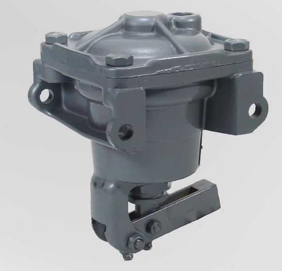
42 42 Pneumatic Marine Products for Propulsion Control AVENTICS Corporation Associated Components Relayair Valve, Type H & L : Pilot operated sequence valves "H" and "L" Relayair Valves Type Supply Pressure Control Pressure Temperature range Media Port Size: Pilot operated sequence valve 200 PSI Max. 140 psi max. -40 F to 160 F Air or inert gas Control port (port 10), breather port (port 1): All other ports: 1/4" NPT 3/8" NPT Operating Characteristics The Relayair Valve has three basic uses: 1. As a nongraduated relay to provide a large flow of air from a separate source when piloted by small amount of control media and to stop this flow and exhaust the air to atmosphere when the control pressure is vented. 2. As an interlock to govern the flow in one circuit by placing its control in another independent circuit. 3. As a pressure-sensitive sequence valve for such circuit functions as timing, cycling, etc. Application Notes RELAYAIR Valves operated by pilot pressures less than 35 psi utilize one control spring while valves operated by pilot pressures greater than 35 psi use two springs. To obtain pilot pressures less than 10 psi, two diaphragms are used in series.
43 Pneumatic Marine Products for Propulsion Control AVENTICS Corporation 43 Associated Components Relayair Valve, Type H & L : Pilot operated sequence valves H-5 Relayair Valve Dimensions * Nameplate location. 9 = Exhaust 10 = Pilot 11 = Delivery 12 = Supply H-5 Relay Dimensions A 1) B C D - NPTF E F G H I - NPTF J K L M 13/16 4-3/8 1/2 1/ /16 1-7/8 9/32 7-3/4 3/ /16 3/16 27/32 1/4 N - NPT O P Q R S T 2) U (3 places) V W X Y Z 1/ /8 7-3/8 7/16 9/16 4-3/8 13/16 13/32 7/16 2 7/16 3-1/2 1-3/4 1) H-5 shown. "A" for H-5-D = 1/8"; for L-2-A = 5/16". 2) Clearance required for removal. * Nameplate location.


44 44 Pneumatic Marine Products for Propulsion Control AVENTICS Corporation Associated Components Three-Position Cylinder, Spring centered Reassemble the cylinder, using the exploded and assembly views as reference. No special tools are required. To avoid cutting or nicking the piston O-ring, carefully insert the piston rod assembly into the cylinder bore with the piston tilted at a slight angle. As the assembly proceeds, lubricate all O- rings with Dow Corning 55M grease. Max. operating pressure: 150 psi (10.3 bar) Temperature range: -40 F to 180 F (-40 C to 82 C)
45 Pneumatic Marine Products for Propulsion Control AVENTICS Corporation 45 Associated Components Three-Position Cylinder, Spring Centered Part No. Old Part No. Stroke* R P R P R P R P R P R P R P R P R P R P *Effective stroke each side of center. Repair kit part no. R (old part no. P K0000)
 Description Part No. Old Part No.")
 Less Access.-w/Drain Hole R431005745 P -061289-00010 10-60 (0.69-4.14) Less Accessories R431004009 P -057159-00010 10-60 (0.")
 With Accessories R431004529 P -058430-00011 35-90 (2.41-6.")
 With Accessories R431003984 P -057086-00011 Force rating: 410 in.-lb. degrees (46.")
 Weight: 3 lbs. (1.")
 Operating lever kit, part no.")
46 46 Pneumatic Marine Products for Propulsion Control AVENTICS Corporation Associated Components A-2-H Actuator Pressure Range psi (bar) Description Part No. Old Part No ( ) Less Accessories R P ( ) With Accessories R P ( ) Less Access.-w/Drain Hole R P ( ) Less Accessories R P ( ) With Accessories R P ( ) With Ball Joint Kit R P ( ) With Accessories R P ( ) Less Accessories R P ( ) With Accessories R P Force rating: 410 in.-lb. degrees (46.3 Nm) Nominal stroke: 2 (50.8 mm), adjustable from 1 7/8 to 2 1/4 (47.63 to mm) Weight: 3 lbs. (1.36 kg) Integral mounting lugs make installation simple and clean Accessory kit, part no. R (Old part no. P ) Operating lever kit, part no. R (Old part no. P )

 AA-1, 1/4 rod eye R431005436 P -060263-00001 8 (3.")
 AA-1, 3/8 rod eye R431005438 P -060263-00003 8.")

 Output travel adjustment: from 7/8 to 2 1/4 (22.")
47 Pneumatic Marine Products for Propulsion Control AVENTICS Corporation 47 Associated Components AA-1 Actuator Description Part No. Old Part No. Weight lbs. (kg) AA-1, 1/4 rod eye R P (3.63) AA-1, 5/16 rod eye R P (3.86) AA-1, 3/8 rod eye R P (3.86) Type: diaphragm-lever actuator, single direction Force rating: 1125 in.-lb. degrees (127.1 Nm) Pressure range: 10 to 60 psi (0.69 to 4.14 bar) Output travel adjustment: from 7/8 to 2 1/4 (22.23 to mm) Weight: 3 lbs. (1.36 kg)
 The Shuttle Valve Panel is designed to mount as a single unit the three Shuttle Valves required for interconnecting two single engine control")
48 48 Pneumatic Marine Products for Propulsion Control AVENTICS Corporation Associated Components Shuttle Valve Panel: Two Station, Single Engine Shuttle Valve Panel Two Station, Single Engine Part Number R (Old Part Number P ) The Shuttle Valve Panel is designed to mount as a single unit the three Shuttle Valves required for interconnecting two single engine control stations to simplify shipboard control system installations. Standard ¼ NPT Shuttle Valves part number R as covered by sales catalog SC-400 and service bulletin SM are utilized. All operation and maintenance conditions and procedures covered in these publications should be observed. R
49 Pneumatic Marine Products for Propulsion Control AVENTICS Corporation 49 Associated Components Shuttle Valve Panel: Two Station, Single Engine Outline View Two Station - Single Engine Shuttle Valve Panel Weight 3.5 lbs (1.6 kg) (Dimensions in inches) Parts List: R (Complete Panel) Ref. No. Qty. Description Part No. Old Part No. 1 3 Shuttle Valve R P Screws, ¼-20 R P Washer, ¼ Lock R P Panel R P


50 50 Pneumatic Marine Products for Propulsion Control AVENTICS Corporation Associated Components Shuttle Valve Panel: Two Station, Twin Engine Shuttle Valve Panel Two Station, Twin Engine Part Number R (Old Part No. P ) The Shuttle Valve Panel is designed to mount as a single unit the six Shuttle Valves required for interconnecting two twin engine control stations to simplify shipboard control system installations. Standard ¼ NPT Shuttle Valves part number R as covered by sales catalog SC-400 and service bulletin SM are utilized. All operation and maintenance conditions and procedures covered in these publications should be observed. R
51 Pneumatic Marine Products for Propulsion Control AVENTICS Corporation 51 Associated Components Shuttle Valve Panel: Two Station, Twin Engine Outline View Two Station - Twin Engine Shuttle Valve Panel Weight 7 lbs (3.2 kg) (Dimensions in inches) Parts List: R (Complete Panel) Ref. No. Qty. Description Part No. Old Part No. 1 1 Panel R P Shuttle Valve, ¼" NPTF R P Screws, ¼ - 20 R P Washer, ¼ Lock R P
 This panel includes the necessary valving mounted as a single unit to provide for attendance interlocked control transfer between the")
52 52 Pneumatic Marine Products for Propulsion Control AVENTICS Corporation Associated Components Control Station Transfer Panel Control Station Transfer Panel for Two Stations Attendance Interlock Function Part Number R (Old Part Number P ) This panel includes the necessary valving mounted as a single unit to provide for attendance interlocked control transfer between the engine room and the above deck control stations. The operation insures that control can not be transferred to the above deck stations unless an operator is in attendance at the receiving station to operate an acknowledge valve and complete the transfer sequence. This insures that control is not inadvertently transferred to an unattended station where the engine control handles may have been left in the operating range. It is the operator s responsibility to check the control handle positions before acknowledging and completing the control transfer operation. (See page 50 for dimensions.) R R R
53 Pneumatic Marine Products for Propulsion Control AVENTICS Corporation 53 Associated Components Control Station Transfer Panel R Weight 18 3/4 lbs (8.5 kg) (Dimensions in inches)


 and Voith-Schneider propellers.")
 that is highly customizable.")


54 54 Pneumatic Marine Products for Propulsion Control AVENTICS Corporation Electronic Marine Controls Overview In addition, to pneumatic marine controls, AVENTICS has been manufacturing electronic marine controls for many years. The Marex OSIII, our most recent control platform, improves upon its predecessors with a compact design, integrated I/O, and expanded propulsion control capabilities. With minor software variations, Marex OS III can be used for remote control and monitoring of propulsion plants with; reversing gear, controllable pitch (CP) and Voith-Schneider propellers. The Marex OSIII has at is heart, a Marine Propulsion Controller (MPC) that is highly customizable. The MPC gives new meaning to control with full programmability of all time delays, speed curves, trolling, engine synchronization, controlled clutch slip, fault diagnostics and easy integration with auxiliary devices/sensors. Our electronic controls are our "Open System", employing CAN-bus protocol; allowing maintenance free networking and fault monitoring of quick connect, modular, components. Our electronic controls are growing increasingly popular with OEMs and also those who are retrofitting ships with older pneumatic technology. An obvious cost benefit of a network interface is its ease in expandability and upgradeability without the need for total system re-wiring. Type 230 controls Type 240 controls Type 250 remote control MPC - Marine Propulsion Controller Electric actuator
55 NOTICE TO PRODUCT USERS 1. WARNING: FLUID MEDIA AVENTICS pneumatic devices are designed and tested for use with filtered, clean, dry, chemical free air at pressures and temperatures within the specified limits of the device. For use with media other than air or for human life support systems, AVENTICS must be consulted. Hydraulic cylinders are designed for operation with filtered, clean, petroleum based hydraulic fluid; operation using fire-resistant or other special types of fluids may require special packing and seals. Consult the factory. 2. WARNING: MATERIAL COMPATIBILITY Damage to product seals or other parts caused by the use of noncompatible lubricants, oil additives or synthetic lubricants in the air system compressor or line lubrication devices voids the AVENTICS warranty and can result in product failure or other malfunction. See lubrication recommendations below. AIR LINE LUBRICANTS! In service higher than 18 cycles per minute or with continuous flow of air through the device, an air line lubricator is recommended.* (Do not use line lubrication with vacuum products.) However, the lubricator must be maintained since the oil will wash out the grease, and lack of lubrication will greatly shorten the life expectancy. The oils used in the lubricator must be compatible with the elastomers in the device. The elastomers are normally BUNA-N, NEOPRENE, VITON, SILICONE and HYTREL. AVENTICS recommends the use of only petroleum based oils without synthetic additives, and with an aniline point between 180 F and 210 F. COMPRESSOR LUBRICANTS! All compressors (with the exception of special "oil free" units) pass oil mist or vapor from the internal crankcase lubricating system through to the compressed air. Since even small amounts of non-compatible lubricants can cause severe seal deterioration (which could result in component and system failure) special care should be taken in selecting compatible compressor lubricants. 3. WARNING: INSTALLATION AND MOUNTING The user of these devices must conform to all applicable electrical, mechanical, piping and other codes in the installation, operation or repair of these devices. INSTALLATION! Do not attempt to install, operate or repair these devices without proper training in the technique of working on pneumatic or hydraulic systems and devices, unless under trained supervision. Compressed air and hydraulic systems contain high levels of stored energy. Do not attempt to connect, disconnect or repair these products when a system is under pressure. Always exhaust or drain the pressure from a system before performing any service work. Failure to do so can result in serious personal injury. MOUNTING! Devices should be mounted and positioned in such a manner that they cannot be accidentally operated. 4. WARNING: APPLICATION AND USE OF PRODUCTS The possibility does exist for any device or accessory to fail to operate properly through misuse, wear or malfunction. The user must consider these possibilities and should provide appropriate safe guards in the application or system design to prevent personal injury or property damage in the event of a malfunction. 5. WARNING: CONVERSION, MAINTENANCE AND REPAIR When a device is disassembled for conversion to a different configuration, maintenance or repair, the device must be tested for leakage and proper operation after being reassembled and prior to installation. MAINTENANCE AND REPAIR! Maintenance periods should be scheduled in accordance with frequency of use and working conditions. All AVENTICS products should provide a minimum of 1,000,000 cycles of maintenance free service when used and lubricated as recommended. However, these products should be visually inspected for defects and given an "in system" operating performance and leakage test once a year. Where devices require a major repair as a result of the one million cycles, one year, or routine inspection, the device must be disassembled, cleaned, inspected, parts replaced as required, rebuilt and tested for leakage and proper operation prior to installation. See individual catalogs for specific cycle life estimates. 6. PRODUCT CHANGES Product changes including specifications, features, designs and availability are subject to change at any time without notice. For critical dimensions or specifications, contact factory. *Many AVENTICS pneumatic valves and cylinders can operate with or without air line lubrication; see individual sales catalogs for details. -Refer to the appropriate service manual for parts and service information, most are available for download from LIMITATIONS OF WARRANTIES & REMEDIES AVENTICS warrants all Products manufactured by it to be free from defects in material and workmanship under normal operating conditions and proper application in accordance with specifications for operation as described in the Data Sheet which accompanies such Products, for (i) twenty-four (24) months after date of shipment to Distributor, (ii) eighteen (18) months after date of shipment to the customer, or (iii) twelve (12) months after the Product is placed in service, whichever occurs first. Vendor or customer-supplied items on systems, assemblies are warranted per original manufacturer s warranty policy. THE FOREGOING WARRANTY IS EXPRESSLY IN LIEU OF ANY OTHER WARRANTIES EXPRESSED OR IMPLIED, INCLUDING BUT NOT LIMITED TO THE IMPLIED WARRANTIES OF MERCHANTABILITY OR FITNESS FOR A PARTICULAR PURPOSE. Buyer s sole and exclusive remedy under this warranty shall be limited to the repair or exchange of warranted products at AVENTICS option FOB AVENTICS factory. No attempt to repair or improve the Goods or parts by any of AVENTICS representatives shall change or extend this warranty. If the Buyer (as that term is hereafter defined) or Agent grants to an end user any warranty which is greater in scope, time period or labor allowance than the warranty stated herein, AVENTICS shall not be liable beyond this stated warranty. Except as otherwise provided under the Warranty Processing Procedures section of this warranty, equipment and accessories not manufactured by AVENTICS shall not be the responsibility of AVENTICS. The term Buyer as used herein means the person or firm that purchased the product directly from AVENTICS, and includes direct OEM customers and AVENTICS distributors. No products shall be returned without prior authorization from AVENTICS. Buyer shall prepay all transportation charges for the return of such products to AVENTICS factory or authorized factory service center. AVENTICS will not accept any charges for labor and/or parts incidental to the removal and remounting of products repaired or replaced under this warranty. All repair and replacement parts provided under this warranty will assume the identity, for warranty purposes, of the part replaced and the warranty on such replacement parts will expire when the warranty on the original part would have expired. Claims must be submitted within 30 days of failure or be subject to rejection. This warranty is not transferable beyond the first using purchaser. An AVENTICS Quality Service Report (QSR) to initiate the warranty request is available online ( Additonal conditions apply - for full details, download our Terms & Conditions of Sale from

56 AVENTICS Corporation 1953 Mercer Road Lexington, KY Tel Fax AVENTICS Incorporated 5515 North Service Rd Suite #100 Burlington, Ontario L7L 6A6 Tel Fax AVENTICS México, S. de R.L. de C.V. AV. Paseo de la Reforma 250, Esquina Niza Deleg. Cuauhtémoc México, D.F. Tel Further contacts: The data specified only serve to describe the product. No statements concerning a certain condition or suitability for a certain application can be derived from our information. The information given does not release the user from the obligation of own judgment and verification. It must be remembered that our products are subject to a natural process of wear and aging. SC Online version. Subject to change. Printed in USA. AVENTICS Corporation This document, as well as the data, specifications and other information set forth in it, are the exclusive property of AVENTICS. It may not be reproduced or given to third parties without its consent.
HD-2 CONTROLAIR VALVE
 HD-2 CONTROLAIR VALVE Service Information Description of Models The HD-2 Type Controlair Valves are handle operated 4-way, exhausted center, pressure control valves. The typical unit contains two directional
LOGIC VALVE DISASSEMBLY AND SERVICE REPAIR PROCEDURE
 LOGIC VALVE DISASSEMBLY AND SERVICE REPAIR PROCEDURE Service Information WARNING - INSTALLATION AND MOUNTING The user of these devices must conform to all applicable electrical, mechanical, piping and
Mini 1. Compact High Flow 3-Way and 4-Way Pneumatic Directional Control Valves
 Catalog LX-530 Mini 1 Compact High Flow and Pneumatic Directional Control Valves FEATURES: 3-port or 5-port bodies Manual, Air Pilot, Solenoid or Mechanical Operators Two-position, Single or Dual Actuation
Pneumatic AD System Manual 11-07
 Pneumatic AD2-5000 System Manual -07 AD2-5000 Table of Contents System Explanation... Drawing 3732- Station and Station 2 Configuration...6 Drawing 3732-2 Engine Room Configuration...8 S-46 Rev.E 2/0...0
PNEUMATIC PIPING DEVICES Service Information
 PNEUMATIC PIPING DEVICES Service Information PRODUCT DESCRIPTION PAGE Quick Exhaust Valves (Quick Release Valves)................................... 2-3 1/4, 3/8, 1/2, 3/4 & 1 pipe sizes, diaphragm type,
Marine Technology Pneumatics
 Marine Technology Pneumatics for MARINE applications Aventics Marine Applications Pneumatics Ship Controls Valve Control Systems Selective Catalytic Reduction (SCR) Control of two-stroke engines Control
H-1 & H-1-A CONTROLAIR VALVE
 H- & H--A CONTROLAIR VALVE Service Information DESCRIPTION OF MODELS The H- and H--A Type CONTROLAIR Valves are spring returned pedal actuated 3-way pressure graduating valves. A pedal actuates the valve
Types 472, 473, 3572, 3573
 Instruction Manual Form 1844 May 1998 Types 472, 473, 3572, 3573 Types 472, 473, 3572, 3573 Contents Introduction.............................. 2 Scope of Manual............................. 2 Type Number
Powers Controls RL 147 Positioning Relay
 Powers Controls Technical Instructions Document No. 155-038P25 RL 147-2 Description Features Rapid response Product Numbers See Table 1. The is a compact, pneumatic device designed to provide positive
ANDERSON GREENWOOD SERIES 500 PILOT OPERATED SAFETY RELIEF VALVES INSTALLATION AND MAINTENANCE INSTRUCTIONS
 Before installation these instructions must be fully read and understood TABLE OF CONTENTS 1. General valve description and start-up... 1 2. Main valve maintenance... 1 3. Pilot maintenance... 5 4. Pilot
INSTALLATION INSTRUCTION MANUAL FOR KOBELT PNEUMATIC SYSTEMS
 INSTALLATION INSTRUCTION MANUAL FOR KOBELT PNEUMATIC SYSTEMS NOTES ON WARRANTY Kobelt Manufacturing provides installation and maintenance instructions for its products. If these guidelines are not followed,
PNEUMATIC CONTROLS. ELECTRONIC C O NTR O Ls
 PNEUMATIC CONTROLS Hydraulic Steering & Accessories ELECTRONIC C O NTR O Ls Push-Pull C O NTR O Ls Disc Brakes for the latest information please visit www.kobelt.com CONTROL YOUR SHIP WITH COMPLETE SYSTEMS
HC-2 CONTROLAIR VALVE
 HC-2 CONTROLAIR VALVE Service Information Description of Models Table of Contents Page Description of Models 1 Warnings 2 Technical Data 2 Installation 2 Maintenance and Repair 2 Outline Dimensions 3 Descriptions
The following valve actuators are compatible with all Clippard MAV, MAVO, MJV, MJVO, ES-1, & FV series valves.
 VALVE ACTUATORS The following valve actuators are compatible with all Clippard MAV, MAVO, MJV, MJVO, ES-1, & FV series valves. One of the most versatile items in the Clippard line. Permits wide circuit
 WINCH OPERATING PRACTICES 1. Read the manufacturer's instructions before operating the winch. 2. Always inspect, test maintain and operate this winch in accordance with American National Standards Institute
Accessories Index. Air Starters. Accessories Index By Description Accessory IR Page Description Part # Number J 1 SRV125 SRV125T SRV100
 Air Starters Accessories Index Accessories Index By Description Accessory IR Page Description Part # Number Relay Valves SRV100 SRV125 SRV125T SRV150 SRV150SS Relay Valve Tune Up Kit SRV150-TK3 J-3 J-4
Adjustable Differential Relay A1
 Sales Manual Section 332 PRODUCT SPECIFICATION MODEL 84871-A1 GENERAL DESCRIPTION The 84871-A1 Adjustable Differential Diverting Relay is a two-position, snap-acting, three-way relay. Its normal function
V-9502 Series Pneumatic Valve Actuator Positioners
 P O S 14-365- 6, Rev. F Installation Instructions V-9502 Issue Date February 2016 V-9502 Series Pneumatic Valve Actuator Positioners Application V-9502 Series Pneumatic Valve Actuator Positioners are precision
Double Acting and Spring Return Direct Gas Quarter-turn Actuators Output Torques to 6,500,000 lb.in.
 Biffi GIG/GIGS Direct Gas Actuators Double Acting and Spring Return Direct Gas Quarter-turn Actuators Output Torques to 6,500,000 lb.in. Features and Benefits Separate gas and hydraulic cylinders prevent
WDV-2 2-way normally closed poppet with air pilot. When valve closes a spring biased internal piston draws back a small volume on outlet side (approx.
 PV-1 MPS-2P SPECIALTY COMPONENTS Miniature pulse valve, a normally open 3-way valve that closes shortly after being pressurized and remains closed until supply pressure is exhausted and repressurized.
Vickers. Overhaul Manual. Vane Pumps. Small and Large Series Combination Pumps VC(K)(S)-**-(*)*D*-6(1) VC(K)(S)-**-(*)-*-*D*-5(1)
(S)-**-(*)*D*-6(1) VC(K)(S)-**-(*)-*-*D*-5(1)") Overhaul Manual Vickers Vane Pumps Small and Large Series Combination Pumps VC(K)(S)-**-(*)*D*-6(1) VC(K)(S)-**-(*)-*-*D*-5(1) Revised 12/1/86 I-3150-S Table of Contents Section I. Introduction................................................................................
Overhaul Manual Vickers Vane Pumps Small and Large Series Combination Pumps VC(K)(S)-**-(*)*D*-6(1) VC(K)(S)-**-(*)-*-*D*-5(1) Revised 12/1/86 I-3150-S Table of Contents Section I. Introduction................................................................................
CH.4 Basic Components of Hydraulic and Pneumatic System/16 M HAP/17522/AE5G
 Content : 4.1 Hydraulic and Pneumatic actuators. 10 Marks Hydraulic Actuators - Hydraulic cylinders (single, double acting and telescopic) construction and working, Hydraulic motors (gear and piston type)
Fisher 1051 and 1052 Style H and J Sizes 40, 60 and 70 Rotary Actuators
 Instruction Manual 1051 and 1052 H & J Actuators Fisher 1051 and 1052 Style H and J Sizes 40, 60 and 70 Rotary Actuators Contents Introduction... 1 Scope of Manual... 1 Description... 2 Specifications...
Fisher 1061 Pneumatic Piston Rotary Actuator with Style H & J Mounting Adaptations
 Instruction Manual 1061 H & J Actuator Fisher 1061 Pneumatic Piston Rotary Actuator with Style H & J Mounting Adaptations Contents Introduction... 1 Scope of Manual... 1 Description... 2 Specifications...
470 Series Piston Actuators
 January 000 Bulletin 61.:470 470 Series Piston Actuators The 470 Series pneumatic piston actuators (figure 1) are used in either throttling or on-off applications with control valves having 90.5 mm (3-9/16
SD Bendix E-10PR Retarder Control Brake Valve DESCRIPTION. OPERATION - Refer to Figure 2
 SD-03-832 Bendix E-10PR Retarder Control Brake Valve MOUNTING PLATE SUPPLY 4 PORTS ELECTRICAL AUXILIARY DESCRIPTION TREADLE RETARDER CONTROL SECTION EXHAUST DELIVERY 4 PORTS FIGURE 1 - E-10PR RETARDER
CONTROL YOUR SHIP WITH COMPLETE SYSTEMS AND COMPONENTS FROM KOBELT MANUFACTURING
 CONTROL YOUR SHIP WITH COMPLETE SYSTEMS AND COMPONENTS FROM KOBELT MANUFACTURING 1 Steering components up to 320 tonmeter for hydraulic steering of single and multi-rudder vessels 2 In the aftdeck control
Fisher 657 and 667 Diaphragm Actuators
 657 and Actuators Product Bulletin Fisher 657 and Diaphragm Actuators Fisher 657 and spring-opposed diaphragm actuators position the valve plug in the valve in response to varying controller or valve positioner
Model Stroke, Two Handle Push Pull Control Head
 Model 2009 3 Stroke, Two Handle Push Pull Control Head This control is available with three different handles; standard, handles with plastic grips or curved handles with knobs. An optional clutch and
MARINE PROPULSION CONTROL
 COMPONENT BULLETIN SB-1110-1900 MARINE PROPULSION CONTROL PNEUMATIC LOGIC AND CONTROL PANEL Control Panel APPLICATION Propulsion controls for small and large vessels with fixed pitch propellers, reversing
Valtek Auxiliary Handwheels and Limit Stops
 Valtek Auxiliary s and Limit Stops Table of Contents Page 1 General information 2 Installation 2 Side-mounted handwheels, size 25 and 50 (linear actuators) 3 Side-mounted handwheels, size 100 and 200 (linear
Anderson Greenwood Series 400 Piston Pilot POPRV Installation and Maintenance Instructions
 Before installation these instructions must be fully read and understood As capacity relief of the system is satisfied, system pressure will begin to decrease. When it does, the pilot will actuate and
Torqueflite Trans-Scat Kit
 TCI 220000 Torqueflite Trans-Scat Kit This kit can be installed in a few hours by carefully following directions. Read all instructions first to familiarize yourself with the parts and procedures. Work
Series 810: 2 Way Angle Body Valves: 1/4 to 3 NPT
 Series 810: 2 Way Angle Body Valves: 1/4 to 3 NPT FEATURES Compact design, high fl ow rates Visual position indicator standard For temperatures from 22 F to +430 F / -30 C to 221 C Working pressures up
Double Acting & Spring Return. SERIES 92/93 Rack & Pinion PNEUMATIC ACTUATOR. The High Performance Company
 PNEUMATIC ACTUATOR SERIES 92/93 Rack & Pinion Double Acting & Spring Return The High Performance Company SERIES 92/93 Styling, strength, compactness, and simplicity of design have been combined to produce
CONTROL VALVES. Installation, Maintenance & Operating Instructions. Read these instructions carefully before installation or servicing.
 KOSO HAMMEL DAHL CONTROL VALVES KOSO HAMMEL DAHL 253 Pleasant Street West Bridgewater, MA 02379 tel: 774.517.5300 fax: 774.517.5230 www.hammeldahl.com Installation, Maintenance & Operating Instructions
Fisher 657 Diaphragm Actuator Sizes and 87
 Instruction Manual 657 Actuator (30-70 and 87) Fisher 657 Diaphragm Actuator Sizes 30 70 and 87 Contents Introduction... 1 Scope of Manual... 1 Description... 2 Specifications... 2 Installation... 3 Mounting
Flowrite AP 599 Series
 AP 599-2 Flowrite AP 599 Series 12-inch Pneumatic Valve Actuator Description The Flowrite AP 599 Series 12-inch pneumatic valve actuator is designed for use with the Flowrite VF 599 Series valves. This
Table of Contents. Proportional & Precision Regulator Instrumentation
 Table of Contents Proportional & Precision Regulator Instrumentation...3-27 Features and Benefits... 3 Electropneumatic Transducer...4-5 Economy Miniature Electropneumatic Transducer...6-7 Miniature Electropneumatic
SERIES Waterman* DESCRIPTION FLOW PRESSURE PAGE NO.
 Contents SERIES Waterman* DESCRIPTION FLOW PRESSURE PAGE NO. NVH081...12CNVH1...Needle Valve...10 GPM... 5500 PSI... FC5-FC6 NVH101...15CNVH1...Needle Valve...16 GPM... 5500 PSI... FC7-FC8 NV162...21CNV2...Needle
Service and Parts Manual. Minimum Filtration Required:
 R GRESEN Hydraulics Model V0 Sectional Body Directional Control Valve Service and Parts Manual Maximum Operating Pressure: Minimum Filtration Required: 00 PSI ( bar) 0 Micron The information in this Service
Fisher 2052 Diaphragm Rotary Actuator
 Instruction Manual 2052 Actuator Fisher 2052 Diaphragm Rotary Actuator Contents Introduction... 1 Scope of Manual... 1 Description... 1 Specifications... 4 Installation... 4 Actuator Mounting and Changing
OPERATION AND PARTS MANUAL
 OPERATION AND PARTS MANUAL MODEL NUMBER : PART NUMBER : TAP- IN KIT 5100-5151 BAYNE MACHINE WORKS, INC. PHONE: (864) 288-3877 910 FORK SHOALS ROAD TOLL FREE: (800) 535-2671 GREENVILLE S.C., 29605 FAX:
SERIES 8100 HAND-OPERATED PRESSURE CALIBRATION UNITS
 SERIES 8100 HAND-OPERATED PRESSURE CALIBRATION UNITS PORTABLE PRESSURE SOURCE USED WITH A PRESSURE GAUGE TO FIELD CALIBRATE A VARIETY OF PRESSURE DEVICES, i.e., PRESSURE SWITCHES, GAUGES, DIFFERENTIAL
Fisher 3024C Diaphragm Actuator
 Instruction Manual 3024C Actuator Fisher 3024C Diaphragm Actuator Contents Introduction... 1 Scope of Manual... 1 Description... 2 Specifications... 3 Installation... 5 Mounting the Actuator on the Valve...
Welker Sampler. Installation, Operation, & Maintenance Manual. Model GSS-4HP
 Installation, Operation, & Maintenance Manual Welker Sampler Model GSS-4HP The information in this manual has been carefully checked for accuracy and is intended to be used as a guide to operations. Correct
Transmitters: Relay Valve VR4151/4152
 Relay Valve VR4151/4152 Appropriate output sequences are affected according to the signal received from the mechanical valve. VR4151 VR4152 Precautions Be sure to read before handling. Refer to pages 5-11-2
CVS Type 667 Diaphragm Actuator Sizes 30-70
 Instruction Manual CVS Type 667 Diaphragm Actuator Sizes 30-70 All CVS Controls actuators are to be installed and maintained in accordance with instructions supplied by CVS Controls. This manual includes
SINGLE LEVER TOP MOUNT CONTROLS
 SINGLE LEVER 20 Single lever / dual action control to operate both throttle and shift. Suitable for any type of boats with outboard, inboard or I/O power plants. SINGLE LEVER Enables easy and safe shifting
Flowrite TM AP 599 Series 8-inch Pneumatic Valve Actuator
 Flowrite TM AP 599 Series 8-inch Pneumatic Valve Actuator Technical Instructions Document No. 155-161P25 AP 599-1 Description Features Application The Flowrite AP 599 Series 8-inch pneumatic valve actuator
REPAIR PROCEDURES MANUAL
 REPAIR PROCEDURES MANUAL PVX Series Vane Pumps A Design Series Step-by-Step Guide to Troubleshooting and Repairing PVX Series Vane Pumps Introduction Thank you for choosing Continental Hydraulics PVX Vane
GH-BETTIS SERVICE INSTRUCTIONS DISASSEMBLY & REASSEMBLY FOR MODELS HD521-M4, HD721-M4 AND HD731-M4 DOUBLE ACTING SERIES PNEUMATIC ACTUATORS
 GH-BETTIS SERVICE INSTRUCTIONS DISASSEMBLY & REASSEMBLY FOR MODELS HD521-M4, HD721-M4 AND HD731-M4 DOUBLE ACTING SERIES PNEUMATIC ACTUATORS WITH HYDRAULIC CONTROL PACKAGE PART NUMBER: SE-023 REVISION:
Control Valves Positioner
 Control Valves Positioner HiFlo Valve Positioner Easy calibration Corrosion-resistant cover and base Withstands 150 psi at all parts Two -sided cam for easy field reversibility Optional / NPT for piped
Control Valves Positioner
 Control Valves Positioner HiFlo HiFlo Valve Positioner Corrosion-resistant cover and base Easy calibration Withstands 150 psi at all parts Two -sided cam for easy field reversibility Optional / NPT for
TECHNICAL PAPER 1002 FT. WORTH, TEXAS REPORT X ORDER
 I. REFERENCE: 1 30 [1] Snow Engineering Co. Drawing 80504 Sheet 21, Hydraulic Schematic [2] Snow Engineering Co. Drawing 60445, Sheet 21 Control Logic Flow Chart [3] Snow Engineering Co. Drawing 80577,
Flare Valves 1/2 inch 2-Way and 3-Way
 Valve and Actuator Manual 977 Valve Product Information Section Product Bulletin VTF Series Issue Date 0596 Flare Valves 1/2 inch 2-Way and 3-Way The 1/2 inch flared valve line is designed to accurately
Fisher 585C Series Piston Actuators
 Instruction Manual D102087012 585C Actuator Fisher 585C Series Piston Actuators Contents Introduction... 1 Scope of Manual... 1 Description... 2 Specifications... 2 Educational Services... 2 Principle
Versa exercises diligence to assure that information contained in this catalog is correct, but does not accept responsibility for any errors or omissi
 SERIES B VALVES AIR VALVES FOR INDUSTRY SINCE 1949 ISO 9001 Two-Way Types for bleeding pilots of larger valves, for bleeding cylinders or small pressure systems, operating air tools or motors, opening
CONTROL YOUR SHIP WITH COMPLETE SYSTEMS AND COMPONENTS FROM KOBELT MANUFACTURING
 P U S H - P U L L C O N T R O L S H Y D R A U L I C S T E E R I N G & A C C E S S O R I E S E L E C T R O N I C C O N T R O L S P N E U M A T I C C O N T R O L S D I S C B R A K E S F O R T H E L A T E
Port Flow Rate/ Function Series Actuators Page Number Size Factor
 Section dex Port Flow Rate/ Function Series Actuators Page Number Size Factor 0- Cv = 0.05 Way Modular Solenoid. -. & to Way Manifold /8 NPT Cv = 0. Way, Position Modular /8 NPT Cv = 0.05 Way Hex Solenoid.5.6
Logic elements. Differential pressure sensing elements for applications up to 350 bar (5000 psi) and 400 L/min (100 USgpm)
 and 400 L/min (100 USgpm)") Hydraulic Screw-in Cartridge Valves (SiCV) Logic elements Differential pressure sensing elements for applications up to 50 bar (5000 psi) and 400 L/min (00 USgpm) Logic elements LOGC ELEMENTS... -4 APPLCATON
Hydraulic Screw-in Cartridge Valves (SiCV) Logic elements Differential pressure sensing elements for applications up to 50 bar (5000 psi) and 400 L/min (00 USgpm) Logic elements LOGC ELEMENTS... -4 APPLCATON
MARINE PROPULSION CONTROL
 PRODUCT BULLETIN SB-8504B MARINE PROPULSION CONTROL ELECTRONIC LOGIC AND CONTROL PANEL Type MPC-E9 Control Panel APPLICATION Propulsion controls for small and large vessels with fixed pitch propellers,
CVS Type 657 Diaphragm Actuator Sizes 30-70
 Instruction Manual CVS Type 657 Diaphragm Actuator Sizes 30-70 All CVS Controls equipment, including actuators, are to be installed and maintained in accordance with instructions supplied by CVS Controls.
Type 644 and 645 Differential Pressure Pump Governors
 Instruction Manual 644 and 645 Pump Governors Type 644 and 645 Differential Pressure Pump Governors Introduction Scope of Manual This instruction manual provides information on installation, adjustment,
Fisher 585C Series Piston Actuators
 Instruction Manual D102087012 585C Actuator Fisher 585C Series Piston Actuators Contents Introduction............................... 1 Scope of Manual.......................... 1 Description...............................
THD-2-FM CONTROLAIR VALVE
 THD-2-FM CONTROLAIR VALVE PART NO. S R431000720 ( Part No. P -027121-00101) R431000721 ( Part No. P -027121-00109) SERVICE INFORMATION DESCRIPTION The THD-2-FM CONTROLAIR Valve, designed for marine service,
Type 1051 and 1052 Diaphragm Rotary Actuators
 Product Bulletin 1051 and 1052 Actuators Type 1051 and 1052 Diaphragm Rotary Actuators The Type 1051 and 1052 spring-return diaphragm rotary actuators (figure 1) operate splined shaft rotary valves, such
Pilot-Operated Regulators
 Fisher Controls Instruction Manual Type 1098-EGR & 1098H-EGR Pilot-Operated Regulators R May 1987 Form 5084 Contents Introduction................................... 2 Scope of Manual..............................
3000 psi (207 bar) Output/ min. 115 VAC 10cc (0.61 cu. in.) 24 VDC 12cc (0.73 cu. in.) Discharge Element Output Port.
 Output/ min. 115 VAC 10cc (0.61 cu. in.) 24 VDC 12cc (0.73 cu. in.) Discharge Element Output Port.") MultiPort Lubricator Grease, Injector General The MultiPort Lubricator is an electrically driven multiple outlet lubrication unit design primarily for use with injector systems. The unit includes two pumping
MultiPort Lubricator Grease, Injector General The MultiPort Lubricator is an electrically driven multiple outlet lubrication unit design primarily for use with injector systems. The unit includes two pumping
AUTOMATIC TRANSMISSIONS Mitsubishi F3A20 Series TRANSMISSION APPLICATION TABLE
 Article Text ARTICLE BEGINNING AUTOMATIC TRANSMISSIONS Mitsubishi F3A20 Series APPLICATION TRANSMISSION APPLICATION TABLE Vehicle Application Transmission Model Colt 3-Speed (1990-94)... F3A21 Colt Vista
SP-20 Input. Installation and Operating Instructions Electro-Pneumatic Linear Positioner. Description of Device. Part Number System
 Description of Device VALMAC Posi-Zest SP-2000 Series is the advanced control device for a linear control valve that provides unparalleled stability in difficult environments. Easy maintenance Precise
Type 1051 and 1052 Size 33 Diaphragm Rotary Actuator
 Instruction Manual Type 1051 and 1052 Size 33 Diaphragm Rotary Actuator 1051 & 1052 Actuator Contents Introduction............................. 1 Scope of Manual........................... 1 Description................................
Sinclair Collins. Process Control Valves. For Steam, Hot and Cold Liquids -40 to 450 F up to 500 psi. Catalog SCV-100/USA April 2001
 Sinclair Collins Process Control Valves For Steam, Hot and Cold Liquids -40 to 450 F up to 500 psi April 2001 The Diaphragm Operated Valves on the following pages are designed for directing, diverting
AF0465-XX SERVICE KITS GENERAL DESCRIPTION MODEL DESCRIPTION CHART OPERATING AND SAFETY PRECAUTIONS THIS MANUAL COVERS THE FOLLOWING MODELS
 OPERATOR S MANUAL INCLUDING: SERVICE KITS, TROUBLESHOOTING, PARTS LIST, DISASSEMBLY & REASSEMBLY. 4-1/4 AIR MOTORS AF044X-XX (4 STROKE) and AF046X-XX (6 STROKE) Also covers 637489 service kits AF044X-XX
Clippard offers more types of miniature pneumatic cylinders for the MINIMATIC CYLINDER
 MINIMATIC CYLINDER Clippard offers more types of miniature pneumatic cylinders for the designer s convenience, including: spring return, spring extend, air retract, double-acting and double rod models.
OPERATING INSTRUCTIONS & SERVICE MANUAL BLUE MAX II HYDROSTATIC TEST PUMP
 PAGE 1 OF 10 OPERATING INSTRUCTIONS & SERVICE MANUAL BLUE MAX II HYDROSTATIC TEST PUMP EFFICIENT, EASY OPERATION Air operated pump Wide range of pressures and volumes Easy to operate controls Output pressure
SINGLE LEVER TOP MOUNT CONTROLS
 SINGLE LEVER TOP MOUNT CONTROLS 20 Single lever / dual action control to operate both throttle and shift. Suitable for any type of boats with outboard, inboard or I/O power plants. SINGLE LEVER TOP MOUNT
Installation and Operating Instructions Electro-Pneumatic Rotary Positioner SP-21. Description of Device. Part Number System
 Description of Device VALMAC Posi-Zest SP-2100 Series is the advanced control device for a rotary control valve that provides unparalleled stability in difficult environments. Easy Maintenance Precise
Fisher 2506 and 2516 Receiver Controllers
 2506/2516 Receiver Controllers Product Bulletin Fisher 2506 and 2516 Receiver Controllers The 2506 receiver controller takes the input from a pneumatic transmitter, matches it against the adjustable set
Caliper Disc Brakes. Description H-1. Technical Data and Selection Procedure H DP100 Caliper H-4. HC3 and HD3 Calipers H-7
 Eaton Corporation Airflex Division 9919 Clinton Road Cleveland, Ohio 44144-1077 Caliper Disc Brakes H Phone (216) 281-2211 Fax: (216) 281-3890 Description H-1 Technical Data and Selection Procedure H-2
235/245400, , 28N
 Models 235/245400, 287000, 28N thru W, 310/312/313700 These carburetors have a fixed high speed main jet with adjustable idle, Fig 183. The different carburetors are identified as LMT 1 and up. The letters
GH-BETTIS OPERATING & MAINTENANCE INSTRUCTIONS DISASSEMBLY & ASSEMBLY FOR THE T80X-M4-S DOUBLE ACTING SERIES HYDRAULIC ACTUATORS
 GH-BETTIS OPERATING & MAINTENANCE INSTRUCTIONS DISASSEMBLY & ASSEMBLY FOR THE T80X-M4-S DOUBLE ACTING SERIES HYDRAULIC ACTUATORS -S INDICATES CYLINDERS ARE IN TANDEM PART NUMBER: 100121 REVISION "A" ECN
Forbes Marshall Pneumatic Actuator. Series MSP and SSP
 Forbes Marshall Pneumatic Series MSP and SSP Multi Spring (MSP Series) Forbes Marshall Pneumatic Diaphragm Protective cap housing Spring Diaphragm plate Diaphragm O ring spindle Yoke Stroke scanning lever
Moniteur INSTALLATION & OPERATING INSTRUCTIONS. SERIES 40 Positioners. Installation and Operating Instructions Series 40 Positioners.
 INSTALLATION & OPERATING INSTRUCTIONS SERIES 40 Positioners Form IO2-0406 Description of Device Moniteur's Series 40 pneumatic (3-15psi) and electropneumatic (4-20mA) positioners are advanced control devices
1 Pneumatics. Transmitters VR4151 VR4152 VR1210 VR1220 VR1210F VR1220F VR1211F VR VR3200 VR3201 VR3100 VR3110
 Best 1 Pneumatics Transmitters Relay valve P. 1900 Side piping: 30 x 53 x 91 Bottom piping: 30 x 8 x 91 VR151 VR152 Effective area (mm 2 ) Number of ports Function 7 5 Metal Spool Shuttle valve P. 1902
Illustrated Parts List to
 TYPE NUMBERS 0101, 0102, 0106, 0108, 0109, 0115 through 0224, 0415, 0418, 0467, 0468, 0601 through 0683, 3101 through 3108, 3110 through 3163, 3167 through 3181. Illustrated Parts List Model Series 124700
200C II BRAKE SYSTEM
 200C II BRAKE SYSTEM The braking system on the 200C II Kress Coal Hauler uses hydraulic oil pressure from both the System and Steering accumulator circuits. Using oil from both circuits provides braking
Precision Control Devices
 Precision Control Devices Electro-Pneumatic Servo Pressure Controllers Electro-Pneumatic I/P, E/P, & P/I Transducers Diaphragm Regulators & Relays Diaphragm Cylinders Filter - Regulator - Lubricators Gauge
SERIES BCS STRETCH ROD CYLINDERS
 BCS y Q ua lit Support SOLUTIONS for the Plastic Bottle Blowing Industry DIRECT REPLACEMENT FOR SIDEL SERIES AND SERIES MACHINES P U O C PACK TI A S y er iv el D ENTS GR N O G COM P IN G SERIES BCS STRETCH
Electro-Pneumatic Linear Positioner Installation and Operation Instructions B GB
 Installation and Operation Instructions 99.66.02-B GB Description of Device (4-~20mA) is the advanced control device for a linear control valve that provides unparalleled stability in difficult environments
SERVICE INSTRUCTIONS D TON
 1120 SOUTH CRYSTAL AVE * BENTON HARBOR MI PH: 269-925-7777 FAX: 269-925-6656 SERVICE INSTRUCTIONS D-51223 4 TON TO ASSEMBLE: 1. Check the handle set screw for tightness. CUSTOMER PRE-USE INSTRUCTIONS THE
SINGLE LEVER TOP MOUNT CONTROLS
 SINGLE LEVER 20 Single lever / dual action control to operate both throttle and shift. Suitable for any type of boats with outboard, inboard or I/O power plants. SINGLE LEVER Enables easy and safe shifting
ANDERSON GREENWOOD SERIES 9290 PILOT OPERATED SAFETY RELIEF VALVES INSTALLATION AND MAINTENANCE INSTRUCTIONS
 Before installation these instructions must be fully read and understood TABLE OF CONTENTS 1 General valve description and instructions... 2 2 Main valve maintenance... 2 3 Pilot maintenance... 12 4 Pilot
Model 3200 Liquid Level Controller
 Model 3200 Liquid Level Controller The Model 3200 Liquid Level Controller is ideal for oilfield scrubber and separator applications. Its rugged and versatile design make it the preferred choice of production
CONTROLS. Bray Pneumatic Actuators & Accessories. Technical Manual. A Division of BRAY INTERNATIONAL, Inc.
 CONTROLS A Division of BRAY INTERNATIONAL, Inc. Bray Pneumatic Actuators & Accessories Technical Manual TM-056 Pneumatic Actuator - 08//00 Bray Pneumatic Actuators & Accessories Technical Manual - Table
User s Manual OM th edition
 FloWing Eccentric Rotary type Control Valves Model: VFR (1, 1½, 2 inches) User s Manual OM2-8130-0300 5th edition Copyright, Notices and Trademarks 2012 Azbil Corporation All Rights Reserved. While this
P99 Pressure Reducing Regulator
 P99 Pressure Reducing Regulator Applications City / District gate operation Commercial buildings Boilers, furnace, oven Plant air service Features 5 Pilot choices for low to extra high pressure Up to 1,000
Input, Control and Processing elements
 PNEUMATIC & HYDRAULIC SYSTEMS CHAPTER FIVE Input, Control and Processing elements Dr. Ibrahim Naimi Valves The function of valves is to control the fluid path or the pressure or the flow rate. Depending
Return to Instruction Sheet index TCI Torqueflite Trans-Scat Kit
 Page 1 of 11 Return to Instruction Sheet index TCI 220000 Torqueflite Trans-Scat Kit This kit can be installed in a few hours by carefully following directions. Read all instructions first to familiarize
980 B Wheel Loader S/n 89P1 & Up Volume 1 of 2
 Caterpillar Service Manual 980 B Wheel Loader S/n 89P1 & Up Volume 1 of 2 Service Manual THIS IS A MANUAL PRODUCED BY JENSALES INC. WITHOUT THE AUTHORIZATION OF CATERPILLAR OR IT S SUCCESSORS. CATERPILLAR