Pneumatic AD System Manual 11-07
|
|
|
- Randell Cross
- 6 years ago
- Views:
Transcription
1 Pneumatic AD System Manual -07
2
3 AD Table of Contents System Explanation... Drawing Station and Station 2 Configuration...6 Drawing Engine Room Configuration...8 S-46 Rev.E 2/0...0 AD2 Air Drive System Operation...2 B5-43 Rev.D 2/ AD2 Air Drive Timing Chart...6 S-7 Rev.C / AD2 Air Drive Valve Movement...20 S-66 Rev.A 2/ AD2 Trouble Shooting Guide...24 Drawing 4768C - AD2 Control Circuit...26 B5-48 Rev.B 2/ AD2 Supply Valve...30 B5-49, Rev.D, 2/ AD2 Speed Interrupt Valve...34 B5-50 Rev.D 2/ AD2 Speed Boost Valve...38 B5-54 Rev.C 2/ Shuttle Valve - Manifolds...42 B4-20 Rev.J 9/ CH5, CH0, CH Series Control Heads...46 B4-9 Rev.C 2/ SP9 Push Button Valve...50 REVISIONS LIST...52 Drawing 6443A SJ8-400 Junction Panel...54 Drawing 5348 TG2 Test Gauge Panel...56 Drawing SV2-350 Service Kit...58 Drawing 8256C - AT-200 Air Treatment Panel...60 Norgren [F74G] Filter...62 Norgren [R74G] Regulator...64 Noshok Gauges...66 Parker Ball Valve...68 Drawing 6242A Test Gauge Panel...70 B5-63 Rev.C 2/ SV2 Spool Valves...74 B5-72 Rev.C 2/ RV8 Relay Valve...78 Drawing 799D SP Selector 80 Page 5
4 System Explanation Mathers Controls CH5 Control Heads will be mounted at all remote stations. The Engine Room Station will have a two (2) position LOCAL/REMOTE selector and can take control from a remote station at any time. Stations One and Two will have push button station transfer. These stations will be piped to an AD2 Control Circuit. The AD2 Circuit provides a proportional Neutral delay on a through Neutral shift. AIR TREATMENT PANEL The Air Treatment Panel will accept the ship s air supply of 25 to 250 psi. The panel is pre-assembled and provides filtration, regulation and system isolation. A 30 gallon Air Receiver is provided to store control air. CLUTCH CONTROL The Reintjes reduction gear is equ9ipped with a pneumatic selector valve. Supply air is provided to the unit for neutral centering. Direction signals from the AD2 circuit will be piped to Ahead and Astern Ports on the pneumatic selector valve. ENGINE MOUNTED BRACKETING A PSI air signal is required by the PGA pneumatic governor. SHIPBOARD SPARES Shipboard rubber spare parts are supplied. At least one of each gasket, diaphragm, or "O" ring is included. Drawings or exploded views on the service sheets cover all parts. SYSTEM INSTALLATION Installation instructions and service manuals are provided. The shipyard is to make the actual control system installation. Final system checkout and trials are then to be made. IMPORTANT: Reasonably clean, dry air must be provided for the propulsion control system. 2 Blow down all control lines before final connections are made. Page 2-3
5 MATERIAL LIST 2 System Explanation 3 Drawing Station and Station 2 Configuration 6 Drawing Engine Room Configuration 8 S-46 Rev.E 2/0 0 AD2 Air Drive System Operation 0 B5-43 Rev.D 2/02 4 AD2 Air Drive Timing Chart 4 S-7 Rev.C /07 6 AD2 Air Drive Valve Movement 6 S-66 Rev.A 2/0 8 AD2 Trouble Shooting Guide 8 Drawing 4768C - AD2 Control Circuit 20 B5-48 Rev.B 2/0 22 AD2 Supply Valve 22 B5-49, Rev.D, 2/0 24 AD2 Speed Interrupt Valve 24 B5-50 Rev.D 2/0 26 AD2 Speed Boost Valve 26 B5-54 Rev.C 2/0 28 Shuttle Valve - Manifolds 28 B4-20 Rev.J 9/06 30 CH5, CH0, CH Series Control Heads 30 B4-9 Rev.C 2/0 34 SP9 Push Button Valve 34 REVISIONS LIST 36 Drawing 6443A SJ Transfer Junction Panel 38 Drawing SV2-350 Service Kit 40 Drawing 8256C - AT-200 Air Treatment Panel 42 Norgren [F74G] Filter 44 Norgren [R74G] Regulator 46 Noshok Gauges 48 Parker Ball Valve 50 Drawing 6242A Test Gauge Panel 56 B5-63 Rev.C 2/00 58 SV2 Spool Valves 58 B5-72 Rev.C 2/0 62 RV8 Relay Valve 62 Drawing 799D SP Selector 64
6
7 Drawing Engine Room Configuration Page 3-8
8
9 S-46 Rev.E 2/0 AD2 Air Drive System Operation Reference Figure 4-: Northway Products-Mathers Controls- Mukilteo Plant A) PURPOSE: The Mathers AD2 Air Drive is designed to give optimum handling of diesel pow-ered, reversereduction gear marine applications in the 500 to 0,000 H.P. range. The Mathers AD2 Air Drive offers - Adjustable minimum neutral delay. Ahead to Astern Neutral delay in proportion to vessel speed - adjustable. Adjustable duration of speed interrupt following clutch shift. Speed boost during speed interrupt, if needed. All timing is done with fixed orifices. Timing can be adjusted to use the advantages offered by a propeller shaft brake. B) COMPONENT IDENTIFICATION:. Air Treatment Panel: The air treatment panel will accept an air supply of 25 to 250 psi. The air supply should be reasonably clean and dry. The vented cock will block or pass the supply air. The filter will remove particles from the air down to 5 microns. The filter also serves as a water trap and is equipped with a manual drain. The regulator sets the system pressure, typically 25 psi. The boost regulator sets the amount of speed boost pressure. 2. ITEM 0 - CH5 Mathers Control Head The CH5 Control Head is a single lever control providing an Ahead Pilotair signal, an Astern Pilotair signal, and a variable pressure signal. With the CH5 lever In the vertical, Neutral position, the pressure at Port 6, 7 and 8 are zero. A 20 degree movement in the Ahead direction will put supply air to Port 8 - Port 7 will remain open to exhaust. Further movement Ahead will raise the speed signal at Port 6 from approximately 0 to 75 psi in proportion to the CH5 lever movement. The speed pressure range depends on the particular cam installed. There are optional cams. A 20 degree CH5 lever movement in the Astern direction will put supply pressure to Port 7. Port 8 is exhausted, and further movement will raise the variable pressure at Port 6. Ports 7 and 8 are reversed when the CH5 Control Head is turned around. 3. ITEM - Control Air Gauge The gauge indicates whether the station has command, as well as control air pressure. 4. ITEM 2 - AD2-20 Directional Valve The valve is a 4-way, double air piloted spool valve, spring centered and exhaust center. 5. ITEM 3 - AD2-220 Supply Valve The valve is a 4-way, double air piloted spool valve, spring centered and supply center. 6. ITEM 4 - AD5-462 Astern Check Choke The check choke allows free flow in the direction of the arrow. The choke in the opposite direction is a fixed orifice. 7. ITEM 5 - AD5-462 Ahead Check Choke Same as astern above. 8. ITEM 6 - CI-0898 Shuttle Valve The shuttle valve serves to isolate two lines and to deliver to a common line. 9. ITEM 7 - CI-0898 Shuttle Valve Same as Item ITEM 8 - AD2-230 Maximum Delay Selector Valve The valve is a 3-way, single air pilot spring return spool valve. Northway Products-Mathers Controls. Mukilteo, Washington Page th Ave W Mukilteo, WA Telephone (425) Telefax (425)
10 . ITEM 9 - AD5-462 Speed Interrupt Check Choke Same as Item ITEM 20 - AD5-462 Build-Up Check Choke The valve allows no flow in one direction and orifice flow in the other direction. 3. ITEM 2 - AD5-462 Maximum Delay Check Choke Same as Item 20, allowing a slow bleed down. 4. ITEM 22 - AD2-230 Speed Interrupt Valve The valve is a 3-way, single air pilot, spring return spool valve. 5. ITEM 23 - AD2-240 Speed Boost Valve The valve is a 3-way, double air pilot, spring return, spool valve. 6. Governor Positioner The Positioner controls the engine speed from idle to full speed. A variable air pressure is balanced against a spring to obtain a desired speed. 7. Clutch Actuator The Actuator shown is used to position a hydraulic clutch selector lever in the Neutral, Ahead or Astern position. The Actuator is a three-position device with spring centering. Therefore, the Ahead and Astern control lines are vented in Neutral. The same Ahead, Astern lines will operate to control an air clutch. 8. Test Gauge Panel The test gauges read the actual clutch signals and speed signals. They are very helpful in system set-up and for troubleshooting. The test gauges are usually mounted in a convenient location in the Engine Room. C) SPOOL VALVE SYMBOL EXPLANATION All five spool valves used on the AD2 are either spring centered, or spring return. Spool Valves (Items 8, 22 and 23) are 3-way valves. If there is no pilot pressure, the valves are connected as shown by the solid line. Pilot pressure will shift the valve to the dotted connection. If pilot pressures on Item 23 are equal, the connection is on the solid line. Spool Valves (Item 2 and 3) are 4-way valves, spring centered. With no pilot pressure, they are connected as shown by the solid line. Pilot pressure at Ahead Port 8 will shift the Direction Valve (Item 2) to connect Line 70 to Line 56. Line 55 will remain vented through Direction Valve (Item 2). Pressure in Line 56 will pass freely through Check Choke (Item 5), fill Volume C, pass through Shuttle Valve (Item 6) to the end pilot of the Supply Valve (Item 3). The Supply Valve will shift and will maintain supply air to Line 70 and will vent Line 69. D) OPERATION:. Neutral Position CH5 The air treatment panel provides 25 psi air to Port of the CH5 Control Head, but the pressure at Ports 6, 7 and 8 is zero because the valve is in the Neutral position. Line 50 also delivers 25 psi air to Port of the AD2. The air passes to Supply Valve (Item 3) and through to Lines 69 and 70. Lines 69 and 70 are blocked by the Direction Valve (Item 2) because there is no Ahead or Astern signals to Lines 5 or Ahead Position The CH5 Control Head will put a 25 psi pilot signal down Line 5 to Port 8 on the AD2 Air Drive and to the end pilot of Direction Valve (Item 2). Supply Valve (Item 3) has been in the spring-centered position and has passed supply air through both Lines 69 and 70. Direction Valve (Item 2) now shifts and Line 70 is connected to Line 56. The 25 psi air signal passes through Check Choke (Item 5), Volume C and Shuttle Valve (Item 6) to the end pilot operator of Supply Valve (Item 3). The spool on Supply Valve (Item 3) is shifted. Supply air remains to Line 70 and is exhausted from Line 69. The supply air passes down Line 56, out Port 2 to the Ahead test gauge and to Ahead side of the Clutch Actuator. The Clutch Actuator will shift the hydraulic selector lever to the Ahead position. The supply air also passes from Line 56 through Shuttle Valve (Item 7) down Line 57. Speed Interrupt Valve (Item 22) will be shifted to connect the Speed Line 59 to Line 60. Speed Boost Valve will be shifted to connect Line 63 to Line 64. If a speed boost pressure has been set at the air treatment panel, this pressure will be passed on to the governor. The supply signal of 25 psi will slowly pass through Check Choke (Item 9), building up pressure in Volume A, and also on the end pilot of Speed Boost Valve (Item 23). As the pilot pressure on the right hand pilot builds to approximately 90 psi, the spring will shift the valve to the solid line connection and the Page 4-
11 speed line 60 will be connected to Line 64 and Speed Boost Line 63 will be blocked. The circuit is now ready to pass a speed signal. If the operator is calling for FULL AHEAD, the speed signal will be approximately 70 psi. Volume D provides the variable delay; long Neutral delay on reversal from high speed and short Neutral delay on reversals when the vessel speed is slow. The speed signal passes through Check Choke (Item 20), through Maximum Delay Selector (Item 8) to Volume D. We have said the speed signal is full or approximately 70 psi. The pressure in Volume D begins to build toward 70 psi. The time required to reach 70 psi may be, for example, 30 seconds, and is determined by the orifice size in Check Choke (Item 20). Check Chokes (Items 20 and 2) are physically installed, one above the other. Check Choke (Item 20) is the lower and Check Choke (Item 2) is the upper. We will assume we have been running at full speed Ahead for a period of five minutes or longer. We are, therefore, assuming the vessel has full way or maximum velocity. 3. Full Speed Reversal The operator moves the CH5 Control Head lever (Item 0) quickly from FULL AHEAD to FULL ASTERN. The CH5 Control Head will exhaust Port 8 and Line 5 and connect supply air to Port 7 and Line 52. Direction Valve (Item 2) will shift, connecting Line 69 to Line 55 and Line 56 to exhaust. Line 69 is connected to exhaust through Supply Valve (Item 3). Supply Valve (Item 3) is a spring-centered supply center valve, but there is pressure on the right hand pilot operator of Item 3 and the valve cannot center until the pilot operator pressure falls to approximately 6 psi, or lower. Therefore, both Lines 55 and 56 are connected to exhaust. The pressure in Speed Line 59 is 70 psi, but is blocked by Speed Interrupt Valve (Item 22) since the pilot signal is exhausted. Volume A is also exhausted. Since Line 55 and Line 56 are vented, the Clutch Actuator goes to NEUTRAL, as it is spring-centered. The system is in the Neutral pause period and will remain in this condition until the right hand pilot operator pressure on Supply Valve (Item 3) drops below 6 psi. Supply Valve (Item 3) will then center. Volume C is charged to 25 psi and Volume D is charged to speed line pressure, or approximately 70 psi. Depending on the orifice size in Check Choke (Item 5) Volume C will bleed down to 6 psi in approximately four seconds. Volume D will bleed down through Check Choke (Item 2) and depending on the orifice size may take twelve seconds to bleed from 70 psi to 6 psi. Shuttle Valve (Item 6) separates the two volumes. The above description is for a Full Speed Reversal. If the vessel is at a slower speed, say a 50 psi speed signal, the delay time is then from 50 to 6 psi and instead of a twelve second neutral, the delay would reduce to approximately seven seconds. Once the pilot valve pressure drops to 6 psi or below, Supply Valve (Item 3) will spring-center and supply air from Port will pass to Lines 69 and 70. Line 55 is connected to Line 69 because of astern air signal provided by Line 52. Volume B is charged to 25 psi and Supply Valve (Item 3) is shifted by pilot pressure in Line 53. Line 69 remains connected to supply air from Port and Line 70 is connected to exhaust. Pressure in Line 55 shifts the Clutch Actuator to the astern position. Line 55 also shifts Maximum Delay Valve (Item 8) so that speed pressure is blocked by Maximum Delay Valve (Item 8) and there is no pressure build-up in Volume D in the astern condition. Pressure in Line 57 from Shuttle Valve (Item 7) shifts Speed Interrupt Valve (Item 22) to pass the speed signal from Line 59 to Line 60. Line 57 shifts Speed Boost (Item 23) to block the speed signal Line 60 and to pass the boost signal from Line 63 to the Speed Line 64. The speed boost signal will remain on until the pressure in Volume A has built through Check Choke (Item 9) to approximately 90 psi. Then Speed Boost Valve (Item 23) will shift to block Speed Boost Line 63, and connect Speed Line 60 to Line 64. The neutral delay from Astern to Ahead will only be Volume B and the orifice size in Check Choke (Item 4). The orifices in Check Chokes (Items 4 and 5) are normally the same size. The longer variable delay time is only from Ahead to Astern. Volumes B and C set the minimum consistent delay time and Volume D sets the longer variable delay from Ahead to Astern. The delay times for each volume and orifice size are called out on the AD2 Timing Chart, Bulletin B5-43. The AD2 Air Drive offers the longer delay on a Full Speed Reversal when an engine might be in danger of stalling. It maintains the short maneuvering times to facilitate ship handling at the lower hull speeds. Northway Products-Mathers Controls Mukilteo, Washington Page th Ave W Mukilteo, WA Telephone (425) Telefax (425)
12 Figure 4-: Northway Products.Mathers Controls Mukilteo, Washington Page th Ave W Mukilteo, WA Telephone (425) Telefax (425)
13 B5-43 Rev.D 2/02 AD2 Air Drive Timing Chart Northway Products-Mathers Mukilteo Plant A) CAVITY 'A' - SPEED BOOST CAVITY This cavity sets the amount of time the throttle is held to either idle or a boost setting. The boost time starts as the clutch shifts in the called-for direction. B) CAVITIES 'B' & 'C' - MINIMUM NEUTRAL TIMING CAVITIES Theses cavities set the minimum amount of time the clutch is in neutral and throttle is at idle. It is, therefore, the minimum amount of time the shaft brake is applied, if a brake is used. Normally, the timing number in 'B' and 'C' cavities are the same. C) CAVITY 'D' MAXIMUM NEUTRAL TIMING CAVITY D is the lower timing valve and sets the charge rate of cavity 'D'. D2 is the upper timing valve and sets the discharge rate of cavity 'D'. Cavity 'D' can extend the neutral timing only in the Ahead direction Timing Number D) FIXED TIMING ORIFICE The orifices are numbered. The number corresponds to an orifice size providing the timing as shown in the table below. The timing orifice part number is AD5-462 followed by a suffix number indicating orifice size. TIMING NO. CAVITY 'A' CAVITIES 'B' & 'C' CAVITY 'D' 'D2' NOTE: The above times are based on a control system pressure of 25 psi and a maximum speed signal of 72 psi. If the system pressure is changed to 40 psi 'B' and 'C' cavity timing will increase by 20%. If the maximum speed signal is 62 psi, D2 cavity timing will decrease by 0%. Northway Products-MAthers Controls Mukilteo, Washington Page th Ave W Mukilteo, WA Telephone (425) Telefax (425)
14
15 S-7 Rev.C /07 A) PURPOSE: AD2 Air Drive Valve Movement See Dwg. No A Northway Products-Mathers Mukilteo Plant. To confirm proper operation. Proper operation of the Mathers AD2 Air Drive can quickly be confirmed visually by watching the movement of the five spool valves. This can be done without the engine running. 2. To aid in troubleshooting. Knowing from the following write-up what each spool valve should be doing allows for troubleshooting if a valve is operating other than normally. B) AD2 FUNCTION: To provide a minimum pause in Neutral when shifting from Ahead to Astern or vice versa. The duration of this minimum pause is set by the orifice size feeding cavities 'B' and 'C'. To provide a maximum pause in Neutral when shifting from Full Ahead to Full Astern. The maximum pause is eliminated when shifting from Astern to Ahead. The duration of the maximum pause is set by the orifice size feeding cavity 'D'. To provide a speed interrupt or speed boost to the governor when calling for Ahead or Astern clutch engagement. The duration of this speed interrupt is set by the orifice size feeding cavity 'A'. C) AD2 OPERATION: SEE DWG. NO A. Air signals to and from the AD2 Air Drive 'B' End Port 8 Forward air signal 25 psi Port Supply air 25 psi Port 7 Reverse air signal 25 psi 'A' End Port 3 Reverse air signal 25 psi Port 2 Forward air signal 25 psi Port 4 Speed boost input from air treatment panel Port 5 Speed signal to governor 0 to 70 psi Port 6 Speed signal from controls 0 to 70 psi. Spool Valve Movement Control Head levers in Neutral - no pressure at port 7 and 8. Item 2 Spring centered direction valve Item 3 Spring centered supply valve Item 8 Spring return maximum delay selector Item 22 Spring return speed interrupt Item 23 Spring return speed boost No air signal from ports 3, 2 and 5. Control Head levers to idle forward 25 psi at port 8 Item 2 Valve shifts to the right Item 3 Valve shifts to the left Item 8 Valve remains in return position. Item 22 Valve shifts, indicated by white plastic end extension on the right end. Item 23 Valve first shifts to the right and then returns at the end of the speed interrupt time. Port 2 will be pressurized for forward. If there is boost pressure at port 4, it will pass through port 5 for the period of speed boost and then return to zero. Movement of the remote control to full forward will raise the speed 'in' signal at port 6 to approximately 70 psi. The 70 psi signal will pass to port 5 and then to the engine governor. Control Head levers quickly from full forward to full astern. Port 8 will be vented and port 7 will rise to 25 psi. Item 2 Immediate movement to the left. Item 3 Will remain shifted to the left and at the end of the neutral pause will return to center and then quickly shift to the right. This creates the neutral pause. Item 8 Will remain in the return position until the end of the neutral pause and will then quickly shift to the extended position with white plastic end extended. This will block the maximum pause signal. Item 22 Will quickly retract with white plastic end disappearing. At the end of the neutral pause, the valve will shift and show the white plastic tip. NorthwayProducts-Mathers Controls Mukilteo, Washington Page th Ave W Mukilteo, WA Telephone (425) Telefax (425)
16 Item 23 Will remain retracted until the end of the neutral pause and will then quickly shift to the right. It will stay there for the period of the speed interrupt and will then return to the left. This will give the speed interrupt or speed boost. F Supply 25 PSI R 3 POS. 8 7 AD2-20 B 2 3 AD2-220 B C Shuttle 8 D AD POS. Shuttle 2 POS. A AD AD A 6737A Reverse Forward Boost Speed Page 6-7
17 S-66 Rev.A 2/0 AD2 Trouble Shooting Guide Northwaty Products-Mathers Mukilteo Plant Propulsion Control Systems The key to rapid and accurate trouble shooting is knowing what the system should be doing under all operating conditions, and by making use of the test gauges. The test gauges serves to confirm proper operation, and to pin point problems when trouble shooting. Bulletin S-46 explains the operation of the control system. Bulletin S-7 explains the normal spool valve movement of the AD2 air drive. Most control checking can be done without the engine running. Move the controls through all possible maneuvers and by using the test gauges and control circuit diagram, work to pinpoint any problem. The following Trouble Shooting Guide deals with most of the common control problems. Air leaks in any pneumatic control system should be corrected whenever they are found. Therefore, the Trouble Shooting Guide does not go into leakage problems. It is a good idea to check all control runs and components in a system periodically when the vessel is quiet. The serious leaks can be heard. SYMPTOM CAUSE REMEDY The speed air signal pressure is too low. Engine will not reach full rated RPM with the control lever in the full speed position. Check test gauge for speed signal. If signal is low at idle and at full, increase control head preload. Set 3 psi above full speed requirement. The speed air signal is too low, due to leakage. Governor actuator is not positioning the governor arm to full. A leak at the governor actuator or in the speed line can cause a low pressure speed signal. Adjust actuator to governor arm linkage. Actuator is usually designed for 2" throw. Speed boost or speed interrupt time is too short. Confirm, using test gauges. Speed boost or speed interrupt remains on too long but is consistent. Speed boost stays on. Governor or engine problem. Cavity 'A' timing orifice is too large. Leak around Cavity 'A' timing orifice. Cavity 'A' orifice is too small. AD2-240 Speed Boost Valve spool is stuck in boost position. If the governor is receiving a full speed input signal, then the trouble is further along in the propulsion system. See Bulletin B5-43 for orifice sizing and timing. Check for dirt on orifice seating surface. Check O- ring condition. See Bulletin B5-43 for orifice sizing and timing. Lubricate the Speed Boost Valve AD No speed boost. No speed boost pressure. Turn up boost regulator on the air treatment panel, as required. Not to exceed 4 psi above idle speed signal. Gear will not shift to astern. However, gear will shift to neutral or to ahead. Or the opposite condition. Gear will not shift to neutral from ahead, but will shift thru to astern, or vice versa. Neutral delay timing (on a through shift) is too short. Brake does not have time to stop the shaft or for engine RPM to come down. Hydraulic clutch drags in neutral. Supply Valve AD2-220 spool is stuck, and spring will not center valve spool. Spool on Direction Valve AD2-20 is sticking. The orifice in Cavities 'B' and 'C' are too large. Hydraulic clutch actuator misadjusted. Test gauges will confirm no clutch pressure astern. Remove and lubricate AD2-220 spool. Disassemble Spool Valve AD2-20, clean and lubricate. See Bulletin B5-43 for orifice sizing and timing. Check for dirt on orifice seating surface or a faulty O- ring. Check system timing using test gauges. Remove link connecting actuator to hydraulic clutch selector lever. Match neutrals and " stroke forward and reverse. Northwway Products-Mathers Controls Mukilteo, Washington Page th Ave W Mukilteo, WA Telephone (425) Telefax (425)
18
19 Drawing 4768C - AD2 Control Circuit
20
21 B5-48 Rev.B 2/0 AD2 Supply Valve Northway Products-Mathers Mukilteo Plant A) PART NUMBER: AD2-220 B) SPECIFICATIONS: Material:Die cast anodized aluminum. Stainless steel spool. Maximum operating pressure: 200 psi (4. kg/cm 2 ) Weight: 3 oz. (369g) Overall dimension: -3/8 x -3/8 x 5-3/8" 0540 C) DESCRIPTION: The valve is a four-way, double air piloted spool valve, spring centered. D) OPERATION: Piloted on one end from Astern volume and on the other end from Ahead volume which are charged by the output from the direction valve(s). Normal position is centered which allows supply air to pass through and on to the direction valve. E) ADJUSTMENTS: This valve requires no adjustments. F) MAINTENANCE: The AD2-220 should be disassembled periodically for inspection and cleaning. Mark the valves sections as they must be reassembled in the same order. Wash all metal parts with solvent. Clean rubber parts with soap and water and examine them for cracks and signs of wear. Replace worn or defective parts as needed. Do not disassemble the items in DETAIL, as Loctite has been used to hold them in the desired dimension. Service kit SV2-350 contains all parts needed to repair this valve. During reassembly, lubricate all friction surfaces and seals with Dow Corning. Northway Products-Mathers Controls Mukilteo, Washington Page th Ave W Mukilteo, WA Telephone (425) Telefax (425)
22 (35,3mm) DETAIL ITEM QTY PART NO. DESCRIPTION ITEM QTY PART NO. DESCRIPTION * AD SV2-003 SV SV SV SV SV SV2-060 SV SV SV2-0 SV2-602 SV2-703 Valve Label End Operator Valve Spacer End Plate Valve Segment Valve Segment Bolt Piston Washer Washer Spool Spring (Blue) Seal 4* 5 6* 7* 8* * Parts included in service kit. Service Kit SV2-350 is included in the AD2-500 Service Kit CI-020 CI-00 CI-0 CI-02 CI-03 SV2-350 O-ring DIN 27-Lkwasher, Stl. Pltd DIN 92 - Screw, Soc. Hd. Pltd. 3mm DIN 92-Screw, Soc. Hd. Pltd. 3mm DIN 84 - Screw, Stl. Pltd. Service Kit Page 9-23
23 B5-49, Rev.D, 2/0 AD2 Speed Interrupt Valve Northway Products-Mathers Mukilteo Plant A) PART NUMBER AD2-230 B) SPECIFICATIONS: Material:Die cast anodized aluminum. Stainless steel spool. Maximum operating pressure: 200 psi (4. kg/cm 2 ) Weight: 3 oz. (369g) Overall dimension: -3/8 x -3/8 x 4-/4" 0543 C) DESCRIPTION: The valve is a three-way, single air pilot spring return spool valve. It is on AD4 as speed interrupt and AD2 as maximum delay valve. D) OPERATION:. Speed Interrupt Piloted by a signal from the shuttle valve which would allow the speed signal to pass through, when incoming signal stops the valve is spring returned to exhaust position. 2. Maximum Delay Piloted by a signal from the directional valve (AD2-20) by the astern line. E) ADJUSTMENTS: This valve requires no adjustments. F) MAINTENANCE: The AD2-230 should be disassembled periodically for inspection and cleaning. Mark the valves sections as they must be reassembled in the same order. Wash all metal parts with solvent. Clean rubber parts with soap and water and examine them for cracks and signs of wear. Replace worn or defective parts as needed. Service kit SV2-350 contains all parts needed to repair this valve. During reassembly, lubricate all friction surfaces and seals with Dow Corning. Northway Produts-Mathers Mukilteo, Washington Page th Ave W Mukilteo, WA Telephone (425) Telefax (425)
24 ITEM QTY PART NO. DESCRIPTION ITEM QTY PART NO. DESCRIPTION AD SV2-003 SV SV SV SV2-060 SV2-070 SV2-20 Valve Label End Operator Valve Spacer End Plate Valve Segment Piston Rod Spool 9 0* * 2 3* 4* * Parts included in service kit. Service Kit SV2-350 is included in the AD2-500 Service Kit SV2-302 SV2-703 CI-020 CI-00 CI-0 CI-04 SV2-350 Spring (Red) Seal O-ring DIN 27-Lkwasher Stl. Pltd. DIN 92-Screw, Soc. Hd. Stl. Pltd. 3mm DIN 92-Screw, Soc. Hd. Stl. Pltd. 3mm Service Kit Page 0-25
25 B5-50 Rev.D 2/0 AD2 Speed Boost Valve Northway Products-Mathers A) PART NUMBER: AD2-240 B) SPECIFICATIONS: Material: Die cast anodized aluminum. Stainless steel spool. Maximum operating pressure: 200 psi (4. kg/cm 2 ) Weight: 3 oz. (369g) Overall dimension:-3/8 x -3/8 x 5-3/6" C) DESCRIPTION: The valve is a 3-way, double air pilot, spring offset spool valve. D) OPERATION: Piloted on one end from volume 'A', and the other end by the shuttle valve between the direction lines,. This valve allows speed boost to pass through until the pressure in volume 'A' equals the supply pressure. The speed signal will then be allowed to pass through. E) ADJUSTMENTS: This valve requires no adjustments. F) MAINTENANCE: The AD2-240 should be disassembled periodically for inspection and cleaning. Mark the valve's sections, as they must be reassembled in the same order. Wash all metal parts with solvent. Clean rubber parts with soap and water, then examine them for cracks and signs of wear. Replace worn or defective parts as needed. Service Kit SV2-350 contains all parts needed to repair this valve. During re-assembly, lubricate all friction surfaces and seals with Dow Corning III Northway Products-Mathers Controls Mukilteo, Washington Page th Ave W Mukilteo, WA Telephone (425) Telefax (425)
26 ITEM QTY PART NO. DESCRIPTION ITEM QTY PART NO. DESCRIPTION * AD SV2-003 SV SV SV SV2-060 SV2-070 SV2-20 SV2-602 SV2-703 Valve Label End Operator Valve Spacer End Plate Valve Segment Piston Rod Spool Spring (Blue) Seal 2* 3 4* 5* 6* * Parts included in Service Kit. Service Kit SV2-350 is included in the AD2-500 Service Kit SV2-80 CI-020 CI-00 CI-0 CI-02 CI-04 SV2-350 Spring Seat O-ring DIN 27- Lkwasher Stl. Pltd. DIN 92 - Screw, Soc. Hd. Pltd 3mm DIN 92-Screw, Soc. Hd. Pltd. 3mm DIN 84 - Screw, Stl. Pltd. Service Kit Page -27
27 B5-54 Rev.C 2/0 Shuttle Valve - Manifolds Northway Products-Mathers Mukilteo Plant A) PART NUMBERS: VS2-000Shuttle Valve VS2-00W/Side ported manifold VS2-200W/Bottom ported manifold SJ7-000W/Three valve manifold block B) SPECIFICATIONS: Material: Anodized Aluminum - Buna N Maximum operating pressure: psi (0.6 kg/cm²) Weight:.5 oz. (42.6g) Flow: psi Overall Dimension: 2-3/4 X -/4 X -/4" Mounting holes /4", 2-5/6" on center C) DESCRIPTION: The shuttle valve has three ports, two inlets and one outlet. The valve selects the higher input air pressure and directs the flow through the common outlet. The valve is designed for manifold mounting. D) MAINTENANCE: The VS2-000 should be disassembled periodically for inspection and cleaning. Clean rubber parts with soap and water, examine them for cracks and signs of wear and replace as needed. Service kit VS2-00 contains all rubber parts needed to repair this valve. Northway Products-Mathers Controls Mukilteo, Washington Page th Ave W Mukilteo, WA Telephone (425) Telefax (425)
28 3.5 (88,5mm) 6.0 (52,4mm).0 (25,4mm).25 (3,8mm) 3.0 (76.2mm).25 (3,8mm) 3.0 (76.2mm).0 (25,4mm) SJ Side Ported Three Valve Manifold.0 (25,4mm) VS2-02 Side Ported Manifold VS2-202 Bottom Ported Manifold ALL PORTS /4 NPT ITEM QTY PART NO. DESCRIPTION ITEM QTY PART NO. DESCRIPTION 2 3* 4* 5* 3 VS2-003 VS MX05785 CI-007 CI-0 Body End Cap Ball O-ring O-ring Parts included in VS2-00 service kit. Service Kit VS2-00 is included in the AD2-500 Service Kit. 6* 7 * 3 2 CI-0 CI-286 CI-064 VS2-00 Screw, Soc.Hd. M4x7x2 Screw, Soc.Hd. /4-20x/2" Allen Wrench,3mm Service Kit Page 2-29
29 B4-20 Rev.J 9/06 CH5, CH0, CH Series Control Heads Northway Products-Mathers Mukilteo Plant A) DESCRIPTION The CH5 Control Head is a lever operated pneumatic control valve that provides two pilot air signals, and a variable pressure signal proportional to lever position. The CH0 Control Head is a lever operated pneumatic control valve that provides a variable pressure signal proportional to lever position. The CH Control Head is a lever operated pneumatic control valve that provides two variable pressure signals proportional to lever position. Figure 32: The Control Head will also accept a mechanical input from a second station CH8 Control using /8 inch stainless steel cable. The Control Head has a polished stainless steel finish and is available in right or left-hand configurations. Three lever options are available: Long Lever, Short Lever, and Knob Lever. Lever position indicators are also available. B) SPECIFICATIONS: Material: Brass and stainless steel Maximum operating pressure: 200 psi (4. kg/cm²) Flow: psi ( kg/cm²) Weight: Approximate 20 lbs (9 kgs) C) INSTALLATION Port CH5 CH0 CH Supply Supply Supply These Control Heads are designed for panel mounting. The Control Head may be installed and removed from the top, only 6 Pressure Signal Pressure Signal Plugged after the manifold is removed. See Figures, 2, 3 and 4 for 7 Pilot Air Signal Plugged Pressure Signal dimensions. 8 Pilot Air Signal Plugged Pressure Signal Figure 33: Figure 34: Figure 35: 9/32" Dia. thru - 8 places (TYP) (7,mm) 3" (76,2mm) 3/4" (9,mm) 3" (76,2mm) 5" (27mm) /32" (0,8mm) 2-5/6" (74,6mm) 2-5/6" (74,6mm) /32" (0,8mm) -/4" (3,8mm) 0052 D) MAINTENANCE AND/OR OVERHAUL System inspection should be scheduled at least once a year, checking for dirt, water and lubrication in the system. No more than five years interval is recommended for major over-haul. It can be performed with only one /2 inch, one 7/6 inch, and one 3/8 inch combination wrench, 3/6 inch and 5/32 inch Allen, and a straight slot screwdriver. These Control Heads have been designed to allow for "in place" maintenance and/or overhaul. If unit removal is desired, the manifold must be first removed (leaving pipe connections undisturbed) and the valve body may then be removed from the top. Completely disassemble the Control Head. Northway Products-Mathers Controls Mukilteo, Washington Page th Ave W Mukilteo, WA Telephone (425) Telefax (425)
30 CAUTION: During disassembly, and later at re-assembly, use ONLY the /2 inch wrench flats (Figure 6), as provided just below the roller on the plunger assembly Item 7, to prevent plunger from rotating while either loosening or securing the threaded supply seat Item 23. Wash all metal parts in a non-flammable solvent. Rinse each part thoroughly and blow dry with a low pressure air jet. Assemble the parts on a clean surface, as shown in the exploded view (Figure 5). Lubricate all rubber parts with MA silicone lubricant, or equal (MA is available from mathers Controls). Examine each part carefully. Visually check metal components for excessive scuffing or wear. Replace all rubber parts and any other parts that may not provide satisfactory service until the next scheduled maintenance period. Item Number References Correspond to Callout Numbers in Figures A5 and A6 ITEM QTY PART NO DESCRIPTION ITEM QTY PART NO DESCRIPTION CH5-009 Valve Body 26 CH-0962 Detent Spring 2 CH Spring Housing 27 2 CI-4 Drivescrew, S.S. (#2x/4) 3 CH Housing, S.S. 28 CH2-250 Hub Set Screw 4 5 CH CH5-045 CH5-049 CH5-050 CH0-030 Long Lever, S.S. Short Lever, S.S Knob Lever, S.S Sheave & Cam Hub (CH5, CH) Sheave & Cam Hub (CH0) 29 CH2-260 Indicator Pin 30 2 CV-0800 Cartridge Valve (includes items 32&33) 3 CI-003 O-Ring 32 2 CI-005 O-Ring 33 2 CI-006 O-Ring *6 CH5-060 Pilot Operator 34 4 CI-009 O-Ring 7 CH Plunger Assembly 35 3 CI-0 O-Ring 8 CH5-083 Manifold (CH5, CH0) 36 CI-04 O-Ring CH-006 Manifold (CH) 37 CI-042 O-Ring 9 CH Friction Button *38 2 DRT Thrust Washer 0 CH5-00 Detent Shaft * H Retaining Ring CH5-04 Spring Support *40 AA-307 Bearing - Sleeve 2 CH Cam (Standard CH5) 4 MX0044 Set Screw CH Cam (Standard CH0) *42 AN960-C46 Flatwasher-S.S.(/4") CH Cam (Standard CH) 43 2 CH0672 Groove Pin-S.S. 3 CH5-30 Gasket 44 CI-0327 O-Ring *4 CH5-40 Pilot Bushing 45 2 CI-32 Flatwasher-Brass (#0L) 5 2 CH5-402 Bushing 46 AN960-C4L Flatwasher-S.S. (/4L) 6 CH5-506 Indicator Ring Assy., Chrome 47 CI-06 Lockwasher-S.S. (/4-20) 7 CH5-704 Control Spring 48 MX03628 Nut-Nyloc, S.S. (/4-20) 8 CH5-806 Balance Piston 49 3 CI-42 Screw-Sltd. Oval Hd. (0-24x3/8"), Chrome 20 CH5-450 Filter 3 CI-43 Screw-Sltd. Oval Hd. (0-24x3/8"), Brass *2 CH5-240 Pilot Pin 50 2 CI-34 Screw-Soc. Hd. S.S. (0-24x3/8") 22- CH Detent Roller 5 5 CI-35 Screw-Soc. Hd., S.S. (/4-20x5/8") 23 CH Supply Seat & Poppet Assy CI-36 Screw-Soc. Hd., S.S. (/4-20x3/4") 24 CH Plunger Return Spring 53 2 CI-3 Screw-Sltd. Oval Hd. (0-24x2), Chrome 25 CH5-430 Supply Spring 55 2 CI-50 Fitting, Plug pipe (CH0) 56 CI-49 Screw-Hex Hd., S.S. (/4-20x/2) (CH0) * indicates items NOT USED in CH0 style Control Heads. indicates items included in CH Overhaul Kit. Northway Products-Mathers Controls Mukilteo, Washington Page th Ave W Mukilteo, WA Telephone (425) Telefax (425)
31 ADJUSTMENTS E) Two adjustments can be made to the Control Head. Preload set screw Item 4 changes the maximum and minimum pressures and nut Item 48 alters the force required to move the Control Head lever. Preload Pressure Adjustment Preload set screw Item 4 varies the minimum and maximum pressure setting a like amount without changing the range of pressure. Place the Control Head lever Item 4 in the maximum increasing pressure position (full travel) and turn the set screw Item 4 in or out until the desired maximum pressure is seen on a test gauge from the appropriate pressure signal port (see Figure 3 or 4). Nominal operating pressure ranges for available cams are shown in Table 2. Northway Products-Mathers Controls Mukilteo, Washington Page th Ave W Mukilteo, WA Telephone (425) Telefax (425)
32 Recommended initial set-up pressure (at full lever travel) for all cams is 3 psi above the maximum nominal range. Final settings to personal requirements may then be made. Speed Pressure Cam Nominal Operating Range Speed Pressure Cam Nominal Operating Range (CH5, CH series) (CH0 series) CH psi CH psi CH psi CH psi CH psi CH psi CH Falk Slip CH psi CH psi CH psi 2 Lever Friction Adjustment Adjusting the nut Item 48 can vary the lever force of the Control Head. This adjustment increases or decreases the manual force required to move or hold the lever in any desired position throughout the full range of lever travel. Do not allow detent spring Item 26 to bottom out. F) SPARES Overhaul Kit CH5-5406: This kit provides all rubber components, as well as all valve and seat component parts. Also included is Bulletin B4-20. Figure 3-6: IMPORTANT: For users located in remote areas and faced with long re-supply times, it is recommended that the CH Overhaul Kit be kept in stock aboard the vessel. NorthwayProducts-Mathers Controls Mukilteo, Washington Page th Ave W Mukilteo, WA Telephone (425) Telefax (425)
33 B4-9 Rev.C 2/0 SP9 Push Button Valve Northway Products-Mathers Mukilteo Plant A) PART NUMBER: SP Push Button Valve (Complete as Illustrated) Mounting Plate 7/32 (5,6mm) Dimension Mounting Holes 2-/2 (64mm) -3/4 (44mm) 7/8 (22mm) -3/4 Dimension (44mm) 2-/2 (64mm) 5/8 (6mm) -3/4 (44mm) 3/4 (9mm) 'OUT' -3/8 (35mm) Gasket 'IN' B) SPECIFICATIONS: Material: brass, stainless steel and Buna N Mounting plate: chromed brass Maximum operating pressure: 200 psi (4. kg/cm 2 ) Flow: psi (26dm 2 7 kg/cm 2 ) Weight: 8.5 oz. (24 g) 0548 /8 N.P.T. Northway Products-Mathers Controls Mukilteo, Washington Page th Ave w Mukilteo, WA Telephone (425) Telefax (425)
34 5 a h b i c 3 d 4 g e f 0006A 6 ITEM QTY PART NO. DESCRIPTION ITEM QTY PART NO. DESCRIPTION 3 4* a b c d e f g h i SP9-002 SP9-030 MX CI-0006 CI Mounting Plate Gasket Valve (SP9-0400) Button Spring Ring Valve Body Valve Stem O-Ring O-Ring Pin, SS, 3/3 X 2 Set Screw, SS, 8-32 X c SP9-050 MX00960 SP9-060 MOUNTING FASTENERS CI-263 CI-54 CI-63 CI-59 Boot w/insert Elbow - 90E Street (CI-0929) Service Kit (Incl. items f & g) (NOT SHOWN) Flatwasher-SS Lockwasher-SS Nut-SS Screw-O.H. Pltd. Items 'f' and 'g' should be replaced at regularly scheduled maintenance periods. Cleaning and lubricating with Dow Corning III, or equivalent, on re-assembly. *Item 4 is available only as a complete assembly. Page 4-35
35 REVISIONS LIST Revision Date Revision Description Page 5-36
36
37 Drawing 6443A SJ Transfer Junction Panel
38 ..
39 Drawing Station and Station 2 Configuration Page 2-6
40

41 Drawing SV2-350 Service Kit
42
43 Drawing 8256C - AT-200 Air Treatment Panel
44
45 Norgren [F74G] Filter Page 44
46 Page 45
47 Norgren [R74G] Regulator Page 46
48 Page 47

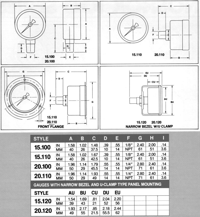
49 Noshok Gauges Page 48
50 Page 49

51 Parker Ball Valve Page 50
52
53 23 Drawing 842E- P/N Gauge Dimensions Page 23-52
54
55 242 Drawing 842E-2 P/N Gauge Details Page 24-54
56
57 Drawing 6242A-SJ8-400 Junction Panel Page
58
59
60 B5-63 Rev.C 2/00 SV2 Spool Valves 3-WAY AIR PILOTED PNEUMATIC VALVE 4-WAY AIR PILOTED PNEUMATIC VALVE MANIFOLD MOUNTED Figure : 4-Way Valve, Air Piloted, Manifold Mounted, Side Ported (Bottom Ported Available) A)SPECIFICATIONS:.Material: Anodized aluminum alloy 360 (SG00B-ASTM) SS spool 2. Maximum operating pressure: 200 psi (4. kg/cm5) 3. Weight: 3 ounces (369 g.) 4. Flow: 40 SCFM at 00 psi B)DESCRIPTION: The SV2 spool valves are available in 3-way or 4-way configuration, air piloted, spring return, spring centered or without springs. C)MAINTENANCE: The SV2 valve should be disassembled periodically for inspection and cleaning. Mark the valve sections as they must be reassembled in the same order. Wash all metal parts with solvent. Clean rubber parts with soap and water and examine them for cracks and signs of wear. Replace worn or defective parts as needed. Do not disassemble the items in DETAIL, as Loctite has been used to hold them to the desired dimension. Service kit SV2-350 contains seals and screws to repair this valve. During re-assembly, lubricate all friction surfaces and seals with Dow Corning III. Northway Products-Mathers Mukilteo, Washington Page th Ave W Mukilteo, WA Telephone (425) Telefax (425)
61 Figure 2: SV2 Breakdown ITEM PART NO. DESCRIPTION ITEM PART NO. DESCRIPTION SV2-003 End Operator 4* CI-03 Screw M5x.8x55(4way) 2 SV2-060 Piston 5 SV End Plate 3* CI-020 O-Ring 6 SV Valve Segment 4 CI-00 Lockwasher 7 SV Valve Segment 5* CI-0 Screw M4x.7x2 8* SV2-702 Seal (Qty depends on valve size) 6* CI-02 Screw M4x.7x50 9 SV2-250 Spool 4-way closed ctr. 7 SV Valve Spacer 20 SV2-0 Spool 4-way supply ctr. 8 SV Bolt 2 SV2-00 Spool 4-way exhaust ctr. 9 SV Washer 22 SV2-240 Spool 4-way, 2 position 0 SV Washer 23 SV2-20 Spool 3-way SV2-602 Spring (Blue) 20 psi * SV2-350 Service Kit SV2-402 Spring (Yellow) 35 psi SV2-305 Spring (Brown) 55 psi MANIFOLDS SV2-302 Spring (Red) 85 psi 3-way SV Side Ported 2 SV2-80 Spring Seat SV Back Ported 3 SV2-070 Push Rod 4-way SV2-902 Side Ported 4* CI-04 Screw M5x.8x35 (3-way) SV2-202 Back Ported Page 26-59
62 Figure 3: SV2 Part Number Breakdown Northway products-mathers Controls Mukilteo, Washington Page th Ave W Mukilteo, WA Telephone (425) Telefax (425)
63 B5-72 Rev.C 2/0 RV8 Relay Valve A) PART NO RV8-600 Relay Valve B) Port Identification. Supply 2. Delivery (Out) 3. Control (In) E. Exhaust C) SPECIFICATIONS: Material:Brass, stainless steel & Buna-N 0484 Operating Pressure: Port 25 psi. Port psi. Limits: Maximum On at 50 psi. Minimum Off at 30 psi. Weight: 4 lbs. Overall Dimensions: 6-/2 x -3/4 x 2 in. D) OPERATION: The RV8 will trip On as the gear oil pressure rises above 40 psi and will trip Off as gear oil pressure falls below 20 psi. E) MAINTENANCE: Periodically disassemble the relay valve for cleaning, inspection and lubrication. Clean all metal parts with solvent, and wash all rubber parts with soap and water. Rinse thoroughly and blow dry with low pressure air. Replace those parts which are worn or damaged. During reassembly, lubricate moving parts and seals with Dow Corning III. Service Kit RV8-60 contains all parts needed to repair this valve. Northway Products-Mathers Controls Mukilteo, Washington Page th Ave W Mukilteo, WA Telephone (425) Telefax (425)
64 ITEM QTY PART NO. DESCRIPTION ITEM QTY PART NO. DESCRIPTION * 7* RV5-00 RV5-020 RV5-030 RV RV8-004 CI-00 CI-04 *Included in Service Kit Cylinder End Cap Retaining Plate Piston Operator Spring O-Ring O-Ring 8* 9* O-Ring MJVO-3C N H FC-6446 MA89-00 AN960-C26L RV8-60 O-Ring Valve Snap-ring Bleeder Fitting Label Flatwasher-SS Service Kit Page 27-63
65 Drawing 799D SP Selector Page 28-64
66
Vickers. Overhaul Manual. Vane Pumps. Small and Large Series Combination Pumps VC(K)(S)-**-(*)*D*-6(1) VC(K)(S)-**-(*)-*-*D*-5(1)
(S)-**-(*)*D*-6(1) VC(K)(S)-**-(*)-*-*D*-5(1)") Overhaul Manual Vickers Vane Pumps Small and Large Series Combination Pumps VC(K)(S)-**-(*)*D*-6(1) VC(K)(S)-**-(*)-*-*D*-5(1) Revised 12/1/86 I-3150-S Table of Contents Section I. Introduction................................................................................
Overhaul Manual Vickers Vane Pumps Small and Large Series Combination Pumps VC(K)(S)-**-(*)*D*-6(1) VC(K)(S)-**-(*)-*-*D*-5(1) Revised 12/1/86 I-3150-S Table of Contents Section I. Introduction................................................................................
SD Bendix E-10PR Retarder Control Brake Valve DESCRIPTION. OPERATION - Refer to Figure 2
 SD-03-832 Bendix E-10PR Retarder Control Brake Valve MOUNTING PLATE SUPPLY 4 PORTS ELECTRICAL AUXILIARY DESCRIPTION TREADLE RETARDER CONTROL SECTION EXHAUST DELIVERY 4 PORTS FIGURE 1 - E-10PR RETARDER
Control Valves & Valve Accessories
 Control Valves & Valve Accessories PNEUMADYNE, INC. Catalog 400 Phone 76-559-077 Fax 76-559-0547 Stainless Steel 0- Fully Ported valve with M5 threads available- contact factory Viton is a registered trademark
AUTOMATIC TRANSMISSIONS Mitsubishi F3A20 Series TRANSMISSION APPLICATION TABLE
 Article Text ARTICLE BEGINNING AUTOMATIC TRANSMISSIONS Mitsubishi F3A20 Series APPLICATION TRANSMISSION APPLICATION TABLE Vehicle Application Transmission Model Colt 3-Speed (1990-94)... F3A21 Colt Vista
PNEUMATIC MARINE PRODUCTS FOR PROPULSION CONTROL
 PNEUMATIC MARINE PRODUCTS FOR PROPULSION CONTROL 2 Pneumatic Marine Products for Propulsion Control AVENTICS Corporation Marine Control Systems such as LOGICMASTER and GEARMASTER Propulsion Control Systems
Valtek Spring Cylinder Linear Actuators
 Valtek Linear Actuators GENERAL INFORMATION The following instructions are designed to assist in installing, troubleshooting and servicing Valtek spring cylinder actuators. Product users and maintenance
REPAIR PROCEDURES MANUAL
 REPAIR PROCEDURES MANUAL PVX Series Vane Pumps A Design Series Step-by-Step Guide to Troubleshooting and Repairing PVX Series Vane Pumps Introduction Thank you for choosing Continental Hydraulics PVX Vane
ORIGINAL INSTRUCTIONS G715A. Pneumatic-hydraulic Riveter E. Warner Ave Santa Ana, CA
 ORIGINAL INSTRUCTIONS G715A Pneumatic-hydraulic Riveter 1224 E. Warner Ave Santa Ana, CA 92705 www.cherryaerospace.com DESCRIPTION The Cherry G715A Pneumatic-Hydraulic Riveter is designed specifically
I & M MK96 & MK96C. Ideal Installation. Start-Up. Maintenance PROTECT VALVES WITH LINE STRAINERS
 **VIP** If you purchased your MK96 or MK96C Valve, or any stem repair component for this valve, after 9/7/08 - please see **VIP** assembly instruction change on page, middle-right, section. I & M MK96
HD-2 CONTROLAIR VALVE
 HD-2 CONTROLAIR VALVE Service Information Description of Models The HD-2 Type Controlair Valves are handle operated 4-way, exhausted center, pressure control valves. The typical unit contains two directional
RELEASING PRESSURE IN THE HYDRAULIC SYSTEM,
 Testing And Adjusting Introduction NOTE: For Specifications with illustrations, make reference to SPECIFICATIONS for 225 EXCAVATOR HYDRAULIC SYSTEM, Form No. SENR7734. If the Specifications are not the
Instruction Manual. Maple 7/15 Pump. Model
 Maple 7/15 Pump Model 10 40 41 Page 2 of 16 Specification Pump Ratio 15:1 Max. Air Pressure Inlet Max. Fluid Pressure Nominal Flow Volume / Cycle 7 Bar 105 Bar 0.166 Litres 0.044 US Gall Fluid Output @
OPERATING INSTRUCTIONS & SERVICE MANUAL BLUE MAX II HYDROSTATIC TEST PUMP
 PAGE 1 OF 10 OPERATING INSTRUCTIONS & SERVICE MANUAL BLUE MAX II HYDROSTATIC TEST PUMP EFFICIENT, EASY OPERATION Air operated pump Wide range of pressures and volumes Easy to operate controls Output pressure
MCV106A. Hydraulic Displacment Control-PV DESCRIPTION FEATURES ORDERING INFORMATION. BLN Issued: March 1991
 DESCRIPTION MCV106A Hydraulic Displacment Control-PV Issued: March 1991 The MCV106A Hydraulic Displacement Control (HDC) is a costeffective hydraulic pump stroke control which uses mechanical feedback
PRODUCT SERVICE MANUAL. BK6DHZ(C)-250, 275, 312 and 400 PUMPS
-250, 275, 312 and 400 PUMPS") PRODUCT SERVICE MANUAL BK6DHZ(C)-250, 275, 312 and 400 PUMPS WARNING This manual, and the GENERAL INSTRUCTION MANUAL, SRM00046, should be read thoroughly prior to pump installation, operation or maintenance.
PRODUCT SERVICE MANUAL BK6DHZ(C)-250, 275, 312 and 400 PUMPS WARNING This manual, and the GENERAL INSTRUCTION MANUAL, SRM00046, should be read thoroughly prior to pump installation, operation or maintenance.
ORIGINAL INSTRUCTIONS G700
 ORIGINAL INSTRUCTIONS G700 HYDRO-SHIFT CHERRYLOCK RIVETER 1224 East Warner Ave, Santa Ana, Ca 92705 Tel: 1-714-545-5511 Fax: 1-714-850-6093 www.cherryaerospace.com G700 HYDRO-SHIFT INSTRUCTIONS TABLE OF
Implement and Steering/Hydraulic System Testing and Adjusting
 Page 1 of 64 Testing And Adjusting Introduction Reference: This supplement contains the Specifications, Systems Operation, and Testing And Adjusting for the components and systems that are different than
980 B Wheel Loader S/n 89P1 & Up Volume 1 of 2
 Caterpillar Service Manual 980 B Wheel Loader S/n 89P1 & Up Volume 1 of 2 Service Manual THIS IS A MANUAL PRODUCED BY JENSALES INC. WITHOUT THE AUTHORIZATION OF CATERPILLAR OR IT S SUCCESSORS. CATERPILLAR
Installation Manual. Model T675A Engine Brakes. For Mack 6 Cylinder, 2 valve Head ENDT-673, 675, 676 & E6 Series Engines.
 Engine Brakes Installation Manual Model T675A Engine Brakes For Mack 6 Cylinder, 2 valve Head ENDT-673, 675, 676 & E6 Series Engines TecBrake P.O. Box 27822 Houston, Texas 77227 INSTALLATION MANUAL TECBRAKE
Material Specifications
 5.2012.12.b 6200 Series Specifications The Flomore 6200 Series Pump line consists of a series of basic pump options all developed from a modular power unit. All units are pneumatically driven positive
PRODUCT SERVICE MANUAL FOR BK12DHZ PUMPS
 PRODUCT SERVICE MANUAL FOR BK12DHZ PUMPS WARNING This manual, and the GENERAL INSTRUCTION MANUAL SRM00046, should be read thoroughly prior to pump installation, operation or maintenance. Manual No. SRM00095
6200 Series. Specifications. Fluid End Power End Models 6211, 6212, 6221, & 6222 Models 6241 & 6242 Part Material Part Material Part Material
 5.2018.12.i 6200 Series Specifications The Flomore 6200 Series Pump line consists of a series of basic pump options all developed from a modular power unit. All units are pneumatically driven positive
MP18 Stacking Valve System Technical Information Manual
 Electric Drives and Controls Hydraulics Linear Motion and Assembly Technologies Pneumatics Service MP18 Stacking Valve System Technical Information Manual The Drive & Control Company Copyright 1996 Bosch
Transmission Overhaul Procedures-Bench Service
 How to Assemble the Lower Reverse Idler Gear Assembly Special Instructions In 1996 Eaton changed the reverse idler system design. In the nut design, the reverse idler bearing was lubricated through a hole
DENISON HYDRAULICS Premier Series. open circuit pump controls P16 B-mod, P09 A-mod. service information
 DENISON HYDRAULICS Premier Series open circuit pump controls P6 B-mod, P0 A-mod service information Publ. S-AM06-A replaces S-AM06 Internet: http://www.denisonhydraulics.com E-mail: denison@denisonhydraulics.com
Pressure Sensor No Series
 Sales Manual Section 335 PRODUCT SPECIFICATION 84372 SERIES Pressure Sensor No. 84372-Series GENERAL DESCRIPTION The patented* No. 84372-Series Pressure Sensor contains a weatherproof, snap-acting valve
DENISON HYDRAULICS open loop pump controls series P140 A-mod, P260 B-mod service information
 DENISON HYDRAULICS open loop pump controls series P10 A-mod, P260 B-mod service information Publ. S1-AM02-A replaces S1-AM02 01-97 CONTENTS typical characteristics-------------------------------------------------------------------------------
Temperature Sensor Series
 GENERAL DESCRIPTION The patented* No. 85026-Series Temperature Sensor contains a two-position valve operated by temperature variations around the integral sensing bulb. It is used to vent or block a pneumatic
Maintenance Information
 51984144 Edition 6 May 2014 Air Paving Breaker MX60 & MX90 Maintenance Information Save These Instructions Product Safety Information WARNING Failure to observe the following warnings, and to avoid these
Model 8329 Table of Contents
 SERVICE & OPERATING MANUAL Original Instructions Instructions Sheet: 670991 Model 8329 Table of Contents Engineering Data and Temperature Limitations... 1 Performance Curve... 2 Dimensions... 3 Metric
Service and Parts Manual. Minimum Filtration Required:
 R GRESEN Hydraulics Model V0 Sectional Body Directional Control Valve Service and Parts Manual Maximum Operating Pressure: Minimum Filtration Required: 00 PSI ( bar) 0 Micron The information in this Service
Purging Air From Divider Block Lubrication Systems
 FROST ENGINEERING SERVICE Purging Air From Lubrication Systems A D I V I S I O N O F G E C S E Y S A L E S & S E R V I C E DESCRIPTION Divider block lubrication systems operate correctly only when all
MULTIPOSITION AIR CYLINDER
 MULTIPOSITION AIR CYLINDER CAST ALUMINUM FOUR-POSITION - ALL AIR SERVICE INFORMATION MOUNTING! Devices should be mounted and positioned in such a manner that they cannot be accidentally operated. INSTALLATION
46RE, 46RH, 47RE, 47RH ZIP KIT
 46RE, 46RH, 47RE, 47RH ZIP KIT PART NUMBER 46-47RHE-ZIP QUICK GUIDE Parts are labeled here in order of installation. See other side of sheet for details on Zip Kit contents. installation Diagram 7 1 Separator
THD-2-FM CONTROLAIR VALVE
 THD-2-FM CONTROLAIR VALVE PART NO. S R431000720 ( Part No. P -027121-00101) R431000721 ( Part No. P -027121-00109) SERVICE INFORMATION DESCRIPTION The THD-2-FM CONTROLAIR Valve, designed for marine service,
AF0465-XX SERVICE KITS GENERAL DESCRIPTION MODEL DESCRIPTION CHART OPERATING AND SAFETY PRECAUTIONS THIS MANUAL COVERS THE FOLLOWING MODELS
 OPERATOR S MANUAL INCLUDING: SERVICE KITS, TROUBLESHOOTING, PARTS LIST, DISASSEMBLY & REASSEMBLY. 4-1/4 AIR MOTORS AF044X-XX (4 STROKE) and AF046X-XX (6 STROKE) Also covers 637489 service kits AF044X-XX
4 - Way Control 4 - Way Control 4 - Way Control with lock
 INSTALLATION / OPERATION / MAINTENANCE 1. DESCRIPTION MODEL 0-02 (Full Internal Port) Powertrol Valve This manual contains information for installation, operation and maintenance of the Cla-Val Co. 0-02
HYDRAULIC PUMP. INSTALLATION, OPERATION, & MAINTENANCE MANUAL MAINTENANCE MANUAL #: MM-HP Rev. A Page 1 of 12
 INSTALLATION, OPERATION, & #: MM-HP001 4-20-09 Rev. A Page 1 of 12 HYDRAULIC PUMP PART NUMBER HP46982ALSL & HP46982SL HYDRAULIC PUMP MM-HP001 Rev. A Page 2 of 12 Table of Contents 1.0 General Page 3 2.0
OPERATION AND PARTS MANUAL
 OPERATION AND PARTS MANUAL MODEL NUMBER : PART NUMBER : TAP- IN KIT 5100-5151 BAYNE MACHINE WORKS, INC. PHONE: (864) 288-3877 910 FORK SHOALS ROAD TOLL FREE: (800) 535-2671 GREENVILLE S.C., 29605 FAX:
ANDERSON GREENWOOD SERIES 500 PILOT OPERATED SAFETY RELIEF VALVES INSTALLATION AND MAINTENANCE INSTRUCTIONS
 Before installation these instructions must be fully read and understood TABLE OF CONTENTS 1. General valve description and start-up... 1 2. Main valve maintenance... 1 3. Pilot maintenance... 5 4. Pilot
Installation Manual. Model T680A/B Engine Brakes. For Mack 6 Cylinder, 4 Valve Head E6 and E7 Series Engines. Engine Brakes
 Engine Brakes Installation Manual Model T680A/B Engine Brakes For Mack 6 Cylinder, 4 Valve Head E6 and E7 Series Engines TecBrake P.O. Box 27822 Houston, Texas 77227 INSTALLATION MANUAL TECBRAKE T680A
Troubleshooting the Transmission Hydraulic System
 Testing and Adjusting IT28F INTEGRATED TOOLCARRIER POWER TRAIN Testing And Adjusting Introduction Reference: For Specifications with illustrations, refer to SENR5974, IT28F Integrated Toolcarrier Power
Ideal Installation. I & M Mark 67 (1/2 6 ) Control Line. Installation & Maintenance Instructions for Mark 67 Pressure Regulators
 Control Line. Installation & Maintenance Instructions for Mark 67 Pressure Regulators") I & M Mark (/ ) 0 Wasson Road Cincinnati, OH 0 USA Phone --00 Fax -8-00 info@richardsind.com www.jordanvalve.com Installation & Maintenance Instructions for Mark Pressure Regulators Warning: Jordan Valve
I & M Mark (/ ) 0 Wasson Road Cincinnati, OH 0 USA Phone --00 Fax -8-00 info@richardsind.com www.jordanvalve.com Installation & Maintenance Instructions for Mark Pressure Regulators Warning: Jordan Valve
B SERIES. Bulletin B-2017
 Bulletin B-207 B SERIES Versa Product Company, Inc., 22 Spring Valley Rd., Paramus, NJ 0762 USA Phone: (20) 4-2400 Fax: (20) 4-29 Versa BV, Prins Willem Alexanderlaan 427, 72 GB Apeldoorn, The Netherlands
I & M Mark 78 Series. Ideal Installation. Start-Up. Installation & Maintenance Instructions for Mark 78 Control Valves (1-1/2-2 )
") I & M Mark 8 Series 0 Wasson Road Cincinnati, OH 4509 USA Phone 5-5-5600 Fax 5-8-005 info@richardsind.com www.jordanvalve.com Installation & Maintenance Instructions for Mark 8 Control Valves (-/ - ) Warning:
I & M Mark 8 Series 0 Wasson Road Cincinnati, OH 4509 USA Phone 5-5-5600 Fax 5-8-005 info@richardsind.com www.jordanvalve.com Installation & Maintenance Instructions for Mark 8 Control Valves (-/ - ) Warning:
Baumann Mikroseal Control Valve
 Instruction Manual 81000 Valve Baumann 81000 Mikroseal Control Valve Contents Introduction... 1 Scope of Manual... 1 Safety Precautions... 2 Maintenance... 3 Installation... 3 Air Piping... 4 Flow Direction...
Valtek Auxiliary Handwheels and Limit Stops
 Valtek Auxiliary s and Limit Stops Table of Contents Page 1 General information 2 Installation 2 Side-mounted handwheels, size 25 and 50 (linear actuators) 3 Side-mounted handwheels, size 100 and 200 (linear
Removal and Installation of Fuel Injection Pumps
 Page 16 of 126 worn considerably. Fig. C shows how the flat end of a new plunger makes poor contact with a worn lifter, resulting in rapid wear to both parts. An injection pump can have a good fuel flow
DENISON HYDRAULICS Premier Series. open loop pump controls series P080. service information
 DENISON HYDRAULICS Premier Series open loop pump controls series P080 service information Publ. S-AM0 Internet: http://www.denisonhydraulics.com E-mail: denison@ denisonhydraulics.com CONTENTS typical
I & M 8000 Series. Ideal Installation Schematic. Preferred Installation. Trouble Shooting
 I & M 8000 Series 3170 Wasson Road Cincinnati, OH 45209 USA Phone 513-533-5600 Fax 513-871-0105 lowflow@richardsind.com www.lowflowvalve.com Installation & Maintenance Instructions for 8000 Series Low
Electronic Proportional (EP) Control for Heavy Duty Series 2 Piston Pumps Model 33
 Control for Heavy Duty Series 2 Piston Pumps Model 33") Electronic Proportional (EP) Control for Heavy Duty Series 2 Piston Pumps Model 33 Model 39 Model 46 Model 54 Model 64 EP Control for Heavy Duty Series 2 Piston Pumps Table of Contents Introduction........................................................................
Electronic Proportional (EP) Control for Heavy Duty Series 2 Piston Pumps Model 33 Model 39 Model 46 Model 54 Model 64 EP Control for Heavy Duty Series 2 Piston Pumps Table of Contents Introduction........................................................................
CUSTOM COMBINATION AIR VALVE
 INSTALLATION / OPERATION / MAINTENANCE CUSTOM COMBINATION AIR VALVE INTRODUCTION This manual will provide you with the information to properly install and maintain this valve to ensure a long service life.
#9040 FUEL TANK SWEEPER
 #9040 FUEL TANK SWEEPER INSTRUCTION MANUAL FILTERS AND REMOVES FINE BIO-CONTAMINANTS, ALGAE, ETC. SWEEPING PROCESS REMOVES LARGE CONTAMINANTS FROM OIL TANKS SUCH AS RUST, WATER, CRUDE AND DIRT CIRCULATES
OPERATION MANUAL. ALUMINUM Models DUCTILE Models 316 S.S. Models AIR-OPERATED DOUBLE DIAPHRAGM PUMPS
 OPERATION MANUAL 3 METALLIC PUMP (CLAMPED) PWR-FLO TM AIR DISTRIBUTION SYSTEM NPF80 AIR-OPERATED DOUBLE DIAPHRAGM PUMPS ALUMINUM Models DUCTILE Models 316 S.S. Models A JDA Global Company CAUTIONS - READ
Super T QR20 INSTRUCTIONS GENERAL RULES
 INSTRUCTIONS GENERAL RULES 1. Where specified, assemble and disassemble the shock absorption system using the MARZOCCHI special tools only. 2. On reassembling the suspension system, always use new seals.
M-3025CB-AV Fuel Pump
 SAVE THESE INSTRUCTIONS M-3025CB-AV Fuel Pump Owner s Manual TABLE OF CONTENTS General Information... 2 Safety Instructions... 2 Installation... 3 Operation... 4 Maintenance... 4 Repair... 5 Troubleshooting...
INSTRUCTIONS. Disassembly. Shifter Cam Assembly. Shifter Forks
 INSTRUCTIONS Disassembly To protect against accidental start-up of vehicle, always disconnect the negative battery cable before working on the motorcycle. Failure to disconnect the battery cable could
PARTS LIST FOR AIR COMPRESSORS AC-SH20-2 AC-SV20-2 ENGINE OIL GRADE: HONDA: SAE 10W-30. Below 40 F=SAE 10W-30 ENGINE OIL CAPACITY:
 PARTS LIST FOR AIR COMPRESSORS AC-SH20-2 AC-SV20-2 ENGINE OIL GRADE: HONDA: SAE 10W-30 VANGUARD: Above 40 F=SAE30 Below 40 F=SAE 10W-30 ENGINE OIL CAPACITY: HONDA: 37 oz. VANGUARD: 40 oz. MAXIMUM PRESSURE
Val-Matic Air / Oil Hydraulic Panel Pump Control System. Operation, Maintenance and Installation Manual
 Manual No. 5AOP-OM1-2 Val-Matic Air / Oil Hydraulic Panel Pump Control System Operation, Maintenance and Installation Manual INTRODUCTION... 1 RECEIVING AND STORAGE... 1 DESCRIPTION OF OPERATION... 1 INSTALLATION...
"HS-2A" DISC BRAKE UNIT CALIPER
 "HS-2A" DISC BRAKE UNIT CALIPER Part No. 0695887 February, 2004 This document is comprised of pages i through viii and pages 1 through 27. Copyright 2004 Wabtec Corporation. P.O. BOX 11 SPARTANBURG, SC
WDV-2 2-way normally closed poppet with air pilot. When valve closes a spring biased internal piston draws back a small volume on outlet side (approx.
 PV-1 MPS-2P SPECIALTY COMPONENTS Miniature pulse valve, a normally open 3-way valve that closes shortly after being pressurized and remains closed until supply pressure is exhausted and repressurized.
OPERATION MANUAL AIR-OPERATED DOUBLE DIAPHRAGM PUMPS 2 POLYPROPYLENE PUMP PWR-FLO TM AIR DISTRIBUTION SYSTEM NPF 50 BOLTED. A JDA Global Company
 OPERATION MANUAL 2 POLYPROPYLENE PUMP PWR-FLO TM AIR DISTRIBUTION SYSTEM NPF 50 BOLTED AIR-OPERATED DOUBLE DIAPHRAGM PUMPS A JDA Global Company CAUTIONS - READ FIRST CAUTION: Do not apply compressed air
Model Table of Contents. SERVICE & OPERATING MANUAL Original Instructions. Instructions Sheet:
 SERVICE & OPERATING MANUAL Original Instructions Instructions Sheet: 670989 Model 8324 Table of Contents Engineering Data and Temperature Limitations... 1 Performance Curve... 2 Dimensions... 3 Metric
Service Manual. #19 Gearmatic Winch
 Allis Chalmers Service Manual #19 Gearmatic Winch Service Manual THIS IS A MANUAL PRODUCED BY JENSALES INC. WITHOUT THE AUTHORIZATION OF ALLIS CHALMERS OR IT S SUCCESSORS. ALLIS CHALMERS AND IT S SUCCESSORS
SD Bendix MV-1 Modutrol DESCRIPTION
 SD-03-3411 Bendix MV-1 Modutrol VALVE A 5-3/8 VALVE B VALVE C VALVE E VALVE D FIGURE 1 - MV-1 MODUTROL DESCRIPTION The Bendix MV-1 modutrol assembly is an integrated air control module designed for dash
INSTRUCTION AND MAINTENANCE MANUAL FR95 PRESSURE REGULATOR
 Enidine / Conoflow 105 Commerce Way Westminster, SC 29693 Tel: (864) 647-9521 Fax: (864) 647-7993 WARNING Conoflow s products are designed and manufactured using materials and workmanship required to meet
Performance Data. Temperature Range. -20 o to 160 o F 26 Hg to 125 psi. C v Flow Rate (scfm) Fill Time Exhaust. Port.
 Fill Time Exhaust. Port.") Control Valves & Valve Accessories PNEUMADYNE, INC. Catalog 00 Phone 76-559-077 Fax 76-559-0547 Features Single stem design Compact size Four input options Numerous porting configurations Fully ported
Control Valves & Valve Accessories PNEUMADYNE, INC. Catalog 00 Phone 76-559-077 Fax 76-559-0547 Features Single stem design Compact size Four input options Numerous porting configurations Fully ported
1/8 NPT (F) 1/8 NPT (F)
 1/8 NPT (F)") Control Valves & Valve Accessories PNEUMADYNE, INC. Catalog 400 Phone 76-559-077 Fax 76-559-0547 Features l Compact size (.5 OAL) l 4 Porting configurations l High flow l Single stem design l Plumbing
Control Valves & Valve Accessories PNEUMADYNE, INC. Catalog 400 Phone 76-559-077 Fax 76-559-0547 Features l Compact size (.5 OAL) l 4 Porting configurations l High flow l Single stem design l Plumbing
OPERATION MANUAL. ALUMINUM Models. 316 S.S. Models NTG25 NOMAD TRANS-FLO AIR-OPERATED DOUBLE DIAPHRAGM PUMPS. A JDA Global Company. 1/14 rev.
 OPERATION MANUAL NTG25 NOMAD TRANS-FLO AIR-OPERATED DOUBLE DIAPHRAGM PUMPS ALUMINUM Models 316 S.S. Models A JDA Global Company 1/14 rev. 3 CAUTION SAFETY POINTS TEMPERATURE LIMITS: Neoprene -17.8 C to
OPERATION MANUAL. ALUMINUM Models DUCTILE Models 316 S.S. Models AIR-OPERATED DOUBLE DIAPHRAGM PUMPS
 OPERATION MANUAL 2 METALLIC PUMP (CLAMPED) PWR-FLO TM AIR DISTRIBUTION SYSTEM NPF50 AIR-OPERATED DOUBLE DIAPHRAGM PUMPS ALUMINUM Models DUCTILE Models 316 S.S. Models A JDA Global Company CAUTIONS - READ
20,000 LB INDUSTRIAL WINCH
 OPERATING, SERVICE AND MAINTENANCE MANUAL 20,000 LB INDUSTRIAL WINCH CAUTION: READ AND UNDERSTAND THIS MANUAL BEFORE INSTALLATION AND OPERATION OF WINCH. SEE WARNINGS! TABLE OF CONTENTS WARRANTY INFORMATION...
SERIES 270A HIGH SIDE FLOAT VALVES BULLETIN 270A-SB11-02 SERVICE BULLETIN
 VALVES VESSELS SYSTEMS CONTROLS SERIES 270A HIGH SIDE FLOAT VALVES BULLETIN 270A-SB11-02 SERVICE BULLETIN System drawings shown in this bulletin are for illustration purposes only. Refrigeration systems
OPERATION MANUAL. ALUMINUM Models 316 S.S. Models AIR-OPERATED DOUBLE DIAPHRAGM PUMPS .5 METALLIC PUMP PWR-FLO TM AIR DISTRIBUTION SYSTEM NPF 15
 OPERATION MANUAL.5 METALLIC PUMP PWR-FLO TM AIR DISTRIBUTION SYSTEM NPF 15 AIR-OPERATED DOUBLE DIAPHRAGM PUMPS ALUMINUM Models 316 S.S. Models A JDA Global Company 2 CAUTIONS - READ FIRST CAUTION: Do not
Maintenance Instructions
 General Note These instructions contain information common to more than one model of Bevel Gear Drive. To simplify reading, similar models have been grouped as follows: GROUP 1 Models 11, 0, 1,, (illustrated),,
HYDROSTATIC TEST SYSTEM MANUAL
 PDQC HYDROSTATIC TEST SYSTEM MANUAL Technical Specification Operating Instructions Part List Revised 12-2016 Manual # PDQC- 6,000 And PDQC-10,000 1 PDQC PERFORMANCE DATA Model Number Maximum Pressure Volume
Adjustable Differential Relay A1
 Sales Manual Section 332 PRODUCT SPECIFICATION MODEL 84871-A1 GENERAL DESCRIPTION The 84871-A1 Adjustable Differential Diverting Relay is a two-position, snap-acting, three-way relay. Its normal function
235/245400, , 28N
 Models 235/245400, 287000, 28N thru W, 310/312/313700 These carburetors have a fixed high speed main jet with adjustable idle, Fig 183. The different carburetors are identified as LMT 1 and up. The letters
1/2" AIR DRIVEN DIAPHRAGM PUMP
 1/2" DRIVEN DIAPHRAGM PUMP OPERATION AND SERVICE GUIDE O-1225D NOV. 2008 Page 1 of 6 Refer to Bulletin P-605, Parts List P-9151 DRIVEN, DOUBLE DIAPHRAGM PUMP MANUAL Congratulations on purchasing one of
I & M Mark 78 Series. Ideal Installation. Start-Up. Installation & Maintenance Instructions for Mark 78 Control Valves (1/2-1 )
") I & M Mark 8 Series 30 Wasson Road Cincinnati, OH 4509 USA Phone 53-533-5600 Fax 53-8-005 info@richardsind.com www.jordanvalve.com Installation & Maintenance Instructions for Mark 8 Control Valves (/ -
I & M Mark 8 Series 30 Wasson Road Cincinnati, OH 4509 USA Phone 53-533-5600 Fax 53-8-005 info@richardsind.com www.jordanvalve.com Installation & Maintenance Instructions for Mark 8 Control Valves (/ -
PMV P36C AND P41C POSITIONERS ACTUATORS
 PMV P36C AND P41C POSITIONERS USED WITH DeZURIK PNEUMATIC ACTUATORS Instruction D10327 August 2012 Instructions These instructions provide information about Models P36C and P41C PMV Positioners. They are
MANUAL TRANS OVERHAUL - BORG-WARNER - T56 6-SPEED MANUAL TRANSMISSIONS Borg-Warner T56 (MM6) 6-Speed
 6-Speed") IDENTIFICATION MANUAL TRANS OVERHAUL - BORG-WARNER - T56 6-SPEED 1998 MANUAL TRANSMISSIONS Borg-Warner T56 (MM6) 6-Speed Transmission has 2 identification labels, located on lower left side of case. One
IDENTIFICATION MANUAL TRANS OVERHAUL - BORG-WARNER - T56 6-SPEED 1998 MANUAL TRANSMISSIONS Borg-Warner T56 (MM6) 6-Speed Transmission has 2 identification labels, located on lower left side of case. One
DeZURIK SPRING RETURN CYLINDER OPERATOR FOR G-SERIES ACTUATORS USED ON PEF 100% PORT ECCENTRIC VALVES
 SPRING RETURN CYLINDER OPERATOR FOR G-SERIES ACTUATORS USED ON PEF 100% PORT ECCENTRIC VALVES Instruction D10466 December 2012 Instructions These instructions provide information about s. They are for
LOGIC VALVE DISASSEMBLY AND SERVICE REPAIR PROCEDURE
 LOGIC VALVE DISASSEMBLY AND SERVICE REPAIR PROCEDURE Service Information WARNING - INSTALLATION AND MOUNTING The user of these devices must conform to all applicable electrical, mechanical, piping and
OpTK. Product Instruction Manual. Spring Cylinder Rotary Actuators INTRODUCTION SAFETY INFORMATION INSTALLATION. Leading Technologies For Control
 Leading Technologies For Control Product Instruction Manual OpTK Spring Cylinder Rotary Actuators TABLE OF CONTENTS INTRODUCTION Safety Information... pg. 1 Unpacking... pg. 1 INSTALLATION... pg. 1 PREVENTIVE
VALVE AND PLUMBING KIT NEW HOLLAND 7310 LOADER NEW HOLLAND TRACTORS
 ASSEMBLY MANUAL Keep With Operator s Manual VALVE AND PLUMBING KIT NEW HOLLAND 73 LOADER NEW HOLLAND TRACTORS MODEL 2WD FWA LESS CAB WITH CAB TT55 X X X TT75 X X X Valve and plumbing kit can be installed
10A 10F 10B 10E 10A 10D 10B. Mr. T 10C Q R
 Q R 2 0 23 30 12 18 17 16 15 14 37 39 38 3 7 6 5 20 26 21 22 40 13 4 2 25 24 8 1 28 27 11 31 19 10A 10D 10B 10C 10 29 10A 10F 10B 10E 10 9 32 36 33 34 35 178 15 GENERAL 82 80 Ø28.6 ±0.1 Ø30 +0.05 0 348
Electronic Proportional (EP) Control for Medium Duty Piston Pumps
 Control for Medium Duty Piston Pumps") Electronic Proportional (EP) Control for Medium Duty 72400 Piston Pumps EP Control for Medium Duty 72400 Piston Pumps Table of Contents Introduction........................................................................
Electronic Proportional (EP) Control for Medium Duty 72400 Piston Pumps EP Control for Medium Duty 72400 Piston Pumps Table of Contents Introduction........................................................................
Valtek VL-HC Spring Cylinder Linear Actuators
 Valtek VL-HC Spring Cylinder Linear Actuators GENERAL INFORMATION The following instructions are designed to assist in installing, troubleshooting and servicing Valtek VL-HC spring cylinder actuators.
Instruction Manual. Maple 60/3 Pump. Model M2
 Maple 60/3 Pump Model 104020-M2 Page 2 of 16 Issue: 1.0 Specification Pump Ratio 3:1 Max. Air Pressure Inlet Max. Fluid Pressure Nominal Flow Volume / Cycle 7 Bar 21 Bar 1.5 Litres 0.4 US Gall Fluid Output
SECTION 4 - FUEL/LUBRICATION/COOLING
 For Arctic Cat Discount Parts Call 606-678-9623 or 606-561-4983 SECTION 4 - FUEL/LUBRICATION/COOLING 4 TABLE OF CONTENTS Carburetor Specifications... 4-2 Carburetor Schematic... 4-2 Carburetor... 4-3 Cleaning
Maintenance Information
 45528270 Edition 1 June 2007 Barring Motor T480 Series Maintenance Information Save These Instructions WARNING Always wear eye protection when operating or performing maintenance on this Barring Motor.
Valves, Fittings, and Manifolds Catalog. We make things MOVE
 Valves, Fittings, and Manifolds Catalog We make things MOVE We Make Things Move A forward-thinking innovator, Bimba provides industry-leading pneumatic, hydraulic and electric motion solutions that are
ACHL Series Pump. Operation and Maintenance Manual Air Driven, Hand Operated High Pressure Liquid Pump
 ACHL Series Pump Operation and Maintenance Manual Air Driven, Hand Operated High Pressure Liquid Pump Catalog: 02-9245ME February 2013 Model # Serial # Drawing # Order # Mfg. Date Table of Contents page
DeZURIK R1 POWERRAC ACTUATOR ON 1/2-3" PEC ECCENTRIC VALVES
 R1 POWERRAC ACTUATOR ON 1/2-3" PEC ECCENTRIC VALVES Instruction D10381 August 2012 Instructions These instructions provide information about the R1 PowerRac actuator. They are for use by personnel who
Troubleshooting The Transmission Hydraulic System
 416B, 426B, 428B, 436B, & 438B BACKHOE LOADERS TRANSMISSION Testing And Adjusting Troubleshooting The Transmission Hydraulic System Make reference to the following warning and pressure tap locations for
TCI Turbo 400 Full Manual Valve Body. Shift Pattern: Park Reverse Neutral First Second Third. NOTE: You must reuse stock manual control valve.
 TCI 221100 Turbo 400 Full Manual Valve Body Shift Pattern: Park Reverse Neutral First Second Third This Kit Contains: (1) Turbo 400 Full Manual Valve Body (1) Separator Plate & Gaskets (1) Pressure Regulator
Page 1 of HP B&S Vanguard Engine
 1405 Page 1 of 41 14 HP B&S Vanguard Engine 1405 Page 2 of 41 14 HP B&S Vanguard Engine Ref # Part Number Qty S/P/F Description BS-28Q777-0647-E1 1 14 HP B&S Vanguard Engine 1 BS-496412 1 Cylinder Assembly
LEAD FREE * LFF113RFP Flood Protection Shut Down Valve
 Technical Bulletin TB-ACV-LFF11RFP LEAD FREE * LFF11RFP Flood Protection Shut Down Valve Installed upstream of Reduced Zone Backflow Preventer. Normally Open Valve - Closes when continuous discharge from
USER INSTRUCTIONS. Valtek Control Products Spring Cylinder Linear Actuators. Installation Operation Maintenance. Experience In Motion
 USER INSTRUCTIONS Valtek Control Products Linear Actuators FCD VLENIM0002-00-AQ - 10/14 (Replaces VLAIM002) Installation Operation Maintenance Experience In Motion 2 GENERAL INFORMATION The following instructions
Electronic Proportional (EP) Control for Heavy Duty Series 0/1 Piston Pumps Model 33 Model 39 Model 46. Model 54 Model 64 Model 76
 Control for Heavy Duty Series 0/1 Piston Pumps Model 33 Model 39 Model 46. Model 54 Model 64 Model 76") Electronic Proportional (EP) Control for Heavy Duty Series 0/1 Piston Pumps Model 33 Model 39 Model 46 Model 54 Model 64 Model 76 Table of Contents Introduction.......................................................
Electronic Proportional (EP) Control for Heavy Duty Series 0/1 Piston Pumps Model 33 Model 39 Model 46 Model 54 Model 64 Model 76 Table of Contents Introduction.......................................................