Holley EFI V4 Software Overview
|
|
|
- Pierce Holmes
- 5 years ago
- Views:
Transcription
.")
1 Holley EFI V4 Software Overview File Changes The calibration file in V3 and earlier versions was called a Global Folder. The Global Folder was actually a Windows Folder which contained multiple files called Individual Configuration Files (ICF). The V4 software utilizes the same Individual Configuration File methodology with one notable change. The main calibration file in no longer a windows folder, and is a single file called a Global File. The user still can add and delete ICFs, but they are all contained within the Global File. The ICF Library still exists as it used to. This will eliminate the need to zip calibration files when ing them. Updating/Converting Files from Older Versions All V3 and earlier files, Global Folders, ICF s, Log Files, and monitor files are not directly compatible with V4, however they can be up-converted. V3 and earlier Global Folders and ICFs will be up-converted when they are opened in the V4 software. V3 and earlier logfiles can be up-converted, but will be converted with a log file conversion tool, that will open when an earlier version logfile is opened. Data Monitor/Logger Changes Many new Data Monitor and Data Logger Channels were added, as well as new Internal Parameters. See section 9. Range Changes Several parameters have had their allowable ranges opened up. They include but are not limited to: Engine RPM- Max RPM increased from 15,000 to 20,000 Ignition Reference changed from 0 to 360 to -360 to This will allow for certain crank/cam sensor combinations to not require a swap in the engine firing order. Engine Coolant and Air Temperature ranges have been increased to 999. Injector Flow Increased to 2000 lb/hr Custom 5 Bar (Map Sensor) This is being renamed to Custom MAP - When selected, it will rescale axes to 999 kpa. It has an allowable range of kpa. This allows the use of MAP sensors up to 999 kpa (130 PSI of boost). TCC TPS WOT unlock raised from 100% TPS to 105%. This allows for this parameter to be set above 100%, which will allow for the Torque Converter Clutch to be locked at 100% TPS. PWM Output tables maximum pulsewidth raised from 128 msec to 99,999 msec. Transmission Torque Management Timing Retard Max retard increased from 10 to 50 degrees of retard. Cranking Timing Increased from 30 to 50 degrees. Base Fuel Table Fuel Flow Increased to 99,999 lb/hr

2 Preference Changes Parameters that require ignition power cycling to initialize If a change is made or a Global folder sent that requires the ignition power/key to be cycled before starting the engine, this will be noted in two ways: o There will be a message that says Ignition Cycling Required Before Start on the bottom right o When a Global File is sent, a popup message will occur saying to cycle the key. This can be turned off in the Preferences. The checkbox in preferences that allows the user to select whether the ECU is an HP or Dominator, has moved to a new tab called ECU Configuration in the System Parameters. The system still autodetects which ECU is present and updates this accordingly. (See below). Display MAP as PSIA This previously only converted the fuel and spark table Y axes. V4 will convert all axes that were previously kpa to PSI. Automatically Open Logfiles When checked, a logfile will automatically open after it has been saved. Turn Off Crank Sensor Inductive Delay Warning checking this will turn off the Inductive Delay warning that pops up if the setting is over 50 usec. ICF Changes and Updates 1.0 System ICF 1.1 ECU Configuration Tab NEW This selection used to be in the Preferences area. It has now been moved to this section. It operates the same as the previous Preference selection. The user can manually select this, or it will be toggled when the system is synced to the ECU. This doesn t change any functional parameters, but will change what I/O are shown on the Pin Map. 1.2 Engine Parameters Load Sensing VE Combo Mode This is a new selection under Load Sensing. It allows for an engine to be run in an Alpha-N mode below a certain engine RPM and TPS, and allow for the existing VE Based fueling strategy to be used above that point. Selecting this will enable the Alpha-N idle fueling table to be activated in the Fuel ICF. Enable Injector End Angle Table checkbox Enables 16x16 Injector Phasing table (See section 1.6). Disabled state retains previous individual Injector End Angle as single end angle value. Also note that the range has been opened up to +/-720 degrees. If updating an older Global Folder, the single end angle value will be retained. 2


3 Fuel System System Type DI Interface This is a new selection that is to be used with future products. Selecting this choice opens up the DI Target Fuel Pressure, which again is for future prodcuts. 1.3 Ignition Parameters Rev Limiter Updates A new rev limiter type has been added called Spark, High Only. This type has a single high side value. It is recommended to use this for a 2-step rev limiter and as a high side rev limiter. Other rev limiter types have had updates to them and can be adjusted to the users desired needs. Programmable Dwell Table An optional 16x16 coil dwell table is available for Custom Ignition Types. The previous, single dwell value is the standard default. To enable this table, the Enable Dwell Table checkbox should be checked. This will replace the single dwell value with an Edit Table button. The table can also be accesses and edited real-time via the Dwell Time selection in the System Parameters ICF dropdowns. The X and Y axes are user programmable as well, with RPM and MAP or TPS typically being the selected X and Y values. If updating an older Global Folder, the single dwell time value will be retained. 1.4 Sensor Scaling Warning Warning setups are available for items (TPS, etc.) that weren t previously there. Coolant and Air Temperature ranges have been allowed to go to much higher values. Make sure values used are within the calibration range of your sensor. 3
 All three retards have a user programmable X axis (Time or RPM).")
4 1.5 Basic I/O TCC: The WOT Unlock TPS value allowed has been increased from 100.0% to 105.0%. This allows for the torque converter clutch to be locked at WOT by allowing a value higher than 100.0%. Timing Retards: The Timing Retards have been updated per the following: Third Retard Added (Retard #3) All three retards have a user programmable X axis (Time or RPM). Previously these were fixed. Activation can be triggered when an input is active ( Activate with Input, which is how versions V2/3 functioned) or a new method that is activated at the release of an input ( Activate at Input Release), such as a trans brake. This will reset/stop when the input is active again, or the ignition is cycled. Users should review these if updating an older Global Folder to V4 that used this feature. 1.6 Injector Phasing Optional 16x16 injector end angle table that is active when enabled in Engine Parameters setup (Injection Type must be Multiport, and Enable Injector End Angle Table must be checked). Fixed X (RPM) and Y (MAP or TPS) axes are copied from Base Fuel table. Injector Auto-Phasing table parameters can be used to calculate and auto-populate the Injector End Table. This auto-population will center the fuel injection event around the camshaft intake lobe centerline. For a more comprehensive overview of this feature, see the Injector Phasing Instructions manual. NOTE: The injector phasing table IS allowed if using non-sequential fueling types (Bank to Bank, Paired, Untimed Sequential). If any of these selections are used, note that since there is no cylinder #1 compression stoke identification (cam sync signal) or the fact that the injectors are fired in multiples, tuning the end angle will not have the precise results that occur when sequential injection is utilized. 4

5 Individual Cylinder Tables: Individual cylinder fueling and timing trim control now has the option tables for each cylinder trim. The individual cylinder fuel trims utilize a 31x16 table and the individual cylinder timing trims use a 16x16 table. To use this option, select the Use Tables checkbox at the top of the Fuel or Timing Correction tables. NOTE: Both the X and Y axis parameters and values are user programmable on EACH individual table. They must be entered on every table individually. To copy X and Y axis parameters AND values from one table to all others, select the Copy Axes to All Cylinders button which is at the top of all screens. IMPORTANT NOTE!!!!! THE TIMING CORRECTION CONVENTION HAS BEEN REVERSED FROM PREVIOUS SOFTWARE VERSIONS. IN V4 SOFTWARE, A POSITIVE VALUE ADVANCES TIMING, A NEGATIVE VALUE RETARDS TIMING. NOTE THAT WHEN AN OLDER GLOBAL FOLDER IS UPDATED, THE VALUE WILL BE SWAPPED AUTOMATICALLY SO THAT THE PROPER CONVENTION WILL BE MAINTAINED. If updating an older Global Folder, the single trim values will be maintained. The sign convention (+/-) will be swapped, in order to not change the calibration. See Important Note above. NOTE CHANGE IN CONVENTION! 5


6 2.0 Nitrous ICF A number of items were added to the Nitrous ICF. Four additional stages were added as well as five more Inputs and four more GPO s, as well as new functionality. Also note a new feature that indicates which stages are activated, and of these, any that are disabled. If using the menus on the left, an active stage will have a green dot. A stage that is activated, but disabled, will have a grey dot. If using the dropdown menus at the top active stages will have a checkmark next to them, while disabled, staged will have the word disabled next to them. 6
7 2.1 Additional Stages Stages 5-8: Four additional stages have been added. Stages 1-8 all have identical functionality. 2.2 Nitrous Parameters Inputs 4, 5, 6, 7, 8: These are additional to the previous three. They retain the same options as well as two new additions that will be helpful for bracket racers using nitrous. See section for more information. Dry Fuel Delay: The single dry fuel delay in the Nitrous Parameters has been removed. A dry delay has been added to each individual stage. When updating a previous version global folder, the single dry fuel delay will be populated in each individual stage. 2.3 GPOs GPO s 5-8: Four additional GPO s have been added. These are additional to the previous four. 2.4 All Stages The nitrous stages have had some re-layout in the software, as well as some new features added Stage X Setup Previous parameters have been grouped into this area, including an individual Dry Fuel Delay for each stage. Each dry fuel delay can be custom set for each stage. When updating a previous version global folder, the single dry fuel delay will be populated in each individual stage. You can now update each per stage Activation/Deactivation Previous parameters as well as new parameters are in this area. Some previous parameters have been renamed as noted below, with the functionality not changing, just their name. Minimum RPM: Previously named RPM Trigger. Nitrous will not be allowed to be activated below this engine speed. Maximum RPM: Previously named RPM Cutoff. Nitrous will not be allowed to be activated above this engine speed. Stage Activation Delay: Previously named Delay. This is the amount of time a stage activation time will be delayed, once all other activation conditions are met. Stage Duration: This is a new parameter. This is used to turn off a stage during a pass. Typically used for bracket/index racing. After a stage is activated, it will turn off after this time. The checkbox must be checked for this feature to be active. Note that the new Override Stage Duration feature in the Inputs can override this time, and turn the stage back on, while this input is active. 7
8 2.4.4 Inputs The Inputs area has 5 more inputs (4-8) added. There are two new choices in all of them as follows. These are typically used by bracket/index racers. Override Stage Duration This input will turn a stage back on while this input is active (must remained pushed/active ), when the stage has been turned off by the Stage Duration parameter. Cancel (until reset) This input will turn a stage off while this input is active (must remained pushed/active ), when the stage is being commanded on otherwise. Also note that Input 3 has an option no other stages offer called, Timed Disable. This will bring up a variable called Input 3 Reactivation Time. When an input is applied to Input 3, selected stages will turn off and turn back on based on the Reactivation Time. This can be used to turn a stage off on a shift, etc. This was a feature present in V Pedaling Control Pedaling Control is an area that determines what each individual nitrous stage will do if the vehicle is pedaled, meaning the throttle/tps movement deactivates and reactivates the nitrous. This area integrates the previous Pause Enabled feature and adds some other options. Pedaling Strategy: There are three choices as follows: Timing Retard None (Full Timer Reset) If the car is pedaled, the stage timers will reset back to time = 0 (zero). This would be the same as not checking the Pause Enabled in previous software versions. Pause Enabled If the car is pedaled, the stage timers will freeze, and restart at this time once the nitrous is reactivated. This would be the same as having the Pause Enabled checked in previous software. Programmable Restart This is a new option. If the car is pedaled, one of two things will happen: 1) If the Stage Timer is LESS than the Stage Restart Time, the nitrous will restart at the frozen Stage Timer times (same as the Pause Enable feature). 2) If the Stage Timer is GREATER than the Stage Restart Time, the nitrous will restart at the Stage Restart Time value. There is one new parameter in the Timing Retard area as follows: Retard Hold After Deactivation: This parameter dictates how long a stage timing retard will be held, after a stage is deactivated. This was fixed/hard-coded to 0.5 seconds in previous versions. This is a safety to keep the timing retarded until all the nitrous has evacuated from an engine. When updating a previous version global folder, the hardcoded 0.5 seconds will be populated in each individual stage. 8
9 3.0 Advanced Tuning ICF The Advanced Tuning (AT) ICF is a new ICF that allows for a variety of operating functions to be modified based on inputs and outputs. It offers significant options and flexibility for engine tuning, power management, and many other items. There are four different table setups offered, which all allow the same tuning options. They consist of the following: 1D Tables There are eight individual tables, each consisting of a 1x16 table. 2D Tables There are eight individual tables, each consisting of a 16x16 table. 1D Per Gear Table There are eight tables, each consisting of up to eight 1x16 tables. Up to eight gears are available. 2D Per Gear Table There are eight tables, each consisting of up to eight 16x16 tables. Up to eight gears are available. 3.1 Setup Gear Based Setup The setup area is utilized if either the 1D or 2D Gear Tables are used. If neither are used, nothing has to be configured. If Gear Tables are used, select one of three methods. If an electronic transmission is being controlled by the ECU, select TCU Input. If the transmission has a single switched input to trigger shift events, select Individual Inputs. If engine speed drop is select RPM Drop for the shift recognition type. If RPM Drop is used, the AT Gear will be estimated by examining the engine speed. If the engine speed goes above Min RPM for Shift Detect and then drops by more than RPM Drop for Shift Detect the AT Gear variable will be incremented by one until it reaches Number of Gears. If the engine speed drops below the value in Automatic Gear Reset RPM for a time greater than Automatic Gear Reset Time, the AT Gear will automatically be reset back to 1 and held until you go back above the Automatic Gear Reset RPM. If you check the box for Manual Gear Reset then asserting the Manual Reset input will reset the AT Gear back to 1. If Individual Input is used, the AT Gear will be incremented by active edges of the Man. Shift Input until it reaches Number of Gears. If the engine speed drops below the value in Automatic Gear Reset RPM for a time greater than Automatic Gear Reset Time, the AT Gear will automatically be reset back to 1 and held until you go back above the Automatic Gear Reset RPM. If you check the box for Manual Gear Reset then asserting the Manual Reset input will reset the AT Gear back to All Tables (1D, 2D, 1D per Gear, 2D per Gear) To use a table, the Enable Table checkbox box must be selected. Next enter a description for the Name of the table that makes identification of the table easy. This will show up on the Data Monitor and Data Logger as the name entered. This value will be indicative of the table modifier value. There are options for certain Table Types to inhibit closed loop or fuel learning when that Advanced Tuning table is active. Select the checkboxes for Inhibit CL Compensation when Activated or Inhibit Base Fuel Learn when Activated to inhibit these operations. Next, enter the Table Type, which will select the modifier. 9
10 Note the following nomenclature on these: Offset Adds or subtracts a raw value from the modified parameter Multiplier Performs a percentage increase or decrease to the modified parameter. Important Note: If multiple Multiplier tables are used for the same function, they will be multiplied together. For example, one might be using a table for E85 compensation and another for fuel pressure compensation. If the final fuel flow is 100 lb/hr, and one table is adding 25% more fuel and the other taking out 10% the math works out to: 100 lb/hr * 1.25 *.90 = lb/hr. Note that how this value affects the parameter is indicated in the software above the graph. The neutral value that does not perform any modification is specified. The following items can be modified: Fuel Flow Offset Adds or subtracts fuel to the final fuel flow value. Note that the final fuel flow includes AE fuel, nitrous enrichment, and all other fuel modifiers, etc. It also modifies cranking fuel. VE Based Fuel Flow Offset Adds or subtracts VE% to the final VE value. AE Fuel Flow Multiplier Multiplies the final AE Fueling value. Fuel Flow Multiplier Multiplies the final fuel flow (no matter what type of fueling strategy is used, whether it be lb/hr or VE based) by this amount. Note that the final fuel flow includes AE fuel, nitrous enrichment, and all other fuel modifiers, etc. It also modifies cranking fuel. Timing Offset Adds or subtracts timing to the final timing value. Target Air/Fuel Ratio Offset Performs an offset to the target A/F ratio. NOTE: If this modifier is employed, the final fuel flow value is offset by the ratio of the base target air/fuel ratio, and the offset performed. For example, if the base target air/fuel ratio is 12.0:1, and an offset of -1.0 is performed (effectively richening the target to 11.0), the final fuel flow will automatically increase by 8%. Target Air/Fuel Ratio Multiplier Multiplies the Target Air/Fuel ratio by this value. Closed Loop Compensation + and Overrides When this table becomes active, the tuner has the ability to override the base Closed loop Compensation Limits % table with this new value. Target Idle Speed Offset Adds or subtracts to the target idle speed value. IAC Position Offset Adds or subtracts to the current IAC Position. Boost Offset Adds or subtracts to the target boost level. The target boost will be either dome pressure or actual boost depending on how the boost control is set up in the software. Nitrous Stage 1-8 Offset This will offset the nitrous percentage by the value entered for the stage specified. Drive By Wire Offset This will offset the commanded drive by wire throttle body position. 10
11 Note that the following maximum limits will be allowed for the first three Pedal Position cell values: 0% - 25% 7% - 35% 13% - 45% Limits: The throttle can be DECREASED by 100%, however a limit of 5% is allowed to be added. Cylinder #1 - #8 Timing Offset Offsets individual cylinder timing based on this value. Cylinder #1 - #8 Fuel Multiplier Multiplies final individual cylinder fuel values based on this value. If there are trims in both the System Parameter trims as well as the Advanced ICF section, they will be multiplied together. For example, if the trims are 8% and 5% for a single cylinder, it will equate to 1.08 * 1.05 = 1.134, or 13.4%. Injector End Angle Offset Offsets the base Injector End Angle value Cranking Fuel Multiplier Multiplies the base cranking fuel number by this value. Finally, select the X and Y (for 2D tables) axis parameters. The axis break points are fully user-editable. There are many options available that can be used for the X and Y axes including basic engine sensors, multiple operational parameters, Advanced Tuning ICF Tables values, Input / Output ICF sensor input variables, Nitrous, Boost Control, Transmission, Water Meth, Drive By Wire, and other items. 3.2 Activation These functions can be activated based on a wide range of inputs and outputs. The tables can be activated based on the release of an input such as a trans-brake. They can also be activated base on a switched or sensor input. A tuner/user should possess a high level of knowledge to use these functions. If none of the activation conditions are selected, the particular Advanced Tuning table will be active all the time. Note that each activation table must be set up for every table, even if the activation conditions are all the same. Select the AT Launch Input Enabled Checkbox if this functionality is desired. If checked, an input must be pin mapped. When this input is active and released (such as a trans brake), the table will be active. Once the table is deactivated, this input must be active and released to enable/start the table again. The Time Delay to Start, if enabled will delay the activation of this table when the table is active. This time will be added after either/both the AT Launch Input is used, as well as the Activation parameters are met. The Activation parameters, if enabled, provide methods of activation conditions for the table. The Switched Enable provides a dropdown of choices that allow table activation when they are either in an enabled or disabled state. Note that some of the dropdown choices can be items that have variable values, not just items that are on or off. If one of these are selected, they will allow activation whenever they are in an active state. The Advanced Enable allows table activation by a parameter that allows the user to select the values above/below as well as a deactivation value. If both are enabled, the AND/OR value can be chosen to indicate whether one or both conditions have to be active for table activation. The table/graph is where the particular tuning modifier is edited. 1D tables are shown with a table and graph. 2D tables are shown with a table, with a graph button available. The X and Y axis values may be edited as needed as well D Tables 16x16 table. Same as 1D tables, except a Y axis variable is selected. 11
12 3.4 1D Per Gear Tables Same as 1D table, except one table is available for each gear 3.5 2D Per Gear Tables Same as 2D Table, except one table is available for each gear 3.6 Inputs/Outputs There are three Inputs that can be activated and need to be pin mapped. AT Shift This is used for gear based setup if the Shift Recognition is set to Individual Input. This is used to increment a gear change. AT Launch This is used if the AT Launch Input Enabled checkbox is selected. This will activate the specific table once this input is released (such as a trans brake). AT Manual Reset This is used for gear based setup (if the Shift Recognition is set to RPM Drop or Individual Input. Once activated, the Gear will reset to Gear Traction Control ICF 4.1 Setup System Type added allows user to select from TC1/TC2 selection, or new Profiler or Profiler with Smart Drop 4.2 Inputs/Outputs Profiler Input and Smart Drop Input added. 5.0 I/O ICF 5.1 Inputs Nomenclature Change The previous TYPE dropdown names were changed: DIGITAL SPEED to DIGITAL SPEED/FREQ - IPU SPEED to IPU SPEED/FREQ Added new DIGITAL SPEED/FREQ types: o GM Flex Fuel Allows the use of Hz flex fuel sensors. Will read in % Ethanol content. A common part number for a cost effective compatible sensor is Continental PN The pigtail for this sensor is GM PN This sensor should be wired in the following manner: Pin 1 (Vcc) Connect to switched voltage (12V) Pin 2 (Gnd) Connect to a solid ground Pin 3 (Out) Flex fuel sensor input to ECU. Connect to whatever ECU this is mapped to. This input also must be connected to a 5v wire via a 10k (10,000) Ohm pullup resistor. Any 10k Ohm resistor can be used. See the diagram below. Tie one end of the resistor to the flex fuel sensor input and the other to one of the ECU 5v lines. These pins are shown on the diagram below. 12

13 To configure the flex fuel operation, see the examples in the addendum at the end of this document. o o Frequency Will indicate/record frequencies up to 20,000 Hz Custom Frequency Allows for devices with variable frequency outputs to be set up using a calibration table. Added new IPU SPEED/FREQ types o Frequency o Custom Frequency 5.2 Outputs Some very useful additions have been made to the Outputs section Added AND/OR to the Switched and Sensor Input Triggers. This allows for the option of both (AND) or either (OR) of the Switched and Sensor input triggers to be required to activate an output. When updating a previous version global folder, the AND will be automatically populated as was previously the case. There are new options available that can be selected for the Sensor Input Triggers for an output. These include some new engine operational parameters and Advanced Tuning ICF Tables values. Timer option There is now a timer option for an output. Each timer function can be individually enabled. They are the following: Start Activation Delay Once all the Switched and Sensor Input Trigger conditions are met, this delay will be used before the output is performed. This is a one time delay. It will only re-occur once the activation conditions (Switched and Sensor Input Triggers) drop out and re-occur. 13
 drop out and re-occur, OR if the Repeat checkbox is select, and after the")
14 Active Time This is the length of time the output will be active for. If/once this time is met, the output will de-activate. Once this time is met, the timer will only restart once the activation conditions (Switched and Sensor Input Triggers) drop out and re-occur, OR if the Repeat checkbox is select, and after the Inactive Time occurs. If the Repeat is option is selected, the output will starts WITHOUT the Start Activation Delay entering into play.. Repeat Checkbox - This checkbox will enable the Inactive Time function. Inactive Time - This parameter will be only available if the Repeat checkbox is selected. It will be the time that the output will be turned OFF, before it starts again and remains on for the Active Time. Note that a diagram of how the output will operate depending on how it is configured will be show for each combination of selections in the software. The following are some examples of how the timer function can be set up. Note that these can be +12V or Ground Outputs. All examples shown are +12V. +12V Output with Start Delay, Active Time, No Inactive Time 14
15 PWM+ Output with Start Delay, Active Time, No Inactive Time +12V Output with Start Delay, Active Time, and Inactive Time PWM+ Output with Start Delay, Active Time, and Inactive Time +12V Output with Start Delay, No Active Time, No Inactive Time 15
16 PWM+ Output with Start Delay, No Active Time, No Inactive Time +12V Output, no Delay, with Active Time, no Inactive Time PWM+ Output, no Delay, with Active Time, no Inactive Time +12V Output, no Delay, with Active Time, with Inactive Time 16
17 PWM+ Output, no Delay, with Active Time, with Inactive Time +12V Output, no Delay, no Active Time, no Inactive Time PWM+ Output, no Delay, no Active Time, no Inactive Time 6.0 Boost ICF 6.1 Boost ICF Changes Boost vs Gear & Boost vs RPM - Changed Number of Gears from 6 to 8. Boost vs Speed X speed axis now user programmable 7.0 Fuel ICF 7.1 A/F Offset Table The A/F ratio offset table has been modified in the following ways: - The rich/lean convention has been changes such that a positive value LEANS the target A/F ratio - Positive and negative values are both now allowed. 17

18 When updating a previous version global folder, the sign convention will be changed from positive to negative automatically, so that the tune isn t changed. 7.2 Base Fuel Table Conversion The Conversion checkbox on the base fuel table as well as graph will toggle a fuel flow based table to VE or visa-versa. A new functionality is that you can edit the table when it is in its converted mode. This can be very advantageous and allows smoothing and editing in either fuel flow or VE fueling modes. 8.0 Sensor ICF The previous MAP sensor selection of Custom 5 bar is now renamed to Custom MAP. It allows for any MAP sensor up to 999 kpa (130 PSI). Selection of this sensor will autoscale the MAP axes to 999 kpa. Custom coolant temp allows higher temperature range (999F) than was previously (260F) allowed. Make sure that the sensor you are using has accuracy in the ranges you specify. (Standard sensors are also allowed to go to 999F in the Sensor Scaling area as well) Custom MAT temp allows higher temperature range (999F) than was previously (275F) allowed. Make sure that the sensor you are using has accuracy in the ranges you specify. (Standard sensors are also allowed to go to 999F in the Sensor Scaling area as well) 9.0 New Data Monitor and Logger Parameters Estimated VE This parameter was introduced in V3. This parameter estimates the VE taking into account what the closed loop fuel trimming is performing. If you are manually tuning an engine, you can use this value to help in more quickly tuning the base VE table. Timing Retard #3 This indicates the status (on/off) of the new Timing Retard #3. Note that the X axis time value (as well as Timing Retards #1 and #2) be displayed via the use of new internal parameters called System_TimingRetard#1/2/3_Time Base Fuel lb/hr Indicates the base fuel value (lb/hr) from the base fuel map. All modifiers are not included Base Fuel VE Indicates the base fuel value (VE) from the base fuel map. All modifiers are not included. Base Timing Indicates the base timing value from the base timing table. All modifiers are not included. Base Target AFR Indicates the base target air/fuel from the target A/F table. All modifiers are not included. 18
19 Base Ign Dwell Indicates the base ignition dwell, that is either from the user input single dwell value, base dwell table, or hard coded from the Ignition Type selected. This is the nominal value at 13.8 battery volts. More or less voltage will change this value, which is indicated by the Vol Comp Ign Dwell internal parameter. Vol Comp Ign Dwell This is the actual coil dwell, which is based on the Base Ign Dwell, and modified by battery voltage. Inj End Angle Indicates the injector end angle, whether using the single value, or the base table. If the end angle offset in the Advanced ICF is being used, this will be included. ECU Log Trigger Indicates if internal ECU logging is active. Timing vs Air Indicates the Timing vs. Air Temp modifier value. Timing vs Cool Indicates the Timing vs Coolant Temp modifier value. Status 1-8 (Eight Parameters) These are not used at this time. Injector #1-12 PPH (Twelve Parameters, Injectors 1 through 12) Indicates the flow (in theoretical lbs/hr) that each injector is delivering. This takes into account the individual injector cylinder trims. Injector #1-12 PW - (Twelve Parameters, Injectors 1 through 12) Indicates the injector pulse width (msec) of each injector. This takes into account the individual injector cylinder trims. Cyl #1-16 Fuel Cor (Sixteen Parameters, Cylinders 1 through 16) Indicates the individual cylinder fuel correction (%) of each injector. Cyl #1-16 Timing Cor - (Sixteen Parameters, Cylinders 1 through 16) Indicates the individual cylinder timing correction (degrees) of each injector. Boost Master Enbl Indicates the status of the boost master enable input. Boost Man Shift Inp Indicates activation of the boost manual shift input. Boost Fill Sol DC Indicates the boost control fill solenoid duty cycle. Boost Vent Sol DC Indicates the boost control vent solenoid duty cycle. W/M Sol 1 Flow Indicates the theoretical flow from water/meth injection solenoid #1. W/M Sol 2 Flow Indicates the theoretical flow from water/meth injection solenoid #2. W/M Flow Total Combined theoretical flow from water/meth solenoids #1 and #2. W/M Sol 1 DC Indicates the duty cycle of water/meth injection solenoid #1. W/M Sol 2 DC - Indicates the duty cycle of water/meth injection solenoid #2. N20 Stage 5-8 (Four Parameters, Nitrous stages 5 through 8) Indicates the % activation of nitrous stages five through 8. GPO 5-8 (Four Parameters, GPO s 5 through 8) Indicates the output values from GPO s 5 through 8. N20 Input #4-8 (Five Parameters, Inputs 4 through 8) Indicates the input status of inputs 4 through 8. N20 Dry Fuel #1-8 (Eight Parameters, Nitrous Stages 1 through 8) Indicates the dry fuel flow (lbs/hr) of each individual nitrous stage. 19
20 N20 Tmg Mod #1-8 (Eight Parameters, Nitrous Stages 1 through 8) Indicates the timing retard of each individual nitrous stage. N20 Timer #1-8 (Eight Parameters, Nitrous Stages 1 through 8) Indicates the value of each nitrous stage timer. A negative value indicates the stage is not active, but counting down to activation. A positive value indicates the stage is active. Trans Man US Input Indicates a manual upshift input to an electronic transmission. Trans Man DS Input Indicates a manual downshift input to an electronic transmission. Trans Auto/Man In Indicates the status of the transmission Auto/Manual mode input. Diag #11-20 New diagnostic parameters that are not being used at this time. Advanced ICF Parameters: AT Launch Input Indicates the state of the launch input. AT Shift Input Indicates a shift input. AT Manual Reset Indicates a manual gear reset. AT Gear Indicates the indicated gear. AT 1D #1-8 (Eight Parameters) Note that these will be renamed to whatever the Name is in the Setup area. These will be show the value and units of the parameter being modified. AT 2D #2-8 (Eight Parameters) Note that these will be renamed to whatever the Name is in the Setup area. These will be show the value and units of the parameter being modified. AT 1DGear #1-8 (Eight Parameters) Note that these will be renamed to whatever the Name is in the Setup area. These will be show the value and units of the parameter being modified. AT 2DGear #1-8 (Eight Parameters) Note that these will be renamed to whatever the Name is in the Setup area. These will be show the value and units of the parameter being modified. New Internal parameters: AT_1D#1-8_Xaxis AT_2D#1-8_Xaxis AT_1DperGear#1-8_Xaxis AT_2DperGear#1-8_Xaxis AT_Gear System_TimingRetard#1-3_Time Trans_TargetGear Trans_AdvancedTorqueTimingTriggered Trans_AdvancedTorqueTiming Trans_BrakeswitchLockup Trans_ShiftSolenoidA12 Trans_ShiftSolenoidB23 Trans_ShiftSolenoid32 Trans_LineTempStatusLockup Trans_TpsStatusLockup 20

21 10.0 Calibration Updater and Calibration File Comparison V4 software includes a utility to convert previous V2/V3 calibration files (Global Folders) and ICF s to V4 versions as well as a utility compare two V4 calibrations. These will automatically be installed when the V4 software installed. To access them, in Windows 8, go to the Start screen and then the Apps screen and they should be under the Holley V4 area. Windows 7 and 10 should find them under the Start button. The Calibration Updater is called Holley EFI V4 GCF Conversion Tool. The Comparison Tool is called Holley EFI V4 GCF Comparison Tool Global Folder and ICF Converter The HEFI V4 GCF Converter can convert both V2/V3 Global Folders and V2/V3 ICF s to V4 versions in one quick conversion. First open the program, it will look like this: Next, select a Source Directory and then an Output Directory. You can create a new Output Directory during this process if desired. If you click the Convert ICF s checkbox, all ICF s of the ICF s contained within the Global Folders will be converted into V4 ICF s. These will be contained in the Output Directory in folders with the Global Folder name. Note that if you have directories within the Source directory, Global Folders and ICF s within, will be converted as well, with the directory structure maintained in the Output Directory. Once you select the Source Directory and the Output Directory, select the Run button and the conversion will take place. 21

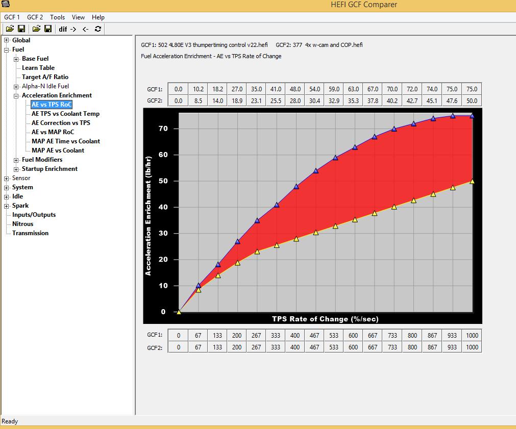
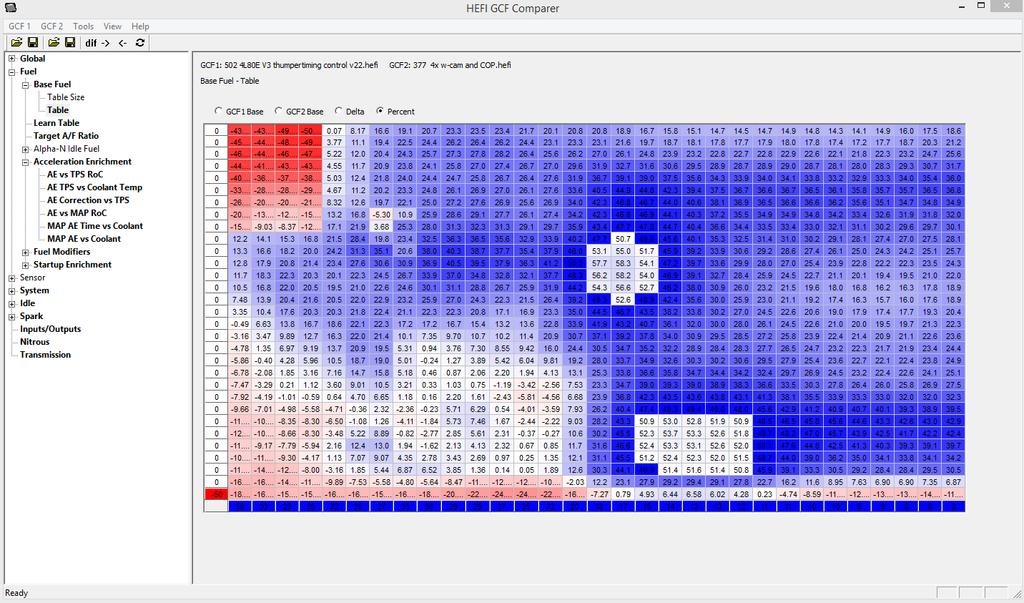
22 10.2 HEFI GCF Comparer V4 software includes a calibration file comparison tool. Once the program is opened it will look like this: Click on the GCF 1 tab and select Open. Select a calibration. Then click on the GCF 2 tab and select open. Select a calibration. Once both are selected, a selection tree will appear on the left. It will show all of the different ICF s. If an ICF is bold, it means were are differences between the two calibration. If not bold, they are the same. Click on the + sign to open up the tree to move deeper into the comparison. If an item appear bold, it means there are differences. Once you reach a table, select it. The table will open and show the values of both tables. Different tables have different methods of showing the comparison. If you want to only show the tables with differences, select Tools and select the Show Differences Only. The program has the ability to copy tables from one calibration to another. You can copy multiple tables/complete ICF s at one time. To copy a single table, open just that table, which will be at the end of the tree. Select Tools and then either Copy from File 1 to File 2 or Copy from File 2 to File 1. To copy multiple screen or an entire ICF, place the cursor on the tree structure at a higher level in the tree. The select the copy functions. All parameters below this level will be copied. The copy is not transferred permenantly until it is saved. To save a file, click the save icons (small disk). There is one for both File 1 (left) and one for File 2 (right) that must be done for either file. You can also select the GCF1/GCF2 dropdowns and perform a Save or a Save-as. 22
23 23
24 24

25 APPENDIX Advanced ICF Examples Flex Fuel Capability The following are steps in setting up a flex fuel capable system. The tables can be customized such that the ethanol content modifies whatever parameters are desired, such as various fuel flows, ignition timing, boost levels, etc. Step 1 Create Digital Speed/Frequency input. It s called Flex Fuel Sensor in this example. Set the Type to GM Flex Fuel. Connect the flex fuel sensor. Section 5.1 reviews sensor selection and wiring. 25
26 Step 2 Add the Advanced Tuning ICF. Open a 1D table and enter a name (called Flex Fuel Mult. in this example). Select Fuel Flow Multiplier for the table type. Select whatever name was given to the flex fuel sensor ( Flex Fuel Sensor in this example). This table configuration will multiply the final fuel flow value, dependent on this table, based upon what the flex fuel sensor is reporting as the ethanol content of the fuel. This table is set up so that 34% more fuel is added to the final fuel flow, when the sensor is reporting 100% ethanol, which is appropriate for most pump gas and ethanol blended fuels. At this point, these additions would be enough to support basic flex fuel functionality. Steps 3-4 add more tuning options to flex fuel capability. 26

27 Step 3 Open another 1D table. Name it Flex A-F Offset. This table can be used to richen the target Air/Fuel Ratio as load increases, which sometimes can make more power when using E85. You could use a 2D table as well and add another parameter to the table, such as MAP. This would allow one to alter the target A/F based on load and ethanol content. 27
28 Step 4 Open another 1D table. This table will alter ignition timing vs ethanol content. The added octane of E85 could allow for a more aggressive timing curve. Other tables can be added, such as a ethanol content vs boost curve, what would add more boost with higher ethanol content. Many Other Possibilities There are limitless things that can be accomplished with these tables. A few examples. - Fuel Pressure Compensation Table - Modification of fuel or timing per gear - Idle speed or IAC modification for marine or other applications - Cylinder based Fuel or Timing trims per gear - Boost control trims based on any parameter - Nitrous modifications based on any parameter - Timing advance or retard under many conditions 199R10884 Date:
Active Speed Management Time based traction control based on engine speed and/or driveshaft speed.
 Contents V5 Feature Overview... 1 Custom Injector Setup... 2 Custom Injector Setup - System ICF... 2 Injector Set #1/#2/#3... 3 Driver Setup... 4 Custom Injector Setup - Fuel ICF... 5 Wiring Holley Injector
QUICK START GUIDE 199R10546
 QUICK START GUIDE 199R10546 1.0 Overview This contains detailed information on how to use Holley EFI software and perform tuning that is included within the software itself. Once you load the software,
Lingenfelter NCC-002 Nitrous Control Center Quick Setup Guide
 Introduction: Lingenfelter NCC-002 Nitrous Control Center Quick Setup Guide The NCC-002 is capable of controlling two stages of progressive nitrous and fuel. If the NCC-002 is configured only for nitrous,
GENERAL MOTORS SERVICE PARTS OPERATION 6200 Grand Pointe Drive, Grand Blanc, MI 48439
 LS IGNITION CONTROLLER 19355418 Ignition Control for Carbureted LS Series Engines (24x Crankshaft Index/1x Camshaft Index, 58x Crankshaft Index/4x Camshaft Index) Parts Included Quantity Ignition Controller
Setup Tabs. Basic Setup: Advanced Setup:
 Setup Tabs Basic Setup: Password This option sets a password that MUST be entered to re-enter the system. Note: ProEFI can NOT get you into the calibration if you lose this password. You will have to reflash
Holley EFI 16 Injector Setup (8 Cylinder Engines) Setup of 8 Injectors in 8:2 Amp Peak and Hold Mode
 Setup of 8 Injectors in 8:2 Amp Peak and Hold Mode") Holley EFI 16 Injector Setup (8 Cylinder Engines) Setup of 8 Injectors in 8:2 Amp Peak and Hold Mode TABLE OF CONTENTS: 16 Injector Setup (4 Options)... 1 General Information... 2 16 Injector Option 1...
Holley EFI 16 Injector Setup (8 Cylinder Engines) Setup of 8 Injectors in 8:2 Amp Peak and Hold Mode TABLE OF CONTENTS: 16 Injector Setup (4 Options)... 1 General Information... 2 16 Injector Option 1...
BigStuff3 - GEN3. 1st Gear Spark Retard with Spark Retard Traction Control System (SR 2 ) Rev
 Rev") BigStuff3 - GEN3 1st Gear Spark Retard with Spark Retard Traction Control System (SR 2 ) 12-09 System Description 1st Gear Spark Retard with Spark Retard Traction Control System (SR 2 ) - SR 2 uses two
BigStuff3 - GEN3 1st Gear Spark Retard with Spark Retard Traction Control System (SR 2 ) 12-09 System Description 1st Gear Spark Retard with Spark Retard Traction Control System (SR 2 ) - SR 2 uses two
MAXIMIZER-II Progressive Nitrous Controller INSTALLATION AND USER MANUAL. MAXIMIZER-II rev A
 MAXIMIZER-II Progressive Nitrous Controller INSTALLATION AND USER MANUAL i Table of Contents Page 1. Installation Overview...1 1.1 MAXIMIZER-II Power Input...1 1.2 SOLENOID DRIVER Ground...1 1.3 Arming
Installation Instructions for: EMS P/N Ford Mustang 5.0L
 Installation Instructions for: EMS P/N 30-1401 1994-95 Ford Mustang 5.0L! WARNING: This installation is not for the tuning novice nor the PC illiterate! Use this system with EXTREME caution! The AEM EMS
MPFI FUEL INJECTION SYSTEM
 MPFI FUEL INJECTION SYSTEM PART NUMBERS 550-903 thru 905, 550-916 thru 918 & 550-926 thru 931 HANDHELD TUNING AND REFERENCE MANUAL 199R11761 1 CONTENTS Tuning... 4 Basic... 4 Basic Fuel... 4 Closed Loop
Series 2 EMS Notes: 02v02 Firmware Updates
 Series 2 EMS Notes: 02v02 Firmware Updates There are many new features and functions in the 02v02 firmware update for the Series 2 EMS. This document is intended to outline these new additions as well
Subaru BRZ Toyota GT86 Scion FR-S
 RaceROM Features for Subaru BRZ Toyota GT86 Scion FR-S v1.8 Index Warning... 3 Introduction... 4 Feature list... 4 Supported Vehicle Models... 4 Availability... 4 Overview... 5 Map Switching**... 5 Speed
WIRING MANUAL & DIAGRAMS 199R10555
 WIRING MANUAL & DIAGRAMS 199R10555 HP EFI and Dominator EFI Systems Contents 1.0 Manual Overview... 2 1 1.1 Important Wiring Do s and Don ts... 3 2.0 ECU Installation, Connectors, and Pinout... 3 2.1 Pinout...
MSD LS Ignition Control PN 6014/60143
 MSD LS Ignition Control PN 6014/60143 ONLINE PRODUCT REGISTRATION: Register your MSD product online. Registering your product will help if there is ever a warranty issue with your product and helps the
Controller Ground (dual black 12awg) should be connected to chassis ground as close as possible to the battery.
 should be connected to chassis ground as close as possible to the battery.") 1. Overview The Maximizer 4 progressive nitrous controller operates one or two separate stages of nitrous based on either time, RPM, MPH, throttle percentage or boost pressure. Whether your engine is naturally
1. Overview The Maximizer 4 progressive nitrous controller operates one or two separate stages of nitrous based on either time, RPM, MPH, throttle percentage or boost pressure. Whether your engine is naturally
Installation Instructions for: EMS P/N Ford Mustang 5.0L
 Installation Instructions for: EMS P/N 30-1400 1986-93 Ford Mustang 5.0L! WARNING: This installation is not for the tuning novice nor the PC illiterate! Use this system with EXTREME caution! The AEM EMS
COBB TUNING. AccessTUNER. USDM Mitsubishi Table Descriptions and Tuning Tips. Copyright 2008 Cobb Tuning Products, LLC. All Rights Reserved. P.
 COBB TUNING AccessTUNER TM USDM Mitsubishi Table Descriptions and P.1 Note: This is a list of tables available on all Mitsubishi AccessTUNER products. Not all tables are available in your software. Boost
GENERAL ANDROID DEVICE RECOMMENDATIONS
 GENERAL ANDROID DEVICE RECOMMENDATIONS The Edelbrock EFI E-Tuner app is compatible with most Android based Smartphones and tablets operating on Android 5.0 and later. However, due to slight variations
Workshop Training Notes
 Workshop Training Notes Fuel Basics Theoretical Pulsewidth X Short Term Trim (Closed loop) X Long Term Trim (Stored) Total fuel calculations + Injector latency = Injector Pulsewidth X MAF Load Calculation
AUTRONIC SM3 ECU Specifications
 AUTRONIC SM3 ECU Specifications Microcomputer Power Supply - Voltage Normal operation Operational limits Intel 16 bit 20MHz 12v to 15v DC 6.2v to 18v DC continuous Power Supply - Current Survival limits
OMEM200 Tuning Manual 3v Series ECU. Tuning Manual OMEM200.
 200 Series ECU Tuning Manual OMEM200 www.omextechnology.com 0 1 Introduction... 3 1.1 What this manual covers... 3 1.2 Notation Used in This Manual... 3 2 Software... 4 3 Sensor Setup... 5 3.1 Throttle
ProECU Mazda MX-5. Live Data Guide 2005-onward Model Year. v1.06
 ProECU Mazda MX-5 Live Data Guide 2005-onward Model Year v1.06 Live Data Live Data Display ProECU Mazda MX-5 can offer real time exceptionally high speed data display and the ability to log this displayed
DFS-1000 Wiring Diagrams and PC Software Installation.
 DFS-1000 Wiring Diagrams and PC Software Installation. For Technical Support Please contact your dealer or email seellc@mchsi.com 1 Important Information - When using a conventional style ignition coil
C.A.T.S. Tuner ECM_NS3 Parameter List (ECM Configuration File Version F) ECM Switch Parameters
 ECM Switch Parameters") C.A.T.S. Tuner ECM_NS3 Parameter List (ECM Configuration File Version F) ECM Switch Parameters VATS Option (X = Enabled) No Distributor Signal (Error 12) Right O2 Sensor Not Ready (Error 13) Shorted Coolant
C.A.T.S. Tuner ECM_NS3 Parameter List (ECM Configuration File Version F) ECM Switch Parameters VATS Option (X = Enabled) No Distributor Signal (Error 12) Right O2 Sensor Not Ready (Error 13) Shorted Coolant
Ford Coyote Non-VVT Main Harness PN
 Ford Coyote Non-VVT Main Harness PN 558-114 This wiring harness interfaces a Holley EFI ECU to a Ford Coyote engine that has had the cam VVT hardware locked out. It is meant to be used in conjunction with
RaceROM Custom Features for Subaru Vehicles
 RaceROM Custom Features for Subaru Vehicles v1.8 Contents Introduction... 4 Overview... 5 Map Switching... 5 Per Gear Boost Control... 5 Per Gear Fuel Enrichment... 5 Per Gear Rev Limits... 5 Speed Density...
RaceROM Features Subaru FA20 DIT
 RaceROM Features Subaru FA20 DIT v1.11 Contents CAUTION!... 3 INTRODUCTION... 4 Feature list... 4 Supported Vehicle Models... 4 Availability... 4 OVERVIEW... 5 Map Switching... 5 Boost Controller... 5
Delphi / GM MEFI-4b (P/N ) ECUs to CD-7 Displays
 ECUs to CD-7 Displays") Revision Date Initial Release May 23, 2017 Delphi / GM MEFI-4b (P/N 12584052) ECUs to CD-7 Displays Supported Channels The CD-7 supports the following 59 data channels that could be transmitted by the
Revision Date Initial Release May 23, 2017 Delphi / GM MEFI-4b (P/N 12584052) ECUs to CD-7 Displays Supported Channels The CD-7 supports the following 59 data channels that could be transmitted by the
Source File: C:\Promit\ _86 F-Body350TPI_aut.bin ECM SWITCH TABLE
 X VATS Select X Base P.W. Calibration Method (X = Calc.) 0 Normally Open Fan Request Input 0 Manual/Auto Transmission, X = Manual X Overdrive Default Off/On (X = On) 0 Use TCC Output for Shift Light X
ProMax Progressive Controller Installation and Operation Instructions
 ProMax Progressive Controller Installation and Operation Instructions These instructions will guide you through the setup, installation, and use of the Nitrous Outlet Promax Progressive Controller. If
Gen III HEMI Harness PN or
 Gen III HEMI Harness PN 558-106 or 558-107 This wiring harness interfaces a Holley EFI ECU to a Gen III HEMI engine. It is meant to be used in conjunction with an injector harness, a coil harness, and
Adaptronic esel020 Select ECU for Nissan S13 240SX (KA24DE) / RNN14 GTiR / SR20VE
 / RNN14 GTiR / SR20VE") 1 P a g e Adaptronic esel020 Select ECU for Nissan S13 240SX (KA24DE) / RNN14 GTiR / SR20VE Applicable vehicles / engines: Nissan S13 KA24DE 240SX US Market Nissan N14 SR20DET / SR20VE - Pulsar GTi-R /
1 P a g e Adaptronic esel020 Select ECU for Nissan S13 240SX (KA24DE) / RNN14 GTiR / SR20VE Applicable vehicles / engines: Nissan S13 KA24DE 240SX US Market Nissan N14 SR20DET / SR20VE - Pulsar GTi-R /
CAUTION: CAREFULLY READ INSTRUCTIONS BEFORE PROCEEDING. NOT LEGAL FOR SALE OR USE IN CALIFORNIA OR ON ANY POLLUTION CONTROLLED VEHICLES.
 Twin Tec VRFI 300 kpa Speed-Density Firmware Tech Note CAUTION: CAREFULLY READ INSTRUCTIONS BEFORE PROCEEDING. NOT LEGAL FOR SALE OR USE IN CALIFORNIA OR ON ANY POLLUTION CONTROLLED VEHICLES. INTRODUCTION
GM Enhanced Parameters
 GM Enhanced Parameters # of 4x Ref Pulses between CAM Counter # OF EGR ADAPTIVE LEARN MATRIX CELLS OUT OF RANGE High # OF EGR ADAPTIVE LEARN MATRIX CELLS OUT OF RANGE LOW 1-2 Adapt High Cell 1-2 Adapt
Subaru MY07 - MY15 STi/WRX Plug-in Manual
 Subaru MY07 - MY15 STi/WRX Plug-in Manual February 2016 Table of Contents 1.0 Introduction... 3 2.0 Expansion Loom... 4 3.0 ECU Channel Assignments... 5 4.0 Plug-in Specific Information... 8 4.1 Fuel Model...
Copyright Nistune Developments rev4
 Copyright Nistune Developments 2014-2017 rev4 Boost Sensor Register Nissan has added an additional boost sensor to the Nissan ECU: Boost pressure sensor. Uses a vaccum/boost equipped MAP sensor capable
Adaptronic esel015 Select ECU for Nissan R32/R33/R34GTR Skyline and Z32 300ZX / Fairlady
 1 P a g e Adaptronic esel015 Select ECU for Nissan R32/R33/R34GTR Skyline and Z32 300ZX / Fairlady Applicable vehicles / engines: Nissan Skyline R32 (GTST and GTR) RB20DET and RB26DETT Nissan Skyline R33
MegaSquirt III for Gen 3 HEMI. Hardware Install THE FOLLOWING SENSOR PART NUMBERS APPLY TO ALL HARNESSES FOR ENGINES 2004 TO CURRENT:
 MegaSquirt III for Gen 3 HEMI MegaSquirt controllers are experimental devices intended for educational purposes. MegaSquirt controllers are not for sale or use on pollution controlled vehicles. Check the
Crank Trigger Hardware Installation
 Crank Trigger Hardware Installation Step 1 - Bring the engine up to TDC and remove the crank pulley bolt. Step 2 - Install trigger wheel making sure to line up the keyway. You may need to use the bolt
MaxxECU quickstart guide ( )
") Be a tuning mastermind. Like us. MaxxECU quickstart guide (2019-02-01) Online help! maxxecu.com/support Wiring diagrams Installation help Pinout Support maxxecu.com/support Legal disclaimer All performance
Be a tuning mastermind. Like us. MaxxECU quickstart guide (2019-02-01) Online help! maxxecu.com/support Wiring diagrams Installation help Pinout Support maxxecu.com/support Legal disclaimer All performance
Speed-Pro EFI Installation Manual
 Speed-Pro EFI Installation Manual Speed-Pro Electronics Installation Manual Page The wiring harness is labeled on each of the connectors to simplify installation. Your application may not require the use
Installation Instructions for: EMS P/N Acura Integra Acura 2.3CL Honda Accord Honda Civic
 ! Installation Instructions for: EMS P/N 30-1010 00-01 Acura Integra 98-99 Acura 2.3CL 98-02 Honda Accord 99-00 Honda Civic WARNING: This installation is not for the tuning novice nor the PC illiterate!
Installation Instructions for: EMS P/N Toyota Supra
 Installation Instructions for: EMS P/N 30-1130 1989-1992 Toyota Supra! WARNING: This installation is not for the tuning novice nor the PC illiterate! Use this system with EXTREME caution! The AEM EMS System
Handheld Controller Feature Definitions
 Basic Settings: These values and options allow Engine CID = Total Engine cubic inches Cam Mild-Wild 1-4 = This is the way to select a specific volumetric efficiency table that is specially tailored to
Installation Instructions for: EMS P/N and U Honda S2000
 Installation Instructions for: EMS P/N 30-1052 and 30-1052U 00-04 Honda S2000! WARNING: This installation is not for the tuning novice nor the PC illiterate! Use this system with EXTREME caution! The AEM
2012 Chevy Truck Equinox FWD L4-2.4L Vehicle > Locations > Components
 2012 Chevy Truck Equinox FWD L4-2.4L Vehicle > Locations > Components 2012 Chevy Truck Equinox FWD L4-2.4L Vehicle > Powertrain Management > Fuel Delivery and Air Induction > Description and Operation
TCwin AND THE STC THROTTLE CONTROLLER... 3 INSTALLATION... 3 SOFTWARE INSTALLATION... 3 DEFINITION OF TERMS... 4 MAP EDITING KEYS... 4 DIAGNOSTICS...
 1 TCwin AND THE STC THROTTLE CONTROLLER... 3 INSTALLATION... 3 SOFTWARE INSTALLATION... 3 DEFINITION OF TERMS... 4 MAP EDITING KEYS... 4 DIAGNOSTICS... 5 WARNING LIGHT FLASH PATTERNS... 6 HOLDING PWM MAP...
MegaSquirt III for LS Style Engines. Hardware Install. 1. Disconnect and remove the battery from the vehicle.
 MegaSquirt III for LS Style Engines MegaSquirt controllers are experimental devices intended for educational purposes. MegaSquirt controllers are not for sale or use on pollution controlled vehicles. Check
Installation Instructions for: EMS P/N Toyota MR2 Turbo Toyota Celica All Trac
 Installation Instructions for: EMS P/N 30-1120 1991-1992 Toyota MR2 Turbo 1990-1992 Toyota Celica All Trac! WARNING: This installation is not for the tuning novice nor the PC illiterate! Use this system
USER S MANUAL. INCLUDES ios & ANDROID INSTRUCTIONS. Part Number: (CAN Bus Models) (J1850 Models)
 (J1850 Models)") USER S MANUAL INCLUDES ios & ANDROID S Part Number: 66005 (CAN Bus Models) 66007 (J1850 Models) INFORMATION FUELPAK FP3 The Fuelpak FP3 has fast become the best selling ECU tuner for Harley Davidson motorcycles
USER S MANUAL INCLUDES ios & ANDROID S Part Number: 66005 (CAN Bus Models) 66007 (J1850 Models) INFORMATION FUELPAK FP3 The Fuelpak FP3 has fast become the best selling ECU tuner for Harley Davidson motorcycles
Ford Coyote Main Harness and Harness Kit PN , , and
 Ford Coyote Main Harness and Harness Kit PN 558-110, 550-619, and 550-625 This wiring harness interfaces a Holley EFI ECU to a Ford Coyote engine that has either had the cam VVT hardware locked out or
Direct Link Basic Tuning Guide (Delphi)
") Direct Link Basic Tuning Guide (Delphi) This Guide is intended to answer basic Direct Link tuning questions and to act as a Quick Start Guide. It is not intended to be the Gospel on the tuning process
Direct Link Basic Tuning Guide (Delphi) This Guide is intended to answer basic Direct Link tuning questions and to act as a Quick Start Guide. It is not intended to be the Gospel on the tuning process
Advanced User Manual
 Advanced User Manual Banks SpeedBrake For use with Palm Tungsten E2 2004-2005 Chevy/GMC 6.6L (LLY) Turbo-Diesel Pickup THIS MANUAL IS FOR USE WITH KITS 55419 & 55421 Gale Banks Engineering 546 Duggan Avenue
Innovative Racing Electronics
 FOR IMMEDIATE RELEASE Contact: Dan Rudd Phone: 407.330.9727 FAX: 407.322.8632 E-Mail: sales@mpsracing.com Web: www.mpsracing.com Holley Commander 950 Universal 4 Cylinder Fuel Injection Kit Sanford, Florida,
Injection Systems Alcohol Controller
 Injection Systems Alcohol Controller Installation And Instruction Manual 1.0 Introduction: Thank you for purchasing the Injection Systems Alcohol Controller (ISAC). The ISAC is an advanced methanol injection
$DA ECM DEFINITION FILE
 $DA ECM DEFINITION FILE OVERVIEW This document is intended to familiarize you with the features of C.A.T.S. Tuner Program. We do not attempt to provide instruction on engine tuning. The features provided
Product Overview. Shift light turns on when RPM is above programmed shift point. Stage 2 activation light turns on when Stage 2 is active.
 These instructions will guide you through the setup, installation, and use of the Nitrous Outlet WinMax Window Switch. If you have any questions about the WinMax, please call our Tech Help Line at (254)
FUEL DELIVERY IGNITION ANGLE CONTROL BOOST CONTROL TECH INFO
 TECH INFO Analogue signal modification with resolution of 0.005V 2 high current outputs (4A each) Adaptive VR sensor input with true zero cross detection Reverse polarity protection Overvoltage protection
Installation Instructions for: EMS P/N Toyota Supra
 Installation Instructions for: EMS P/N 30-1110 1987-1988 Toyota Supra! WARNING: This installation is not for the tuning novice nor the PC illiterate! Use this system with EXTREME caution! The AEM EMS System
Maximiser Progressive Controller
 Maximiser Progressive Controller Street & Race Model Owner's Manual 44 (0) 01302 834343 www.noswizard.com Introduction Congratulations on purchasing the Maximiser for the ultimate in progressive nitrous
DISTRIBUTORLESS IGNITION SYSTEM Installation and Adjustment Instructions
 DISTRIBUTORLESS IGNITION SYSTEM Installation and Adjustment Instructions 1.0 INTRODUCTION: Congratulations on your purchase of a Holley Distributorless Ignition System! Holley cannot and will not be responsible
SCHNITZ MOTORSPORTS USER MANUAL AND INSTALLATION GUIDE PRO-MOD BATTERY VOLTS DIAGNOSTICS NOS PULSE FREQUENCY NOS DELAY TIME IN SECONDS
 SCHNITZ MOTORSPORTS DSC-CS "PRO-MOD" IGNITION CONTROLLER USER MANUAL AND INSTALLATION GUIDE COIL, (OPTIONAL) GA YELLOW, COIL, NEGATIVE GA WHITE, GA BLACK, SHIFT LIGHT +V OUTPUT PAGE 0 NOS ACTIVATION INPUT
EFI HARNESS KIT , & Kit Contents: Power Harness : All Kits
 EFI HARNESS KIT 558-500, 558-501 & 558-502 Kit Contents: Main Harness 558-102: Kits 558-500 558-103: Kits 558-501 & 502 Power Harness 558-308: All Kits Injector Harness 558-200: Kits 558-500 & 502 558-201:
1. Overview. 2. MAX 5 hardware installation
 1. Overview The Maximizer 5 progressive controller operates up to four separate stages of nitrous or water methanol based on either time, RPM, MPH, throttle percentage or boost pressure. Whether your engine
Water/Methanol Failsafe
 Installation Instructions for P/N 30-3020 Water/Methanol Failsafe (Injection Monitor) WATER/METHANOL FAILSAFE PARTS LIST Qty P/N Qty P/N 1 35-3020 W/M Failsafe Gauge 1 35-8553W Faceplate 1000 White 1 35-2126
POWERJECTION Installation Instructions & User Manual Kits
 POWERJECTION III Installation Instructions & User Manual 70020 70021 70026 70027 70028 70029 Kits 70027 Kit Shown. Other kits will vary in appearance and contents Powerjection III is protected by US Patent:
Using the Gratec Gasoline software
 Using the Gratec Gasoline software The Gratec Software is a sophisticated yet user friendly program in which configures the Gratec CNG or LPG system to perform with your vehicle. Software version 2.002
Engine Management and Data Acquisition Systems
 Engine Management and Data Acquisition Systems In 2013 FuelTech celebrates ten years of innovative success and, although young, it has become a synonym of quality high performance. The company was created
User and Installation Manual
 User and Installation Manual PE-ECU-1 Engine Control System Revision I, 3/25/2005 For Software Versions 2.051 Copyright 2005, Performance Electronics, Ltd. All Rights Reserved Legal Disclaimer The products
IGNIJET DUCATI - detailed description
 IGNIJET 2007- DUCATI - detailed description 1. Hardware Connection of the main connector (illustration of the unit) "ENGINE" CONNECTOR 1. Unconnected 2. Unconnected 3. TPS throttle position sensor The
CurveMaker HD v1.0 2Ki Programmable Ignition programming software
 Contents CurveMaker HD v1.0 2Ki Programmable Ignition programming software Dynatek 164 S. Valencia St. Glendora, CA 91741 phone (626)963-1669 fax (626)963-7399 page 1) Installation 1 2) Overview 1 3) Programming
INSTALLATION INSTRUCTIONS. Revision 3.1.1
 INSTALLATION INSTRUCTIONS Revision 3.1.1 Table of Contents INTRODUCTION... 4 INSTALLATION OVERVIEW... 5 Included Parts... 6 DEVICE WIRING... 7 Required Parts... 7 Guidelines... 7 Wiring Diagram... 8 Compatible
Automotive Application ET01 Software Revision A 12/06
 Automotive Application ET01 Software Revision A 12/06 INTRODUCTION... 2 FUNCTIONAL DESCRIPTION... 3 INSTALLATION... 4 COMPONENT PLACEMENT... 4 PLUMBING AND WIRING... 5 MSBC OPERATION (ET-01)... 14 TIMED
R35GTR SGTR Kit. The kit comes with the following: 1 x Syvecs S6Plus. 1 x SGTR Loom. Installation
 R35GTR SGTR Kit Thank you for choosing the Syvecs SGTR kit The kit comes with the following: 1 x Syvecs S6Plus 1 x SGTR Loom Installation 1.) Remove the Negative Terminal from the battery on the Vehicle
Indian Speedometer and Body Control Module Service Tool Users Guide
 Indian Speedometer and Body Control Module Service Tool Users Guide Installing speedometer software to your computer 1. Go to the Indian Motorcycle Website: WWW. Indianmotorcycle.com 2. Log in to Service
L (LL8) Engine Diagnostic Parameters
 Engine Diagnostic Parameters") Cam Shaft Position Actuator Control VCP System Performance VCP = variable cam phaser VCP Crank/Cam Correlation Error P0013 P0014 P0016 DESCRIPTION Detects an open or shorted control circuit by monitoring
Cam Shaft Position Actuator Control VCP System Performance VCP = variable cam phaser VCP Crank/Cam Correlation Error P0013 P0014 P0016 DESCRIPTION Detects an open or shorted control circuit by monitoring
L (L36) F-car 4L60-E TRANSMISSION DIAGNOSTIC PARAMETERS. 97c38K_F at.doc
 F-car 4L60-E TRANSMISSION DIAGNOSTIC PARAMETERS. 97c38K_F at.doc") Vehicle Speed Sensor - Low input Vehicle Speed Sensor - Intermittent Trans Fluid Temp Sensor Circuit - Range / Performance P0502 P0503 0 RPM to 6000 RPM low vehicle speed when the vehicle has a large engine
Vehicle Speed Sensor - Low input Vehicle Speed Sensor - Intermittent Trans Fluid Temp Sensor Circuit - Range / Performance P0502 P0503 0 RPM to 6000 RPM low vehicle speed when the vehicle has a large engine
AIC2 Additional Injector Controller
 AIC2 Additional Injector Controller Description: The AIC2 Additional Injector Controller provides a convenient way to inject additional fuel on an internal combustion engine. It is intended primarily for
Kubota Engine Training: WG1605, spark ignited
 Kubota Engine Training: WG1605, spark ignited WG1605 Engine Training: System Overviews Mechanical Components Electronic Components and Sensors Operation Service Tool Fuel System Overview: Fuel System Overview:
HP and Dominator Component Selection Guide. Use when building Dominator Systems or Custom HP Systems. Step 2 (notes) Choose Your Main Harness
 Choose Your Main Harness") HP and Dominator Component Selection Guide Use when building Dominator Systems or Custom HP Systems Step 1 (required) Choose your ECU & Main Power Harness Step 2 (notes) Choose Your Main Harness Step 3
HP and Dominator Component Selection Guide Use when building Dominator Systems or Custom HP Systems Step 1 (required) Choose your ECU & Main Power Harness Step 2 (notes) Choose Your Main Harness Step 3
Overview of operation modes
 Overview of operation modes There are three main operation modes available. Any of the modes can be selected at any time. The three main modes are: manual, automatic and mappable modes 1 to 4. The MapDCCD
2009 Yamaha Apex Snowmobile
 PARTS LIST 2009 Yamaha Apex Snowmobile Installation Instructions quantity description 1 power commander 1 USB cable 1 cd-rom 1 installation guide 2 power commander decals 2 dynojet decals 2 velcro strip
Glossary. 116
 Sequential Fuel Injection Sequential means that each injector for each cylinder is triggered only one time during the engine s cycle. Typically the injector is triggered only during the intake stroke.
Installation Instructions for: EMS P/N Acura Integra Acura 2.3CL Honda Accord Honda Civic
 Installation Instructions for: EMS P/N 30-6050 00-01 Acura Integra 98-99 Acura 2.3CL 98-02 Honda Accord 99-00 Honda Civic Thank you for purchasing an AEM Engine Management System. The AEM Engine Management
MSD 6LS-2 Ignition Controller for Carbureted and EFI LS 2/LS 7 Engines PN 6012
 MSD 6LS-2 Ignition Controller for Carbureted and EFI LS 2/LS 7 Engines PN 6012 ONLINE PRODUCT REGISTRATION: Register your MSD product online. Registering your product will help if there is ever a warranty
Parameter Setting Basic. Voltage Fuel 1 Fuel 2 Ignition 1 Ignition 2 Twin Injector COPYRIGHT 2016 HKS CO.LTD.ALLRIGHT RESERVED
 VERSION3.4 SOFTWARE MANUAL INDEX Initial Setting Injection Dead Time Map Ignition Cut RPM Input Max RPM Setting by Fuel Cut Intake Air Pressure Fuel Cut A/F Meter Setting Before Starting Mapping: Troubleshooting
Harley-Davidson. Electronic Fuel Injection Tuner. User s Manual
 Harley-Davidson Electronic Fuel Injection Tuner User s Manual Software Updates for Closed Loop Operation Version 4.5 See Calibration Document for current calibration updates. Other interim revisions are
ESL 92/8 Live Mapping Software Manual
 ESL 97/8 Installation 1 ESL 92/8 Live Mapping Software Manual Warning: ESL does not warranty against improper tuning by a third party which may result in damage to the target vehicle. By using the ESL
L (LK9, LQ8) when use in: Saab 9-3
 when use in: Saab 9-3") NOTE: Printing this file may require 8.5" x 14" (legal size) paper, depending on your printer setup. Catalytic Converter Monitoring P0420 Time for Rear O2 sensor signal Time for rear O2 to go low. Value
NOTE: Printing this file may require 8.5" x 14" (legal size) paper, depending on your printer setup. Catalytic Converter Monitoring P0420 Time for Rear O2 sensor signal Time for rear O2 to go low. Value
Getting Started... 7 Setting the ECU parameters for a specific engine... 7 Auxiliaries... 7 Output Control circuits... 7 Engine Tuning...
 Getting Started... 7 Setting the ECU parameters for a specific engine... 7 Auxiliaries... 7 Output Control circuits... 7 Engine Tuning... 8 Tune Analyser... 8 Data Logging... 8 Wiring Diagrams... 8 ECU
OMEM100 Hardware Manual v3.02. Hardware Instructions
 Hardware Instructions 1 1 Introducing Omex Engine Management... 4 1.1 Notation Used in This Manual... 4 2 Quick Start... 5 2.1 Software... 5 2.2 Trigger Wheel... 5 2.3 Wiring... 5 2.4 Throttle Position...
Adaptronic esel002 Select ECU for RX8 Series 1
 1 P a g e Adaptronic esel002 Select ECU for RX8 Series 1 Applicable vehicles / engines: Mazda RX8 series 1 (2003 2008) 1.3L RENESIS 13B-MSP and non-msp engines 2 P a g e Setup / installation procedure
Cannondale Diagnostic Tool Manual
 Cannondale Diagnostic Tool Manual For vehicles (ATV & Motorcycles) equipped with the MC1000 Engine Management System Software CD P/N 971-5001983 Data Cable P/N 971-5001984 POTENTIAL HAZARD Running the
2011 Yamaha Apex Snowmobile
 PARTS LIST 2011 Yamaha Apex Snowmobile Installation Instructions quantity description 1 power commander 1 USB cable 1 cd-rom 1 installation guide 2 power commander decals 2 dynojet decals 2 velcro strip
PSC1-003 Programmable Signal Calibrator
 PSC1-003 Programmable Signal Calibrator Description: The PSC1-003 Programmable Signal Calibrator provides precise calibration of fuel by adjusting fuel control signals. It can be used with naturally aspirated
Diagnostic Trouble Codes (continued) GM Specific Codes
 GM Specific Codes") 85 GM Specific Codes P11XX Fuel and Air Metering P1106 MAP Sensor Circuit Intermittent High Voltage P1107 MAP Sensor Circuit Intermittent Low Voltage P1108 BARO to MAP Signal Comparison Too High P1111
85 GM Specific Codes P11XX Fuel and Air Metering P1106 MAP Sensor Circuit Intermittent High Voltage P1107 MAP Sensor Circuit Intermittent Low Voltage P1108 BARO to MAP Signal Comparison Too High P1111
ProECU Mazda MX-5. Tuning Guide 2005-onward Model Year. v1.23
 ProECU Mazda MX-5 Tuning Guide 2005-onward Model Year v1.23 Contents ECU Map Descriptions... 3 Fuel Control... 3 Base Fuel Calculation... 3 Injector Scaling... 3 Ignition Control... 4 Ignition Base Maps...
Lamborghini Huracan Kit
 Lamborghini Huracan Kit Thank you for choosing the Syvecs Huracan kit The kit comes with the following: 1 x Syvecs S12 Ecu 1 x GDI12 Driver 1 x Wiring Loom Installation 1.) Remove the Negative Terminal
Installation Instructions for: EMS P/N Eclipse Turbo, Talon Tsi, Laser RS Galant VR4
 Installation Instructions for: EMS P/N 30-6300 1990-1994 Eclipse Turbo, Talon Tsi, Laser RS Galant VR4 Thank you for purchasing an AEM Engine Management System. The AEM Engine Management System (EMS) is
ProECU EVO X. Tuning Guide 2008-onward Model Year. v1.8
 ProECU EVO X Tuning Guide 2008-onward Model Year v1.8 Contents ECU Map Descriptions... 3 3D Maps... 3 Fuel Maps Shown in Live Data as Injector % and Injector ms... 3 High Octane... 3 Low Octane... 3 Ignition