Scissor Alignment Lift
|
|
|
- Asher Armstrong
- 6 years ago
- Views:
Transcription
1 Installation, Operation & Maintenance Manual Scissor Alignment Lift Model SX14 & SX14R 14,000 lbs. Capacity 7,000 LBS. PER RUNWAY 200 Cabel Street, P.O. Box 3944 Louisville, Kentucky Web site: Office: / Fax: IMPORTANT: READ THIS MANUAL COMPLETELY BEFORE INSTALLING or OPERATING LIFT Rev. 9/6/2016

 could arise leading to injury or damage.")
2 Symbols used in the Manual The signage (ISO) indicated below is used within this manual to focus attention on those operations that must be performed carefully in order to guarantee safety during installation. GENERAL DANGER ELECTRICAL DANGER DANGER OF PINCHING DANGER OF FALLING IMPORTANT PROHIBITION Indicates that, when performing the operation, great care must be taken to prevent the onset of events that could cause serious injury or damage. Indicates that, when performing the operation, an event (of an electrical nature) could arise leading to injury or damage. Indicates that, during installation or transport of system components, suitable lift equipment must be used and utmost attention applied. Indicates that, during installation, the operator crosses zones where there is high risk of falling; always be particularly careful. Indicates that the indications or instructions described in the text must be followed to the letter. Non-compliance with the indications can be dangerous for the operator and can damage the system. Indicates that the specific activity or operating sequence must be avoided Technical Data LIFT CAPACITY MOTOR POWER 14,000 lbs. 3 HP ELECTRIC POWER SUPPLY 1 Ph V 23 A 3 Ph 230V 13 A 60 Hz PNEUMATIC SUPPLY PSI 20 CFM Filtered and lubricated MAXIMUM HYDRAULIC PRESSURE QUANTITY OF OIL UPSTROKE/DOWNSTROKE TIME 4150 PSI 20 Liters 75 sec / 20 sec MIN/MAX OPERATING TEMPERATURE -10 / +40 C
3 GENERAL DIMENSIONS See Figure 1 SX14 (Surface Mount) SX14R (Flush Mount) A Overall Width 91 ¼ B Overall Length C Distance between Platforms* 40 D Platform Width 25 ½ E Distance to Controls 156 F Raise Height ½ G Lowered Height 10 ½ - H Max Wheelbase** 183 J Max Wheel Alignment 174 3/4 K Min 4-Wheel Alignment 70 ¾ Minimum Recommended Bay Size 14 x x 24 * Dimension between Runway Sidewalls, not Jack Rails. ** Wheelbase is based on a tire diameter of 30 GRADE LEVEL SX14R SX14 DRIVE ON Fig. 1 General Layout 3
4 LIFT BASE LAYOUT Fig. 2 Base Layout PIT LAYOUT Fig. 3 Pit Details


5 COMPONENT LIST ITEM QTY. DESCRIPTION ABOVE GROUND FLUSH MOUNT 1 1 External Scissors X X 2 1 Internal Scissors X X 3 2 Base X X 4 2 Hydraulic Cylinder X X 5 2 Recess X X 6 2 Oscillating Plates X X 7 2 Front Stop X X 8 2 Access Ramps X 9 1 Control Console X X 10 4/1 Protective Pipe Ducts X 11 2 Union Platform X 12 1 Hardware Box X X K Rolling Jacks Optional Optional 14 2 Radius Gauges Optional Optional Phase Control Console Optional Optional /


6 IMPROPER USE DO NOT PERFORM upstroke or downstroke operations with the rolling jack raised. NEVER remove the wheel stop or the pivoting entrance ramp/union. They prevent the vehicle from coming off the platform. NEVER lift vehicles using equipment other than that approved by the manufacturer NEVER lift vehicles that are only partially on the lift 6
7 SAFETY FEATURES SAFETY DEVICE COMPOSED OF POSITION IN THE EVENT OF... EFFECT ON MAIN LIFT LOCKING DEVICE Mechanical lock In both hydraulic cylinders of the 2 scissor assemblies Leakage in the hydraulic circuit or failure of a component Unintended descent is restricted to a maximum of 100 mm. PLATFORM ALIGNMENT CONTROL DEVICE Photocell and reflective adhesives Photocell in one platform and reflective adhesive on the other platform Maximum misalignment of 50 mm between the platforms The lift stops moving. HYDRAULIC PARACHUTE DEVICE Parachute valve In both hydraulic cylinders of the lift Breakage of hoses The valve blocks descent when the speed reaches a value preset by the manufacturer. WHEEL STOP DEVICES Wheel stop and entrance ramp/union Front and rear of both lift platforms - Prevents the vehicle from coming off the platforms. SIGNALS Labels and Decals See paragraph: Labels and Safety Decals - Draw attention to residual risks and precautions for use. When using your garage equipment, basic safety precautions should always be followed, including the following: 1. Read all instructions. 2. Care must be taken as burns can occur from touching hot parts. 3. To reduce the risk of fire, do not operate equipment in the vicinity of open containers of flammable liquids (gasoline). 4. Keep hair, loose clothing, fingers, and all parts of body away from moving parts. 5. Use only as described in this manual. Use only manufacturer s recommended attachments. 6. ALWAYS WEAR SAFETY GLASSES. Everyday eyeglasses only have impact resistant lenses, they are not safety glasses. SAVE THESE INSTRUCTIONS 7
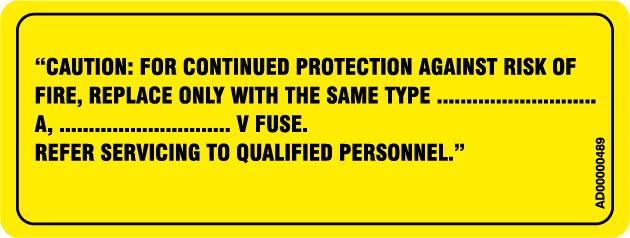
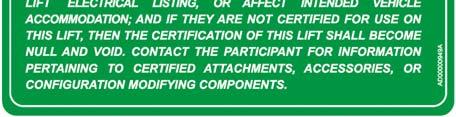
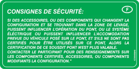
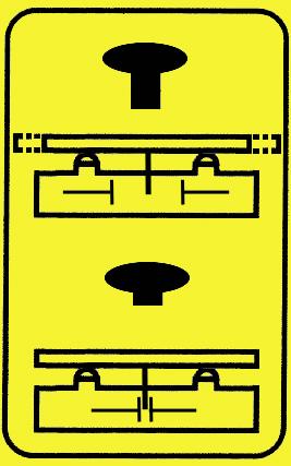
8 LABELS AND SAFETY DECALS The labels must be readable and permanently attached to the equipment. The labels that will be furnished with the equipment, together with their relevant positions, listed here below: N. LABEL DESCRIPTION 2 RISK OF ELECTRIC SHOCK 3 RISK OF EXPLOSION 4 FUSE 12 ALI GOLD LABEL 14 NOTICE 16 CAUTION WARNING SAFETY INSTRUCTIONS 17 EARTH CONNECTION 22 MAX CAPACITY 23 DO NOT STAY NEAR THE LIFT IN MOVEMENT 25 PINCH POINT HAZARD 26 LIFTING LOWERING 27 MECHANICAL SAFETY LOCKS 28 CHALLENGER SERIAL TAG 29 SLIP PLATES 30 PHOTOCELL OVERRIDE 31 LIGHT SELECTOR 34 BLEEDING/SYNCRONIZATION PROCEDURE 35 DO NOT USE BELOW GARAGE FLOOR OR GRADE LEVEL 8
9 LIFT


10 14 28 CONTROL UNIT


11 LABEL 2 LABEL 4 LABEL 2A LABEL 4A LABEL 3 LABEL 5 LABEL 3A LABEL 5A 11


12 LABEL 12 LABEL 14 LABEL 16 LABEL 14A LABEL 17 12


13 LABEL 22 LABEL 23 LABEL 25 LABEL 28 CHALLENGER SERIAL TAG LABEL 26 LABEL 29 LABEL 27 13


14 LABEL 30 LABEL 35 LABEL 31 LABEL 35A LABEL 34 14


15 OPERATION COMMANDS MS UP LK DN PO LT SP SYSTEM MAIN SWITCH: Provides power to controls when turned ON UP BUTTON: Lift rises when pressed continuously. LOCK BUTTON:: When lift is above the first lock position, the lift will lower to the nearest mechanical lock position when pressed. DOWN BUTTON: 1 By continuously pressing the DN button, the lift: a) Rises for 3-4 seconds to clear the mechanical locks. b) The lift begins lowering. PHOTOCELL OVERRIDE: If there is a difference in height of more than 50 mm, power to the motor will be cutoff. Use the PO button to exclude the photocell. By keeping the PO button pressed, it will be possible to use other buttons and light switch. LIGHT CONTROL SWITCH: Turns on lights mounted to platforms. SLIP PLATES LOCKING SYSTEM: Pushing this knob locks the slip plates in place. Pulling the knob allows the slip plates to move freely. MS UP DN SP LK LT PO 15
16 VERTICAL CLEARANCE Check the height of the area where the lift is to be installed. Clearance should be calculated based on the full raised height of the lift. Failure by purchaser to provide WARNING adequate clearance could result in unsatisfactory lift performance, property damage, or personal injury. FLOORING Be certain you have the proper concrete floor to properly handle the loaded lift. Floor should be in generally good condition with no large cracks, spalling or deterioration. Minimum requirements for concrete are 6 inches minimum depth, with steel reinforcement, 3500 psi, cured for 28 days per local commercial practice. Floor should be level within 3/8 inch over the installation area. No anchors should be installed within 6 inches of any crack, edge, or expansion joint. If these conditions cannot be met, a pad may be poured to accommodate the lift. Check with local building inspectors and/or permits office for any special instructions or approvals required for your installation. Failure by purchaser to WARNING provide the recommended mounting surface could result in unsatisfactory lift performance, property damage, or personal injury. LOCATION This lift is approved for indoor use only. ELECTRICAL REQUIREMENTS For lift installation and operation it is necessary to have a dedicated circuit with circuit breaker or time delay fuse. Refer to Fig. 15 for circuit sizing. SAFETY NOTICES AND DECALS For your safety, and the safety of others, read and understand all of the safety notices and decals included in this manual. READ ENTIRE MANUAL BEFORE ASSEMBLING, INSTALLING, OPERATING, OR SERVICING THIS EQUIPMENT. PROPER MAINTENANCE AND INSPECTION IS NECESSARY FOR SAFE OPERATION. DO NOT OPERATE A DAMAGED LIFT. Safety decals similar to those shown in this manual are found on a properly installed lift. Be sure that all safety decals have been attached to the control console of the lift. Verify that all authorized operators know the location of these decals and fully understand their meaning. Replace worn, faded, or damaged decals promptly. Do not attempt to raise a vehicle on the lift until the lift has been WARNING correctly installed and adjusted as described in this manual. RECEIVING The shipment should be thoroughly inspected as soon as it is received. The signed bill of lading is acknowledgement by the carrier of receipt in good condition of shipment covered by our invoice. If any of the goods called for on this bill of lading are shorted or damaged, do not accept them until the carrier makes a notation on the freight bill of the shorted or damaged goods. Do this for your own protection. NOTIFY Challenger Lifts AT ONCE if any hidden loss or damage is discovered after receipt. IT IS DIFFICULT TO COLLECT FOR LOSS OR DAMAGE AFTER YOU HAVE GIVEN THE CARRIER A CLEAR RECEIPT. File your claim with Challenger Lifts promptly. Support your claim with copies of the bill of lading, freight bill, and photographs, if available. HANDLING The packaged lift must only be transported and handled using dedicated hoisting equipment with a greater capacity than the lift to be handled. Lifting straps should be used during installation of lift. Weight of packaged lift and accessories can be approx 6000 lbs. ACCEPTED OILS Do not use oils with detergents. Hydraulic fluid is not provided with the lift shipment. -10 wt. anti-foam, anti-rust hydraulic / biodegradable oil -Dexron III ATF TOOLS (MINIMUM REQUIRED) a. Tape measure, 16ft b. Chalk line c. 4ft level d. 10 adjustable wrench e. Standard open end wrenches 5/16, 3/4 f. Allen wrench set g. Hammer drill with 1/4 & 1/2 diameter carbide tipped bits h. 2lb hammer i. Torque wrench: 50 foot-pounds minimum with 3/4 socket j. Screwdriver k. Long oil funnel IMPORTANT: Always wear safety glasses while installing lift. 16
 The control console can be located on the driver side or passenger side of the lift at a maximum standard distance as shown in Fig. 1. IMPORTANT: Console should be positioned so the lift operator has clear view of the vehicle and bay area during lifting/lowering.")
 Relocating the control console further away than the standard distance will require the installer to provide suitable hydraulic hoses and air lines.")
17 SURFACE & FLUSH MOUNT LAYOUT 1) Layout the service bay according to the architect s plans or owners instructions (see Fig. 1). Failure to install in this orientation can result in personal and property damage. Be certain that the proper conditions exist, see page 15. 2) The control console can be located on the driver side or passenger side of the lift at a maximum standard distance as shown in Fig. 1. IMPORTANT: Console should be positioned so the lift operator has clear view of the vehicle and bay area during lifting/lowering. Relocating the control console from the driver side to the passenger side will require moving the green hose blocks at the base of the unit to direct the hoses/lines to the opposite side. 3) Relocating the control console further away than the standard distance will require the installer to provide suitable hydraulic hoses and air lines. Additional hose covers will also be needed if installing lift in surface mount configuration. Hydraulic hoses should be 1/4" minimum ID with a minimum working pressure of 4,200 psi and a minimum burst pressure of 16,800 psi with #6 JIC fittings (1) Male x (1) Female Swivel. The air lines for the lift have outside diameters of 4mm, 6mm, and 10mm and should have a minimum working pressure of 120 psi. Maximum dimension E from Fig. 1 is 20 feet IF hose and air line extensions are used. Electrical wiring from lift should not be modified/extended for safety reasons. FLUSH MOUNT PIT REQUIREMENTS 4) PRIOR TO POURING CONCRETE, installer will need to ensure pit frame, piping, and forms conform to details shown in Fig. 3. Pit frame and temporary pit forms are NOT PROVIDED and will be the responsibility of the installer. Total pipe chase length should not exceed 13 for standard install or 20 if line extensions will be supplied by installer. 8) With the top platform assembly ready to be placed into position, place a lifting strap(s) under the assembly and carefully manuever into position. 9) Repeat for other platform assembly and remove any remaining banding/packaging. 10) Remove all electrical/hydraulic/air lines from under platforms and route to the control console. ELECTRICAL CONNECTIONS 11) Use an Allen wrench to loosen the (2) screws on the sides of the control cover of the console. 12) Ensure Main Switch located on control cover is turned to the OFF position and open the cover. Fig. 4 Main Switch 13) Route electrical lines from platform assemblies thru opening in the bottom rear of the console and thru the opening in the sidewall of the upper electrical compartment. 14) Using the numbering on each of the supplied wires, connect each to the corresponding terminal in the console as shown in Fig. 5. A small flat head screwdriver will be needed for this step. PLATFORM INSTALLATION 5) Place packaged lift onto 4x4 pieces of lumber and remove steel end brackets. 6) Remove any accessories that are packaged with the platform assemblies. 7) DO NOT cut the bands securing the bases of each assembly to the platform. These keep the scissors in a collapsed position. Fig. 5 Wiring Connections 17
 Ensure power to supply wiring is OFF before making following connections. 16) Power supply to console shall be a suitable electrical source as shown in the Fig. 15 - Electrical Wiring Diagram.")
 The air lines from the lift can be identified using the following table. Connect each air line according to Fig. 8 and Fig. 9.")
 Route hydraulic lines thru opening in the bottom rear of the console.")
18 - Each lift shall have a dedicated circuit with a double-pole breaker or time delay fuse sized according to Fig Wiring must comply with all local electrical codes. 15) Ensure power to supply wiring is OFF before making following connections. 16) Power supply to console shall be a suitable electrical source as shown in the Fig Electrical Wiring Diagram. 17) For single phase console, connect the electrical supply to the back side of the Main Switch (L2 & L3) as shown in Fig. 6. Connect the ground wire to the GREEN contactor beside the main switch. Refer to Fig. 15 for 3 phase console wiring. PNEUMATIC CONNECTIONS 20) The air lines from the lift can be identified using the following table. Connect each air line according to Fig. 8 and Fig. 9. Description Line LOCKS 6mm BLACK/WHITE SLIP PLATES 6mm BLUE AIR LIMIT SWITCH 5 (RETURN CIRCUIT) AIR LIMIT SWITCH (SEND CIRCUIT) ROLLING JACKS 4 WHITE (10mm) SUPPLY AIR CONNECTION Barb for 3/8 I.D Hose. ROLLING JACKS LOCKS Fig. 6 Power Supply Connection SEND CIRCUIT RETURN CIRCUIT HYDRAULIC CONNECTIONS 18) Route hydraulic lines thru opening in the bottom rear of the console. 19) Connect the hydraulic lines to the block connections inside the control unit, Fig. 7. NOTE: The hydraulic lines from the lift platforms can connect to either port. Fig. 8 Pneumatic Connections 21) The connection for the Slip Plates is located on the underside of the console cover as shown below. SLIP PLATES Fig. 9 Slip Plate Connection Fig. 7 Hydraulic Connections IMPORTANT: Before air supply is connected, ensure the T-fitting on the side of the platform is plugged. The fitting is used for optional Rolling Jack Airline Kit (40230-SX).
 Ensure air supply is connected and T- fitting on runway is plugged or connected to the rolling jacks with the airline kit.")


19 BLEEDING/SYNCHRONIZING 22) After adding fluid to the reservoir, turn Power on and ensure the Main Switch is turned to the ON position. 23) Ensure air supply is connected and T- fitting on runway is plugged or connected to the rolling jacks with the airline kit. NOTE: The UP, DOWN, LOCK, and PHOTOCELL OVERRIDE switches are momentary, so the function only remains energized while the button is depressed. IMPORTANT: DO NOT skip any step. A. Ensure all 3 valves are closed, Fig 10. B. Press PHOTOCELL OVERRIDE & UP until both platforms stop moving.* Note 1 C. OPEN all 3 valves. D. Press PHOTOCELL OVERRIDE & UP until both platforms stop moving. E. Bleed air from each cylinder, Fig 11. F. If platforms lower into a lock position, press UP for 5 seconds. G. Bleed cylinders until oil begins to escape. H. Press UP until both platforms stop moving. I. CLOSE all 3 valves. J. Press PHOTOCELL OVERRIDE & Notes 2,3 DOWN.* K. Repeat entire procedure.* Note 4 Note 1: If platforms do not rise after pressing UP for 30 seconds, continue to step C of procedure. Fig. 10 Valves Fig. 11 Bleed Screw Note 2: If platform(s) stop moving while lowering, OPEN all 3 valves and continue lowering. Once both pads are completely lowered, CLOSE all 3 valves and repeat the entire bleeding procedure. Note 3: With platforms completely lowered, add oil to fill reservoir. Note 4: The bleeding procedure should be performed at least 3 times and repeated until both platforms are synchronized thru the complete raising and lowering of the platforms and no air comes out of either bleed screw.
 After positioning the lift and bases, ensure the lift is level per bleow. Use a spirit level to verify that deviation in any direction does not exceed: 1/32 inch per 6 feet Proceed as follows: 1.")
20 LEVELING 24) Ensure platforms are square with one another and arranged as shown in Fig. 1 and base plates are spaced according to Fig. 2. NOTE: The (2) larger bases may need to be shifted forward or rearward. 25) After positioning the lift and bases, ensure the lift is level per bleow. Use a spirit level to verify that deviation in any direction does not exceed: 1/32 inch per 6 feet Proceed as follows: 1. Raise the lift approx 3 off the ground. 2. Place in locks using LOCK button. 3. Use the LEVELING ADJUSTERS to adjust the height of the base until the surface of the runways are level, Fig. 12. PLATFORM AND BASE LEVELING ADJUSTER Fig. 12 Leveling Adjusters 4. Use shims under bases in areas shown in Fig. 13 as needed to achieve levelness. Shims may be cut to length as needed. Fig. 13 Shimming Area 5. Ensure surface of runways are on the same plane. If not, add shims to the bases as necessary. NOTE: If more than 1/4 of shimming is required to achieve specified levelness, use grout with equivalent mechanical properties as concrete under appropriate base plates. The maximum acceptable grout height is With all bases properly adjusted and adequately supported with shims or grout, proceed with ANCHORING. 7. Once anchored, lower lift and use the LEVELING ADJUSTERS to adjust the level of the platforms at the fully lowered position. Each platform should contact (6) bolts when lowered. Tighten lock nuts when done. 8. Adjust rear runway bolt to make contact with floor when lift is completely lowered. ANCHORING 26) The anchor bolts must be installed at least 6 from any crack, edge or expansion joint. 27) Use a concrete hammer drill with a 1/2 inch carbide bit. Tip diameter should conform to ANSI Standard B (.520 to.530). Do not use excessively worn bits or bits which have been incorrectly sharpened. A core bit may be necessary if an obstruction is encountered. Never substitute with a shorter anchor. 28) Recheck the layout dimensions, Fig. 1. With lift raised, use the (4) holes in each base plate as a template. Drill through the floor if possible. 29) Vacuum dust from the hole for proper holding power. 30) Assemble washer and nut to anchor with nut just below impact section of bolt. Drive anchor into hole until nut and washer contact base. 31) Tighten anchors and recheck level. Reshim if necessary. Torque to 40 foot pounds to set anchors. 32) After control console and center hose cover are positioned, drill (4) ¼ holes in the corners and install supplied drive anchors. 33) For hose covers between control console and the lift structure, overlap sections approx 1 and drill (2) ¼ holes thru each connection as shown in Fig. 14. Total length of hose covers is approx 4 meters. Fig. 14 Hose Covers
21 OWNER/OPERATOR CHECKLIST 34) Demonstrate the operation of the lift to the owner/operator and review correct and safe lifting procedures using the Lifting It Right booklet as a guide. OPERATION PROCEDURE SAFETY NOTICES AND DECALS This product is furnished with graphic safety warning labels, which are reproduced on page 3 of these instructions. Do not remove or deface these warning labels, or allow them to be removed or defaced. For your safety, and the safety of others, read and understand all of the safety notices and decals included. OWNER/EMPLOYER RESPONSIBILITIES This lift has been designed and constructed according to ANSI/ALI ALCTV-2011 standard. The standard applies to lift manufactures, as well as to owners and employers. The owner/employer s responsibilities as prescribed by ANSI/ALI ALOIM-2008, are summarized below. For exact wording refer to the actual standard provided with this manual in the literature pack. The Owner/Employer shall insure that lift operators are qualified and that they are trained in the safe use and operation of the lift using the manufacturer s operating instructions; ALI/SM 93-1, ALI Lifting it Right safety manual; ALI/ST-90 ALI Safety Tips card; ANSI/ALI ALOIM-2008, American National Standard for Automotive Lifts-Safety Requirements for Operation, Inspection and Maintenance; ALI/WL Series, ALI Uniform Warning Label Decals/Placards; and in case of frame engaging lifts, ALI/LP-GUIDE, Vehicle Lifting Points/Quick Reference Guide for Frame Engaging Lifts. The Owner/Employer shall establish procedures to periodically inspect the lift in accordance with the lift manufacturer s instructions or ANSI/ALI ALOIM-2008, American National Standard for Automotive Lifts-Safety Requirements for Operation, Inspection and Maintenance; and the employer shall insure that the lift inspectors are qualified and that they are adequately trained in the inspection of the lift. The Owner/Employer shall establish procedures to periodically maintain the lift in accordance with the lift manufacturer s instructions or ANSI/ALIOIM- 2008, American National Standard for Automotive Lifts-Safety Requirements for Operation, Inspection and Maintenance; and the employer shall insure that the lift maintenance personnel are qualified and that they are adequately trained in the maintenance of the lift. The Owner/Employer shall maintain the periodic inspection and maintenance records recommended by the manufacturer or ANSI/ALI ALOIM-2008, American National Standard for Automotive Lifts-Safety Requirements for Operation, Inspection and Maintenance. The Owner/Employer shall display the lift manufacturer s operating instructions; ALI/SM 93-1, ALI Lifting it Right safety manual; ALI/ST-90 ALI Safety Tips card; ANSI/ALI ALOIM-2008, American National Standard for Automotive Lifts-Safety Requirements for Operation, Inspection and Maintenance; and in the case of frame engaging lift, ALI/LP-GUIDE, Vehicle Lifting Points/Quick Reference Guide for Frame Engaging Lifts; in a conspicuous location in the lift area convenient to the operator. LIFTING A VEHICLE 1) Ensure that the lift is completely lowered. 2) Ensure slip plates and turn plates are in the locked position so they do not move during the entrance of the vehicle onto the lift. 3) Drive vehicle on the lift to the desired location ensuring it is centered from side to side. 4) Place wheel chocks behind rear tires if there is more than 1 gap from tire to ramp. DO NOT EXCEED 7000 POUNDS PER PAD. DO NOT ATTEMPT TO LIFT THE VEHICLE WITH ONLY ONE RUNWAY, AS THIS WILL VOID THE WARRANTY The vehicle should remain level during lifting. 5) Raise the vehicle to a height above the desired working height. 6) Press the LOCK button to lower into the mechanical locks. Ensure the safety locks on both platforms engage. The vehicle should remain level when both latches are engaged. If one side engages and the other continues to descend, stop lowering the lift and check synchronization and photocell operation before continuing. Always lower lift into locks before entering the area beneath the vehicle. LOWERING A VEHICLE 1) Ensure that the area under the vehicle is clear of personnel and tools. 2) Lower the vehicle by pressing the DOWN button. Lift will raise for 3-4 seconds to clear mechanical locks and then begin to lower. If pads do not stay level during lowering, discontinue lowering and check the lock mechanisms for proper functioning. 3) Once completely lowered, remove the wheel chocks and ensure slip plates and turn plates are in the locked position before removing vehicle from the lift. 21


22 PHOTOCELL NORMAL STATUS GREEN LED: ON YELLOW LED: ON STOP STATUS GREEN LED: ON YELLOW LED: OFF Place an object above reflector and move downwards check when the YELLOW LED is switched off. mark the position. REFLECTOR POSITIONING CHECK place an object below reflector and move upwards check when the YELLOW LED is switched off. mark the position. the work field is between the two marks. adjust photocell so work field is centered on Reflector. PHOTOCE Functioning test Interrupt photocell beam using an object and check: A With vehicle lift stopped The lift can be not activated from the control panel B With vehicle lift moving The lift movement stops 22


23 SAFETY STANDARDS FOR MAINTENANCE Before starting the maintenance and inspection procedures, always perform the following operations: Always wear adequate clothing and accident-prevention equipment during the various phases of maintenance. In particular: - Overalls with snug-fitting cuffs - Goggles/safety glasses - Gloves - Helmet - Dust mask - Safety Harness - Safety shoes Always use equipment that is in good condition Have on hand a portable lamp to light the areas under maintenance. MACHINE OUT OF SERVICE machine undergoing maintenance Identify system cut-off switches; Cut off power to the electrical system before performing any operation near or on moving mechanical parts or before performing any operation on powered parts of the system. Use Lock Out/Tag Out procedures to lock the cut-off switch in the open position using a padlock. Make certain that the system is not repowered while maintenance work is in progress. NEVER operate directly on control breaker NEVER lubricate parts while they are moving Post signs reading DO NOT PERFORM ANY OPERATIONS, Machine Undergoing Maintenance During maintenance or replacement of hydraulic system components, Always prevent any foreign bodies, even very small ones, from entering the circuit as this could lead to malfunction. Vent hydraulic pressure before loosening the connections 23
24 MAINTENANCE/ INSPECTION SCHEDULE WHAT WHERE MACHINE STATUS HOW USE Daily SYNCHRONIZATION PLATFORMS IN MOTION VISUAL INSPECTION SYNC PROCEDURE Daily MECHANICAL LOCKS UNDER PLATFORMS IN MOTION VISUAL INSPECTION Weekly PHOTOCELL REAR END OF PLATFORM AGIP LH 46 Annually TANK HYDRAULIC UNIT OFF OIL CHANGE ESSO OSO H 46 Periodically check the electrical safety devices and report any faults to the Challenger Lifts Technical Support. -To avoid personal injury, permit only qualified personnel to perform maintenance on this equipment. Maintenance personnel should follow lockout/ta instructions per ANSI Z The following maintenance points are suggested as the basis of a routine maintenance program. The actual maintenance program should be tailore the installation. See ANSI/ALI ALOIM booklet for periodic inspection checklist and maintenance log sheet. -Replace all Safety, Warning or Caution Labels if missing or damaged (See page 8.) IN MOTION VISUAL INSPECTION See PHOTOCELL Weekly AIR CONNECTIONS PNEUMATIC CIRCUIT IN MOTION VISUAL INSPECTION Weekly HYDRAULIC CONNECTIONS HYDRAULIC CIRCUIT FULLY RAISED VISUAL INSPECTION Bi-Weekly SLIDE BLOCKS BASES & PLATFORMS FULLY RAISED GREASE MOLYCOTE G-4700 Bi-Weekly PINS AND SUPPORTS STRUCTURE OFF GREASE MOLYCOTE G


25 LUBRICATION POINTS (repeat symmetrically on both sides of the lift) 25
26 LUBRICANT: INFORMATION AND WARNINGS Disposal of used oil Do not pour used oil into the sewers, ditches or bodies of water. Keep it in special containers and deliver it to companies specialized in such disposal. Leaks Cover any lubricant leaks with soil, sand or other absorbent material. The contaminated area must be degreased with solvents and without leaving puddles or allowing vapours to form. The materials used for cleaning must be disposed of in compliance with current regulations. First aid Ingestion: contact the nearest emergency centre and provide all information on the type of oil ingested Inhalation: in the case of exposure to high concentrations of fumes or oil vapours, bring the wounded outside and contact the nearest emergency centre Eyes: rinse thoroughly with water and contact the nearest emergency centre Skin: wash with soap and water. Precautions Avoid contact with the skin Avoid the formation or spread of vapours in the environment Prevent spills Wash frequently without using aggressive cleansers Do not dry hands with rags soiled with oil Change any clothing that is dirty or greasy and always change clothes at the end of the workday Never smoke or eat with greasy hands Wear the following personal protection equipment: - Gloves resistant to mineral oils, and with internal lining - Eye protection vs. spraying of mineral oil - Resistant apron vs. sprays 26


 and allow")

27 MANUAL LOWERING Operations to be performed to lower raised platform in the event of loss of power to equipment: A EV1 Using pump handle, pump until the mechanical locks are no longer engaged. Activate Lock Release using the dedicated manual valve on solenoid valve EV2 (turn screw 90 ). ENSURE THAT MECHANICAL LOCKS ARE OPEN. Activate solenoid valve EV1 (see photograph: A or B or C) and allow the lift to lower; to restore, return the manual command of valve EV2 to its position and tighten the knurled pins. EV2 B C SCREW Manual Pump EV1 27
28 TROUBLESHOOTING OPERATIONS WHAT HAPPENS WHERE CHECK The lift does not rise and the motor does not start The lift does not rise and the motor starts. The lift does not lower and the pressure is normal. a. FUSES b. THERMAL RELAY c. TRANSFORMER d. MOTOR e. MAIN CONTACTOR f. PHOTOCELL a. HYDRAULIC PUMP b. LOWERING VALVE c. LIMIT VALVE d. MOTOR a. PHOTOCELLS b. TRANSFORMER c. PARACHUTE VALVE d. ELECTRIC VALVE e. MECHANICAL SAFETY DEVICES f. LOCK RELEASE VALVE a.1. line fuse blown. a volt fuse blown. b.1. thermal relay tripped, reset. c.1. transformer failure, does not emit 24 volt. d.1. motor failure. e.1. contactor C1 failure f.1. photocell fault. f.2. photocells out of reading range a.1. o-ring seal broken. a.2. key broken. a.3. pickup tube broken. a.4. clamping screws loose. a.5. oil leakage. a.6. check the pressure value b.1. lowering valve stuck open. c.1.limit valve broken. d.1. Check that the motor turns in the direction shown by the arrow. a.1. photocell fault. a.2. photocells out of reading range b.1. transformer failure, does not emit 24 volt. c.1. check the parachute valves on the bottom of the dual effect cylinders. d.1. lowering valve blocked. d.2. lowering valve coil failure. e.1. mechanical safety devices mechanically blocked. f.1. air blocked (does not open the mechanical safety devices). f.2. valve requires power. 28
29 Each lift shall have a dedicated circuit with a double pole breaker or time-delay fuse rated at: 1 Phase: 30 AMP 3 Phase: 20 AMP 3 Phase 230VAC 50/60Hz 1 Phase VAC 60Hz Fig. 15 Electrical Wiring Diagram 29
30 Fig. 16 Hydraulic Diagram 30
31 Fig. 17 Pneumatic Diagram 31


32 PARTS BREAKDOWN
33 Item Part Number Quantity Description Transformer Fuse Contactor (1ph) 2 (3ph) Magnetothermic Switch Main Switch Terminal Board Contactors PLC AC/DC Transformer NO Contacts Push Button Lights Control Switch Pneumatic Valve w/ Knob Pneumatic Tee Fitting Extension mm Tube, 14M Long, Blue Turn Knob, Red Replace all worn, damaged, or broken parts with parts approved by Challenger Lifts Inc. or with parts meeting Challenger Lifts Inc. specifications. Contact your local Challenger Lifts Parts Distributor for pricing and availability. (Call Challenger Lifts Inc. (502) for the Parts Distributor in your area) 33


34
35 ITEM PART NUMBER QTY. DESCRIPTION Power Unit Assembly Pressure Relief Valve Check Valve Manual pump with Lever Lowering Valve Throttling Valve Oil Divider Cylinder Hydraulic Block Relief valve, 350 BAR Relief valve, 110 BAR Ball Valve Return Tube, 8mm O.D Hydraulic Hose, Straight Fittings Main Supply Hose Tee Fitting #6JIC x BSPP Straight Fitting Push Lock Elbow Hydrualic Hose, Elbow Power Unit Fitting Tee Fitting Straight Fitting Replace all worn, damaged, or broken parts with parts approved by Challenger Lifts Inc. or with parts meeting Challenger Lifts Inc. specifications. Contact your local Challenger Lifts Parts Distributor for pricing and availability. (Call Challenger Lifts Inc. (502) for the Parts Distributor in your area) 35


36
37 ITEM PART NUMBER Qty. Description Lock Release Solenoid Valve, 24V Lock Release Air Cylinder Slip Plate Lock Cylinder Protective Cap Pressure Switch mm Push Lock Fitting Push Lock Elbow Tee Fitting Tee Fitting Union Fitting mm Push Lock Fitting mm Push Lock Fitting mm Push Lock Ffitting mm Spiral Tube 15 DX mm x 4mm Push Lock Reducer mm Tube, 14M Long Microswitch mm Tube, 8M Long mm Push Lock Y-Union (NOT SHOWN) Tee Fitting, ¼ FNPT mm Push Lock Elbow mm Tube, 14M Long Hose Barb Fitting Pneumatic Manifold Block #6JIC x BSPP Straight Fitting Long Hydraulic Hose, 236 Replace all worn, damaged, or broken parts with parts approved by Challenger Lifts Inc. or with parts meeting Challenger Lifts Inc. specifications. Contact your local Challenger Lifts Parts Distributor for pricing and availability. (Call Challenger Lifts Inc. (502) for the Parts Distributor in your area) 37

38
39 ITEM PART NUMBER QTY. DESCRIPTION Rear Base Front Base Capture Plate Limit Switch Tab 42 X M16 Hex Nut M16 x 40 Hex Bolt M8 x 30 Flat Head Screw M4 Flat Washer M4 x 10 Pan Head Screw Straight Hose Cover Deg. Hose Cover / Shim KIT 68 00A mm thk. shim 10 3mm thk. shim Replace all worn, damaged, or broken parts with parts approved by Challenger Lifts Inc. or with parts meeting Challenger Lifts Inc. specifications. Contact your local Challenger Lifts Parts Distributor for pricing and availability. (Call Challenger Lifts Inc. (502) for the Parts Distributor in your area) 39

40 40
41 ITEM PART NUMBER QTY. DESCRIPTION Inner Scissor Weldment Outer Scissor Weldment Lifting Cylinder Lower Slide Block Upper Slide Block Safety Lock Arm Safety Lock Base mm Center Pin mm Cylinder Base Pin mm Cylinder Rod Pin Anti Rotation Plate Bushing Lock Release Cylinder Bushing Bushing mm Snap Ring M10 x 30 FHSCS M8 x 20 Cone Point Set Screw M6 Flat Washer 36 X M6 x 20 Hex Bolt 37 X M6 Hex Nut mm Snap Ring Replace all worn, damaged, or broken parts with parts approved by Challenger Lifts Inc. or with parts meeting Challenger Lifts Inc. specifications. Contact your local Challenger Lifts Parts Distributor for pricing and availability. (Call Challenger Lifts Inc. (502) for the Parts Distributor in your area) 41
42
43 43
44 ITEM PART NUMBER QTY. DESCRIPTION Standard Ramp Driver Side Platform Filler Platform Plate Plate Extended Ramp (Optional) Wheel Stop Plastic Sheet Rear Slip Plate Flush Mount Plate (Optional) Flush Mount Spacer (Optional) Slip Plate Locking Cylinder 38 VS M8 x 12 Flat Head Screw 39 X M16 Hex Nut M16 x 70 Hex Bolt 41 MR M10 x 20 Hex Bolt M8 Lock Nut (Optional) 48 Q4P M8 x 20 SHCS (Optional) Platic Pad Plastic Roller Roller Pin mm Snap Ring Replace all worn, damaged, or broken parts with parts approved by Challenger Lifts Inc. or with parts meeting Challenger Lifts Inc. specifications. Contact your local Challenger Lifts Parts Distributor for pricing and availability. (Call Challenger Lifts Inc. (502) for the Parts Distributor in your area) 44

45 ITEM PART NUMBER QTY. DESCRIPTION Bushing Bushing Parachute Valve Bleed Screw Greasing nipple Greasing nipple Replace all worn, damaged, or broken parts with parts approved by Challenger Lifts Inc. or with parts meeting Challenger Lifts Inc. specifications. Contact your local Challenger Lifts Parts Distributor for pricing and availability. (Call Challenger Lifts Inc. (502) for the Parts Distributor in your area) 45
MODEL QMR6 PORTABLE MID-RISE LIFT 6,000 lb Capacity 1500 lb Per Arm INSTALLATION, OPERATION AND MAINTENANCE MANUAL
 MODEL QMR6 PORTABLE MID-RISE LIFT 6,000 lb Capacity 1500 lb Per Arm INSTALLATION, OPERATION AND MAINTENANCE MANUAL IMPORTANT!!! READ THIS MANUAL COMPLETELY BEFORE INSTALLING OR OPERATING THE LIFT 200 CABEL
INSTALLATION, OPERATION & MAINTENANCE MANUAL
 INSTALLATION, OPERATION & MAINTENANCE MANUAL Two Post Surface Mounted Lift MODEL X10 10,000 LBS. CAPACITY 2500 LBS. PER ARM 200 Cabel Street, P.O. Box 3944 Louisville, Kentucky 40201-3944 Email:sales@challengerlifts.com
Model Q4P12E and Q4P12X
 INSTALLATION, OPERATION & MAINTENANCE MANUAL Four Post Surface Mounted Lift Model Q4P2E and Q4P2X Closed Front (2,000 lb Capacity) 200 Cabel Street, P.O. Box 3944 Louisville, Kentucky 4020-3944 Email:sales@Qualitylifts.com
Model Q4P12E and Q4P12X
 INSTALLATION, OPERATION & MAINTENANCE MANUAL Four Post Surface Mounted Lift Model Q4P2E and Q4P2X Closed Front (2,000 lb Capacity) 200 Cabel Street, P.O. Box 3972 Louisville, Kentucky 4020-3972 Email:sales@Qualitylifts.com
INSTALLATION, OPERATION & MAINTENANCE MANUAL
 INSTALLATION, OPERATION & MAINTENANCE MANUAL Four Post Surface Mounted Lift Model 4P14EFX and 4P14XFX Closed Front (14,000 lb Capacity) 200 Cabel Street, P.O. Box 3944 Louisville, Kentucky 40201-3944 Email:sales@challengerlifts.com
Two Post Surface Mounted Lift 12,000 LBS. CAPACITY 3000 LBS. PER ARM
 INSTALLATION, OPERATION & MAINTENANCE MANUAL Two Post Surface Mounted Lift MODEL EELR537A 12,000 LBS. CAPACITY 3000 LBS. PER ARM Snap-On Equipment 309 Exchange Avenue, Conway, Arkansas, 72032 Tel: 501-450-1500
Two Post Surface Mounted Lift 10,000 LBS. CAPACITY 2500 LBS. PER ARM
 INSTALLATION, OPERATION & MAINTENANCE MANUAL Two Post Surface Mounted Lift MODEL LE10 10,000 LBS. CAPACITY 2500 LBS. PER ARM 2311 South Park Rd Louisville, Kentucky 40219 Email:sales@challengerlifts.com
MODEL QFP09. Two Post Surface Mounted Lift. Installation, Operation & Maintenance Manual. Office / Fax
 Installation, Operation & Maintenance Manual Two Post Surface Mounted Lift MODEL QFP09 9,000 LBS. CAPACITY 2,250 LBS. PER ARM 200 Cabel Street, P.O. Box 3972 Louisville, Kentucky 40201-3972 Email:sales@qualitylifts.com
Model OE Four Post Surface Mounted Lift. Office / Fax IMPORTANT: READ THIS MANUAL COMPLETELY BEFORE
 Four Post Surface Mounted Lift Model OE-40000 Open Front (,000 lb Capacity) 0 Cabel Street, P.O. Box 3944 Louisville, Kentucky 40-3944 Email:sales@challengerlifts.com Web site:www.challengerlifts.com Office
Challenger Lifts, Inc. MODEL 12000
 Challenger Lifts, Inc. MODEL 12000 TWO POST SURFACE MOUNTED LIFT OPERATION, INSTALLATION & MAINTENANCE MANUAL IMPORTANT READ THIS MANUAL COMPLETELY BEFORE INSTALLING OR OPERATING THE LIFT 200 CABEL STREET,
Installation, Operation & Maintenance Manual. Four Post Surface Mounted Lift. Model Open Front (15,000 lb Capacity)
") Installation, Operation & Maintenance Manual Four Post Surface Mounted Lift Model 405 Open Front (5,000 lb Capacity) 23 South Park Rd Louisville, Kentucky 40206 Email:sales@challengerlifts.com Web site:www.challengerlifts.com
Installation, Operation & Maintenance Manual Four Post Surface Mounted Lift Model 405 Open Front (5,000 lb Capacity) 23 South Park Rd Louisville, Kentucky 40206 Email:sales@challengerlifts.com Web site:www.challengerlifts.com
Challenger Lifts, Inc. MODELS & 18000
 Challenger Lifts, Inc. MODELS 15000 & 18000 TWO POST SURFACE MOUNTED LIFT OPERATION, INSTALLATION & MAINTENANCE MANUAL IMPORTANT READ THIS MANUAL COMPLETELY BEFORE INSTALLING OR OPERATING THE LIFT 200
Two Post Surface Mounted Lift 12,000 LBS. CAPACITY 3000 LBS. PER ARM
 INSTALLATION, OPERATION & MAINTENANCE MANUAL Two Post Surface Mounted Lift MODEL Q12 12,000 LBS. CAPACITY 3000 LBS. PER ARM 200 Cabel Street, P.O. Box 3944, Louisville, Kentucky 40206 Email:sales@qualitylifts.com
Installation Instructions X-Force UTV Lift (000 Series) Capacity 2,275 lbs (1,035 kg)
 Capacity 2,275 lbs (1,035 kg)") Installation Instructions X-Force UTV Lift (000 Series) Capacity 2,275 lbs (1,035 kg) Read entire manual before assembling, installing, operating, or servicing this equipment. LP20640 IN20793 September
Installation Instructions X-Force UTV Lift (000 Series) Capacity 2,275 lbs (1,035 kg) Read entire manual before assembling, installing, operating, or servicing this equipment. LP20640 IN20793 September
MODEL Two Post Surface Mounted Lift. Office / Fax Installation, Operation & Maintenance Manual
 Installation, Operation & Maintenance Manual Two Post Surface Mounted Lift MODEL 15000 15,000 LB CAPACITY - 3750 LB PER ARM MODEL 18000 18,000 LB CAPACITY 4500 LB PER ARM 200 Cabel Street, P.O. Box 3944
Installation, Operation & Maintenance Manual. Surface Mounted Lift 10,000 LBS. CAPACITY 2500 LBS. PER ARM
 Installation, Operation & Maintenance Manual VersymmetricTM Two Post Surface Mounted Lift MODEL CL10 10,000 LBS. CAPACITY 2500 LBS. PER ARM 200 Cabel Street, P.O. Box 3944 Louisville, Kentucky 40201-3944
MODEL CL10. Versymmetric Two Post. Surface Mounted Lift. Installation, Operation & Maintenance Manual
 Installation, Operation & Maintenance Manual Versymmetric Two Post Surface Mounted Lift MODEL CL10 10,000 LBS. CAPACITY 2500 LBS. PER ARM 200 Cabel Street, P.O. Box 3944 Louisville, Kentucky 40201-3944
Models Q4P09H & Q4P09X
 Installation, Operation & Maintenance Manual Four Post Surface Mounted Lift Models Q4P09H & Q4P09X (9,000 lb Capacity) 200 Cabel Street, P.O. Box 3944 Louisville, Kentucky 40201-3944 Email:sales@qualitylifts.com
Models Q4P07. Four Post Surface Mounted Lift. Installation, Operation & Maintenance Manual IMPORTANT: READ THIS MANUAL COMPLETELY BEFORE
 Installation, Operation & Maintenance Manual Four Post Surface Mounted Lift Models Q4P07 (7,000 lb Capacity) 200 Cabel Street, P.O. Box 3972, Louisville, Kentucky 40201-3972 Email:sales@qualitylifts.com
MODEL CL10. Versymmetric Two Post. Surface Mounted Lift. Installation, Operation & Maintenance Manual
 Installation, Operation & Maintenance Manual Versymmetric Two Post Surface Mounted Lift MODEL CL10 10,000 LBS. CAPACITY 2500 LBS. PER ARM 200 Cabel Street, P.O. Box 3944 Louisville, Kentucky 40201-3944
9,000 LBS. CAPACITY 2250 LBS. PER ARM
 INSTALLATION NSTALLATION,, OPERATION O & MAINTENANCE M MANUAL & M VersymmetricTM Two Post Surface Mounted Lift MODEL CL9 9,000 LBS. CAPACITY 2250 LBS. PER ARM 200 Cabel Street, P.O. Box 3944 Louisville,
MODEL CL10. VersymmetricTM Two Post. Surface Mounted Lift. Installation, Operation, & Maintenance Manual
 Installation, Operation, & Maintenance Manual VersymmetricTM Two Post Surface Mounted Lift MODEL CL10 WITH DUAL PENDANT CONTROL 10,000 LBS. CAPACITY 2500 LBS. PER ARM 200 Cabel Street, P.O. Box 3944 Louisville,
INSTALLATION, OPERATION & MAINTENANCE MANUAL
 INSTALLATION, OPERATION & MAINTENANCE MANUAL Four Post Surface Mounted Lift/Platform Lube Rack System MODEL MDTR3 SHOWN (RECESSED TRIPLE) Model MDT Modular Drive Thru (12,000 lb Capacity) 200 Cabel Street,
Models Q4P09H, Q4P09X & Q4P09W
 Installation, Operation & Maintenance Manual Four Post Surface Mounted Lift Models Q4P09H, Q4P09X & Q4P09W (9,000 lb Capacity) 200 Cabel Street, P.O. Box 3972, Louisville, Kentucky 40201-3972 Email:sales@qualitylifts.com
2-Post Lift Operations and Maintenance Manual
 2-Post Lift Operations and Maintenance Manual Table Of Contents Safety Instructions... 2 Owner/Employer Responsibilities / Operating Conditions... 3 Operating Instructions... 4 Maintenance Instructions...
If facility voltage is different, refer to set-up instructions. IMPORTANT This lift is wired and adjusted to operate at 230 volts.
 MODEL 40/50K Installation And Owner s Manual (000Series) Capacity 40,000 lbs. (20,000 lbs. per axle) Capacity 50,000 lbs. (25,000 lbs. per axle) Four Post Surface Mounted Lift IMPORTANT This lift is wired
Installation Instructions Capacity 10,000 lbs. (100 Series Lift)
") Installation Instructions Capacity 10,000 lbs. (100 Series Lift) IMPORTANT Reference ANSI/ALI ALIS, Safety Requirements for Installation and Service of Automotive Lifts before installing lift. OPERATING
Installation Instructions Capacity 10,000 lbs. (100 Series Lift) IMPORTANT Reference ANSI/ALI ALIS, Safety Requirements for Installation and Service of Automotive Lifts before installing lift. OPERATING
Cargolift 85 Pv Repair. Cargolift 90 Sa Standard. Cargolift 120 Saav Jumbo. Cargolift 120 F Drive-on IMPORTANT
 Installation, Operation and Maintenance Manual For Cargolift 85 Pv Repair Cargolift 90 Sa Standard Cargolift 120 Saav Jumbo Cargolift 120 F Drive-on IMPORTANT Read this manual throughoutly before installing,
Model QML1750A. Motorcycle / ATV Lift. (1,750 lb capacity) INSTALLATION, OPERATION AND MAINTENANCE MANUAL
 INSTALLATION, OPERATION AND MAINTENANCE MANUAL") Model Motorcycle / ATV Lift (1,750 lb capacity) INSTALLATION, OPERATION AND MAINTENANCE MANUAL 200 Cabel Street, P.O. Box 3972, Louisville, Kentucky 40206 Email: sales@qualitylifts.com Web site: www.qualitylifts.com
Model Motorcycle / ATV Lift (1,750 lb capacity) INSTALLATION, OPERATION AND MAINTENANCE MANUAL 200 Cabel Street, P.O. Box 3972, Louisville, Kentucky 40206 Email: sales@qualitylifts.com Web site: www.qualitylifts.com
BLAZER 9000 LUBE LIFT OPERATOR AND PARTS MANUAL
 BLAZER 9000 LUBE LIFT OPERATOR AND PARTS MANUAL Blazer 9000 Lube Lift Operator s Manual Note: Instructions must be read thoroughly before installing, operating, or maintaining the lift. Devon Lube Center
Read this entire manual before operation begins.
 Read this entire manual before operation begins. Record below the following information which is located on the serial number data plate. Serial No. Model No. Date of Installation Contents Specifications.............
Drop Tail Motorcycle Lift 1,000 lbs. capacity Installation, Safety, Operation, Maintenance
 Drop Tail Motorcycle Lift 1,000 lbs. capacity Installation, Safety, Operation, Maintenance Entire contents 2009 by Direct Lift. All rights reserved. IN50012 CO7338.1 Rev. B 03/30/2009 Inspection upon receipt
MIDRISE MODEL SM60F_1 // SM60F_A 6,500 LB. CAPACITY
 INSTALLATION and OPERATION MANUAL READ THIS INSTRUCTION MANUAL THOROUGHLY BEFORE INSTALLING, OPERATING, SERVICING OR MAINTAINING THE LIFT. SAVE THIS MANUAL. NOV 2007 REV.B MIDRISE MODEL SM60F_1 // SM60F_A
SCISSOR LIFT Model MR6K-38 /161108A 6,000lb Capacity Operation Manual
 SCISSOR LIFT Model MR6K-38 /161108A 6,000lb Capacity Operation Manual (Version A) 2009. Apr. CONTENT 1. Safety Note, Caution and Warning Important Information Safety Instructions 2. Technical Manual Product
Motorcycle Lift 1,000 lbs. capacity Installation, Safety, Operation, Maintenance
 Motorcycle Lift 1,000 lbs. capacity Installation, Safety, Operation, Maintenance Entire contents 2008 by RL Consolidated, Inc. All rights reserved. 994358 CO7297 Rev. F 12/17/2008 Inspection upon receipt
ATO7 (100 Series Lifts)
") O PE ATO7 (100 Series Lifts) Capacity 7000 lbs. (3181 kg) 1750 lbs. (795.25 kg) per arm R A TI O N & M AI N TE N A N N CE Table Of Contents Safety Instructions... 2 Owner/Employer Responsibilities / Operating
O PE ATO7 (100 Series Lifts) Capacity 7000 lbs. (3181 kg) 1750 lbs. (795.25 kg) per arm R A TI O N & M AI N TE N A N N CE Table Of Contents Safety Instructions... 2 Owner/Employer Responsibilities / Operating
INSTALLATION AND OPERATION MANUAL
 AIR-HYDRAULIC ROLLING JACKBEAM CAPACITY: 5000 LBS. MODELS: EELR503A INSTALLATION AND OPERATION MANUAL READ ALL INSTRUCTIONS THOROUGHLY BEFORE INSTALLING, OPERATING, SERVICING, OR MAINTAINING THE LIFT.
Read this entire manual before operation begins.
 Read this entire manual before operation begins. Record below the following information which is located on the serial number data plate. Serial No. Model No. Date of Installation Contents Specifications.............
Read this entire manual before operation begins.
 Read this entire manual before operation begins. Record below the following information which is located on the serial number data plate. Serial No. Model No. Date of Installation Contents Specifications.............
TWO POST LIFT INSTALLATION AND OWNERS MANUAL
 TWO POST LIFT INSTALLATION AND OWNERS MANUAL DP15, DP15-2 Capacity 15,000 lbs. 1. TABLE OF CONTENTS 2. Important Information.. 2 3. Section 1 Owner s Manual Safety Instructions... 3 Monthly Maintenance...
CONTENTS. Product Features and Specifications Installation Requirement Installation Exploded View Operation Instruction...
 1 CONTENTS Product Features and Specifications... 3 Installation Requirement... 5 Installation... 6 Exploded View... 20 Test... 22 Operation Instruction... 25 Maintenance... 26 Trouble Shooting... 27 Parts
Read this entire manual before operation begins.
 Read this entire manual before operation begins. Record below the following information which is located on the serial number data plate. Serial No. Model No. Date of Installation Contents Specifications.............
READ THIS MANUAL BEFORE INSTALLATION AND/OR OPERATION! WARNING:
 1 READ THIS MANUAL BEFORE INSTALLATION AND/OR OPERATION! This is a vehicle lift operation manual and no attempt is made or implied herein to instruct the user in lifting methods particular to an individual
SPOA10NB, SPOA10, SPO10 ( Series Lifts) SPOA7, SPOA9, SPO9 (500 Series Lifts)
 SPOA7, SPOA9, SPO9 (500 Series Lifts)") O PE SPOA10NB, SPOA10, SPO10 (200-700 Series Lifts) SPOA7, SPOA9, SPO9 (500 Series Lifts) SPOA7 Capacity 7,000 lbs. SPOA9, SPO9 Capacity 9,000 lbs. SPOA10NB, SPOA10, SPO10 Capacity 10,000 lbs. R A TI O
O PE SPOA10NB, SPOA10, SPO10 (200-700 Series Lifts) SPOA7, SPOA9, SPO9 (500 Series Lifts) SPOA7 Capacity 7,000 lbs. SPOA9, SPO9 Capacity 9,000 lbs. SPOA10NB, SPOA10, SPO10 Capacity 10,000 lbs. R A TI O
Atlas PV-9WP Addendum
 Atlas PV-9WP Addendum 9,000 lb. Capacity Two-Post Overhead Lift The Atlas PV-9WP above ground hoist is 6 inches wider than the Atlas PV-9P, giving it an overall width of 141 (11 9 ) and a drive thru width
AUG 2011, REV.B
 6-4041 AUG 2011, REV.B 1. 1 2. OWNER / EMPLOYER OBLIGATIONS 1. The Owner/Employer shall ensure that lift operators are qualified and that they are trained in the safe use and operation of the lift using
INSTALLATION AND OPERATION MANUAL
 6,000 LB. CAPACITY / 2722 KG. Mid-RISE SCISSOR LIFT Models: MDS-6K MDS-6KF IMPORTANT SAFETY INSTRUCTIONS SAVE THESE INSTRUCTIONS Please read THE ENTIRE CONTENTS OF THIS MANUAL prior to installation AND
SPO15, SPO18 I N S T A L L A T I O N I N S T R U C T I O N S
 SPO15, SPO18 Sprinter SPO15 (3A0 Lifts) Capacity 11,000 lbs. Standard SPO15 (300 Series Lifts) Capacity 15,000 lbs. Standard SPO18 (300 Series Lifts) Capacity 18,000 lbs. SPO15 (31A0 Lifts) Capacity 14,300
Installation Instructions Capacity 10,000 lbs. DP10 (200 Series Lift)
") Installation Instructions Capacity 10,000 lbs. DP10 (200 Series Lift) IMPORTANT Reference ANSI/ALI ALIS, Safety Requirements for Installation and Service of Automotive Lifts before installing lift. OPERATING
Installation Instructions Capacity 10,000 lbs. DP10 (200 Series Lift) IMPORTANT Reference ANSI/ALI ALIS, Safety Requirements for Installation and Service of Automotive Lifts before installing lift. OPERATING
CONTENTS. Product Features and Specifications...1. Installation Requirement Steps of Installation.. 5. Exploded View Test Run...
 CONTENTS Product Features and Specifications...1 Installation Requirement... 3 Steps of Installation.. 5 Exploded View...18 Test Run...21 Operation Instruction...22 Maintenance... 23 Trouble Shooting...
MID RISE. INSTALLATION and OPERATION MANUAL MODEL 6000A // 6000E 6,000 LB. CAPACITY. READ and SAVE THIS INSTRUCTION MANUAL
 INSTALLATION and OPERATION MANUAL MID RISE MODEL 6000A // 6000E 6,000 LB. CAPACITY READ and SAVE THIS INSTRUCTION MANUAL AUGUST 2005 6-0944 6500 Millcreek Drive Mississauga, Ontario Canada L5N 2W6 1-800-268-7959
Installation, Operation & Maintenance Manual MODEL RJ9A / RJ9S. (Model Series 4-Post only) 9,000 lbs Capacity
 9,000 lbs Capacity") Installation, Operation & Maintenance Manual MODEL RJ9A / RJ9S ROLLING JACK (Model 44018 Series 4-Post only) 9,000 lbs Capacity 200 Cabel Street, P.O. Box 3944 Louisville, Kentucky 40201-3944 Email: sales@challengerlifts.com
Installation, Operation & Maintenance Manual MODEL RJ9A / RJ9S ROLLING JACK (Model 44018 Series 4-Post only) 9,000 lbs Capacity 200 Cabel Street, P.O. Box 3944 Louisville, Kentucky 40201-3944 Email: sales@challengerlifts.com
SL210i/SL212i/SL19i. Table Of Contents
 SL210i/SL212i/SL19i (700 Series) SL19i Capacity 9,000 lbs. SL210i Fixed Pad Capacity 9,000 lbs. SL210i Capacity 10,000 lbs. SL212i Capacity 12,000 lbs. Table Of Contents Owner/Employer Responsibilities...
Installation and Operation Manual
 1645 Lemonwood Dr. Santa Paula, CA, 93060 USA Toll Free (800) 253-2363 Tel: (805) 933-9970 bendpak.com Low-Rise Pit Lift Installation and Operation Manual Manual P/N 5900022 Manual Revision A3 September
Drop Tail Motorcycle Lift 1,000 lbs. capacity Installation, Safety, Operation, Maintenance
 Drop Tail Motorcycle Lift 1,000 lbs. capacity Installation, Safety, Operation, Maintenance Entire contents 2011 by Vehicle Service Group. All rights reserved. IN50012 CO7932 Rev. C 04/20/2011 Inspection
ATD2P11BS. Two-Post Clear Floor Bi-Symmetric Automotive Lift. Installation & Operation Manual. 11,000 lbs. Capacity. (2,750 lbs.
 Two-Post Clear Floor Bi-Symmetric Automotive Lift 11,000 lbs. Capacity (2,750 lbs. Max per Arm) Installation & Operation Manual 1. Safety Information 1.1 Note, Caution and Warning 1.2 Important Information
CONTENTS. Product Features and Specifications Installation Requirement Steps of Installation 4. Exploded View Test Run...
 CONTENTS Product Features and Specifications... 1 Installation Requirement... 3 Steps of Installation 4 Exploded View... 14 Test Run... 16 Operation Instruction... 19 Maintenance... 20 Trouble Shooting...
Models PR-12F PR-12C PR-15C SURFACE MOUNTED TWO-POST LIFTS INSTALLATION AND OPERATION MANUAL
 Forward this manual to all operators. Failure to operate this equipment as directed may cause injury. INSTALLATION AND OPERATION MANUAL SURFACE MOUNTED TWO-POST LIFTS Models PR-12F PR-12C PR-15C Keep this
Installation and Operation Manual
 1645 Lemonwood Dr. Santa Paula, CA, 93060 USA Toll Free: (800) 253-2363 Tel: (805) 933-9970 bendpak.com Full-Rise Scissor Lift Installation and Operation Manual Manual P/N 5900010 Manual Revision A October
Installation Instructions
 Installation Instructions 2-Post Capacity 12,000 lbs. OPERATING CONDITIONS Lift is not intended for outdoor use and has an operating ambient temperature range of 41-104 F (5-40 C) IMPORTANT Reference ANSI/ALI
Lifting height 5.5" - 72" with adapters " Height overall 165" Width between columns 122" Drive through 109" Width overall 151.
 Model Number TP12KC-D Capacity 12,000 lbs. Lifting height 5.5" - 72" with adapters 79.625" Height overall 165" Width between columns 122" Drive through 109" Width overall 151.125" Arm extension 37.5" -
MODEL EV1020 (10,000 LB CAPACITY 2500 LB PER ARM) MODEL EV1220 (12,000 LB CAPACITY 3000 LB PER ARM) MODEL EV1520 (15,000 LB CAPACITY 3750 LB PER ARM)
 MODEL EV1220 (12,000 LB CAPACITY 3000 LB PER ARM) MODEL EV1520 (15,000 LB CAPACITY 3750 LB PER ARM)") MODEL EV1020 (10,000 LB CAPACITY 2500 LB PER ARM) MODEL EV1220 (12,000 LB CAPACITY 3000 LB PER ARM) MODEL EV1520 (15,000 LB CAPACITY 3750 LB PER ARM) INSTALLATION, OPERATION & MAINTENANCE MANUAL Two Post,
MODEL EV1020 (10,000 LB CAPACITY 2500 LB PER ARM) MODEL EV1220 (12,000 LB CAPACITY 3000 LB PER ARM) MODEL EV1520 (15,000 LB CAPACITY 3750 LB PER ARM) INSTALLATION, OPERATION & MAINTENANCE MANUAL Two Post,
Max-Upender/Tilt Series Service Manual
 Max-Upender/Tilt Series Service Manual LIFT PRODUCTS INC PO BOX 349 ELM GROVE WI 53122 262-521-5720 FAX 262-521-5725 Toll Free 877-543-8776 Model: Max-Upenders & Tilt Tables Manual No. 90185-B REVA 09/08
It is the shop owner's responsibility to train all operators in lift operation and safety.
 2 Your new lift will provide years of dependable service if installed, operated and maintained properly. Read and be prepared to follow all safety, installation, operation, and maintenance instructions
Installation and Service Manual
 RESIDENTIAL PLATFORM LIFTS RPL400 / RPL600 Installation and Service Manual WARNING! STRICT ADHERENCE TO THESE INSTALLATION INSTRUCTIONS IS REQUIRED to promote the safety of those installing this product,
TP12KC-DX. Two Post Clear Floor. Automotive Lift. 12,000 lb. Capacity. (3,000 lbs. Max Capacity per Arm) Installation & Operation Manual
 Installation & Operation Manual") Two Post Clear Floor Automotive Lift 12,000 lb. Capacity (3,000 lbs. Max Capacity per Arm) Installation & Operation Manual IMPORTANT!! READ MANUAL THOROUGHLY BEFORE INSTALLING, OPERATING, SERVICING OR
Two Post Clear Floor Automotive Lift 12,000 lb. Capacity (3,000 lbs. Max Capacity per Arm) Installation & Operation Manual IMPORTANT!! READ MANUAL THOROUGHLY BEFORE INSTALLING, OPERATING, SERVICING OR
ATTENTION. 1. Do not attempt to use the power unit to extend your cylinder. This must be done manually.
 NSS8XLT Installation Manual ATTENTION By following the instructions in this manual you can save yourself much time, frustration and money. The installation of your lift will take 4-5 hours. Do not rush.
Read this entire manual before operation begins.
 Read this entire manual before operation begins. Record below the following information which is located on the serial number data plate. Serial No. Model No. Date of Installation Contents Specifications.............
4-POST LBS. EELR507A, EELR509A
 INSTALLATION and OPERATION MANUAL 4-POST 14000 LBS. EELR507A, EELR509A READ THIS INSTRUCTION MANUAL THOROUGHLY BEFORE INSTALLING, OPERATING, SERVICING OR MAINTAINING THE LIFT. SAVE THIS MANUAL. 309 EXCHANGE
TWO POST LIFT INSTALLATION AND OWNERS MANUAL. January 2008 rev. E I MAN
 TWO POST LIFT INSTALLATION AND OWNERS MANUAL DP15, DP15-2 Capacity 15,000 lbs. January 2008 rev. E 1. TABLE OF CONTENTS 2. Important Information.. 2 3. Section 1 Owner s Manual Safety Instructions... 3
CONTENTS. Product Features and Specifications...1. Installation Requirement Steps of Installation.. 5. Exploded View Test Run...
 CONTENTS Product Features and Specifications...1 Installation Requirement... 4 Steps of Installation.. 5 Exploded View...21 Test Run...26 Operation Instruction...27 Maintenance... 28 Trouble Shooting...
14K SCISSOR LIFT Long Models: EELR787A, EELR788A, EELR789A, EELR790A Short Models: EELR783A, EELR784A, EELR785A, EELR786A
 READ THIS INSTRUCTION MANUAL THOROUGHLY BEFORE INSTALLING, OPERATING, SERVICING OR MAINTAINING THE LIFT. SAVE THIS MANUAL. INSTALLATION and OPERATION MANUAL 14K SCISSOR LIFT Long Models: EELR787A, EELR788A,
Read this entire manual before operation begins.
 Read this entire manual before operation begins. Record below the following information which is located on the serial number data plate. Serial No. Model No. Date of Installation Contents Specifications.............
Read this entire manual before operation begins.
 Rev. 12/12/2017 Read this entire manual before operation begins. Record below the following information which is located on the serial number data plate. Serial No. Model No. Date of Installation Contents
8700 Series 8900 Series Rolling Air Jacks
 8700 Series 8900 Series Rolling Air Jacks Installation, Operation & Repair Parts Information - NOTICE - AIR SUPPLY MUST HAVE IN-LINE FILTER/REGULATOR/LUBRICATOR (NOT INCLUDED) TO VALIDATE THE ROLLING AIR
CONTENTS. Product Features and Specifications...1. Installation Requirement...3. Steps of Installation...4. Exploded View Test Run...
 TP10AS 2-POST LIFT CONTENTS Product Features and Specifications...1 Installation Requirement...3 Steps of Installation...4 Exploded View...24 Test Run....28 Operation Instruction...29 Maintenance...30
Page 1 of 19. Part# /10/2006
 Part# 1002733-01 10/10/2006 This manual contains important information concerning the installation and operation of the gun washers listed above. Read manual thoroughly and keep for future reference INSTRUCTIONS
CR30 Installation Instruction Capacity 30,000 lbs. (15,000 lbs. per axle) 235 /271 /308 Wheelbases 140 Minimum Wheelbase
 235 /271 /308 Wheelbases 140 Minimum Wheelbase") CR0 Installation Instruction Capacity 0,000 lbs. (,000 lbs. per axle) /7 /08 Wheelbases 40 Minimum Wheelbase January 009 CO70 INS0449 Rev. - /08/009 Required Clearances REAR 8' 0" Min. To Nearest Obstruction
CR0 Installation Instruction Capacity 0,000 lbs. (,000 lbs. per axle) /7 /08 Wheelbases 40 Minimum Wheelbase January 009 CO70 INS0449 Rev. - /08/009 Required Clearances REAR 8' 0" Min. To Nearest Obstruction
Model SL-12K-A SCISSOR LIFT. wheel alignment model. (11000 LBS / 5000Kg Capacity) INSTALLATION & OPERATION INSTRUCTION (SECOND EDITION)
 INSTALLATION & OPERATION INSTRUCTION (SECOND EDITION)") Model SL-12K-A SCISSOR LIFT wheel alignment model (11000 LBS / 5000Kg Capacity) INSTALLATION & OPERATION INSTRUCTION (SECOND EDITION) 2007. 6. CONTENTS Chapter 1 Introduction & Specifications ---------------------------------------
Model SL-12K-A SCISSOR LIFT wheel alignment model (11000 LBS / 5000Kg Capacity) INSTALLATION & OPERATION INSTRUCTION (SECOND EDITION) 2007. 6. CONTENTS Chapter 1 Introduction & Specifications ---------------------------------------
WHIP INDUSTRIES, INC.
 WHIP INDUSTRIES, INC. WFP30R, WFP30R-E & WFP30R-EE STD., EXT. & E-EXT. 30,000 LBS CAPACITY FOUR POST ABOVE GROUND LIFT INSTALLATION INSTRUCTIONS & MANUAL WHIP INDUSTRIES, INC 3010 S MAIN ST. FORT WORTH,
GLO-8000 SERIES (GLO-8000 & GLO-8000XLT)
") GLO-8000 SERIES (GLO-8000 & GLO-8000XLT) 8,000 LBS. CAPACITY FOUR-POST STORAGE LIFT INSTALLATION & OPERATION MANUAL SERIAL NUMBER: INSTALLATION DATE: EAGLE EQUIPMENT 1-800-336-2776 REV2011 03.0 BD SHIPPING
GLO-8000 SERIES (GLO-8000 & GLO-8000XLT) 8,000 LBS. CAPACITY FOUR-POST STORAGE LIFT INSTALLATION & OPERATION MANUAL SERIAL NUMBER: INSTALLATION DATE: EAGLE EQUIPMENT 1-800-336-2776 REV2011 03.0 BD SHIPPING
MaxJax User Manual CAUTION
 MaxJax User Manual Revision F (4/12/14) PLEASE READ THE ENTIRE CONTENTS OF THIS MANUAL PRIOR TO INSTALLATION AND OPERATION. BY PROCEEDING, YOU AGREE THAT YOU FULLY UNDERSTAND AND COMPREHEND THE FULL CON-
30-SS1203A 12,000 LB CAPACITY SCISSOR ALIGNMENT LIFT INSTALLATION AND SERVICE MANUAL P/N:
 WITH STRENGTH 30-SS1203A 12,000 LB CAPACITY SCISSOR ALIGNMENT LIFT INSTALLATION AND SERVICE MANUAL P/N: 420-02553 CONTENTS Product Features and Specifications...1 Installation Requirement...3 Steps of
MODEL SCA Installation and Operation Manual Important:
 MODEL SCA Installation and Operation Manual Important: This manual contains specific cautionary statements relative to worker safety. Read this manual thoroughly and follow as directed. It is impossible
RUNWAY SCISSOR LIFT. SURFACE AND FLUSH MOUNTED LIFT (0000 SERIES) 14,000 lb. Capacity (7,000 lbs. per axle) INSTALLATION INSTRUCTIONS
 14,000 lb. Capacity (7,000 lbs. per axle) INSTALLATION INSTRUCTIONS") RUNWAY SCISSOR LIFT SURFACE AND FLUSH MOUNTED LIFT (0000 SERIES) 14,000 lb. Capacity (7,000 lbs. per axle) INSTALLATION INSTRUCTIONS IMPORTANT Reference ANSI/ALI ALIS, Safety Requirements for Installation
RUNWAY SCISSOR LIFT SURFACE AND FLUSH MOUNTED LIFT (0000 SERIES) 14,000 lb. Capacity (7,000 lbs. per axle) INSTALLATION INSTRUCTIONS IMPORTANT Reference ANSI/ALI ALIS, Safety Requirements for Installation
EZ LINER EXPRESS USERS MANUAL
 EZ LINER EXPRESS 2013 Vehicle Service Group CHIEF'S LIMITED ONE-YEAR WARRANTY & LIABILITY Chief Automotive Technologies warrants for one year from date of installation and/or purchase any components of
50 TONNE HYDRAULIC PRESS MODEL NO: CSA50FP
 50 TONNE HYDRAULIC PRESS MODEL NO: CSA50FP PART NO: 7615202 OPERATION & MAINTENANCE INSTRUCTIONS WARNING: Read these instructions before using the press GC0516 INTRODUCTION Thank you for purchasing this
ASSEMBLY & OPERATION INSTRUCTION MANUAL
 Sliding Bridge Jack 3,500 lbs. Capacity ASSEMBLY & OPERATION INSTRUCTION MANUAL TABLE OF CONTENTS Specifications... 2 Description & Features... 3 Installation Instructions... 4 Safety Instructions... 4
Parallel Lift Rack MODEL RM
 Form 4401T, 09-03 Supersedes Form 4401T, 10-00 OPERATION INSTRUCTIONS Parallel Lift Rack MODEL RM Copyright 1998-2003 Hunter Engineering Company Contents 1. For Your Safety... 1 1.1 Warning/Instruction
MOHAWK MODEL TR-110 / 30 SPECIFICATIONS HEAVY DUTY FOUR POST DRIVE-ON VEHICLE LIFT
 MOHAWK MODEL TR-110 / 30 SPECIFICATIONS 1.0 SCOPE HEAVY DUTY FOUR POST DRIVE-ON VEHICLE LIFT 1.1 THIS SPECIFICATION SETS FORTH THE CUSTOMERS REQUIREMENTS FOR THE PURCHASE OF A HEAVY DUTY FOUR-POST, DRIVE-ON,
Models: SURFACE MOUNTED FOUR-POST LIFTS INSTALLATION AND OPERATION MANUAL
 Forward this manual to all operators. Failure to operate this equipment as directed may cause injury. INSTALLATION AND OPERATION MANUAL SURFACE MOUNTED FOUR-POST LIFTS Models: FL-18 BP-18 BP-27/ BP-27A
TOYOTA TUNDRA COLD AIR INTAKE Preparation SEQUOIA
 Preparation SEQUOIA 2008 - Part Number: PTR03-34070 (5.7L) PTR03-34072 (4.7L) Kit Contents: 5.7L Item # Quantity Reqd. Description 1 1 Lid: Air Filter 2 1 Inlet Pipe: 5.7L 3 1 Air Filter: TRD Conical 4
INSTALLATION AND OPERATION MANUAL 1,500 POUND CAPACITY MOTORCYCLE / ATV LIFT Model: RML-1500XL
 PLEASE READ THE ENTIRE CONTENTS OF THIS MANUAL PRIOR TO INSTALLATION AND OPERATION. BY PROCEEDING YOU AGREE THAT YOU FULLY UNDERSTAND AND COMPREHEND THE FULL CONTENTS OF THIS MANUAL. FORWARD THIS MANUAL
Page 1 of 17. Part# M0200 Rev.11 7/29/2016
 Part# M0200 Rev.11 7/29/2016 This manual contains important information concerning the installation and operation of the product listed above. Read manual thoroughly and keep for future reference INSTRUCTIONS
Read this entire manual before operation begins.
 Read this entire manual before operation begins. Record below the following information which is located on the serial number data plate. Serial No. Model No. Date of Installation Contents Specifications.............
Installation and Operation Manual
 1645 Lemonwood Dr. Santa Paula, CA 93060 USA Toll Free 1 (800) 253-2363 Tel: 1 (805) 933-9970 rangerproducts.com High-Speed Oil Filter Crusher Installation and Operation Manual Manual Revision C May 2017
WALKIE HIGH LIFT HYDRAULIC SYSTEM
 WALKIE HIGH LIFT HYDRAULIC SYSTEM W30-40ZA [B453]; W20-30ZR [B455]; W25-30-40ZC [B454] PART NO. 1524251 2000 SRM 1025 SAFETY PRECAUTIONS MAINTENANCE AND REPAIR When lifting parts or assemblies, make sure
MANUAL 14K S CISSOR SCISSOR LIFT
 INSTALLATION and OPERATION MANUAL 14K SCISSOR LIFT EELR137A EELR137AFM READ THIS INSTRUCTION MANUAL THOROUGHLY BEFORE INSTALLING, OPERATING, SERVICING OR MAINTAINING THE LIFT. SAVE THIS MANUAL. Snap-On
INSTALLATION and OPERATION MANUAL
 INSTALLATION and OPERATION MANUAL 10K 2N1 2 POST V-SERIES SV210S - R/B/M,1/3 D210S - R/B/M,1/3 READ and SAVE THIS INSTRUCTION MANUAL JUNE 2007 6-3255 Table of Contents 1.0 SAFETY AND OPERATING INSTRUCTIONS...3
Assembly Instructions
 Assembly Instructions Part Number Description Model Approx. Assembly Time 99994-049 Cab Enclosure MULE SX 3-4 Hours WARNING Improper installation of this accessory could result in an accident causing serious