MAZDON. Table of Contents. Cautions. MAZDON Collector Tube Figure 1 Figure 2
|
|
|
- Gyles Franklin
- 6 years ago
- Views:
Transcription
1 Table of Contents MAZDON Cautions MAZDON Collector Tube Figure 1 Figure 2 Installation Procedure for MAZDON Sloping Roof (M) system Figure 3-6 Figure 7 Installation Procedure for MAZDON Sloping Roof (K) system Figure 8-11 Figure 12 Installation Procedure for MAZDON Flat Roof (F) system Figure Figure 17 Connections Figure 18 Pipework and Plumbing Figure Expansion Vessel Figure 21 Series Tank Installation Figure Parallel Tank Installation Figure 24 Calculating Pump Size Figure Pressure Drop of MAZ 30 Under Various Flow Rates Table Series Installation Figure 27 Figure Figure 30 Cont d
2 Table of Contents - cont d. Calcium Deposits and Aggressive Water Collector Efficiency and Sizing Figure Figure 33 Domestic and Commercial Energy Requirements - Tables Table 1) Table 2) Table 3) Table 4) Table 5) Table 6) Table 7) Table 8) Average Domestic Hot Water Utilization Hotel/Restaurant/Guest House Outdoor Pool Energy Requirement Outdoor Pool Specific Heat Loss Average Space Heating Requirements Typical Requirements for a Middle European House Latent Heat System Sizing Periodic Checks Parts List
3 CAUTIONS 1. Gloves and Eye Protection must be used when handling glass tubes Avoid scratching or any sudden shock to tubes. Unpack and install tubes after the manifold unit has been installed and all pipe work has been completed and the system is filled. During installation of the tubes, the pump should be switched on. In hot water applications, a heat exchanger should be used between the collector and the hot water storage tank to ensure a long and trouble free service life (calcium deposition). When heating a swimming pool or spa, a heat exchanger should be used between the pool and the collector. Mazdon manifold systems are designed to operate at a maximum pressure of 6 bar (90psi). It is strongly recommended to use a suitable pressure relief valve. To extend the service life of your system, the vacuum tubes shall not be installed until the system is fully connected and ready for use. Under no circumstances are the tubes to be left exposed to the sun over a long period without heat extraction from the system
4 COLLECTOR TUBE MAZDON 4 Fig. 1 The ABSORBER PLATE (1) is coated with a special high efficiency SELECTIVE COATING which ensures maximum radiation absorption and minimum thermal radiation losses. The coating undergoes stringent quality control tests with only the materials meeting our required levels of absorption and emittance standards being used in production. The plate is bonded to a HEAT PIPE (2) and the assembly is then sealed within an EVACUATED GLASS TUBE (3). This results in an almost total elimination of convection and conduction losses from the absorber. The heat pipe is coupled to a high efficiency CONDENSER (4). Radiation striking the collector plate is absorbed then transferred as thermal energy to the condenser. The condenser transfers heat to the water pipe via a chamber, which is housed in an insulated protection box. (Fig 1)
5 Fig. 2 System MAZDON 20 MAZDON 30 Number of Tubes Dimensions (W x L x D) 59" x 80" x 6 1/4" 87" x 80" x 6 1/4" Weight (Empty) 135 lbs. 196 lbs. 's Capacity 0.12 US Gallons 0.18 US Gallons Connections 3/4" NB 3/4" NB
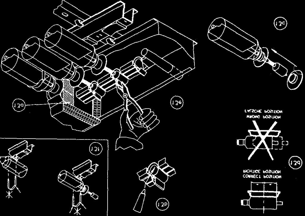
6 INSTALLATION PROCEDURE FOR MAZDON, SLOPING ROOF (M) SYSTEM See Fig Select a suitable position for the collector. It should face due south. Recommended angle of tilt is the same as your geographical latitude. Distances between perforated bands are given in mm. 2. Remove tiles. 3. Secure the LOWER band (Pt. No. B0290) to rafter using coach screws (Pt. No. A0168) and washers (A0170) 4. Replace tiles. 5. Locate and secure bottom end of side rail (Pt. No. B0282) to LOWER band. Use captive washer (Pt No. A0330) to hold the bolt of the lowest hole in place for later use. 6. Locate one support rail (Pt. No. B0177 or B0178) in tab on side rail (Pt. No. B0282), bolt both to UPPER band. Distance from side rails to ends of support rail should be equal. 7. Secure the UPPER band to rafter. 8. Locate the other support rail (Pt. No. B0177 or B0178) in tab on side rail (Pt. No. B0282), bolt both to LOWER band. Distance from side rails to ends of support rail should be equal. 9. Locate manifold (Pt. No. B0832 or B0833) in tab at top of side sails and bold as shown. The distance from the side rails to the ends of the manifold should be equal. 10. Ensure that both support rails and manifold are in line. Tighten all bolts. 11. Locate manifold fittings to manifold inlet and outlet. Note that the air vent should be installed vertically. Check all plumbing and pipework between collector and hot water storage tank. Fill system and then turn the circulating pump on. 12. Remove self-tapping screws and remove manifold lid Remove top layer of insulation from manifold - Apply heat transfer paste, thinly and evenly to the condenser location seats of the manifold chamber. - Unpack first tube, push one rubber disc gently over the condenser end of the tube with flange facing glass, and onto rubber grommet. Starting at one end of the manifold, insert condenser through hole in front of manifold and into manifold chamber, resting tube body on rubber of the support rails. Rubber disc should seal up against front of manifold. ENSURE SELECTIVE COATING SURFACE IS UPPERMOST - Make sure condenser sits evenly through hole in manifold chamber. - Using a pair of pliers, squeeze the retaining clip tightly together, making sure there are no air gaps. - Fit clips over tube to both support rails. Note: Push clips only where shown repeat for all tubes - Replace top layer of insulation into manifold. 14. Replace manifold lid and secure with self-tapping screws. 15. Switch pump control unit to automatic.
")


7 Sloping Roof (M) MAZDON Fig. 3 Fig. 4 Fig. 5. Fig. 6
8 Fig. 7 Sloping Roof (M) MAZDON Ground Points For Lightening Conduction
9 INSTALLATION PROCEDURE FOR MAZDON, SLOPING ROOF (K) SYSTEM See Fig Select a suitable position for the collector. It should face due south. Recommended angle of tilt is the same as your geographical latitude. Distances between perforated bands are given in mm. 2. Remove tiles. Secure the LOWER leg of UPPER bracket (Pt. No. B0249) to rafter replace tile between bracket legs. 3. Secure UPPER bracket of leg to rafter and replace remaining tiles. 4. Locate and secure LOWER bracket to bottom end of side rail (Pt. No. B0282) 5. Locate one support rail (Pt. No. B0177 or B0178) in tab on side rail (Pt. No. B0282), bolt both to UPPER bracket. 6. Secure lower leg of LOWER bracket to rafter. 7. Secure upper leg of bracket to rafter. Replace remaining tiles 8. Locate manifold (Pt. No. B0832 or B0833) in tab at top of side sails and bold as shown. The distance from the side rails to the ends of the manifold should be equal. 9. Locate support rail (Pt. No. B0177 or B0178) in tab on side rail (Pt. No. B0282), bolt both to LOWER bracket. 10. Ensure that both support rails and manifold are in line. Tighten all bolts. 11. Locate manifold fittings to manifold inlet and outlet. Note that the air vent should be installed vertically. Check all plumbing and pipework between collector and hot water storage tank. Fill system and then turn the circulating pump on. 12. Remove self-tapping screws and remove manifold lid Remove top layer of insulation from manifold - Apply heat transfer paste, thinly and evenly to the condenser location seats of the manifold chamber. - Unpack first tube, push one rubber disc gently over the condenser end of the tube with flange facing glass, and onto rubber grommet. Starting at one end of the manifold, insert condenser through hole in front of manifold and into manifold chamber, resting tube body on rubber of the support rails. Rubber disc should seal up against front of manifold. ENSURE SELECTIVE COATING SURFACE IS UPPERMOST - Make sure condenser sits evenly through hole in manifold chamber. - Using a pair of pliers, squeeze the retaining clip tightly together, making sure there are no air gaps. - Fit clips over tube to both support rails. Note: Push clips only where shown repeat for all tubes - Replace top layer of insulation into manifold. 14. Replace manifold lid and secure with self-tapping screws. 15. Switch pump control unit to automatic.
10 Sloping Roof (K) MAZDON

11 Fig. 12 Sloping Roof (K) Ground Points For Lightening Conduction
12 INSTALLATION PROCEDURE FOR MAZDON FLAT ROOF (F) SYSTEM See Fig Select a suitable position for the collector. It should face due south. Recommended angle of tilt is the same as your geographical latitude. Distances between perforated bands are given in mm. 2. Position and bolt front brackets (Pt. No. A0327) and rear brackets (Pt. No. A0328) to the flat roof or surface using coach screws (Pt. No. A0168). Use raw plugs (Pt. No. A0886) 3. Fix rear strut assembly (Pt. No. B0356) to rear bracket (Pt. No. A0328). 4. Bolt side rail (Pt. No. B0282) to front bracket (Pt. No. A0327) using bottom hole in side rail. 5. Locate one support rail (Pt. No. B0177 or B0178) in tab on side rail (Pt. No. B0282), bolt both to rear strut (Pt. No. B0356). Distance from side rails to ends of support rail should be equal. 6. Locate the other support rail (Pt. No. B0177 or B0178) in tab on side rail (Pt. No. B0282) bolt as shown. 7. Locate and secure side brace (Pt. No. B0005) using the single hole in the front bracket. Secure the other end using slots to rear in either position shown. Locate a second side brace to the other side of frame. 8. Locate the universal brace (Pt. No. B0006) diagonally between rear struts and cut off any excess length. 9. Locate manifold (Pt. No. B0832 or B0833) in tab at top of side rails and bolt as shown. The distance from the side rails to the ends of the manifold should be equal. 10. Ensure that both support rails and manifold are in line. Tighten all bolts. 11. Locate manifold fittings to manifold inlet and outlet. Note that the air vent should be installed vertically. Check all plumbing and pipework between collector and hot water storage tank. Fill system and then turn the circulating pump on. 12. Remove self-tapping screws and remove manifold lid Remove top layer of insulation from manifold - Apply heat transfer paste, thinly and evenly to the condenser location seats of the manifold chamber. - Unpack first tube, push one rubber disc gently over the condenser end of the tube with flange facing glass, and onto rubber grommet. Starting at one end of the manifold, insert condenser through hole in front of manifold and into manifold chamber, resting tube body on rubber of the support rails. Rubber disc should seal up against front of manifold. ENSURE SELECTIVE COATING SURFACE IS UPPERMOST - Make sure condenser sits evenly through hole in manifold chamber. - Using a pair of pliers, squeeze the retaining clip tightly together, making sure there are no air gaps. - Fit clips over tube to both support rails. Note: Push clips only where shown repeat for all tubes - Replace top layer of insulation into manifold. 14. Replace manifold lid and secure with self-tapping screws. 15. Switch pump control unit to automatic.
13 Flat Roof (F) Fig. 13 Fig (30-Tube) (ZO-Tube) Fig. 15 Fig. 16

14 Fig. 17 Flat Roof (F) MAZDON Ground Points for Lightening Conduction X = 12lOmm α = 40 X = 1094mm α = 38 X = 976mm α = 30 X = 862mm α = 25 X = 746mm α = 20 α X
15 MANIFOLD CONNECTIONS The manifold flow and return connections are 22mm in diameter and are designed for use with compression couplings. The recommended manifold connections for installations are given in Fig 18 below. For multiple manifold installations, the following is a recommended maximum number of manifolds that should be connected in series: 4 of 20 tube manifolds 3 of 30 tube manifolds Part Numbers Fig A Al l22 3. A A PIPEWORK AND PLUMBING For a solar installation with pipework of total length metres, the following dimensions are recommended for the flow and return pipework: System Tubing Dimensions 30 tubes 15mm by 1mm or l/2 NB 60/90 tubes 22mm by l mm or 3 /4 NB 120 tubes I28mm by l mm or 1 NB Installed within the flow and return circuits of the system should be (see Fig 19.): PUMP (7), with flow meter attached to monitor flow of water within the system. NON-RETURN VALVE (2), to prevent gravitational flow of water in flow circuit from the collector when the storage tank temperature may be greater than the collector temperature (i.e. at night). Be sure to install correctly. MANUAL and AUTOMATIC AIRVENTS (l) fitted to the highest part of the system to facilitate removal of air pockets from the system. Air vents should be open when filling the system. cont d
16 AN EXPANSION VESSEL (9), to contain increased water volume in the system due to rise in temperature and hence increased pressure of water. A combined PRESSURE RELIEF VALVE and PRESSURE GAUGE (11) to monitor the pressure of the system and to serve as a safety mechanism to avoid over pressuring of the system (e.g. 3 bar 45 psi.) DOUBLE CHECK VALVE (10),to stop back-syphonage of water into cold mains water supply. FILLING LOOP, consisting of a flexible hose and stop valve that connects from water mains supply to hose connector and filler valve. PIPES SHOULD ALWAYS BE INSTALLED RISING SLIGHTLY TO AVOID THE CREATION OF AIR POCKETS NOTE THAT WHEN INSTALLING THE COLLECTOR AND PIPEWORK IT IS IMPORTANT THAT ALL LOCAL AUTHORITY REGULATIONS AND RELEVANT STANDARDS ARE ADHERED TO. WHEN FILLING THE SYSTEM ALL VALVES SHOULD BE OPEN i.e. PUMP BALL VALVES, CHECK VALVES ETC. 1a 1b Fig. 19 Fig. 20 1a Manual Air Vent 6 Coil (Solar System) 1 Electric Element (immersion heater) 1b Automatic Air Vent 7 Pump 2 Non Return Valve 8 Flow Meter 3 Storage Tank 9 Expansion Vessel 4 Coil Central Heating) 10 Filling Loop 5 Drain 11 Pressure Relief Valve
17 EXPANSION VESSEL (see Fig. 21 next page) If the water temperature in the system rises, water volume will increase resulting in a rise in pressure and the possibility of damage to the system if the expansion is not absorbed. By incorporating an expansion vessel into the system, the increase in water volume may be contained until the water temperature has reduced and the water volume returns to its initial level. The vessel consists of two halves. One half connects directly to the water system. The second, separated by a special diaphragm, contains nitrogen or air. As pressure rises and volume increases, the diaphragm is displaced. The size of the expansion vessel required depends on the volume of water in the solar collector circuit, maximum working temperature, maximum working pressure and the vessel pre-charge pressure. The size can be calculated as follows: First calculate the required expansion volume. Vu = Required expansion volume of vessel Vi = Volume of water in the solar collector circuit a = Expansion of water at the maximum working temperature, as a percentage of its volume at 0 C a = 3.2% at 90 C, 6.0% at 120 C, 9.0% at 150 C. Vu = Vi x a (1) 100 Next calculate the expansion efficiency of the vessel. c = Expansion efficiency Pw = Maximum working pressure, typically 3.5 bar (52.5 psi) Pi = Initial system pressure (expansion vessel pre-charge pressure), typically 1.5 bar (22.5 psi). c = Pw-Pi Pw +1 (2) Finally calculate the total volume, Vv, of the expansion vessel. Vv = Vu c Example: Find the required capacity of a vessel for a system pre-charged to 1.5 bar (22.5 psi), solar collector circuit volume 80 litres, max temperature 90 C and maximum working pressure 3.5 bar (52.5 psi) Equation (1) gives (3) Vu = 80 x 3.2 = 2.56 litres 100 (2) gives c = = (3) gives Vv = 2.56 = 5.8 litres 0.44 Therefore select an expansion vessel of at least 6.0 litres.
18 Fig. 21 EXPANSION VESSEL Connection to System
19 SERIES TANK INSTALLATION MAZDON For large installations two or more tanks may be connected to the solar system in series (preheat).fig 22, Fig 23. Fig Storage Tank 2. Reheat Fig way valve (short circuit) 2. 3 way valve (preheat 1) 3. 3 way valve (preheat 2) 4. Storage Tank 5. Preheat 1 6. Preheat 2 Applications: Hotels, Hospitals, Multi-storey Buildings
20 PARALLEL TANK INSTALLATIONS MAZDON A number of storage tanks may be connected in parallel to the collector system. Applications: Hotels, Hospitals, Multi-storey buildings When the water temperature in Tank 1 reaches a set temperature, the water from the collector is directed via a motorized 3-way valve, controlled by a temperature sensor at Tank 1, to Tank 2. If the temperature in Tank 1 falls below set temperature, the water from the collector is redirected through its heating coil. See Fig 24. Fig Motorized 3-way switch 2. Tank 1 3. Tank 2 4. Tank 3
21 CALCULATING PUMP SIZE When sizing a pump it is often necessary to calculate the system flow rate and the system pressure drop. Water Flow Rate: The recommended water flow rates are in the range of 0.1 to 0.25 litres/min per collector tube. Increased flow rates will not increase system performance; they will however increase the system pressure drop. Example: If we select a flow rate of 0.1 l/min per collector tube then: Flow rate in each branch is 90 tubes x 0.1 l/min/tube = 9 l/min. System flow rate is 180 tubes x 0.1 l/min/tube = 18 l/min. Fig tube 30 tube 30 tube 30 tube 30 tube 30 tube Pressure Drop As explained above, if manifolds are connected in series a higher flow rate is necessary. Since pressure drop increases with a higher flow, the pressure drop in each manifold will increase also. The graph below gives the approximate pressure drop for a single manifold at various flow rates: Fig. 26 Pressure drop for single manifold. Pressure Drop in kpascals Flow litres/min
22 Specific Flow Rate [litre/min/tube] MAZDON PRESSURE DROP OF MAZ30 UNDER VARIOUS FLOW RATES (Approximate guideline only) Number of s in series Total flow rate [litre/min] Total pressure drop of 4 Maz30 manifolds [kpa] Specific Flow Rate [litre/min/tube] Number of s in series Total flow rate [litre/min] Total pressure drop of 3 Maz30 manifolds [kpa] Specific Flow Rate [litre/min/tube] Number of s in series Total flow rate [litre/min] Total pressure drop of 2 Maz30 manifolds [kpa] Series Installations: To obtain a pressure drop through manifolds connected in series add the pressure drops for each manifold. Ps = Pm1 + Pm2 + etc. Ps = Pressure drop across system Pm1 = Pressure drop across manifold 1 (from graph) Pm2 = Pressure drop across manifold 2 (from graph) Fig. 27
23 Parallel Installations For larger installations where manifolds are connected in parallel, the system pressure drop is equal to the pressure drop in a single branch, as calculated above, irrespective of the number of branches. Fig. 28 Flow Rate And Pressure Drop Examples Examples below are manifold and connection pressure drops, pipework losses are not included. Example 1: Three manifolds in series Fig tube 30 tube 20 tube Typical flow rate = 80 tubes x 0.1 1/min/tube = 8/1min From Graph: pressure drop at 8 1/min for 30 tube manifold = 4.8 kpa pressure drop at 8 1/min for 20 tube manifold = 3.2 kpa Therefore total pressure drop = = 12.8 kpa Example 2: next page
24 Example 2: Previous (Fig. 29) example in parallel Fig tube 30 tube 20 tube 30 tube 30 tube 20 tube Typical branch flow rate = 80 tubes x 0.1 1/min/tube = 8 1/min Typical system flow rate = 160 tubes x 0.1 1/min/tube = 16 1/min Branch pressure drop (as example 1) = 12.8 kpa System pressure drop = branch pressure drop = 12.8 kpa CALCIUM DEPOSIT AND AGGRESSIVE WATER In areas where local water is known to be hard or aggressive, a heat exchanger MUST be used and the use of water softener is recommended, otherwise regular cleaning of the system will be required. IN ANY CASE A HEAT EXCHANGER IS STRONGLY RECOMMENDED. Chloride Ion Presence In areas where chloride ion concentration is greater than 40 ppm a heat exchanger MUST be used in hot water storage tank. The solar system should be filled with distilled or de-chlorinated water.
25 Collector Efficiency and Sizing MAZDON Fig. 31 Figure 31 (at left) gives details of collector efficiency for various insolation levels, installations and ambient temperatures. Figure 32 (below left) shows the measured efficiency curve of the collector system vs. solar insolation. Information on the sizing of a system can be obtained from the chart given in Figure 33 and by following steps 1 through 11 below. Fig. 32 Step 1 Determine the number of people using solar water heating system. Step 2 Using local data, find hot water consumption per day, per person. (ASHRAE recommends 20 gallons per day, per person.) Step 3 Select the Solar Water Heater tank size. Step 4 Find solar insolation and hours of sunshine per year. Step 5 Select the solar collector installation location. Step 6 Calculate deviation from true North/South line. Step 7 Find local latitude Step 8 Find roof angle or installation tilt angle. Step 9 Calculate the difference between local latitude and roof angle. Step 10 Estimate Thermomax tubes required. Step 11 Contact your local dealer for delivery and pricing information
26 Fig. 33 MAZDON A: Consumption = Litres of Hot (50 C) Water Per Day Per Person B: Insolation = Hours of Sunshine Per Year C: Orientation = Deviation from North/South Line (Shown as 0 ) D: Inclination = Difference Between Local Latitude And Roof Angle Example: 5 people with a requirement of 50 litres per day, per person, with a local Annual Insolation of 1400 hours. Orientation of the roof is 30 West of South. The local latitude is 45 and the roof angle is 35 (inclination difference 10 ). This, as can be seen from the plotted line on the chart, indicates a requirement for 45 tubes with a storage capacity of 375 litres.
27 Domestic and Commercial Energy Requirements MAZDON Tables given on the following pages give a brief guide to some domestic and commercial energy requirements for hot water and space heating. PLEASE NOTE THAT THESE SHOULD ONLY BE USED AS A VERY ROUGH GUIDE. Table 1) Table 2) Table 3) Table 4) Table 5) Table 6) Table 7) Table 8) Average Domestic Hot Water Utilization Hotel/Restaurant/Guest House Outdoor Pool Energy Requirement Outdoor Pool Specific Heat Loss Average Space Heating Requirements Typical Requirements for a Middle European House Latent Heat System Sizing Table 1 AVERAGE DOMESTIC HOT WATER UTILIZATION PER HOUSEHOLD APPLICATIONS Sink Wash Basin Bath Shower Bidet Washing m cold Washing m hot Total Consumption Low Average High APPLICATIONS Table 2 WATER TEMP. C CONSUMPTION lit/day HOTEL/RESTAURANT/GUEST HOUSE WATER TEMP. C CONSUMPTION lit/day Restaurant per menu per guest Hotel per room Room + wash basin Room + shower Room + bath Guest house NOTE: ALL ABOVE DATA VARIES ACCORDING TO METHODS OF INSULATION, AGE AND SIZE OF DWELLING, EXTERNAL AND TARGET TEMPERATURES.
28 Table 3. OUTDOOR POOL ENERGY REQUIREMENTS (kwh) MAZDON WATER TEMP C SWIMMING SEASON/YEAR 4 mths 5 mths 6 mths UNITS KWh/m 2 season Example: Energy requirement to heat pool for 4-month season to 22 C Assume solar insolation of 5 KWh/m 2 /day 4 month season = 120 days Therefore: 5 kwh x 120 days = 600 kwh/m 2 /season Collector efficiency = 0.7 Therefore: 600/0.7 = 420 kwh/m 2 /season, energy available during a 4 month period from collector. Energy required to heat pool to 22 C from Table 3 is 150 kwh/m 2 /season 150/450 = 1/3 i.e.: require a ratio of collector surface area to pool surface area of 1:3 Target Temp C Table 4 SPECIFIC HEAT LOSS (kwh) FOR OUTDOOR POOL Swimming Period in Months/Annum Pool A Pool B Pool C Pool D Units: kwh/ m 2 Pool A : Pool with two sides well-protected (trees, building or wall) wind speed 1 m/s. Pool B : Pool with two sides partially protected wind speed 2 m/s. Pool C : Pool with no protection, wind speed 4 m/s. Pool D : Pool with a cover of coefficient of conductivity of 8.12 W/m K. NOTE: ALL ABOVE DATA VARIES ACCORDING TO METHODS OF INSULATION, AGE AND SIZE OF POOL, EXTERNAL AND TARGET TEMPERATURES.
29 Table 5 AVERAGE SPACE HEATING REQUIREMENTS TARGET TEMP 20 C BUILDING TYPE Small detached Large detached Bungalow Large semi Small semi Semi bungalow Terrace End terrace FLOOR SPACE sq m Loft only INSULATION Loft & Walls UNITS kwh/ m 2 /annum Example: Energy requirement to heat large detached house, floor space 150m 2 Assume solar insolation of 3 kwh/ m 2 /day Therefore: 3 kwh x 180 days = 540 kwh/ m 2 /annum Energy required to heat a large detached house with good loft and wall insulation, floor space 150 m 2, to a target temperature of 20 C, is 110 kwh/ m 2 /annum. 110/378 = approx 0.3. i.e. require a ratio of collector area to floor space of 30%, giving a collector area of 50 m 2 House type Table 6 Terrace TYPICAL REQUIREMENTS FOR A MIDDLE EUROPEAN LOCATION Corner terrace house Detached house Small apartment Block (2x) Apartments (4x) Apartments (8x) Apartments (16x) A B C D E F G H Solar heat exchanger: approx. 0.3 m 2 /10 tubes Specifications: A. Approximate storage capacity m 2 B. Number of people C. Approximate hot water requirement in litres/day D. Hot water losses in litres/day Flow Rate: approx /h per 10 tubes E. Hot water production in litres/day F. Heat output new building (kw) G. Heat output old building good H. Heat output old building bad
30 Latent Heat Table 7 1 m 2 of collector area, with insolation of 1000 W/m 2 can approximately in one hour: i) increase temperature of 7.8kg of water from 25 C to 100 C or ii) produce 1 kg of vapour at 100 C from water at 100 C or iii) produce 0.9 kg of vapour at 100 C form water at 25 C or iv) produce 0.8 kg of vapour at 140 C from water at 25 C System Sizing Table 8 Number of persons Number of tubes Application tank size in litres PLEASE NOTE THAT THESE SHOULD ONLY BE USED AS A VERY ROUGH GUIDE.
31 Periodic Checks 1. Ensure that no physical damage has occurred to the tubes and remove any debris that may have accumulated. 2. Check the flow and return pipework between the collector and the storage tank. Check all connections for leaks and ensure that all components are operating correctly. 3. Check that the system pressure is maintained at 15 psi. If the pressure continually drops below 5psi then check the system for leaks. Five Yearly Checks 1. Every five years the Antifreeze in the collector loop should be checked. Good quality antifreezes like DowFrost HD can last up to 20 years. If necessary the system should be completely drained and flushed then refilled with new antifreeze. 2. Check the pipework insulation for deterioration. 3. Check the seals where the flow and return connections pass through the roof. Pressure Loss Periodically check the pressure gauge. If pressure loss in the system is apparent it may be due to one of the following: 1. Faulty pressure relief valve. - If pressure setting is wrong - correct it. If the relief valve fails to operate, drain the system and replace the valve. 2. Leakage. - If water is escaping from the system the volume of water in the system, and therefore the system pressure will decrease. Check all pipework and plumbing for the possibility of leads. If they do occur, drain the system and repair. 3. Overheating. - Overheating may occur if the pump isn t operating during a period of sunshine and water is not being circulated (i.e. power cut). Thermal energy is not being removed from the collector so the water temperature will rise, hence the water volume and the system pressure will increase. This can result in the release of steam or hot water from the air vent or pressure relief valve. When the system returns to normal operating conditions the system pressure will be reduced due to the loss of water. Top up the system to a pressure of 15 psi. Replacement of Tubes Due to the Thermal diode operation of the collector tube, damaged or broken tubes do not negatively affect the operation of the system, but merely reduce the efficiency of that tube. It is possible, therefore, to delay replacement of tubes to a suitable time. Pumps and Controls Thermomax Collectors can be installed with a variety of different pumps and controllers. The logic behind different makes of controller varies greatly. If you have a controller problem refer to the manual that came with the controller. If unable to solve it contact the installer or Thermomax at the address below. Thank you for purchasing a THERMOMAX collector. We know you will enjoy years of hot water from your system!
32 PARTS LIST C0132 SMT100 C0126 SMT300 C0128 SMT 400 C0031 MAZDON 20M MANIFOLD C0034 MAZDON 30M MANIFOLD C0045 TMA 400 TUBES (10 X) C0213 TMA 600 S (10 X) MAZDON B0005 ELEVATION KIT BRACE B0006 UNIVERSAL BRACE B0007 REAR STRUT (F) A0168 REAR BRACKET (F) A0167 FRONT BRACKET A0174 HINGE ASSEMBLY FOR REAR BRACKET B0177 BOTTOM SUPPORT RAIL (20) B0178 BOTTOM SUPPORT RAIL (30) B0282 SIDE RAIL B0249 ROOF BRACKET (K) B0290 ROOF BRACKET (M) A0064 SUPPORT CLIPS (type 1) A0087 RUBBER WASHERS A0169 HEX NUTS S/S A0170 M8 PLAIN WASHERS A0172 M8 SPRING WASHERS A0173 FORMED WASHER A0175 M8 X 20 BOLT A0176 CLAMPING PLATE WASHER A0330 FIBRE WASHER A mm LONG HINGE TUBING A0759 TOP SUPPORT RAIL CONNECTING SET A0921 SUPPORT CLIPS (type 2) COMPRESSION FITTINGS A0188 A0332 A0351 A0477 A0683 A0740 A0741 A0742 A1121 A1122 A1123 A1196 A mm x ½ BSP (F) x 22mm T PIECE TANK SENSOR POCKET COACH SCREW KIT COLLECTOR SENSOR POCKET RETURN SENSOR POCKET RETURN SENSOR COLLECTOR SENSOR TANK SENSOR ½ BSP PLUG MANUAL AIR VENT (½ BSP) COUPLING SET (2 x tees, manual air vent, connecting tube, plug) AUTOMATIC AIR VENT (½ BSP) 22mm x 56mm CONNECTION TUBE
HCA-58/20(30) SOLAR COLLECTOR INSTALLATION MANUAL
 SOLAR COLLECTOR INSTALLATION MANUAL") HCA-58/20(30) SOLAR COLLECTOR INSTALLATION MANUAL Copyright:Changzhou He Jia Solar Energy Co.,Ltd www.hjsolar.com.cn - 0 - 1. CAUTIONS 1.1 Gloves and Eye protection must be used when handling glass tubes.
HCA-58/20(30) SOLAR COLLECTOR INSTALLATION MANUAL Copyright:Changzhou He Jia Solar Energy Co.,Ltd www.hjsolar.com.cn - 0 - 1. CAUTIONS 1.1 Gloves and Eye protection must be used when handling glass tubes.
For our present, For their future. Version 11.03
 For our present, For their future. SFB-AL (SF-B) series Installation Manual All-glass Evacuated Tubular Solar Collector with Heat Pipe Contents http://www.sunflower-solar.com/ 1. SOLAR COLLECTOR SIZE AND
Version For our present, For their future.
 For our present, For their future. 1 SFB-AL (SF-B) series Installation Manual All-glass Evacuated Tubular Solar Collector with Heat Pipe Contents 1. Solar collector size and weight:... 3 2. How to transport
Revision THERMO TECHNOLOGIES. USDT 2001 Differential Controller. Installation and User s Guide
 Revision 8 THERMO TECHNOLOGIES USDT 2001 Differential Controller Installation and User s Guide USDT 2001 DIFFERENTIAL CONTROLLER Installation and User s Guide Table of Contents Introduction General Information
SPLIT SOLAR HEATER SWSP-200 SWSP-300
 READ THIS GUIDE BEFORE STARTING SYSTEM INSTALLATION SPLIT SOLAR HEATER SWSP-200 SWSP-300 INSTALLATION AND OPERATION MANUAL V032018-1 CONTENT 1. Important Information... 3 2. Unpack and Inspect... 5 3.
Fact Sheet Sky CPC 58
 Principle: The CPC 58 solar vacuum tube collector is composed of a series of borosilicate glass pipes with double air gap, welded at the end, inside which a vacuum is closed. The internal air gap is made
Detailed Assembly Instructions. ATS Evacuated Tube - Solar Panel Units ATS10 / ATS20 / ATS30
 Detailed Assembly Instructions ATS Evacuated Tube - Solar Panel Units ATS10 / ATS20 / ATS30 Release: 2/2012 1 ATS-10, ATS-20, and ATS-30 tube collectors are all setup using a similar method. Carefully
Installation and Operation Manual for a Solar System with KPW Collectors
 Installation and Operation Manual for a Solar System with KPW Collectors EN v. 1.0 CONTENTS General Installation and Operation Instructions... 3 Collector Technical Data....... 4 1 Delivery of Mounting
Solar Thermal. Grant Solar Pump Station Installation & Servicing Instructions
 Solar Thermal Grant Solar Pump Station Installation & Servicing Instructions Part No. DOC 96. Rev 02. October 2012 Important Note Important Note for Installers The Pump Station supplied with your Grant
OPERATION AND INSTALLATION
 OPERATION AND INSTALLATION RESIDENTIAL SOLAR PUMP STATION» SE FLOWSTAR PUMP STATION Table of Contents 1 For your safety 1.1 About this manual 1.2 Designated use 1.3 Qualification of the installer 1.4 Hand-over
GUIDE FOR CHOOSING AN ACCUMULATOR TANK
 GUIDE FOR CHOOSING AN ACCUMULATOR TANK Preliminary version 0.1 13.3.2006 TABLE OF CONTENTS 1 OVERVIEW.. 5 2 OPERATING PRINCIPLE.. 6 3 DIMENSIONS. 8 4 PRODUCT RANGE. 10 5 SPATIAL REQUIREMENTS.. 12 6 TECHNICAL
Installation and Operation Manual for a Solar System with KPC1-BP Collectors
 Installation and Operation Manual for a Solar System with KPC1-BP Collectors EN v. 1.3 CONTENTS General Installation and Operation Instructions... 3 Collector Technical Data....... 4 1 Delivery of Mounting
Geo-Prime Tank. Table of Contents. Installation, Operation & Maintenance Instructions AFCG1PT Revision: 7/3/14. Replacing a Pump 12
 Geo-Prime Tank Installation, Operation & Maintenance Instructions AFCG1PT Revision: 7/3/14 Table of Contents General Description 3 Installation 4 Flushing and Purging 7 Initial Start-up 9 Replacing a Pump
Example printout. Building project. SDC Example. Dyfi Eco Park SY20 8AX Machynlleth UK. Mr C. Laughton Phone:
 Building project SDC Example Dyfi Eco Park SY20 8AX Machynlleth UK Contact person: Mr C. Laughton Phone: 01654 700324 E-Mail: software@solardesign.co.uk Results of annual simulation Installed collector
SOLAR WORLD, INC. INSTALLATION MANUAL
 SOLAR WORLD, INC. INSTALLATION MANUAL Read this manual before beginning installation of solar system INSIDE THIS MANUAL Section 1 illustrates the kits and components used for installation of the solar
FLEXIBLE PHOTOVOLTAIC MODULES. Instruction Manual
 FLEXIBLE PHOTOVOLTAIC MODULES Instruction Manual 1 THE PHOTOVOLTAIC MODULE Introduction A photovoltaic module is a device that converts solar energy into electrical energy, thanks to the presence of silicon
Installation & Technical Guide. Domestic & Commercial.
 Installation & Technical Guide Domestic & Commercial www.challisbooster.com www.challisboosterplus.com Installation and Technical Guide Domestic and Commercial Challis Water Controls Europower House, Lower
W91/W94 Series TEMPERATURE REGULATORS. Self-Operated Temperature Regulators. Design & Operation W91 Non-Indicating W94 Dial Thermometer
 Design & Operation W91 Non-Indicating W94 Dial Thermometer Watson McDaniel reserves the right to change the designs and/or materials of its products without notice. 2010 Watson McDaniel Company CAPILLARY
EJECTORS GENERAL OPERATION & MAINTENANCE MANUAL
 EJECTORS GENERAL OPERATION & MAINTENANCE MANUAL The information contained in this manual was current at the time of printing. The most current versions of all Hydro Instruments manuals can be found on
AP Solar Collector Installation and Operation Manual. International Edition Rev. 1.5 (Sept 2005)
") AP Solar Collector Installation and Operation Manual International Edition Rev. 1.5 (Sept 2005) Introduction Thank you for purchasing an Apricus AP solar collector. This unit is designed to provide years
AP Solar Collector Installation and Operation Manual International Edition Rev. 1.5 (Sept 2005) Introduction Thank you for purchasing an Apricus AP solar collector. This unit is designed to provide years
VIESMANN. Installation instructions VITOSOL 200-T. for contractors. Vitosol 200-T Type SP2 Vacuum tube collector based on the heat pipe principle
 Installation instructions for contractors VIESMANN Vitosol 200-T Type SP2 Vacuum tube collector based on the heat pipe principle VITOSOL 200-T 6/2010 Dispose after installation. Safety instructions Please
INSTALLATION MANUAL. IEC version. TSM_IEC_IM_2012_RevB
 INSTALLATION MANUAL The Solution in Black The Comax Solution The Quadmax Solution The Universal Solution The Aesthetic Solution The Utility Solution The Honey Module IEC version TSM_IEC_IM_2012_RevB Table
Installation manual. Cooling system. Industrial engines DC09, DC13, DC16 OC16. 01:05 Issue 12 en-gb. Scania CV AB 2018, Sweden
 Installation manual Cooling system Industrial engines DC0, DC13, DC OC 333 3 01:05 Issue en-gb Changes from the previous issue...3 Design and dimensioning...3 Expansion tank...4 and earlier emission levels...
Technical Product Submittal
 1. General Specifications 1.01 Certifications 1) SRCC OG-100 Technical Product Submittal Oventrop evacuated tube solar thermal collector OVSOL 5-8, 8 tube collector and OVSOL 5-16, 16 tube collector SRCC
INSTALLATION AND COMMISSIONING MANUAL CONTENTS. Function. Important Product range Technical specifications
 28237 www.caleffi.com Circulation units for solar thermal systems Copyright 204 Caleffi 278-279 series INSTALLATION AND COMMISSIONING MANUAL CONTENTS Function Important Product range Technical specifications
To ensure proper installation, digital pictures with contact information to before startup.
 Check List for Optimal Filter Performance? There should be no back-pressure on the flush line. A 1 valve should have a 2 waste line, and 2 valve should have a 3 waste line. Do not use rubber hosing or
Non-Imaging Concentrator based Solar System Operations & Maintenance Manual
 Non-Imaging Concentrator based Solar System Operations & Maintenance Manual UNDP-GEF Project on Concentrated Solar Heat Ministry of New & Renewable Energy Government of India November, 2014 Prepared By:
 Generator, Unit Hydrogen, Seal Oil, Stator Coolant, Demin Water Plant Operations Training Huntly Power Station: Units 1-4 Assessment ID: 8014, 8012, 8009, 8015, 8016 NZQA Unit Standard: 17413 Assessment
Nanometrics Solar Power System
 Nanometrics Solar Power System Installation Guide Nanometrics Inc. Kanata, Ontario Canada 2003 Nanometrics Inc. All Rights Reserved. Installation Guide The information in this document has been carefully
SDHW System Inspection Form
 SDHW System Inspection Form Project/Homeowner Name: Project #: Date: Contractor: Inspector: In Attendance: Approx Install Date: Type of System Closed Loop Drain Back Drain Down Thermosyphon Other Type
DS Series Solar System
 DS Series Solar System Permit information Consol 30-58-1800 Collector Flat mount on Colorsteel Plumdeck roofing Valve vent, Open loop http:// www.consolsolar.co.nz 21 Page 1 of This system is an evacuated
40% Solar thermal, cooling and electricity LET THE SUN LOWER YOUR DAILY OPERATIONAL COSTS AND LET YOUR GUESTS ENJOY A GREEN AND COMFORTABLE STAY OVER
 Solar thermal, cooling and electricity OVER 0% SAVINGS LET THE SUN LOWER YOUR DAILY OPERATIONAL COSTS AND LET YOUR GUESTS ENJOY A GREEN AND COMFORTABLE STAY THE SOLARUS POWERCOLLECTOR TM THE NEW POWER
MODEL NUMBER: MEDIUM DUTY ONBOARD AIR SYSTEM
 MODEL NUMBER: 10003 MEDIUM DUTY ONBOARD AIR SYSTEM IMPORTANT: It is essential that you and any other operator of this product read and understand the contents of this manual before installing and using
INSTALLATION & OPERATION MANUAL
 Model # SQ-1220 INSTALLATION & OPERATION MANUAL Read all the instructions before installing your solar heating system. How does a solar heating system work? 1. Connect your existing pool pump to the solar
INSTALLATION AND COMMISSIONING MANUAL CONTENTS. Function. Product range. Technical specifications. Characteristic components
 7EN www.caleffi.com Circulation units for solar thermal systems Copyright Caleffi 7HE - 79HE series INSTALLATION AND COMMISSIONING MANUAL CONTENTS Function Product range Technical specifications Characteristic
VIESMANN. Installation instructions VITOSOL 300-T. for contractors. Vitosol 300-T Type SP3A Vacuum tube collector based on the heat pipe principle
 Installation instructions for contractors VIESMANN Vitosol 300-T Type SP3A Vacuum tube collector based on the heat pipe principle VITOSOL 300-T 9/2009 Dispose after installation. Safety instructions Please
Maximum output power with circulator Wo 6 kw. Maximum output power without circulator Wo 5 kw
 Packaged, metal-ceramic, water cooled continuouswave magnetron with integral RF cathode filter intended for use in industrial microwave heating applications. The tube features a quick- heating cathode,
Powertech/Apricus TM AP Solar Collector Specifications
 Powertech/Apricus TM AP Solar Collector Specifications Via a Powertech Thermal Store, this new home in Salisbury also uses the 88 tube solar energy array (two on the east side) to heat the pool once the
Geo-Prime Tank U.S. Patent Number 8,544,282
 www.geo-flo.com Geothermal and Hydronics Specialists Installation, Operating, and Maintenance Manual Part # 3487 Rev. 03JUL2014 Geo-Prime Tank U.S. Patent Number 8,544,282 Geo-Flo Products Corporation
Ministry of New and Renewable Energy Block-14, CGO Complex, Lodhi Road, New Delhi ,
 MNRE STD 01:2013 MNRE Standard ALL GLASS (GLASS IN GLASS) EVACUATED SOLAR COLLECTOR TUBES Ministry of New and Renewable Energy Block-14, CGO Complex, Lodhi Road, New Delhi-110 003, May 2013 1 MNRE STD
Gauges, Sight Glasses and Vacuum Breakers
 Gauges, Sight Glasses and Vacuum Breakers Gauges, Sight Glasses and Vacuum Breakers Gauges Pressure gauges Pressure gauges should be installed in at least the following situations: Upstream of a pressure
Solar Power Owner s Manual
 Solar Power Owner s Manual Domestic Photovoltaic Systems Introduction Congratulations on the purchase of your solar electricity system. Not only are you protecting yourself from current and future price
Title Goes Here and Can Run Solar Photovoltaic up to 3 lines as shown here Systems as you see
 Title Goes Here and Can Run Solar Photovoltaic up to 3 lines as shown here Systems as you see CHAPTER 2 Outline the components of a solar photovoltaic system Describe the operation of a solar photovoltaic
Secondary Coolant 301
 Secondary Coolant 301 Instructor Rusty Walker Hill PHOENIX Learning Center Secondary Coolant 301 Start-Up Procedures Secondary Coolant 301 Objectives Describe the initial startup procedures for a medium
SolarSheat Wall Installation Manual
 SolarSheat Wall Installation Manual Version 1.5 April 23, 2013 Copyright 2013 Your Solar Home, All Rights Reserved SolarSheat products must be installed in accordance to all local building, plumbing, electrical,
GASOKOL vacutube. GASOKOL GmbH, vacutube_de 1 von 5
 Principle: Because of the warming up the fluid into the absorber pipe converts into steam, the vacuum into the circuit supports this process. The steam rises by its own incentive. The fluid liquefies into
Revision. THERMO TECHNOLOGIES USDT 2004 Differential Controller. Installation and User s Guide
 Revision 3 THERMO TECHNOLOGIES USDT 2004 Differential Controller Installation and User s Guide USDT 2004 DIFFERENTIAL CONTROLLER Installation and User s Guide Table of Contents Introduction General Information
Results of annual simulation
 2 x Vitosol 100-FM SVKF Total gross surface area:4,46 m² Azimuth: 0 Incl.: 30 160 Liters/Day 50 C Gas-fired boiler 26 kw Vitocell 100-B Vol : 250 l Results of annual simulation Installed collector power:
Installation Instructions. Vitosol 100. Vitosol 100 Type w 2.5 Flat collector for flat roofs and freestanding installation Part No.
 Installation Instructions Vitosol 100 Type w 2.5 Flat collector for flat roofs and freestanding installation Part No. 3001 970 Vitosol 100 8/99 Safety instructions This hazard symbol precedes all important
WARNING Carefully Read These Instructions Before Use
 DO NOT RETURN THIS SPRAYER TO STORE Call: 1-800-950-4458 Backpack Sprayer Use and Care Manual Manufactured for Northern Tool + Equipment Co., Inc. WARNING Carefully Read These Instructions Before Use Model
Startup and Operation of SEE-THRU Nuclear Power Plant for Student Performance MP-SEE-THRU-01 Rev. 018
 Student Operating Procedure Millstone Station Startup and Operation of SEE-THRU Nuclear Power Plant for Student Performance Approval Date: 01/12/2011 Effective Date: 01/12/2011 TABLE OF CONTENTS 1. PURPOSE...3
MEDIUM POWER TRANSFORMER
 MEDIUM POWER TRANSFORMER MEDIUM POWER TRANSFORMER FROM 3,15 TO 31,5 MVA HIGHEST VOLTAGE FOR MATERIAL 72,5kV GENERAL CHARACTERISTICS Three phase oil-immersed naturally cooled type ONAN medium power transformers.
Operations and Assembly Manual
 Operations and Assembly Manual Betriebs- und Montageanleitung Assembly-Ready Montagefertige Solar Solarabsorber Absorber Solar Units Solar Units Solar Units Ice Rinks Ice Rink Rental Congratulations on
ENGINE COOLING Click on the applicable bookmark to selected the required model year
 ENGINE COOLING - ENGINE COOLING General Information/ Service Specifications/Lubricant/Sealants GENERAL INFORMATION 0000 The cooling system is designed to keep every part of the engine at appropriate temperature
Installation instructions
 Installation instructions Solar Collector 60965.0-.SD SKN.0 Series Flat Collector ON ROOF MOUNTING Solar Thermal Systems For heating engineers Please read carefully prior to commissioning and maintenance
Solar Thermal Energy Flat & Tube Panel Standard Kits Installation Overview
 Solar Thermal Energy Flat & Tube Panel Standard Kits Installation Overview Viessmann As a world leader in heating technology, Viessmann has 30 years experience in renewable energy systems and there are
ECONOPLATE BV SERIES HOT WATER SERVICE PACKAGED HEAT EXCHANGERS WITH THERMAL STORES
 ECONOPLATE BV SERIES HOT WATER SERVICE PACKAGED HEAT EXCHANGERS WITH THERMAL STORES TECHNICAL AND INSTALLATION DOCUMENTATION STOKVIS ENERGY SYSTEMS UNIT 34 CENTRAL PARK ESTATE 34 CENTRAL PARK ESTATE WEST
A/C-HEATER SYSTEM - AUTOMATIC
 A/C-HEATER SYSTEM - AUTOMATIC 1988 Toyota Celica 1988 Automatic A/C-Heater Systems Celica * PLEASE READ THIS FIRST * CAUTION: When discharging air conditioning system, use only approved refrigerant recovery/recycling
SSV2BR INSTRUCTIONS INSTALLATION INSTRUCTIONS
 SSV2BR INSTRUCTIONS INSTALLATION INSTRUCTIONS CONTROLLER MOUNTING: Find a suitable location to mount the control box. Ideally, as with all pool equipment it should be installed out of direct weather and
X5 / X6 N63 Upgrade Intercooler Installation Instructions
 X5 / X6 N63 Upgrade Intercooler Installation Instructions Part Number: D330-0016 Applications: 2010-12 E70 X5 xdrive 50i 2008-12 E71 X6 xdrive 50i PARTS LIST Qty Part No. Description 2 11 78 7 549 563
SE RV I CE MANUAL. Page 1 of 13
 SE RV I CE MANUAL Technical Data Mechanical Repair Electrical Repairs Calibration Fault Diagnosis Tools and Test Equipment Parts List Page 1 of 13 Technical Data Continuous operation, with intermittent
D/G-10 Maintenance. Daily. Shutdown Procedure During Freezing Temperatures. Periodically
 D/G-10 Maintenance NOTE: The numbers in parentheses are the Reference Numbers on the exploded view illustrations found in this manual and in the Parts Manual. Daily Check oil level and condition of oil.
INSTRUCTION MANUAL OIL SEALED ROTARY VACUUM PUMP MODEL PKS-016 PKS-030 PKS-070
 INSTRUCTION MANUAL OIL SEALED ROTARY VACUUM PUMP MODEL PKS-016 PKS-030 PKS-070 Components division ULVAC, Inc. Table of Contents 1. Inspection 4 2. Mounting 5 3. Oil filling 5 4. Electrical connections
2015+ SUBARU STI FRONT-MOUNT INTERCOOLER PARTS LIST AND INSTALLATION GUIDE INSTALL DIFFICULTY DISCLAIMER CAUTION INSTALL PROCEDURE TOOLS NEEDED
 PARTS LIST AND PARTS INCLUDED 1PC ALUMINUM INTAKE PIPE 1PC BAR-AND-PLATE INTERCOOLER 1PC STEEL CRASH BAR W/ MOUNTING HARDWARE 2PC HOT-SIDE INTERCOOLER PIPES 2PC COLD-SIDE INTERCOOLER PIPES 1PC BPV FLANGE
Product Catalog Evacuated tube collectors CPC OEM CPC w OEM
 Product Catalog 2004 Evacuated tube collectors CPC OEM CPC w OEM Table of Contents Development/design Production Outgoing goods warehouse Table of Contents Page Evacuated tube collectors CPC 6 OEM, CPC
MODEL NO. UTL Gallon 12 Volt Skid Mounted Utility Sprayer ASSEMBLY / OPERATION INSTRUCTIONS / PARTS
 5301399 MODEL NO. UTL-40-5 40 Gallon 12 Volt Skid Mounted Utility Sprayer ASSEMBLY / OPERATION INSTRUCTIONS / PARTS ASSEMBLY The sprayer is fully assembled at the factory. The only assembly necessary is
TECHNICAL INSTRUCTIONS #11 REGULATOR Single Seat - Bronze Trim - Composition Disc
 Page 1 TI595CD A Watts Industries Co. TECHNICAL INSTRUCTIONS #11 REGULATOR Single Seat - Bronze Trim - Composition Disc VALVE DESCRIPTION TABLE OF CONTENTS The Powers #11 Regulator is a self-actuating
SUPPLEMENTAL MANUAL FOR THE INSTALLATION, OPERATION AND MAINTENANCE OF THE XL234 FILTER VESSEL
 SUPPLEMENTAL MANUAL FOR THE INSTALLATION, OPERATION AND MAINTENANCE OF THE XL234 FILTER VESSEL I M P O R T A N T Read and Understand ENTIRE Manual Before Operating Vessel 090316-0 - CONTENTS SAFETY...
GRUNDFOS INSTRUCTIONS MTC. Installation and operating instructions
 GRUNDFOS INSTRUCTIONS MTC Installation and operating instructions LIMITED WARRANTY Products manufactured by GRUNDFOS PUMPS CORPORATION (Grundfos) are warranted to the original user only to be free of defects
C15C C15C. Page 1 of 20
 2 x Lid Front Hinge 1135 8 x M8 Bolt 8 x M8 Washer (3mm Thick) 4 x M6 Large washers 4 x M6 Spring washers 4 x M6 x 40mm Bolts 6 x M6 20mm Bolts 6 x M6 Washers 20 x Screws 2 x Lid mount gas strut bracket
TC Series Cooling Systems
 TC Series Cooling Systems Table of Contents Table of Contents...1 List of Figures...1 Safety...2 Introduction...2 General Specifications...2 Types of Coolant...2 Routine Maintenance...2 Surge Tank Coolant
D-15/G-15 Maintenance
 D-15/G-15 Maintenance NOTE: The numbers in parentheses are the Reference Numbers on the exploded view illustrations found later in this manual and in the Parts Manual. Daily Check the oil level and the
Formulas and units
 Formulas and units Hydraulic system and circuit design is limited only by the creativity of the application engineer. All basic circuit design begins with the ultimate actuator functions in mind however.
Cooling system components, removing and installing
 Page 1 of 40 19-1 Cooling system components, removing and installing WARNING! The cooling system is pressurized when the engine is warm. When opening the expansion tank, wear gloves and other appropriate
Solar Collector Product Specifications
 Solar Collector Product Specifications AP-10 / AP-22 / AP-30 Overall Dimensions Model AP-10 AP-22 AP-30 Number of tubes 10 22 30 Overall Length (inches) 78 78 78 Overall Width (inches) 31.3 67.5 86.4 Overall
GTFLOW EXTENSION MANIFOLD ASSEMBLY INSTRUCTIONS
 Page 1 of 5 Step 1: ASSEMBLE THE MAIN MANIFOLD AND MANIFOLD EXTENSION KIT First and very important step is to properly connect the main manifold and the manifold extension kit together by using the two
Antifreeze Type SYC1025 (Long life coolant) Mixing ratio (water:antifreeze) Cooling fan module Type Electric Capacity
 Mixing ratio (water:antifreeze) Cooling fan module Type Electric Capacity") 152000 083 1. SPECIFICATION Unit Description Specification Cooling system Type Water cooling, forced circulation Coolant Capacity approx. 8.5 L Radiator Core size 555W x 582.4H x 27T (over 326,250mm2)
152000 083 1. SPECIFICATION Unit Description Specification Cooling system Type Water cooling, forced circulation Coolant Capacity approx. 8.5 L Radiator Core size 555W x 582.4H x 27T (over 326,250mm2)
SW20 Coolant System Maintenance.
 SW20 Coolant System Maintenance. This article contains information on how to change and bleed the coolant, as well as flushing the system. It is based on information in the service manual, tips gathered
COOLING SYSTEM Return To Main Table of Contents
 COOLING SYSTEM Return To Main Table of Contents GENERAL.............................................. 2 COOLING SYSTEM........................................... 7 RADIATOR... 8 RADIATOR FAN MOTOR ASSEMBLY...
Fluid Coil Installation, Operation and Maintenance
 Bulletin FCO&I 001 REV A Fluid Coil Installation, Operation and Maintenance Monika Hewlett Packard Company [Pick the date] FLUID COIL INSTALLATION, OPERATION & MAINTENANCE GUIDELINES Fluid Coil Installation,
2) Mark wall at 5 10 for center line of bottom bolt-hole in wall brackets on transition box side of floor.
 Mark wall at 5 10 for center line of bottom bolt-hole in wall brackets on transition box side of floor.") IN-BAY INSTALLATION 1) Set up transit or level to determine highest point on the floor. From this point establish a level line from which to mark the bracket height on the walls. 2) Mark wall at 5 10 for
IN-BAY INSTALLATION 1) Set up transit or level to determine highest point on the floor. From this point establish a level line from which to mark the bracket height on the walls. 2) Mark wall at 5 10 for
SAI GM Series Piston Hydraulic Motor Crankshaft Design Radial Piston Motors
 SAI GM Series Piston Hydraulic Motor Crankshaft Design Radial Piston Motors www.chinawinches.cn (Dimension: inch) Brief Performance Table of Sai GM Series Piston Hydraulic Motor (Full range GM05- GM9 series)
SBS Manual for the specialised craftsman. Filling and flushing station. Connection Operation. en Manual
 SBS 2000 Filling and flushing station Manual for the specialised craftsman Connection Operation Thank you for buying this RESOL product. Please read this manual carefully to get the best performance from
Gas Engine overheat diagnosis
 Gas Engine overheat diagnosis Introduction... 2 Six Step Troubleshooting Method... 3 Diagnostic Tips... 4 Clear Hose Testing Equipment... 5 Clear Hose Setup (Pump)... 6 Clear Hose Setup (Engine)... 7 Gauge
MANUAL. Collector FK7300. Mounting parallel roof bracket attachment system
 MANUAL Mounting parallel roof bracket attachment system For horizontal positioning of the collectors, the assembly instructions apply accordingly! Collector FK7300 6 9 0 x x x x / version 2006.12 Contents
Operation Manual BOTTLE TOP DISPENSER
 Operation Manual BOTTLE TOP DISPENSER TABLE OF CONTENTS Page No. Intended Use Of The Instrument 1 Safety Instructions 1 Functions and Limitations of Use 2 Operating Exclusions 3 Storage Conditions 3 Chemical
A/C-HEATER SYSTEM - AUTOMATIC
 A/C-HEATER SYSTEM - AUTOMATIC 1993 Toyota Celica 1993 Automatic A/C-Heater Systems Celica SPECIFICATIONS SPECIFICATIONS TABLE Application Specification Compressor Type 1.6L... Nippondenso 10PA15C 10-Cyl.
HP-30SC Solar Collector Evacuated Tube. Installation Manual Heat Transfer Products, Inc.
 HP-30SC Solar Collector Evacuated Tube Installation Manual 2008 Heat Transfer Products, Inc. SPECIAL ATTENTION BOXES CONTENTS The following defined terms are used throughout this manual to bring attention
PIERBURG. Carburetor: 2E3
 PIERBURG Carburetor: 2E3 1 fast idle adjusting screw 2 throttle lever 3 fuel mixture adjusting screw 4 main body 5 idle cut off valve 6 stop screw 7 accelerator pump cover 8 diaphragm 9 spring 10 valve
HEAVY DUTY ONBOARD AIR SYSTEM PART NO
 IMPORTANT: It is essential that you and any other operator of this product read and understand the contents of this manual before installing and using this product. SAVE THIS MANUAL FOR FUTURE REFERENCE
SELKIRK CORP INSTALLATION INSTRUCTION SUPPLEMENT MODEL G - CHIMNEY LINER
 SELKIRK CORP MODEL G - CHIMNEY LINER These instructions are supplemental to the General Installation Instructions for Selkirk Model G, PS, IPS and ZC Single Wall, Double Wall Air & Fiber Insulated Positive
SolarSheat Wall Installation Manual
 SolarSheat Wall Installation Manual Version 3.2 December 15, 2015 Copyright 2015 Your Solar Home, All Rights Reserved SolarSheat products must be installed in accordance to all local building, plumbing,
Installation, Operation & Maintenance Manual. For Pro-Fill kits with part numbers beginning in BG
 Installation, Operation & Maintenance Manual For Pro-Fill kits with part numbers beginning in BG BL-175 6/26/2009 General Information & Precautions This publication provides detailed instructions for installing
Model &
 PumpAgents.com - Click here for Pricing/Ordering Model 31765-0092 & 31765-0094 Dual Sensor Max VSD WATER PRESSURE SYSTEM AUTOMATIC TWO STAGE WATER SYSTEM WITH PUMPGARD STRAINERS IDEAL FOR PLEASURE AND
WATER SOFTENER SEMI AUTOMATIC INSTALLATION & OPERATING INSTRUCTIONS. Serial No :
 WATER SOFTENER SEMI AUTOMATIC INSTALLATION & OPERATING INSTRUCTIONS Model : Serial No : SAS0922.. Manufacturer and Supplier of FILTRATION & WATER TREATMENT PRODUCTS for commercial, industrial and residential
Mini Pump Installation, Operation & Maintenance Manual. For Models: BA-MS-633
 Mini Pump Installation, Operation & Maintenance Manual For Models: BA-MS-633 BL-309 6/08/2012 General Information & Precautions This publication provides detailed instructions for installing the single
ENGINE COOLING GROUP CONTENTS RADIATOR GENERAL DESCRIPTION SPECIAL TOOLS THERMOSTAT
 14-1 GROUP 14 CONTENTS GENERAL DESCRIPTION 14-2 SPECIAL TOOLS 14-3 DIAGNOSIS 14-3 INTRODUCTION 14-3 TROUBLESHOOTING STRATEGY 14-3 SYMPTOM CHART 14-4 SYMPTOM PROCEDURES 14-4 ON-VEHICLE SERVICE 14-17 ENGINE
26 - COOLING SYSTEM CONTENTS ENGINE COOLING - DESCRIPTION... 3 ENGINE COOLING - OPERATION... 9 COOLING SYSTEM FAULTS... 1
 26 - COOLING SYSTEM CONTENTS Page LAND ROVER V8 DESCRIPTION AND OPERATION ENGINE COOLING - DESCRIPTION... 3 ENGINE COOLING - OPERATION... 9 FAULT DIAGNOSIS COOLING SYSTEM FAULTS... 1 REPAIR COOLANT - DRAIN
Installation, Operating, Maintenance and Safety Instructions for CW332 Pressurised water system for boats 24 volt d.c.
 24V DC-CW332 DOC531/11 Installation, Operating, Maintenance and Safety Instructions for CW332 Pressurised water system for boats 24 volt d.c. To obtain the best performance from your Pressurised water
INSTALLATION MANUAL CRYSTALLINE SOLAR MODULES
 Sapphire Solar Pty Ltd Phone: 1300 308 751 Email: customerservice@sapphire-solar.com 4/320 Lorimer Street, Port Melbourne VIC Australia 3207 TABLE OF CONTENTS 1. ABOUT THIS MANUAL... 3 2. DISCLAIMER OF