HydroCycle Vertical NFT Lettuce & Herb Systems
|
|
|
- Alexandra Flowers
- 6 years ago
- Views:
Transcription
1 HydroCycle Vertical NFT Lettuce & Herb Systems 2016 Growers Supply All Rights Reserved. Reproduction is prohibited without permission. STK# DIMENSIONS " W x 80" H x 58" L* *Dimensions have been rounded and are approximate. Dimensions are of the frame only; they do not include adjustable feet or pvc plumbing and fixtures. 1

2 Important Information READ THIS DOCUMENT BEFORE YOU BEGIN Thank you for purchasing the vertical hydroponic system. When properly assembled and maintained, this product will provide years of reliable service. These instructions include helpful hints and important information needed to safely assemble and properly maintain the system. Please read these instructions before you begin. If you have any questions during the assembly, contact Customer Service at for assistance. SAFETY PRECAUTIONS Wear eye protection. Wear gloves when handling metal pipes. Use a portable GFCI (Ground Fault Circuit Interrupter) when working with power tools and cords. REQUIRED TOOLS The following list identifies the main tools needed to assemble the hydroponic system. Additional tools and supports may be needed. Level (4' recommended) Wrench set to set adjustable feet Ratchet with 1/2" socket to assemble frame 3/16" hex (Allen) wrench 5/16" drill bit Small hammer and gloves Cutting tool to cut pvc tubing Adjustable pliers 1-3/8", 2-1/4" and 2-1/2" hole saw bits Adjustable supports or saw horses for channel assembly. ASSEMBLY PROCEDURE Following the instructions as presented will help ensure the proper assembly of your hydroponic system. The steps outlining the assembly process are as follows: 1. Verify that all parts are included in the shipment. Notify customer service for questions or concerns. 2. Read these instructions and all additional documentation included with the shipment before you begin. 3. Gather the tools and assistants. 4. For best results, assemble the components in the order they are presented in these instructions. 5. Read the care and maintenance information. UNPACK AND IDENTIFY PARTS The following steps will ensure that you have all the necessary parts before you begin assembly. 1. Unpack the contents of the shipment and place where you can easily inventory the parts. Refer to the Bill of Materials/Spec Sheets. 2. Verify that all parts listed on the Bill of Materials/ Spec Sheets are present. If anything is missing or you have questions, consult the Pictorial Parts Guide and all diagrams for clarification, or contact Customer Service. NOTE: At this time, you do not need to open the plastic bags containing smaller parts such as fasteners or washers (if equipped). CARE AND MAINTENANCE Proper care and maintenance of your hydroponic system is important. Check the following items periodically to properly maintain your hydroponic system. Check connections and all fasteners to verify that they remain tight. Do not climb or stand on the frame or channels at anytime. Verify that the supply lines and related fittings are clean and functioning properly. Replace all worn or damaged parts and fittings promptly. Repair all leaks immediately. If system is moved, inspect all parts and connections before reassembling and use. For replacement or missing parts, call for assistance. QUICK START GUIDE For a quick overview of this product, its components, and connection details consult the Quick Start Guide at the back of these instructions. WARNING: All electrical wiring to be completed by a qualified electrician and according to recongnized local building codes.. 2


3 Important Information PICTORIAL GUIDE The following graphics and photos will help identify the different parts of the hydroponic system. (Some parts are not shown.) To prevent mixing of fittings, select only those that are needed for each procedure. Keep all fittings in the shipping bags until they are needed. FALB34B Tek Screws FAME51B FAG338B AC " Hanger " Hanger WF6990 PVC Cement WR1095 Tape Clear Vinyl Tubing CA4000 Instant Adhesive Drill & Tap Combo Pak WF4790 (1) Key Punch Porthole Cover S Air Pump Pump Reservoir Cover 70 Gallon Reservoir 3


4 Important Information PICTORIAL GUIDE (continued) WF Ratchet Clamp WF8582 WF2392 WF3316 WF3420 WF WF2193 WF (24) End Cap w/ Outlet (24) End Cap No Outlet WF6692 WF6717 WF6682 WF2190 WF WF1030 4
 and gather two (2) corner tubes and four (4) 55\" side frame tubes to construct one side frame assembly. 2.")
 of the 55\", side tubes and connect these to the corner tubes using the 112772 flat head bolts to assemble the first side frame. 4.")
5 1 ASSEMBLE SIDE FRAMES Assemble frame on a flat, level surface for best results. Complete these steps: 1. Review frame diagram at right (and at back of this guide) and gather two (2) corner tubes and four (4) 55" side frame tubes to construct one side frame assembly. 2. Position two (2) corner tubes so holes match up. Hole closest to top end of each corner pipe is used to attach upper side tube. Lower tier is approximately 23" from end or bottom of pipe. See diagram. 3. Take four (4) of the 55", side tubes and connect these to the corner tubes using the flat head bolts to assemble the first side frame. 4. With assistance, set the assembly aside and repeat the steps to assemble the remaining side frame. 5. Once both identical side frames are assembled, position these opposite each other. See diagram below. Assemble Frame Large hole to this side. ATTENTION: The vertical tubes include holes of two different diameters. Install the larger hole to the outside to allow the flat head bolt to sit flush with the tube surface when installed. Upper Tier /16" x 3" Flat Head Bolt Lower Tier Top view showing two assembled side frames. 6. Continue by installing the adjustable feet Procedure 2. 23" 55" Side Tube FD15LMGL05500S1 80" Corner Tube FD15VMGL08000S4 Assembled Side Frame 5

6 1 ASSEMBLE FRAME INSTALL ADJUSTABLE FEET Assemble frame on a flat, level surface for best results. Assemble Frame Side Frame Assembly with Adjustable Feet Complete these steps: 1. Add one FALB34B nut to the threaded stud of each S01 foot and attach one foot to each insert. Bottom of Leg Tube FALB34B Tek Screw FALB34B Locknut S01 2. Slide one insert assembly into the bottom of each 80" vertical leg tube. Tap gently with a small hammer if needed to seat. 3. Secure each insert to each tube using two (2) Tek screws. Install screws through leg tube and wall of the insert. Install screws to the left or right of the centerline of the leg tube to prevent hitting the threaded shaft of the adjustable foot. Center 4. Adjust the S01 foot so that it is seated against the threaded plate of the insert and nut. See diagram. 5. Continue with the main frame assembly Procedure 3. STEP 4 6
. 2.")
7 1 ASSEMBLE FRAME continued Assemble Frame Assemble frame on a flat, level surface for best results. Assistants are required to complete the frame assembly. FAG338B Complete these steps to assemble the main frame. 1. With assistance, stand the two side frames as shown (Fig. 1). 2. Select four (4) of the remaining frame tubes (FD15CMGL04800S1) and place two of these at each end of the side frames. 48" Cross Brace FD15CMGL04800S1 FAME51B FIG. 1 FIG. 2 48" Cross Brace FD15CMGL04800S1 FAME51B 3. Using the FAG338B (5/16" x 3") hex head bolts and FAME51B flat washers, attach cross braces between side frame tubes (Fig. 2) at each end. FAG338B 7


8 Assemble Frame 1 ASSEMBLE FRAME continued 4. Continue by installing all remaining cross braces between the side tubes at each level using the hex head bolts and flat washers. 5. Complete the frame assembly by installing the finishing plugs. Check all fasteners to ensure they are all tight. 6. Continue with the next procedure. FAG338B FAME51B FAME51B FAG338B
 Place one 5' channel (115123) on a bench or saw horses.")
 to one end and an end cap with an")

 to the end cap outlet and slide the fitting onto the outlet.")


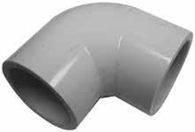
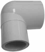
9 Assemble 5' Channels 2 1. ASSEMBLE THE CHANNELS (5') Place one 5' channel (115123) on a bench or saw horses. A Channel (5') B 2. Using adhesive, attach a plain end cap (no outlet ) to one end and an end cap with an outlet (110824) to the other end. Coat channel ends with adhesive before you install end caps. 3. Repeat the process for all channels. Set channels aside to allow adhesive to dry. 4. Next, attach a 90 elbow (WF6682) to each end cap as shown. Apply a thin film of pvc cement (WF6990) to the end cap outlet and slide the fitting onto the outlet. Install fitting as shown with open end pointing down in the 6:00 o'clock position. Wipe excess cement from around the fitting. C WF6682 Elbow D ATTENTION: Verify that you are using the WF6682 elbows that do not have threads. Do not use the WF6692 elbow. 5. Once all end caps and drain elbows are in place, carefully flip all channels over so bottom faces up and open top faces down. 6. Apply adhesive along edges to secure end caps to each 5' channel. Photos show an end cap with an outlet. Secure plain end caps in the same manner. E open top-inside channel WF6682 Elbow WF6990 F Apply cement in a well-ventilated area. Read the container information for additional precautions. NOTE: Coat all edges and seams of end caps to prevent leaks. 7. Allow adhesive to dry before moving the channels or testing the system. G H 8. Continue by installing the 2" hangers. bottom 9

10 3 INSTALL 2" DRAIN MANIFOLD HANGERS Install 2" Pipe Hangers Channel Support Tube Complete these steps Tek Screw Nut Setter " Hanger Horizontal Frame Brace 1. Determine which direction you want the drain manifold to slope toward and attach high end pipe hanger first. See A. NOTE: Attach hanger flush with top edge of channel support tube and flush with inside edge vertical frame tube. Secure hangers to frame using Tek screws and the driver. A Channel Support Tube B Install hanger flush to top of support tube. A Support Tube B Vertical Tube 1/4" to 3/8" down from top of tube. Attach hangers here. Channel Support Tube Vertical Tube Install hanger flush to inside of vertical tube. Install hanger flush to inside of vertical tube. High End of Drain Manifold Low End of Drain Manifold 2. Move to low end and attach hangers 1/4" down from top edge of support tube and flush to the inside of vertical frame tube. See B. 3. Repeat for all remaining 2" drain hangers. High End Channel Support Tube End View of Main Frame Drain this direction. Frame brace is not shown. Low End Horizontal Frame Brace 10
11 4 ASSEMBLE AND ATTACH 2" PVC DRAIN MANIFOLD Complete these steps: Assemble and Attach 2" PVC Drain Manifold 1. Cut one piece of 2" pvc pipe to 53" and snap it into the hangers at one level of the frame. ATTENTION: Center pvc pipe so 1" extends past outer edge of vertical frame tube at each end. ATTENTION: During the assembly of the 2" drain manifold, dry fit all pvc tubing and fittings before applying pvc adhesive to check overall fit. 2. Rotate pipe in the hangers so the printing on the pvc is centered on top. (Printing is used to maintain alignment when drilling holes.) Mark the inside edge of each hanger on the pvc pipe as shown. Marks are used to realign pipe with hangers after drilling. 3. At one pipe end, measure 5-1/4" in from hanger and mark. This is the position of the first drain hole. 4. From the mark in Step 3, measure and mark the on-center locations for the drain elbows of all channels. See diagram for on-center dimension. Step 2: Mark pvc. Step 3: Mark pvc first hole location. Step 2: Mark pvc. 1" 5-1/4" 7-1/2" 7-1/2" 7-1/2" 7-1/2" 7-1/2" 5-1/4" 53" ATTENTION: Check hole positions before the next step! There should be six (6) hole positions marked on the tube when finished. Holes should be evenly spaced and equal distance from each end of the pvc tube. Measure and remark if holes are not marked correctly. Diagram shows pvc tube with drilled drain holes and channels on support tube. Channels are added in a later procedure. Diagram is not to scale. 11
 holes in the 2\" tube. Example shows using a step bit to drill the holes.")


12 Assemble and Attach 2" PVC Drain Manifold 4 ASSEMBLE AND ATTACH 2" PVC DRAIN MANIFOLD continued 5. After confirming hole positions, use a 1-3/8" hole saw bit to drill the six (6) holes in the 2" tube. Example shows using a step bit to drill the holes. Keep all holes aligned during this step; use the printing on pipe if possible. NOTE: Pvc pipe can remain clamped in the hangers, or it can be removed and drilled off the rack. If you leave it clamped to the rack, block the center of the pipe or have an assistant hold it to prevent damage to the pipe hangers. For best results, drill pvc in a drill press if possible. To release the pvc pipe from hanger, press pipe into hanger and use a small screw driver to release hanger jaws. Hangers will release easily. Be careful not to damage the locking teeth of hanger jaws. Place a 2" x 4" under the center to brace pipe if drilling holes when attached to hangers. Photo shows using a step bit to drill holes in the pvc pipe. Photo shows using a hole saw bit to drill holes in pvc pipe. 6. After drilling the pipe, remove all pvc debris and clean inside the tube. If pipe was drilled on rack, remove it from the lower level and install at the upper level after cleaning. Use the lower level hangers to hold and drill pipe. Diagram below shows top view of pvc pipe after drilling drain holes. 7. Repeat these steps to prepare, drill, and clean the remain three (3) horizontal 2" pvc drain pipes. Center Line 12
. Dry fit all components before you permanently secure with WF6990 pvc cement if desired.")
13 4 ASSEMBLE Assemble and Attach 2" PVC Drain Manifold AND ATTACH 2" PVC DRAIN MANIFOLD continued 8. Attach all prepared pvc tubes to the frame. Align marks made in Step 2 with the installed hangers. See left diagram below. 9. Assemble remainder of main drain manifold as shown in diagram below (right). Dry fit all components before you permanently secure with WF6990 pvc cement if desired. Apply a thin film of cement to each component and assemble. Wipe excess cement from fittings and allow cement to set. ATTENTION: Do not glue WF6717 slip caps to horizontal tubes. These caps are removed to periodically clean drain manifold as needed. 10. Continue with tank preparation. High end of drain manifold. Low End WF1576 WF6717 ATTENTION: Do not glue the WF6717 fittings to the pvc pipes. 2" pvc pipe cut to the required length. 2" PVC WF1386 2" PVC WF1386 WF6990 PVC Cement 13


14 5 DRILL RESERVOIR AND LID AND INSTALL FITTINGS Required tools: Drill, 5/16" drill bit, 2-1/4" and 2-1/2" hole saw bits Reservoir and Lid Preparation ATTENTION: Actual reservoir and lid may differ from photo model. Procedures are similar. 1. Identify corner you want to drill the drain hole in reservoir lid. (When reservoir is in position under frame, this is the corner closest to drain manifold outlet.) Drill drain hole using a 2-1/2" hole saw. Do not drill cover over reservoir. Debris can damage pump and clog the filter once system is operating. 2. Next, using a 5/16" drill bit, drill hole through the lid for air pump tubes. See photo below. 2-1/2" Drain Pipe Hole x Actual lid and reservoir may differ slightly from what is shown in this example. STEP 1: The X marks hole location based on reservoir design and position. Drill one 2-1/2" drain hole in corner. Move cover off reservoir. Place on support to drill the 2-1/2" drain hole. Photo shows sample reservoir with drain hole in lid. ATTENTION: Actual lid and reservoir may differ. Raised areas may not be present on actual lid. Drill holes as directed and in same area on the lid. STEP 2: Drill holes for air pump tubes using a 5/16" drill bit. Drill cover off reservoir. Drain Manifold Outlet Photo shows drain hole in reservoir lid with reservoir in position under frame. 14
 to determine on which side of the reservoir you want to install pump and related fittings. 4.")


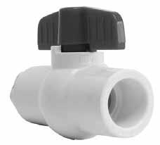
15 5 DRILL Reservoir and Lid Preparation RESERVOIR AND LID AND INSTALL FITTINGS continued 3. Review diagrams in Quick Start section (back of guide) to determine on which side of the reservoir you want to install pump and related fittings. 4. Take a WF2193 adapter, a WF1570 elbow, and a 1-1/2" to 2" section of 1" pvc tubing and dry fit these together. See photos. Do not glue at this time. Thread assembly into WF8582 bulkhead fitting and place assembly against side of reservoir to judge bulkhead fitting and pump position. NOTE: Pvc tube must be short enough to keep bulkhead fitting low on side of reservoir and long enough to allow top outlet of pump to clear tank. Shorten pvc tube as needed to keep bulkhead fitting low on reservoir while still allowing pump to remain flat on floor. Pump Outlet Reservoir Drain End WF1570 Elbow 1" PVC Tube WF2193 Pump WF1570 WF2193 Do not drill hole too low on tank. Verify pump alignment. Reservoir End A Outlet Tube A: Pump outlet tube must clear lid when installed. WF8582 Bulkhead 5. Raise or lower assembly on side of reservoir as needed to align elbow with intake port of pump. Adjust as needed to ensure pump is set as close to reservoir as possible without contacting lid when supply plumbing is installed. Mark fitting location on side of reservoir and drill bulkhead fitting hole using a 2-1/4" hole saw bit. Review all photos and diagrams as needed for details. Pump outlet pvc tube must clear edge of reservoir lid. 15


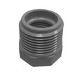
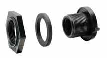
16 5 DRILL Reservoir and Lid Preparation RESERVOIR AND LID AND INSTALL FITTINGS continued 6. After drilling hole in reservoir, attach the WF2392 bushing, extension, and screen to threaded body of WF8582 bulkhead as shown below in left column. Hand tighten until snug. Do not tighten with tools. 7. Attach fitting assembly to reservoir. Install hex nut and thin flat washer (if equipped) outside reservoir. Install screen, extension, and thick rubber seal inside reservoir. Tighten until snug using large adjustable pliers. 8. Disassemble WF2193 adapter, WF1570 elbow, and section of 1" pvc tubing from previous page and reassemble using pvc cement to secure all pvc joints. Wrap adapter threads with sealing tape and attach assembly to installed bulkhead. Tighten until snug. Hold bulkhead if needed when tightening the connection. 9. Continue with the next procedure. Hand-tighten only Screen Extension WF1570 Elbow WF2392 Bushing Rubber Seal Top View Install rubber seal inside reservoir. Holes for air stone tubes. Porthole View Inside Reservoir Drain End Drain Hole 16


 5/16\" holes in each lid where plant hole is closest to lid end. See diagram that follows. Keep lids in the same group when completed.")
17 5 DRILL NUTRIENT TUBE HOLES IN LIDS AND INSTALL LIDS Complete these steps to drill holes for nutrient tubes: Reservoir and Lid Preparation For improved plant growth, off-set holes when installing lids. Alternate lids as shown below and on previous page. Before snapping lids onto channels, drill the nutrient tube holes at one end of each lid. 1. Take half of the channel lids and arrange so all plant holes and ends align. Take the remaining channel lids and repeat this step. Keep the two piles separate. ATTENTION: For the first pile of lids, position nutrient tube holes where first plant hole is closest to the lid end. See A in the photo. For the remaining lids, position nutrient tube holes where first plant hole is farthest from lid end. See B in the photo. 2. Move to pile A and drill two (2) 5/16" holes in each lid where plant hole is closest to lid end. See diagram that follows. Keep lids in the same group when completed. A Nutrient Tube Holes B Photo shows lids installed so plant holes are offset. Space holes 2" apart. Hole closest to end. 1/2" to 3/4" from end. A 2" Spacing 3. Move to pile B and drill two (2) 5/16" holes in each lid where plant hole is farthest from lid end. See diagram that follows. Keep lids in the same group when completed. Space holes 2" apart. Hole farthest from end. B 1/2" to 3/4" from end. ATTENTION: Example above continues the example shown on previous page. Actual hole pattern may not resemble what is shown in this example. Whatever the hole pattern, when sliding lids onto channels, position nutrient tube holes opposite the drain end/elbow of the channel. ATTENTION: Drill holes away from open channels to prevent debris from dropping into channels. 17
18 Reservoir and Lid Preparation 5 DRILL NUTRIENT TUBE HOLES IN LIDS AND INSTALL LIDS continued Tek Screw Hanger 4. Move to supply manifold end of the frame (opposite drain manifold) and attach one hanger in each position shown below using Tek screws and driver. Do not overtighten! 5. Wipe shavings from each lid (top side and underside). Slide a lid onto each channel and arrange channels on assembled frame as shown. Position all nutrient tube holes opposite the channel drain elbow. Step 4 Step 5 A B A B A B A B 9" 9" Hanger Top View of Channels 6. Continue with the assembly and installation of nutrient supply manifold. ATTENTION: Actual number and size of holes may differ and depends on growing needs. 18
19 Assemble and Install Nutrient Supply Manifolds 6 ASSEMBLE AND INSTALL NUTRIENT SUPPLY MANIFOLDS CONTINUED Complete these steps: 1. Gather the parts and construct one (1) upper manifold pipe and three (3) lower manifold pipes. Dry fit all parts. Do not glue at this time. WF1570 WF4135 (1" PVC PIPE) Upper Supply Manifold WF6692 ATTENTION: Cut the 1" pvc pipe short enough to allow approximately 1/2" clearance at each end when fittings are installed. WF1380 WF4135 (1" PVC PIPE) Lower Supply Manifold WF6692 Remove cross brace if needed during manifold install. One (1) Upper Supply Manifold: Elbow at each end. WF1380 WF4135 (1" PVC PIPE) Lower Supply Manifold WF6692 Three (3) Lower Supply Manifolds: Tee at one end; elbow at the other. WF1380 WF4135 (1" PVC PIPE) Lower Supply Manifold WF Snap the upper manifold into place on the frame. (Remove cross brace if needed for easier installation.) Snap lower manifolds into place on lower three levels. 19

20 Assemble and Install Nutrient Supply Manifolds 6 ASSEMBLE AND INSTALL NUTRIENT SUPPLY MANIFOLDS CONTINUED 3. Align and evenly space all channels at each level. Channels will run parallel with each other and the 55" frame tubes. Insert drain elbows into drain manifold to keep channels in place. 4. With all manifolds snapped into place on the frame, mark the center of each manifold along its length using a chalk line. You can also rotate the pvc pipe so the printing shows. Use non-permanent chalk. Remove frame cross brace to install manifold. Step 4: Mark center of each pipe. Step 5: 2" Hole Spacing Chalk line Mark here to keep fitting in the same place. 5. Using a marker, mark two (2) hole locations for each channel on each manifold pipe. Mark holes in the center of the manifold pipe. Space 2" apart. 6. After holes are marked, mark each fitting to more easily reassemble the manifolds after drilling the holes and cleaning the pipe. 7. Once manifolds are marked, carefully remove each manifold from the frame. Use a small screwdriver to carefully release pipe hanger jaws. If desired, mark frame level (1, 2, or 3) on each of the lower manifolds to reinstall them in the same location. Step 6: Mark fitting positions for reassembly. 20


21 Assemble and Install Nutrient Supply Manifolds 6 ASSEMBLE AND INSTALL NUTRIENT SUPPLY MANIFOLDS CONTINUED 8. Choose one manifold and place it on a flat surface with the marks facing up. Upper manifold is shown below Drill & Tap Combo Pak 9. Using the drill bit from the drill and tap combo pak, drill a hole at each of the marks. For best results, drill the manifold using a drill press. Repeat this step to drill the remaining supply manifolds. 10. After drilling the holes in all manifolds, use the tap from the combo pak to tap threads in each hole. Use a reversible drill. Do not use a drill press. Slowly turn tap into hole. Do not allow it to bottom out in the pvc tube. After tapping the hole, reverse the drill and back the tap out. Keep the drill steady and straight during this process. ATTENTION: Use a reversible, variable speed drill for this step! If one is not available, use a socket to hold the tap and turn it with a ratchet. Center tap in the hole and turn it slowly to tap threads. Do not allow tap to contact the inside wall of the pvc tube. Once threads are tapped, slowly back tap out of hole while keeping drill straight. Tighten tap in drill chuck. 11. Next, disassemble each manifold and clean the pvc pipe to remove debris from inside the tube. Keep parts for each manifold together. 21


22 Assemble and Install Nutrient Supply Manifolds 6 ASSEMBLE AND INSTALL NUTRIENT SUPPLY MANIFOLDS CONTINUED 12. Wrap threaded end of each adapter three or four times with WR1095 thread-sealing tape. Wrap in a direction that will not loosen when adapter is installed. There are 48 adapters needed for this system. WF4790 Key Punch Adapters WR1095 Tape WF6990 PVC Cement Wrap threads of adapters with tape. Install adapters using WF4790 key punch. 13. Using the WF4790 key punch, carefully install the adapters in each of the manifold pipes. Do not overtighten! Adapters will snap off. Once slight resistance is felt during installation, stop tightening the adapter. 14. Apply a thin film of WF6990 pvc cement to each end of one manifold pipe and reassemble the manifold using the fittings for that pipe. Use the marks to position the fittings as they were before manifold was disassembled. Set the assembly aside and repeat the step to reassemble all manifolds. Allow the cement to set before continuing with the next step. Alignment Marks 22

23 Assemble and Install Nutrient Supply Manifolds 6 ASSEMBLE AND INSTALL NUTRIENT SUPPLY MANIFOLDS CONTINUED 15. Assemble the four (4) valve assemblies as shown AC Clamps Step 18: Measure distance needed to connect manifolds. Pipe must be long enough to insert into each fitting. 16. Wrap the threads of each adapter four or five times with WR1095 thread sealing tape. Wrap in a direction that will not loosen when installed in the threaded elbows of the supply manifolds. 17. Take one valve assembly and thread it into the threaded elbow fitting at the end of a manifold assembly. Tighten until snug. Repeat to install all remaining valve assemblies. Valves will all be at the same end when manifolds are attached to the frame. Upper Manifold Assembly Lower Manifold Assembly 18. Snap upper manifold and first lower manifold assemblies into place. Measure length needed for the first vertical pvc pipe and cut a piece of 1" pvc pipe to that length. Remember to allow enough length for the pipe to connect the two supply manifolds. Do not cut the pipe too short. Dry fit the pipe before adding pvc cement if needed. 23
24 Assemble and Install Nutrient Supply Manifolds 6 ASSEMBLE AND INSTALL NUTRIENT SUPPLY MANIFOLDS CONTINUED 19. After confirming length, disassemble as needed to apply pvc cement and reassemble. Remove and reinstall lower manifold as needed. 20. Continue working down the end frame and adding the 1" vertical manifold pipes. Dry fit all pipes before applying pvc cement. 21. Reinstall frame cross brace if needed. 22. Continue with next procedure. Step 21: Reinstall cross brace. WF6990 PVC Cement Step 19 WF6990 PVC Cement Step 20 Step 20 24


 for a suggested tube pattern.")
25 7 CUT Cut and Install 1/4" Nutrient Supply Tubes AND INSTALL 1/4" NUTRIENT SUPPLY TUBES Complete these steps: 1. Determine the desired 1/4" tube length. Tube should reach from adapter in supply manifold to a hole in the channel lid immediately above adapter pair. 2. Adjust tube length as needed and cut remaining tubes from the A bulk roll. There are 48 tubes for this system. Use a scissors or utility knife to create a clean, smooth cut. Step 1 & 2 Step 3 & 4 Step 5 3. Once all tubes are cut, determine where you want to install the micro valve in the tube. Cut the tube in two at that position. See photo upper right for a complete assembly. 4. Slide the two pieces of tubing onto the micro valve. Cut tube end at an angle. 5. Move to the assembled frame and slide one end of a tube assembly onto an adapter in the manifold. Adapters are fragile! Wet the tube end for easier installation. 6. Take free end of the same tube and slide it into hole of channel lid. Review photo (upper right) for a suggested tube pattern. Diagram to the right shows another tube installation pattern. Trim the tube end at an angle for easier installation. 7. Repeat the steps to assemble and install all remaining 1/4" nutrient supply tubes Step 6 Photo shows one level of the lettuce system with nutruient tubes installed. 25
26 8 LEVEL FRAME AND SET SLOPE To ensure that water flows through and properly drains from the plant channels, a 1-1/2" to 2" slope toward the drain end of the system is required. Frame must also be level from side-to-side when viewed from the end. Complete these steps: 1. Move frame to the location where it will be used if this has not been done. Level Frame and Set Slope 2. At drain (low) end of frame, adjust the adjustable feet to lower that end as much as possible. Allow enough room between top of each foot and locking nut to make final adjustments and to lock feet in position. Set a level on the lower frame cross brace and check. Adjust side-to-side frame position so frame is level. See end frame diagram below. ATTENTION: Example below shows a system setting on a 3. Move to supply end of frame and raise that end to achieve required slope. level finished grade. If finished grade is sloped, make the 4. Level frame side-to-side after setting end-to-end slope. necessary adjustments in calculations to account for any differences. When slope is properly set, frame should slope 5. Recheck frame slope. Verify that ends are level. Tighten locking nuts to secure feet. 1-1/2" to 2" from supply end down toward drain end. Drain Drain End X" X" + 1-1/2" to 2" Side View Ground Level End View 26
27 9 INSTALL MAIN PUMP & PLUMBING Connect Main Pump to Supply Manifold Gather parts identified in the diagram and construct main pump supply plumbing. Review assembly and installation notes that follow before you begin. For best results, complete this procedure after setting frame slope. When possible, dry fit all connections before applying pvc cement to better judge required length. Install the WF1030 Y-filter with the water-flow direction arrow pointing away from pump as shown. Position reservoir so pump and related plumbing remain under or aligned with frame. WARNING: All electrical wiring to be completed by a qualified electrician according to recognized local building codes. 1/4" nutrient tube connecting supply manifold to channel. Drain Manifold End WF1570 water flow Drain 1" PVC WF WF2190 WF WF6682 Supply Manifold End WF1380 tee fitting at end of pvc supply manifold. NOTE: Secure pump to mounting surface to reduce vibration. WF Unions 1" PVC *Actual configuration of fittings may differ depending on overall layout, pump position, and personal preference. Diagram not to scale. It is possible that some parts will remain unused. 27


28 10 ASSEMBLE Assemble and Attach 2" PVC Drain Manifold AND ATTACH PVC DRAIN MANIFOLD Complete these steps: 1. Measure, cut, and dry fit the remaining sections of the 2" pvc drain manifold as shown in the photos below. 2. Once the fit is confirmed, disassemble and apply a thin film of WF6990 cement to drain tubes and fittings. See below. ATTENTION: Do not glue the extension tube that extends through the lid from the WF1576 elbow. Extension tube must remain free to remove for routine tank maintenance. 3. Allow the cement to set and continue with following procedure. WF1576 Glue No Glue! Glue Minimum 6" tube. Tube should extend through lid at least 2" but remain above solution level. WF1576 2" PVC 2" PVC WF1576 WF1576 WF


29 Install the Air Pump and Tubing 11 ATTENTION: Always position the air pump above the nutrient level to prevent siphoning of the reservoir. ATTACH AIR PUMP AND AERATOR STONES For optimal system performance and to extend the life of nutrient solution through increased oxygenation, an aerator pump and aerator stones are included. Position stones on reservoir bottom opposite water pump. Air pump must remain above nutrient level to prevent siphoning. 1. Choose a position for the air pump and use it to determine length of each air tube. Cut two air tubes of equal length using tubing. ATTENTION: Position air pump at a level that is above the nutrient level at all times to prevent siphoning of the reservoir in the event of a power outage. 2. Attach one stone to each line and set the stones in the reservoir. 3. Place reservoir cover on the reservoir and feed the tubing up through the access holes. Connect the free end of each tube to the air pump. 4. Place air pump in the position chosen in Step 1. Attach tube to air stone Air Stone Air Tube 5. Connect air pump to power and test operation. Verify that air is filtering through each air stone. Monitor air pump regularly to ensure proper operation of aerator system. NOTE: When system is fully operational, air pump will run continuously. Do not connect air pump to any circuit controlled by a timer or shutoff switch. 6. After testing air flow, turn off aerator pump until system is fully functional. *Actual reservoir size may differ. 29
30 Basic System Check & Operation 12 WARNING: KEEP ALL ELECTRICAL CORDS AND CONNECTIONS OUT OF RESERVOIR. CONSULT THE SERVICES OF A QUALIFIED ELECTRICIAN TO ADEQUATELY AND SAFELY CONNECT PUMPS TO POWER. ALL ELECTRICAL CIRCUITS SHALL BE DESIGNED IN ACCORDANCE WITH LOCAL AND REGIONAL BUILDING CODES AND STANDARDS. Basic System Check and Operation Complete these steps to check and start up the system: 1. Verify that all electrical cord ends are outside reservoir. 2. Ensure that all 1/4" supply tubes are fully inserted in channel lids and that all micro valves are open. 3. Verify that drain elbow of each channel is fully inserted into drain manifold. 4. Add water to reservoir through porthole until reservoir is at least half full. 5. Verify that 2" drain manifold extension pipe is inserted through reservoir lid. 6. Verify that the AC2804 valve at the end of each supply manifold is closed. 7. Open the two (2) WF3316 in-line ball valves. One is between reservoir and water pump; one is after/above water pump. 8. Turn on water and air pumps. 9. Check each channel to ensure that water is running out each 1/4" supply tube and drain end of each channel. If water flows from all tubes at all levels, continue with next step. If water is not flowing through all tubes, turn off pump and complete the "Prime the Pump" procedure that follows. Prime the Pump AC2804 WF3316 a. Slide cover off reservoir, reach inside, and remove screen from bulkhead fitting. See diagram (left). b. Attach a hose to water faucet and place hose end in front of bulkhead fitting inside tank. Hose attached to faucet. Nutrient Level Pump Bulkhead c. Open hose faucet and turn on pump. Pump sound will change when pump is primed and pumping. d. Check all levels of system for water flow. e. Remove hose, reinstall screen, and set cover in place on reservoir. 10. Check all plumbing connections main supply line and filter for leaks. Check all pump fittings for leaks. 11. Check all pvc fittings for leaks. 12. Look for bubbles in the reservoir to verify that the air is pumping to each air stone. Remember to always mount the air pump on a surface that is above the water level. Vibrations of air pump can cause it to move. Make sure pump does not fall into reservoir or other liquids. 13. Once system is checked and all adjustments made, it is ready to use. 30


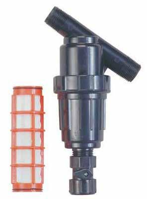
31 Operational and Maintenance Information General Cleaning and Maintenance Instructions For optimal performance and to increase yields, check and clean the system periodically. Time between maintenance and cleaning depends on the growing environment and specific use of the system. Complete the following steps as needed to ensure that your system is working properly. 1. Inspect the frame and mounting screws to ensure they are tight and frame is not damaged. 2. Disconnect the main power supply to turn off all pumps. Remove the reservoir cover and inspect the inside of the reservoir. Reservoir should be cleaned each time the nutrient solution is changed. Keep the reservoir and porthole covers in place during operation to prevent light from entering the reservoir. 3. Check all plumbing and main supply connections to ensure that all are operating as designed. No leaks. 4. Replace worn or cracked supply tubes as needed. 5. Clean the drain tube if needed. Remove the end plugs and inspect the inside of the tube. Clean the drain tube by pulling or pushing a brush or cloth through the it. Rinse with clean water. Clean the Filter Screen and Housing For best results, clean the filter screen regularly or when the flow rate changes unexpectedly. Complete these steps to clean the filter screen. Flow 1. Shutoff the power to the nutrient pump. Open the valve on the filter to drain into a bucket. Flow 2. Grip the filter housing and the main supply line and unscrew the housing. Do not apply force to the filter fittings. NOTE: Do not allow debris from the drain tube to contaminate the contents of the reservoir. Remove extension tube before cleaning. 6. With the pump off, disassemble the filter and clean the screen and housing. Reassemble for use. See procedure in the right column. 3. Remove the screen from the housing. Using clean water, rinse the housing and the screen. 4. Insert the screen back into the housing, reassemble the filter, and close the valve. 5. Turn on the pump and check the flow from the supply tubes to each channel. 6. Check filter and fittings for leaks. ATTENTION: Actual system may differ from the example shown. Photos are provided for filter cleaning only. They do not shown actual system. 31


32 Operational and Maintenance Information RESERVOIR CLEANING AND MAINTENANCE Clean the reservoir periodically to maximize plant growth and to minimize system contamination. The steps that follow can be used to change nutrient solution and to pump the reservoir for cleaning and typical maintenance. Cleaning the filter is strongly recommended after cleaning the reservoir. Shutoff Valve 1. Turn off the nutrient pump and connect a garden hose to the shutoff valve of the filter. Place the end of the hose in a bucket or run it to the desired location. 2. Open the shutoff valve on the filter and turn the pump on to pump out the reservoir. Turn off the pump once the reservoir is empty. 3. Clean reservoir. Repeat steps to pump it out if needed. 4. Close the shutoff valve. 5. Remove the hose and clean the filter. See previous page for filter cleaning procedure. 6. Refill the reservoir with nutrient solution. Turn on the pump to resume operation. Check all fittings, tubes, and filter for leaks. 32
33 Quick Start Guide Sample System Fully Assembled 33
34 Frame Dimensions End View Frame (Width) Side View Frame (Length) Width Approximately 51" (frame only) Length Approximately 58" (frame only) 16" Height approximately 80" (no feet) 16" 16" Approximately 24". Actual distance depends on adjustable feet settings. 34

35 Full Frame Diagram ATTENTION: The vertical tubes include holes of two different diameters. Install larger hole to the outside to allow flat head bolt to sit flush with tube surface when installed. 55" Side Tube FD15LMGL05500S1 48" Cross Brace FD15CMGL04800S Finishing Cap Finishing Cap 80" Corner Tube FD15VMGL08000S4 55" Side Tube FD15LMGL05500S /16" x 3" Flat Head Bolt Use this flat head bolt for all vertical corner tube connections. 48" Cross Brace FD15CMGL04800S1 FAME51B FAG338B S01 Adjustable Foot Use this hex bolt and washer combination for all cross brace connections. 35
36 Supply & Drain Manifolds Only* Supply Manifold Drain Manifold *Actual fitting configuration may differ depending on overall layout, pump position, and personal preference. Diagram not to scale. 36
37 End View 1" Supply Manifold with Channels* WF1570 (1) (Micro Valve) WF4135 (1" PVC PIPE) A A (Tubing) WF6692 (1) Adapter 1" PVC Manifold (1) (1) (1) AC2804 (1) WF4135 (1" PVC PIPE) WF1380 (3) Reservoir with Lid *Diagram not to scale. 37
38 End View 2" Drain Manifold with Channels WF6717 (4) WF (8) WF1386 Assembled Channel (2" PVC PIPE) (2" PVC PIPE) Minimum 6" tube. Tube should extend through lid at least 2" but remain above solution level. WF1576 WF1576 Reservoir with Lid *Diagram not to scale. 38
39 Side View with Channels ATTENTION: Use this information when system is in operation: A: Adjust this valve to control nutrient flow to the channels. B: This valve to remain fully open during operation. Close it to service or remove pump. WF3316 A WF3420 WF2190 WF WF1380 WF3316 ATTENTION: WF3316 valves are shown in the "open" position during system operation. Never close valves when system is in use WF3316 Actual tank and pump may differ from example shown. *Diagram not to scale. B 39

40 Additional Photo ATTENTION: Photo shows a larger system with a light kit installed. Contact your sales representative to purchase a light kit for your system. Actual tank and plumbing components may differ from those shown in the photo. Assembly is similar. Shown for example. 40
41 Customer Notes and Records 41
HydroCycle 6" Pro NFT Lettuce Systems
 HydroCycle 6" Pro NFT Lettuce Systems Designed to grow healthy plants without soil using mineral-nutrient solutions. 2016 Growers Supply All Rights Reserved. Reproduction is prohibited without permission.
HydroCycle 4" Pro NFT Lettuce Systems
 HydroCycle 4" Pro NFT Lettuce Systems 112251 Hydroponic Lettuce Table* Designed to grow healthy plants without soil using mineral-nutrient solutions. *Actual system may differ from what is shown. 2016
FodderPro 3.0 Commercial Feed Systems
 FodderPro 3. Commercial Feed Systems 112712 "...grow your own nutrient-rich fodder..." 16 FarmTek All Rights Reserved. Reproduction is prohibited without permission. Revision date: 12.2.16 *Actual system
Breathable Wall Light Traps
 Breathable Wall Light Traps 2017 Growers Supply All Rights Reserved. Reproduction is prohibited without permission. Maintain controlled airflow without sacrificing blackout environments. BREATHABLE WALL
ClearSpan Curtain Tube Support System (Manual Gearbox)
") ClearSpan Curtain Tube Support System (Manual Gearbox) ATTENTION: This guide describes the assembly and installation of roll-up curtains. The design flexibility of these curtain systems allow for a variety
ClearSpan Curtain Tube Support System (Manual Gearbox) ATTENTION: This guide describes the assembly and installation of roll-up curtains. The design flexibility of these curtain systems allow for a variety
ClearSpan Curtain Tube Support System with Electric Drive Motor (300w)
") ClearSpan Curtain Tube Support System with Electric Drive Motor (300w) TTENTION: This guide describes the assembly and installation of roll-up curtains. The design flexibility of these curtain systems
ClearSpan Curtain Tube Support System with Electric Drive Motor (300w) TTENTION: This guide describes the assembly and installation of roll-up curtains. The design flexibility of these curtain systems
Installation Instructions Table of Contents
 Installation Instructions Table of Contents Pre- Installation of Garage Storage Lift 2 Layout the Garage Storage Lift 3 Installing the strut Channels 3 Install the Drive Assembly 5 Install the Drive Shaft
A B C D E F. Tools Required (supplied by others)
") Page 1 of 17 Parts List Below Deck Automatic Retractable Security Cover Kit (1) Tube End Bearing Plate (A) (1) Rope Reel and Cover Drum Motor Assembly (B) (1) Cover Drum (1) Pulley Support Channel (2)
Page 1 of 17 Parts List Below Deck Automatic Retractable Security Cover Kit (1) Tube End Bearing Plate (A) (1) Rope Reel and Cover Drum Motor Assembly (B) (1) Cover Drum (1) Pulley Support Channel (2)
FOR FUTURE REFERENCE SERIES 93HPS
 Hypro Series 93HPS Hydraulically Driven Wetseal Multistage Pumps Repair Manual KEEP FOR FUTURE REFERENCE Form L-1578R Rev. A SERIES 93HPS Hydraulically Driven Stainless Steel Multistage Centrifugal Pumps
INSTALLATION INSTRUCTIONS Part# , , ,
 INSTALLATION INSTRUCTIONS Part# 20-0218, 22-0318, 20-0118, 22-0219 20-0218 - 4 Tire On Board Air Delivery System and Dual Compressed Air System Includes ARB CKMTA12 Compressor 20-0118 - 2017 FORD RAPTOR
INSTALLATION INSTRUCTIONS SERVICE MANUAL
 INSTALLATION INSTRUCTIONS SERVICE MANUAL This manual provides instructions for the proper installation of the L 06 HAWLE stair lift. It is necessary to read and understand the contents of these instructions
Important: Please read these instructions carefully and completely before starting the installation. TITAN Fuel Tanks INSTALLATION GUIDE
 TITAN pt. no.: 03 0000 0128 Important: Please read these instructions carefully and completely before starting the installation. TITAN Fuel Tanks INSTALLATION GUIDE 30 Gallon* Spare Tire Auxiliary Fuel
D-04/G-04 Maintenance
 D-04/G-04 Maintenance NOTE: The numbers in parentheses are the Ref. Nos. on the illustrations in the Parts Manual. Daily Check the oil level and the condition of the oil. The oil level should be 1/4 in.
M-8100EP. Installation Guide ENGINEERED PLASTIC MANIFOLD SERIES. Introduction. A. Assemble Manifold Components
 Introduction The Pro Manifolds with Integrated adaptor are designed for use in Hydronic radiant panel heating and cooling applications. They are available in various sizes, configurations, and options
A B C D E F. b.tools Required (supplied by others) 3/16" Drill Bit 3/8" Wrench Phillips Head Screwdriver
 3/16 Drill Bit 3/8 Wrench Phillips Head Screwdriver") Page 1 of 13 5E.1 Parts List a. Below Deck Automatic Retractable Security Cover Kit (1) Tube End Bearing Plate (A) (1) Rope Reel with Motor Attached (B) (1) Rope Reel Cover (C) (1) Cover Drum (1) Cover
Page 1 of 13 5E.1 Parts List a. Below Deck Automatic Retractable Security Cover Kit (1) Tube End Bearing Plate (A) (1) Rope Reel with Motor Attached (B) (1) Rope Reel Cover (C) (1) Cover Drum (1) Cover
INSTALLATION INSTRUCTIONS
 INSTALLATION INSTRUCTIONS REAR DISC BRAKE CONVERSION KIT A126-1 1973-87 CHEVROLET 1/2 TON 2WD Thank you for choosing STAINLESS STEEL BRAKES CORPORATION for your braking needs. Pleases take the time to
Duramax Lift Pump Kit 9-11 PSI Installation Instructions P/N# D
 2001-10 Duramax Lift Pump Kit 9-11 PSI Installation Instructions P/N# 1050320D PLEASE READ ALL INSTRUCTIONS CAREULLY BEORE INSTALLATION Kit Contents 1500365-P2 1500330-D lowmax Lift Pump V3 lowmax Wiring
PRODUCT USE INFORMATION
 9RC61000 Jeep YJ Body Lift Thank you for choosing Rough Country for all your suspension needs. This body lift fits both manual and Automatic equipped vehicles!!! Refer to last page of this Instruction
INSTALLATION INSTRUCTIONS
 INSTALLATION INSTRUCTIONS Part# 69-0717 AIR IT UP 4 Tire On Board Installed Air Delivery System with Rear Mounted Controller (Requires External Air Source) For the most up-to-date instructions please visit
Roll Bar (MMRB-6.1 to -6.7)
") 3430 Sacramento Dr., Unit D San Luis Obispo, CA 93401 Telephone: 805/544-8748 Fax: 805/544-8645 www.maximummotorsports.com 1994-04 Roll Bar (MMRB-6.1 to -6.7) NOTE: These instructions cover Roll Bars with
3430 Sacramento Dr., Unit D San Luis Obispo, CA 93401 Telephone: 805/544-8748 Fax: 805/544-8645 www.maximummotorsports.com 1994-04 Roll Bar (MMRB-6.1 to -6.7) NOTE: These instructions cover Roll Bars with
NOTE: Visit our website at for video repair procedures, under the Tools section.
 Repair Instructions Hypro Repair Tools: Tool Box No. 3010-0168 1/4" Allen Wrench No. 3020-0008 Support Bars (2) No. 3010-0064 Port Brush No. 3010-0066 1/16" Allen Wrench No. 3020-0009 Brush Holder No.
Important: Please read these instructions carefully and completely before starting the installation. TITAN Fuel Tanks INSTALLATION GUIDE
 TITAN pt. no.: 01 0000 0136 Important: Please read these instructions carefully and completely before starting the installation. TITAN Fuel Tanks INSTALLATION GUIDE 30 Gallon* Spare Tire Auxiliary Fuel
Drag Race Roll Bar (MMRB-6, -7)
") 3430 Sacramento Dr., Unit D San Luis Obispo, CA 93401 Telephone: 805/544-8748 Fax: 805/544-8645 www.maximummotorsports.com 1994-04 Drag Race Roll Bar (MMRB-6, -7) The Maximum Motorsports 6-point Drag Race
3430 Sacramento Dr., Unit D San Luis Obispo, CA 93401 Telephone: 805/544-8748 Fax: 805/544-8645 www.maximummotorsports.com 1994-04 Drag Race Roll Bar (MMRB-6, -7) The Maximum Motorsports 6-point Drag Race
Additional Instructions for 6" Drop
 Serving the Truck & Trailer Industry Since 1944 Additional Instructions for 6" Drop Attention Dealers: Please give this manual to the customer when product is delivered. Call 800-535-9545 www.aeroindustries.com
Breathable Wall Light Traps
 reathable Wall Light Traps 2017 Growers Supply ll Rights Reserved. Reproduction is prohibited without permission. Maintain controlled airflow without sacrificing blackout environments. RETHLE WLL LIGHT
3.2 DRIVE TORQUE HUB. Roll, Leak and Brake Testing SECTION 3 - CHASSIS & TURNTABLE. 3-2 JLG Lift
 3.2 DRIVE TORQUE HUB Roll, Leak and Brake Testing 10 LUG PATTERN Torque-Hub units should always be roll and leak tested before disassembly and after assembly to make sure that the unit's gears, bearings
Important: Please read these instructions carefully and completely before starting the installation. TITAN Fuel Tanks INSTALLATION GUIDE
 TITAN pt. no.: 02 0000 0180 Important: Please read these instructions carefully and completely before starting the installation. TITAN Fuel Tanks INSTALLATION GUIDE 30 Gallon* Spare Tire Auxiliary Fuel
D-15/G-15 Maintenance
 D-15/G-15 Maintenance NOTE: The numbers in parentheses are the Reference Numbers on the exploded view illustrations found later in this manual and in the Parts Manual. Daily Check the oil level and the
Elite Skimmer Installation Manual. Manufacturers of Quality Pond Equipment & Supplies Item #PBESIM
 Elite Skimmer Installation Manual Manufacturers of Quality Pond Equipment & Supplies Item #PBESIM A C G B F E D H I A B C D Biological Waterfall Box Filters harmful waste and toxins from water, keeping
Installation Instructions
 Installation Instructions SELECTRONIC Proximity Infection Control Faucet 0 / 0 / 0 Infection Control Faucet shown Installed on American Standard. Infection Control Sink Certified to comply with ASME A..M
PRODUCT SAFETY NOTICE
 PRODUCT SAFETY NOTICE Congratulations. This vehicle has been equipped with a Firestone air suspension system. This suspension will enhance the vehicle s handling when loaded, however, the vehicle s performance
Section 13. Tail Rotor Drive. RotorWay International A600 TALON Construction Manual. Section 13. Page A
 RotorWay International Page A Tail Rotor Drive Procedures covered in this section: Install driveshafts and gearboxes; install drive belt and tensioner; fabricate and install tail rotor pitch actuator arms;
INSTALLATION INSTRUCTIONS
 28 INSTALLATION INSTRUCTIONS SECTION - AIR SPRING SECTION 2 - AIR ACCESSORY 2-5 ! IMPORTANT PLEASE DON T HURT YOURSELF, YOUR KIT OR YOUR VEHICLE. TAKE A MINUTE TO READ THIS IMPORTANT INFORMATION. This
Installation Instructions Z-Gate Shifter
 Installation Instructions Z-Gate Shifter Part Number 80681 1998, 2001 by B&M Racing and Performance Products The B&M Z-Gate shifter can be used in vehicles equipped with most popular three speed automatic
INSTALLATION INSTRUCTIONS REPAIR SEAL KIT PowerSurvivor 40E
 INSTALLATION INSTRUCTIONS REPAIR SEAL KIT PowerSurvivor 40E PURPOSE OF THE KIT The Repair Seal Kit should be installed after 1000 hours of operation. It should be installed regardless of whether or not
Tools Needed for Mounting Cleá Filling Station
 ALWAYS OBSERVE PRODUCT SAFETY AND HANDLING INSTRUCTIONS. ALWAYS DIRECT DISCHARGE AWAY FROM YOU or other persons. ALWAYS DISPENSE CLEANERS AND CHEMICALS AS DIRECTED ON THE LABEL. ALWAYS DISPENSE INTO APPROVED
Lifting height 5.5" - 72" with adapters " Height overall 165" Width between columns 122" Drive through 109" Width overall 151.
 Model Number TP12KC-D Capacity 12,000 lbs. Lifting height 5.5" - 72" with adapters 79.625" Height overall 165" Width between columns 122" Drive through 109" Width overall 151.125" Arm extension 37.5" -
Operation and Maintenance Instructions
 Operation and Maintenance Instructions One Research Drive Stratford, CT 06615 (203) 375-0063 www.sonicmixing.com 1 Installation and Start-up Do not perform following adjustments without disconnecting power
1.1 Quad Valve and Tri-Valve. Contents WATER DUMP BODY O-RING EXHAUST VALVE QUAD VALVE TIE WRAP EXHAUST MAIN BODY O-RING
 Quad Valve and Tri-Valve Exhaust Assembly on Fiberglass Helmets Quad Valve and Tri-Valve Exhaust Contents QUAD-1 QUAD-2 QUAD-2 QUAD-2 QUAD-6 QUAD-7 1.1 Quad Valve and Tri- Valve Exhaust Assembly on Fiberglass
INSTALLATION INSTRUCTIONS
 INSTALLATION INSTRUCTIONS FUEL SURGE TANK INSTALLATION KIT 1999-2006 BMW E46 COUPE Document# 19-0056 Support: info@radiumauto.com Note: This kit was designed for a standard single pump Radium Engineering
CONTENTS. Product Features and Specifications...1. Installation Requirement Steps of Installation.. 5. Exploded View Test Run...
 CONTENTS Product Features and Specifications...1 Installation Requirement... 3 Steps of Installation.. 5 Exploded View...18 Test Run...21 Operation Instruction...22 Maintenance... 23 Trouble Shooting...
2015 Mustang Lightbar (All Models) CDC#
 CDC#") 2015 Mustang Lightbar (All Models) CDC# 1511-7000-01 Components: 1 CDC Lightbar Note: READ instructions before starting installation!!! CDC Part# Driver side bracket 0511-6001-05 Passenger side bracket
2015 Mustang Lightbar (All Models) CDC# 1511-7000-01 Components: 1 CDC Lightbar Note: READ instructions before starting installation!!! CDC Part# Driver side bracket 0511-6001-05 Passenger side bracket
WJ AUTO TRANS. ATLAS SHIFTER
 KIT CONSISTS OF: No. Qty Part No. Description 4320 Aerotech Center Way, Page 1 of 8 1 1 302051 BASE- ATLAS TWIN STICK MOUNT 2 1 302080 STUD BOLT 1/2-13 X 7 B7 3 1 303120 Serrated-Flange Hex Locknut 1/2-13
INSTALLATION INSTRUCTIONS
 2807 INSTALLATION INSTRUCTIONS SECTION - AIR SPRING SECTION 2 - AIR ACCESSORY -6 ! IMPORTANT PLEASE DON T HURT YOURSELF, YOUR KIT OR YOUR VEHICLE. TAKE A MINUTE TO READ THIS IMPORTANT INFORMATION. This
INSTALLATION & OWNER S MANUAL
 Rev. B, p. 1 of 25 INSTALLATION & OWNER S MANUAL POLARIS RANGER RCS (for models XP or HD) (for model years 2009-) cab without doors kit (p/n 1POLRCWD) cab with doors kit (p/n 1POLRC) doors only kit (p/n
This suspension system was developed using a Maximum tire size of 33 X 12.5 with a 17 x 9 aftermarket wheel with 4 1/2-5 backspacing..
 92174700 Thank you for choosing Rough Country for your suspension needs. 2005-15 TACOMA 6 Kit Rough Country recommends a certified technician install this system. In addition to these instructions, professional
WET WALL. EvApORATIvE COOLINg SySTEm. 10" x 8" Tee INSTALLATION INSTRUCTIONS
 WET WALL EvApORATIvE COOLINg SySTEm 10" x 8" Tee INSTALLATION INSTRUCTIONS 800-779-3267 sales@schaeferfan.com www.schaeferfan.com 2012 Schaefer Ventilation Equipment 2-8-12 / M-WetWall SingleStack Table
Installation or Inspection Checklist
 Sequencing Batch Reactor Installation or Inspection Checklist Only modules bearing the NSF logo and designated PS1-XX are certified to NSF/ANSI Standards 40 and 245 2018 Anua 1-2018 Pre-installation and
MGM Brakes Service Manual
 MGM Brakes Service Manual MAGNUM Performance Plus Spring Brake Actuators (MJ-Series 3.00 / 76mm Long Stroke ) For: S-Cam Tamper-Resistant MAGNUM Performance Plus Spring Brake Actuators Figure 1 A B C Your
Part# JL AIR IT UP 4 Tire On Board Air Delivery System. (Requires External Air Source)
") Part# 18-1819 JL AIR IT UP 4 Tire On Board Air Delivery System (Requires External Air Source) The most up-to-date instructions always visit www.updownair.com www.updownair.com 833-226-4863 I M P O R T
Part# 18-1819 JL AIR IT UP 4 Tire On Board Air Delivery System (Requires External Air Source) The most up-to-date instructions always visit www.updownair.com www.updownair.com 833-226-4863 I M P O R T
Rolling Work Seat
 108681 Rolling Work Seat 12855 2012 FarmTek All Rights Reserved. Reproduction is prohibited without permission. STK# DIMENSIONS 108681 14 W x 31 L x 18 H 1 REQUIRED TOOLS The following list identifies
Perfect Park 7000 Installation & Unloading Instructions Operating Manual
 Perfect Park 7000 Installation & Unloading Instructions Operating Manual 1) Always file a claim with the truck line if the lift has been damaged! (If you don t originally notice the damage, but find some
3.1 DISPENSER BLACK SHADOW SERIES. Tools Needed for Mounting SCS Dispenser Hammer
 SCS 2 BLACK SHADOW SERIES 3.1 DISPENSER ALWAYS OBSERVE PRODUCT SAFETY AND HANDLING INSTRUCTIONS. ALWAYS DIRECT DISCHARGE AWAY FROM YOU or other persons. ALWAYS DISPENSE CLEANERS AND CHEMICALS AS DIRECTED
Hydraulics. Part B, Section 1. This section covers the following unit configurations. 3700V 3800V 3900V
 Part B, Section 1 Model Voltage Pump Manifold Control This section covers the following unit configurations. 3500V 3700V 3800V 3900V All Piston (F) 4-Port (A) 6-Port (B or C) -Port (S or T) Vista Standard
INSTALLATION & OWNER S MANUAL
 p. 1 of 15 INSTALLATION & OWNER S MANUAL Polaris Ranger 500-800 PathPro SS Cab (fits 2010 - current) (p/n: 1POLRFS1) The contents of this envelope are the property of the owner. Be sure to leave with the
ADVANCE ADAPTERS INC. P/N: JEEP TJ & (XJ 84-01) ATLAS 4 SPEED CABLE SHIFTER units built after 5/1/12
 ATLAS 4 SPEED CABLE SHIFTER units built after 5/1/12") Paso Robles, CA 93447 PAGE 1 OF 9 Telephone: (800) 350-2223 Fax: (805) 238-4201 Page Rev. Date: 05-12-15 KIT CONSISTS OF: No. Qty Part No. Description 1 1 302051 BASE- TWIN STICK MOUNT 2 1 302080 STUD
Paso Robles, CA 93447 PAGE 1 OF 9 Telephone: (800) 350-2223 Fax: (805) 238-4201 Page Rev. Date: 05-12-15 KIT CONSISTS OF: No. Qty Part No. Description 1 1 302051 BASE- TWIN STICK MOUNT 2 1 302080 STUD
HIGH PRESSURE CONTROL VALVE PISTON BALANCED
 PISTON BALANCED All Rights Reserved. All contents of this publication including illustrations are believed to be reliable. And while efforts have been made to ensure their accuracy, they are not to be
Maintenance Information
 Form 16575334 Edition 1 April 2005 Electric Screwdrivers EL, EP and ET 34V DC Series Maintenance Information Save These Instructions WARNING Maintenance procedures have the potential for severe shock hazard
INSTALLATION INSTRUCTIONS
 INSTALLATION INSTRUCTIONS --1075 North Ave. Sanger, CA 93657-3539 local: 559-875-0222 fax: 559-876-2259 toll free: 800-445-3767-- 2505 Lowering Spindle Assembly Installation Instructions ½ TON SILVERADO
INSTALLATION INSTRUCTIONS
 INSTALLATION INSTRUCTIONS ----1075 North Ave. Sanger, CA 93657-3539 toll free: 800-445-3767 web: www.belltechcorp.com---- 5001 AIRJACK AIR SPRING SUSPENSION SYSTEM C 1500 AND C-2500 Congratulations! You
TITAN Fuel Tanks. INSTALLATION INSTRUCTIONS G e n e r a t i o n V. Extended Capacity Replacement Tank for Diesel Chevrolet / GMC Trucks
 Important: Please read these instructions carefully and completely before starting the installation. TITAN Fuel Tanks INSTALLATION INSTRUCTIONS G e n e r a t i o n V Extended Capacity Replacement Tank
Mustang Shaker
 2005-2009 Mustang Shaker CDC #110050 ( 05/ 06) or 0711-7000-01 ( 07/ 09) Component Check List: Quantity/Description Part # CDC Installer 1 - Engine Cover Assembly 114050 1 - Aluminum Shaker Scoop 183020
GENUINE PARTS INSTALLATION INSTRUCTIONS
 GENUINE PARTS INSTALLATION INSTRUCTIONS 1. 2. 3. 4. DESCRIPTION: APPLICATION: PART NUMBER: KIT CONTENTS: Accent light Kit Versa Note 999F3 4Z000 - Accent Lighting Kit. 999Q9 AY000 - Accessory Service Connector
COLD AIR INTAKE INSTALLATION INSTRUCTIONS
 COLD AIR INTAKE INSTALLATION INSTRUCTIONS # D760-0033 Fits: 2013-15 F01 B7, 750i & xdrive (N63TU engine) 2013-15 F02 B7L, 750Li & xdrive (N63TU engine) PARTS LIST Left and right carbon fiber air box lids
Single Barrel Shotgun HPFP Install Guide
 Single Barrel Shotgun HPFP Install Guide Thank you for purchasing the VTT Single Barrel Shotgun HPFP upgrade kit! PLEASE READ THE ENTIRE GUIDE BEFORE BEGINNING INSTALLATION! The first thing you should
Midwest Industries, Inc. Ida Grove, IA Page 1
 SSV40108HAC - Hydraulic Hoist with 120 Volt Pump SSV40108HDAC - Hydraulic Hoist, Deep Water, with 120 Volt Pump SSV40108HDC - Hydraulic Hoist with 12 Volt Pump SSV40108HDDC - Hydraulic Hoist, Deep Water,
Geared Drives 200Z PSRU Zero Offset Gearbox with Centrifugal Clutch Assembly
 Instructions for Removing and replacing Gen X Gearbox with Geared Drives 200Z Prior to your gear box arriving: Using a strap or chain and an engine hoist to hold your engine up in the mount, remove your
Detroit Speed, Inc. Mini Tubs Camaro/Firebird P/N:
 Detroit Speed, Inc. Mini Tubs 1967-1969 Camaro/Firebird P/N: 040401 The Detroit Speed Mini-Tubs are inner wheel housings designed to accommodate a wider wheel and tire package. They are engineered for
The 72 Plant Vertical Garden.
 Food Living Outside Play Technology Workshop The 72 Plant Vertical Garden by LancePenney on December 30, 2011 Table of Contents The 72 Plant Vertical Garden 1 Intro: The 72 Plant Vertical Garden 2 Step
LAWN SPRINKLER, IRRIGATION PUMP
 LAWN SPRINKLER, IRRIGATION PUMP MODEL #, SP0P, SP5P, SP20P, EL0P, EL5P, EL20P SAFETY INFORMATION Please read and understand this entire manual before attempting to assemble, operate or install the product.
D/G-03 Maintenance. Shutdown Procedure During Freezing Temperatures. Daily. Periodically
 D/G-03 Maintenance NOTE: The numbers in parentheses are the Ref. Nos. on the illustrations in the Parts Manual. Daily Check the oil level and the condition of the oil. The oil level should be 3/4 in. (20
LEAK TEST PROCEDURE APPLICABLE TO DC3 INTELLI-GRIP LIFTERS MODELS MRT4-DC3, MRTA8-DC3, MRTALP8-DC3 AND PC/P1-DC3 SERIES
 LEAK TEST PROCEDURE APPLICABLE TO DC3 INTELLI-GRIP LIFTERS MODELS MRT4-DC3, MRTA8-DC3, MRTALP8-DC3 AND PC/P1-DC3 SERIES TESTING AND MAINTENANCE MUST BE DONE BY A QUALIFIED PERSON KEEP FOR FUTURE REFERENCE
SCION tc BIG BRAKE KIT Section I - Installation Preparation
 SCION tc 2005- BIG BRAKE KIT Section I - Installation Preparation Part Number: PTR09-21080 Kit Contents Item # Quantity Reqd. Description 1 1 Brake Rotor, LH Front 2 1 Brake Rotor, RH Front 3 1 Brake Caliper
D/G-10 Maintenance. Daily. Shutdown Procedure During Freezing Temperatures. Periodically
 D/G-10 Maintenance NOTE: The numbers in parentheses are the Reference Numbers on the exploded view illustrations found in this manual and in the Parts Manual. Daily Check oil level and condition of oil.
Installation Instructions
 Preparing your vehicle to install your brake system upgrade 1. Rack the vehicle. 2. If you don t have a rack, then you must take extra safety precautions. 3. Choose a firmly packed and level ground to
Hydraulics. Part B, Section 1. This section covers the following unit configurations. 3700V
 Part B, Section 1 Model Voltage Pump Manifold Control This section covers the following unit configurations. 3500V 3700V 3860 3890 3930 3960 All Piston (D) 4-Port (A) 6-Port (B or C) 2-Port (S or T) Vista
02-10 GM 2500HD / HD & HD CLASSIC 6 2WD SUSPENSION KIT
 92122000 92127400 02-10 GM 2500HD / 01-06 1500HD & 07 1500HD CLASSIC 6 2WD SUSPENSION KIT Thank you for choosing Rough Country for your suspension needs. Rough Country recommends a certified technician
INSTALLATION INSTRUCTIONS
 Qi Wireless Charging Installer Kit (Kit # FDMC-1210) INSTALLATION INSTRUCTIONS Please read thoroughly before starting installation and check that kit contents are complete. Items Included in the Kit: Qi
Preparation Part Number: PT Kit Contents Item # Quantity Reqd. Description 1 1 Rear Spoiler 2 1 Hardware Kit. Hardware Bag Contents
 Preparation Part Number: PT478-11170-09 Kit Contents 1 1 Rear Spoiler 2 1 Hardware Kit Hardware Bag Contents 1 4 M5 Nut 2 4 Clip 3 4 Hole Plug Additional Items Required For Installation 1 1 Outer Drill
Maintenance Information
 80234313 Edition 1 June 2006 Air Grinder, Die Grinder, Sander and Belt Sander Series G1 (Angle) Maintenance Information Save These Instructions WARNING Always wear eye protection when operating or performing
Falcon 5250 complete repair kit
 Towing and Suspension Solutions 855010-02 08-14 Falcon 5250 complete repair kit part number 910003-55 This kit contains the components to replace the Falcon 5250 Autowlok button assemblies, collar shoulder
TOYOTA RAV4/HV INTERIOR LIGHT KIT Preparation
 Preparation Part Number: PT413-42130 Kit Contents Item # Quantity Reqd. Description 1 1 Wire Harness 2 3 Hardware Bag Contents Item # Quantity Reqd. Description 1 20 Cable Tie 2 2 Scotchlok 3 2 Foam Pad
PILLOWS DECK-MOUNT BATH FAUCET WITH FLUME SPOUT
 PILLOWS DECK-MOUNT BATH FAUCET WITH FLUME SPOUT BEFORE YOU BEGIN NOTES Observe all local plumbing and building codes. Advance planning before installation is crucial. Carefully read the entire instructions
BEFORE BEGINNING INSTALLATION
 COMPLETE CHASSIS FUEL LINE KITS For 1996-2000 Honda Civic Equipped with B-Series Engine INSTALLATION INSTRUCTIONS PLEASE study these instructions carefully before beginning this installation. Most installations
INSTALLATION & OWNER S MANUAL
 Rev. E p. of 3 INSTALLATION & OWNER S MANUAL V446 Front Cab Kit and V446 Rear Cab Kit for RTV 40 INSTALLATION & OWNER S MANUAL The contents of this envelope are the property of the owner. Be sure to leave
JEEP TJ & (XJ 84-01) ATLAS 2 SP.
 ATLAS 2 SP.") KIT CONSISTS OF: No. Qty Part No. Description 4320 Aerotech Center Way, Page 1 of 9 1 1 302051-RLE BASE- TWIN STICK MOUNT 42RLE 2 1 302080 STUD BOLT 1/2"-13 X 7 (XJ) 3 1 303120 SERRATED LOCK NUT 1/2" X
KIT CONSISTS OF: No. Qty Part No. Description 4320 Aerotech Center Way, Page 1 of 9 1 1 302051-RLE BASE- TWIN STICK MOUNT 42RLE 2 1 302080 STUD BOLT 1/2"-13 X 7 (XJ) 3 1 303120 SERRATED LOCK NUT 1/2" X
PRODUCT SAFETY NOTICE DEALER/INSTALLER NOTICE
 PRODUCT SAFETY NOTICE Congratulations. This vehicle has been equipped with a Firestone air suspension system. This suspension will enhance the vehicle s handling when loaded, however, the vehicle s performance
ALL AMERICAN BILLET. Front Drive System - Small Block Ford Installation Instructions
 ALL AMERICAN BILLET Front Drive System - Small Block Ford Installation Instructions Small Block Ford with AC & PS All American Billet Store (800) 764-0926 www.allamericanbilletstore.com Items needed for
Mustang V6 Shaker 99-04* Components Check List:
 Mustang V6 Shaker 99-04* Components Check List: *03 Model requires new hood CDC Inspected Installer Check Quantity Descriptions 1- Hood Appliqué 1- Aluminum Shaker Scoop 1- Lower Air Box w/drain tube fittings
DEFENDER SERIES. 5 Gallon, Double Walled, Field Replaceable Spill Container Model Series INSTALLATION, OPERATION, & MAINTENANCE
 DEFENDER SERIES 5 Gallon, Double Walled, Field Replaceable Spill Container Model 705-550 Series INSTALLATION, OPERATION, & MAINTENANCE Franklin Fueling Systems 3760 Marsh Rd. Madison, WI 53718 USA Tel:
RHINO SUSPENSION SYSTEM INSTALLATION INSTRUCTIONS
 PARTS INCLUDED: 2 FRONT UPPER A-ARMS 2 FRONT LOWER A-ARMS 2 UNI-BALL JOINTS 2 UNI-BALL JOINT STUDS 2 UNI-BALL JOINT CAPS 2 RETAINING RINGS 1 FRONT SHOCK ASSEM. 2 DELRON STEERING STOPS 2 SHOCK MOUNT SPACERS
QTY 3D PART NO. DESCRIPTION
 QTY 3D PART NO. DESCRIPTION 1 691032 V6 FRONT AIR DAM 1 691023 SIDE SKIRT RIGHT 1 691024 SIDE SKIRT LEFT 1 691566 V6 DUAL EXHAUST REAR LOWER SKIRT- 8 3M 94 3M ADHESION PROMOTER 24 #8 X ¾ SELF DRILLING
STOP. 44" High Speed Sweeper. Operator's Manual. Model No Safety Assembly Operation Maintenance Parts
 Operator's Manual STOP 44" High Speed Sweeper Model No. 486.029 DO NOT RETURN TO STORE For Missing Parts or Assembly Questions Call 1-866-576-8388 CAUTION: Before using this product, read this manual and
Installation Guide CLAAS Lexion Combines with 9 inch Elevators
 Installation Guide CLAAS Lexion Combines with 9 inch Elevators 955614_01 4/17 1 Table of Contents System Overview 3 Quick Start Guide 4 Flow Sensor Installation 5 Hydraulic Elevator Adjustment Kit Installation
INSTALLATION INSTRUCTIONS
 HIGH FLOW AIRFLOW METER INSTALLATION INSTRUCTIONS PART NUMBER D763-1600A APPLICATION: 2001-06 E46 M3 Parts List: Hose clamp 64Z (7) Plastic Rivets Air Filter Temp Sensor & Harness (2) Button Head Screws
CONTENTS. Product Features and Specifications Installation Requirement Installation Exploded View Operation Instruction...
 1 CONTENTS Product Features and Specifications... 3 Installation Requirement... 5 Installation... 6 Exploded View... 20 Test... 22 Operation Instruction... 25 Maintenance... 26 Trouble Shooting... 27 Parts
TOYOTA FJ CRUISER 6 SUSPENSION KIT
 92177000 TOYOTA FJ CRUISER 6 SUSPENSION KIT Thank you for choosing Rough Country for your suspension needs. Rough Country recommends a certified technician installs this system. In addition to these instructions,
Lexus ES Fine Mesh and Adaptive Cruise Control Fine Mesh Grilles Upper and Lower Replacements
 IMPORTANT: PLEASE KEEP THIS INSTRUCTION MANUAL FOR FUTURE REFERENCE! 2013-15 Lexus ES Fine Mesh and Adaptive Cruise Control Fine Mesh Grilles Upper and Lower Replacements Part #1372-0102-13 / Black Ice
Transmission Overhaul Procedures-Bench Service
 How to Assemble the Lower Reverse Idler Gear Assembly Special Instructions In 1996 Eaton changed the reverse idler system design. In the nut design, the reverse idler bearing was lubricated through a hole
Rear End Installation and Bearing Kit - 8.8in (86-12 V8; V6)
") Rear End Installation and Bearing Kit - 8.8in (86-12 V8; 11-13 V6) Tools Required: Jack Stands 5 Floor Jack 2 Oil Pans 1 Wheel Blocks 2 Differential Oil 3 qts Friction Modifier 3 bottles Tube of Black
Rear End Installation and Bearing Kit - 8.8in (86-12 V8; 11-13 V6) Tools Required: Jack Stands 5 Floor Jack 2 Oil Pans 1 Wheel Blocks 2 Differential Oil 3 qts Friction Modifier 3 bottles Tube of Black