MINIATURE SWITCHES. Sensitive Snap-Action Pushbutton Switches Solder and P.C. Terminals (Momentary Action)
|
|
|
- Mercy Patrick
- 6 years ago
- Views:
Transcription

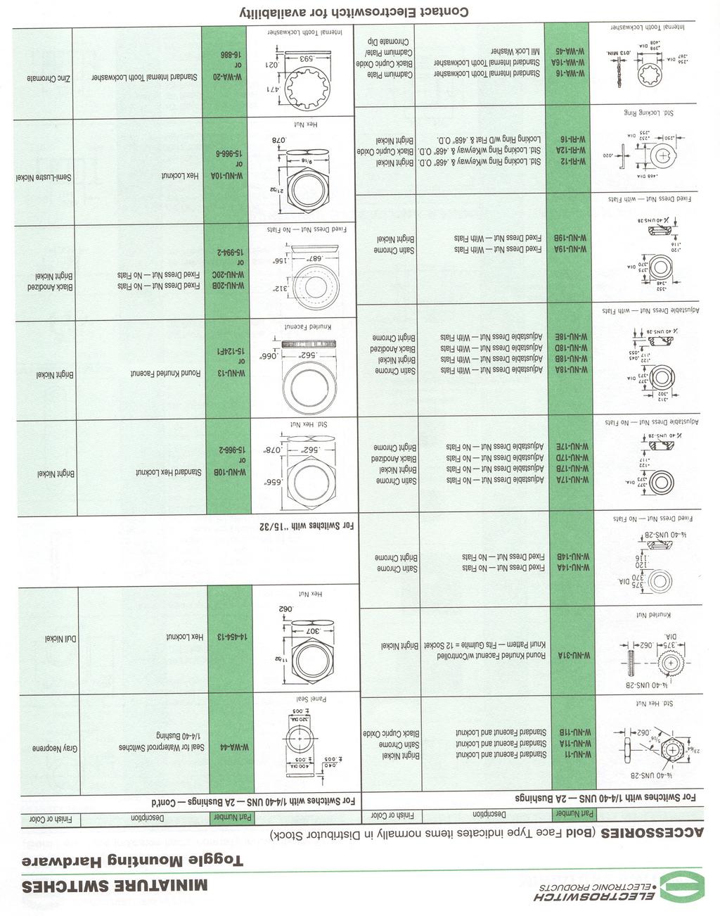
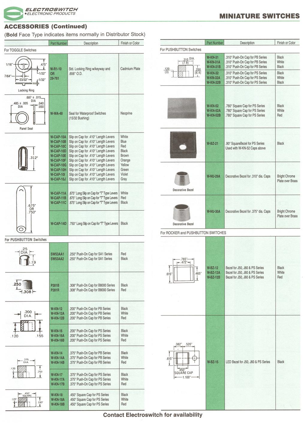
1 Sensitive Snap-Action Pushbutton Switches Solder and P.C. Terminals (Momentary Action) MINIATURE SWITCHES PS SERIES 5 AMP. (S.P.) 1 AMP (D.P.) 0.4 VA DIRECT PANEL MOUNT Basic P/N Terminal Type Poles Cap Size Cap Color Contact Material-Type PS 1 - Solder lug 1 - One 0 - No Cap 0 - No Cap B - Gold/Nickel/Brass 2 - Printed Circuit 2 - Two Dia. 1 - Black G - Gold/Nickel/ Terminals Dia. 2 - White Silver Sq. 3 - Ted Q - Coin Silver Dia Sq. Single pole circuit rated 5 amps, double pole circuit rated 1 amp. Ratings are 0.4 VA 28 BAC or DC Supplied with.90 square black bezel as Standard EXAMPLES: PS1-100Q = One-pole, S.L., 5 amp., No Cap, Coin Silver Contacts PS2-221B = Two-pole, PC,.4 VA,.375 Dia., Black Cap., Gold/Nickel/Brass Contacts NEW.780 SQUARE CAP AND BEZEL SPECIFICATIONS Contact Rating Letter codes G and Q (1 Pole) 5 amp 125 VAC (U.L. recognized, CSA certified) or 5 amp 28 VDC. (2 pole) 1 amp 125 VAC (U.L. recognized, CSA certified) or 1 amp 28 VDC. Letter codes B and G (1 and 2 Poles) 0.4 Volt-amps (VA) 28 V max. (AC or DC). Contact Resistance 50 milliohms maximum. Insulation Resistance 1,000 megohms minimum. Dielectric Strength 1,000 volts RMS minimum at sea level. Electrical Life 60,000 cycles minimum at full load-resistive. Maximum Allowable Installation Force on Plunger 10 pounds. Multi-pole contacts do not make and break simultaneously. W-NU-29A W-NU-30A DECORATIVE FACE NUTS (SEE NOTE UNDER MATERIALS) MATERIALS Case Diallyl Phthalate. Bushing Brass, nickel plated. Housing Stainless steel. Plunger Thermoplastic. Common Contact Refer to contact material table above. Center & End Contact Refer to contact material table above. Hardware (2) Hex nuts W-NU-11, brass nickel plated. (1) Internal tooth lockwasher W-WA-16, steel chromium plated. (1) Locking Ring W-RI-16, C.R.S. nickel plated. Decorative Face Nuts Brass, bright chrome plated. See Page 16 for complete dimensions. Description P/N Color W-KN-16 Black Small Cap.200 W-KN-16A White W-KN-16B Red W-KN-32 Black Medium Cap.310 W-KN-32A White W-KN-32B Red W-KN-17 Black Large Cap.375 W-KN-17A White W-KN-17B Red W-KN-18 Black Square Cap.450 W-KN-18A White W-KN-18B Red W-KN-52 Black.780 Square Cap W-KN-52A White W-KN-52B Red.90 Square Bezel Bezel W-BZ-21 Black Solder Lug Terminal Printed Circuit Terminal 4 Litho in U.S.A GG
2 PS SERIES 5 AMP. (S.P.) 0.4VA MINIATURE SWITCHES Sensitive Snap-Action Pushbutton Switches P.C. Terminals (Momentary Action) RIGHT ANGLE MOUNT IN P.C. BOARDS (HORIZONTAL) PS5 VIEW A-A PS6 VIEW A-A Basic P/N Terminal Type Poles Cap Size Cap Color Contact Material-Type 0 - No Cap 0 - No Cap B - Gold/Nickel/Brass PS 5 - Rt. Angle P.C. Mount Dia. 1 - Black G - Gold/Nickel/Silver 6 - Rt. Angle P.C. Mount 1 - One Dia. 2 - White Sq. 3 - Red Q - Coin Silver Dia. Rating is 5 amps 125 VAC or 28 VDC. Ratings are 0.4 VA 28 VAC or DC. ORDERING EXAMPLES: Gold/Nickel/ PS5-100G = (Rt. Angle P.C. mount 5 amp.) One-pole No Cap No Color Silver Contacts P S G PS6-121Q = (Rt. Angle P.C. mount 5 amp.) One-pole.375 Dia. Black Cap Coin Silver Contacts P S Q SPECIFICATIONS Contact Rating Letter codes G and Q 5 amp 125 VAC or 28 VDC. Letter codes B and G 0.4 volts-amps (VA) 28 VAC or DC. Contact Resistance 50 milliohms maximum. Insulation Resistance 1,000 megohms minimum. Dielectric Strength 1,000 volts RMS minimum at sea level. Electrical Life 60,000 cycles minimum at full load. Maximum Allowable Installation Force on Plunger 10 pounds. MATERIALS Case Diallyl Phthalate. Bushing Brass, nickel plated. Housing Stainless steel. Plunger Thermoplastic. Common Contact Refer to contact material table above. Center & End Contact Refer to contact material table above. Description P/N Color W-KN-16 Black Small Cap.200 W-KN-16A White W-KN-16B Red W-KN-32 Black Medium Cap.310 W-KN-32A White W-KN-32B Red W-KN-17 Black Large Cap.375 W-KN-17A White W-KN-17B Red W-KN-18 Black Square Cap.450 W-KN-18A White W-KN-18B Red Litho in U.S.A GG 5
3 Sensitive Snap-Action Pushbutton Switches P.C. Terminals (Momentary Action) MINIATURE SWITCHES PS SERIES 5 AMP. (S.P.) 1 AMP. (D.P.) 0.4VA RIGHT ANGLE P.C. MOUNT SWITCHES Basic P/N Terminal Type Poles Cap Size Cap Color Contact Material-Type 9 - Horizontal Right Angle 0 - No Cap 0 - No Cap B - Gold/Nickel/Brass PS 10 - Vertical Right Angle 1 - One Dia. 1 - Black G- Gold/Nickel/Silver (.100 Terminal Spacing) Dia. 2 - White 11 - Vertical Right Angle 0.4 VA 2 - Two Sq. 3 - Red Q - Coin Silver (.150 Terminal Spacing) Dia. Single pole circuit rated 5 amps, double pole circuit rated 1 amp. Ratings are 0.4 VA 28 VAC or DC. ORDERING EXAMPLES: Gold/Nickel/ PS9-100B = (PC mounted 0.4 VA) One-pole No Cap No Color Brass Contacts P S B PS10-221Q= (PC mounted 1 amp.) Two-pole.375 Dia. Black Cap Coin Silver Contacts P S Q SPECIFICATIONS Contact Rating Letter codes G and Q (1 Pole) 5 amp 125 VAC (U.L. recognized, CSA certified) or 5 amp 28 VDC. (2 pole) 1 amp 125 VAC (U.L. recognized, CSA certified) or 1 amp 28 VDC. Letter codes B and G (1 and 2 Poles) 0.4 Voltamps (VA) 28 V maximum (AC or DC). Contact Resistance 50 milliohms maximum. Insulation Resistance 1,000 megohms minimum. Dielectric Strength 1,000 volts RMS minimum at sea level. Electrical Life 60,000 cycles minimum at full loadresistive. Maximum Allowable Installation Force on Plunger 10 pounds. Multi-pole contacts do not make and break simultaneously. MATERIALS Case Diallyl Phthalate. Bushing Brass, nickel plated. Housing Stainless steel. Plunger Thermoplastic. Common Contact Refer to contact material table above. Center & End Contact Refer to contact material table above. Description P/N Color W-KN-16 Black Small Cap.200 W-KN-16A White W-KN-16B Red W-KN-32 Black Medium Cap.310 W-KN-32A White W-KN-32B Red W-KN-17 Black Large Cap.375 W-KN-17A White W-KN-17B Red W-KN-18 Black Square Cap.450 W-KN-18A White W-KN-18B Red Right Angle P.C. Terminal EPOXY SEAL STD. FOR THESE SERIES 6 Litho in U.S.A GG
4 PS SERIES 5 AMP. (S.P.) 1 AMP. (D.P.) 0.4VA MINIATURE SWITCHES Sensitive Snap-Action Pushbutton Switches P.C. Terminals (Momentary Action) RIGHT ANGLE P.C. MOUNT SWITCHES PS 9 1 Pole P.C. Mounting EPOXY SEALED P.C. TERMINALS ARE SUPPLIED AS STANDARD FOR THESE OPTIONS. PS 9 2 Pole P.C. Mounting EPOXY SEALED P.C. TERMINALS ARE SUPPLIED AS STANDARD FOR THESE OPTIONS. PS 10 1 Pole P.C. Mounting EPOXY SEALED P.C. TERMINALS ARE SUPPLIED AS STANDARD FOR THESE OPTIONS. PS 10 2 Pole P.C. Mounting EPOXY SEALED P.C. TERMINALS ARE SUPPLIED AS STANDARD FOR THESE OPTIONS. PS 11 1 Pole P.C. Mounting EPOXY SEALED P.C. TERMINALS ARE SUPPLIED AS STANDARD FOR THESE OPTIONS. PS 11 2 Pole P.C. Mounting EPOXY SEALED P.C. TERMINALS ARE SUPPLIED AS STANDARD FOR THESE OPTIONS. Litho in U.S.A GG 7
5 Sensitive Snap-Action Pushbutton Switches P.C. Terminals (Momentary Action) MINIATURE SWITCHES PS SERIES 5 AMP. (S.P.) 1 AMP. (D.P.) 0.4 VA VERTICAL P.C. MOUNT (.460 x.620 BRACKET) PS7 (LONG BUSHING) SP DP 1 Pole P.C. Mounting 2 Pole P.C. Mounting PS8 (SHORT BUSHING) SP DP Basic P/N Terminal Type Poles Cap Size Cap Color Contact Material-Type 0 - No Cap 0 - No Cap B - Gold/Nickel/Brass PS 7 - PC Mounted 1 - One Dia. 1 - Black G - Gold/Nickel/Silver 8 - PC Mounted 2 - Two Dia. 2 - White Sq. Q - Coin Silver Dia. Single pole circuit rated 5 amps, double pole circuit rated 1 amp. Ratings are 0.4 VA 28 VAC or DC. ORDERING EXAMPLES: Gold/Nickel/ PS7-100G = (PC mounted 5 amp.) One-pole No Cap No Color Silver Contacts P S G Gold/Nickel/ PS8-221B = (PC mounted 0.4 VA) Two-pole.375 Dia. Black Cap Brass Contacts P S B SPECIFICATIONS Contact Rating Letter codes G and Q (1 Pole) 5 amp 125 VAC (U.L. recognized, CSA certified) or 5 amp 28 VDC. (2 pole) 1 amp 125 VAC (U.L. recognized, CSA certified) or 1 amp 28 VDC. Letter codes B and G (1 and 2 Poles) 0.4 Voltamps (VA) 28 V maximum (AC or DC). Contact Resistance 50 milliohms maximum. Insulation Resistance 1,000 megohms minimum. Dielectric Strength 1,000 volts RMS minimum at sea level. Electrical Life 60,000 cycles minimum at full loadresistive. Maximum Allowable Installation Force on Plunger 10 pounds. Multi-pole contacts do not make and break simultaneously. MATERIALS Case Diallyl Phthalate. Bushing Brass, nickel plated. Housing Stainless steel. Plunger Thermoplastic. Common Contact Refer to contact material table above. Center & End Contact Refer to contact material table above. Description P/N Color W-KN-16 Black Small Cap.200 W-KN-16A White W-KN-16B Red W-KN-32 Black Medium Cap.310 W-KN-32A White W-KN-32B Red W-KN-17 Black Large Cap.375 W-KN-17A White W-KN-17B Red W-KN-18 Black Square Cap.450 W-KN-18A White W-KN-18B Red Printed Circuit Terminal EPOXY SEAL STD. FOR THIS SERIES 8 Litho in U.S.A GG
 PS71 (LONG BUSHING) SP DP 1 Pole P.C. Mounting 2 Pole P.C. Mounting PS81 (SHORT BUSHING) SP DP Basic P/N Terminal Type Poles Cap Size Cap Color Contact Material-Type 0 - No Cap 0 - No Cap B - Gold/Nickel/Brass 71 - PC Mounted 1 - One 1 -.")

6 MINIATURE SWITCHES Sensitive Snap-Action Pushbutton Switches P.C. Terminals (Momentary Action) PS SERIES 5 AMP. (S.P.) 1 AMP (D.P.) 0.4 VA VERTICAL P.C. MOUNT (.630 x.620 BRACKET) PS71 (LONG BUSHING) SP DP 1 Pole P.C. Mounting 2 Pole P.C. Mounting PS81 (SHORT BUSHING) SP DP Basic P/N Terminal Type Poles Cap Size Cap Color Contact Material-Type 0 - No Cap 0 - No Cap B - Gold/Nickel/Brass 71 - PC Mounted 1 - One Dia. 1 - Black PS81 - PC Mounted 2 - Two Dia. 2 - White G - Gold/Nickel/Silver Sq. 3 - Red Q - Coin Silver Dia. Single pole circuit rated 5 amps, double pole circuit rated 1 amp. Ratings are 0.4 VA 28 VAC or DC. ORDERING EXAMPLES: Gold/Nickel/ PS71-100B= (PC mounted 0.4 VA) One-pole No Cap No Color Brass Contacts P S B PS81-221Q= (PC mounted 1 amp.) Two-pole.375 Dia. Black Cap Coin Silver Contacts P S Q SPECIFICATIONS Contact Rating Letter codes G and Q (1 Pole) 5 amp 125 VAC (U.L. recognized, CSA certified) or 5 amp 28 VDC. (2 pole) 1 amp 125 VAC (U.L. recognized, CSA certified) or 1 amp 28 VDC. Letter codes B and G (1 and 2 Poles) 0.4 Voltamps (VA) 28 V maximum (AC or DC). Contact Resistance 50 milliohms maximum. Insulation Resistance 1,000 megohms minimum. Dielectric Strength 1,000 volts RMS minimum at sea level. Electrical Life 60,000 cycles minimum at full loadresistive. Maximum Allowable Installation Force on Plunger 10 pounds. Multi-pole contacts do not make and break simultaneously. MATERIALS Case Diallyl Phthalate. Bushing Brass, nickel plated. Housing Stainless steel. Plunger Thermoplastic. Common Contact Refer to contact material table above. Center & End Contact Refer to contact material table above. Description P/N Color W-KN-16 Black Small Cap.200 W-KN-16A White W-KN-16B Red W-KN-32 Black Medium Cap.310 W-KN-32A White W-KN-32B Red W-KN-17 Black Large Cap.375 W-KN-17A White W-KN-17B Red W-KN-18 Black Square Cap.450 W-KN-18A White W-KN-18B Red Printed Circuit Terminal EPOXY SEAL STD. FOR THIS SERIES Litho in U.S.A GG 9
7 Sensitive Snap-Action Pushbutton Switches P.C. Terminals (Momentary Action) MINIATURE SWITCHES PS SERIES 5 AMP. (S.P.) 1 AMP. (D.P.) 0.4 VA VERTICAL P.C. MOUNT (.460 x.750 BRACKET) PS72 (LONG BUSHING) SP DP 1 Pole P.C. Mounting 2 Pole P.C. Mounting PS82 (SHORT BUSHING) SP DP Basic P/N Terminal Type Poles Cap Size Cap Color Contact Material-Type 0 - No Cap 0 - No Cap B - Gold/Nickel/Brass PS 72 - PC Mounted 1- One Dia. 1- Black G - Gold/Nickel/Silver 82 - PC Mounted 2 - Two Dia. 2 - White Sq. 3 - Red Q - Coin Silver Dia. Single pole circuit rated 5 amps, double pole circuit rated 1 amp. Ratings are 0.4 VA 28 VAC or DC. ORDERING EXAMPLES: PS72-100Q= (PC mounted 5 amp.) One-pole No Cap No Color Coin Silver Contacts P S Q Gold/Nickel/ PS82-221B= (PC mounted 0.4 VA) Two-pole.375 Dia. Black Cap Brass Contacts P S B SPECIFICATIONS Contact Rating Letter codes G and Q (1 Pole) 5 amp 125 VAC (U.L. recognized, CSA certified) or 5 amp 28 VDC. (2 pole) 1 amp 125 VAC (U.L. recognized, CSA certified) or 1 amp 28 VDC. Letter codes B and G (1 and 2 Poles) 0.4 Voltamps (VA) 28 V maximum (AC or DC). Contact Resistance 50 milliohms maximum. Insulation Resistance 1,000 megohms minimum. Dielectric Strength 1,000 volts RMS minimum at sea level. Electrical Life 60,000 cycles minimum at full loadresistive. Maximum Allowable Installation Force on Plunger 10 pounds. Multi-pole contacts do not make and break simultaneously. MATERIALS Case Diallyl Phthalate. Bushing Brass, nickel plated. Housing Stainless steel. Plunger Thermoplastic. Common Contact Refer to contact material table above. Center & End Contact Refer to contact material table above. Description P/N Color W-KN-16 Black Small Cap.200 W-KN-16A White W-KN-16B Red W-KN-32 Black Medium Cap.310 W-KN-32A White W-KN-32B Red W-KN-17 Black Large Cap.375 W-KN-17A White W-KN-17B Red W-KN-18 Black Square Cap.450 W-KN-18A White W-KN-18B Red Printed Circuit Terminal EPOXY SEAL STD. FOR THIS SERIES 10 Litho in U.S.A GG
 PS73 (LONG BUSHING) SP DP 1 Pole P.C. Mounting 2 Pole P.C. Mounting PS83 (SHORT BUSHING) SP DP Basic P/N Terminal Type Poles Cap Size Cap Color Contact Material-Type 0 - No Cap 0 - No Cap B - Gold/Nickel/Brass PS 73 - PC Mounted 1 - One 1 -.")

8 MINIATURE SWITCHES Sensitive Snap-Action Pushbutton Switches P.C. Terminals (Momentary Action) PS SERIES 5 AMP. (S.P.) 1 AMP (D.P.) 0.4 VA VERTICAL P.C. MOUNT (.630 x.750 BRACKET) PS73 (LONG BUSHING) SP DP 1 Pole P.C. Mounting 2 Pole P.C. Mounting PS83 (SHORT BUSHING) SP DP Basic P/N Terminal Type Poles Cap Size Cap Color Contact Material-Type 0 - No Cap 0 - No Cap B - Gold/Nickel/Brass PS 73 - PC Mounted 1 - One Dia. 1 - Black G - Gold/Nickel/Silver 83 - PC Mounted 2 - Two Dia. 2 - White Sq. 3 - Red Q - Coin Silver Dia. Single pole circuit rated 5 amps, double pole circuit rated 1 amp. Ratings are 0.4 VA 28 VAC or DC. ORDERING EXAMPLES: Gold/Nickel/ PS73-100G= (PC mounted 5 amp.) One-pole No Cap No Color Silver Contacts P S G Gold/Nickel/ PS83-221B= (PC mounted 0.4 VA) Two-pole.375 Dia. Black Cap Brass Contacts P S B SPECIFICATIONS Contact Rating Letter codes G and Q (1 Pole) 5 amp 125 VAC (U.L. recognized, CSA certified) or 5 amp 28 VDC. (2 pole) 1 amp 125 VAC (U.L. recognized, CSA certified) or 1 amp 28 VDC. Letter codes B and G (1 and 2 Poles) 0.4 Voltamps (VA) 28 V maximum (AC or DC). Contact Resistance 50 milliohms maximum. Insulation Resistance 1,000 megohms minimum. Dielectric Strength 1,000 volts RMS minimum at sea level. Electrical Life 60,000 cycles minimum at full loadresistive. Maximum Allowable Installation Force on Plunger 10 pounds. Multi-pole contacts do not make and break simultaneously. MATERIALS Case Diallyl Phthalate. Bushing Brass, nickel plated. Housing Stainless steel. Plunger Thermoplastic. Common Contact Refer to contact material table above. Center & End Contact Refer to contact material table above. Description P/N Color W-KN-16 Black Small Cap.200 W-KN-16A White W-KN-16B Red W-KN-32 Black Medium Cap.310 W-KN-32A White W-KN-32B Red W-KN-17 Black Large Cap.375 W-KN-17A White W-KN-17B Red W-KN-18 Black Square Cap.450 W-KN-18A White W-KN-18B Red Printed Circuit Terminal EPOXY SEAL STD. FOR THIS SERIES Litho in U.S.A GG 11


9 Sensitive Snap-Action Pushbutton Switches Solder and P.C. Terminals (Momentary Action) MINIATURE SWITCHES PS SERIES 5 AMP. (S.P.) 1 AMP (D.P.) 0.4 VA SNAP-IN MOUNT PS14 SHOWN w/raised CAP PS15 SHOWN w/flush CAP Optional Features Cap Configuration Basic P/N Terminal-Rating Poles Cap Size Cap Color Bezel Color & Type Contact Material-Type PS 14 - Raised Cap 1 - One 0 - No Cap 0 - No Cap 1 - White B - Gold/Nickel/Brass Solder Lug 2 - Two Sq. 1 - White 2 - Black 15 - Flush Cap 2 -Black 3 -Red Solder Lug 3 - Red 4 - Black or LED 16 - Raised Cap G - Gold/Nickel/Silver PC Terminals Q - Coin Silver 17 - Flush Cap PC Terminals Single pole circuit rated 5 amps, double pole circuit rated 1 amp. Ratings are 0.4 VA 28 BAC or DC. Flush cap is flush to bezel, not to mounting bracket. SPECIFICATIONS Contact Rating Letter codes G and Q (1 Pole) 5 amp 125 VAC (U.L. recognized, CSA certified) or 5 amp 28 VDC. (2 pole) 1 amp 125 VAC (U.L. recognized, CSA certified) or 1 amp 28 VDC. Letter codes B and G (1 and 2 Poles) 0.4 Voltamps (VA) 28 V maximum (AC or DC). Contact Resistance 50 milliohms maximum. Insulation Resistance 1,000 megohms minimum. Dielectric Strength 1,000 volts RMS minimum at sea level. Electrical Life 60,000 cycles minimum at full loadresistive. Maximum Allowable Installation Force on Plunger 10 pounds. Multi-pole contacts do not make and break simultaneously. LED Not Included EXAMPLES: PS14-100Q = Raised Cap, Solder Lug Terminals, 5 Amp, Single Pole, No Cap, Coin Silver Contacts PS B = Raised Cap, Solder Lug Terminals, 0.4 VA Rating, Single Pole,.450 Square Red Cap, Black Bezel for LED, Gold/Brass Contact Material MATERIALS Case Diallyl Phthalate. Bushing Brass, nickel plated. Housing Stainless steel. Plunger Thermoplastic. Pushbutton Cap Molded nylon. Bezel Molded nylon. Common Contact Refer to contact material table above. Center & End Contact Refer to contact material table above. Solder Lug Terminal PC Terminal 12 Litho in U.S.A GG

10 MINIATURE SWITCHES Sensitive Snap-Action Pushbutton Switches Solder and P.C. Terminals (Momentary Action) APPROXIMATE DIMENSIONS (For Optional Bezel Types Shown on Page 12) OPTIONAL BEZEL TYPE 1, 2, 3 (SEE TABLE) PS14 Shown w/raised Cap OPTIONAL BEZEL TYPE 1, 2, 3 (SEE TABLE) PS15 Shown w/flush Cap Catalog No. W-BZ-12 W-BZ-12A W-BZ-12B Color Black White Red OPTIONAL BEZEL TYPE 4 FOR LED PS14 Shown w/raised Cap Catalog No. W-BZ-12 W-BZ-12A W-BZ-12B Color Black White Red OPTIONAL BEZEL TYPE 4 FOR LED PS17 Shown w/flush Cap SWITCHES SUPPLIED WITHOUT LED LAMPS. SWITCHES SUPPLIED WITHOUT LED LAMPS. Catalog No. W-BZ-15 Color Black Catalog No. W-BZ-15 Color Black OPTIONAL MOUNTING CLIP (For Use With PS14 Thru PS17 Series Only) For thick plastic panel mount applications ( thick) For availability consult Electroswitch. Litho in U.S.A GG 13
 Following the table from left to right, the designer is able to specify To determine a part number select the options desired and fill in the options wanted.")
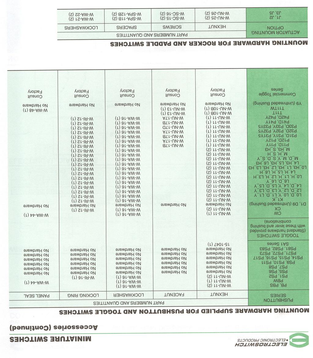
11 MINIATURE SWITCHES Standard Ordering Table Pushbutton Switches Panelmount Maintained and Momentary Action (SPDT) HOW TO ORDER YOUR DESIGN (Bold Face Type indicates items normally in Distributor Stock) Following the table from left to right, the designer is able to specify To determine a part number select the options desired and fill in the options wanted. The options are described and illustrated on the boxes in the selection guides illustrated below. pages Pushbutton Switch Selection Guide Pushbutton Cap Cap Terminal Contact Switch Series Circuit Size Color Type Material Other PB Base P/N Circuit Cap Size PBS Plunger Seal PBW Plunger & Panel Seal -123 ON-NONE-ON Push to make contact and Push again to reverse action -126 ON-NONE-ON* Normally Open or Normally Closed. (For NC circuit use Terminal 2 & 1, for NO. 2 & 3, for NC and NO. 1, 2 & 3) 0 No Cap Dia Dia Dia. Suffix Numbers & Letters Add to Base Catalog Number Cap Color Terminal Options Contact Material-Type Other Options 0 No Cap Z Solder Lugs B Gold/Nickel/ Epoxy Sealed 1 Black C Printed Circuit Z3 Quick Connect Brass G Gold/Nickel/ Terminals 2 White W.750 Wirewrap W1.964 Wirewrap Silver Q Coin Silver 3 Red W3.425 Wirewrap W Wirewrap K L A Right Angle P.C. M AV Vertical P.C..100 Spacing AV2 Vertical P.C..150 Spacing *Momentary Contact Ratings are 0.4 VA-28 VAC or DC. Same as B, G and Q respectively except terminals brass with tin nickel alloy over Epoxy seal standard on all terminal options. nickel plate. Consult factory for availability EXAMPLES: PB-12331ZQ = Maintained (Push-Push) circuit,.375 Black Cap, Solder Lug Terminals, Silver Contacts, 6 Amp Rating and Epoxy Sealed Terminals PBW-12613CB = Plunger & Panel Seal, Momentary circuit,.200 Red Cap epoxy sealed Printed Circuit Terminals and 50 Millionths Gold over Brass contacts. APPROXIMATE DIMENSIONS PB w /.375 CAP MAINTAINED ACTION PBS w /.310 CAP PBW w /.200 CAP MOMENTARY ACTION SPECIFICATIONS Contact Rating Letter codes G and Q 6 amp at 125 VAC, 3 amp at 250 VAC (U.L. recognized, CSA certified) or 6 amp at 28 VDC resistive. Letter codes B and G 0.5. volt-amp (VA) 28 V maximum (AC or DC). Life Under Load (Resistive) Alternate Action Suffix 123; 100,000 make-and break cycles Momentary Action Suffix 126; 60,000 make-and-break cycles Initial Contact Resistance 10 milliohms max. 3 VDC, 100 ma for both silver and gold plated contacts. Insulation Resistance 1,000 MBG. Dielectric Strength 1,000 volts rms at sea level. Bushing Strength 12 pound-inches without physical damage to switch Operating Force 1.5 lb lb. Pretravel.043 Max..106 Max. Overtravel.009 Min..008 Min. MATERIALS Base (body) Diallyl Phthalate. Bushing Brass, nickel plated. Clamp (frame) Stainless steel. Switching Contacts and Rockers Letter Code B gold/nickel/brass Letter Code G gold/nickel/silver Letter Code Q Coin silver Center Terminal Letter Codes B, G Gold flash/nickel/brass Letter Code Q Silver plated brass. Hardware PB and PBS Series (2) W-NU-11 hex nuts (1) W-WA-16 internal tooth lockwasher PBW Series (1) W-NU-11 hex nut (1) W-WA-16 internal tooth lockwasher (1) W-WA-44 neoprene panel seal 14 Litho in U.S.A GG
12 MINIATURE SWITCHES Pushbutton Switches Panelmount Maintained and Momentary Action (SPDT) Termination Options C Printed Circuit W Wire-Wrap W1 Wire-Wrap W3 Wire-Wrap W4 Wire-Wrap Z Standard Z3 Quick Connect Mating Receptacle from AMP SPECIAL IND., P.O. Box 984, Paoli, Pa Amp P/N single piece series, strip from NOTE: Wire-Wrap is a registered trademark of the Gardner-Denver Company. APPROXIMATE DIMENSIONS PB, PBS, PBW SWITCHES w/ A TYPE RIGHT ANGLE P.C. TERMINALS DIM. PB-123 PB-126 A B P.C. Mounting EPOXY SEALED P.C. TERMINALS ARE SUPPLIED AS STANDARD FOR THESE OPTIONS PB, PBS, PBW SWITCHES w/ AV (.100 TERMINAL SPACING) OR AV2 (.150 TERMINAL SPACING) TYPE VERTICAL P.C. TERMINALS AV2 DIM. PB-123 PB-126 A B AV P.C. Mounting EPOXY SEALED P.C. TERMINALS ARE SUPPLIED AS STANDARD FOR THESE OPTIONS Litho in U.S.A GG 15

13 MINIATURE SWITCHES Pushbutton Switches Panelmount Maintained and Momentary Action (SPDT) PUSHBUTTON CAP STYLES FOR PB SERIES SWITCHES ON PAGE 14 PART NUMBER COLOR PART NUMBER COLOR PART NUMBER COLOR W-KN-12 W-KN-12A BLACK WHITE W-KN-31 W-KN-31A BLACK WHITE W-KN-14 W-KN-14A BLACK WHITE W-KN-12B W-KN-12C RED GREEN W-KN-31B W-KN-31C RED GREEN W-KN-14B W-KN-14C RED GREEN W-KN-12D W-KN-12E BLUE DK. GRAY W-KN-31D W-KN-31E BLUE DK. GRAY W-KN-14D W-KN-14E BLUE DK. GRAY W-KN-12F W-KN-12G YELLOW LT. GRAY W-KN-31F W-KN-31G YELLOW LT. GRAY W-KN-14F W-KN-14G YELLOW LT. GRAY Black, white, red are standard. Contact Electroswitch for availability on other colors shown. DECORATIVE FACENUTS FOR PB SERIES AND PS SERIES PART NUMBER W-NU-29A (For.310 Dia. Caps) PART NUMBER W-NU-30A (For.375 Dia. Caps) Part No. W-NU-29A Assembled to PB Series Switch. Part No. W-NU-30A Assembled to PS Series Switch. (See page 4) Finish: Bright chrome plate over brass Finish: Bright chrome plate over brass 16 Litho in U.S.A GG
14 MINIATURE SWITCHES Sub Miniature Pushbutton Switches for Printed Circuit Boards Wave Solderable Series B8000 PCB Pushbutton Switches SPECIFICATIONS Mechanical life 500,000 operations minimum Contact resistance 25 milliohms maximum Dielectric strength 1000 VAC rms Ambient temperature range -20 C to +70 C Weight 0.06 ounces (1.7 grams) Electrical life 100,000 operations minimum. SELECTION TABLES (Bold Face Type indicates items normally in Distributor Stock) Note: Optional Snap-On button must be ordered separately B8500/B8600 For Latch-Down, depress plunger and rotate 30 clockwise. Poles & Throw 2 Circ. Operation Momentary or Latch Down Momentary or Latch Down Momentary Catalog No. By Terminal Type Right Angle P.C. Stand P.C. Mount Up Mount (5.6 mm) (4.1 mm) (3.1 mm) B8103 B8500 B8600 APPROXIMATE DIMENSIONS B8103, B8500 and B8600 Series Schematic Pushbutton PCB Switches OPTIONAL BUTTON CAPS Button Cap Color Black Red CURRENT RATINGS Nominal Rating, Amperes Catalog Number P281B P281R 6 VDC 12 VDC 28 VDC 125 VDC NOTE: For special.5 VA max. 28 VAC or DC contact Electroswitch. High Contact pressure gives low contact resistance Crossed Wire contact system eliminates bounce Gold over nickel over silver over copper Gold-plated shorting bar and terminals provide over 500,000 cycles low level current/ voltage operation Drain holes permit complete flux washdown terminal length order B8103 TYPE P281 SNAP-ON BUTTON (Optional) SPECIFICATIONS Resistive rating.75 amperes resistive at 125 VAC normally open;.50 amperes resistive at 125 VAC normally closed; also rated 1.0 ampere normally open for 15,000 operations and.75 amperes normally closed for 10,000 operations. For 28 VDC rating 1.5 amperes normally open for 10,000 operations and 1.0 ampere normally closed for 10,000 operations. Dry circuit rated 10 milliamperes at 30 mvdc. APPROXIMATE DIMENSIONS ACTUAL SIZE Ultra-Miniature Pushbutton Switches AC and DC Round Base OPTIONAL BUTTON CAP MUST BE ORDERED SEPARATELY Pretravel.015 minimum/.050 maximum Overtravel.030 minimum Operating force 8 oz. maximum Electrical life 50,000 operations minimum Mechanical life 50,000 operations minimum Materials contacts and terminals are gold plated copper Mounting hardware One #8-40 nut supplied unassembled SELECTION TABLE Circuit Plunger Catalog Color Number N.O. Red SA1RV20 N.O. Black SA1BV20 N.C. Black SA1BW20 N.C. Red SA1RW20 OPTIONAL BUTTON CAPS Button Cap Catalog Color Number Description ` Red SW53AA1.250 Slip on cap for SA1 series Black SW53AA2.250 Slip on cap for SA1 series CAUTION MANUAL SWITCHES ARE AFFECTED BY HEAT, CLEANING SOLVENTS AND FLUX. EXTREME CARE SHOULD BE EXERCISED DURING HAND SOLDERING AND WAVE SOLDERING TO PREVENT SWITCH CONTAMINATION. 17
15 Ordering Table Washable Rocker & Paddle Switches MINIATURE SWITCHES Designed to be wave soldered along with other Printed Circuit Board Components and withstand associated cleaning processes. HOW TO ORDER YOUR DESIGN (Bold Face Type indicates items normally in Distributor Stock) Following the table from left to right, the designer is able to specify To determine a part number select the options desired and fill in the options wanted. The options are described and illustrated on the boxes in the selection guides illustrated below. the following pages. Washable Rocker/Paddle Switch Selection Guide Poles Switch and Terminal Contact Actuator Series Throw Circuit Actuator Type Material Color Series Poles and Throw Circuits Actuator Options Terminal Options Contact Material Actuator Color Type Code No. Code Description Code Type Code Type Code Type Code Type Code Rocker Paddle WR WP SPDT DPOT 1 2 ON ON ON ON* ON ON ON ON* OFF NONE NONE OFF OFF ON ON ON POS. "C" ON ON ON* ON* ON* ON ON* ON* Rocker (Screw Mount) Paddle (Screw Mount) Rocker Actuator Paddle Actuator Rocker Actuator Paddle Actuator *Momentary Contact. 2 Pole Only. Contact Electroswitch for availability. Refer to page 59 for circuit diagram. Same as B, G, and Q respectively except terminals brass with tine nickel alloy over nickel plate. Consult factory for availability. Available with C, Z, Z3, W-W4 termination. Available with A, AV2, V3, termination J1 J2 J71 J72 J76 J77 Right Angle PC Vertical PC.150 Spacing PC Terminals PC & Support.750 Wire Wrap.964 Wire Wrap.425 Wire Wrap Wire Wrap Solder Lug Quick Connect A AV2 C V3 W W1 W3 W4 Z Z3 Gold/Brass Gold/Silver Coin Silver B G Q K L M White Black Other 1 2 EXAMPLES: WR123J71AQ2 WP227J2CG2 = SPDT rocker switch with an ON-NONE-ON circuit, J71 style rocker actuator (black), right angle P.C. terminals with coin silver contacts. = DPDT paddle switch with an ON*-OFF-ON* circuit, J2 style paddle actuator (black), screw-in direct panel mounting frame, P.C. terminals with gold/silver contacts. SPECIFICATIONS: Contact Ratings Letter codes G and Q 6 amp at 125 VAC, VAC (U.L. recognized, CSA certified) or 6 amp at 28 VDC resistive. Letter codes B and G 0.5. volt-amp (VA) 28 V maximum (AC or DC). Life Under Load 60,000 make-and-break cycles resistive load only. Initial Contact Resistance 10 milliohms maximum 3 VDC, 100 ma for both silver and gold plated contacts. Insulation Resistance 1,000 megohms, min. Dielectric Strength 1,000 volts rms at sea level. Operating Temperature -30 degrees C to 85 degrees C. MATERIALS: Base & Bushing Thermoplastic high temperature (UL 94V-O). Rocker/Paddle Molded nylon. Mounting Bracket Molded nylon. Support Brackets Brass or steel tin plated. Switching Contacts and Rockers Letter Code B gold/nickel/brass Letter Code G gold/nickel/silver Letter Code Q Coin silver Center Terminal Letter Codes B & G Gold flash/nickel/brass Letter Code Q Silver plated brass. Hardware Two mounting screws, two nuts, two spacers for.094" thick panel, and two lockwashers are supplied standard on screw mounted switches. 32 Litho in U.S.A GG

16 MINIATURE SWITCHES Washable Rocker & Paddle Switches Specifications APPROXIMATE BASE DIMENSIONS ACTUATOR/MOUNTING OPTIONS J1 Screw Mount Rocker J2 Screw Mount Paddle J71 J72 J76 J77 Litho in U.S.A GG 33
17 Washable Rocker & Paddle Switches MINIATURE SWITCHES TERMINATION OPTIONS C Printed Circuit W Wire-Wrap W1 Wire-Wrap W3 Wire-Wrap W4 Wire-Wrap Z Standard Z3 Quick Connect Mating Receptacle from AMP SPECIAL IND., P.O. Box 984, Paoli, Pa Amp P/N single piece series, strip from NOTE: Wire-Wrap is a registered trademark of the Gardner-Denver Company. TERMINATION & MOUNTING OPTIONS A P.C. MOUNTING A P.C. MOUNTING 34 Litho in U.S.A GG
18 MINIATURE SWITCHES Washable Rocker & Paddle Switches TERMINATION & MOUNTING OPTIONS Contd. AV2 P.C. MOUNTING AV2 P.C. MOUNTING V3 P.C. MOUNTING V3 P.C. MOUNTING Litho in U.S.A GG 35
19
20 Ordering Table Standard Toggle Switches HOW TO ORDER YOUR DESIGN (Bold Face Type indicates items normally in Distributor Stock) Following the table from left to right, the designer is able to specify the options wanted. The options are described and illustrated on pages Refer to page 57 for mounting hardware. Toggle Switch Selection Guide MINIATURE SWITCHES Toggle Poles Switch and Lever Lever Bushing Terminal Contact Series Throw Circuit Options Finish Options Type Material Other + To determine a part number select the options desired and fill in the boxes in the selection guides illustrated below Poles and Throw Circuits Lever Options and Finishes Bushing Options Terminal Options Contact Material Other Option Series No. Code Code Type Code Finish Code Type Code Type Code Type Code Type Code A SPDT DPDT 3PDT 4PDT POS. "C" ON OFF ON 21 ON NONE ON 23 ON NONE ON* 26 ON* OFF ON* 27 ON OFF ON* 31 ON ON ON 32 ON ON ON* 33 NONE ON ON* 34 ON* ON ON* 35 NONE ON ON 53 Lever Lock K Bushing Only.840 Bat.640 Bat.550 Bat Long Mod Cap Short Mod Cap.200 Bat.840 Flat.450 Flat.250 Flat.410 Bat.468 Large.687 Large K1 L0 L1 L2 L3 L4 M P1 P3 P4 S T1 T Bright Chrome Stain Chrome Black Black Nylon Red Nylon White Nylon Splashproof Lever & Bushing Seal Splashproof Lever Seal Only.280 Threaded.280 Smooth.350 Flatted With Shoulder.350 Keyway With Shoulder Locking K1 Lever Only 15/32 Dia. Splashproof Lever 15/32 & Panel Seal 15/32 Splashproof Lever Seal Only.350 Threaded.437 Threaded (With P3 Only).350 Smooth CW CX D D9 H H3 K T TW TX Y Y5 Y9 Right Angle PC Vertical PC.100 Spacing Vertical PC.150 Spacing Printed Circuit Terminals Right Angle Same Throw Right Angle Opposite Throw PC & Support PC & Support PC & Support PC & Support.750 Wire Wrap.964 Wire Wrap.425 Wire Wrap Wire Wrap Solder Lugs Quick Connect A AV AV2 C R R2 V30 V40 V60 V70 W W1 W3 W4 Z Z3 Gold/Nickel/Brass Gold/Nickel/Silver Coin Silver B G Q K L M Epoxy Sealed Terminals Anti-Rotation Anti-Jam Bushing P *Momentary Contact Available on S, M and P3 only. Add.070 to lever length when using these bushings. Available with S, M, L0, L1, L2, L3, L4 lever options. Consult factory for availability. Standard on P1, P3, P4 and K1 lever options. Available on all other levers except T & T1. These circuits are NOT available with the following 3 and 4 pole options: A, AV, AV2, V30, V40, V60 and V70. 1 and 2 pole only. Epoxy seal standard on all terminal options. Available only with L3 and L4 levers. Available in 1 pole only. See page 58 for construction detail, wiring and electrical diagrams. 1, 2 and 3 pole only. Available on T or T1 lever options only. Available on T, TW, and TX bushing options. (Bright chrome only.) Not available on K1 lever. Same as B, G and Q respectively except terminals brass with tin nickel alloy over nickel plate. Consult plant for availability. EXAMPLES: A232L01YW1B = DPDT toggle switch with an ON-ON-ON circuit,.840" long lever in a bright chrome finish,.350 threaded bushing,.964" long wire wrap terminals, gold/brass contacts and epoxy sealed terminals. SPECIFICATIONS: Contact Ratings Letter codes G and Q 6 amp at 125 VAC, VAC (U.L. recognized, CSA certified) or 6 amp at 28 VDC resistive. Letter codes B and G 0.5. volt-amp (VA) 28 V maximum (AC or DC). Life Under Load 60,000 make-and-break cycles resistive load only. Initial Contact Resistance 10 milliohms maximum 3 VDC, 100 ma for both silver and gold plated contacts. Insulation Resistance 1 & 2 pole 1,000 megohms, min. 3 & 4 pole 1,000 megohms, min. Dielectric Strength 1,000 volts rms at sea level. Bushing Strength 12 pound-inches without physical damage to switch. Weight (including hardware) SP 0.19 oz.; DP 0.23 oz.; 3-pole 0.28 oz.; 4-pole 0.32 oz. MATERIALS: Base (body) 1- and 2-pole Diallyl Phthalate (DAP). 3- and 4-pole high strength phenolic. Lever (toggle) Brass, chrome plated. Flat Lever Brass, satin chrome finish. Locking lever cap Anodized aluminum. Bushing Brass, nickel plated. Clamp (frame) Stainless steel. Support brackets Steel, tin plated. Switching Contacts and Rockers Letter Code B gold/nickel/brass Letter Code G gold/nickel/silver Letter Code Q Coin silver Center Terminal Letter Codes B, G Gold flash/nickel/brass Letter Code Q Silver plated brass. Hardware See page Litho in U.S.A GG
21 MINIATURE SWITCHES Toggle Switches Base Dimensions and Lever Options APPROXIMATE BASE DIMENSIONS THREE POLE FOUR POLE TOGGLE LEVER OPTIONS K1 Locking Lever L0 Long (.840") L1 Long (.640") L2 Long (.550") L3 Plastic (.840") L4 Plastic (.571") Litho in U.S.A GG 39
22 Toggle Lever Options Contd. M Short (.200") P1 Flatted (.840") P3 Flatted (.448") MINIATURE SWITCHES P4 Flatted (.250") S Std. Bat (.410") T Large Toggle T1 Large Toggle BUSHING OPTIONS CW Splashproof Sealed Lever and Panel Seal D Threaded D9 Smooth CW = Flatted bushing (No Keyway) H High Torque Flatted with Shoulder H3 High Torque P Anti-Rotation TW Splashproof Sealed Lever and Panel Seal OX Y Y9 Threaded with Lever Seal Threaded Smooth (No Keyway) Y5 Long Bushing (.437") K Refer to K1 lever drawing for dimensions. T & TX Refer to T or T1 lever drawing for dimensions. Note: For hardware refer to pages Litho in U.S.A GG
23 MINIATURE SWITCHES Termination Options C Printed W Wire-Wrap W1 Wire-Wrap W3 Wire-Wrap W4 Wire-Wrap Z STANDARD Z3 Quick CIRCUIT CONNECT NOTE: Wire-Wrap is a registered trademark of the Gardner-Denver Company. Mating Receptacle from AMP SPECIAL IND., P.O. Box 984, Paoli, Pa Amp P/N single piece series, strip from TERMINATION/MOUNTING OPTIONS A One Pole A Right Angle P.C. Terminal EPOXY SEAL STD. FOR THIS OPTION Two Pole A Three Pole R One Pole R2 Contacts Make on Opposite Side Toggle Thrown One Pole Contacts Make on Opposite Side Toggle Thrown Litho in U.S.A GG 41
24 Termination/Mounting Options MINIATURE SWITCHES AV1 AV2 w/.100" terminal spacing w/.150" terminal spacing (pictured below) Epoxy sealed P.C. terminals are supplied as standard for these options. AV1 w/.100" terminal spacing AV2 w/.150" terminal spacing (pictured below) Epoxy sealed P.C. terminals are supplied as standard for these options. AV w/.100" terminal spacing AV2 w/.150" terminal spacing (pictured below) THREE POLE Epoxy sealed P.C. terminals are supplied as standard for these options. AV w/.100" terminal spacing AV2 w/.150" terminal spacing (pictured below) FOUR POLE Epoxy sealed P.C. terminals are supplied as standard for these options. 42 Litho in U.S.A GG

25 MINIATURE SWITCHES Termination/Mounting Options V30 1 Pole P.C. Mounting V40 2 Pole P.C. Mounting EPOXY SEALED P.C. TERMINALS ARE SUPPLIED AS STANDARD FOR THESE OPTIONS 1 Pole P.C. Mounting V60 2 Pole P.C. Mounting EPOXY SEALED P.C. TERMINALS ARE SUPPLIED AS STANDARD FOR THESE OPTIONS 1 Pole P.C. Mounting V70 2 Pole P.C. Mounting EPOXY SEALED P.C. TERMINALS ARE SUPPLIED AS STANDARD FOR THESE OPTIONS 1 Pole P.C. Mounting 2 Pole P.C. Mounting EPOXY SEALED P.C. TERMINALS ARE SUPPLIED AS STANDARD FOR THESE OPTIONS Litho in U.S.A GG 43
26 Ordering Table Washable Toggle Switches MINIATURE SWITCHES Designed to be wave soldered along with other Printed Circuit Board Components and withstand associated cleaning processes. HOW TO ORDER YOUR DESIGN (Bold Face Type indicates items normally in Distributor Stock) Following the table from left to right, the designer is able to specify the options wanted. The options are described and illustrated on The following pages. WashableToggle Switch Selection Guide To determine a part number select the options desired and fill in the boxes in the selection guides illustrated below. Poles Toggle and Lever Lever Bushing Terminal Contact Series Throw Circuit Options Finish Options Type Material Series Poles and Throw Circuits Lever Options and Finishes Bushing Options Terminal Options Contact Material Keyway Type Code No. Code Code Type Code Finish Code Type Code Type Code Type Code Toggle WT SPDT DPDT 1 2 POS. "C" ON OFF ON ON NONE ON ON NONE ON* ON* OFF ON* ON OFF ON* ON ON ON ON ON ON* ON* ON ON* BAT..740 BAT..650 BAT. Long Mod Cap Short Mod Cap.510 BAT..300 BAT. L0 L1 L2 L3 L4 S M Bright Chrome Black Black Nylon Red Nylon White Nylon Smooth.280 Smooth.350 Threaded.350 Smooth D1 D9 Y Y9 Right Angle PC Vertical PC.150 Spacing PC Terminals PC & Support.750 Wire Wrap.964 Wire Wrap.425 Wire Wrap Wire Wrap Solder Lug Quick Connect A AV2 C V30 W W1 W3 W4 Z Z3 Gold/Brass Gold/Silver Coin/Silver B G Q K L M *Momentary Contact 2 Pole Only. Subtract.030 from lever length when using this bushing. Available on S and M lever options only. Available only with L3 and L4 lever options only. Subtract.100 from lever length when using these bushings. Refer to page 59 for construction detail, wiring and electrical diagrams. Not available on A, AV2, V30 terminal options. Same as B, G and Q respectively except terminals brass with tin nickel alloy over nickel plate. Consult plant for availability. EXAMPLES: WT123M1D9AB = SPDT toggle switch with an ON-NONE-ON circuit,.270" long lever (see note 2 above) with a bright chrome finish,.280" smooth bushing right angle P.C. terminals with gold/brass contacts. WT232S1D1V30G = DPDT toggle switch with an ON-ON-ON circuit,.510" long lever with a bright chrome finish,.250" smooth bushing, P.C. terminals with support bracket and gold/silver contacts. SPECIFICATIONS: Contact Ratings Letter codes G and Q 6 amp at 125 VAC, VAC (U.L. recognized, CSA certified) or 6 amp at 28 VDC resistive. Letter codes B and G 0.5 volt amp (VA) 28 V maximum (AC or DC). Life Under Load 60,000 make-and-break cycles resistive load only. Initial Contact Resistance 10 milliohms maximum 3 VDC, 100 ma for both silver and gold plated contacts. Insulation Resistance 1,000 megohms, min. Dielectric Strength 1,000 volts rms at sea level. Operating Temperature -30 degrees C to 85 degrees C. MATERIALS: Base & Bushing Thermoplastic high temperature (UL 94V-O). Lever (toggle) Brass, chrome plated. Support brackets Brass or steel tin plated. Switching Contacts and Rockers Letter Code B gold/nickel/brass Letter Code G gold/nickel/silver Letter Code Q Coin silver Center Terminal Letter Codes B and G Gold flash/nickel/brass Letter Code Q Silver plated brass. Hardware See pages Litho in U.S.A GG
27 MINIATURE SWITCHES Washable Toggle Switches Base Dimensions and Lever Options APPROXIMATE BASE DIMENSIONS TOGGLE LEVER OPTIONS S Std. Bat. (.510") M Short (.300") L0 Long (.940") L1 Long (.740") L2 Long (.650") L3 Plastic (.940") L4 Plastic (.671") Litho in U.S.A GG 45
28 BUSHING OPTIONS D1 Standard (.250") Smooth D9 (.280") Smooth MINIATURE SWITCHES Washable Toggle Switches Y (.350") Threaded Y9 (.350") Smooth TERMINATION OPTIONS C Printed Circuit W Wire-Wrap W1 Wire-Wrap W3 Wire-Wrap W4 Wire-Wrap Z Standard Z3 Quick Connect Mating Receptacle from AMP SPECIAL IND., P.O. Box 984, Paoli, Pa Amp P/N single piece series, strip from NOTE: Wire-Wrap is a registered trademark of the Gardner-Denver Company. TERMINATION & MOUNTING OPTIONS A P.C. MOUNTING A P.C. MOUNTING 46 Litho in U.S.A GG
29 MINIATURE SWITCHES Washable Toggle Switches TERMINATION & MOUNTING OPTIONS Contd. AV2 P.C. MOUNTING AV2 P.C. MOUNTING V30 P.C. MOUNTING V30 P.C. MOUNTING Litho in U.S.A GG 47
30
31 MINIATURE SWITCHES Commercial Miniature Toggle Switches SPECIFICATIONS Originally designed to meet the requirements of MIL-S (see page 54 for Test Specifications). Sealed lever type with panel seal and terminal seal. Flatted bushing on sealed lever type. Solder lug or printed circuit terminals. Epoxy sealed terminals. One and two pole circuits. High electrical/mechanical reliability. Dry circuit current carrying ability. Toggle lever throw 25 ±5. SWITCH SELECTION TABLE SEALED * Momentary Contact UP Position Circuit With Lever CENTER Position MATERIAL Base (body) Diallyl Phthalate. Lever Brass, bright chrome plated. Bushing Brass, nickel plated. Frame Stainless steel. Switching Contacts and Rockers 50 millionths gold over silver. Center Terminal 50 millionths gold over silver. Hardware Refer to hardware listing on page 57. DOWN Position (Flat) Solder Lug Terminals Catalog Number Printed Circuit Terminals ON OFF ON A121S1CWZG-M8 A121S1CWCG-M8 ON NONE ON A123S1CWZG-M8 A123S1CWCG-M8 ON NONE ON* A126S1CWZG-M8 A126S1CWCG-M8 ON* OFF ON* A127S1CWZG-M8 A127S1CWCG-M8 ON OFF ON* A131S1CWZG-M8 A131S1CWCG-M8 NONE ON ON* A137S1CWZG-M8 A137S1CWCG-M8 ON OFF ON A221S1CWZG-M8 A221S1CWCG-M8 ON NONE ON A223S1CWZG-M8 A223S1CWCG-M8 ON NONE ON* A226S1CWZG-M8 A226S1CWCG-M8 ON* OFF ON* A227S1CWZG-M8 A227S1CWCG-M8 ON OFF ON* A231S1CWZG-M8 A231S1CWCG-M8 ON ON ON A232S1CWZG-M8 A232S1CWCG-M8 ON ON ON* A233S1CWZG-M8 A233S1CWCG-M8 NONE ON ON* A234S1CWZG-M8 A234S1CWCG-M8 ON* ON ON* A235S1CWZG-M8 A235S1CWCG-M8 CURRENT RATINGS Current Capacity in Amperes Per Pole 115 V 125 V 28 V AC AC DC 400 Hz 60 Hz LAMP LOAD RESISTIVE LOAD INDUCTIVE LOAD LOGIC LEVEL 10 5 V Max. (AC or DC) "ON-ON-ON" CIRCUIT DIAGRAM No. of Poles 2 Up Center Down Position Maintained Position Position (Keyway) APPROXIMATE DIMENSIONS SINGLE POLE DOUBLE POLE TERMINAL DIMENSIONS SOLDERING TERMINALS PRINTED CIRCUIT TERMINALS SINGLE POLE DOUBLE POLE SINGLE POLE DOUBLE POLE Litho in U.S.A GG 49
32 Commercial Miniature Leverlock Toggle Switches Unsealed SPECIFICATIONS MATERIAL One hole mounting. Base (body) Diallyl Phthalate. Originally designed to meet the Locking lever Brass, nickel plated. requirements of MIL-S (see Cap natural adnodized aluminum page 54 for Test Specifications). supplied as standard; other colors Slow make, slow break contact action. such as red, blue, gold, black and green are also available. High electrical/mechanical reliability. Toggle lever throw 25 ±5. Bushing Brass, nickel plated. Frame Stainless steel. Solder lug or printed circuit terminals. Switching Contacts and Rockers 50 One and two pole circuits. millionths gold over silver. Dry circuit current carrying ability. Center Terminal 50 millionths gold Mounting hardware furnished unassembled over silver. Hardware Refer to hardware listing on page 57. LEVER LOCK SELECTION TABLE Standard Cap Style UP Position Circuit With Lever CENTER Position DOWN Position (Keyway) Lever Lock Bushing Style Solder Lug Terminals MINIATURE SWITCHES CURRENT RATINGS Current Capacity in Amperes Per Pole 115 V 125 V 28 V AC AC DC 400 Hz 60 Hz LAMP LOAD RESISTIVE LOAD INDUCTIVE LOAD LOGIC LEVEL Catalog Number Printed Circuit Terminals 10 5 V Max. (AC or DC) SPDT ON OFF ON 1 A121K12KZG-M8 A121K12KCG-M8 ON NONE ON 2 A123K12KZG-M8 A123K12KCG-M8 ON NONE ON* 3 A126K12KZG-M8 A126K12KCG-M8 ON* OFF ON* 4 A127K12KZG-M8 A127K12KCG-M8 ON OFF ON* 5 A131K12KZG-M8 A131K12KCG-M8 DPDT ON OFF ON 1 A221K12KZG-M8 A221K12KCG-M8 ON NONE ON 2 A223K12KZG-M8 A223K12KCG-M8 ON NONE ON* 3 A226K12KZG-M8 A226K12KCG-M8 ON* OFF ON* 4 A227K12KZG-M8 A227K12KCG-M8 ON OFF ON* 5 A231K12KZG-M8 A231K12KCG-M8 ON ON ON 1 A232K12KZG-M8 A232K12KCG-M8 * Momentary Contact Indicates direction against which lever is locked. APPROXIMATE DIMENSIONS (For terminal dimensions see page 49) SINGLE POLE DOUBLE POLE LEVER LOCK BUSHING STYLES (The descriptive illustrations below are for pictorial representation only keyway on right hand side) "ON-ON-ON" CIRCUIT DIAGRAM STYLE 1 STYLE 2 STYLE 3 STYLE 4 STYLE 5 Locked In Locked Out Of Locked Into Side Locked In Center Locked In Center Three Positions Center Position Opposite Keyway Position Momentary Position Momentary Momentary Keyway Side Either Side Keyway Side No. of Poles 2 UpCenter Down Position Maintained Position Position (Keyway) 50 Litho in U.S.A GG
 printed circuit terminals. Epoxy sealed printed circuit terminals. One and two pole circuits.")
33 MINIATURE SWITCHES Commercial Miniature Toggle Switches Right Angle Mount (Vertical) P.C. Terminals SPECIFICATIONS Originally designed to meet the requirements of MIL-S (see page 54 for Test Specifications). Sealed lever type with panel seal and terminal seal. Right angle mount (vertical) printed circuit terminals. Epoxy sealed printed circuit terminals. One and two pole circuits. High electrical/mechanical reliability. Dry circuit current carrying ability. Toggle lever throw 25 ±5. MATERIAL Base (body) Diallyl Phthalate. Lever Brass, bright chrome plated. Bushing Brass, nickel plated. Frame Stainless steel. Switching Contacts and Rockers 50 millionths gold over silver. Center Terminal 50 millionths gold over silver. Hardware None required. CURRENT RATINGS Current Capacity in Amperes Per Pole 115 V 125 V 28 V AC AC DC 400 Hz 60 Hz LAMP LOAD RESISTIVE LOAD INDUCTIVE LOAD LOGIC LEVEL 10 5 V Max. (AC or DC) SWITCH SELECTION TABLE SEALED SPDT DPDT * Momentary Contact UP Position Circuit With Lever In CENTER Position DOWN Position (Position C) Catalog Number ON OFF ON A121M1D9AVG-M8 ON NONE ON A123M1D9AVG-M8 ON NONE ON* A126M1D9AVG-M8 ON* OFF ON* A127M1D9AVG-M8 ON OFF ON* A131M1D9AVG-M8 NONE ON ON* A134M1D9AVG-M8 ON OFF ON A221M1D9AVG-M8 ON NONE ON A223M1D9AVG-M8 ON NONE ON* A226M1D9AVG-M8 ON* OFF ON* A227M1D9AVG-M8 ON OFF ON* A231M1D9AVG-M8 ON ON ON A232M1D9AVG-M8 ON ON ON* A233M1D9AVG-M8 NONE ON ON* A234M1D9AVG-M8 ON* ON ON* A235M1D9AVG-M8 APPROXIMATE DIMENSIONS TERMINAL DIMENSIONS Right Angle P.C. Terminal EPOXY SEAL SPDT.031 MAX. TYP. x.050 WIDE "ON-ON-ON" CIRCUIT DIAGRAM No. of Poles Up Center Down Position Maintained Position Position (Position C) DPDT 2 Litho in U.S.A GG 51
 printed circuit terminals. Epoxy sealed printed circuit terminals. One and two pole circuits.")
34 Commercial Miniature Toggle Switches Right Angle Mount (Horizontal) P.C. Terminals MINIATURE SWITCHES SPECIFICATIONS Originally designed to meet the requirements of MIL-S (see page 54 for Test Specifications). Sealed lever type with terminal seal. Right angle mount (horizontal) printed circuit terminals. Epoxy sealed printed circuit terminals. One and two pole circuits. High electrical/mechanical reliability. Dry circuit current carrying ability. Toggle lever throw 25 ±5. MATERIAL Base (body) Diallyl Phthalate. Lever Brass, bright chrome plated. Bushing Brass, nickel plated. Frame Stainless steel. Switching Contacts and Rockers 50 millionths gold over silver. Center Terminal 50 millionths gold over silver. Hardware None required. CURRENT RATINGS Current Capacity in Amperes Per Pole 115 V 125 V 28 V AC AC DC 400 Hz 60 Hz LAMP LOAD RESISTIVE LOAD INDUCTIVE LOAD LOGIC LEVEL 10 5 V Max. (AC or DC) SWITCH SELECTION TABLE SEALED SPDT DPDT * Momentary Contact UP Position Circuit With Lever In CENTER Position DOWN Position (Position C) Catalog Number ON OFF ON A121M1D9AG-M8 ON NONE ON A123M1D9AG-M8 ON NONE ON* A126M1D9AG-M8 ON* OFF ON* A127M1D9AG-M8 ON OFF ON* A131M1D9AG-M8 NONE ON ON* A134M1D9AG-M8 ON OFF ON A221M1D9AG-M8 ON NONE ON A223M1D9AG-M8 ON NONE ON* A226M1D9AG-M8 ON* OFF ON* A227M1D9AG-M8 ON OFF ON* A231M1D9AG-M8 ON ON ON A232M1D9AG-M8 ON ON ON* A233M1D9AG-M8 NONE ON ON* A234M1D9AG-M8 ON* ON ON* A235M1D9AG-M8 APPROXIMATE DIMENSIONS TERMINAL DIMENSIONS Right Angle P.C. Terminal SPDT "ON-ON-ON" CIRCUIT DIAGRAM No. of Poles Up Center Down Position Maintained Position Position (Position C) DPDT 2 52 Litho in U.S.A GG


35 MINIATURE SWITCHES Commercial Miniature Toggle Switches New Four Pole SPECIFICATIONS Originally designed to meet the requirements of MIL-S (see page 54 for Test Specifications). Sealed lever type with panel seal and terminal seal. Flatted bushing on sealed lever type. Solder lug or printed circuit terminals. Epoxy sealed terminals. One and two pole circuits. High electrical/mechanical reliability. Dry circuit current carrying ability. Toggle lever throw 25 ±5. MATERIAL Base (body) Diallyl Phthalate. Lever Brass, bright chrome plated. Locking Lever Brass, nickel plated. Cap natural anodized aluminum supplied as standard; other colors such as red, blue, gold, black and green are also available. Bushing Brass, nickel plated. Frame Stainless steel. Switching Contacts and Rockers 50 millionths gold over silver. Center Terminal 50 millionths gold over silver. Hardware Refer to hardware listing on page 57. CURRENT RATINGS Current Capacity in Amperes Per Pole 115 V 125 V 28 V AC AC DC 400 Hz 60 Hz LAMP LOAD RESISTIVE LOAD INDUCTIVE LOAD LOGIC LEVEL 10 5 V Max. (AC or DC) SWITCH SELECTION TABLE SEALED 4-PDT * Momentary Contact UP Position Circuit With Lever In CENTER Position DOWN Position (Flat) Solder Lug Terminals Catalog Number Printed Circuit Terminals ON OFF ON A421S1CWZG-M8 A421S1CWCG-M8 ON NONE ON A423S1CWZG-M8 A423S1CWCG-M8 ON NONE ON* A426S1CWZG-M8 A426S1CWCG-M8 ON* OFF ON* A427S1CWZG-M8 A427S1CWCG-M8 ON OFF ON* A431S1CWZG-M8 A431S1CWCG-M8 ON ON ON A432S1CWZG-M8 A432S1CWCG-M8 ON ON ON* A433S1CWZG-M8 A433S1CWCG-M8 NONE ON ON* A434S1CWZG-M8 A434S1CWCG-M8 ON* ON ON* A435S1CWZG-M8 A435S1CWCG-M8 APPROXIMATE DIMENSIONS (For terminal dimensions see page 49) LEVER LOCK SELECTION TABLE UNSEALED Standard Cap Style Circuit With Lever In Catalog Number Lever UP CENTER DOWN Lock Solder Lug Printed Circuit Position Position Position Bushing Terminals Terminals (Keyway) Style ON OFF ON 1 A421K12KZG-M8 A421K12KCG-M8 ON NONE ON 2 A423K12KZG-M8 A423K12KCG-M8 ON NONE ON* 3 A426K12KZG-M8 A426K12KCG-M8 ON* OFF ON* 4 A427K12KZG-M8 A427K12KCG-M8 ON OFF ON* 5 A431K12KZG-M8 A431K12KCG-M8 ON ON ON 1 A432K12KZG-M8 A432K12KCG-M8 FOUR POLE * Momentary Contact Indicates direction against which lever is locked. "ON-ON-ON" CIRCUIT DIAGRAM APPROXIMATE DIMENSIONS (For terminal dimensions see page 49) No. of Poles Up Center Down Position Maintained Position Position (Keyway) 4 NOTE: FOR LEVER LOCK BUSHING STYLES SEE PAGE 50. Litho in U.S.A GG 53
36 A Series Originally Designed To Meet the Following MIL Specifications MINIATURE SWITCHES Rating, Cross Reference and Engineering Data Test Requirement MIL Specification 1. Strength of Terminal 1 lb. solder lug 2. Strength of Actuating Lever 10 lbs. & 8 lbs. throughout range Pivot and Stop 3. Strength of Mounting Means 15 lbs. in. torque on bushing 4. Dielectric (Sea Level) 1000 VAC Group C Indication 750 VAC after electrical endurance. 500 µa max. leakage Dielectric (Altitude) 5. Contact Voltage Drop 2.5 millivolt initial 5.0 millivolt after mechanical 2-6 VDC 0.1 amp. 6. Temperature Rise 50 C rated resistance after endurance test current 7. Short Circuit 10 operations make and carry 100 amps resistive lowest DC volts 8. Mechanical Life 20K operations at specified high and low temperatures 9. Electrical Endurance 10K operations at specified high and low temperatures 10. Overload % of rated resistive load 11. A) Electrical Endurance No requirement at Altitude B) Electrical Endurance 10K operations resistive room temperature at Sea Level 10K operations inductive room temperature 10K operations lamp room temperature Performed on different test samples 12. Vibration Method 204 of MIL-STD-202, test condition A.06 D.A. or 10 G s Hz 10 usec. max. chatter 13. Shock Fuse-method 213 or G s 10 usec. max, chatter 14. Salt Spray 48 hours method 101 of MIL-STD-202, test condition B Test Upon Completion 10 operations resistive load (toggle sealed switches only) 15. Moisture Resistance Method 106 of MIL-STD-202 Test Upon Completion 100 VDC potential between current carrying parts and panel 16. Sand & Dust Method 110 of MIL-STD-202, test condition B 6 23 C 2.5K operations mechanical life (toggle sealed switches only) 17. Explosion MIL-STD-202 method 109, maximum rated DC inductive load (toggle sealed switches only) 18. Sealing Toggle seal 5 operations under 0.5 inches of H 2O above top of bushing 19. A) Toggle Seal No requirement B) Bushing Seal 20. Temperature Operation Mechanical life, -25 C to +71 C 21. Life Low Cur. Level No requirement 22. Fungus No requirement 23. Intermediate Current 10K operations, VDC resistive 20,000 feet room temperature 24. Thermal Shock Method 107 of MIL-STD-202 test condition A C/+85 C 54 Litho in U.S.A GG
37
38
39
40 MINIATURE SWITCHES Construction Detail Wiring and Electrical Diagrams for Standard Miniature Switches CONSTRUCTION DETAIL 2 POSITION on-none-on 3 POSITION on-off-on WIRING FOR 3 POSITION CONVERSION For 1 /4" Bushing and Standard Locking Ring For 1 /4" Flatted Bushing ELECTRICAL DIAGRAMS Single Pole Using Double Pole Switch (For 232, 233 and 235 Circuits) Double Pole Using Four Pole Switch (For 432, 433 and 435 Circuits) TOGGLE UP Output 1 Output 1A, 1B TOGGLE CENTER Output 2 Output 2A, 2B TOGGLE DOWN (Keyway or Flat) Output 3 Output 3A, 3B SP 3-P ALL EXCEPT 232, 233, 235 Note A ALL EXCEPT 432, 433, 435 Note B DP 3-P NOTES NOTE NOTE A: B: Circuitry LEVER LEFT CENTER RIGHT Circuitry LEVER LEFT CENTER RIGHT (KEYWAY) (KEYWAY) On On On 432 On On On On On On* 433 On On On* On* On On* 435On* On On* Other configurations available on special order. 58 Litho in U.S.A GG
41 MINIATURE SWITCHES Circuit Diagrams for Washable Miniature Switches SWITCHING FUNCTION POS 1 POS 2 POS 3 KEYWAY "Y" OPTION Single Pole CIRCUIT CODE STAMPING THIS SIDE SINGLE POLE 121 ON OFF ON 123 ON NONE ON 126 ON NONE MOM 127 MOM OFF MOM 131 ON OFF MOM TERMINAL CONNECTIONS 2-3 OPEN 2-1 DOUBLE POLE 221 ON OFF ON 223 ON NONE ON 226 ON NONE MOM 227 MOM OFF MOM 231 ON OFF MOM TERMINAL OPEN CONNECTIONS SP3T 232 ON ON ON 233 ON ON MOM 235 MOM ON MOM TERMINAL CONNECTIONS Schematics: Double Pole SP3T S.P. D.P. A TERMINALS AV2 TERMINALS Litho in U.S.A GG 59


42 EXPANDED A SERIES TOGGLE SWITCHES ISO 9001 Registered Phone: or Fax: or Web site: sales@electro-nc.com
43 Electroswitch Offers New Toggle Combinations to Cross Competition. Electroswitch is pleased to present this new expanded toggle brochure created to provide many additional crosses against competition: C&K 7000 and E Series Alco A and MTA Series NKK M2T and M Series Apem ST and 5000 Series E-Switch 100 and 100A Series All the new toggle switch combinations are produced at our plant in Raleigh, NC and you get the value of over 55 years of Electroswitch quality. In the coming months we plan to further expand our miniature switch line to include competitive crosses for rockers and washables. For information on all of our miniature and rotary switches, please check our web site at
44 MINIATURE SWITCHES Ordering Table Standard Toggle Switches Following the table from left to right, the designer is able to specify the options wanted. The options are described and illustrated. To determine a part number select the options desired and fill in the boxes in the selection guides illustrated below. Toggle Switch Selection Guide Contact Material Other Terminal Type Bushing Options Lever Finish Lever Options Circuit Toggle Switch Series Poles Poles Circuits Lever Options Finishes Bushing Options Terminal/Mounting Options Contact Material Other Options Keyway Series No. Code Code Type Code Finish Code Type Code Type Code Type Code Type Code Pos. C Epoxy Sealed Terminals Std. Anti-Rotation P Gold/Nickel/Brass B Gold/Nickel/Silver G Coin Silver Q Optional Platings Same as B, G, Q, respectively Terminals tin-lead alloy K Terminals tin-lead alloy L Terminals tin-lead alloy M Solder Lugs (Std.) Z Quick Connect Z3 Right Angle PC (Std.) A Right Angle PC / Snap-in A3 Right Angle PC.156 A2 Right Angle PC.200 A7 Vertical PC.100 Spacing AV Vertical PC.150 Spacing (Std.) AV2 Vertical PC.150 Snap-in AV3 Right Angle extended PC AW Right Angle extended PC AW1 Right Angle extended PC AW3 Right Angle extended PC AW4 Printed Circuit Terminals (Std.) C Right Angle Same Throw R Right Angle Opposite Throw R2.555 PC Support Bracket V PC Snap-In Bracket HD V PC Support Bracket (Std.) V PC Snap-In Bracket V PC Support Bracket V PC Snap-In Bracket V PC Support Bracket V PC Snap-In Bracket HD V PC Support Bracket V PC Snap-In Bracket HD V PC Support Bracket V PC Snap-In Bracket HD V PC Support Bracket V PC Snap-In Bracket V Wire Wrap W.964 Wire Wrap W1.425 Wire Wrap W Wire Wrap W4.350 Threaded (Std.) Y.370 Threaded High Torque Y1.370 Threaded High Torque w/ Flat Y4.437 Threaded Y5.350 Smooth with Keyway Y Smooth Y9.280 Threaded (Std.) D.280 Smooth with keyway D Smooth D9.280 Smooth with Flat D8.350 Flatted with Shoulder (Std.) H.350 Keyway with Shoulder H3.315 Threaded High Torque H31 8mm Threaded High Torque H4 Splashproof lever & Bushing Seal CW Splashproof lever Seal Only CX.410 Bat (Std.) S Bright Chrome Bat (Std.) M Satin Chrome 2 Black 3 Flatted Bats.840 Flat P1.450 (Std.) P3.250 Flat P4 Longer Bats.840 Bat L0.640 Bat L1.550 Bat L2 A 1 Pole 1 ON OFF ON 21 2 Pole 2 ON NONE ON 23 3 Pole 3 ON NONE ON* 26 4 Pole 4 ON* OFF ON* 27 ON OFF ON* 31 ON ON ON 32 ON ON ON* 33 NONE ON ON* 34 ON* ON ON* 35 NONE ON ON 53 K,L,M not available with Z&Z3 Plastic Bats L3 and L4 Colors.840 Plastic L3 Black Nylon Plastic L4 Red Nylon 5 White Nylon 6 * Momentary Contact 15/32 Bushing Options for Large Bats 15/32 Dia. (Std.) T Splashproof Lever & Panel Seal TW 15/32 Splashproof Lever Seal Only TX Large Bats 15/32 Bushing.468 Large T1.687 Large T.610 Flatted T2 For Locking Lever Only K Lever Locking Actuators Std. taper threaded K1 Dome threaded K2 Dome unthreaded K9 Taper threaded K12 Taper unthreaded K19 1

 maximum @ 28 V maximum (AC or DC).")


 - Diallyl Phthalate (DAP).")


45 MINIATURE SWITCHES SPECIFICATOINS: Contact Ratings - Letter codes G,L and Q,M - 6 amp at 125 VAC, VAC (U.L. recognized, CSA certified) or 6 amp at 28 VDC resistive. Letter codes B,K and G,L 0.5 volt-amp (VA) 28 V maximum (AC or DC). Life Under Load - 60,000 make-and-break cycles resistive load only. Initial Contact Resistance -10 milliohms maximum initial at 3 VDC, 100 ma for both silver and gold plated contacts. Insulation Resistance - 1,000 megohms, min. Dielectric Strength - 1,000 volts RMS minimum at sea level. Weight (including hardware) - SP 0.19 oz.; DP 0.23 oz.; 3-pole 0.28 oz.; 4-pole 0.32 oz. STANDARD MATERIALS: Base (body) - Diallyl Phthalate (DAP). Lever (toggle) - Brass, chrome plated. Flat Lever - Brass, satin chrome finish. Locking Lever Cap - Anodized aluminum. Bushing - Brass, nickel plated. Clamp (frame) - Stainless steel. Support Brackets - Steel, tin plated. Switching Contacts and Rockers - Letter Code B,K - gold/nickel/brass Letter Code G,L - gold/nickel/silver Letter Code Q,M - Coin silver Center Terminal Letter Codes B,K, G,L - Gold flash/nickel/brass Letter Code Q,M - Silver plated brass. Epoxy sealed terminals are supplied as standard STANDARD DIMENSIONS & PART NUMBERS Keyway Code Part Number Keyway Code Part Number POS. "C" ON OFF ON 21 A121S1YZQ ON NONE ON 23 A123S1YZQ ON NONE ON* 26 A126S1YZQ ON* OFF ON* 27 A127S1YZQ POS. "C" ON OFF ON 21 A221S1YZQ ON NONE ON 23 A223S1YZQ ON NONE ON* 26 A226S1YZQ ON* OFF ON* 27 A227S1YZQ THREE POLE FOUR POLE Keyway Keyway Code Part Number Code Part Number POS. "C" ON OFF ON 21 A321S1YZQ ON NONE ON 23 A323S1YZQ ON NONE ON* 26 A326S1YZQ ON* OFF ON* 27 A327S1YZQ POS. "C" ON OFF ON 21 A421S1YZQ ON NONE ON 23 A423S1YZQ ON NONE ON* 26 A426S1YZQ ON* OFF ON* 27 A427S1YZQ 2
 T Large Toggle T1 Large Toggle T2 M Short (.")
 Not available with lever seal Not available with lever")
 L2 Long (.550 ) L3 Plastic (.")

 K1 Locking Lever K12 Threaded K2 K19 Unthreaded K9 Lever")


46 TOGGLE LEVER OPTIONS S Std. Bat (.410 ) T Large Toggle T1 Large Toggle T2 M Short (.200 ) P1 Flatted (.840 ) P3 Flatted (.448 ) P4 Flatted (.250 ) Not available with lever seal Not available with lever seal Not available with lever seal L0 Long (.840 ) L1 Long (.640 ) L2 Long (.550 ) L3 Plastic (.840 ) L4 Lever shown with dimensions for.352 long bushings Lever shown with dimensions for.352 long bushings Lever shown with dimensions for.352 long bushings Plastic (.571 ) K1 Locking Lever K12 Threaded K2 K19 Unthreaded K9 Lever shown with dimensions for.352 long bushings Threaded Unthreaded Lever shown with dimensions for.352 long bushings Lever cap supplied with anodized finish only. No lever seals. Lever cap supplied with anodized finish only. No lever seals. Lever cap supplied with anodized finish only. No lever seals. LEVER LOCK BUSHING STYLES STYLE 1 STYLE 2 STYLE 3 STYLE 4 STYLE 5 ON-OFF-ON ON-NONE-ON ON-NONE-ON* ON*-OFF-ON* ON-OFF-ON* Locked In Three Positions Locked Out Of Center Positions Locked Into Side Opposite Keyway Momentary Keyway Side Locked In Center Position Momentary Either Side Locked In Center Position Momentary Keyway Side 3
 D91 Smooth w /")

 Threaded High Torque Y4 (.")

47 CX Y Y9 Y91 Threaded with Lever Seal Threaded Smooth (No Keyway) Smooth w / Keyway BUSHING OPTIONS D Threaded H High Torque Flatted with Shoulder D9 Smooth (No Keyway) D91 Smooth w / Keyway D8 Smooth w / Flat H4 8mm Threaded High Torque Add to actuator length when using a.280 long bushing. H3 High Torque H31 (.315 ) Threaded High Torque Will withstand 12 in-lbs of torque with no distortion. Y1 (.370 ) Threaded High Torque Y4 (.370 ) Flat Threaded High Torque Will withstand 12 in-lbs of torque with no distortion. Y5 Long Bushing (.437 ) T&TX Bushing for T, T1 and T2 Bats CW Splashproof Sealed Lever and Panel Seal TW Splashproof Sealed Lever and Panel Seal P Anti-Rotation 4 Anti rotation for 15/32 bushing not done w/pin.

 AW AW1 AW3 AW4 Right Angle, Extended PC Thru-Hole AW AW1 AW4 Right Angle, Extended PC Thru-Hole AW4 Right Angle, Extended PC")
48 TERMINATION SWITCHES C Printed W Wire-Wrap W1 Wire-Wrap W3 Wire-Wrap W4 Wire-Wrap Z Standard Z3 Quick Circuit Connect TERMINATION / MOUNTING SWITCHES A A3 Right Angle PC Std. Right Angle Snap in Not available in K,L, and M contact materials. Terminal bend radii manufacturing option. Snap in A A3 Right Angle PC Std. Right Angle Snap in Terminal bend radii manufacturing option. Snap in A A3 Right Angle PC Std. Right Angle Snap in THREE POLE Terminal bend radii manufacturing option. Snap in EXTENDED TERMINAL OPTIONS (Right Angle PC Terminals) AW AW1 AW3 AW4 Right Angle, Extended PC Thru-Hole AW AW1 AW4 Right Angle, Extended PC Thru-Hole AW4 Right Angle, Extended PC Thru-Hole OPTION CODE DIM A OPTION CODE DIM A AW.50 AW.19 AW1.72 AW1.40 AW3.20 AW4.50 AW4.83 THREE POLE.33 5
49 TERMINATION / MOUNTING OPTIONS A2 Right Angle PC.156 Spacing A4 Right Angle PC.156 Spacing Not available w/ CW, H, H3, T, TX, TW, T1, K2, K9, K19, H4, Y1, & Y4. Large bushing and shoulders interfere with printed circuit board. A7 Right Angle PC.200 Spacing Not available w/ CW, H, H3, T, TX, TW, T1, K2, K9, K19, H4, Y1, & Y4. Large bushing and shoulders interfere with printed circuit board. R Right Angle Same Throw Not available w/ CW, H, H3, T, TX, TW, T1, K2, K9, K19, H4, Y1, & Y4. Large bushing and shoulders interfere with printed circuit board. Contacts Make on Same Side Toggle Thrown R2 Right Angle Opposite Throw Not available w/ CW, H, H3, T, TX, TW, T1, K2, K9, K19, H4, Y1, & Y4. Large bushing and shoulders interfere with printed circuit board. Not UL or CSA recognized. Contacts Make on Opposite Side Toggle Thrown Not available w/ CW, H, H3, T, TX, TW, T1, K2, K9, K19, H4, Y1, & Y4. Large bushing and shoulders interfere with printed circuit board. 6
50 TERMINATION / MOUNTING OPTIONS AV AV2 AV3 w/.100 Terminal Spacing w/.150 Terminal Spacing (pictured below) w/.150 Terminal Spacing Snap in Bracket AV AV2 AV3 w/.100 Terminal Spacing w/.150 Terminal Spacing (pictured below) w/.150 Terminal Spacing Snap in Bracket Snap in Terminal bend radii manufacturing option. AV AV2 AV3 w/.100 Terminal Spacing w/.150 Terminal Spacing (pictured below) w/.150 Terminal Spacing Snap in Bracket Snap in Terminal bend radii manufacturing option. AV AV2 AV3 THREE POLE w/.100 Terminal Spacing w/.150 Terminal Spacing (pictured below) w/.150 Terminal Spacing Snap in Bracket Snap in Terminal bend radii manufacturing option. FOUR POLE Snap in Terminal bend radii manufacturing option. 7


51 TERMINATION MOUNTING OPTIONS V20 V high bracket HD Snap In HD Snap in V30 V high bracket Snap In Snap in V40 V high bracket Snap In Snap in V60 V high bracket HD Snap In HD Snap in 8


52 TERMINATION / MOUNTING OPTIONS V70 V high bracket HD Snap In HD Snap in V80 V high bracket HD Snap In HD Snap in V90 V high bracket Snap In.620 Snap in.620 9
MINIATURE SWITCHES. Sensitive Snap-Action Pushbutton Switches Solder and P.C. Terminals (Momentary Action)
") Sensitive Snap-Action Pushbutton Switches Solder and P.C. Terminals (Momentary Action) MINIATURE SWITCHES PS SERIES 5 AMP. (S.P.) 1 AMP (D.P.) 0.4 VA DIRECT PANEL MOUNT ONE POLE TWO POLE Basic P/N Terminal
Sensitive Snap-Action Pushbutton Switches Solder and P.C. Terminals (Momentary Action) MINIATURE SWITCHES PS SERIES 5 AMP. (S.P.) 1 AMP (D.P.) 0.4 VA DIRECT PANEL MOUNT ONE POLE TWO POLE Basic P/N Terminal
C&K 7000 Series Miniature Toggle Switches
 Miniature Switches eatures/benefits Multi-pole and multi-position Wide variety of actuator and termination options Epoxy sealed terminals prevent contamination during soldering Typical Applications Telecommunications
7000 Series Miniature Toggle Switches
 Miniature Switches eatures/benefits Multi-pole and multi-position Wide variety of actuator and termination options Epoxy terminal-seal compatible with bottom wash cleaning RoHS complaint models available
7000 Series Miniature Toggle Switches
 Miniature Switches eatures/benefits Multi-pole and multi-position Wide variety of actuator and termination options Epoxy terminal-seal compatible with bottom wash cleaning RoHS complaint models available
8500 Series Subminiature Pushbutton Switches
 Subminiature Switches Features/Benefits Pre-travel or over-travel models available Ratings up to 3 AMPS Reliable contact design RoHS compliant Typical Applications Detection Telecommunications and networking
onlinecomponents.com
 eatures/benefits Multi-pole and multi-position Wide variety of actuator and termination options Epoxy terminal-seal compatible with bottom wash cleaning RoHS complaint models available Typical Applications
SERIES 100 SWITCHES TOGGLE SWITCHES - MINIATURE. Phone: Fax: SPECIFICATIONS MATERIALS
 TACT SERIES 100 - MINIATURE SPECIFICATIONS Contact Rating: Life Expectancy: Contact Resistance: Insulation Resistance: Dielectric Strength: See contact material options 40,000 make-and-break cycles at
1000 Series Miniature Slide Switches
 Miniature Switches Features/Benefits Variety of actuators and terminations Panel mount tabs available Epoxy terminal seal compatible with bottom-wash cleaning RoHS compliant Typical Applications Test &
C&K 1000 Series Miniature Slide Switches
 Miniature Switches Features/Benefits Variety of actuators and terminations Panel mount tabs available Epoxy terminal seal compatible with bottom-wash cleaning RoHS compliant Typical Applications Test &
CIT SWITCHTM ANT SPECIFICATIONS
 Wide variety of applications from consumer electronics to commercial Standard epoxy sealed terminations Gold contacts available for low power applications Available support brackets for greater stability
T Series Subminiature Toggle Switches
 eatures/benefits Compact size small footprint Single and double pole models PC and panel mount options available RoHS compliant models available Typical Applications Hand-held telecommunications Instrumentation
ANR SPECIFICATIONS. MATERIALS RoHS COMPLIANT - E222871
 Wide variety of applications from consumer electronics to commercial Standard epoxy sealed terminations Gold contacts available for low power applications Available support brackets for greater stability
Toggles Product Selection Guide
 s Product Selection Guide s Series 7000 Military E ET T GT 9000 Switch Type Miniature Miniature Miniature Subminiature Subminiature Ultraminiature Power Poles/Throws,, 3PDT, 4PDT,,,, 3PDT SPST,, SPST,,
SPECIFICATIONS MATERIALS. NONE = Black WHT= White RED = Red M1 M3 M5. YEL = Yellow. GRY = Gray PUR = Purple. **Contact E-Switch for additional colors
 SERIES 300 AND PADDLE - MINIATURE FEATURES & BENEFITS Multiple rocker & paddle options Up to 4 poles Multiple termination options Snap-in panel mount option available HOW TO ORDER APPLICATIONS/MARKETS
C&K E Series Sealed Miniature Toggle Switches
 Sealed Miniature Switches eatures/benefits Sealed against solder and cleaning process contaminants UL 94V-0 Nylon case and bushing Multi-positions ESD protection available Typical Applications Telecommunications
Series 300. Miniature Rocker & Paddle Switches
 Series 00 SPECIFICATIS: CTACT RATING: Refer to "Contact Material Options" for more info. ELECTRICAL LIFE: 0,000 make-and-break cycles at full load. CTACT RESISTANCE: 0m max. inital @ -VDC. 00mA for both
7000 Series Miniature Rocker & Lever Handle Switches
 Miniature & Lever Handle Switches Features/Benefits Multi-pole and multi-position Wide variety of actuator and termination options Epoxy terminal-seal compatible with bottom wash cleaning RoHS compliant
Distinctive Characteristics
 Distinctive Characteristics Full face or spot illumination with incandescent lamps or multi-element LEDs, with or without resistors. Short Body Pushbuttons Series YB Choice of super bright LEDs in white,
Switches. SERIES FEATURE ACTUATION MAX RATING SEAL RATING MOUNTING CIRCUITRY 115VAC, 28VDC)
") SWITCH SELECTION GUIDE Toggle Switches SERIES FEATURE ACTUATION MAX RATING SEAL RATING MOUNTING CIRCUITRY (Resistive @ 115VAC, 28VDC) T1 2 or 3 Position, Momentary, 8A MIL-PRF-83731 15/32" or 1/4" dia.
SWITCH SELECTION GUIDE Toggle Switches SERIES FEATURE ACTUATION MAX RATING SEAL RATING MOUNTING CIRCUITRY (Resistive @ 115VAC, 28VDC) T1 2 or 3 Position, Momentary, 8A MIL-PRF-83731 15/32" or 1/4" dia.
Snap Action Miniature Pushbutton Switches
 Snap Action Miniature Switches SERIES 38C Miniature Switches FEATURES and Circuitry Choice of Bushings, and Terminations Caps and Frames Available UL Recoginized DIMENSIONS IN INCHES (AND MILLIMETERS)
C&K 7000 Series Miniature Rocker & Lever Handle Switches
 Features/Benefits Multi-pole and multi-position Wide variety of actuator and termination options Epoxy sealed terminals prevent contamination during soldering Typical Applications Telecommunications Instrumentation
Distinctive Characteristics
 Distinctive Characteristics ntirotation design, standard on noncylindrical levers, mates toggle and bushing; bottom of toggles has two flatted sides which fit into a complementary opening inside bushing.
E Series Sealed Miniature Toggle Switches
 Sealed Miniature Switches eatures/benefits Sealed against solder and cleaning process contaminants UL 94V-0 Nylon case and bushing Multi-positions ESD protection available RoHS compliant models available
ST SERIES - MINIATURE TOGGLE SWITCHES
 ST SERIES - MINIATURE TOGGLE SWITCHES K FEATURES Dry circuit through power ratings. Ultra-rugged construction SPDT & DPDT models with numerous options. Panel, panel & p.c. and p.c. mounting models, lighted
E Series Sealed Miniature Rocker and Lever Handle Switches
 Sealed Miniature and Lever Handle Switches Features/Benefits Sealed against solder and cleaning process contaminants ESD Resistance all actuator options, case & bushing UL 94V-0 RoHS compliant Typical
C&K T Series Subminiature Toggle Switches
 Features/Benefits Compact size small footprint Single and double pole models PC and panel mount options available RoHS compliant models available Typical Applications Hand-held telecommunications Instrumentation
Rockers Product Selection Guide
 s Product Selection Guide Series 7000 E ET T 9000 DA D Switch Type Subminiature Subminiature & Lever andle Poles/Throws,, 3PDT, 4PDT,, 3PDT,, DPST, Max. Current 5 Amps 7.5 Amps 3 Amps 3 Amps 4 Amps Washable
7000 Series Miniature Rocker & Lever Handle Switches
 Features/Benefits Multi-pole and multi-position Wide variety of actuator and termination options Epoxy terminal-seal compatible with bottom wash cleaning RoHS compliant Typical Applications Telecommunications
ANT. Materials. Features. Miniature Toggle
 Specificationscations RoHS Compliant ANT Electrical Ratings Electrical Life Contact Resistance 5A @ 0VAC, 8VDC A @ 50VAC See Contact Options 50,000 cycles typical
SPECIFICATIONS: MATERIALS: If your preferred product configuration is not shown, please contact our sales representative for custom design.
 SPECIFICATIS: CTACT RATING: Refer to "Contact Material Options" for more info. ELECTRICAL LIFE: 50,000 make-and-break cycles at full load. CTACT RESISTANCE: 0m max. initial @2-4VDC 00mA for both silver
7000 Series Miniature Rocker & Lever Handle Switches
 Features/Benefits Multi-pole and multi-position Wide variety of actuator and termination options Epoxy terminal-seal compatible with bottom wash cleaning RoS compliant Typical Applications Telecommunications
C&K ET Series Sealed Subminiature Rocker Switches
 Sealed Subminiature Switches eatures/benefits Sealed against solder and cleaning process contaminants, bushing & case UL 94V-0 Small footprint saves space Typical Applications Telecommunications Instrumentation
 Distributed by: www.jameco.com 1-800-831-4242 The content and copyrights of the attached material are the property of its owner. Features/Benefits Multi-pole and multi-position Positive detent Shorting
C&K 8020 Series Snap-acting Momentary Pushbutton Switches
 Snap-acting Momentary Switches Models Available Features/enefits Positive tactile feel Multi-positions available Wide variety of termination options Typical Applications Instrumentation Computer peripherals
Product Range. Rocker & Paddle Switches. Rocker & Paddle Switches. Rocker & Paddle Switches
 Product Range for Panel Mounting: F, TRD and Gemini Series for PCB Mounting: Gemini Series Main features: Sealed or unsealed versions Various switch functions Gold or silver contacts LED illumination available
General Specifications
 Series M eneral Specifications Miniature Supplement ccessories Indicators Touch Tilt Tactiles Slides Rotaries Keylocks Programmable Illuminated PB Pushbuttons Rockers Electrical apacity (Resistive Load)
Distinctive Characteristics
 Distinctive Characteristics Various cap styles and colors to meet differing application needs. Bright, full face illumination to distinctively indicate status. Rear panel threaded mounting or snap-in mounter
Pushbutton Switches Sub-Miniature
 Pushbutton Switches Specifications: Contact rating Mechanical life Maximum contact resistance Minimum insulation resistance Dielectric strength Operating temperature Materials: Case Plunger Bushing Housing
5000 SERIES - MINIATURE TOGGLE SWITCHES
 000 SERES - MNATURE TOGGLE SWTCHES A SPECFCATONS SUBJECT TO CHANGE WTHOUT NOTCE FEATURES Broadest selection offered in miniature switches. SPDT, DPDT, PDT & PDT models with numerous options. Numerous configurations
C&K E Series Sealed Miniature Toggle Switches
 Features/Benefits Sealed against solder and cleaning process contaminants UL 94V-0 Nylon case and bushing Multi-positions ESD protection available RoHS compliant models available Typical Applications Telecommunications
Distinctive Characteristics
 Distinctive Characteristics Carefully designed light diffusion and filtering system produce bright, full surface illumination with front panel relamping. Spot illumination available in single and bicolor
SERIES 34A Miniature Toggle Switches
 DIP Switches Toggle Switches Series A: Miniature Toggle Switches SERIES A Miniature Toggle Switches FEATURES Save Space and Weight,, PDT, and DPT Circuitry Choice of Actuators, Bushings and Terminations
We Make It Easy! 3. All of our switches are shipped complete, just as ordered. No incomplete or partial deliveries of subcomponents and accessories
 We Make It Easy! 1. We assemble the parts for you saves you time and money. Includes LEDs and accessories 2. Easy to order all options and accessories displayed in easy-to-follow ordering table. No complicated
9000 Series Power Rocker and Lever Handle Switches
 Power and Lever Handle Switches Features/Benefits Thermoset UL 94V-0 housing Rugged construction Variety of actuator and termination options RoHS compliant Typical Applications Small equipment Shut-off
Distinctive Characteristics
 Distinctive Characteristics Subminiature size saves space on PC boards. Specifically developed for logic-level applications. Antistatic superstructure, consisting of the carbon impregnated bushing and
General Specifications
 Series E Light Touch Miniature Pushbuttons eneral Specifications Electrical apacity (Resistive Load) Power Level (silver): A @ 25V A for silver contacts Logic Level (gold): 0.4VA maximum @ 28V A/D maximum
Distinctive Characteristics
 Distinctive Characteristics Full face or spot illumination with incandescent lamps or multi-element LEDs, with or without resistors. Choice of super bright LEDs in white, green, and blue as well as bright
T101J1ZQE2 T201J1ABE2 T101J1AVBE2 T101J1V3BE2. models available, see page B-52.
 T101J1ZQE2 T201J1AE2 T101J1AVE2 T101J1V3E2 models available, see page -52. Easy uild-a-switch elow is a complete listing of available options for T SERIES TINY ROCKER SWITCHES. uild-a-switch allows you
TYPICAL SWITCH ORDERING EXAMPLE TERMINALS
 Series M TYPIL SWITH ORDERIN EXMPLE M0 S 0 POLES SMLL TOLES SMLL BUSHINS ONTT MTERILS & RTINS OPTIONL PS P OLORS SPDT DPDT SPT PDT * PDT DPT * -pole available on vertical models only. IRUITS ON NONE ON
 Distributed by: www.jameco.com 1-800-831-4242 The content and copyrights of the attached material are the property of its owner. C&K ET Series Sealed Subminiature Switches Features/Benefits Sealed against
SERIES FEATURE ACTUATION MAX RATING SEAL RATING MOUNTING CIRCUITRY (Resistive)
") SWITCH SELECTION GUIDE Trim Switches SERIES FEATURE ACTUATION MAX RATING SEAL RATING MOUNTING CIRCUITRY (Resistive) MT T1 Quiet Operation, Momentary 10mA @ 5VDC IP64, IP68S 11/16 dia. Threaded SPST (x2)
SWITCH SELECTION GUIDE Trim Switches SERIES FEATURE ACTUATION MAX RATING SEAL RATING MOUNTING CIRCUITRY (Resistive) MT T1 Quiet Operation, Momentary 10mA @ 5VDC IP64, IP68S 11/16 dia. Threaded SPST (x2)
SPDT DPDT 3PDT 4PDT SWITCHES TACT POS 1 POS 2 POS 3. Model No.
 SCHEMATIC 3 2 1 Model No. SP-1 ON NONE ON SP-2 ON NONE (ON) SP-3 ON OFF ON SP-4 (ON) OFF (ON) SP-5 ON OFF (ON) Term. Comm. 2-3 OPEN 2-1 ( ) = Momentary 6 5 4 3 2 1 Model No. DP-1 ON NONE ON DP-2 ON NONE
7000 Series Miniature Toggle Switches
 Models vailable Features/Benefits Multi-pole and multi-position Wide variety of actuator and termination options Epoxy sealed terminals prevent contamination during soldering Typical pplications Telecommunications
A Series 1-4 Pole Rotary Switches
 1-4 Pole Switches Features/Benefits Multi-pole and multi-position Positive detent Shorting & non-shorting contacts Panel and PCB mounting RoHS Compliant Typical Applications Automotive Major and small
.410 (10.41) 1/4-40 UNS-2A Ø.115 (Ø 2.92) .410 (10.41) Ø.115 (Ø 2.92) Ø.115 (Ø 2.92)
 1/4-40 UNS-2A Ø.115 (Ø 2.92) .410 (10.41) Ø.115 (Ø 2.92) Ø.115 (Ø 2.92)") Series A: Miniature Switches Series A Miniature Switches FEATURES Save Space and Weight,, PDT, and DPT Circuitry Choice of Actuators, Bushings and Terminations UL Recognized Models In inches (and millimeters)
Series A: Miniature Switches Series A Miniature Switches FEATURES Save Space and Weight,, PDT, and DPT Circuitry Choice of Actuators, Bushings and Terminations UL Recognized Models In inches (and millimeters)
General Specifications
 eneral Specifications Miniature Supplement ccessories Indicators Touch Tilt Tactiles Slides Rotaries Keylocks Programmable Illuminated P Pushbuttons Rockers Electrical apacity (Resistive Load) Power Level
ET Series Sealed Subminiature Rocker Switches
 ET Series Features/Benefits Sealed against solder and cleaning process contaminants, bushing & case UL 94V-0 Small footprint saves space RoHS compliant Typical Applications Telecommunications Instrumentation
Distinctive Characteristics
 Distinctive Characteristics Wide selection of illumination effects is achieved with single and bicolor, - or -element LEDs, in flat, beveled, or sculptured caps. LED colors include red, amber, green, white,
ET Series Sealed Subminiature Rocker Switches
 Features/Benefits Sealed against solder and cleaning process contaminants, bushing & case UL 94V-0 Small footprint saves space RoHS compliant Typical Applications Telecommunications Instrumentation Computers
ROTARY SWITCHES. Quality Features: LIGHTED ROTARY UP TO 3 POSITIONS WITH 3 OPTIONAL, INDEPENDENT LED LIGHT POSITIONS, 1.45 X.
 SWITCH R2 UP TO 3 POSITIONS WITH 3 OPTIONAL, INDEPENDENT LED LIGHT POSITIONS, 1.45 X.83 PANEL CUTOUT Used in the heavy equipment, marine, process control and instrumentation markets the R2 rotary switch
ET Series Sealed Subminiature Rocker Switches
 Sealed Subminiature Switches Features/Benefits Sealed against solder and cleaning process contaminants, bushing & case UL 94V-0 Small footprint saves space RoHS compliant Typical Applications Telecommunications
.570 (14.48).415 (10.54) Ø.115 (Ø 2.92) .410 (10.41) Ø.115 (Ø 2.92) Ø.115 (Ø 2.92)
.415 (10.54) Ø.115 (Ø 2.92) .410 (10.41) Ø.115 (Ø 2.92) Ø.115 (Ø 2.92)") Series A: Miniature Toggle Switches SERIES A Miniature Toggle Switches FEATURES Save Space and Weight,, PDT, and DPT Circuitry Choice of Actuators, Bushings and Terminations UL Recognized Toggle Switches
Series A: Miniature Toggle Switches SERIES A Miniature Toggle Switches FEATURES Save Space and Weight,, PDT, and DPT Circuitry Choice of Actuators, Bushings and Terminations UL Recognized Toggle Switches
YB2 Panel Seal. New Square Actuator Option. Series YB2. Contact No Thin Flush Mount Pushbuttons. 24mm Square Panel Seal Pushbuttons
 Contact No. 182 YB2 Panel eal Thin Flush Mount Pushbuttons New quare Actuator Option 2011-01-26 www.nkk.com 1 General pecifications Electrical Capacity (Resistive Load) Power Level (silver): 3A @ 125V
SP1-T100B1M1QE MINIATURE TOGGLE SWTH SPDT (RC)
") DATA SHEET Order code Manufacturer code Description 75-0211 100-SP1-T100B1M1QE MINIATURE TOGGLE SWTH SPDT (RC) The enclosed information is believed to be correct, Information may change without notice
DATA SHEET Order code Manufacturer code Description 75-0211 100-SP1-T100B1M1QE MINIATURE TOGGLE SWTH SPDT (RC) The enclosed information is believed to be correct, Information may change without notice
Table of Contents. Incandescent Miniature EMI Suppressed Watertight Size T-1 3/ Incandescent Miniature Size T-1 3/
 Indicator Products Table of Contents DESCRIPTION PRESSLITE TYPE OPTOLITE CONTINUED PAGE NUMBER DESCRIPTION TYPE PAGE NUMBER Friction Cap Bases EMI Suppressed Alternate Action 5 Amp S.P.D.T Form 99-36980
S E C Q - E - S T 1-2. Cap/ Sealing Hood (STD) 8.89 B solder lug Q (none) (none) Rubber Hood
 8.89 B solder lug Q (none) (none) Rubber Hood") T 8 0 1 3 - S E C Q - E - S 2 0 - T 1-2 Switch Function (SPDT) Actuator Bushing Termination Contact Switching Position Model No. S 10.41 E Epoxy Seal Vertical Support Bracket Cap/ Sealing Hood (STD) 8.89
T 8 0 1 3 - S E C Q - E - S 2 0 - T 1-2 Switch Function (SPDT) Actuator Bushing Termination Contact Switching Position Model No. S 10.41 E Epoxy Seal Vertical Support Bracket Cap/ Sealing Hood (STD) 8.89
C&K 7000 Series Miniature Toggle Switches
 Miniature Switches Models vailable Features/Benefits Multi-pole and multi-position Wide variety of actuator and termination options Epoxy sealed terminals prevent contamination during soldering Typical
ET Series Sealed Subminiature Toggle Switches
 Sealed Subminiature Switches eatures/benefits Sealed against solder and cleaning process contaminants ESD protection available Thru-hole and surface mount models Compact size and small footprint save PCB
C&K EP Series Sealed Tiny Pushbutton Switches
 Models Available Features/enefits Sealed against solder & cleaning processes Thru-hole and surface mount models Snap-fitting actuator accepts standard caps Tape & reel packaging available Typical Applications
8020 Series Snap-acting Momentary Pushbutton Switches
 Snap-acting Momentary Switches Features/Benefits Positive tactile feel Multi-positions available Wide variety of termination options Epoxy terminal seal compatible with bottom wash cleaning RoHS compliant
General Specifications
 Series D Light Touch Miniature Pushbuttons General Specifications Electrical apacity (Resistive Load) Logic Level: 0.VA maximum @ 8V A/D maximum (Applicable Range 0.mA ~ 0.A @ 0mV ~ 8V) Note: Find additional
M Series Half-inch Rotary Switches
 Half-inch Switches Features/Benefits Multi-pole and multi-positions Panel and PCB mounting Stainless steel actuator Non-shorting contacts RoHS Compliant IP67 (F option only) Typical Applications Test equipment
General Specifications
 Series WT Environmentally Sealed General Specifications Supplement ccessories Indicators Touch Tilt Tactiles Slides Rotaries Keylocks Programmable Illuminated PB Pushbuttons Rockers Electrical Capacity
General Specifications
 General Specifications Electrical Capacity (Resistive Load) Power Level (silver): 3A @ 125V AC or 3A @ 250V AC or 3A @ 30V C Logic Level (gold): 0.4VA maximum @ 28V AC/C maximum (Applicable Range 0.1mA
300 & 400 SERIES - MINIATURE PUSHBUTTON SWITCHES
 FEATURES Dry circuit through power ratings. ompact size SPST momentary and alternate action models with numerous options. Panel, panel & p.c. and p.c. mounting models, lighted and unlighted. SPEIFIATIONS
8500 Series Subminiature Pushbutton Switches
 8500 Series Features/Benefits Pre-travel or over-travel models available Ratings up to 3 MPS Reliable contact design RoHS compliant Typical pplications Detection Telecommunications and networking equipment
MINIATURE POSITIVE ACTION SWITCHES MIL-S-8834 Miniature Positive Action Switches Solder Lug Terminals
 MINIATURE POSITIVE ACTI SWITCHES FEATURES Sealed bushing Current rating versatility 1 and 2 pole circuitry Non-teasible mechanism for all but center "" circuits Dry circuit (logic level loads) to power
Momentary or alternate action pushbutton switches. UL approved 3A 250VAC, 6A 125VAC. Availability : consult factory for details of approved models.
 Distinctive features and specifications Bushing Ø 6,35 (1/4) and Ø 11,9 (15/32) UL approved ELECTRICAL SPECIFICATIONS Max. current/voltage rating with resistive load : - silver contacts : 4A 30VDC - gold
C&K 8020 Series Snap-acting Momentary Pushbutton Switches
 Features/Benefits Positive tactile feel Multi-positions available Wide variety of termination options Epoxy terminal seal compatible with bottom wash cleaning RoHS complient models available Typical pplications
C&K 8060 Series Alternate Action and Momentary Pushbutton Switches
 lternate ction and Momentary Switches Specifications CONTCT RTING: Q contact material: 6 MPS @ 120 V C or 28 V DC; 3 MPS @ 250 V C. See page -53 for additional ratings. ELECTRICL LIFE: 50,000 make-and-break
9000 SERIES SUBMINIATURE MOMENTARY PUSHBUTTON SWITCHES Overview
 A 9000 SERIES Overview 9 SERIES Number of poles 3 Single pole Electrical functions 2 Normally closed (NC) 3 Normally open (NO) Terminals, case and bushing Case height 8 (.314) 2 Straight terminals - threaded
C&K ET Series Sealed Subminiature Rocker Switches
 Features/Benefits Sealed against solder and cleaning process contaminants, bushing & case UL 94V-0 Small footprint saves space RoS compliant Typical Applications Telecommunications Instrumentation Computers
General Specifications
 Series FB & SB Momentary Pushbuttons General Specifications FB Series Electrical apacity (Resistive Load) Power Level: 500mA @ 125V A for silver Logic Level: 0.4VA max. @ 28V A/D max. for gold (Applicable
2M Series Sub-Miniature Toggle Switches
 M Series Sub-Miniature Toggle Switches SPECIFICATIS CTACT RATING: Dependent upon contact material See Page 8. MECHANICAL LIFE: 0,000 make-and-break cycles. CTACT RESISTANCE: 0 m max. initial @ -VDC 00mA
305/315/355 SERIES CARD EDGE CONNECTOR.156" (3.96mm) Contact Spacing
 Contact Spacing") 305/315/355 SERIES CARD EDGE CONNECTOR.156" (3.96mm) Contact Spacing 305/315/355 SERIES ORDERING CODE Example Part Number 305-056 - 521-2 04 Series Total Number of Contacts Contact Code Insulator Style
305/315/355 SERIES CARD EDGE CONNECTOR.156" (3.96mm) Contact Spacing 305/315/355 SERIES ORDERING CODE Example Part Number 305-056 - 521-2 04 Series Total Number of Contacts Contact Code Insulator Style
8060 Series Alternate Action and Momentary Pushbutton Switches
 Features/Benefits Long travel vailable with LED Long life contact design Epoxy terminal seal compatabile with bottom wash cleaning RoHS compliant models available Typical pplications Instrumentation Computers
8000 series Momentary or alternate action pushbutton switches
 Distinctive features and specifications ushing Ø 6,35 (1/4) and Ø 11,9 (15/32) UL approved ELECTRICAL SPECIFICATIONS Max. current/voltage rating with resistive load : - silver contacts : 3A 250VAC - 6A
8060 Series Alternate Action and Momentary Pushbutton Switches
 lternate ction and Momentary Switches Features/Benefits Long travel vailable with LED Long life contact design Epoxy terminal seal compatabile with bottom wash cleaning RoHS compliant models available
4.7. Contents Description Heavy Duty Hesitation Switches. Product Description. Standards and Certifications. Heavy Duty Hesitation Switches
 .7 ontents Description Product Selection...................... Technical Data and Specifications.......... Dimensions........................... Page V-T-8 V-T-9 V-T-9 Product Description One-Hole Panel
Distinctive Characteristics
 Distinctive Characteristics Full face and spot illumination available. Front panel relamping. Choice of super bright LEDs in white, green, and blue in addition to bright red, amber, and green LEDs. Compact
TYPICAL SWITCH ORDERING EXAMPLE. Contact Materials & Ratings. Silver Rated 125V AC & 250V AC Gold Rated 0.4VA 28V AC/DC max.
 Large ushing Miniature Pushbuttons Series M000 S M Poles & ircuits 0 SPDT () 06 SPDT 06 DPDT () 08 DPDT 8 PDT () 8 PDT ( ) = Momentary Plunger Type TYPIL SWITH ORDERING EXMPLE 0 S W 0 D Plunger for Screw-on
DIM. A (+ 0,05 0,51) .437 ±.020 (11,10 ± 0,51) DIM. F ±.015 (0,38) INTEGRAL ASSEMBLY NUT, DO NOT REMOVE
 .437 ±.020 (11,10 ± 0,51) DIM. F ±.015 (0,38) INTEGRAL ASSEMBLY NUT, DO NOT REMOVE") Multi-Deck SERIES,, and " Diameter, Amp, Standard, Military SR0 FEATURES Rugged Construction Insures Switch Operation for the Life of Your Equipment Many Circuitry Options MIL Qualified Versions MIL-S-/0
Multi-Deck SERIES,, and " Diameter, Amp, Standard, Military SR0 FEATURES Rugged Construction Insures Switch Operation for the Life of Your Equipment Many Circuitry Options MIL Qualified Versions MIL-S-/0
Rotary Switches Product Selection Guide
 Switches Product Selection Guide Series A RTA M R F H RW RM ENC Switch Type Multi-pole/ Multi-position Multi-pole/ Multi-position Half-inch Rota-slide Rota-slide Power Rota-slide Subminiature SMT Subminiature
General Specifications
 Series FB & SB Momentary Pushbuttons General Specifications FB Series Electrical apacity (Resistive Load) Power Level: 500mA @ 125V A for silver Logic Level: 0.4VA max. @ 28V A/D max. for gold (Applicable
Distinctive Characteristics
 Distinctive Characteristics Subminiature size saves space on PC boards. Specifically developed for logic-level applications. ntistatic superstructure, consisting of the carbon impregnated bushing and the
5000 SERIES TOGGLE SWITCHES Distinctive features B
 5000 SERES TOGGLE SWTCHES Distinctive features THE WDEST RANGE N MNATURE SWTCHES 7 7 actuators including toggles, paddle levers and locking levers in different lengths. 5 5 contact materials from dry circuit
General Specifications
 General Specifications Electrical Capacity (Resistive oad) Power evel (silver): 3A @ 125V AC or 3A @ 250V AC or 3A @ 30V C ogic evel (gold): 0.4VA maximum @ 28V AC/C maximum (Applicable Range 0.1mA ~ 0.1A
ROCKER & LEVER SWITCHES
 ROCKER & LEVER SWITCHES SEE ROCKER & LEVER SWITCH SELECTION GUIDE ON NEXT PAGE SPECIFICATIONS SUJECT TO CHANGE WITHOUT NOTICE APEM, PO OX 8288, HAVERHILL, MA USA 01835-0788 TOLL FREE: (877) 246-7890 FAX:
General Specifications
 Series YB Short Body Pushbuttons General Specifications Electrical Capacity (Resistive Load) Power Level (silver): 3A @ 125V AC or 3A @ 250V AC or 3A @ 30V C Logic Level (gold): 0.4VA maximum @ 28V AC/C
ELECTRICAL SPECIFICATIONS
 Distinctive features and specifications Panel and PC mount models Snap-in panel mounting version Tactile feedback ELECTRICAL SPECIFICATIONS Max. current/voltage rating with resistive load : Models for