TP-116 Large Power Magnetrons
|
|
|
- Delilah Cook
- 6 years ago
- Views:
Transcription

 in industrial heating processes.")
1 TP-116 Large Power Magnetrons Application Note Application Guide For BURLE Large Power Magnetrons increases, operating procedures and tube pro- tection techniques become increasingly criti- cal. Close attention to the installation, operation and protection procedures described in this technical note will assure longer tube life, less down time, and fewer tube handling accidents. BURLE magnetrons are built to generate tens of kilowatts of cw power at 915 MHz (896 MHz in the U.K.) in industrial heating processes. With careful control during operation, the tubes will give highly reliable service for thousands of operating hours. As magnetron power loading
2 Contents: Page Personnel Safety... 2 Magnetron Protection... 2 Magnetron Design... 2 Magnetron Operating Considerations Cooling... 3 Filament... 3 Magnetic Field... 4 High Voltage Supply... 4 RF Load ( -1) Mode ) Mode... 6 Step-By-Step Operation Magnetron Installation... 7 Magnetron Operation... 8 Troubleshooting Hints... 8 Magnetron Support Equipment... 9 Personnel Safety Warning - Personal Safety Hazards Electrical Shock - Operating voltages applied to these devices present an electrical shock hazard. RF Radiation - In operation, these devices produce RF radiation which may be harmful to personnel. High Voltage Protection Large power magnetrons require mechanical protective devices such as interlocks, relays, and circuit breakers. Circuit breakers alone may not provide adequate protection when the power-supply filter stores high energy. Additional protection may be achieved by the use of high-speed electronic circuits to bypass the fault current until mechanical circuit breakers are opened. These circuits may employ a controlled gas tube, such as a thyratron or ignitron, to handle the required energy. Great care should be taken during the adjustment of circuits. The tube and its associated apparatus, especially those parts which are at high voltage from ground, should be housed in a protective enclosure. The protective housing should be designed with interlocks so that personnel cannot possibly come in contact with high voltage. The interlock devices should function to break the primary circuit of the high voltage supplies and to discharge high voltage capacitors when any gate or door on the protective enclosure is opened. The interlocks should prevent the activation of the primary circuit until enclosure doors are again closed. RF Radiation The equipment designer, the equipment assembler and the equipment operator must be careful to assure that the RF seals located between the tube s RF Output Terminal Contact Surface (see Dimensional Outline) and Waveguide Transition, between waveguide flanges, between the pole piece in the electromagnet assembly and the Waveguide Transition, and between the waveguide and the RF probes are adequate to limit the RF leakage radiation to safe values. Magnetron Protection BURLE large power magnetrons are designed and built to give long, trouble-free service when operated properly. Proper operation starts with the incorporation of protective devices in the operating system. These precautions must be observed: 1. Do NOT apply filament power unless recommended amounts of water and air for cooling the tube are flowing. Designers should incorporate underflow protection in the filament circuit. 2. Follow the recommendations under Filament in applying filament power. 3. Do NOT energize the electromagnet unless the recommended amount of cooling water is flowing. Underflow protection should be incorporated in the electromagnet power supply circuit. 4. Atime-delay relay should be incorporated in the high voltage circuit to prevent the application of high voltage until the filament has had time to stabilize at its normal operating temperature. 5. Do NOT apply high voltage unless electromagnet current is high enough to keep magnetron plate current cut-off. The high voltage supply should be interlocked with respect to electromagnet cut off current. 6. Do NOT apply high voltage unless recommended amounts of water and air for cooling the tube are flowing. Designers should incorporate underflow protection in the high voltage circuit. 7. Protective circuits must de-energize plate voltage under these circumstances: a. Electromagnet current drops below the value needed to b. Plate current exceeds normal range. c. Internal tube arcing. d. Reflected power exceeds 5.0 kw. e. Air and/or water cooling drop below specified minimums. 8. The impedance of the high voltage power supply must restrict peak short-circuit current to 24 amperes maximum. Magnetron Design BURLE magnetrons are designed and built with 10 internal anode vanes in a double-ring-strapped anode block configuration. The fundamental magnetron operating resonance occurs when the slots between anode vanes appear as shorted 1/4 voltage difference between adjacent resonators. Other RF 1. For fuller discussion of magnetron operating characteristics, see: A.C. Metaxas and R.J. Meredith, INDUSTRIAL MICROWAVE HEAT- ING, Peter Peregrinus Ltd., London (1983). George B. Collins, editor, MICROWAVE MAGNETRONS, MIT Rad. Lab. Series, McGraw Hill, New York (1948). -2-
3 modes can exist in the magnetron interaction space, but only the practical concern in large power magnetron operation. Large waveguides, loads, and all circuit components should be matched The double-ring-strapped anode block design minimizes anthereby risking irreversible tube damage. Magnetron Operating Conditions Cooling The external temperature of various parts of the operating magnetron must not exceed the values specified in the tube data sheet. Apply a safety factor to these temperatures to allow for all probable system and component variations throughout the magnetron s operating life. Liquid Cooling -- Start liquid coolant flow before applying any voltages to the magnetron and, when possible, continue the flow for several minutes after removal of the voltages. Interlock liquid flow with power supplies to prevent magnetron damage in case of inadequate liquid flow. When water is the coolant, use distilled or filtered deionized water to prevent system contamination or corrosion. See Application Guide for BURLE Power Tubes, TP-105, for further information necessary to the satisfactory operation of liquid cooling systems. Air Cooling - The magnetron s output dome ceramic and filament stem ceramic require forced-air cooling. A short, straight manifold built in the wave guide transition directs cooling air at the ceramic dome. The standard filament connector incorporates a manifold to direct air cooling at the filament stem ceramic. Start air flow before applying tube voltages, and, when possible, continue the cooling for several minutes after removal of the voltages, Interlock air flow with the power supplies to prevent tube damage in case of air-flow failure. For further information on air cooling, see Application Guide for Forced- Air Cooling of BURLE Power Tubes, TP-118. Filament The filament in each BURLE large power magnetron is a spiralwound, vertically-mounted tungsten wire designed to give ample electron emission for tube operation when heated to its normal operating temperature. If filament temperature drops too low during magnetron operation, insufficient electron current will be that case, the tube may drop out of oscillation or may mode, Mode for further discussion. If thefilament is operated too hot, excessive tungsten evaporation and filament sagging will greatly reduce tube life. Therefore, close control of filament temperature is critical to long magnetron life. For BURLE large power magnetrons, the filament power supply must be adequate to deliver a constant 120 amperes at 13.0 volts. Although a completely variable supply with variable transformer or solid-state control gives the greatest operating flexibility, a programmed supply with two or more increasing voltage steps can power up the filament in preparation for tube operation. The first step of a two-step supply should result in stabilized filament current between 65 and 70 amperes. Hold the current at that level for at least two minutes before proceeding to the second, full current, step. Never exceed maximum starting current listed in the tube bulletin of the magnetron in use. To assure stable, uniform filament temperature, operate the filament at full current for at least 2 1/2 minutes before applying anode voltage. temperature increases above that resulting from filament input power only. Back-bombardment of the filament by electrons out-of-phase with the tube s RF field causes the added temperature rise, but the amount of heating cannot be measured directly. The filament supply must be capable of reducing filament current to compensate for the heating caused by electron backbombardment. The reduction in filament power should preferably begin when anode current begins and should vary proportionately to anode input power. The supply must have the capability of adjusting filament power to within +50 watts/-0 watts of power needed to run the filament at its designed temperature. Because back-heating differs from tube-to-tube and varies for an individual tube with changes in anode current and in VSWR, an adjustable filament power control circuit is required, especially for the higher power magnetrons. Because filament temperature cannot be measured directly, the only reliable indicator of filament temperature is hot filament resistance. With filament operation stabilized at the current specified in the tube s bulletin and with no anode voltage applied, calculate hot filament resistance as follows: divide measured filament voltage by filament current. Now, with the magnetron oscillating at the desired output, adjust filament input power until hot filament resistance of the oscillating tube equals hot filament resistance measured initially for the tube not oscillating. When hot filament resistance of the oscillating tube equals initial hot filament resistance, the filament of the oscillating tube is operating correctly at its designed temperature. Ideally, filament metering consists of a voltmeter connected directly across the filament connectors and a current transformer and ammeter in series with the filament. Both meters should be well shielded and RF by-passed. If safety considerations or high voltage isolation problems make such metering impractical, acceptable alternates are a voltmeter and ammeter permanently connected in the primary side of the filament isolation transformer and temporary meters in the secondary of the filament transformer. The temporary meters are used ONLY when the tube is initially set up and NO HIGH VOLTAGE is applied. The temporary meters are used to establish correlation between secondary current and voltage readings and primary current and voltage readings. Temporary secondary metering MUST BE REMOVED before high voltage is applied to the magnetron. -3-
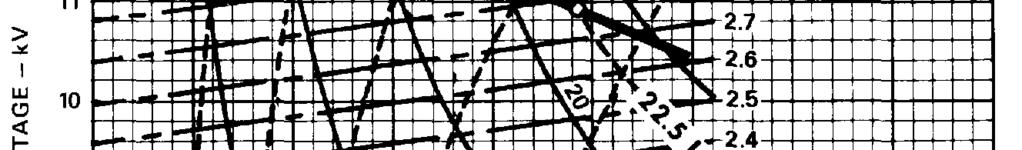
4 Magnetic Field Operation of a BURLE large power magnetron requires a uniform magnetic field coincident with the vertical axis of the tube. High voltage should NEVER be applied to the tube until electromagnet current establishes a stable magnetic field high enough to keep anode current cut-off. Refer to the appropriate tube bulletin for a curve showing the magnetron s cutoff characteristics. For those bulletins with a graph showing typical RF mode characteristics, tube cut-off lies to the right of the threshold. While anode voltage is applied to a large power magnetron, electromagnet current should never fall below the threshold for undercurrent protection to immediately remove anode voltage as protection against this cause of magnetron failure. See Separately Excited Electromagnet -- With a separately excited electromagnet, reasonably good magnetron operating stability is achieved when both anode power supply and electromagnet power supply have about the same line regulation characteristics. In this circumstance, fluctuations in the electromagnet current will be of approximately the right magnitude and in the right direction to compensate for fluctuations in anode voltage. For example, consider a case where initial 8684 magnetron operating conditions are: No-Load Anode Voltage, 13 kv; Full Power Anode Voltage, 11.8 kv; and Electromagnet Current (full power), 3.0 A. Under these conditions, the magnetron operating load line is identified as Load Line A in Figure 1 and RF output at full power is 25 kw. Now, assume that line voltage decreases and, consequently, no-load anode voltage decreases 5% to kv. The new load line resulting from the voltage drop is shown by Load Line B. For an electromagnet power supply with similar line regulating characteristics, electromagnet current will drop 5% to 2.85 A. The new operating point given by the intersection of the short, dashed 2.85 A constant electromagnet curve with Load Line B shows that the RF power output will drop only 2.5 kw to about 22.5 kw. A well-regulated electromagnet power supply would have reduced RF power output to about 16 kw, shown by the intersection of the 3.0 A constant electromagnet current curve and Load Line B. Series Excited Electromagnet -- The sensitivity of RF output to line voltage variations may be further minimized by connecting the electromagnet in series with the magnetron as shown in the 8684 Data Sheet. In this configuration, the magnetron s anode current provides much of the electromagnet excitation, the remaining excitation coming from an auxiliary supply shunted across the electromagnet. It is recommended that the seriesconnected circuit be restricted to applications of not more than 30 kw output because of the tendency of higher-powered, mode when keyed on after a momentary trip-out. The regulating characteristics of the series circuit is illustrated by an example with these initial operating conditions: No-Load Anode Voltage, 13.0 kv; Anode Voltage (full Power), 11.8 kv; Electromagnet Current (full power), 3.0 A; Anode Current, 2.46 A; and Auxiliary Electromagnet Power Supply Current, 0.54 A. The load line for these operating conditions is shown as Load Line A in Figure 2. At the full power operating point, the RF power output is 25 kw. Now, assume the no-load anode voltage drops from 13.0 kv to kv and the active load line shifts to Load Line B as the result of a line voltage drop. The operating point on the new load line can be identified by the intersection of the electromagnet current curve with the new load line. In the series electromagnet circuit, however, the electromagnet current is not constant as before. If we assume that the output of the auxiliary supply is approximately constant at 0.54 A and remembering the electromagnet current is the sum of anode current and auxiliary supply, the electromagnet current curve versus anode current for this example is shown in Figure 2. The intersection of the load line with the electromagnet current curve gives an indicated RF power output of approximately 22.5 kw. Moreover, if the line regulation characteristic of the auxiliary electromagnet power supply approximates that of the high voltage power supply, output of the auxiliary electromagnet supply will drop a little below 0.54 A, thus giving an RF power output between 22.5 and 25 kw. Anode Current Sampling Feedback -- At power levels above 30 kw, where output stability and control is most important, it is recommended that an anode current feedbackcircuit be utilized to control electromagnet current. The circuit should sample anode current, electronically adjusting the electromagnet supply to compensate for variations from the desired anode current. Circuit design can be made as complex as economically justifiable, with adjustable set points, variable up slope and down slope envelopes, proportional control, built-in time delays, and fail-safe provisions. Such a circuit will cut down anode current fluctuations to an irreducible minimum. High Voltage Supply Typically, a full-wave, three-phase power supply is used to provide the magnetron s anode voltage. The allowable ripple and frequency modulation of the output voltage determine the size of the smoothing choke, if any, required in series with the power supply. Design the internal impedance of the supply to limit short circuit current to a maximum of 24 amperes in case of an internal arc-over in the magnetron. Over-current protection should be provided for magnetrons operating up to 30 kw output by using a reliable, high speed, over-current relay in series with the anode to remove voltage from the anode in case of a fault. Adjust the relay for operation as close to maximum plate current as possible without causing unnecessary tripping due to normal transients and line voltage variations. For magnetrons operating above 30 kw useful output, the large amount of energy stored in the power supply filter may require faster protection than that afforded by an over-current relay with a40 to 50 millisecond operating time. Faster protection (5 to 10 microseconds) is achieved by using a high-speed electronic circuitto totally by-pass fault current until mechanical contactors open. Such a circuit may employ a controlled gas tube, such as a thyratron or ignitron, to handle the required energy. -4


5 RF Load When a magnetron is operating into a varying load, changes in frequency, anode current, power output, and filament backheating will all occur. Operation may be highly unstable if the tube is operating in the sink region, Refer to the area of high VSWR between 140 degrees and 160 degrees on the Rieke diagram printed in the tube bulletin of any BURLE magnetron. Although a detailed explanation of the diagram is beyond the scope of this applications note, the user should be aware of these relationships. 2. An oscillating magnetron should be protected from the large amount of power that may be reflected back to the tube from a mis-match of the RF load. A junction circulator, a non-linear ferrite device installed between the wave guide transition and the RF load, passes forward power to the output load essentially unattenuated but deflects reflected power away from the magnetron to a load which absorbs and dissipates the reflected power. Although the magnetrons in many systems operating at 30 kw and less without circulators have demonstrated good life while working into well-matched loads, the absence of a circulator is risky at 30 kw and seriously jeopardizes magnetron life above that level. When a BURLE magnetron is started and operated in the sequence listed in Step by Step Operation, it will always begin oscillating in the sufficient to supply the required anode current. Emission electrons in-step with the magnetron s RF field give up their potential energy to the RF field. Emission electrons out-ofstep with the RF field spiral back and strike the filament with enough energy to cause extra filament heating, called backheating. Abrupt changes in the magnetron s operating conditions, for example: a line voltage jump, a sudden increase in RF load, or a drop in electromagnet current, may cause the tube to to the magnetron than is dropping out of oscillation. Protect the tube against both possibilities. Low filament emission resulting from low filament temperature operation. Low filament temperature causes and corrections include: 1. Insufficient power supplied to the filament. In the oscillating magnetron, filament power is supplied partly by the filament supply. Changes in oscillating conditions change the amount of back-heating. Back-heating changes must be compensated for by adjusting the filament supply setting to maintain the correct hot filament resistance. 2. Reflectivity changes of internal tube parts due to normal tube aging. As the reflectivity of tube parts decreases, filament REFERENCE DATA FOR RADIO ENGINEERS. Fifth ed., Howard W. Sams & Co., Indianapolis, (1968) George B. Collins, editor, McGraw Hill, New York, (1948) MICROWAVE MAGNETRONS, temperature decreases. Adjust for these normal changes by periodically monitoring and adjusting hot filament resistance (see Filament). trons is approximately 1540 MHz. Because tubes and systems are optimized for 915 MHz oscillation, little 1540 MHz energy is are rapid and destructive: 1. Filament temperature increases greatly in a few seconds because of very high back-heating. The overheated filament sags, filament turns sometimes short together electrically, and filament burnout frequently follows. 2. High RF voltagedevelops between the tube s filament terminals and electrical ground, causing equipment component failure, dielectric support breakdown and external arcing. Arcing across the tube s high voltage ceramic insulator is likely to fracture the ceramic. 3. High RF voltage causes internal tube arcing which, in turn, generates gas in the tube due to the energy dissipated. If overload devices operate fast enough to protect the magnetron from total destruction from filament back-heating and external arcing, the gas usually results in additional severe internal arcing and in spurious radiation when the tube is tions: 1. Increased filament resistance shown by lower filament current at constant voltage. 2. Presence of little or no 915 MHz energy. 3. Low efficiency and high anode dissipation. 4. Excessive 1540 MHz radiation from the filament connector area. Withoutthe use of special test equipment, it is frequently difficult mode operation or are the result of internal tube arcs which occasionally occur spontaneously. If excessive anode supply overloading occurs, consult Troubleshooting Hints. relatively stable up to about 1.0 A of anode current. Above this level, anode current becomes unstable and operation is not always predictable. Frequently the tube will arc internally due to the high RF voltages generated. 2. For further information on Rieke diagrams, consult these references: -5-
6 Each BURLE large power magnetron data sheet contains a Figure 3, reproduced from the data sheet for type 8684, illustrates graphically how AJ-2194 electromagnet current and thresholds. Study of Figure 3 shows that avoiding particular combinations of anode voltage and electromagnet current will of electromagnet current is defined as that electromagnet current which allows the magnetron s operating point to intercept tion is a reliable under-current relay in series with the electromagnet that removes anode voltage if the electromagnet current drops close to the critical value for that anode voltage. Assume the following: a transmitter uses a separately-excited electromagnet and a fixed anode voltage supply. The unloaded anode voltage is 14.0 kv and the anode supply s internal impedance is 800 ohms. Anode current of about 2.8 A is needed to obtain 25 kw of useful power output. When anode voltage is on but the tube is biased off, the operating point is between A and B, depending on the electromagnet current. As electromagnet current is reduced, anode current begins to flow at point the electromagnet current is reduced further, the operating point moves down the operating line B C. At C, the anode current required for 25 kw is reached. Now assume that, having oscillated satisfactorily at 25 kw output for a short period, the magnetron drops out of oscillation. The anode current goes to zero, anode voltage rises to the no-load value, and operating This example requires an under-current relay in the electromagnet circuit set to de-energize anode voltage at an electromagnet current very close to 3.0 A. The operating tolerance of the relay is quite narrow for the conditions chosen in the example: if the relay trips much above 3.0 A, the magnetron will not be able to generate 25 kw output power; if the relay operates much below A wider safety margin results from using a power supply with 400 ohms internal impedance. In this case, the no-load anode voltage must be reduced to end up at the same voltage under load. The operating point moves from A to B to C. If the magnetron drops out of oscillation at point C, the operating can be prevented if the electromagnet current stays above 2.75 A. For best protection, set the under current relay just below the value needed to achieve the required power output. Thoroughly test the under-current relay at various settings to assure the relay will always remove anode voltage at the value of electromagnet 2. Always operate with minimum electromagnet current greater anode voltage. Be sure to consider all conceivable operating conditions in selecting an operating range, allowing also for ripple and line regulation. As a further example, consider operating an 8684 at 22.5 kw RF power output with an anode supply having a no-load voltage of 13 kv and internal resistance of 1000 ohms using a separatelyexcited electromagnet. What are the remaining operating parameters, and do the proposed conditions lead to stable operations? Analyze the proposed operating parameters as follows: 1. Draw a 1000-ohm load line on the Typical Performance Characteristics graph at a no-load voltage of 13.0 kv. See Figure Draw an estimated 22.5 kw constant RF power curve through the above load line. 3. Read the operating parameters corresponding to the intersection of the load line and constant RF power curve. From Figure 4, the operating parameters for the example are: Anode Voltage, 10.4 kv; Anode Current, 2.58 A; and Electromagnet Current, 2.63 A. 4. Mark the operating point on the Typical Threshold Characteristics graph corresponding to an anode voltage of 10.4 kv and an electromagnet current of 2.63 A. See Figure Draw an anode no-load voltage line of 13 kv horizontally in mode threshold curve at 6. the operating point in Figure 5. curve, so tube operation will be satisfactory as long as the tube will happen if the tube should drop out of oscillation for reasons already discussed above. In this case, the following sequence of events will occur: 1. The electromagnet current remains constant because the electromagnet is separately excited. 2. Anode current of the 8684 will drop toward zero. 3. Anode voltage of the8684 will rise toward no-load level as the anode power supplycurrent loading drops. On Figure 6, the load line for this series of events follows the constant electrothreshold line at an anode voltage of approximately 12.3 kv. 4. When the anode voltage reaches 12.3 kv, the magnetron will operating level: 1. Select an anode supply with impedance such that no-load anode voltage at the minimum operating electromagnet current. b. will arc almost immediately. -1 mode. During this oscillation, the magnetron filament and anode will overheat, gas will be generated in the tube, and the tube will arc internally. -6-
7 Therefore, the operating conditions proposed in this example are not acceptable for safe magnetron operation. have been avoided-in the example by selecting an anode power supply with lower internal impedance. Using a power supply with an internal resistance of 850 ohms, the operating conditions threshold will not be exceeded at 13.0 kv anode no-load voltage. Hence, the example demonstrates the importance of Step-By-Step Operation Magnetron Installation Unpacking Cut the top seal of the shipping container and open the top cover lids. 2. Remove the four (4) Hardi-Pak spacers on the top corners of the inner shipping container. 3. Cut the top seal of the inner shipping container and open the top cover lids. 4. Remove the manila envelope containing: a. Test Data Sheet b. RF Gasket Installation Instructions. c. Personal Safety Hazard Warning. 5. Remove the rectangular cardboard sleeve, and sit the sleeve on end on a flat work surface. 6. Raise the magnetron package out of the shipping container. Lower the package so that the bottom plywood shipping plate rests flush and securely on the upper end of the cardboard sleeve provided in Step 5. The magnetron will be positioned with the ceramic dome down. 7. Remove the safety wires from each of the four (4) wing nuts. 8. Remove the four (4) wing nuts and washers. 9. Remove the top plywood shipping plate. 10. Open the upper end of the plastic bag encasing the magnetron. Slip the sides of the bag down below the magnetron cooling pipes. Preparation and Installation Assemble the AJ2135 Magnetic Pole Piece to the magnetron. See the section on Magnetron Support Equipment for more details on the AJ2135. Carefully lower the magnetic pole piece over the magnetron s filament terminal while keeping the pole piece slots aligned with the magnetron s coolant tubing. Fasten the AJ2135 Magnetic Pole Piece to the magnetron with six (6) 1/4-28 UNF x 1/2 socket head cap screws. Holding the magnetron-pole piece assembly by the pole piece, lift the assembly clear of the plastic bag. 2. The magnetron was shipped with AJ2138 RF Gasket attached. Check to ensure the gasket is still correctly positioned on the magnetron s RF contact surface. If necessary, reposition the gasket on the magnetron s RF contact surface as shown in RF Gasket Installation Instructions included with the tube. Use the clips provided to hold the gasket in position. Avoid touching the ceramic dome with RF gasket or with bare hands. BURNING, ARCING AND PROBABLE TUBE DAMAGE WILL RESULT IF THE GASKET DOES NOT MAKE GOOD RF CON- NECTION BETWEEN THE MAGNETRON AND THE ELECTRO- MAGNET SEAT AROUND THE ENTIRE CIRCUMFERENCE OF THE GASKET. Lift the magnetron-pole piece assembly by the pole piece for installation in the operating socket. Hold the magnetronpole piece assembly and carefully rotate it to align the assembly with the operating socket. The tube s anode coolant tubing must match the location of the coolant hoses in the magnetron housing and the holes in the pole piece must align with the three studs protruding from the electromagnet. With a last visual check to assure the RF gasket is still in its proper position, carefully insert the magnetron, dome end first, into the electromagnet operating socket. Seat the magnetron squarely in the socket with the three electromagnet studs protruding through the pole piece. Assemble lock washers and nuts on the three studs. If the magnetron is positioned with the ceramic dome UP, push the magnetron upward firmly in the socket with one hand while tightening nuts with the other. Hand tighten the nuts. Check spacing between the pole piece and the magnet at several points. Uniform spacing assures that the tube is seated squarely in the electromagnet. If the spacing between pole piece and electromagnet is not uniform, loosen the three nuts and readjust the magnetron s position until the spacing is uniform. Re-tighten the nuts hand-tight. NOTE: THESE TIGHTENING INSTRUCTIONS APPLY ONLY WHEN LOCK WASHERS ARE USED AS RECOMMENDED. IF LOCK WASHERS ARE NOT USED, THE 2/3 TURN PRESCRIBED WILL BE EXCESSIVE AND WILL BE LIKELY TO CAUSE PERMANENT TUBE DAMAGE. After hand tightening the three nuts and checking to be sure the magnetron is squarely seated, turn the nuts an additional 2/3 turn with a wrench as follows: Turn each nut 60 degrees, or one flat around, in turn. Repeat three more times, completing 2/3 turn (240 degrees or four flats around ). This is equivalent to compressing the gasket by mm ( inch). The torque on each nut will now be newton-meters (20-30 inch-pounds). Filament contact surfaces of the magnetron and the filament connectors must be clean and free from grease and oxide buildup. Position the AJ2136V2 Filament-Cathode Connector squarely against the shoulder of the magnetron terminal. Tighten the connector screw to give a good electrical contact between the connector and the magnetron contact surface. Repeat for the AJ2137V1 Filament Connector. Make cooling connections as follows: a. Connect and clamp air hoses to the AJ2137V1 Filament Connector and to the air inlet on the AJ2192 Waveguide Transition. b. Connect and clamp water hoses to the anode coolant ducts shown in Figure 9. Be sure the direction of water flow is as specified in the tube bulletin for the magnetron type being installed. The spacing between the coolant pipes and all objects at high voltage must be greaterthan 19 mm (3/4 inch).
8 7. Turn on air and water flow for cooling. Adjust flow rates to the values specified in the tube bulletin of the magnetron being installed. Magnetron Operation To minimize the possibility of permanently damaging a magnetron during initial operation, the first-time operator must read and understand the principles of magnetron operation summarized in the section titled Magnetron Operating Considerations. The instructions below assume that the warnings and recommendations under Personnel Safety and Magnetron Protection have been incorporated in the system design. Power On Turn on the filament power in accordance with the recommended procedure for the type of supply being used. Never exceed maximum starting current of 250 A. Set filament voltage and current to the values listed under Test Conditions A on the Test Data sheet of the tube being operated. After filament stabilization of approximately5 minutes, calculate hot filament resistance, dividing filament voltage by filament current. The value calculated should correspond closely with that listed on the tube s Test Data sheet (Figure 10). If the calculated value differs appreciably from the data sheet hot filament resistance, refer to Trouble Shooting Hints below. 2. Set electromagnet current high enough to assure anode current cutoff. Adjust anode voltage to the desired no-load operating level. Reduce electromagnet current smoothly, over several seconds, to increase the magnetron s anode current from cutoff to the desired anode current operating point. Watch metering carefully to be sure that the magne- 5. To restart the magnetron after anode voltage is removed, reset filament current to the starting value and reset electromagnet current to greater than anode current cutoff. Follow the Power On procedure above. Trouble Shooting Hints This short checklist of common problems encountered when using systems with BURLE large power magnetrons assumes the use of magnetron protection circuits as recommended in this Applications Note. The list is not intended as a complete summary of all possible magnetron or system problems. For further assistance with magnetron problems not addressed in this list or the body of this Applications Note, contact Power Tube Applications Engineering, Tube Products Division, BURLE INDUSTRIES, INC., 1000 New Holland Ave., Lancaster, PA , telephone (717) Possible Cause Correction Hot Filament Resistance -- If the measured hot filament resistance differs by more than 2% from the value recorded on the Test Data sheet accompanying the magnetron, correct the cause. High Contact 1. Remove grease and oxide buildup from filament and connector contact surfaces. Resistance 2. Replace AJ2136V2 and AJ2137V1 if worn or distorted. Meter Error 1. Recalibrate meters. 2. Correct line drop due to remote meter location. Low Filament Power 1. Set filament to hot filament resistance specified on Test Data sheet. 2. Increase filament input power in 25 watt steps above Step 1 value to 75 watt max. 3. Reduce filament to Step 1 value and hunt elsewhere. Insufficient filament preheat Increase preheat time at full current Excessive rate of anode current rise Max. increase: 0.5 ampere/second Low filament power 1. Set filament to hot filament resistance specified on Test Data sheet. 2. Increase filament input power in 25 watt steps above Step 1 value to 75 watt max. 3. Reduce filament to Step 1 value and hunt else-where. Short Magnetron Life due to Filament Burn-Out Excessive filament temperature during operating life RF Arcing to Anode Coolant Duct Close Spacing Reduce filament input on future tubes to compensate for back-heating (control hot filament resistance). Reflected power from 1. Add circulator and dummy load. mis-matched load 2. Correct circulator malfunction. 3. Match load mm (3/4 inch) minimum spacing from high voltage surfaces to anode ducts.
9 Waveguide Transition Tuner Setting Originally, AJ2192 Waveguide Transitions were built with an adjustable tuner. In current AJ2192s, the tuner has been replaced with a fixed stub. The adjustable tuner was pre-set in the factory and needs no further adjustment. The lock nut on the tuner must be kept tight at all times to prevent overheating. If the tuner should inadvertently be turned, reset it to mm (1.290 in.) from the end of the tuner to the end of the flange. See Figure 11. Magnetron Support Equipment For safe and satisfactory operation of BURLE large power magnetrons, BURLE INDUSTRIES, INC. recommends use of the following parts and assemblies: BURLE Type Number Description AJ2135 AJ2136V2 AJ2137V1 AJ2138 AJ2192 AJ2194 Magnetic Pole Piece Filament-Cathode Connector Filament Connector RF Gasket Waveguide Transition Electromagnet One unit of each of the recommended parts and assemblies is required for the proper operation of a BURLE magnetron. All items except the RF gasket may be used in the subsequent installation of replacement tubes. Do NOT reuse RF gaskets. Keep several RF gaskets on hand for possible use in reinstalling tubes. The use and precautions related to the parts and assemblies described in this section are discussed under Magnetron Installation. Operating Socket The AJ2192 Waveguide Transition and the AJ2194 Electromagnet are shipped in separate cartons for maximum protection against shipping damage. The components, when assembled as described below, form a complete operating socket for BURLE large power magnetrons. Magnetic Pole Piece The AJ2135 Magnetic Pole Piece holds the magnetron in its correct position within the electromagnet and shapes the magnetic field for proper focusing of the magnetron s electron beam. Filament-Cathode Connector The AJ2136V2 Filament-Cathode Connector makes electrical contact to the filament-cathode terminal of the magnetron. It features a molded attenuator which suppresses spurious radiation from the high voltage insulator area of the magnetron. Typical spurious radiation attenuation is 12 db: typical AC or DC current is 115 amperes. Filament Connector The AJ2137V1 Filament Connector makes electrical contact to the filament terminal of the magnetron. It contains a duct to permit forced air cooling of the filament terminal, the filament insulator, and the filament-cathode connector. Typical AC or DC current is 115 amperes. RF Gasket The AJ2138 RF Gasket is a mesh-type gasket to produce an RF connection between the magnetron and the waveguide transition. Operating Socket Assembly Instructions The Waveguide Transition and Electromagnet are shipped separately to prevent damage to the waveguide transition. Accessories necessary to complete the assembly of the waveguide transition and electromagnet are enclosed in two packets and shipped inside the corrugated box with the waveguide transition. -9- Waveguide Transition The AJ2192 Waveguide Transition couples the RF energy from the magnetron to a standard WR975 Waveguide. Its flange mates with a standard EIA Waveguide Flange CPR975F. Electromagnet The AJ2194 Electromagnet is liquid-cooled and will control the anode current for all specified values of anode-cathode voltage. It focuses the magnetron s electron beam as required for efficient performance. Maximum Ratings, Absolute Maximum Values DC Electromagnet Voltage.,.,,,,...,.,...,,,,,,,.., v Peak Voltage (Transient) I v DC Electromagnet Power watts General Data Electrical: Coil Current at 39 volts,,,...,,,,,,..,., A Mechanical: Overall Height, Max mm (6.25 in.) Greatest Diameter, Max mm (12.80 in.) Weight, Uncrated kg (128 lb.) Weight, Crated 83.0 kg (83 lb.) Thermal: Liquid cooling of the electromagnet coil is essential. See Cooling section for further discussion. Metal Surface Temperature Flush all coolant from coolant courses for shipping or storage at temperatures below freezing. Typical Water Flow for Coil.95 I/min (0.25 gpm) Maximum Pressure Drop at.95 I/min (0.25 gpm) bar (10 psi) Maximum Outlet Water Temperature Maximum Inlet Water Pressure, Gauge bars (100 psi) Theelectromagnet is secured to a wooden skid by a metal band. It is enclosed with a wooden cover secured to the skid by two metal bands. While severing the metal bands during the uncrating operation, use care to prevent personal injury from the whipping ends of the bands when the bands are cut. Item Description Quantity 1 Electromagnet 1 2 Waveguide Transition 1 3 Pole Piece NC x l/2 Flat Head Screws 6 5 l/4-20 NC x 3/4 Socket Head Screws 6 6 3/l 6 Hex Key 1 7 l/4 Flat Washers 8 8 l/4-20 NC x 6 3/4 Hex Head Bolts 4 9 l/4 Lo&washers /a -16 Hex Nuts /8 Lockwashers 3 12 Polyethylene Air Sleeve 1

 to it using the six 8-32 NC x 1/2 Flat Head Screws (4) as shown in")
 on supports")
 is in position as shown in")

 are aligned with the")

 and, Step 5: using the 3/16 Hex")
 as shown in Detail B of Figure 17. Do NOT tighten screws.")
 at each of the four 1/4-20 NC x 6 3/4 Hex Head")
 beneath the head of the four 1/ 4-20")
 and Washer pairs (7) into the mounting brackets. Do NOT tighten.")
 and the welded flange of the")

 and Lockwashers (11), round")

10 Items 1 and 2 must be ordered separately. Items 3-12 are supplied with Item 2. Step 1: Lay the elctromagnet (1) on its side and attach the Pole Piece (3) to it using the six 8-32 NC x 1/2 Flat Head Screws (4) as shown in Figure 15 and Detail A of Figure 17. Step 2: Step 3: Step 4: - Place the Waveguide Transition (2) on supports with the air inlet down as shown in Figure 16. Be sure the Polyethylene Air Sleeve (12) is in position as shown in Details A and B of Figure 17. Position the Electromagnet and Pole Piece assembly from Step 1 on the Waveguide Transition (2) in accordance with Figure 17, assuring that the counterbored 1/4 inch holes of the Pole Piece (3) are aligned with the 1/4-20 tapped holes in the Waveguide Transition (2). Check for the correct orientation of the electromagnet coolant ducts. Insert the six l/4-20 NC x 3/4 Socket Head Screws (5) in the counterbored 1/4 clearance holes in the Pole Piece (3) and, Step 5: using the 3/16 Hex Key (6), start the screws into the threaded holes in the Waveguide Transition (2) as shown in Detail B of Figure 17. Do NOT tighten screws. Position two 1/4 Flat Washers (7) between the Waveguide Transition (2) and the Electromagnet (1) at each of the four 1/4-20 NC x 6 3/4 Hex Head Bolt (8) positions. Refer to Figure 17. Step 6: Place a 1/4 Lockwasher (9) beneath the head of the four 1/ 4-20 NC x 6 3/4 Hex Head Bolts, threading the bolts through the Electromagnet (1) and Washer pairs (7) into the mounting brackets. Do NOT tighten. Step 7: Tighten the six 1/4-20 NC x 3/4 Socket Head Bolts (5). Note: The contact between the Pole Piece (3) and the welded flange of the waveguide Transition (2) must be a good RF seal to prevent burning and RF leakage. Step 8: Tighten the four (4) 1/4-20 NC x 6 3/4 Hex Head Bolts (8). Step 9: Install the three 3/8 Hex Nuts (10) and Lockwashers (11), round side down, on the three threaded rods of the Electromagnet (1). Step 10: Mount the completed operating socket with the axis of the Electromagnet vertical. Support the assembly by the mounting brackets shown in Figure ANODE CURRENT - AMPERES 92LS-5145 Figure 1 - Performance Characteristics with Separately- Excited Electromagnet Figure 3 - RF Mode Characteristics ANODE CURRENT - AMPERES Figure 2- Performance Characteristics with Series- Excited Electromagnet -10-


11 92LS ANODE CURRENT - AMPERES 1000-ohm Load Line Figure 7 - Performance Characteristics, 850-ohm Load Line - 0 Load Line ELECTROMAGNET CURRENT -AMPERES Figure 8 - Load Line 92LS-5140 ANODE COOLANT ANODE COOLANT 92LM-1934R1 Figure 9 - Filament End of Magnetron -11-
12 LARGE POWER MAGNETRON TEST DATA TUBE TYPE NUMBER: SERIAL NUMBER: TESTED BY: DATE: QUALITY ASSURANCE: DATE: PARAMETERS NOTE UNITS TEST CONDITIONS 5 FILAMENT VOLTAGE V FILAMENT CURRENT A HOT FILAMENT RESISTANCE 1. ohms. EFFECTIVE FILAMENT POWER W FILAMENT SUPPLY POWER 2 w ELECTROMAGNET CURRENT A ANODE VOLTAGE kv ANODE CURRENT A LOAD VSWR R.F. POWER OUTPUT kw TUBE EFFICIENCY % FREQUENCY MHz NO-LOAD FlLAMENT VOLTAGE 4. v TEST CONDITIONS A B C NOTES: PUSHING FACTOR MHz/A PULLING FACTOR MHz COOLANT PRESSURE DROP AT psi. 1. THE ABSOLUTE MAXIMUM HOT FllAMENT RESISTANCE AT WHICH MIS TUBE MAY BE OPERATED IS ThE VALUE SPECIFIED PLUS ohms. 2 FllAMENT SUPPLY POWER = (FlLAMENT VOLTAGE) X (FILAMENT CURRENT) 3. EFFECTIVE BACK-HEATING POWER = (EFFECTIVE FILAMENT POWER) - (FlLAMENT SUPPLY POWER) 4. CUT Off ANODE CURRENT BY INCREASING ELECTROMAGNET CURRENT WHILE THE TUBE IS OPERATING AT RF. POWER OUTPUT LISTED. READ NO-LOAD FILAMENT VOLTAGE AND CURRENT WITHOUT ADJUSTING FILAMENT POWER SUPPLY 5. TEST CONDITIONS A IS WITH P out=0; TEST CONDITION B IS AT APPROXIMATELY 80% RATED POWER TEST CONDITION C IS AT APPROXIMATELY 100% RATED POWER OBSERVE AIR AND LIQUID COOLING REQUIREMENTS AND AU PRECAUTIONS AS DESCRIBED IN OPERATION AND USE OF BURLE INDUSTRIES, INC. LARGE POWER MAGNETRONS AN-4985 AND IN INDIVIDUAL TUBE TYPE BULLETIN MAGADATA Figure
13 Figure 11 - AJ2192 Waveguide Transition 92LS-5131 Figure 13 - AJ2192 Flange to Mate CPR975F (225.6) II 92LS-5130 Figure 12 - AJ2192 Dimensional Outline Figure 14 - AJ2194 Dimensional Outline -13-


14 Figure 15 - Assembly of Electromagnet and Pole Piece Figure 17 - Assembly of Electromagnet and Waveguide Transition LS-5148 Figure 16 - Waveguide Transition Positioned on Supports -14-
4648, 4648V1 Power Tube
 4648, 4648V1 Power Tube RF Power Amplifier Tetrode CW Output Up To 350 kw Pulsed Output Up To 1000 kw Peak Operation To 45 MHz PowerGainUpTo28dB The BURLE 4648 is designed to operate in a wide variety
S93419E Power Tetrode
 S93419E Power Tetrode VHF Linear Beam Power Tetrode Full Input to 300 MHz Liquid Cooled Anode 125 kw CW Power Output 16dB Gain 75% Efficiency The BURLE S93419E is designed specifically for use in high-gain,
Maximum output power with circulator Wo 6 kw. Maximum output power without circulator Wo 5 kw
 Packaged, metal-ceramic, water cooled continuouswave magnetron with integral RF cathode filter intended for use in industrial microwave heating applications. The tube features a quick- heating cathode,
4616 Power Tube. Super-Power Beam Power Tube. -Pulse Length to 2500 Microseconds. -2 Megawatts Short-Pulse Power Kilowatts Long-Pulse Power
 4616 Power Tube Super-Power Beam Power Tube -Pulse Length to 2500 Microseconds -2 Megawatts Short-Pulse Power -275 Kilowatts Long-Pulse Power -Low Filament Power for Airborne Use BURLE-4616 is a water-cooled
TESCO THE EASTERN SPECIALTY COMPANY Date: 05/04/15 Canal Street and Jefferson Avenue Bristol, PA 19007
 Table of Contents DESCRIPTION PAGE 1.1 Cat. 1044A (What it is)... 2 1.2 Selector Switches... 2 1.3 Leads... 2 CURRENT TRANSFORMERS 2.1 Tests... 2 2.2 Function of Catalog 1044A... 3 2.3 Internal C.T. Defects...
A - Add New Information C - Change Existing Information D - Delete Information. Page 7. Delete the fourth paragraph beginning CAUTION
 ABB Effective: November 1990 This Addendum Supersedes all Previous Addenda Addendum to Instruction Leaflet 41-137.3H Type KRD-4 Directional Overcurrent Ground Relay A - Add New Information C - Change Existing
PROCESS ELECTRONICS CORPORATION
 MINIVERTER MANUAL PROCESS ELECTRONICS CORPORATION 100 BRICKYARD ROAD MOUNT HOLLY, NORTH CAROLINA 28120 TELEPHONE (800) 421-9107 FAX (704) 827-9595 SALES@PECRECTIFIER.COM WWW.PECRECTIFIER.COM SOLID STATE
CR193 Vacuum Limitamp* Contactors
 GE Electrical Distribution GEH-5306C Maintenance Instructions CR193 Vacuum Limitamp* Contactors Contents Section 1 Introduction... 3 General... 3 Section 2 Description... 4 Principle of Operation... 4
3. OPERATION 2.1. RESTRAINT CIRCUIT 2.6. INDICATING CIRCUIT 2.2. OPERATING CIRCUIT 2.7. SURGE PROTECTION CIRCUIT 2.3.
 41-348.1H Type SA-1 2.1. RESTRAINT CIRCUIT The restraint circuit of each phase consists of a center-tapped transformer, a resistor, and a full wave rectifier bridge. The outputs of all the rectifiers are
2.0 CONSTRUCTION 3.0 OPERATION. SA-1 Generator Differential Relay - Class 1E 2.5 TRIP CIRCUIT
 41-348.11C SA-1 Generator Differential Relay - Class 1E 2.0 CONSTRUCTION The type SA-1 relay consists of: Restraint Circuit Sensing Circuit Trip Circuit Surge Protection Circuit Operating Circuit Amplifier
Figure 1. Type CWP-1 Ground Relay (Front View) Figure 2. Type CWP-1 Ground Relay (Rear View) E
 Figure 2. Type CWP-1 Ground Relay (Rear View) E") Figure 1. Type CWP-1 Ground Relay (Front View) Figure 2. Type CWP-1 Ground Relay (Rear View) 41-242.5E 2 Typical 60 Hertz time product curves for the type CWP-1 relay are shown in Figure 4 with 100 volts
Figure 1. Type CWP-1 Ground Relay (Front View) Figure 2. Type CWP-1 Ground Relay (Rear View) 41-242.5E 2 Typical 60 Hertz time product curves for the type CWP-1 relay are shown in Figure 4 with 100 volts
INSTRUCTION MANUAL ACTUATOR CLASSE I TYPE MA, MB
 ACTUATOR CLASSE I TYPE MA, MB CONTENTS Page : 2/13 PRODUCT DESCRIPTION General description 3 Product specification 5 INSTALLATION Storage 6 Unpacking 7 Handling 7 Installation : Mechanical 7 Installation
3.2. Current Limiting Fuses. Contents
 .2 Contents Description Current Limiting Applications................. Voltage Rating.......................... Interrupting Rating....................... Continuous Current Rating................ Fuse
3.0 CHARACTERISTICS E Type CO-4 Step-Time Overcurrent Relay
 41-106E Type CO-4 Step-Time Overcurrent Relay A core screw accessible from the top of the switch provides the adjustable pickup range. The IIT contacts are connected in the trip circuit to trip instantaneously.
B CW POWER RELAY
 41-241.31B CW POWER RELAY nected in such a way that current, (I A ), leads voltage, (V BA ), by 150 degrees when the motor is operating at unity power factor. Loss of excitation to the motor causes a large
SHORT-STOP. Electronic Motor Brake Type G. Instructions and Setup Manual
 Electronic Motor Brake Type G Instructions and Setup Manual Table of Contents Table of Contents Electronic Motor Brake Type G... 1 1. INTRODUCTION... 2 2. DESCRIPTION AND APPLICATIONS... 2 3. SAFETY NOTES...
COM Overcurrent Relay
 41-102.1B COM Overcurrent Relay Figure 1: COM-5 Class 1E Relay (Front View) 9664A28 Photo Figure 2: COM-5 Class 1E Relay (Rear View) 9664A29 Photo Photo needed here 2 COM Overcurrent Relay 41-102.1B 3
2.0 CONSTRUCTION AND OPERATION 3.0 CHARACTERISTICS K. CO (HI-LO) Overcurrent Relay
 Overcurrent Relay") 41-100K 2.0 CONSTRUCTION AND OPERATION The type CO relays consist of an overcurrent unit (CO), either an Indicating Switch (ICS) or an ac Auxiliary Switch (ACS) and an Indicating Instantaneous Trip unit
41-100K 2.0 CONSTRUCTION AND OPERATION The type CO relays consist of an overcurrent unit (CO), either an Indicating Switch (ICS) or an ac Auxiliary Switch (ACS) and an Indicating Instantaneous Trip unit
OPERATING AND MAINTENANCE MANUAL. Primary Current Injection Test Set. 750ADM-H mk2
 OPERATING AND MAINTENANCE MANUAL Product: Type: Primary Current Injection Test Set 750ADM mk2 750ADM-H mk2 DESIGNED AND MANUFACTURED BY: T & R Test Equipment Limited 15-16 Woodbridge Meadows, Guildford,
Presented to the IAPMO Standards Review Committee on December 9, 2013
 Summary of Substantive Changes between the 2010 edition including Updates No. 1 and No. 2 dated September 2010 and August 2011 and the 2013 edition of CSA C22.2 No. 14 Industrial control equipment Presented
ABB ! CAUTION. Type KRV Directional Overcurrent Relay E 1.0 APPLICATION 2.0 CONSTRUCTION AND OPERATION. Instruction Leaflet
 ABB Instruction Leaflet 41-137.2E Effective: February 1994 Supersedes I.L. 41-137.2D, Dated February 1973 ( )Denotes Change Since Previous Issue. Type KRV Directional Before putting relays into service,
Technical Explanation for Inverters
 CSM_Inverter_TG_E_1_2 Introduction What Is an Inverter? An inverter controls the frequency of power supplied to an AC motor to control the rotation speed of the motor. Without an inverter, the AC motor
Service Guide for XUGUANG Electron Tubes
 Service Guide for XUGUANG Electron Tubes 1 Usage and Maintenance 1.1 The electron tubes should be vertically placed and transported in original packages. Meanwhile, these packages should be carefully handled
Matrix AP 400V 690V INSTALLATION GUIDE. Quick Reference. ❶ How to Install Pages 6 20 ❷ Startup/Troubleshooting Pages WARNING
 Matrix AP 400V 690V INSTALLATION GUIDE FORM: MAP-IG-E REL. May 2017 REV. 002 2017 MTE Corporation WARNING High Voltage! Only a qualified electrician can carry out the electrical installation of this filter.
Matrix APAX. 380V-415V 50Hz TECHNICAL REFERENCE MANUAL
 Matrix APAX 380V-415V 50Hz TECHNICAL REFERENCE MANUAL WARNING High Voltage! Only a qualified electrician can carry out the electrical installation of this filter. Quick Reference ❶ Performance Data Pages
Svetlana 3CX15,000H3 Medium-Mu Industrial Power Triode
 Medium-Mu Industrial Power Triode T he Svetlana 3CX15,H3 is a highperformance ceramic/metal power triode designed for use in oscillator, amplifier, or modulator service. The ceramic is glazed to facilitate
Types of Motor Starters There are several types of motor starters. However, the two most basic types of these electrical devices are:
 Introduction Motor starters are one of the major inventions for motor control applications. As the name suggests, a starter is an electrical device which controls the electrical power for starting a motor.
Cat. No. I526-E1-1 USER S MANUAL 3G3IV-PLKEB2 /4. Braking Resistor Units 3G3IV-PCDBR2 B/4 B. Braking Units
 Cat. No. I526-E1-1 USER S MANUAL 3G3IV-PLKEB2 /4 Braking Resistor Units 3G3IV-PCDBR2 B/4 B Braking Units Thank you for choosing an OMRON Braking Resistor Unit and Braking Unit. Proper use and handling
Variable Frequency Drive Basics
 Variable Frequency Drive Basics Contact us Today for a FREE quotation to deliver this course at your company?s location. https://www.electricityforum.com/onsite-training-rfq Variable Frequency Drives are
320 to 327 M Series Low and Medium Voltage Motor Protection Relays
 1. Protection Features 320 to 327 M Series Low and Medium Voltage Motor Protection Relays INSTALLATION AND SETTING UP PROCEDURE Overloading (for both cyclic and sustained overload conditions) Start stall
MAHALAKSHMI ENGINEERING COLLEGE TIRUCHIRAPALLI
 MAHALAKSHMI ENGINEERING COLLEGE TIRUCHIRAPALLI 621213 QUESTION BANK --------------------------------------------------------------------------------------------------------------- Sub. Code : EE2402 Semester
SERVICE AND REPAIR PARTS NEMA SIZE 3, SINGLE POLE, NORMALLY OPEN, P/N SERIES NEMA SIZE 4, SINGLE POLE, NORMALLY OPEN, P/N SERIES
 Hubbell Industrial Controls, Inc. Instructions 5210 SERVICE AND REPAIR PARTS NEMA SIZE 3, SINGLE POLE, NORMALLY OPEN, P/N 59364 SERIES NEMA SIZE 4, SINGLE POLE, NORMALLY OPEN, P/N 59345 SERIES Publication
Svetlana 3CX6000A7 / YU148 High-Mu Power Triode
 High-Mu Power Triode T he Svetlana 3CX6000A7 / YU148 is a high-performance ceramic/ metal power triode designed for use in zero-bias, RF amplifier service, and modulator service. A modern mesh filament
REFERENCE MANUAL FORM: MX-TRM-E REL REV MTE
 Matrix APAX 380V-415V 50Hz TECHNICAL REFERENCE MANUAL FORM: MX-TRM-E REL. September 2014 REV. 002 2014 MTE Corporation WARNING High Voltage! Only a qualified electrician can carry out the electrical installation
SINGLE DUCT TERMINAL UNITS
 www.igcaire.com SINGLE DUCT TERMINAL UNITS Direct Digital Control, Pressure Independent FEATURES 22 Gauge Galvanized Steel Casing Construction with a 20 Gauge Casing Option that Provides Strength and Product
ProTrip Conversion Kits. For GE Types AK-15, AK-25, and AKU- 25 Low-Voltage Power Circuit Breakers INTRODUCTION. DEH Installation Instructions
 DEH 40026 Installation Instructions g ProTrip Conversion Kits For GE Types AK-15, AK-25, and AKU- 25 Low-Voltage Power Circuit Breakers INTRODUCTION GE Conversion Kits are designed for upgrading existing
Ledex Drive Electronics and Coil Suppressors
 Ledex and Coil Suppressors Ledex Coil Suppressors A voltage is generated by a changing magnetic field in proximity to a currentcarrying member. The equation E = N dø /dt, describes this by saying that
Standby Power Systems
 Source: Power Quality in Electrical Systems Chapter 13 Standby Power Systems The term standby power systems describes the equipment interposed between the utility power source and the electrical load to
Direct On Line (DOL) Motor Starter. Direct Online Motor Starter
 Motor Starter. Direct Online Motor Starter") Direct On Line (DOL) Motor Starter Direct Online Motor Starter Different starting methods are employed for starting induction motors because Induction Motor draws more starting current during starting.
Direct On Line (DOL) Motor Starter Direct Online Motor Starter Different starting methods are employed for starting induction motors because Induction Motor draws more starting current during starting.
Instruction Manual for BC-20 Battery Charger and LB-20 Line Booster
 Instruction Manual for BC-20 Battery Charger and LB-20 Line Booster K&W Engineering, Inc. Marion, Iowa Revision 3 30 November 1994 Instruction Manual for BC-20 Instruction Manual and LB-20 Line Booster
SECTION DC POWER SUPPLY/BATTERY CHARGER
 SECTION 26 33 05 PART 1 - GENERAL 1.1 THE REQUIREMENT A. The CONTRACTOR shall provide the single-phase heavy-duty industrial battery charger and all accessories required, complete and operable, in accordance
Compact Proportional Solenoid Valve
 Compact Proportional Solenoid Valve Series Repeatability: % or less Hysteresis:1% or less Fluid Flow rate control range Note) Series Air, Inert gas to L/min to L/min Note) Varies depending on the model.
INSTALLATION INSTRUCTIONS
 Page 1 of 2 Ref: IW012346 Rev 4 July 03 Indicators Saxon & Fiesta Series Products Covered 012-**, 013-**, 014-** & 016-** Installation The product should be panel mounted using the mounting kit provided.
Dual Power. Protection. Protection
 54 Fault Clearing Systems by Damien Tholomier., AREVA T&D Automation, Canada Dual Power Single Battery What if it? Short circuits and other abnormal power system conditions are very rear, but may result
Troubleshooting & Maintenance for Linear Fluorescent Lighting
 Troubleshooting & Maintenance for Linear Fluorescent Lighting Suggestions for Fluorescent Fixture Maintenance Preventing a problem from occurring is always more desirable and economical than fixing it
SOLAR LIGHTING CONTROLLER SUNLIGHT MODELS INCLUDED IN THIS MANUAL SL-10 SL-10-24V SL-20 SL-20-24V
 SOLAR LIGHTING CONTROLLER OPERATOR S MANUAL SUNLIGHT MODELS INCLUDED IN THIS MANUAL SL-10 SL-10-24V SL-20 SL-20-24V 10A / 12V 10A / 24V 20A / 12V 20A / 24V 1098 Washington Crossing Road Washington Crossing,
AIR COOLED RECTIFIER SPECIFICATION S-50-A
 SPECIFICATIONS AIR COOLED RECTIFIER Spec50a1 5JAN1999 SPECIFICATION S-50-A HIGH VOLTAGE SINGLE TRANSFORMER AIR COOLED RECTIFIER Standard output power range: 250 to 600 volts at 100 to 1,200 amperes TECHNICAL
CONTROL FEATURES AVAILABLE OPTIONS
 Vari Speed A2000 TABLE OF CONTENTS Control Features Options Application Data Operating Condition s Control Ratings Chart Mounting Dimensions Installation and Wiring Typical Wiring Diagram Schematic (Block
UNIT VIBRATOR MODELS 60U AND 70U
 VM-3560B Installation, Operation and Maintenance Instructions UNIT VIBRATOR MODELS 60U AND 70U ERIEZ MAGNETICS HEADQUARTERS: 2200 ASBURY ROAD, ERIE, PA 16506 1440 U.S.A. WORLD AUTHORITY IN ADVANCED TECHNOLOGY
MICRO WELD MODEL DP1 & DP2 HEAVY DUTY NON-FERROUS BUTT WELDERS MICRO PRODUCTS COMPANY SERVICE MANUAL
 MICRO WELD MODEL DP1 & DP2 HEAVY DUTY NON-FERROUS BUTT WELDERS MICRO PRODUCTS COMPANY SERVICE MANUAL 1 TABLE OF CONTENTS 1.0 SPECIFICATIONS 2.0 GENERAL OPERATING INSTRUCTIONS 3.0 BASIC OPERATING PARTS
Control Relays Overview
 Control Relays Overview DESIGN FEATURES Among the advances Agastat Control Relays offer over existing designs is a unique contact operating mechanism. An articulated arm assembly amplifies the movement
TS-E TURBO STEAM ELECTRIC COUNTERTOP CONVECTION STEAMER PARTS AND SERVICE MANUAL
 TS-E TURBO STEAM ELECTRIC COUNTERTOP CONVECTION STEAMER PARTS AND SERVICE MANUAL EFFECTIVE JUNE 12, 2017 Superseding All Previous Parts Lists. The Company reserves the right to make substitution in the
Abbeon Cal, Inc. Model BD-50E HIGH FREQUENCY GENERATOR OPERATING MANUAL
 Abbeon Cal, Inc. Model BD-50E HIGH FREQUENCY GENERATOR OPERATING MANUAL DESCRIPTION. The Model BD-50E is a rugged tester designed for testing tank lining and other applications where extended use is necessary.
XLM 62V Energy Storage Module
 Technical Note 10406 XLM Energy Storage Module XLM 62V Energy Storage Module Introduction The XLM energy storage modules are self-contained energy storage devices comprised of twenty-three individual supercapacitor
Load Cell Troubleshooting
 VPG TRANSDUCERS Load Cells Application Note VPG-08 Scope Load cells are designed to sense force or weight under a wide range of adverse conditions; they are not only the most essential part of an electronic
INSTALLATION & MAINTENANCE MANUAL
 A Subsidiary of Dynamic Instruments INSTALLATION & MAINTENANCE MANUAL A Subsidiary of Dynamic Instruments 3860 Calle Fortunada San Diego, CA 92123-1825 Phone: 1-(800) 821-5831 Web Site: hardyinst.com (858)
TIME OF FLIGHT Components from:
 TIME OF FLIGHT Components from: JORDAN TOF PRODUCTS, INC. 990 Golden Gate Terrace Grass Valley, CA 95945 Phone: (530) 272-4580 Fax: (530) 272-2955 Web: www.rmjordan.com Email: info@rmjordan.com INSTRUCTION
Horizontal Circuit Switchers
 > Transformer Protection > CIRCUIT SWITCHERS C A T A L O G B U L L E T I N General Application Southern States Types CSH and CSH-B Horizontal Circuit Switchers provide an economical, versatile, space saving
The Rotating Anode X-Ray Tube
 The Rotating Anode X-Ray Tube The rotating Anode tube assemble is a complex piece of electro-mechanical engineering comprising of around 350 parts taking 150 assembly operations and can cost as much as
Single Pole Circuit Protectors 55. Multi-Pole Circuit Protectors 56. Configurations 58. Operating Characteristics 59.
 Single Pole Circuit Protectors 55 Multi-Pole Circuit Protectors 56 Configurations 58 Operating Characteristics 59 Delay Curves 60 Specifications 61 Decision Tables 62 SINGLE POLE CIRCUIT PROTECTORS The
MICRO WELD MODEL AUF-8 HEAVY DUTY FERROUS BUTT WELDERS MICRO PRODUCTS COMPANY SERVICE MANUAL
 MICRO WELD MODEL AUF-8 HEAVY DUTY FERROUS BUTT WELDERS MICRO PRODUCTS COMPANY SERVICE MANUAL 1 TABLE OF CONTENTS 1.0 SPECIFICATIONS 2.0 GENERAL OPERATING INSTRUCTIONS 3.0 BASIC OPERATING PARTS 4.0 BASIC
Horizontal Circuit Switchers
 > Transformer Protection > CIRCUIT SWITCHERS C A T A L O G B U L L E T I N General Application Southern States Types CSH and CSH-B Horizontal Circuit Switchers provide an economical, versatile, space saving
Components of Hydronic Systems
 Valve and Actuator Manual 977 Hydronic System Basics Section Engineering Bulletin H111 Issue Date 0789 Components of Hydronic Systems The performance of a hydronic system depends upon many factors. Because
1 THE WOLVERTON SYSTEM OF TRAIN LIGHTING.
 1 THE WOLVERTON SYSTEM OF TRAIN LIGHTING. The Wolverton equipment is a single battery system utilising a plain shunt wound dynamo. The dynamo is controlled by an automatic field regulator which senses
ALTERNATOR DE-EXCITATION WITH K1 AND K2 ON ANALOGUE
 Application Guidance Notes: Technical Information from Cummins Generator Technologies AGN 023 AVR Features ALTERNATOR DE-EXCITATION WITH K1 AND K2 ON ANALOGUE AVRs On STAMFORD alternators, analogue AVR
Svetlana 3CX2500H3 Medium-Mu Power Triode
 Svetlana 3CX25H3 Medium-Mu Power Triode T he Svetlana 3CX25H3 is a highperformance ceramic/metal power triode designed for use in amplifier, oscillator, or modulator service. The ceramic is glazed to facilitate
Brushed. Brushed. Brushed Motor
 Kelly Kelly Kelly Kelly KD KD KD KD Series Series Series Series DC DC DC DC Motor Motor Motor Motor Controller Controller Controller Controller User User User User s Manual Manual Manual Manual V 2.5 2.5
AF series contactors (9 2650)
") R E32527 R E39322 contactors General purpose and motor applications AF series contactors (9 2650) 3- & 4-pole contactors General purpose up to 2700 A Motor applications up to 50 hp, 900 kw NEMA Sizes 00
R E32527 R E39322 contactors General purpose and motor applications AF series contactors (9 2650) 3- & 4-pole contactors General purpose up to 2700 A Motor applications up to 50 hp, 900 kw NEMA Sizes 00
Data Bulletin. Ground-Censor Ground-Fault Protection System Type GC Class 931
 Data Bulletin 0931DB0101 July 2001 Cedar Rapids, IA, USA Ground-Censor Ground-Fault Protection System Type GC Class 931 09313063 GT Sensor Shunt Trip of Circuit Interrupter Window Area for Conductors GC
INTRODUCTION Principle
 DC Generators INTRODUCTION A generator is a machine that converts mechanical energy into electrical energy by using the principle of magnetic induction. Principle Whenever a conductor is moved within a
Ensuring the Safety Of Medical Electronics
 Chroma Systems Solutions, Inc. Ensuring the Safety Of Medical Electronics James Richards, Marketing Engineer Keywords: 19032 Safety Analyzer, Medical Products, Ground Bond/Continuity Testing, Hipot Testing,
BASIC TROUBLESHOOTING START / STOP PUSHBUTTONS, PILOT LIGHTS, RELAYS, TIMER LIMIT SWITCHES, FLOW SWITCHES, THERMAL SWITCHES, AND OVERLOAD RELAYS.
 BASIC TROUBLESHOOTING FOUR BASIC BUILDING BLOCKS OF A PLATING RECTIFIER: 1. ELECTRICAL CONTROLS 2. AC POWER CIRCUITS 3. DC POWER CIRCUITS 4. ELECTRONIC CONTROL 1. ELECTRICAL CONTROLS START / STOP PUSHBUTTONS,
10000AR X2 INSTALLATION MANUAL
 10000AR X2 INSTALLATION MANUAL REV 2.0b COPYRIGHT 1997 Xenotech, Inc. PAGE 1 BRITELIGHT 10000AR SPECIFICATIONS POWER SUPPLY MAIN POWER INPUT INPUT VOLTAGE: INPUT CURRENT: PHASE: FREQUENCY: 380 VAC. 20
Contacts The moveable contact, which is the one affected by the armature is sometimes referred to as the hinge contact.
 Relays & Wiring 101 Basically, a relay is an electrically operated, remotely controlled switch. A simple electromagnetic relay is an adaptation of an electromagnet. It consists of a coil of wire surrounding
Power & High Voltage Joslyn Hi-Voltage Overhead Reclosers & Switches H-220. Series HVI Hi-Velocity Interrupter Attachment
 Use load interrupter attachments to enable loop sectionalizing, line dropping, load breaking and transformer-magnetizing current interruption. Increase the capability of your disconnect switches by adding
LACT MEASUREMENT. Total Head = Or PSI = S.G. 2.31
 LACT MEASUREMENT Prepared By: Ken A. Steward. P.E. Linco-Electromatic, Inc. 4580 West Wall Street Midland, Texas 79703 The Operation of L.A.C.T. Units The simplest approach to the understanding of the
ATP-2040 Electric Damper Actuator/Transmitter
 ATP-2040 Electric Damper Actuator/Transmitter Kit Includes 1. Actuator/Transmitter package: factory assembled Actuator (EDA-2040) and Transmitter (DPT-2000). Product Code Number Coupler Size Differential
Medium and high pressure pumps
 Screw pumps Medium and high pressure pumps Installation and Start-up Instruction This instruction is valid for all standard high pressure pumps: E4, D4 and D6 Contents Page Pump identification 2 Installation
Innovators in Protection Technology Moulded Case Circuit Breaker Instruction Manual
 Innovators in Protection Technology Moulded Case Circuit Breaker Instruction Manual 11-M61E TABLE OF CONTENTS HANDLING & MAINTENANCE Storage 1 Transport 1 STANDARD ENVIRONMENT 1 INSTALLATION AND CONNECTION
Instructions for Replacing
 e Instructions for Replacing Vacuum Bottle Subassemblies a on Type SJA, SJS and SJO 360 Amp Contactors l.l. 16-200-348 This l.l. includes illustrations and instructions for replacing vacuum bottle subassemblies
SX-16 Nightsun Searchlight Safety and Service Bulletin # SL
 SX-16 Nightsun Searchlight Safety and Service Bulletin # SL0600-01 Issued Date: 06/22/00 Amended Date: 01/13/2010 WARNING: TO AVOID A POTENTIALLY DANGEROUS SITUATION WHICH COULD CAUSE PROPERTY DAMAGE AND
CHAPTER 6 MECHANICAL SHOCK TESTS ON DIP-PCB ASSEMBLY
 135 CHAPTER 6 MECHANICAL SHOCK TESTS ON DIP-PCB ASSEMBLY 6.1 INTRODUCTION Shock is often defined as a rapid transfer of energy to a mechanical system, which results in a significant increase in the stress,
Myers Vacuum RD # 2 Box 247A Kittanning, PA Phone: Fax: Instruction Manual For Thermistor Gauge GT-340A
 RD # 2 Box 247A Kittanning, PA 16201 Phone: 724-545-8331 Fax: 724-545-8332 For Thermistor Gauge GT-340A TABLE OF CONTENTS SECTION DESCRIPTION 1.0 INTRODUCTION 1.1 Product Description 1.2 Operating Principles
4.0 OPERATION Type ITH-T Relay
 41-771.2 Type ITH-T Relay 3.3 OPERATION INDICATOR This operation indicator is a small solenoid coil connected in the trip circuit. When the coil is energized a spring-restrained armature releases the white
General TAHVIEH HAMOON Airfoil Centrifugal Fans Utilize the latest design techniques to product a quiet highly efficient air mover.
 General TAHVIEH HAMOON Airfoil Centrifugal Fans Utilize the latest design techniques to product a quiet highly efficient air mover. Aerodynamically designed blades and air passages allow more air to be
MILLTRONICS UNIVERSAL SCALE NIVERSAL SCALE Rev. 1.2
 MILLTRONICS UNIVERSAL SCALE NIVERSAL SCALE 33455530 Rev. 1.2 Safety Guidelines Warning notices must be observed to ensure personal safety as well as that of others, and to protect the product and the connected
RVS-AX Instruction Manual
 RVS-AX Analog Soft Starter 8-170A, 220-600V Instruction Manual Ver. 10/11/2009 2 Table of Content RVS-AX Instruction Manual 1. TABLE OF CONTENT 1. Table of Content...2 2. Safety & Warnings...3 2.1 Safety...3
THE BEST ELECTRICAL CONTROLS BUSINESS ON THE PLANET! Unmatched Service Superior Product Quality Advantage Pricing
 Introduction A contactor is an electrical device which is used for switching an electrical circuit on or off. It is considered to be a special type of relay. However, the basic difference between the relay
Transmission Error in Screw Compressor Rotors
 Purdue University Purdue e-pubs International Compressor Engineering Conference School of Mechanical Engineering 2008 Transmission Error in Screw Compressor Rotors Jack Sauls Trane Follow this and additional
Syntron EB-00 Vibratory Parts Feeder GENERAL MANUAL
 Syntron EB-00 Vibratory Parts Feeder GENERAL MANUAL INSTALLATION OPERATION MAINTENANCE Thank you for buying your equipment from Homer City Automation Inc. This manual will help you to understand how your
Utilization of Electric Power Laboratory 3 rd Year G2: Testing & Characteristic of MCCB Used in Commercial and Industrial Applications
 G2: Testing & Characteristic of MCCB Used in Commercial and Industrial Applications Contents 1. Laboratory Objective... 4 2. MECHANICAL OPERATION TESTS... 4 2.1 Purpose... 4 2.2 Procedure... 4 2.3 Results...
SECTION AIR TERMINAL UNITS
 SECTION 23 36 00 AIR TERMINAL UNITS PART 1 - GENERAL 1.1 SUMMARY A. Section includes constant volume terminal units, variable volume terminal units, dual duct terminal units, fan powered terminal units,
Type CRN-1 Reverse Power Relay 50 and 60 Hertz
 ABB Automation Inc. Substation Automation and Protection Division Coral Springs, FL 33065 Instruction Leaflet 41-251.2P Effective: June 1991 Supersedes I.L. 41-251.2N Dated April 1988 ( )Denotes Change
XENON POWER SUPPLY 4000 Watt Gladiator IV
 XENON POWER SUPPLY 4000 Watt Gladiator IV 220 Volt Equipment Type 62-00049 Rev. February 2003 STRONG INTERNATIONAL a division of Ballantyne of Omaha, Inc. 4350 McKinley Street Omaha, Nebraska 68112 USA
Battery Control Center - Diesel
 Service Manual CAUTION: All servicing of the Battery Control Center should be done only by a qualified Service Technician. Inadvertent shorts inside the Battery Control Center could result in severe damage
Variable Air Volume Dampers
 OVAV 2000 SERIES OPTIMA VAV DAMPERS Overview OPTIMA make Variable Air Volume (OVAV) box is a part of an Air Conditioning system. It is located inside the duct work. VAV Dampers are designed to control
Page 1 of 26 Oteco Inc. Houston, Texas
 Page 1 of 26 Page 2 of 26 1.0 OVERVIEW CONTENTS 2.0 INSTALLATION GUIDELINES 2.1 Preferred Valve Orientation 2.2 Pressure Rating and Orientation of Discharge line 2.3 Reaction Forces and Anchoring of Reset
ABB Automation Inc. Substation Automation and Protection Division Coral Springs, FL 33065
 ABB Automation Inc. Substation Automation and Protection Division Coral Springs, FL 33065 Instruction Leaflet Effective: October 1999 Supersedes I.L. 41-133R, Dated August 1998 ( ) Denotes Changed Since
Variable speed application guidelines
 Variable speed application guidelines Frequency converter VLT 00 SCROLL COMPRESSORS REFRIGERATION AND AIR CONDITIONING www.danfoss.com Introduction The introduction of speed control for refrigeration
4.2 WATER PUMP (GEAR CASE MOUNTED AND LATER) (GCM)
 (GCM)") SERIES 60 SERVICE MANUAL 4.2 WATER PUMP (GEAR CASE MOUNTED - 1991 AND LATER) (GCM) The centrifugal-type water pump circulates the engine coolant through the cooling system. The pump is mounted on the rear
SERIES 60 SERVICE MANUAL 4.2 WATER PUMP (GEAR CASE MOUNTED - 1991 AND LATER) (GCM) The centrifugal-type water pump circulates the engine coolant through the cooling system. The pump is mounted on the rear