Instruction Manual for BC-20 Battery Charger and LB-20 Line Booster
|
|
|
- Theodore Fields
- 6 years ago
- Views:
Transcription
1 Instruction Manual for BC-20 Battery Charger and LB-20 Line Booster K&W Engineering, Inc. Marion, Iowa
2 Revision 3 30 November 1994 Instruction Manual for BC-20 Instruction Manual and LB-20 Line Booster K&W Engineering, Inc County Home Road Marion, Iowa Copyright 1992, 1993, and 1994 by K&W Engineering, Inc.
3 Table of Contents Section 1 Description and Specifications 2 Section 2 Installation 5 Section 3 Adjustment and Operation 13 Section 4 Troubleshooting 17 Section 5 Theory of Operation 18 Section 6 How to Contact K&W Engineering 20 Section 7 Installing/operating the LB List of Illustrations Figure 1-1 BC-20 Temperature Compensation Curve 3 Figure 2-1 BC-20 Voltage Range Resistor Installation 9 Figure 2-2 BC-20 Wiring Diagram 11 Figure 3-1 BC-20 Front Panel Controls 14 Figure 5-1 BC-20/LB-20 Circuit Block Diagram 19 Figure 7-1 LB-20/BC-20 Wiring Diagram 24 i
4 INTRODUCTION Congratulations! You have just purchased the world's finest electric vehicle battery charger! This instruction manual will give you the information necessary to safely and properly use your K&W Model BC-20 battery charger and optional LB-20 Line Booster. This manual includes: Section 1 lists the charger specifications. Section 2 provides installation instructions. Section 3 explains how to operate the charger. Section 4 offers hints in the unlikely event of problems. Section 5 describes how the charger works. Section 6 tells how to obtain help from K&W. Section 7 tells how to use the optional LB-20 Line Booster. 1
5 SECTION 1 - Specifications Description The K&W Model BC-20 Battery Charger is a compact, lightweight, transformerless charger intended for onboard installation in electric vehicles. Charging occurs in a constant current mode until the battery voltage rises to the desired set level, then continues in a constant-voltage mode to finish charging the battery pack. Separate current and voltage controls, in conjunction with a built-in ammeter, permit user adjustment of the charging current and float voltage. The Model BC-20 Battery Charger can accommodate battery packs ranging from 72 volts to 108 volts, in 6 volt steps, by means of a range-select resistor installed internally during set-up and installation of the unit in the vehicle. Using the optional LB-20 Line Boost Adapter, the BC-20 can also charge 120 volt battery packs. The rugged, reliable design of the BC-20 incorporates the following key features: -- State-of-the-art all solid-state design eliminates the heavy power transformer found in most chargers. -- Adjustable for various voltage battery packs -- Filtered to prevent radio and TV interference -- Heavy-gauge corrosion-resistant aluminum case -- Derating of components far below their manufacturer's maximum specifications to assure a long service life. -- Internal ball-bearing fan keeps components cool for long life. -- Multiple safety and protective features to prevent injury/damage -- Soft-start circuit to eliminate current in-rush -- Delay-start circuit to prevent arcing of contacts when AC power plug is inserted into outlet -- Automatic temperature compensation of float voltage to match battery characteristics with varying ambient temperature (see Figure 1-1) 2
6 Cell Voltage - Volts DC C F Ambient Temperature - Degrees Figure 1-1 BC-20 Temperature Compensation 3
7 BC-20 Technical Specifications Input voltage: Brownout/blackout protection: Battery pack voltage (user selectable): Charging current: Float voltage: Screw terminals on barrier- style terminal block. Input/output connections: Safety protection: Radio Frequency Interference (RFI) suppression: Size: Weight: Cooling: Mounting: 110 to 132 volts AC, 50/60 Hz Protected, automatic resumption. 72,78,84,90,96,102,108 volts DC; 120 volts with optional LB-20 Line Booster. Adjustable 0-20 amperes ampere front panel meter. Adjustable 2.0 to 2.5 volts/cell. 30 ampere AC circuit breaker. AC Ground Fault Interrupter. 30 Ampere DC output fuse. Overheat sensor (shuts unit off, automatic resumption after unit cools down). AC RFI filtering included. Height: 6 inches (15.2 cm) Width: 10.5 inches (26.7 cm) Depth: 4.25 inches (10.8 cm) 10 lbs (4.5 kg) Internal ball-bearing fan. Threaded inserts (1/4-20) back and bottom (four each surface). Environmental restrictions: Splash-resistant 4
8 SECTION 2 - Installation This section describes the installation procedure for mounting the BC-20 in the vehicle, configuring the charger for the proper battery voltage, connecting the input and output, and providing AC power. Vehicle Mounting Considerations The BC-20 is designed to be permanently mounted in electric vehicles. Thanks to its light weight and compact size, it is easily mounted in virtually any electric vehicle. The following information and hints are intended to assist you in obtaining a long, reliable service life from the BC-20. Mounting provisions - The BC-20 is supplied with four 1/4-20 threaded inserts on the rear surface, and four more 1/4-20 threaded inserts on the bottom surface. Any combination of these inserts may be used with usersupplied 1/4-20 bolts and lock washers to affix the BC-20 to the desired location. A minimum of four bolts is required. The case fasteners are selflocking, so lock washers are not necessary. The vehicle mounting brackets or mounting surface should be true so that the charger chassis will not be distorted when the bolts are tightened. Mounting considerations -- The BC-20 is not waterproof, so it must be located in an area free from rain and splashed water -- The cooling air intake on the left end and the exhaust louvers on the right end must not be blocked! Do not mount the unit with either end flush against another surface. While the unit will not be damaged if the air flow path is blocked, it may overheat. Too high a temperature will cause the charging current to cycle off and on, thus preventing charging of the battery in a timely manner. -- The BC-20 should be located and oriented so that the front panel controls are easily accessible. -- Cable routes should exit from the right end of the charger for both the AC input power and the charger output to the battery pack. -- The charger is intended to have its output permanently connected to the battery. There is no need to disconnect the charger connections while the vehicle is in use. 5
9 Supplying Primary 120 VAC Power The BC-20 is designed to operate from 120 VAC house current. Because of the nature of the charging current waveform, which consists of pulses of current, the current has a heating effect on wiring, switches, circuit breakers, fuses, etc., that is greater than that of the average DC current. A further explanation will be helpful in understanding why this is so. The rectified current from the BC-20 consists of a combination of AC and DC components. While only the DC component charges the battery, both the AC and DC components cause heating of wires, circuit breakers, fuses, switches, etc. A more detailed discussion of charging current waveforms is contained in the Theory of Operation, Section 5. The significance of the discussion of DC and AC currents is that the AC circuit used to power the BC-20 requires fuses and circuit breakers rated at least 50% above the maximum intended charging current, but not exceeding the amperage the circuit is rated for. For example, if the supply circuit is rated at 25 amperes, do not install a 30 ampere fuse or circuit breaker. Instead, set the charging current to 16 amperes or less. The following table shows needed input circuit capacity versus the actual charging current: Needed Circuit Charging Capacity Current 20 amperes 12 amperes The BC-20 is a high input current device, similar to a space heater or an air conditioner. The following primary power considerations should be carefully observed to avoid possible damage to the building wiring: -- The wiring used to supply AC current to the BC-20 should be installed in strict accordance with the National Electrical Code (NEC) and all applicable local ordinances. -- The AC supply circuit used for the BC-20 must be rated for at least 50% above the maximum desired charging current of your battery pack, as explained above. The maximum output current of the BC-20 is 20 amperes DC. Therefore the 120 VAC supply circuit must be rated for a minimum of 30 amperes and use 12 gauge wire. A standard 25 ampere circuit with 14 gauge wire will allow a charging current of 16 amperes. It is good practice to observe a 10% loading margin. -- Because of the high current draw of the BC-20, no other appliances or devices should be connected to the BC-20's AC circuit unless the circuit is rated to carry the extra load. 6
10 Thanks to the delay start circuit of the BC-20, you will not cause an electrical arc when the BC-20 is first plugged into the AC outlet. This important feature prevents connector damage from arcing. Configuring the BC-20 Prior to installing and using your BC-20, it must be configured for the particular battery voltage of your vehicle. Follow these simple steps to configure the BC-20: WARNING!!! Be sure that both AC input and DC output wires are DISCONNECTED from the outlet and battery before opening the BC-20!!! Potentially lethal voltages are present inside the BC-20 from both the AC input and the DC load!!! 1. Set the BC-20 upright with the front panel facing you. 2. Remove the sixteen screws from around the edge of the front panel and gently let the front panel rest on its face. (Resting the panel on a soft cloth will prevent marring its finish). 3. Referring to Figure 2-1, locate the small printed circuit board-mounted terminal block on the back (component/wiring side) of the front panel. 4. From the small paper envelope of resistors included with your BC-20 (refer to Figure 2-1 to identify these resistors), select the one from the following table for your vehicle's battery voltage: Battery Voltage Resistor Value Resistor Color Bands (Fig 2-1) 120 VDC 97.6 k-ohm White -Violet -Blue -Red 108 VDC 86.6 k-ohm Gray -Blue -Blue -Red 102 VDC 82.5 k-ohm Gray -Red -Green -Red 96 VDC 76.8 k-ohm Violet -Blue -Gray -Red 90 VDC 71.5 k-ohm Violet -Brown -Green -Red 84 VDC 66.5 k-ohm Blue -Blue -Green -Red 78 VDC 61.9 k-ohm Blue -Brown -White -Red 72 VDC 56.2 k-ohm Green -Blue -Red -Red 1st 2nd 3rd 4th (Note that the BC-20 is shipped with the resistor installed to charge a 96 volt battery pack) After selecting the proper resistor, cut and bend the leads as shown in Figure Using a small flat blade screwdriver, install the resistor between the two 7
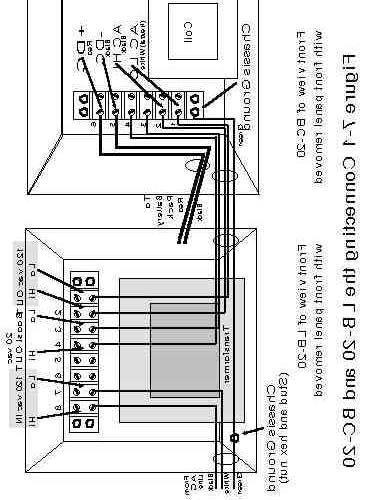
11 terminals of the terminal block shown in Figure 2-1. These two terminals are labeled "1" and "2" with metal numbers on the printed circuit board. The resistor can be inserted with either lead in either terminal. 6. If you are also connecting input and output wiring, then proceed to the next section without reassembling the BC-20. Otherwise, carefully reposition the front panel and reinstall the sixteen screws removed previously. This completes the configuration procedure. If the battery voltage or vehicle are ever changed, this procedure must be repeated. We suggest saving the small envelope of unused resistors inside the BC-20 so that they do not become lost. Connecting AC Input and DC Output Wires When first installing the BC-20 in your vehicle, or if changing the installation, it will be necessary to connect AC input and DC output wires. This section explains how to make those connections. WARNING!!! Be sure that both AC input and DC output wires are DISCONNECTED from the outlet and battery before opening the BC-20!!! Potentially lethal voltages are present inside the BC-20 from both the AC input and the DC load!!! 1. Set the BC-20 upright with the front panel facing you. 2. Remove the sixteen screws from around the edge of the front panel and gently let the front panel rest on its face. (Resting the panel on a soft cloth will prevent marring its finish). 3. Referring to Figure 2-2, locate the terminal block on the rear inside wall of the chassis. A number label adjacent to the terminal block identifies each screw of the terminal block. NOTE: There should be a jumper connecting terminals #3 and #4 together. Do not remove this jumper unless you are using an LB-20 Line Booster (refer to Section 7). 8
12 9
13 10
14 4. Insert the AC input cable through the cable bushing marked "120 VAC INPUT" on the right side of the BC-20. Terminate each wire with a lug sized to fit the #8 screw of the terminal block. CAUTION: Terminal lugs must be properly and securely crimped onto wires. Because of the high current being carried by these lugs, an inadequate or improper crimp will eventually lead to overheating of the joint. Failure will soon follow, often with severe damage spreading beyond the immediate crimp joint. 5. To the terminal block screw marked "2", connect the HI side AC input wire (normally a BLACK wire). 12 gauge wire is recommended; 10 gauge is preferred. 6. Similarly, to the terminal block screw marked "1" connect the LO side AC input wire (normally a WHITE wire). WARNING: Recheck that the DC output leads are DISCONNECTED from the battery before continuing with installation! 7. Insert the DC charger output cable through the cable bushing marked "CHARGER OUTPUT" on the right side of the BC-20. Terminate each wire with a lug sized to fit the #8 screw of the terminal block. 8. To the terminal block screw marked "6", connect the POSITIVE wire to your battery (normally a RED wire). 12 gauge wire is recommended; 10 gauge is preferred.. 9. Similarly, to the terminal block screw marked "5" connect the NEGATIVE wire (normally a BLACK wire). 10. Referring to Figure 2-2, loosen the terminal block mounting nut indicated. Install the AC primary power safety ground wire lug (normally a GREEN wire) under the nut, and retighten the nut over the lug. 11. Double check the connections carefully! If wires are accidentally misconnected, serious damage to the BC-20 can result! 12. Carefully reposition the front panel and reinstall the sixteen screws removed previously. This completes the cabling procedure. If the cabling is ever changed, this procedure must be repeated. This completes the installation of the BC
15 SECTION 3 - Operation of the BC-20 The following sequence of simple adjustments will set your BC-20 to safely and consistently charge your vehicle's battery. Normally, these adjustments need only be made one time and not changed. The BC-20 will hold those adjustments until such time as you change them. However, the float voltage may eventually have to be readjusted slightly to compensate for the aging of the battery pack. The setup and operating instructions for the BC-20 assume that you have correctly installed the BC-20 per Section 2. If not, refer to Section 2 before operating. Refer to Figure 3-1 for location of front panel controls. Setting the charging current and float voltage assumes that you know the specifications of your vehicle's battery pack. The battery voltage, maximum charging current, and float voltage are critical parameters; be sure you know what they are! If in doubt, look them up! Don't guess, or you may reduce the life of an expensive set of batteries! The two adjustments that must be made are the charging current and the float voltage. The charging current must be set with the battery in a partially discharged state, while the float voltage should be set with the battery "peaked" to full charge. The normal range of float voltage for most batteries is 2.33 to 2.5 VDC per cell. Setting the float voltage is more critical if the battery is to be left on charge for several days. If the battery is being charged only overnight, then the float voltage is not as critical. The BC-20 will provide a float voltage of 2.5 VDC at its MAX setting. Thus the float adjustment may be set to MAX without risk for overnight charging, if you are unsure of your battery's float voltage. 12
16 13
17 There are three steps to adjusting the BC-20 for operation with your vehicle: STEP 1 - Determine the charge state of the battery. A. With NO AC primary power applied, set the front panel CURRENT adjustment to MIN (fully counterclockwise) and the front panel VOLTAGE adjustment to MAX (fully clockwise). B. Connect the BC-20 to AC primary power. Observe that the green light on the front panel is lit, indicating that AC power is present, and that the GFI light is out. If necessary, press the R (reset) button on the GFI. If necessary, also push in the AC circuit breaker front panel button to reset it. Refer to Section 4 in case of difficulty. C. Rotate the front panel CURRENT adjustment approximately half-way toward MAX. Observe the ammeter and note one of the two following conditions: 1. The ammeter shows a current of approximately 2-5 amperes. The battery is at least partially discharged. Proceed to Step 2 to set charging current. 2. The ammeter shows only 1-2 amperes of current. The battery is fully charged, or "peaked". Proceed to Step 3 to set float voltage. STEP 2 - Set the charging current. A. With NO AC primary power applied, set the front panel CURRENT adjustment to MIN (counterclockwise). (NOTE: the VOLTAGE adjustment was set to MAX in Step 1A; do not change it). B. Connect the BC-20 to AC primary power. Observe that the green light on the front panel is lit indicating that AC power is present, and that the GFI light is out. If necessary, press the R (reset) button on the GFI. If necessary, also push in the AC circuit breaker front panel button to reset it. Refer to Section 4 in case of difficulty. C. Rotate the front panel CURRENT adjustment slowly toward MAX (clockwise) until the front panel ammeter reads the desired charge current. DO NOT EXCEED 20 AMPS ACTUAL CHARGING CURRENT! 14
18 STEP 3 - Set the float voltage. NOTE: The battery usually must be charged to peak it before setting the float voltage. Fifteen minutes of additional charging time is usually sufficient once the battery has been brought up to full charge. When the charge current drops to 1-2 amperes with the voltage front panel set to MAX, the battery pack is peaked. A. With NO AC primary power applied, set the front panel VOLTAGE adjustment to MAX (fully clockwise). B. Connect the BC-20 to AC primary power. Observe that the green light on the front panel is lit indicating that AC power is present, and that the GFI light is out. If necessary, press the R (reset) button on the GFI. If necessary, also push in the AC circuit breaker front panel button to reset it. Refer to Section 4 in case of difficulty. C. Slowly rotate the front panel VOLTAGE control counterclockwise until the desired float voltage is reached. Use an external meter to set float voltage. Alternatively, adjust the VOLTAGE to achieve the desired charging current in the float condition. The float charging current will normally be set lower for extended charging than for overnight charging. This completes adjustment of the BC-20 for your vehicle battery. Testing the Ground Fault Interrupter (GFI) The GFI on the BC-20 should be tested periodically. A monthly test is recommended. CAUTION: DO NOT test the GFI at full charging current. Testing the GFI trip at full charging current will eventually result in burned and/or pitted GFI contacts, shortening the life of the GFI. 15
19 SECTION 4 - Troubleshooting This section contains some helpful advice in case the BC-20 does not function properly. It consists of a table of symptoms, probable causes, and things to check. Symptom Green light not lit GFI light is on (tripped) Green light on, no DC out1. Unit "hums"/"buzzes" Cannot set float voltage No longer maintains float voltage Check 1. Is primary power outlet "hot"? 2. Is AC breaker tripped? (Press to reset) 3. Is GFI tripped? (Press "Reset") 4. Is charger plugged in? 5. Is AC wired to BC-20 correctly? 1. Push "R" button to reset. 2. Disconnect DC outputs, then try reset. 3. There is a leakage to ground: - May be dirt on battery. - DC lead short or leakage path. - Motor or controller short or leakage path. Verify battery is connected. 2. Verify adjustments (Section 2). 3. Verify DC fuse is not blown. 4. Battery may have an open cell. 5. If charger has been operating, problem may be overheat shutdown. Let cool, should resume charging. 6. Verify fan is running and not obstructed. 1. Normal for coil to "buzz"/"hum". 2. Normal for blower to "hum". 1. Verify correct resistor installed for the voltage of your battery pack. 1. One end of voltage-select resistor may have come loose from its terminal block. 2. Voltage-select resistor may have "opened". If you still experience difficulty in getting your BC-20 charger to operate properly after performing the above checks, please contact the distributor from whom you purchased the charger or contact K&W directly for further assistance. Section 6 explains how to get in contact with K&W. 16
20 SECTION 5 - Theory of Operation This section provides a brief functional description of how the BC-20 operates. No detailed schematic diagrams or parts lists are included in this manual because K&W is concerned for the user's safety in attempting to perform repair work on a system that is not isolated from the AC line, and hence has lethal voltages exposed inside. Figure 5-1 shows a functional block diagram of the BC-20. The AC primary power is applied through the Ground Fault Interrupter (GFI), which removes AC power in the event of a short or leakage path to ground from either side of the AC line input. This is primarily for user safety. The output of the GFI is applied to the AC circuit breaker, which protects the primary wiring from damage in the unlikely event of an overload or short circuit failure within the BC- 20 circuits. AC primary power is then applied through a smoothing choke to a triac in the AC HI side, and then to a full-wave bridge rectifier. The choke serves the dual purposes of reducing the magnitude of current peaks to minimize heating effects, and of suppressing the generation of Radio Frequency Interference (RFI) by preventing abrupt changes (step changes) in the current flowing through the BC-20 charger. The output of the rectifier is applied through the DC output fuse to the battery. The fuse protects the BC-20 from short circuits or excessive charging current. The control circuits contained on the printed circuit board measure the charging current and voltage every half cycle of AC power (120 Hertz rate, or every 8.3 milliseconds) and fire the triac at the proper phase angle to provide the user-set charging current and float voltage. The control circuits also include an overheat sensor/shutdown circuit and a temperature compensation circuit that automatically increases the charging voltage at low temperatures, and decreases it at high temperatures. Refer to Figure 1-1 for a graph of the voltage/temperature compensation curve. The pulsed charging current can be viewed as consisting of two superimposed waveforms: a steady-state DC current plus an AC current. The DC component is the average value of the complex output current waveform, and is the current indicated by the ammeter. This DC component is also the actual charging current. The AC component, which has an average DC value of zero amperes, does not contribute to ammeter deflection or battery charging. It does, however, generate heat in resistive elements such as wiring, switches, fuses, etc. This heating is in addition to the heating caused by the DC component of the current. The value of the composite current can be measured by a true RMS ammeter in line with the AC input. The true RMS current will be approximately 50% greater than the DC output charging current. 17
21 18
22 Very little of the difference between the input RMS and output DC currents represents lost power. Instead, it shows up as a reduction in the power factor of the charger-battery pack combination. A power factor of less than 1.00 indicates that the input current and voltage waveforms are not in phase. This will be obvious when considering how the BC-20 charger regulates charging rate. For each halfcycle of the AC input, charging current will be applied to the battery pack only when the triac is fired. This typically occurs approximately half way (about 90 electrical degrees) through each half cycle at normal load (later for lower charging currents). Thus it can be seen that the input current waveform lags the input voltage waveform. The significance of this discussion of DC and AC currents is that the AC circuit used to power the BC-20 requires fuses and circuit breakers rated at least 50% above the maximum intended charging current, but not exceeding the amperage the circuit is rated for. SECTION 6 - Getting in Contact with K&W Engineering In case of questions or difficulties with your BC-20 charger, please feel free to contact K&W via mail or telephone. The address and numbers are: K&W Engineering, Inc County Home Road Marion, Iowa Telephone:
23 SECTION 7 - Use of the Optional LB-20 Line Booster for 120 VDC Battery Packs In order to charge a 120 VDC battery pack, more primary input voltage than the normal 120 VAC line voltage is required. The LB-20 is a Line Booster that increases the input voltage to the BC-20 by 20 VAC so that it can charge a 120 VDC battery pack. The LB-20 will handle the maximum 20 ampere charging current of the BC-20. It consists of a transformer whose isolated secondary provides a 20 VAC voltage which is connected in series with the primary input voltage to the BC-20 just before the coil, thus raising the BC-20 input voltage to 140 VAC. The LB-20 has its own AC circuit breaker to protect against short circuit damage to primary power wiring. The LB-20 also supplies 120 VAC line voltage to the BC-20 to power the GFI, fan, and control board. Vehicle Mounting Considerations Like the BC-20, the LB-20 is designed to be permanently mounted in electric vehicles. Thanks to its light weight and very compact size, it is easily mounted in most electric vehicles along with the BC-20. The following information and hints are intended to assist you in obtaining a long, reliable service life from the LB-20. Mounting provisions - The LB-20 is supplied with four 1/4-20 threaded inserts on the rear surface, and four more 1/4-20 threaded inserts on the bottom surface. Any combination of these inserts may be used with usersupplied 1/4-20 bolts to affix the LB-20 to the desired location. A minimum of four bolts is required. The case fasteners are self-locking, so lock washers are not necessary. The vehicle mounting brackets or mounting surface should be true so that the LB-20 chassis will not be distorted when the bolts are tightened. Mounting considerations -- The LB-20 is not waterproof, so it must be located in an area free from rain and splashed water. -- The LB-20 requires no special cooling considerations (unlike the BC- 20) because it dissipates very little power. -- The LB-20 should be located and oriented so that the front panel circuit breaker is easily accessible. -- Cable routes for the AC input power and AC output power connections to the BC-20 should exit from the left end of the LB The LB-20 is normally mounted next to the BC-20 to minimize the 20
24 wiring length between the two units. Supplying Primary 120 VAC Power The LB-20 is designed to operate from 120 VAC house current. Because the LB-20 boosts the input voltage, the charging system will draw more line current than it did without the LB-20. Specifically, the 120 VAC line must supply an additional 4 amperes AC current at full charging current (20 amperes) when used with the LB- 20. The LB-20/BC-20 charging system is a high input current device, similar to a space heater or an air conditioner. The following primary power considerations should be carefully observed to avoid possible damage to the building wiring: -- The wiring used to supply AC current to the LB-20 should be installed in strict accordance with the National Electrical Code (NEC) and all applicable local ordinances. -- The AC circuit used for the LB-20/BC-20 system must have an additional current allowance for the LB-20 booster. Use a 15-20% adjustment factor to ensure the AC supply circuit is adequate for the intended charging current. The following table presents AC supply circuit rating needed versus charging current for the LB-20/BC-20 system: Charging Current Needed Circuit Capacity Wire Size 10 amperes 20 amperes AC # # # #10 -- Because of the high current draw of the LB-20/BC-20 charging system, no other appliances or devices should be connected to the LB-20's AC circuit unless the circuit is rated to carry the extra load. Thanks to the delay start circuit of the BC-20, you will not cause an electrical arc when the LB-20/BC-20 is first plugged into the AC outlet. This important feature prevents connector damage from arcing. 21
25 Connecting AC Input and AC Output Wires When first installing the LB-20 in your vehicle, or if changing the installation, it will be necessary to connect AC input and output wires. This section explains how to make those connections. If this will be the initial installation of the BC-20 in the vehicle, refer to Section 2, Installation, Connecting AC Input and DC Output Wires, Steps 7, 8 and 9, to connect the DC output leads. WARNING!!! Be sure that both AC input and DC output wires are DISCONNECTED from the outlet and battery before opening the LB- 20 or BC-20!!! Potentially lethal voltages are present inside both the LB-20 and BC-20 from both the AC input and the DC load!!! 1. Set the BC-20 upright with the front panel facing you. 2. Remove the sixteen screws from around the edge of the front panel and gently let the front panel rest on its face. (Resting the panel on a soft cloth will prevent marring its finish). 3. Set the LB-20 upright with the front panel facing you. 4. Remove the twelve screws from around the edge of the front panel and gently let the front panel rest on its face. (Resting the panel on a soft cloth will prevent marring its finish). 5. Referring to Figure 7-1, locate the terminal block on the rear inside wall of the BC-20 chassis. Number labels adjacent to the terminal block identify each screw of the terminal block. 6. Insert the AC input and boost wires through the cable bushing marked "120 VAC INPUT" on the right side of the BC-20. Terminate each wire with a lug sized to fit the #8 screw of the terminal block. 7. To the terminal block screw marked "2", connect the HI side AC input wire (normally a BLACK wire). 12 gauge wire is recommended; 10 gauge is preferred. 8. Similarly, to the terminal block screw marked "1" connect the LO side AC input wire (normally a WHITE wire). 9. Remove the jumper between terminals #3 and #4. 22
26 23
27 wire. 10. To the terminal block screw marked "4" connect the BOOST HI input 11. Similarly, to the terminal block screw marked "3" connect the BOOST LO input wire. This completes the BC-20 portion of the wiring. 12. Referring to Figure 7-1, locate the terminal block on the rear inside wall of the LB-20 chassis. Number labels adjacent to the terminal block identify each screw of the terminal block. 13. Insert the AC interconnect wires from the BC-20 through the cable bushing on the left side of the LB-20. Terminate each wire with a lug sized to fit the #8 screw of the terminal block. 14. To the terminal block screw marked "2", connect the HI side AC input wire (normally a BLACK wire). 12 gauge wire is recommended; 10 gauge is preferred. 15. Similarly, to the terminal block screw marked "1" connect the LO side AC input wire (normally a WHITE wire). 16. To the terminal block screw marked "4" connect the BOOST HI input wire. 17. Similarly, to the terminal block screw marked "3" connect the BOOST LO input wire. 18. Insert the AC input cable through the cable bushing on the right side of the LB-20. Terminate each wire with a lug sized to fit the #8 screw of the terminal block. 19. To the terminal block screw marked "8", connect the HI side AC input wire (normally a BLACK wire). 12 gauge wire is recommended; 10 gauge is preferred. 20. Similarly, to the terminal block screw marked "7" connect the LO side AC input wire (normally a WHITE wire). 21. Referring to Figure 7-1, loosen the nut shown for the safety ground. Connect the safety ground wires from both the BC-20 and the AC input under that nut, and tighten securely. This completes the LB-20 portion of the wiring. 22. Double check the connections carefully! If wires are accidentally connected to the wrong terminals, serious damage to the BC-20 may result! 23. Carefully reposition the BC-20 front panel and reinstall the sixteen 24
28 screws removed previously. Similarly, reposition the LB-20 front panel and reinstall the twelve screws removed previously. This completes the cabling procedure. This completes the installation of the LB-20 and BC-20. Operation of the LB-20 No adjustments are required to the LB-20. Simply connect 120 VAC line power to the LB-20 and adjust the BC-20 per section 3. Be sure that the LB-20 circuit breaker button is pushed IN to enable it. Testing the BC-20 Ground Fault Interrupter (GFI) The GFI on the BC-20 should be tested periodically. A monthly test is recommended. CAUTION: DO NOT test the GFI at full charging current. Testing the GFI trip at full charging current will eventually result in burned and/or pitted GFI contacts, shortening the life of the GFI. Troubleshooting the LB-20 The following symptoms and corrective actions may be of assistance in the unlikely event that you encounter difficulty in getting your LB-20/BC-20 to function properly. Refer also to the BC-20 Troubleshooting section. Symptom BC-20 cannot be adjusted for desired charging current Check 1. Is correct range resistor installed? 2. Verify that LB-20 terminals 3 and 4 or BC-20 terminals 3 and 4 are not reversed. 3. Recheck all interconnect wiring after first removing AC power! Circuit breaker trips 1. Is correct range resistor installed? 2. Was CURRENT control set to MIN before initial turn-on? 25
29 K&W Engineering Limited Warranty K&W Engineering Inc. warrants the Model BC-20 battery charger to be free from defects in material and workmanship for a period of one year (12 months) from the date of retail purchase. Warranty coverage does not extend to units which, in the judgment of K&W Engineering, have been subject to physical or electrical abuse, including damage from improper connections, improper wiring, improper installation, user modifications, and/or attempted repair (there are no user serviceable components inside the BC-20 Battery Charger). "Proper" connections, wiring, and installation shall be as defined in the Instruction Manual for the BC-20. For service/repair, whether in warranty or out of warranty, contact the dealer from which you purchased the unit or K&W Engineering directly. You will be given instructions for shipping the unit prepaid to your dealer or direct to K&W Engineering. Units in warranty, subject to the preceding qualifications, will be repaired and/or replaced, at the discretion of K&W Engineering, and returned to you prepaid. Proof of purchase date (i.e., copy of sales receipt, invoice, etc.), is required. Units no longer under warranty will be diagnosed, and a repair cost estimate provided to you. No repairs will be done without authorization based on that estimate. If repairs are declined, you will be billed $20.00 for the service estimate, and the unit will be returned to you prepaid. 26
The Da-Lite Difference.
 The Da-Lite Difference. Instruction Book for Boardroom Electrol DA-LITE SCREEN COMPANY, INC. 3100 North Detroit Street Post Office Box 137 Warsaw, Indiana 46581-0137 Phone: 574-267-8101 800-622-3737 Fax:
The POWER. In PRESENTATION PRODUCTS. Instruction Book for BOARDROOM ELECTROL DA-LITE SCREEN COMPANY, INC.
 The POWER In PRESENTATION PRODUCTS Instruction Book for BOARDROOM ELECTROL DA-LITE SCREEN COMPANY, INC. 3100 North Detroit Street Post Office Box 137 Warsaw, Indiana 46581-0137 Phone: 574-267-8101 800-622-3737
Matrix APAX. 380V-415V 50Hz TECHNICAL REFERENCE MANUAL
 Matrix APAX 380V-415V 50Hz TECHNICAL REFERENCE MANUAL WARNING High Voltage! Only a qualified electrician can carry out the electrical installation of this filter. Quick Reference ❶ Performance Data Pages
SCR Power Controllers
 SCR Power Controllers Instruction Manual SCR POWER CONTROLLERS TABLE OF CONTENTS General Description and Specifications...1 Firing Modes....2 Installation and Wiring...4 Operation...9 Troubleshooting...15
SHORT-STOP. Electronic Motor Brake Type G. Instructions and Setup Manual
 Electronic Motor Brake Type G Instructions and Setup Manual Table of Contents Table of Contents Electronic Motor Brake Type G... 1 1. INTRODUCTION... 2 2. DESCRIPTION AND APPLICATIONS... 2 3. SAFETY NOTES...
QSSE, QSSEX INDUSTRIAL Battery Chargers
 C O R P O R A T IO N O P E R A T I N G I N S T R U C T I O N S QSSE, QSSEX INDUSTRIAL Battery Chargers INTRODUCTION The QSE line are electronically controlled float chargers. The batteries are brought
GSL Electronics Modified Sine Wave Power Inverters
 GSL Electronics Modified Sine Wave Power Inverters Congratulations on choosing one of our Modified Sine Wave Inverters for your application. There are 6 models in the range, which will meet most of your
Owner s Manual. PowerVerterDC-to-AC Inverter
 Owner s Manual PowerVerterDC-to-AC Inverter Model: PV700HF Input V DC Output 0V, 60Hz AC Reliable AC Power Wherever You Need It Congratulations! You've purchased a high-quality Inverter designed to function
REFERENCE MANUAL FORM: MX-TRM-E REL REV MTE
 Matrix APAX 380V-415V 50Hz TECHNICAL REFERENCE MANUAL FORM: MX-TRM-E REL. September 2014 REV. 002 2014 MTE Corporation WARNING High Voltage! Only a qualified electrician can carry out the electrical installation
A1P OPERATING MANUAL
 A1P OPERATING MANUAL TABLE OF CONTENTS Introduction... p. 2 Features... p. 2 Description... p. 3 Theory of Operation... p. 3 Installation... p. 4 Electrical Connections... p. 5 Options... p. 6 Warranty...
INSTRUCTION MANUAL FOR VOLTAGE REGULATOR APR P/N
 INSTRUCTION MANUAL FOR VOLTAGE REGULATOR APR 125-5 P/N 9168800100 Publication: 9168800990 Revision: J 03/09 INTRODUCTION This instruction manual provides information about the operation and installation
OBE, OBEXU, ON BOARD Battery Chargers
 C O R P O R A T IO N O P E R A T I N G I N S T R U C T I O N S OBE, OBEXU, ON BOARD Battery Chargers INTRODUCTION: These chargers are designed for the permanent installation on battery powered vehicles
MODEL ELC-12/40-CVM-D BATTERY CHARGER
 NATIONAL RAILWAY SUPPLY MODEL ELC-12/40-CVM-D BATTERY CHARGER Installing, Operating and Service Instructions for the ELC-12/40-CVM-D Solid State Charger PLEASE SAVE THESE IMPORTANT SAFETY AND OPERATING
Installation and Maintenance Instructions. World Leader in Modular Torque Limiters. PTM-4 Load Monitor
 World Leader in Modular Torque Limiters Installation and Maintenance Instructions PTM-4 Load Monitor 1304 Twin Oaks Street Wichita Falls, Texas 76302 (940) 723-7800 Fax: (940) 723-7888 E-mail: sales@brunelcorp.com
BRAVO Inverter/Battery Charger. Table of Contents
 BRAVO 1050 Inverter/Battery Charger Table of Contents Introduction... 2 General Description... 2 Specifications... 3 Installation: Hardwire Units... 4 Operation: Hardwire Units... 5-6 Installation: GFCI
Manual Installation & Operation
 Manual Installation & Operation Model: NCxxLxx 12A or 30A Solid State Solar Charging Regulator and 12A Load Controller. 231 Patent #: 5,642,030 Applies Page 1 Warnings When Installing, connect grounds,
Art. No. EC-315. Art. No. EC-330. Art. No. EC-340 SWITCH-MODE BATTTERY CHARGER CONTENTS IMPORTANT SAFETY PRECAUTIONS... 2
 SWITCH-MODE BATTTERY CHARGER CONTENTS IMPORTANT SAFETY PRECAUTIONS... 2 DESCRIPTION AND FEATURES... 3 CHARGING STAGES... 4 Art. No. EC-315 Art. No. EC-330 Art. No. EC-340 PROTECTIONS... 5 INSTALLATION...
Maintenance Manual 13 AMPERE POWER SUPPLY 19A704647P1-P3. Mobile Communications LBI-31801C
 C Mobile Communications 13 AMPERE POWER SUPPLY 19A704647P1-P3 CAUTION THESE SERVICING INSTRUCTIONS ARE FOR USE BY QUALI- FIED PERSONNEL ONLY. TO AVOID ELECTRIC SHOCK DO NOT PERFORM ANY SERVICING OTHER
The Da-Lite Difference.
 The Da-Lite Difference. Instruction Book for Large Advantage Electrol DA-LITE SCREEN COMPANY, INC. 3100 North Detroit Street Post Office Box 137 Warsaw, Indiana 46581-0137 Phone: 574-267-8101 800-622-3737
C.E. Niehoff & Co. N1601, N1602, N1603, and N1604 Alternator Troubleshooting Guide NOTICE. Hazard Definitions. Battery Charge Volt and Amp Values
 C.E. Niehoff & Co. N1601, N1602, N1603, and N1604 Alternator Troubleshooting Guide Hazard Definitions These terms are used to bring attention to presence of hazard(s) of various risk levels or to important
HQST 500W (12V) HQST 1000W (12V) Modified Sine Wave Inverter. User Manual
 HQST 1000W (12V) Modified Sine Wave Inverter. User Manual") HQST 500W (12V) HQST 1000W (12V) Modified Sine Wave Inverter User Manual Important Safety Instructions Please read the installation and operating instructions in this manual carefully before using your
HQST 500W (12V) HQST 1000W (12V) Modified Sine Wave Inverter User Manual Important Safety Instructions Please read the installation and operating instructions in this manual carefully before using your
LESTRONIC II BATTERY CHARGER TAYLOR-DUNN MODEL TYPE 24LC25-8ET
 LESTRONIC II BATTERY CHARGER TAYLOR-DUNN 79-301-10 MODEL 13110-32 TYPE 24LC25-8ET AC Supply: DC Output: Battery Capacity: Specifications 120 volts, 60 Hertz, single-phase 24 volts, 32 amps Use only on
BAK1500 INSTALLATION/OWNER'S MANUAL Compact Amplified Subwoofer
 BAK1500 INSTALLATION/OWNER'S MANUAL Compact Amplified Subwoofer PREPARATION Getting Started Thank you for purchasing the Dual BAK1500 compact amplified subwoofer. Although Dual has attempted to ensure
24/3000H-3PH 24/4500H-3PH 24/6000H-3PH
 Manufacturer of Dimensions TM Inverters 4467 White Bear Parkway St. Paul, MN 55110 Phone: 651-653-7000 Fax: 651-653-7600 E-mail: inverterinfo@sensata.com Web: www.dimensions.sensata.com 120015D OWNERS
GP-1000 Inverter. Go Power! Electric Inc. PO Box 6033 Victoria, BC V8P 5L4 Tel: Fax:
 Go Power! Manual GP-1000 Inverter Go Power! Electric Inc. PO Box 6033 Victoria, BC V8P 5L4 Tel: 866-247-6527 Fax: 866-607-6527 Email: info@gpelectric.com Table of Contents 1. INTRODUCTION 3 2. SPECIFICATIONS
AUTO CHARGE 4000 MODEL #: AUTOMATIC DUAL OUTPUT BATTERY CHARGER INSTRUCTION MANUAL. Ph: Fax:
 INSTRUCTION MANUAL AUTO CHARGE 4000 AUTOMATIC DUAL OUTPUT BATTERY CHARGER MODEL #: 091-89-12 INPUT: 120 Volt, 50/60 Hz, 8 Amps OUTPUT BATTERY CHARGER: 40 Amps OUTPUT BATTERY SAVER: 5 Amps File: IM_091-89-12_reve.indd
Valcom Failsafe Unit. 1620ESv2 SERIES. Operation and Maintenance Manual
 Valcom Failsafe Unit 1620ESv2 SERIES Operation and Maintenance Manual Table of Contents Section Title Page 1. - Introduction.. 2. - Unpacking the Failsafe unit. 3. - Installation 3.1 - Auto / Timed UPS
TBX10A INSTALLATION/OWNER'S MANUAL 10" Sealed Enclosure with Built-in Amplifier
 TBX10A INSTALLATION/OWNER'S MANUAL 10" Sealed Enclosure with Built-in Amplifier Getting Started Thank you for purchasing the Dual TBX10A 10" ported enclosure with built-in amplifier. Although Dual has
C.E. Niehoff & Co. C653/C653A and C625 Alternators Troubleshooting Guide NOTICE. Hazard Definitions. Battery Charge Volt and Amp Values
 C.E. Niehoff & Co. C653/C653A and C625 Alternators Troubleshooting Guide Hazard Definitions These terms are used to bring attention to presence of hazards of various risk levels or to important information
OWNER S MANUAL POWER INVERTER
 OWNER S MANUAL POWER INVERTER PINV4 PINV5 PINV6 PINV4 600WATT PINV5 800WATT PINV6 1000WATT www.pyleaudio.com INTRODUCTION Thank you for purchasing the PYLE View DC to AC Power Inverter. The PINV4/PINV5/PINV6
Go Power! Manual. GP-1750HD Inverter GP-2500 Inverter
 Go Power! Manual GP-1750HD Inverter GP-2500 Inverter Go Power! Electric Inc. PO Box 6033 Victoria, BC V8P 5L4 Tel: 866-247-6527 Fax: 866-607-6527 Email: info@gpelectric.com Table of Contents 1. INTRODUCTION...
ST Charger. Industrial Battery Charger
 ST Charger Industrial Battery Charger Installation and Operation Manual ST_13 Table of Contents Pg# 1.0 INSTALLATION 1 1.1 Receiving 1 1.2 Location 1 1.3 Line Voltage 1 1.4 A.C. Service Requirements 2
PROwatt 150 DC to AC Power Inverter. Owner s Guide
 PROwatt 150 DC to AC Power Inverter Owner s Guide About Xantrex Xantrex Technology Inc. is a world-leading supplier of advanced power electronics and controls with products from 50 watts mobile units to
Variable Regulated Voltage Power Supply Instruction Manual Model XP-605 / XP-752A
 Variable Regulated Voltage Power Supply Instruction Manual Model XP-605 / XP-752A Copyright Elenco Electronics, Inc. REV-D DC POWER SUPPLY 1 2 4 5 CURRENT VOLTAGE 13 3 6 C.C. C.V. 7 FINE COARSE FINE COARSE
ENGINE GOVERNING SYSTEMS LSM672 LOAD SHARING MODULE. GOVERNORS AMERICA CORP. 720 Silver Street Agawam, MA , USA MEMBER
 ENGINE GOVERNING SYSTEMS LSM672 LOAD SHARING MODULE MEMBER GOVERNORS AMERICA CORP. 720 Silver Street Agawam, MA 01001-2907, USA LSM672 LOAD SHARING MODULE PRODUCT TECHNICAL INFORMATION PTI 4000 AUGUST
ADI-125/750 ADI-125/1500 ADI-125/2500
 Manufacturer of Dimensions TM Inverters 4467 White Bear Parkway St. Paul, MN 55110 Phone: 651-653-7000 Fax: 651-653-7600 E-mail: inverterinfo@sensata.com Web: www.dimensions.sensata.com 121094B OWNERS
.3 Section Waste Management and Disposal.
 Issued 2005/06/01 Section 16261 Uninterruptible Power Systems Static Page 1 of 10 PART 1 GENERAL 1.1 RELATED SECTIONS.1 Section 01330 Submittal Procedures..2 Section 01780 Closeout Submittals..3 Section
INSTRUCTION MANUAL FOR. VOLTAGE REGULATOR Model: APR Part Number:
 INSTRUCTION MANUAL FOR VOLTAGE REGULATOR Model: APR 125-5 Part Number: 9 1688 00 100 Publication Number: 9 1688 00 990 Revision H: 07/2001 CONTENTS SECTION 1 GENERAL INFORMATION...1-1 DESCRIPTION... 1-1
The Da-Lite Difference.
 The Da-Lite Difference. Instruction Book for tensioned Advantage Electrol DA-LITE SCREEN COMPANY, INC. 3100 North Detroit Street Post Office Box 137 Warsaw, Indiana 46581-0137 Phone: 574-267-8101 800-622-3737
Sinergex. PureWatts Elite 150. User's Manual. Sinergex Technologies L.L.C. (USA) Website:
 Website:") Sinergex PureWatts Elite 150 User's Manual Sinergex Technologies L.L.C. (USA) Website: www.sinergex.com Email: info@sinergex.com WELCOME Thank you for purchasing a Sinergex PureWatts Elite 150 power inverter.
Sinergex PureWatts Elite 150 User's Manual Sinergex Technologies L.L.C. (USA) Website: www.sinergex.com Email: info@sinergex.com WELCOME Thank you for purchasing a Sinergex PureWatts Elite 150 power inverter.
OWNERS MANUAL JANUARY 2007 ISO
 Manufacturer of Dimensions TM Inverters 4467 White Bear Parkway St. Paul, MN 55110 Phone: 651-653-7000 Fax: 651-653-7600 E-mail: inverterinfo@sensata.com Web: www.dimensions.sensata.com 121231B OWNERS
OWNER S MANUAL Please read this manual before operating your power supply
 AC-DC POWER SUPPLY Switch Mode AC-DC Power Supply Model No. PSU-1210 PSU-1223 PSU-1230 OWNER S MANUAL Please read this manual before operating your power supply Table of Contents Precautions 2 Description
MIL-24/2600Q MIL-24/3200DQ
 Manufacturer of Dimensions TM Inverters 4467 White Bear Parkway St. Paul, MN 55110 Phone: 651-653-7000 Fax: 651-653-7600 E-mail: inverterinfo@sensata.com Web: www.dimensions.sensata.com 121473B OWNER'S
Dimensions 12/800N 12/1200N D. DC to AC Power Inverters. OWNERS MANUAL for Models: OWNERS MANUAL April ISO 9001:2000 Certified Company
 Manufacturer of Dimensions Inverters 4467 White Bear Parkway St. Paul, MN 55110 Phone: 651-653-7000 Fax: 651-653-7600 E-mail: inverterinfo@sensata.com Web: www.dimensions.sensata.com OWNERS MANUAL April
MODEL ELC-12/60-D BATTERY CHARGER
 *32198* NATIONAL RAILWAY SUPPLY Installing, Operating and Service Instructions for the 12/60 Solid State Charger MODEL ELC-12/60-D BATTERY CHARGER PLEASE SAVE THESE IMPORTANT SAFETY AND OPERATING INSTRUCTIONS
PUMP PLUS 2000 PLC MODEL #: PP AUTOMATIC DUAL OUTPUT BATTERY CHARGER INSTRUCTION MANUAL
 INSTRUCTION MANUAL PUMP PLUS 2000 PLC AUTOMATIC DUAL OUTPUT BATTERY CHARGER Supplied with Dual Bar Graph Display MODEL #: 091-237-12-PP INPUT: 120 Volt, 60 Hz, 3.5 Amps OUTPUT BATTERY 1 and 2: 15 or 18
G203V / G213V MANUAL STEP MOTOR DRIVE
 G203V / G213V MANUAL STEP MOTOR DRIVE PRODUCT DIMENSIONS PHYSICAL AND ELECTRICAL RATINGS Minimum Maximum Units Supply Voltage 18 80 VDC Motor Current 0 7 A Power Dissipation 1 13 W Short Circuit Trip 10
LC BATTERY CHARGER OPERATION & MAINTENANCE GUIDE
 LC BATTERY CHARGER OPERATION & MAINTENANCE GUIDE SENS part number: 101194 Document revision: D DCN number: 105128 Date: 3/23/2006 1840 Industrial Circle Longmont, CO 80501 Fax: 303-678-7504 Tel: 303-678-7500
XS400 Load Bank. Read all instructions before using the load bank. Contents
 Read all instructions before using the load bank Contents 1) Components... 3 Total Assembly... 3 2) Specifications... 4 3) Receiving... 4 4) Safety... 5 a) Grounding cam... 6 b) Power connections... 6
MODEL 6010A 6 12 VOLT BATTERY CHARGER ASSOCIATE
 MODEL 600A 6 VOLT BATTERY CHARGER ASSOCIATE IMPORTANT SAFETY INSTRUCTIONS. SAVE THESE INSTRUCTIONS. This manual contains important safety and operating instructions for the battery charger you have purchased.
DC to AC Power Inverters
 Manufacturer of Dimensions TM Inverters 4467 White Bear Parkway St. Paul, MN 55110 Phone: 651-653-7000 Fax: 651-653-7600 E-mail: inverterinfo@sensata.com Web: www.dimensions.sensata.com ISO 9001:2000 Certified
Owner s Manual. PowerVerter PV1000HF, PV1800HF & PV3000HF DC-to-AC Inverters. Contents. Reliable AC Power Wherever You Need It!
 GROUND Owner s Manual PowerVerter PV1000HF, PV100HF & PV000HF DC-to-AC Inverters Input Output 1 VDC 10V, 60 Hz. AC PV1000HF PV100HF PV000HF Reliable AC Power Wherever You Need It! Congratulations! You
MODEL A96 SERIES. 130Vdc Switchmode Utility Rectifier / Battery Charger. Used with LaMarche Power Cage ECN/DATE
 MODEL A96 SERIES 130Vdc Switchmode Utility Rectifier / Battery Charger Used with LaMarche Power Cage CPN112138 ECN/DATE ISSUE DATE: ECN 17010-12/05 106 BRADROCK DRIVE DES PLAINES, IL. 60018-1967 (847)
DC to AC Power Inverters
 Manufacturer of Dimensions TM Inverters 4467 White Bear Parkway St. Paul, MN 55110 Phone: 651-653-7000 Fax: 651-653-7600 E-mail: inverterinfo@sensata.com Web: www.dimensions.sensata.com 121114C OWNERS
ACCUSENSE CHARGE SERIES ON/OFF BOARD FULLY AUTOMATIC BATTERY CHARGER
 ACCUSENSE CHARGE SERIES ON/OFF BOARD FULLY AUTOMATIC BATTERY CHARGER SPECIFICATIONS: *Photo for reference only* Part number 8890439 Mode Select: Selects Battery Type Refer to Section 6. IMPORTANT: READ
PowerOhm Installation Manual for BM R Series Braking Modules
 PowerOhm Installation Manual for BM R Series Braking Modules IMPORTANT: These instructions should be read thoroughly before installation. All warnings and precautions should be observed for both personal
AeroVironment Universal Solar Pump Controllers
 AeroVironment Universal Solar Pump Controllers (Installer s business information to be affixed here.) User Manual Models: USPC-2000 (AV Part Number 03747-001 Rev. D) USPC-5000 (AV Part Number 03747-002
Manufacturing of: Vehicle Mounted Generators Hydraulic Generators
 Setting the Standard in Mobile Power Instruction Manual for Model HYDRO ARC-S-6500 JSBC Hydraulic Generator Welder Manufacturing of: Vehicle Mounted Generators Hydraulic Generators P.O. Box 582 Chester,
Inverter User Manual
 Inverter User Manual -------------for standard model DC TO AC Power Inverter CONTENTS Safety First 1. Introduction 2. Installation Guidelines 3. Using the inverter 4. Troubleshooting 5. Specifications
AIR COOLED RECTIFIER SPECIFICATION S-50-A
 SPECIFICATIONS AIR COOLED RECTIFIER Spec50a1 5JAN1999 SPECIFICATION S-50-A HIGH VOLTAGE SINGLE TRANSFORMER AIR COOLED RECTIFIER Standard output power range: 250 to 600 volts at 100 to 1,200 amperes TECHNICAL
A2P Single Phase Automatic Industrial Battery Charger
 A2P Single Phase Automatic Industrial Battery Charger Featuring 205B Konrad Cres., Markham, ON, L3R 8T9 www.chargers.ca Building Canada s toughest battery chargers for over a century. Congratulations on
dv Sentry TM 208V 600V INSTALLATION GUIDE Quick Reference ❶ How to Install Pages 6 14 ❷ Startup/Troubleshooting Pages WARNING
 dv Sentry TM 208V 600V INSTALLATION GUIDE FORM: DVS-IG-E REL. January 2018 REV. 003 2018 MTE Corporation High Voltage! Only a qualified electrician can carry out the electrical installation of this filter.
600 Amp Battery Jumper with Air Compressor
 Item #2509 600 Amp Battery Jumper with Air Compressor User s manual- Read these instructions before using the unit Features Front LED Worklight Worklight Switch USB Power Ports and on/off Switch 12V DC
Power InverterTM Watt. Continuous. User's Manual. WAGAN Corp. Limited Warranty Registration Form. Item no
 WAGAN Corp. Limited Warranty Registration Form All WAGAN Corporation products are warranted to the original purchaser of this product. Warranty Duration: This product is warranted to the original purchaser
PowerOhm Installation Manual for LG ATV Series Braking Modules
 PowerOhm Installation Manual for LG ATV Series Braking Modules IMPORTANT: These instructions should be read thoroughly before installation. All warnings and precautions should be observed for both personal
DC TO AC POWER INVERTER PWRIC150012W INSTRUCTION MANUAL
 DC TO AC POWER INVERTER PWRIC150012W INSTRUCTION MANUAL SAVE THIS MANUAL You will need the manual for the safety warnings and precautions, assembly instructions, operating and maintenance procedures, parts
BATTERY STARTER/CHARGER MODEL NO: BC125, BC190
 BATTERY STARTER/CHARGER MODEL NO: BC125, BC190 PART NO: 6210125, 6210200 OPERATION & MAINTENANCE INSTRUCTIONS LS0616 INTRODUCTION Thank you for purchasing this CLARKE Battery starter / charger Please read
BLDC SPEED CONTROL INSTRUCTION MANUAL Low voltage Brushless DC control
 BLDC SPEED CONTROL INSTRUCTION MANUAL Low voltage Brushless DC control Phone 712.722.4135 groschopp.com 420 15th St NE, Sioux Center, IA 51250 Toll-Free 800.829.4135 Email sales@groschopp.com FAX 712.722.1445
Electronic Dynamo Regulator INSTRUCTION MANUAL. COPYRIGHT 2015 CLOVER SYSTEMS All Rights Reserved
 DR310 TM Electronic Dynamo Regulator INSTRUCTION MANUAL COPYRIGHT 2015 CLOVER SYSTEMS All Rights Reserved INTRODUCTION The Clover Systems DR310 is an allelectronic voltage and current regulator for dynamos
The POWER. In PRESENTATION PRODUCTS. Instruction Book for COSMOPOLITAN ELECTROL For Sizes Up To 9'x12' DA-LITE SCREEN COMPANY, INC.
 The POWER In PRESENTATION PRODUCTS Instruction Book for COSMOPOLITAN ELECTROL For Sizes Up To 9'x12' DA-LITE SCREEN COMPANY, INC. 3100 North Detroit Street Post Office Box 137 Warsaw, Indiana 46581-0137
REDI-LINE. Rugged, Reliable, DC to AC Power Conversion ELECTRIC GENERATORS USER'S GUIDE. KARAM A.L.
 REDI-LINE ELECTRIC GENERATORS USER'S GUIDE Rugged, Reliable, DC to AC Power Conversion KARAM A.L. www.alternatorstarter.com 1-888-515-2726 REDI-LINE ELECTRIC GENERATOR MODEL INPUT ACTUAL OUTPUT ACTUAL
AUTO CHARGE D PUMP PLUS
 INSTRUCTION MANUAL AUTO CHARGE D PUMP PLUS AUTOMATIC DUAL OUTPUT BATTERY CHARGER Designed Specifically for Vehicles with DDEC ENGINES MODEL #: 091-9-DPP INPUT: 120 Volt, 60 Hz, 8 Amps OUTPUT VEHICLE BATTERY:
High Frequency SineWave Guardian TM
 High Frequency SineWave Guardian TM 380V 480V INSTALLATION GUIDE FORM: SHF-IG-E REL. January 2018 REV. 002 2018 MTE Corporation High Voltage! Only a qualified electrician can carry out the electrical installation
The Power of Reliability INSTRUCTION MANUAL
 The Power of Reliability INSTRUCTION MANUAL SAFETY & WARNINGS Read this manual carefully and understand all Warnings and Cautions before connections are made to the Inverter. If unsure about any aspects
Matrix AP 400V 690V INSTALLATION GUIDE. Quick Reference. ❶ How to Install Pages 6 20 ❷ Startup/Troubleshooting Pages WARNING
 Matrix AP 400V 690V INSTALLATION GUIDE FORM: MAP-IG-E REL. May 2017 REV. 002 2017 MTE Corporation WARNING High Voltage! Only a qualified electrician can carry out the electrical installation of this filter.
Installation Operation Parts
 OWNER S MANUAL BATTERY BACKUP SUMP Installation Operation Parts For further operating, installation or maintenance assistance, Call 98-8-05 PRINTED IN U.S.A. M-8 (/9) RULES FOR SAFE INSTALLATION AND OPERATION
MODEL 2602A-12 3 STAGE AUTOMATIC BATTERY CHARGER OWNER S MANUAL SAVE THESE INSTRUCTIONS
 R A Valley Forge Company MODEL 2602A-12 3 STAGE AUTOMATIC BATTERY CHARGER OWNER S MANUAL SAVE THESE INSTRUCTIONS 1. INTRODUCING THE CHARGER The 2602A-12 is a 3-stage electronic battery charger. Rainproof,
AUTO CHARGE D2 MODEL #: AUTOMATIC TRIPLE OUTPUT BATTERY CHARGER INSTRUCTION MANUAL
 INSTRUCTION MANUAL AUTO CHARGE D2 AUTOMATIC TRIPLE OUTPUT BATTERY CHARGER Designed Specifically for Vehicles with DDEC ENGINES MODEL #: 091-74-12 INPUT: 120 Volt, 60 Hz, 8 Amps OUTPUT VEHICLE BATTERY 1
USER MANUAL Modular Power Pack
 Powercentric Co. The Light Source USER MANUAL Modular Power Pack Model No. MOPO LBP-80 MOPO SCH-108 MOPO SCI-108 MOPO PSS-08 Contents 1 Introduction About the MOPO Powerpack Features Materials List...
AUTO CHARGE 12 HO MODEL #: MODEL #: MODEL #: AUTOMATIC SINGLE OUTPUT BATTERY CHARGER INSTRUCTION MANUAL
 INSTRUCTION MANUAL AUTO CHARGE 12 HO AUTOMATIC SINGLE OUTPUT BATTERY CHARGER MODEL #: 091-170-6 MODEL #: 091-170-12 MODEL #: 091-170-24 File: IM_091-170-xx_revd.indd Rev: D Revised By: MFG Date: 10-23-2013
2603 Battery Pal 3 AMP, 1 2 VOLT BATTERY CHARGER
 R 2603 Battery Pal 3 AMP, 1 2 VOLT BATTERY CHARGER Connections at a glance: The GUEST Battery Pal 2603 is designed to recharge your battery, and extend your battery s life in applications where it is stored
O W N E R ' S M A N U A L
 1500 Watt DC to AC Power Inverter C o n v e r t s 1 2 V D C B a t t e r y P o w e r t o 1 1 0 V A C H o m e P o w e r O W N E R ' S M A N U A L SAVE THESE INSTRUCTIONS The recommended source of power is
TABLE OF CONTENTS. 300 W Mobile Power Outlet SAVE THESE INSTRUCTIONS!
 300 W Mobile Power Outlet 011-1870-6 TECHNICAL SPECIFICATIONS... 3 Safety Information... 4 KEY PARTS diagram... 7 INTENDED USE... 9 Options for connecting devices to the power inverter... 9 Operation...
FC/FCA 12, 24, 32 & 48 VOLT, 6 & 10 AMP BATTERY CHARGER OPERATION & MAINTENANCE GUIDE
 FC/FCA 12, 24, 32 & 48 VOLT, 6 & 10 AMP BATTERY CHARGER OPERATION & MAINTENANCE GUIDE SENS part number: 101037 Document revision: A Engineering change number: 105073 Date: 1/13/2006 1840 Industrial Circle
AUTO CHARGE LPC SERIES
 INSTRUCTION MANUAL FILE: IM_091-206-12_revB REV: B REVISED BY: THN DATE: 09-17-2012 AUTO CHARGE LPC SERIES MODEL #091-206-12 LPC STANDARD DISPLAY INPUT: 115 volt, 50/60 Hz, 13 amps OUTPUT: 80 AMPERES 3
715B CONTROL SERIES. Instruction Manual Line Voltage DC Brushless Motor Control CONTROLS. Phone (317) Fax (317)
 Fax (317)") 715B CONTROL SERIES CONTROLS Instruction Manual Line Voltage DC Brushless Motor Control LT715B (IM-715B-0100) P.O. Box 10 5000 W. 106th Street Zionsville, Indiana 46077 Phone (317) 873-5211 Fax (317) 873-1105
715B CONTROL SERIES CONTROLS Instruction Manual Line Voltage DC Brushless Motor Control LT715B (IM-715B-0100) P.O. Box 10 5000 W. 106th Street Zionsville, Indiana 46077 Phone (317) 873-5211 Fax (317) 873-1105
DC AC POWER INVERTER. LIV 10 / LIV 20 / LIV 30 User Manual
 DC AC POWER INVERTER LIV 10 / LIV 20 / LIV 30 User Manual Save This Manual Please read this manual carefully prior to storage, installation, wiring, operation and maintenance of the Power Inverter. This
INDEX Section Page Number Remarks
 INDEX Section Page Number Remarks Synchronous Alternators 2 4 General Fault Finding Capacitors 5 6 Fault Finding & Testing Diodes,Varistors, EMC capacitors & Recifiers 7 10 Fault Finding & Testing Rotors
ATD-5925 RECHARGEABLE 12 VOLT 18 AMP/HOUR JUMP START WITH BUILT-IN 260 PSI AIR COMPRESSOR OWNERS MANUAL
 ATD-5925 RECHARGEABLE 12 VOLT 18 AMP/HOUR JUMP START WITH BUILT-IN 260 PSI AIR COMPRESSOR OWNERS MANUAL 1000 PEAK AMPS/400 CRANKING AMPS OF STARTING POWER. STARTS CARS, TRUCKS, RV s AND BOATS WITHOUT THE
24 VOLT AUTOMATIC BATTERY CHARGER PART NO
 24 VOLT AUTOMATIC BATTERY CHARGER PART NO. 957732 AC Input: DC Output: Battery Type: Specifications 230 volts, 50 hertz, 3.5 amps, single-phase 24 volts, 20 amps initially tapering to 6 amps 24 volt, 12
PUMP PLUS 1000 PLC MODEL #: PP AUTOMATIC SINGLE OUTPUT BATTERY CHARGER INSTRUCTION MANUAL
 INSTRUCTION MANUAL PUMP PLUS 1000 PLC AUTOMATIC SINGLE OUTPUT BATTERY CHARGER Unit supplied with one of these displays MODEL #: 091-215-12-PP INPUT: 120 Volt, 60 Hz, 3.5 Amps OUTPUT BATTERY 1 and 2: 15
Sofa Slideout Assembly OWNER'S MANUAL. Rev: Page 1 Sofa Slideout Owners Manual
 Sofa Slideout Assembly OWNER'S MANUAL Rev: 06.14.2016 Page 1 Sofa Slideout Owners Manual TABLE OF CONTENTS Warning, Safety, and System Requirement Information 3 Product Information 3 Prior to Operation
TESCO THE EASTERN SPECIALTY COMPANY Date: 05/04/15 Canal Street and Jefferson Avenue Bristol, PA 19007
 Table of Contents DESCRIPTION PAGE 1.1 Cat. 1044A (What it is)... 2 1.2 Selector Switches... 2 1.3 Leads... 2 CURRENT TRANSFORMERS 2.1 Tests... 2 2.2 Function of Catalog 1044A... 3 2.3 Internal C.T. Defects...
OWNER'S MANUAL POWER BOOSTER. Rechargeable 12 Volt DC power supply. Item # Enclose copy of original sales receipt
 120 DAY LIMITED WARRANTY REGISTRATION FORM All NORTHERN TOOL+EQUIPMENT products are warranted to the original purchaser only for 120 days from the date of purchase, to be free of defects in materials and
G213V STEP MOTOR DRIVE REV 7: March 25, 2011
 Thank you for purchasing the G213V drive. The G213V is part of Geckodrive s new generation of CPLD-based microstep drives. It has short-circuit protection for the motor outputs, over-voltage and under-voltage
Name: ACORN Inc. Address: 6450 Kingspointe Parkway, Unit 1, Orlando, Florida, IMPORTANT!
 MANUFACTURER INFORMATION: Name: ACORN Inc. Address: 6450 Kingspointe Parkway, Unit 1, Orlando, Florida, 32819 Helpline: 407 650-0216 IMPORTANT! READ THESE PROCEDURES THOROUGHLY PRIOR TO stair lift INSTALLATION
ACC Series Power Conditioner OPERATION & INSTALLATION MANUAL
 ACC Series Power Conditioner OPERATION & INSTALLATION MANUAL PHASETEC digital power conditioners are designed to safely operate electrical equipment in the harshest power quality environments. With a wide
1000 Watt Power Inverter INSTRUCTION MANUAL HT87112-AUOXY
 1000 Watt Power Inverter INSTRUCTION MANUAL HT87112-AUOXY CONTENTS Warranty 2 Introduction 3 Environmental protection 3 Specifications 3 General safety warnings and instructions 4 Important safety instructions
QPET, QPETXU Battery Chargers
 C O R P O R A T IO N O P E R A T I N G I N S T R U C T I O N S QPET, QPETXU Battery Chargers INTRODUCTION: The QPET line of chargers are designed for general purpose deep cycle batteries. They are an electronically
MODEL NUMBER: MEDIUM DUTY ONBOARD AIR SYSTEM
 MODEL NUMBER: 10003 MEDIUM DUTY ONBOARD AIR SYSTEM IMPORTANT: It is essential that you and any other operator of this product read and understand the contents of this manual before installing and using