PRODUCT SUPPORT & SERVICES SYSTEMS SCAN YOUR AIRCRAFT. Glass cockpit - 600
|
|
|
- Julianna Henderson
- 6 years ago
- Views:
Transcription


1 PRODUCT SUPPORT & SERVICES SYSTEMS SCAN YOUR AIRCRAFT 42 PEC 72 PEC Glass cockpit - 600
2 Introduction Introduction This Systems guide is an essential tool for all ATR flight crews and engineers to learn or review ATR systems operation. To make learning process easier, systems are introduced in a user-friendly and efficient training method, including diagrams and schematics and displays as appropriate. This guide is a comprehensive document that efficiently complements FCOM 1 st part Systems description. Systems are organized as per FCOM chapters, including their ATA classification along with cockpit location. Cockpit panels familiarisation is presented with each relevant system description in a separate annex. This new guide release is intended for training on ATR and A New Avionics Suite ( and ). It presents a generic aircraft not customized to your own aircraft systems. Should you find any discrepancy between Systems guide and your customized ATR operational documentation (AFM, FCOM & QRH), the latter takes precedence. NB: This Systems guide is also available for ATR , not PEC, and A. The Training and Flight Operations support team.
3 Systems 42/ Chapter A. Aircraft general 1. Doors location Cargo door panel Doors panel External lights EXT LT panel Memo panel display Signs panel Internal lighting LT panel ANN LT panel Side panel FLT COMPT LT panel...13 Chapter B. Integrated systems 1. Integrated Modular Avionics (IMA) Multi Function Computer (MFC) Multi Purpose Computer (MPC) Schematic...19 Chapter C. Flight warning system 1. Cockpit colors philosophy FWS description Alert window EMER audio cancel & TO config test Aural alarms...29 Chapter D. Air 1. Pneumatic system Schematic AIR BLEED panel Air conditionning Schematic COMPT TEMP panel Avionics ventilation Schematic AVIONICS VENT panel Pressurization Schematic Cabin pressure indicators AUTO PRESS panel MAN RATE KNOB and CABIN PRESS panel...46 Chapter E. Automatic flight control system 1. Schematic FMA FGCP (Flight Guidance and Control Panel) ICP (Index Control Panel)...56 Chapter F. Communications 1. Schematic PTT selector and NOSE WHEEL STEERING CONTROL SW Audio control panel VHF control AUDIO SEL pb Loudspeaker volume knobs
4 Contents 7. TCAS control box EMER LOC XMTR panel Cabin attendant handset Handmike and handset CALLS panel Head set / boom set / hand mike panels ATC control CVR panel Crew oxygen mask...62 Chapter G. Electrical systems 1. Sources of power DC-AC schematic Normal supply: On ground with battery only Normal Supply: On ground with external power Hotel mode or DC GEN 1 FAULT Normal supply: with two generators on line Emergency supply: In dual DC GEN LOSS with the battery toggle switch on OVRD Emergency supply: In dual DC GEN LOSS with the battery toggle switch on OVRD and second OVRD selected Emergency supply: In dual DC GEN LOSS with TRU DC-AC panel Elec SD ACW schematic ACW panel SD page Breaker panels Overhead panel Electric rack behind F/O...83 Chapter H. Emergency equipment 1. Emergency equipment situation Emergency lighting system First aid kit Crash axe Megaphone Flashing light Life jacket Escape rope Gloves Water extinguisher Halon extinguisher Oxygen schematic Oxygen panel and display Cockpit crew oxygen mask Portable oxygen bottle Passenger oxygen mask Protective breathing equipment...90 Chapter I. Fire protection 1. Schematic Avionics FWD and AFT smoke detection Fire handle EWD (Engine and Warning Display) Condition levers fuel light Compartment smoke panel SD cabin
5 Systems 42/ Chapter J. Flight control 1. Roll schematic Pitch schematic Yaw schematic Gust lock Stick Shaker/Stick Pusher push button and display Spoilers position indicator Pitch trim asym light Trim position indicator Trim controls Flaps schematic Flaps position indicator Flaps control lever Chapter K. Flight instruments 1. Schematic PFD (Primary Fight Display) MFD (Multi Function Display) EWD (Engine and Warning Display) ND - ARC MODE with terrain or weather radar information Source failure alert Switching panel EFCP (control panel) MCP (Multipurpose Control Panel) Weather radar control Primus TAT/SAT indicator CLOCK RCDR panel STBY instruments Airspeed indicator Altimeter Vertical speed indicator and TCAS Chapter L. Fuel system 1. Schematic Electrical fuel pump OFF Starting procedure Normal procedure Cross feed procedure Engine feed jet pump low pressure Low level Engine fire procedure Fuel panel SD Engine Fuel QTY indication XFEED advisory on memo panel display Chapter M. Hydraulic system 1. Schematic SD ACW and hydraulic HYD PWR panel Pressure indication AUX pump pedestal switch Hydraulic on Ramp (only on battery) Hydraulic on Ramp (aux pump P/B selected on the pedestal) Hydraulic system normal operation
6 Contents 9. Hydraulic system failures Hydraulic system crossfeed operation Both main hydraulic pumps loss Both hydraulic systems loss N. Ice and rain protection 1. Schematic Probes and windshield HTG Rain protection Ice detector panel and icing AOA Aircraft Performance Monitoring (APM) De-icing schematic Airframe air bleed FAULT Anti-icing & de-icing panel De-icing/anti-icing indication (memo panel display) O. Landing gear 1. Landing gear description Brakes schematic LDG GEAR position indicators Landing gear handles Brakes temperatureand antiskid Emergency parking brake handle Steering handwheel P. Navigation system 1. Nav control Marker sensibility setting ADF control TAWS alert modes TAWS pb TAWS panel ND OVERLAY FMS Q. Power plant 1. Engine schematic/ Power and propeller controls/ Engine indication ENG START panel/ ENG control panel/ PWR MGT panel/ ATPCS test panel/ Idle gate/ Annexes Annex 1. Cockpit panels Annex 2. Abbreviations
7 A. Aircraft general FCOM


8 Systems 42/ Doors location ATA 52 Cargo door Emergency exit type III Service door / emergency exit type I Pilot emergency hatch Pilot communication hatch Rear entry door / emergency exit type I Aft avionics compartment door Forward avionics access hatch 8

 This red")
9 A. Aircraft general 2. Cargo door panel ATA 52 ARMED light Selector armed green light is ON, when actuator selection switch working conditions are met: cover panel opened door unlocked by operating handle: all hooks are disengaged and FWD latchlock is unfastened LCHD light blue light is ON when all door hooks and latch locks are fully engaged GND HDL light Ground handling bus ON BAT red light is ON when ground handling bus is directly supplied by HOT main bat bus: means that the battery is discharging even if the BAT toggle switch is in OFF position (visible even when the cover panel is closed) This red light is ON when: The refueling panel is open The cargo door control panel is open The passenger door is open and alert, that the battery is discharging before leaving the aircraft Actuator selection switch is used to operate the door (OPEN or CLOSE) when the CARGO DOOR ARMED green light is on Panel cover switch connects the ground handling bus on line when the panel cover is opened and allows operation of cargo door. During the opening, a self test of the MFC 1A and 2A is performed to initiate the control system of the cargo door. CARGO LIGHT switch allows activation of the cargo bay light from outside 3. Doors panel ATA 52 CAB OK and SVCE OK Light on when SW TEST depressed and check microswitches operation UNLK At least 1 micro switch is opened SW TEST Tests continuity of microswitch system (on ground, doors opened) 9


10 Systems 42/ External lights ATA 33 A - Navigation lights B - Taxi and T/O lights C - Landing lights D - Wing lights E - Beacon lights F - Strobe lights G - Logo lights H - Emergency light Cabin panel Memo panel display 10
, ACW BUS 2 (Right Hand) WING Supplied by DC BUS 2 6.")

11 A. Aircraft general 5. EXT LT panel ATA 33 BEACON and NAV supplied by SVCE BUS and BUS 1 LOGO supplied by SVCE BUS TAXI & T.O Supplied by ACW BUS 2 STROBE, LAND supplied by ACW BUS 1 (Left Hand), ACW BUS 2 (Right Hand) WING Supplied by DC BUS 2 6. Memo panel display ATA 33 SEAT BELT displayed in cyan when associated switch is selected ON SEAT BELT displayed in amber crossed when the signal is invalid. NO DEVICE displayed in cyan when associated switch is selected ON NO DEVICE displayed in amber crossed when the signal is invalid. 7. Signs panel ATA 33 NO DEVICE and SEAT BELTS Cyan message on memo panel display when ON. (DC BUS 2) ON emergency exit lights illuminates. Supply: DC STBY or 6 V BAT packs ARM Emergency lights illuminate when <18 V on STBY bus or if both DC GEN off line. Emergency lights extinguish when >20V on STBY bus and at least 1 GEN operating DISARM system deactivated 11


12 Systems 42/ Internal lighting ATA 33 The STORM switch overrides the MIP/PED rotary selector to put in the maximum intensity setting 12
 and pedestal (PED) OVHD rotary selector")


13 A. Aircraft general 9. LT panel ATA 33 MIP / PED Selects activation and intensity of integral lighting of the main instrument panels (MIP) and pedestal (PED) OVHD rotary selector selects activation and intensity of overhead panels integral lighting FLOOD knob selects activation and intensity panel flood lighting. (OFF TO BRT) 10. ANN LT panel ATA 33 To check and control the intensity of: the annunciator lights on the overhead and pedestal panels the overhead panel flow bars TEST: All the associated lights come on bright BRT: associated light illuminate bright DIM: associated light are dimmed 11. Side panel ATA 33 CAPT CONSOLE LT knob selects activation and intensity of the respective lateral console CAPT READING LT knob selects activation and intensity of the respective spot light 12. FLT COMPT LT panel ATA 33 DOME switch BRT: dome lights are supplied with maximum intensity DIM: dome lights are dimmed OFF: both dome are off DOME light: the F/O dome light becomes BRT when the switch in BRT or DIM if: dual DC GEN loss or on ground, with BAT supply only STORM switch On position, it overrides the MIP/ PED rotary selector to put in the maximum intensity setting STBY COMPASS switch to illuminate the STBY COMPASS ON and OFF position 13
14 B. Integrated systems FCOM
15 Systems 42/ Integrated Modular Avionics (IMA) ATA 42 The Integrated Modular Avionic (IMA) provides computation, memory and Input/Output data processing resources, shared between several avionics applications. The Integrated Modular Avionic is mainly composed of the dual Core Avionic Cabinets (CAC 1&2). The term CAC (Core Avionic Cabinet) designs the whole equipment composed of the rack and the set of cards. In the basic configuration, each CAC is composed of: 1 CPM (Core Processing Module) The CPMs provide shared memory and computation resources to execute hosted avionics applications. 1 IOM-S (Input/Output Module) This IO Module is dedicated to provide ARINC and discrete I/O for all functions 1 IOM-AP (Input/Output Module) This IO Module is dedicated to provide discrete and analog I/O for the Auto-Flight application. 2 IOM-DC (Input/Output Module) The IOM-DC provide discrete and analog I/O for Data Concentration Application (DCA). 1 SWM (gateway and SWitch Module) This module is dedicated to connect together CPM and other Avionics Data Network subscribers. The communication means is based on AFDX network, linking network subscribers through SWM. The main applications hosted by the Core Avionic Cabinets are : Flight Warning (FWA) Auto-Flight (AFCA) Centralized Maintenance (CMA) (only on CAC 1) Data Concentration (DCA) The CAC 1 & 2, communicate with five display units and systems through different data bus formats: AFDX: Avionics Full DupleX switched ethernet A429: ARINC 429 Analogic Discretes Two of the five displays units (DU2 and DU4) are dedicated to two other functions: Flight Management Application (FMA) Radio Management Application (RMA) 16
 The purpose of these computers is to: monitor, control, authorise operation of the aircraft systems manage system failures and flight")
16 B. Integrated systems 2. Multi Function Computer (MFC) ATA 31 Numerous logic funtions are performed by two independant computers (MFC1 and MFC2). Each computer includes two independant modules (A and B) The purpose of these computers is to: monitor, control, authorise operation of the aircraft systems manage system failures and flight enveloppe anomalies and command triggering of associated warning OFF The module stops operating The MFC functions can be processed: in one module only in several modules (redundancy) partially in 2 modules FAULT illuminates and the FWS is activated when a malfunction or electrical supply fault is detected. The module automatically becomes inoperative. This light also flashes during self-test of the module. During powering, since all 4 modules are selected ON, the following sequence is executed: MFC 1A and MFC 2A FAULT lights flashing (selftest of these modules) MFC 1A and MFC 2A FAULT lights extinguish. MFC 1B and MFC 2B FAULT lights flashing (selftest of these modules) MFC 1B and MFC 2B FAULT lights extinguish NOTE: If the cargo door control panel is opened, the self test of MFC 1A and 2A are already done, and only the MFC 1B and 2B are tested. (See chapter A.2) Example: SYSTEM FLIGHT CONTROLS FUNCTION STICK PUSHER STALL WARNING MODULE 1A 1B 2A 2B The stick pusher function is integrated in modules 1A, 1B, 2A and 2B. The stall warning function is integrated in modules 1B and 2B. The stick pusher function is available if modules (1A AND 2A) OR (1A AND 2B) OR (1B AND 2A) OR (1B AND 2B) operate. This function is therefore not available if modules (1A AND 1B) OR (2A AND 2B) are lost. The stall warning is available if modules 1B OR 2B operate. This function is therefore not available if modules 1B AND 2B are lost. 17
 ATA 31 The MPC unit is including two parts: Flight Data Acquisition unit (FDAU) Data Management unit (DMU) A) FDAU")
. Aircraft Performance Monitoring (APM) (Refer to chapter Ice and Rain Protection).")
.")

17 Systems 42/ Multi Purpose Computer (MPC) ATA 31 The MPC unit is including two parts: Flight Data Acquisition unit (FDAU) Data Management unit (DMU) A) FDAU Part The MPC acquires data in digital, analog or discrete format from aircraft systems for various FDAU functions: Flight Data Recording (SSFDR) (refer to chapter Flight Instruments). Aircraft Performance Monitoring (APM) (Refer to chapter Ice and Rain Protection). Data broadcast to CAC (to avionics system). Time management. Flight time management. Flight number management. Configuration management (A/C type, A/C ident, APM version). B) DMU Part The MPC has the capability to manage ACMS functions (Aircraft Condition Monitoring System) in order to: facilitate the maintenance of the aircraft. record data for the Flight Data Monitoring purpose (FDM) The main possible ACMS functions are: QAR/DAR recording on a PCMCIA disk (QAR when the data frame is the FDR one s/dar when it is reprogrammed by a ground support equipment) FDM purpose Management of reports (take-off, cruise... ) FDM purpose Dialogue with the following aircraft equipments: MCDU, Printer, ACARS (optional) Other maintenance functions. 18

18 B. Integrated systems 4. Schematic 19
19 C. Flight warning system FCOM

20 Systems 42/ Cockpit colors philosophy ATA 31 In normal operation, all lights are extinguished (Dark cockpit philosophy). With some exceptions, the lights illuminate to indicate a failure or an abnormal condition. HIGH LEVEL COLOR CODE RULES FOR ATR 600 COLOR USED for DISPLAY PICTURES PRINTING PUSH BUTTONS CONTROL PANELS WHITE LIGHT GREY DARK GREY YELLOW WHITE means an inert information Unit data and external world reference: graduations on IAS strip, Baro-Alt strip, VS strip & Heading rose. Engine & system parameter indicators graduations Consulted data (MCDU) Normal (non icing) speed references (VMLBO, Flaps retraction speed) System selected OFF (displayed on Display Unit), Push Button OFF light on control panels, inert shape on Display Unit Title, comments & action menu list Advisory messages on MCDU (no crew action required) Segregation area with horizontal or vertical lines LIGHT GREY is used for typing, for system picture inoperative functions & for virtual control buttons (VCP) Light grey typing on Display Unit means associated virtual control is inhibited Pipe shapes (fuel or air or hydraulics) are displayed light grey when no flow or pressure is detected Virtual control button light grey means button is not auto maintained pushed Specific for ANF (Airport Navigation Virtual Control Panel): opened menu on a light grey background summarizes MCP (Manual Control Panel) current active PB functions DARK GREY is used for virtual control button (on Virtual Control Panel) Dark grey virtual push button means associated virtual control is auto maintained pushed for a given time (i.e. IDENT for ATC transponder) YELLOW is used for A/C references, for temporary information, for reversion configuration On PFD & ND: IAS strip, Baro-Alt strip, VS strip & Heading rose A/C references are yellow in relationship with A/C mock up displayed yellow (same philosophy as Airbus) Temporary data on Display Units & MCDU: manual insertion in progress (active flight plan update in progress, COM or NAV or SURV radio tuning in progress, Take Off performances data not yet confirmed) Temporary FMA message (7 seconds) following an unable AP-FD manual selection (associated to triple clic ) Temporary System TEST phase launched by crew Manual ADC, AHRS or NAV Source reversion: new active source is typed yellow to advise crew that a single source is used by both sides (amber is inappropriate as long as current source in not malfunctioning) 22
21 C. Flight warning system AMBER AMBER is used for Icing condition data, for detected malfunction, for abnormal range data, for aircraft parameter or computation result out of normal range In icing conditions flight, aircraft may have downgraded performances and handling qualities. Crew shall not disregard it. An amber CAUTION level is associated (for ATR) to this flight condition change. Speed references are adjusted, icing speed references (VMLBO, Flaps retraction speed) are displayed amber to point out icing conditions effects (icing color reference is amber) CAUTION alerts & messages (requiring crew action) are typed amber to point out icing or malfunction detected Active or selected Abnormal Procedure title are typed amber (and displayed according to a defined priority level) Active Status title associated to a previous system malfunction is typed amber If a data resulting of a system calculation is out of range, this data is typed amber to point out the crew needs to adjust some flight parameters in order to recover normal target range (for instance, if unable to match an altitude constraint, constraint data will be typed amber, crew must react to fulfill the constraint) If data (flight or system) are out of normal range, data parameter are displayed amber (Push Button Fault, dedicated amber light on a panel, system picture displayed amber, parameter value typed amber) Invalid signals are displayed by amber crosses or dashes RED MAGENTA CYAN LIGHT BLUE GREEN RED is associated to a warning & requests an immediate crew action WARNING alerts & messages are typed red Active or selected Emergency Procedure title are typed red (and displayed according to a defined priority level) If a system is detected out of limits, data parameter are displayed red (dedicated red light, system picture displayed red, parameter value typed red) MAGENTA is associated to current constraint. FMS Managed Speed and FMS current leg guidance are considered as current constraints. Current FMS active leg data & lateral deviations are considered as current constraints information and displayed magenta to point out FMS source. Active Speed and Altitude constraints are displayed magenta Some specific constraints (Take Off pitch trim, GO-AROUND Torque) are displayed magenta ANF (Airport Navigation) selections are magenta (according to Airbus rules applied). CYAN is dedicated to manual operations Manual insertion are typed cyan Manual target selections are cyan bugs (IAS, HDG, Baro-Alt, VS) or cyan dots (selected flaps or man selected TO TQ) Active VCP selection in a menu (except ANF) Alternate system selection is indicated cyan (XFEED valve) on system page and on control panel light Override system selection is indicated cyan on system page and on control panel light Armed AP-FD modes LIGHT BLUE is dedicated to VCP area of Display Unit to make evident that VHF manual management page is active and discriminate it from the other ones. GREEN is dedicated to automatic normal functioning & to computed data in normal range for each interface: CONTROL PANEL, DISPLAY UNIT format & MCDU. 23


22 Systems 42/ FWS description ATA 31 The FWS draws crew s attention when a failure is detected and guides the crew to the system affected by the failure Three types of visual devices are used: MASTER WARNING and MASTER CAUTION lights FWS alert and procedure windows LOCAL ALERT lights Detection sequence INFORMATION IDENTIFICATION ISOLATION Example: ACW Generator 1 failure Local alert: fault light on the ACW gen 1 push-button MASTER CAUTION light flashing + Single Chime ELEC ACW GEN 1 on alert window and ACW GEN 1 on procedure window Local alert: ACW GEN 1 FAULT on ACW/HYD Schematic Display (SD) 24

23 C. Flight warning system 3. Alert window ATA 31 ENGINE ENG 1 FIRE / ENG 2 FIRE ENG 1 OUT / ENG 2 OUT ENG 1+2 OUT SINGLE ENGINE ENG START ELEC X START ENG EXCESS ITT ENG START NO NH ENG NO ITT NAC OVHT LOOP 1A / LOOP 1B / LOOP 2A / LOOP 2B PROP BRK ENG EEC / ENG EEC 1+2 ENG BOOST ENG 1 OUT / ENG 2 OUT IDLE GATE ENG 1 LO PITCH / ENG 2 LO PITCH Engine fire detected Engine 1 or 2 sensed out, in takeoff / go-around configuration Both engine sensed out with aircraft in flight configuration Aircraft in flight configuration and one engine sensed out Start light ON past 45% NH or GCU failure during start Cross start failure. Opposite generator has not come on line to assist start at 10% NH (on ground only). ITT more than 800 C (715 C in hotel mode) NH <20%, 10s after starter push button ON ITT <400 C, 10s after opening the fuel RH NAC OVHT >170 C engine fire loop fault Prop brake not in full, locked or in full, released position EEC or both EECs Failure Disagreement between the EEC rating and the push button position Engine 1 or 2 sensed out in flight configuration Automatic idle gate system failure propeller blande angle <8 in flight ENG PROP NP1 / ENG PROP NP2 Unexpected 100% NP (triggered >86%) ENG 1 PROP LIM / ENG 2 PROP LIM NP >106% ENG 1 PEC SG CH / ENG 2 PEC SG CH ENG 1 PEC / ENG 2 PEC ENG 1 OVER LIM / ENG 2 OVER LIM Lost of one PEC channel ----> operation on single channel PEC Failure TQ >120%, NH >106.4%, NL >106.8% and start rotary selector OFF ENG1 OIL TEMP L / ENG2 OIL TEMP L Oil temp low on ground <0 C / Oil temp low <45 C with engine running and PL>30 ENG1 OIL TEMP H / ENG2 OIL TEMP H Oil temp between 125 C and 140 C ENG 1 OIL OVHT / ENG 2 OIL OVHT ENG 1 OIL PRESS / ENG 2 OIL PRESS FUEL FUEL 1 TEMP HI / FUEL 2 TEMP HI FUEL 1 TEMP LO / FUEL 2 TEMP LO ENG FUEL CLOG FUEL FEED LO PR FUEL LO LVL FUEL MISMATCH FUEL UNBALANCED ELEC ELEC DC GEN 1+2 ELEC DC 1 / ELEC DC 2 ELEC AC 1 / ELEC AC 2 ELEC ACW 1 / ELEC ACW 2 / ELEC ACW 1+2 ELEC DC ESS Oil temp >140 C Oil press <40 Psi (inhibited 30 sec during engine start) Fuel temperature >50 C Fuel temperature <0 C Fuel press loss in corresponding HP pump fuel filter ΔPSI >25 PSI. Filter blocked and by-passed when ΔPSI >45 PSI Engine feed low press <4 psi Fuel tank <160 kg or Fuel tank >160 kg and feeder tank not full Difference between fuel FMS and fuel quantity indicator: on ground >200 kg during 10s, in flight >200 kg during 60s Difference between both tanks >200 kg Dual DC GEN Loss DC BUS 1 or 2 not supplied AC BUS 1 or 2 not supplied ACW BUS 1 or/and 2 not supplied DC essential bus not supplied 25
24 Systems 42/ ELEC DC EMER ELEC DC GEN ELEC INV 1 / ELEC INV 2 ELEC ACW GEN 1 / ELEC ACW GEN 2 ELEC DC SHED ELEC BAT CHG ELEC CHG LOSS ELEC BAT DISCH ELEC STBY UNDV HYDRAULIC HYD BLUE LO LVL / HYD GREEN LO LVL HYD PUMPS LOSS HYD SYS LOSS HYD BLUE (GREEN) LO PR / HYD AUX LO PR DC emergency bus not supplied One DC GEN Loss Inverter failure or supply loss One ACW GEN Loss One of the DC SVCE / UTLY 1 and 2 busses is shed Thermal runaway / Bus voltage <25V / start sequence/bat sw on OVRD. Both batteries chargers fault Main or Emergency battery discharge DC STBY <19.5V Associated compartment <2,5 liters Both main pump loss. Blue pressure can be recovered with the aux pump in approach (Landing gear lever in down position) Both system loss. Pump delivery pressure <1500 psi HYD BLUE (GREEN) OVHT / HYD AUX OVHT Temperature >121 C (250 F) FLIGHT CONTROL FLAPS UNLK Spurious Flaps retraction more than 3 (42-600), 4 (72-600) FLAPS ASYM >6.7 between the left and right flaps. Flaps frozen in current position FLAPS JAM Triggerred when the difference between the average flaps position and the selected position is >1 PITCH TRIM ASYM pitch tabs desynchronization greater than 0.7 FLT CTL RUD RCU PITCH DISC PITCH RECONNCT FLT CTL PUSHER FLT CTL TLU AIL LOCK LIT LANDING GEAR LDG GEAR NOT DN LDG GEAR RCU supplied by DC current for more than 60s Elevator uncoupling Appears during the procedure of pitch reconnection on ground Stick pusher failure System disagree / two ADC failures / ADC datas incoherence / TLU position synchro failure. T/O or T/O Config Test and TLU not LO SPD Triggered whenever one of the locking actuators is in disagreement with the gust lock lever position (lock or unlock position) Any gear not seen down and locked and: 1. flaps 25 or flaps 30, ZRA <500 ft and PL at low power. 2. at least one PL at FI and ZRA <500 ft Landing lever down, but at least one landing gear is not sensed in lock down position Anti-skid failure WHEELS A-SKID WHEELS BRK HOT Brake temp >160 (42-600) and >150 (72-600) AIR FWD SMK Forward cargo smoke AFT SMK Aft cargo or lavatory smoke ELEC SMK Avionics smoke AUX AFT SMK Smoke in auxiliary aft compartment (optional) AIR BLEED 1 / AIR BLEED 2 Bleed valve disagreement with P/B selected position AIR BLEED1 OVHT / AIR BLEED2 OVHT AIR LEAK 1 / AIR LEAK 2 AIR X VALVE AIR PACK / AIR PACK 1+2 AIR RECIR FAN 1 / AIR RECIR FAN 2 AIR DUCT OVHT Bleed DUCT temp >274 c Leak detected with a loop when the temperature >153 C Air cross feed valve open in flight Pack valve disagreement with PB selected position or Ovht downstream pack comp (>204 C). Fan low speed or motor overheat. Duct overheat >92 C. 26
25 C. Flight warning system EXCESS CAB ALT AIR AUTO PRESS AIR VENT EXH AIR OVBD EXCESS CAB ΔP AIR FWD DET FAN AIR AFT DET FAN AIR DITCH OXY ANTI ICE A-ICING BLEED Cabin altitude over threshold ( ft or ft if mod High Alt Rwy) Auto press digital controller failure. Avionic extraction fan failure or overheat Ovbd Valve in disagreement with Ovbd Valve SW position. Cabin/ Outside pressure difference in excess of 6.6 psi Forward fan sensed inop Lavatory fan sensed inop Ditch P/B selected on Oxygen supply off or oxygen lo pressure sensed Airframe bleed fault alert covering low pressure, overheat and AFR airbleed P/B off Airframe deicing fault confirmed by MFC Auto mode fault detected or MAN mode selected Mode selector fault Ice detector fault A-ICING FRAME A-ICING AUTO A-ICING SEL A-ICING DETECT A-ICING ENG 1 / A-ICING ENG 2 Deicing boots fault detected on engine 1 or 2 A-ICING PROP 1 / A-ICING PROP 2 Blade deicing fault detected on at least one blade on enigne 1 or 2 A-ICING HORNS 1 / A-ICING HORNS 2 Horn deicing fault detected on Horns 1 (rudder & left elevator) or Horns 2 (aileron & right elevator) A-ICING L WSHLD / A-ICING R WSHLD Windshield deicing fault detected on left (L) or right (R) side A-ICING WINDOWS A-ICING PROBE A-ICING PIT CPT / --- PIT F/O / --- PIT SBY A-ICING TAT CPT / A-ICING TAT F/O ICING AUTO PILOT AP PITCH TRIM PITCH MISTRIM AILERON MISTRIM RUDDER MISTRIM AP YAW TRIM MPC APM FAULT DEGRADED PERF INCREASE SPEED AVIONICS AUDIO SEL CAPT / AUDIO SEL F/O SGL DME / DME LOSS RMS / RMS 1+2 TCAS XPDR AHRS / AHRS 1+2 AHRS NOT ALIGN ADC / ADC 1+2 ATT DISAGREE HDG DISAGREE ALT DISAGREE IAS DISAGREE Either Left or Right side windows deicing fault detected Either Left or Right or both alpha probe deicing fault detected Pitot heating fault (captain, first officer or stand by) TAT probe heating fault (captain or first officer) Ice accretion detected by ice detector Pitch trim failed Pitch mistrim Aileron mistrim Rudder mistrim Yaw auto trim fail A fault has been detected in the APM system Abnormal drag increase Aircraft speed lower than Minimum Severe Icing Speed + 2kt RCAU on CAPT or F/O side is sensed fault or has a power loss One DME lost (2 DME config)/ Both DME lost (2 DME config) or DME lost (single DME config) One RMS lost / RMS 1+2 lost TCAS sensed fault At least one XPDR detected fault One AHRS fault / Both AHRS fault AHRS sensed not aligned One ADC fault / Both ADC fault 3 pitch and 3 roll discrepancy 8 discrepancy 60ft + (Zp1 + Zp2)/460 10kt discrepancy 27
 FWD / DOOR LH (RH) AFT DATALINK MAINT PANEL DATA")
26 Systems 42/ VHF / VHF 1+2 / HF / HF 1+2 VHF EMITTING / HF EMITTING DU 1(2)(3)(4)(5) DISCRPNCY DU DISCREPANCY DU TEMP HI MULTI DUs T HI FWS SGL CH SWITCH SGL CH CPM 1 / CPM 2 IOM 12 / IOM 13 / IOM 22 / IOM 23 CPM x + IOM xx IOM xx + xx MISCELLANEOUS CONFIG RAD-ALT RAD-ALT LOSS GPWS TERRAIN DOORS DOOR EMER / DOOR FWD COMPT DOOR LH (RH) FWD / DOOR LH (RH) AFT DATALINK MAINT PANEL DATA RECORDER VOICE RECORDER FDAU BAD CONF / CONF UPDATED MFC MFC 1A / MFC 1B / MFC 2A / MFC 2B MFC 1A(1B)(2A)(2B) + 1B (1A)(2A)(2B) VHF or HF set(s) sensed failed Transmitting / Emitting for more than 29s Discrepancy on one DU (internal and external with other DU) Discrepancy on not identified DU (at least 2 DU discrepancy) Temperature >70 C after brightness reduction Temperature >70 C after brightness reduction for at least 2 DUs Flight Warning Application (FWA) loss on one CAC gateway and SWitching Module (SWM) card loss on one CAC Core Processing Module (CPM) card loss on one CAC Input/Output Module (IOM) card loss Core Processing Module (CPM) card loss on one CAC and Input/ Output Module (IOM) card loss on the other CAC 2 Input/Output Module (IOM) cards loss Configuration warning refer to chapter C.4 here below Single RA loss on 2 RA installed configuration RA loss on single RA configuration or dual RA loss on 2 RA configuration GPWS fault sensed Terrain mode fault sensed Any door sensed open on ground Emergency hatch or Forward compartment door sensed unlocked in flight Respective door sensed unlocked in flight CMU fault or loss of link for more than 120s Maintenance panel sensed open Loss of power supply to Data recorder detected Loss of power supply to Voice recorder detected FDAU sensed failed At least one DU software discrepancy at A/C power up Single MFC channel failure Multiple MFC channels failures (combinations) 4. EMER audio cancel & TO config test ATA 31 EMER AUDIO CANCEL Guarded switch, cancel the aural specific of an undue continuous aural except for landing gear, VMO, VFE, VLE, stall warning, pitch trim whooler, landing gear, AP disconnection TO CONFIG TEST To check T/O configuration (PWR MGT in T/O+ TLU LO SPD illuminated + pitch trim in green sector+flaps 15 + no AIL LOCK LIT on FWS) by simulating power levers at T/O position, except PARK BRAKE To perform an automatic RECALL 28

")

27 C. Flight warning system 5. Aural alarms ATA 31 CLACKER V MO V LO - 5 kt V FE - 5 kt DOOR BELL Attendant or ground calls WHOOLER Pitch trim in motion (more than 1s) CAVALRY CHARGE AP Disconnects C CHORD Altitude alerts CRICKET Stall warning associated STICK SHAKER/PUSHER AOA (Angle Of Attack) 29
28 D. Air FCOM
29 Systems 42/ Pneumatic system ATA 21/36 The pneumatic system supplies aircraft systems which use pressurized air: These systems are: Air conditioning Ventilation Pressurization De-icing 1.1. Schematic 32
30 D. Air 1.2. AIR BLEED panel ENG BLEED Controls both bleed and HP valves. Spring loaded closed. Must have air and electricity to open Auto closure when OVHT, leak, overpressure, fire handle pulled, UPTRIM triggered or prop brake on (left one only). Inhibited during eng start GRD X FEED Spring loaded closed. Inhibited in flight. Auto opens on ground when only one bleed valve is opened PACK VALVE Spring loaded closed. Must have air and elec power to open. 6 delay on RH valve for pax comfort OVHT either duct temp switch above 274 C. FWS. Auto closure bleed valves (LP and HP). May be reset after cooling PACK VALVE FAULT pack valve disagreement with pb / or OVHT downstream pack comp. (>204 C). FWS. Valve auto closed. Ground cooling turbo fan failure ENG BLEED FAULT Bleed valve disagreement with selected position (or in case of OVHT or LEAK). FWS. Associated valves auto closed OVERHEAD PANEL LEAK activates when T detected by bleed loop exceeds 153 ±8 C. EWD. Auto closure after 1 of following valves: Bleed, HP, pack and GND Xfeed if left bleed leak affected DO NOT RESET BLEED 33

31 Systems 42/
32 D. Air Item Display Description BLEED VALVE ON, OPENED AND ENGINE RUNNING BLEED VALVE OFF Item Display Description 2 BLEED OFF BLEED FAULT BLEED VALVE OFF BLEED VALVE FAULT 3 LEAK BLEED LEAK 1 BLEED VALVE ON BUT CLOSED BLEED VALVE OFF BUT NOT CLOSED AND ENGINE RUNNING BLEED VALVE OFF BUT NOT CLOSED AND ENGINE NOT RUNNING 4 OVHT BLEED OVERHEAT 5 X FEED X FEED X FEED NORMAL OPERATION X FEED OPEN & AIR FLOW NORMAL OPERATION XFEED CLOSED NOTHING DISPLAYED X FEED NORMALLY CLOSED BUT OPENED & AIR FLOW X FEED X FEED NORMALLY CLOSED BUT OPENED & NO AIR FLOW X FEED X FEED NORMALLY OPENED BUT CLOSED 35

 The right Eng bleed")

33 Systems 42/ AIR CONDITIONING IN HOTEL MODE On ground, when engine 2 is started in hotel mode: The right HP bleed valve is opened (air supplied by HP compressor at low engine power) The right Eng bleed valve opened (at NH 45% + 30s) The cross feed valve is opened Both packs are supplied with air at 38 psi 36
34 D. Air AIR CONDITIONING IN NORMAL FLIGHT Both HP bleed valves are closed (air supplied by LP compressor at high engine power) The cross feed valve is closed Each pack is supplied by its dedicated engine with air at 25 psi 37

35 Systems 42/ AIR CONDITIONING IN FLIGHT WITH A BLEED FAULT In case of: Overtemperature (T>274 C) Leak (T>153 C outside the duct) Overpressure (P>80 psi) The eng bleed valve is closed and the FAULT is triggered on the bleed P/B and on the pack P/B. The other engine supplies the cockpit and cabin ducts throught the mixing chamber HP bleed valves is closed (air supplied by LP compressor at high engine power) The cross feed valve is closed One pack is supplied by its dedicated engine with air at 25 psi 38

36 D. Air 2. Air conditionning ATA 21 The air conditionning system is provided to keep the flight compartments at the required temperature, pressure, humidity and cleanliness for the comfort of the passengers and crew Schematic Cooling of air: by ground turbo fans: IAS 150 kt and ldg gear is retracted for less than 10 min IAS 150 kt and ldg gear is extended. by ram air when IAS >150 kt 39
37 Systems 42/ COMPT TEMP panel RECIRC FAN Assists pack air flow RECIRC FAN FAULT: fan low speed or motor overheat + FWS. No auto disconnect COMPT INDICATOR Duct temperature limited to 88 C. (191 F) by pneumatic temp.limiter TEMP SEL OVHT: duct overheat >92 C + FWS. Pack valve will not auto close TEMP SEL AUTO: the temperature is regulated by the electronic temperature controller, taking into account: duct temperature zone temperature demand selector associated compartment temperature aircraft skin temperature MAN compt temp knob controls directly temp control valve FLOW NORM: 22 psi (pack valves) HIGH: 30 psi (pack valves) 40

38 Systems 42/
39 D. Air Item Display Description PACK PACK VALVE ON Item Display Description EXTRACT FAN ON 1 PACK OFF PACK FAULT PACK STBY PACK VALVE OFF PACK FAULT PACK VALVE STANDBY P/B DEPRESSED AND BLEED VALVE P/B RELEASED OUT RECIRCULATION FAN ON 4 EXHAUST OVBD EXHAUST FAULT FULL OPEN FULL CLOSE EXHAUST MODE P/B RELEASED EXTRACTION FAN FAULT DISPLAY MANUEL MODE OVBD VLV FULL OPEN MANUEL MODE OVBD VLV FULL CLOSED RECIRCULATION FAN OFF AUTOMATIC MODE OVBD VLV FULL OPEN 2 RECIRCULATION FAN FAULT 5 AUTOMATIC MODE OVBD VLV FULL CLOSED RECIRC RECIRC RECIRCULATION FAN 1 OR 2 OFF RECIRCULATION FAN 1 OR 2 FAULT OVBD VALVE AUTOMATIC MODE OVBD VLV PARTIALLY OPEN OVBD VLV FAULT DISPLAY OVBD VLV OPEN OVBD VALVE OVBD VLV FAULT DISPLAY OVBD VLV CLOSED BOTH PACK VALVES ON OR BOTH RECIRC FANS ON AUTO AUTOMATIC TEMPERATURE CONTROL 6 MAN MANUAL TEMPERATURE CONTROL OVHT DUCT OVERHEAT ALERT LEFT PACK VALVE AND RECIRC FAN 2 OFF OR FAULT 7 21 C VALID SENSOR MEASUREMENT -- C INVALID MEASUREMENT 3 8 AIR HIGH FLOW HIGHT FLOW SELECTED RIGHT PACK VALVE AND RECIRC FAN 1 OFF OR FAULT PACK VALVES AND RECIRC FANS OFF OR FAULT ON BOTH SIDES 43


40 Systems 42/ Avionics ventilation ATA 21 The ventilation system provides cooling through ambient air extraction to limit the internal operating temperature of the electronic equipment 3.1. Schematic 3.2. AVIONICS VENT panel EXHAUST MODE NORM On ground, ENG 1 off: extract fan on. OVBD valve full open, U/F valve closed Air/ground, ENG 1 on: extract fan operates. OVBD valve closed. U/F valve opened FAULT fan failure/overheat (fan inhibited for 120 s. after eng start or after a GPU power on. FWS) OVBD extract fan off OVBD valve partially opened (in flight only). U/F valve closed FAULT OVBD valve in disagreement with ovbd valve SW position OVBD VALVE AUTO except in emergency direct control of OVBD valve. The full open position is possible only if the delta P is <1 psi 44

41 D. Air 4. Pressurization ATA 21 Compressed air is delivered by the packs. Pressure is controlled by the amount of cabin air discharged outboard Schematic Normal rate = 50% aircraft VS, max +600 ft/min FL 200 = DIFF 5 PSI Normal rate = 30% aircraft VS, max +550 ft/min FL 100 = DIFF 4 PSI FL 250 = DIFF 6 PSI Cabin altitude 6740 ft normal rate 400 ft/min fast rate 500 ft/min 3500 ft Cabin altitude = airport altitude 300 ft before LDG 0 ft after LDG T/O elevation up to 3500 ft Baro setting by CAPT Altimeter (ADC 1) or 1013 (ADC 2) if failure ADC 1 Digital controller AUTO MODE Electropneumatic outflow valve Landing elevation Cabin pressure Safety device if DIFF > 6.35 PSI or < 0.5 Manual controller knob MANUAL MODE Pneumatic outflow valve 45
 RATE Cabin rate of climb 4.3. AUTO PRESS panel AUTO PRESS (DC BUS ) Memorize departure field elevation up to 3500 ft DUMP FUNCTION ON (guarded pusbutton) Both outflow valves fully open in auto mode only.")
42 Systems 42/ Cabin pressure indicators DIFF Differential pressure: max +6.35/ 0.5 Pressure control mode AUTO or MAN ALT Cabin alt: based on in.hg (1013,2 Hpa) RATE Cabin rate of climb 4.3. AUTO PRESS panel AUTO PRESS (DC BUS ) Memorize departure field elevation up to 3500 ft DUMP FUNCTION ON (guarded pusbutton) Both outflow valves fully open in auto mode only. ELV SET Trigger switch to set landing elevation DESCENT RATE NORM= 400 ft/min FAST= 500 ft/min Fast is used when Vs > 1500 ft/ min TEST Displays alternately and 8800, FAULT appears on MAN pb. Test is inhibited in flight 4.4. MAN RATE KNOB and CABIN PRESS panel NORM AUTO MODE position. When used in MAN mode, cabin rate selection +2500/ 1500 fpm FAULT digital controller failure. FWS DITCH pb ON both outflows are fully closed MAN digital controller out of operation. (no more digits on landing elevation display) 46
43 D. Air Item Display Description Item Display Description P NOMINAL DISPLAY P PRE-ALERTING DISPLAY P ALERTING DISPLAY INVALID P 3 AUTO PRESS XXXX AUTO PRESS XXXX MAN ALT TARGET MAN ALT TARGET MAN ALT TARGET MAN ALT TARGET CAB ALT 5020 FT 1300 FT CAB ALT 1300 FT 1300 FT CAB ALT 5020 FT 5020 FT CAB ALT 2050 FT FT CAB ALT FT 2050 FT CAB ALT 8900 FT 5020 FT AUTOMATIC PRESSURE CONTROL NOMINAL DISPLAY AUTOMATIC PRESSURE CONTROL FAULT MANUAL PRESSURE CONTROL NOMINAL DISPLAY MANUAL PRESSURE CONTROL INVALID TARGET INVALID CAB ALT CAB ALT PRE-ALERTING DISPLAY UP RATE OF CLIMB 2000 MAN ALT TARGET CAB ALT FT 5020 FT CAB ALT ALERTING DISPLAY DN RATE OF DESCENT INVALID RATE 47
44 E. Automatic fl ight control system FCOM


45 Systems 42/ Schematic ATA 22 QUICK DISC/ TCS QUICK DISC/ TCS AP quick disconnect pb disconnect AP when depressed once depressed again, clears AP OFF alert (aural and visual) Touch Control Steering pb allows to control temporary the aircraft. AP arrows extinguish. In basic mode, attitude limits < ± 15 and bank angle limits < ± 35 50
46 E. Automatic flight control system 2. FMA ATA ICING ROLL HOLD LO PITCH HOLD AP FD DUAL DGD PERF VOR ALT SEL SPD HLD TCS RETRIM ROLL R WING DN CAT1 CHECK NAV SRC FD SINGLE CH ARM Mode change HOLD BANK ANGLE Description HDG HOLD ROLL HOLD WING LVL HDG SEL HDG HOLD LO or ROLL HOLD LO or WING LVL LO or HDG SEL LO or HDG HOLD MODE (BASIC MODE) ROLL HOLD MODE (BASIC MODE) WING LVL MODE (BASIC MODE) HDG SEL (UPPER MODE) ARM Mode change + CAPTURE + 7 s HOLD BANK ANGLE Description VOR VOR VOR VOR LO or LOC LOC LOC LOC LO or BC BC BC BC LO or LNAV BC LNAV BC * BC * LNAV LO or NAV MODE ASSOCIATED WITH A VOR (UPPER MODE) NAV MODE ASSOCIATED WITH A LOC (UPPER MODE) APP MODE ASSOCIATED WITH AN ILS (COMMON UPPER MODE) BC --> BACK COURSE OF THE LOC (UPPER MODE) NAV MODE ASSOCIATED WITH A FMS (UPPER MODE) 51
47 Systems 42/ ARM Mode change + 7 s Description VOR PITCH HOLD PITCH HOLD PITCH HOLD MODE (BASIC MODE) VOR IAS IAS IAS MODE (UPPER MODE) VOR VS VS VS MODE (UPPER MODE) 4 5 ARM Mode change + CAPTURE + 7 s HOLD Description ALT MODE ALT SEL ALT ALT ALT (UPPER MODE) APP MODE ASSOCIATED WITH AN ILS GS GS GS GS (COMMON UPPER MODE) ARM Mode change + 7 s HOLD ARM Mode change + 7 s HOLD Description HDG HOLD HDG HOLD 0 GA GA GA MODE COMMON MODE LOC LOC LOC LOC GS GS GS GS APP MODE COMMON MODE Item Display Description 6 AP YD ENGAGEMENT OF THE AP/YD ON THE FGCP ( AP AND YD ) ENGAGEMENT OF THE YD ON THE FGCP ( YD ) 7 FD FLIGHT DIRECTOR COMMAND BARS DISPLAYED ON THE PFD COUPLING ON CAPT SIDE WITH THE CPL P/B ON THE FGCP ( CPL) 8 COUPLING ON F/O SIDE WITH THE CPL P/B ON THE FGCP (CPL ) DUAL DUAL COUPLING IN CAT 2 APPROACH ( CPL ) 9 SPD HLD SPEED HOLD IN PROVISION FOR CAT 3 10 TCS ACTIVATION OF THE TCS PUSH BUTTON 13 CAT 1 CAT 2 ILS CAT 1 APPROACH ILS CAT 2 APPROACH 52
48 E. Automatic flight control system ICING ROLL HOLD LO PITCH HOLD AP FD DUAL DGD PERF VOR ALT SEL SPD HLD TCS RETRIM ROLL R WING DN CAT1 CHECK NAV SRC FD SINGLE CH AP/YD disengagement, approach category retrogression, AFCS internal failure. Message Message + 7s Aural alert Display logic Comments AP DISENG AP/YD DISENG AP DISENG AP/YD DISENG Cavalry Charge Red message, reverse video flashing. Reset by the Quick Disconnect P/B The AP/YD can be disengaged either automatically or manually YD DISENG AP/YD DISENG YD DISENG AP/YD DISENG Amber message, reverse video flashing. Reset by the Quick Disconnect P/B The AP/YD can be disengaged either automatically or manually AP/YD INVALID AP INVALID YD DISENG AP/YD DISENG Amber message, reverse video flashing. When an AFCS Internal failure inhibits AP/YD or YD engagement AP INHIBIT YD INHIBIT YD DISENG AP/YD DISENG Yellow message, steady for 7 seconds When AP or YD engagement are attempted and an AFCS External failure or condition inhibits AP engagement SPD HLD INHIBIT YD INHIBIT YD DISENG AP/YD DISENG Yellow message, steady for 7 seconds When speed hold engagement are attempted and an AFCS External failure or condition inhibits speed hold engagement CHECK SPD HLD YD INHIBIT CHECK SPD HLD AP/YD DISENG Amber message, reverse video flashing When speed hold is unable to maintain target speed FD SINGLE CH YD INHIBIT FD SINGLE CH AP/YD DISENG Amber message, reverse video flashing for 7 seconds, then steady until failure is cleared When one FD channel is lost FD SINGLE SRC YD INHIBIT FD SINGLE SRC AP/YD DISENG Amber permanent steady message When single AHRS and /or single ADC configuration is active. After an AHRS or ADC failure, the single AHRS and/or single ADC configuration is selected on the switching control panel CAT 2 INVALID YD INHIBIT FD SINGLE SRC AP/YD DISENG Triple clicks Amber message, reverse video flashing for 7 seconds, then disappears Loss of CAT2 valid requirements during a CAT2 approach CAT 3 INVALID YD INHIBIT FD SINGLE SRC AP/YD DISENG Triple clicks Amber message, reverse video flashing for 7 seconds, then disappears Loss of CAT3 valid requirements during a CAT3 approach 53
49 Systems 42/ Unexpected mode change, or problem in navigation parameters Message flashing Message + 7s Aural alert Display logic Comments CHECK NAV SRC PITCH MISTRIM Yellow message flashing for 7 seconds then disappears Amber message, reverse video flashing for 7 seconds, then steady until failure is cleared by trying to engage another FD mode, or by pressing STBY pb Amber message, reverse video flashing for 7 seconds, then steady If the crew try to engage a NAV mode where as the wrong nav source is selected, or if the navigation source is lost CHECK NAV SRC CHECK T/O SPEED ADC INVALID ATT INVALID HDG INVALID NAV INVALID SPD AUTO INOP SPD AUTO INOP EXCESS DEV ALT OFF FD MODE CHG CHECK NAV SRC CHECK T/O SPEED CHECK T/O SPEED CHECK T/O SPEED CHECK T/O SPEED CHECK T/O SPEED CHECK T/O SPEE CHECK T/O SPEED EXCESS DEV EXCESS DEV FD MODE CHG Yellow message, flashing for 7 seconds, then disappears Yellow message, flashing for 7 seconds, then disappears Yellow message, flashing for 7 seconds, then disappears Yellow message, flashing for 7 seconds, then disappears Amber message, reverse video flashing for 7 seconds, then disappears Yellow message, flashing for 7 seconds, then disappears Red message, reverse video flashing for 7 seconds, then steady amber Amber message, reverse video flashing for 7 seconds, then disappears Amber message, reverse video flashing for 7 seconds, then steady until failure is cleared by changing AHRS source selection, or by selecting another FD mode, or by pressing STBY P/B If an armed or engaged NAV mod dropped off following a nav source change If a VOR/LOC nav frequency change induces the current mode loss In case of coupling change If VCP lcing selection disagrees with the actual icing conditions In case of ADC data miscomparison, the AP/YD is disengaged (disengagement only for discrepancy on CAS and TAS). After clearing the AP/YD DISENG warning, the FMA displays ADC INVALID, associated with CHECK ALT or CHECK IAS on the PFD Or in case of loss of ADC redundant sensor indicated by a flag, the AP/YD is disengaged. After clearing the AP/YD DISENG warning, the FMA displays ADC INVALID In case of AHRS data miscomparison, the AP/YD is disengaged (disengagement only for discrepancy on attitude parameter). After clearing the AP/YD DISENG warning, the FMA displays ATT INVALID, associated with CHECK ATT on PFD if Roll or Pitch angles are not coherent Or in case of loss of AHRS redundant sensor indicated by a flag, the AP/YD is disengaged. After clearing the AP/YD DISENG warning, the FMA displays ATT INVALID In case of AHRS data miscomparison, the FMA displays HDG INVALID, associated with CHECK HDG on the PFD & ND, if magnetic headings are not coherent (No AP/YD disengagement) Or in case of loss of AHRS redundant sensor indicated by a flag In case of loss of NAV redundant sensor indicated by a flag If AUTO is selected with the AUTO/MAN SEL P/B and the speed target from both FMS is not valid. The AUTO speed mode is not available and the speed is automatically switched to MAN (Cyan Speed Target Bug). The Speed Target Bug is automatically synchronized to the current value of A/C speed When the ICP AUTO/MAN push-button is pressed while man is selected and IAS target from the selected FMS is invalid Excessive deviation on the GS or the LOC. The message on the FMA is associated with the GS or the LOC deviation scale flashing amber to indicate a flight path excusion During Altitude Capture When the selected altitude is changed (transition to basic pitch) When baro correction is changed (transition to basic pitch) When an AHRS failure (ATT INVALID or HDG INVALID) leads to the FD mode cancellation STEEP APP EXCESS DEV Green message steady When steep approach is selected AFCS TEST EXCESS DEV Amber flashing During the AFCS test (maintenance opération) 54
50 E. Automatic flight control system 14 Trim status Message Message + 7s Aural alert Display logic Comments AP PITCH TRIM FAIL AP PITCH TRIM FAIL Displayed when the AFCS is not able to command the pitch trim and the AP is engaged PITCH MISTRIM PITCH MISTRIM When the pitch servo motor reaches a torque value threshold RETRIM ROLL R WING DN RETRIM ROLL L WING DN AILERON MISTRIM RETRIM ROLL R WING DN RETRIM ROLL L WING DN AILERON MISTRIM NIL Amber message, reverse video flashing 7 seconds, then steady When the aileron servo motor reaches a first torque value threshold When the aileron servo motor reaches a second torque value threshold AP YAW TRIM FAIL AP YAW TRIM FAIL Displayed when the AFCS is not able to command the yaw autotrim RUDDER MISTRIM RUDDER MISTRIM When the rudder servo motor reaches a second torque value threshold 15 Icing message (refer to chapter ice and rain protection) 16 APM message (refer to chapter ice and rain protection) When both FD channel are lost. The FMA is black. The AFCS FAIL is the only message displayed AFCS FAIL 55
 ATA 22 NAV SOURCE Selector CAPT side Select the NAV source for CAPT EHSI and/or ND (FMS1, VOR/ILS1, VOR/ ILS2, FMS2) VS mode to use FD with a desired vertical")
 (Magenta speed bug: AUTO on ICP) NAV mode to use FD with VOR and LNAV course HDG mode to use FD with HDG SEL NAV SOURCE Selector F/O side Select the NAV source for F/O")
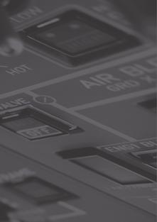
51 Systems 42/ FGCP (Flight Guidance and Control Panel) ATA 22 NAV SOURCE Selector CAPT side Select the NAV source for CAPT EHSI and/or ND (FMS1, VOR/ILS1, VOR/ ILS2, FMS2) VS mode to use FD with a desired vertical speed AP pb engages autopilot and yaw damper and disengages only autopilot IAS mode to use FD with a target indicated airspeed. (Cyan speed bug: MAN on ICP) (Magenta speed bug: AUTO on ICP) NAV mode to use FD with VOR and LNAV course HDG mode to use FD with HDG SEL NAV SOURCE Selector F/O side Select the NAV source for F/O EHSI and/or ND (FMS1, VOR/ ILS1, VOR/ILS2, FMS2) CRS 1 knob selects course on CAPT EHSI and/or ND CRS 2 knob selects course on F/O EHSI and/or ND FD bars P/B to set ON/OFF HDG knob selects HDG bug on both EHSI and/or ND. Pushing on the knob, synchronize the heading to the actual one. APP mode to use FD with ILS information course (lateral and vertical): lateral (LOC) vertical (GS) Pitch wheel to adjust VS or pitch attitude in basic mode ALT mode to use FD with a desired altitude ALT knob controls the preselected altitude on PFD YD pb engages yaw damper and disengages yaw damper and autopilot if engaged CPL pb permit to couple AP/FD on CAPT or F/O side. Dual coupling for CAT 2 FD bars P/B to set ON/OFF BC mode to use FD with localizer in back course STBY pb cancels all FD upper modes (armed and captured and active modes) and returns in basic modes. 4. ICP (Index Control Panel) ATA 22,31 Speed target selection Selection of the speed bug between: AUTO: Speed bug managed by the FMS (Magenta) MAN: Speed bug set manually by the speed knob (Cyan) Speed knob Used to set the speed bug In MAN mode 56
52 F. Communications FCOM


53 Systems 42/ Schematic ATA 23 The communication system provides communication between: aircraft and ground stations cockpit crew stations cabin attendant station ground crew stations CAPT SIDE oxy mask mike hand mike boom set head set PTT switch nose wheel steering control PTT loudspeaker loudspeaker audio level audio control panel COM SYSTEM NAVIGATION SYSTEM COCKPIT VOICE RECORDER OBSERVER SIDE oxy mask boom set head set PTT switch REMOTE CONTROL AUDIO UNIT CABIN ATTENDANT GROUND CREW PASSENGER F/O SIDE oxy mask mike hand mike boom set head set PTT switch loudspeaker loudspeaker audio level audio control panel PUBLIC ADDRESS SYSTEM GPWS TCAS 2. PTT selector and NOSE WHEEL STEERING CONTROL SW ATA23 PTT selector interphone: forward position neutral: center position radio: backward position NOSE WHEEL STEERING CONTROL switch When depressed, BOOM SET or OXY mike is connected for transmission 58


54 F. Communications 3. Audio control panel ATA 23 Transmission keys Only one key can be engaged at a time. It illuminates white when selected Volume control knob to set volume from associated communication or navigation facilities VOICE ONLY key When depressed, it inhibits NAV receivers station identification. Light illuminates amber when selected. INT/RAD selector Provides selection of transmission mode when using OXY MASK or BOOM SET mike INT: hot mike position. Interphone is always operative between crew stations. Other transmissions require to select a transmission key and use a PTT pb NEUTRAL: Interphone is inoperative. Other transmissions require selecting a transmission key and using a PTT pushbutton. RAD: This position is required to automatically connect for transmissions BOOM SET and OXY MASK mikes without using a PTT pb, when released the selector is springloaded to NEUTRAL. 4. VHF control ATA 23 VCP MCDU MCP MCP and MCDU allow to tune VHF frequencies MCDU allows to: set the squelch (SQL - ON/OFF) set directly the EMER frequency (121.5 Mhz) VHF 1 Frequency Display Selection Push Button To change the selection cursor To VHF Rotary selector To tune the VHF frequency 59


55 Systems 42/ AUDIO SEL pb ATA 23 FAULT illuminates amber and the FWS is activated when an associated RCAU processing board failure or power loss is detected AUDIO SEL Controls functioning of associated RCAU processing board. NORM: RCAU functions normally ALTN affected crew station is connected directly to VHF 1 for CAPT station or VHF 2 for F/O station. Volume is adjusted by affected loudspeaker volume control 6. Loudspeaker volume knobs ATA 23 LOUDSPEAKER Communication reception. In case of aural alert: normal volume is always available regardless of knobs position. during any transmission the volume of both loudspeakers is muted 7. TCAS control box ATA 34 VCP MCDU MCP MCP and MCDU allow to set between AUTO, TA ONLY and STBY MCDU allows to set between ABV, NORM, BLW on the displays. 60


56 F. Communications 8. EMER LOC XMTR panel ATA 23 AUTO TEST RST is used in case of undue alert or to test the emergency beacon. two cases are possible for the test network X MIT ALERT illuminates amber during 2 failure XMIT ALERT lt flashes during 15 seconds Switch AUTO transmission is made automatically on MHz, 243 MHz and 406 MHz when deceleration exceeds 5 g MAN allows commanded operation or test 9. Cabin attendant handset ATA 23 Cabin attendant handset PA: public adress to make an annoncement to passengers INT: internal communications with crew EMER: emergency call 10. Handmike and handset ATA CALLS panel ATA 23 EMER illuminates in case of emergency call from cabin CALLS ATTND to call cabin from cockpit. One time for a normal call three times for an emergency call MECH to call the ground crew from cockpit A horn is generated In case of cabin crew or ground crew call, depress RESET to cancel both associated visual and aural alerts 12. Head set / boom set / hand mike panels ATA 23 Head set / boom set panel / hand mike panels allows connection of a boom set, a head set and a hand mike 61
 to set the ALT mode (ON/OFF) to set XPDR 1 or 2 MCP MCDU MCDU allows to: set the flight")


57 Systems 42/ ATC control ATA 23 VCP MCP and MCDU allow: to set the transponder code to set the mode (ON/ STBY) to set the ALT mode (ON/OFF) to set XPDR 1 or 2 MCP MCDU MCDU allows to: set the flight identification (FLT ID) set directly the EMER code (7700) 14. CVR panel ATA 23 COCKPIT VOICE RECORDER Monitor indicator for test only. Movement of pointer in white band indicates all channels are operative HEADSET jack when headset is plugged into the jack: cockpit sounds picked up by the microphone are audible erase tone is audible when ERASE pb is depressed TEST pb when depressed and held, the test circuit is activated the pointer moves to a location between graduations 8 and 10 if a headset is plugged into the jack, the 600 HZ signal is heard ERASE pb provides fast erasure of recordings when the landing gear shock absorbers are compressed and parking brake is set (depress for 2 sec. to completly erase) During erasure, a 400Hz audio signal can be heard in the headset MICROPHONE picks up cockpit conversations and alert sounds 15. Crew oxygen mask ATA 23 A micro phone is incorporated inside the crew oxygen mask 62
58 G. Electrical systems FCOM
 Alternating current with constant frequency (AC) Alternating current with variable frequency (ACW) Two DC")
59 Systems 42/ Sources of power ATA 24 Three type of currents are available: Direct current (DC) Alternating current with constant frequency (AC) Alternating current with variable frequency (ACW) Two DC starter/generators <45% NH starter mode >61,5% NH generator mode Two batteries DC power 28 VDC Two inverters AC power VAC 26 V VAC 115 V DC GPU Two AC wild frequency alternators minimum NP 66% ACW power 115V/200V TRU (Emergency supply) DC power 28 VDC AC GPU The TRU provides power to the emergency loads in case of dual DC generators loss. It is supplied by the ACW bus 2. 64
60 G. Electrical systems The DC Starter Generator is driven by the HP spool throught the Accessorry Gear Box (AGB) From 0 to 45% NH as a Starter Above 61.5% as a Generator The ACW Generator is driven by the Reduction Gear Box, and is available when NP > 66% DC Starter Generator Accessory gear box ACW Generator Reduction gear box In Hotel Mode or with the propeller feathered, there is no ACW. When the propeller is unfeathered (CL in AUTO /100% OVRD), The NP is maintained at a minimum of 70,8%, in order to have ACW (minimum 66%) DC Starter Generator Accessory gear box ACW Generator Reduction gear box HOTEL MODE OR PROPELLER FEATHERED 65

61 Systems 42/ DC-AC schematic ATA Normal supply: On ground with battery only AC BUS 1 AC BUS 2 AC STBY BUS INV 1 BAT ON INV 2 TRU DC STBY BUS DC EMER BUS DC ESS BUS HOT EMER BAT BUS EMER BAT CHG HOT MAIN BAT BUS MAIN BAT CHG DC/AC overhead panel DC BUS 1 DC GEN 1 DC SVCE BUS GND HDLG BUS UTLY BUS 1 UTLY BUS 2 EXT. PWR BTC DC BUS 2 DC GEN 2 The GOUND HANDLING BUS is supplied only on ground, by three different ways: BAT OFF or BAT ON with the EXT PWR not available, the GND HDLG BUS is supplied by the HOT MAIN BAT BUS for ground servicing only when: - The refueling panel is open - The cargo door control panel is open - The passenger door is open BAT OFF or BAT ON with the EXT PWR available but not ON, the GND HDLG BUS is supplied from the EXT PWR via the DC SVCE BUS BAT ON with EXT PWR ON or with one GEN on line, the GND HDLG BUS is supplied by the from the DC BUS 1 via DC SVCE BUS. NOTE: The GND HDLG BUS is disconnected when airborne. ELEC SD page: on battery only ELEC SD page: on battery + GPU available 66

62 G. Electrical systems 2.2. Normal Supply: On ground with external power AC BUS 1 AC BUS 2 AC STBY BUS INV 1 BAT ON INV 2 TRU DC STBY BUS DC EMER BUS DC ESS BUS HOT EMER BAT BUS EMER BAT CHG HOT MAIN BAT BUS MAIN BAT CHG DC BUS 1 UTLY BUS 1 UTLY BUS 2 DC BUS 2 DC/AC overhead panel DC SVCE BUS BTC DC GEN 1 EXT. PWR DC GEN 2 GND HDLG BUS The BTC is closed and the GPU supplies all the DC and AC busses. Even if the GEN are available, the GPU has always priority. ELEC SD page 67

63 Systems 42/ Hotel mode or DC GEN 1 FAULT AC BUS 1 AC BUS 2 AC STBY BUS INV 1 BAT ON INV 2 TRU DC STBY BUS DC EMER BUS DC ESS BUS HOT EMER BAT BUS EMER BAT CHG HOT MAIN BAT BUS MAIN BAT CHG DC BUS 1 UTLY BUS 1 UTLY BUS 2 DC BUS 2 DC/AC overhead panel BTC DC SVCE BUS DC GEN 1 EXT. PWR DC GEN 2 GND HDLG BUS The BTC is closed and the GEN 2 supplies all the DC and AC busses. In hotel mode the GND HDLG BUS is supplied by the DC BUS 1 through the DC SVCE BUS. ELEC SD page 68

64 G. Electrical systems 2.4. Normal supply: with two generators on line AC BUS 1 AC BUS 2 AC STBY BUS INV 1 BAT ON INV 2 TRU DC STBY BUS DC EMER BUS DC ESS BUS HOT EMER BAT BUS EMER BAT CHG HOT MAIN BAT BUS MAIN BAT CHG DC BUS 1 UTLY BUS 1 UTLY BUS 2 DC BUS 2 DC/AC overhead panel DC SVCE BUS BTC DC GEN 1 EXT. PWR DC GEN 2 GND HDLG BUS The BTC is opened and each GEN supply its respective busses. On ground the GND HDLG BUS is supplied by the DC BUS 1 through the DC SVCE BUS, and disconnected when airborne. ELEC SD page 69

65 Systems 42/ Emergency supply: In dual DC GEN LOSS with the battery toggle switch on OVRD AC BUS 1 AC BUS 2 INV 1 AC STBY BUS BAT OVRD INV 2 The BAT toggle switch has to be selected to OVRD. The OVRD position ensures that busses are supplied by their respective battery by overriding all protections. This position is protected by a switch guard. TRU DC STBY BUS DC EMER BUS DC ESS BUS HOT EMER BAT BUS EMER BAT CHG HOT MAIN BAT BUS MAIN BAT CHG DC BUS 1 UTLY BUS 1 UTLY BUS 2 DC BUS 2 BTC DC SVCE BUS DC GEN 1 EXT. PWR DC GEN 2 GND HDLG BUS DC/AC overhead panel ELEC SD page 70

66 G. Electrical systems 2.6. Emergency supply: In dual DC GEN LOSS with the battery toggle switch on OVRD and second OVRD selected AC BUS 1 AC BUS 2 INV 1 AC STBY BUS BAT OVRD INV 2 After a Dual DC GEN loss, the UNDV is triggered when the DC STBY BUS <19,5 V. Then, by pushing on the OVRD the DC and AC STBY BUS are transfered from the HOT MAIN BAT BUS to the HOT EMER BAT BUS. When passing to OVRD, the DC STBY BUS voltage is recovered and the UND/V extinguishes. TRU DC STBY BUS DC EMER BUS DC ESS BUS EMER BAT CHG HOT EMER BAT BUS HOT MAIN BAT BUS MAIN BAT CHG DC BUS 1 UTLY BUS 1 UTLY BUS 2 DC BUS 2 DC SVCE BUS DC GEN 1 EXT. PWR DC GEN 2 BTC GND HDLG BUS DC/AC overhead panel ELEC SD page: Dual DC GEN Loss with first and second override (DC STBY BUS) 71

67 Systems 42/ Emergency supply: In dual DC GEN LOSS with TRU AC BUS 1 AC BUS 2 AC STBY BUS INV 1 BAT OVRD INV 2 TRU ON DC STBY BUS DC EMER BUS DC ESS BUS EMER BAT CHG HOT EMER BAT BUS HOT MAIN BAT BUS MAIN BAT CHG DC BUS 1 UTLY BUS 1 UTLY BUS 2 DC BUS 2 DC/AC overhead panel DC SVCE BUS DC GEN 1 EXT. PWR DC GEN 2 BTC GND HDLG BUS The TRU connected to the ACW BUS 2 supplies DC EMER BUS, DC ESS BUS, DC&AC STBY BUSSES. ELEC SD page 72
68 G. Electrical systems 3. DC-AC panel ATA 24 UNDV DC STBY < 19.5 V. ELEC STBY UNDV on FWS BUS OFF Associated bus deenergized. ELEC AC 1 (2) on FWS OVRD Xfer/stby busses from HOT MAIN to HOT EMER BAT BUS Arrows Emergency supply indicators (respective battery discharging) TRU ON PB in. TRU is connected to ACW BUS 2. Arrow illuminates green when DC EMER, DC STBY, INV 1, AC STBY and DC ESS BUS are supplied by TRU EMER BAT CHG FAULT: Overheat detected by MFC or failure of contactor. ELEC BAT CHG on FWS Contactor auto opens if: thermal runaway/bus voltage <25 V. Start sequence: Bat sw on OVRD INV FAULT Under/over voltage at INV output. (INV failure or supply loss). Auto- Xfer of all AC busses to remaining inverter. ELEC INV 1 (2) on FWS OVRD Insures basic mode operation by overriding all other protections ON Basic mode: STBY busses supplied by HOT MAIN BAT BUS. Ext or gen power: DC STBY bus transferred to HOT EMER BAT BUS AC STBY BUS to DC BUS 1 OFF ESS BUS, DC STBY BUS + INV 1 are isolated from HOT MAIN BAT BUS DC EMER BUS is isolated from HOT EMER BAT BUS DC BUS OFF Respective bus not supplied. ELEC DC 1 (2) on FWS DC SVCE/UTLY BUS DC SVCE supplies power in flight and on ground during airplane servicing operations. UTLY BUSSES supply nonessential loads SHED: In automatic shedding One of the DC SVCE/UTLY 1 and 2 busses is shed by the BPCU. SHED: In manual shedding (P/B selected OFF) all DC SVCE/UTLY 1 and 2 busses are shed BTC The BPCU controls BTC operation. Ext power, hotel mode or single gen operation, BTC is closed (green flow bar) ISOL BTC and BTR opened (released out) DC GEN 1/2 FAULT: protection trip by GCU; Auto reset if underspeed. BTC auto closes ELEC DC 1 ( 2) on FWS DC GEN 1/2 Generator FAULT Lt. Extinguishes above 61.5% NH if GEN is operating normally AVAIL GPU has been checked by BPCU for over/under voltage, over current and polarity X START FAIL Opposite generator has not come on line to assist start at 10 % NH ELEC X START on FWS EXT PWR AVAIL + ON: GPU has prioity on both generators 73

69 Systems 42/ Elec SD
70 G. Electrical systems Item Display Description Item Display Description 1 DC GEN X EXT PWR AVAIL ON DC GEN P/B ON & NORMAL OPERATION DC GEN P/B OFF DC GEN FAULT EXTERNAL POWER AVAILABLE 8 TRU TRU ACW TRU ACW TRU ACW TRU TRU P/B OFF WITH ACW BUS 2 OFF TRU P/B OFF WITH ACW BUS 2 ON AND TRU SUPPLY NOT AVAILABLE GREEN LINE WITH FULL ARROW COMING FROM ACW WHITE LABEL TRU P/B ON WITH ACW BUS 2 ON AND TRU SUPPLY NOT AVAILABLE GREEN LINE WITH FULL ARROW COMING FROM ACW WHITE LABEL TRU P/B ON WITH ACW BUS 2 ON AND TRU SUPPLY AVAILABLE GREEN LINE WITH FULL ARROW COMING FROM ACW WHITE LABEL TRU P/B ON WITH ACW BUS OFF 2 3 EXT PWR AVAIL ON EXT PWR ON ON BTC ISOL BTC ISOL EXTERNAL POWER AVAILABLE AND SELECTED (ON) EXTERNAL POWER NOT AVAILABLE BUT SELECTED NORM CONDITION ISOL CONDITION 9 10 TRU ACW EMER BUS EMER BUS OVRD UNDV DC STBY BUS OVRD UNDV DC STBY BUS TRU P/B OFF WITH ACW BUS 2 ON AND TRU SUPPLY AVAILABLE GREEN LINE WITH FULL ARROW COMING FROM ACW WHITE LABEL EMER BUS VALID VOLTAGE AND >18V EMER BUS INVALID VOLTAGE AND/ OR <18V DC STBY BUS VALID VOLTAGE AND >18V WITH OVRD UND/V PB IN NORM POS. DC STBY BUS VALID VOLTAGE AND >18V WITH OVRD UND/V PB IN OVRD POS. 4 UTLY BUS X DC BUS X ON DC BUS X OFF DC BUS ON DC BUS OFF DC UTLY BUS ON 11 OVRD UNDV DC STBY BUS ESS BUS ESS BUS DC STBY BUS INVALID VOLTAGE AND/OR <18V DC ESS BUS 1 (OR 2) VALID VOLTAGE AND >18V DC ESS BUS 1 (OR 2) INVALID VOLTAGE AND <18V 5 UTLY BUS X DC UTLY BUS OFF UTLY BUS X DC UTLY BUS FAULT 6 SHED DC UTILITY BUS SHED MESSAGE SVCE BUS DC SVCE BUS ON 7 OFF SVCE BUS DC SVCE BUS OFF OFF SVCE BUS DC SVCE BUS FAULT 75
71 Systems 42/
72 G. Electrical systems Item Display Description Item Display Description HOT BUS MAIN BAT 28 V DC MAIN BUS VALID VOLTAGE AND >18V HOT BUS EMER BAT 28 V DC EMER BUS VALID VOLTAGE AND >18V 12 HOT BUS MAIN BAT 28 V DC MAIN BUS VALID VOLTAGE AND >18V WITH BAT TOGGLE P/B SW IN OVRD POSITION 16 HOT BUS EMER BAT 28 V DC EMER BUS VALID VOLTAGE AND >18V WITH BAT TOGGLE P/B SW IN OVRD POSITION HOT BUS MAIN BAT 28 V XX V XX V DC MAIN BUS INVALID VOLTAGE OR <18V DC MAIN BAT VALID VOLTAGE AND >18V DC MAIN BAT VALID VOLTAGE AND <18V -- V DC MAIN BAT INVALID VOLTAGE CHG OFF CHG OFF CHG OFF CHG FAULT MAIN BAT CHG P/B SW RELEASED (CHARGE CONTACTOR OPENED) MAIN BAT CHG P/B SW PRESSED IN (CHARGE CONTACTOR CLOSED) WITH DC BUS 2 NOT SUPPLYING THE MAIN BATTERY OR WITH TOGGLE P/B SW ON OVRD POSITION, OR CAUTION ON MAIN DC BAT MAIN BAT CHG P/B SW PRESSED IN (CHARGE CONTACTOR CLOSED) WITH DC BUS 2 SUPPLYING THE MAIN BATTERY OR WITH TOGGLE P/B SW NOT ON OVRD POSITION MAIN BAT CHG P/B SW PRESSED IN (CHARGE CONTACTOR CLOSED) WITH DC MAIN DC BAT IN FAULT IF ABNORMAL DISCHARGE OF THE MAIN BATTERY HOT BUS EMER BAT 28 V EMER BAT XX V EMER BAT XX V EMER BAT -- CHG OFF CHG OFF CHG OFF CHG FAULT DC EMER BAT INVALID VOLTAGE OR <18V DC EMER BAT VALID VOLTAGE AND >18V DC EMER BAT VALID VOLTAGE AND <18V V DC EMER BUS INVALID VOLTAGE EMER BAT CHG P/B SW RELEASED (CHARGE CONTACTOR OPENED) EMER BAT CHG P/B SW PRESSED IN (CHARGE CONTACTOR CLOSED) WITH DC BUS 1 NOT SUPPLYING THE EMER BATTERY OR WITH TOGGLE P/B SW ON OVRD POSITION EMER BAT CHG P/B SW PRESSED IN (CHARGE CONTACTOR CLOSED) WITH DC BUS 1 SUPPLYING THE EMER BATTERY AND WITH TOGGLE P/B SW NOT ON OVRD POSITION, OR CAUTION ON EMER DC BAT EMER BAT CHG P/B SW PRESSED IN (CHARGE CONTACTOR CLOSED) WITH DC EMER BAT IN FAULT IF ABNORMAL DISCHARGE OF THE EMER BATTERY 20 BAT OVRD IF TOGGLE SW IN OVRD POSITION Item Display Description 21 AC BUS 1 OF AC BUS X OFF AC BUS ON AC BUS OFF INV X FAULT INV X FAULT AC STBY BUS AC STBY BUS AC STBY BUS ON AC STBY BUS OFF INVERTER NORMAL FUNCTIONNING INVERTER FAULT 77
 but not ON, the GPU supplies only")
73 Systems 42/ ACW schematic ATA 24 ACW BUS 1 ACW BUS 2 TRU SVCE BUS ACW GEN 1 ACW GPU ACW GEN 2 NP=0 NP=0 ACW supplied by the External Power When the AC GPU is available (AVAIL) but not ON, the GPU supplies only the ACW Service Bus, if the GND Service Bus switch, on the flight attendant panel, is ON. When the AC GPU is ON, the GPU supplies through the BTC, the ACW BUS 1, the ACW BUS 2 and the ACW SVCE BUS. Even if one ACW generator is available, the GPU has always priority. ACW BUS 1 ACW BUS 2 TRU SVCE BUS ACW GEN 1 ACW GPU ACW GEN 2 NP=0 NP=0 in hotel mode NP<20% with prop feathered ACW in Hotel mode or with the propeller feathered NOTE: An ACW Generator is available if the NP is above 66%. When the right engine is running in hotel mode, the NP=0. When the engines are running but the propellers are feathered, the NP is bellow 20% In both cases the ACW Busses are not supplied 78
74 G. Electrical systems ACW BUS 1 ACW BUS 2 TRU SVCE BUS ACW GEN 1 ACW GPU ACW GEN 2 NP=0 NP=70.8% The propeller unfeathered and one ACW GEN on line On ground, when the propeller is unfeathered, the engine is running on fuel governing mode. The fuel governing mode, maintain a minimum NP of 70.8%, in order to have the ACW available (ACW GEN on line at 66%) The ACW GEN supplies, the ACW BUS 2 and ACW BUS 1 through the BTC, but the SVCE BUS is shed (one generator is not able to supply all the busses) CAUTION: on ground in case of an EEC or PEC fault, the fuel governing mode is lost and the ACW generator is not available (NP<66%) ACW BUS 1 ACW BUS 2 TRU SVCE BUS ACW GEN 1 ACW GPU ACW GEN 2 NP=100% NP=100% Normal condition in flight The ACW GEN 1 supplies the ACW BUS 1 and the ACW SVCE BUS The ACW GEN 2 supplied the ACW BUS 2. The TRU is connected to the ACW BUS 2 79
75 Systems 42/ ACW BUS 1 ACW BUS 2 TRU SVCE BUS ACW GEN 1 ACW GPU ACW GEN 2 NP=100% NP=100% One Generator Fault When one generator is fault, the other one supplies the ACW BUS1 and the ACW BUS 2 through the BTC. The SVCE BUS is automatically shed (one generator is not able to supply all the busses) 6. ACW panel ATA 24 ACW BUS OFF Associated bus not supplied. ELEC ACW 1 (2) on FWS BTC (green flow bar) Auto closure when either ACW GEN drops off line ACW GEN 1 /2 FAULT: Auto reset in case of under/over speed. ACW SVCE BUS auto shed if 1 GEN is out. ELEC ACW GEN 1(2) on FWS EXT PWR AVAIL + ON GPU has priority over both GEN ACW GEN 2 and ACW GEN 1 Min NP for ACW = 66 %. The fuel governing mode maintains a MIN NP of 70.8% to be always above 66%. The fuel governing mode is cancelled with the propeller feathered (No ACW) 80

76 G. Electrical systems 7. SD page Item Display Description Item Display Description ACW GEN1 ACW GEN ON DC TRU P/B OFF WITH ACW BUS 2 TRU OFF 1 ACW GEN1 OFF ACW GEN OFF DC TRU TRU P/B OFF WITH ACW BUS 2 ON AND TRU SUPPLY NOT AVAILABLE 2 ACW GEN1 FAULT ACW BUS x OFF ACW BUS x OFF ACW GEN FAULT ACW BUS ON ACW BUS OFF 5 DC DC TRU TRU TRU TRU P/B ON WITH ACW BUS 2 ON AND TRU SUPPLY NOT AVAILABLE TRU P/B ON WITH ACW BUS 2 ON AND TRU SUPPLY AVAILABLE TRU P/B ON WITH ACW BUS 2 OFF 3 4 BTC ISOL BTC ISOL EXT AC AVAIL ON EXT AC AVAIL ON NORM CONDITION ISOL CONDITION EXTERNAL POWER AVAILABLE EXTERNAL POWER AVAILABLE AND SELECTED ON 6 DC TRU DC BUS 2 MAIN BAT TRU P/B OFF WITH ACW BUS 2 ON AND TRU SUPPLY AVAILABLE HYD AUX PUMP SUPPLYING, DC BUS 2 ON HYD AUX PUMP SUPPLYING, DC BUS 2 OFF AND DC MAIN BAT VOLTAGE >18V EXT AC AVAIL ON EXTERNAL POWER NOT AVAILABLE BUT SELECTED ON 81

77 Systems 42/ Breaker panels ATA Overhead panel 82

78 G. Electrical systems 8.2. Electric rack behind F/O 83
79 H. Emergency equipment FCOM


80 Systems 42/ The aircraft is equipped with fire fighting, oxygen, first aid equipment and emergency lightning. 1. Emergency equipment situation halon extinguisher crash axe life jackets emergency exit type III type I service door oxygen bottle oxygen mask life jacket flash light flash light goggles oxygen masks halon extinguisher fire resistant gloves hood goggles oxygen mask water extinguisher flash light smoke hood emergency exit type III first aid kit bag containing oxygen masks smoke hood type I entry door 2. Emergency lighting system ATA 33 Emergency exit signs External emergency lighting Cabin general illumination External emergency lighting Emergency exit signs Emergency exit sign Emergency exit sign Floor proximity escape path marking Emergency exit signs External emergency lighting Emergency exit signs 86


81 H. Emergency equipment 3. First aid kit ATA 25 contains bandages, burn dressings, small adhesive dressings, antiseptic wound cleaner, adhesive wound closures, disposable resuscitation aid, wound dressings, large and small, adhesive tape, safety pins and scissors, simple analgesic, antiemetic, nasal decongestant, first-aid handbook, splints, suitable for upperand lower limbs, gastrointestinal antacid, anti-diarrhoel medication, disposable gloves 4. Crash axe ATA 25 Crash axe with pick and edge Handle insulated up to 2000V to open a door or a compartment 5. Megaphone ATA 25 megaphone (72 only) 6. Flashing light ATA 25 With batteries, morse code switch 7. Life jacket ATA 25 With oral inflation tube, CO2 sparklets, inflation red toggle, whistle, straps, battery, light 8. Escape rope ATA 25 used to evacuate the cockpit 87


82 Systems 42/ Gloves ATA 25 To protect against heat 10. Water extinguisher ATA 26 Water extinguisher 2 liters of water with an anti-ice additive discharge time: 30 to Halon extinguisher ATA 26 Halon extinguisher 1.2 kg of halon gas discharge time: 8 to Oxygen schematic ATA 35 To flight crew members Modules for 72/ Oxygen bottle 88


83 H. Emergency equipment 13. Oxygen panel and display ATA 35 MAIN SUPPLY pb in: crew supply only HP INDICATOR oxygen bottle pressure. Red arc 0 to 85 psi Green arc 85 to 2025 psi If below 1400 psi, use table PAX SUPPLY ON 25% off the passengers LO PR supply below 50 psi. OXY on FWS MAIN SUPPLY OFF MAIN SUPPLY ON PAX SUPPLY OFF PRESSURE AVAILABLE MAIN SUPPLY ON PAX SUPPLY ON PRESSURE AVAILABLE MAIN SUPPLY ON PAX SUPPLY OFF LOW PRESSURE DETECTED MAIN SUPPLY ON PAX SUPPLY ON LOW PRESSURE DETECTED 14. Cockpit crew oxygen mask ATA 35 PRESS TO TEST AND RESET permits a test of oxygen flow without removing the mask from the container. It is springloaded to the reset position BLINKER displays a yellow cross when there is oxygen flow and black when there is none. N/100% PUSH rocker controls the selection of normal or 100% oxygen for mask delivery. It is locked in the 100% position by the unlock rocker OXYGEN MASKS quick donning inflatable harness type release clips: squeeze them to unlock the container doors EMERGENCY selector activates pressurization of mask delivery flow when N/100% rocker is at 100% 89

 duration: 30 min at 4")


 to supply 15 min pure oxygen")
84 Systems 42/ Portable oxygen bottle ATA 35 Portable oxygen bottle (green) with pressure gauge and re-charge valve 120 liters under pressure (1800 psi) duration: 30 min at 4 ltr/mn 1 bottle > 42 2 bottles > Passenger oxygen mask ATA Oxygen masks for Oxygen masks for 72 equipped with valves, bag and elastic strap 17. Protective breathing equipment ATA 26 Protective breathing equipment (PBE) to supply 15 min pure oxygen with hood, visor, speaking diaphragm and oronasal mask 2 PBE > 42 3 PBE > 72 PBE stowage box 90
85 I. Fire protection FCOM


86 Systems 42/ The fire protection system provides detection, warning and extinguishing for each engine, cabin and lavatory. 1. Schematic ATA 26 FIRE DETECTION FIRE EXTINGUISHING SYSTEM AND Bottle N 1 Bottle N 2 ENG 1 ENG 2 2. Avionics FWD and AFT smoke detection ATA 26 FORWARD CARGO SMOKE DETECTION AFT CARGO OR LAVATORY SMOKE DETECTION AVIONICS COMPARTMENT SMOKE DETECTION AIR CAUTION / FAN FAILURE 92

 on FWS (DC emer) FAULT TEST MC + SC + LOOP on FWS Fault lights in A/B loop pb ENGINE FIRE HANDLE Pulled on the respective engine: PROP: feather FUEL: LP valve closed AIR: BLEED")

 Engine Fire detected by two loops. (Not detected if one loop fault. Detection recovered when the faulty loop is selected OFF) LOOP Engine fire loop FAULT.")
87 I. Fire protection 3. Fire handle ATA 26 SQUIB TEST Electrical test of the squibs AGENT 1 DISCH: Bottle depressurized. Opposite agent DISCH light will also illuminate on other fire panel. Bottle located in the wing fairing of the associated side AGENT SQUIB armed when T handle pulled. Discharges bottle. (DC EMER/HOT MAIN BAT) LOOP FAULT: change in resistance, inhibits fire signal until turned off. LOOP 1A (1B, 2A, 2B) on FWS (DC emer) FAULT TEST MC + SC + LOOP on FWS Fault lights in A/B loop pb ENGINE FIRE HANDLE Pulled on the respective engine: PROP: feather FUEL: LP valve closed AIR: BLEED and HP valve closed DEICING: deice and shutoff valve closed ELEC : DC and ACW gen. disconnected SQUIBS armed lts illumination + Hydraulic to prop brake closed on engine 2 Agent 2 bottle located on the opposite side FIRE TEST MW + CRC + ENG 1 FIRE on FWS + fire handle illuminated + FUEL S/O light on CL (if out of FUEL S/O position) OFF takes respective loop out of parallel circuit. Allows other loop to activate fire signal alone. 4. EWD (Engine and Warning Display) Engine Fire detected by two loops. (Not detected if one loop fault. Detection recovered when the faulty loop is selected OFF) LOOP Engine fire loop FAULT. When a loop FAULT. No detection of Engine Fire (Detection recovered when the faulty loop is selected OFF) Alert on FWS NAC OVHT RH Nacelle Overheat >170 C 5. Condition levers fuel light ATA 26 FUEL SO Illuminates red in case of fire signal from associated engine. Extinguishes after CL is set at fuel shut off position or if fire detection signal stops 93


88 Systems 42/ Compartment smoke panel ATA 26 SMK TEST Tests the smoke detectors operation NORM one fan runs FAULT: the fan is out of order and illuminates amber + FWS is activated ALTN: The alternate fan runs, ALTN light illuminates cyan Normal operation DET FANS ALTN DET FANS Fan Fault associated with AIR AFT DET FAN on FWS Aft Fan Fault, selection of the alternate FAN On SD CABIN 7. SD cabin Avionics smoke Forward cargo smoke Lavatory smoke Aft cargo compartment smoke Aft compartment & lavatory Detection fans 94
89 J. Flight control FCOM
90 Systems 42/ The elevators, ailerons and rudder are mechanically actuated The spoilers and flaps are hydraulically actuated. 1. Roll schematic ATA Pitch schematic ATA 27 In case of jamming, pitch control will be recovered by disengaging the pitch coupling system (by applying a differential force of 52 dan). 96


 5.")

91 J. Flight control 3. Yaw schematic ATA Gust lock ATA 27 GUST LOCK lever permits to lock mechanically the roll and pitch axes against wind gusts. The PL travel is limited to slightly above FI. Aircraft equipped with a spring tab on the aileron. The roll locking system is composed of two electro-mechanical locking devices. The AIL LOCK is triggered whenever one of the locking actuators is in disagreement with the gust lock position (lock or unlock position) 5. Stick Shaker/Stick Pusher push button and display ATA 27 STICK SHAKER/PUSHER PB FAULT light indicates a stick pusher or stick shaker failure OFF position: enables to switch OFF the stick pusher and the stick shaker system STICK PUSHER illuminates to indicate that the stick pusher is operating 97


92 Systems 42/ Spoilers position indicator ATA 27 SPOILERS position indicator When illuminated, each green light indicates that the associated spoiler is not in the fully retracted position (more than 2.5 aileron travel) 7. Pitch trim asym light ATA 27 PITCH TRIM ASYM Amber labels are displayed to indicate a pitch tabs desynchronization greater than Trim position indicator ATA 27 Pitch trim position indicates the right trim actuator controlled tab travel. A green sector identifies the take off range. If take off (or take off config test) is performed with pitch trim out of this range, CONFIG warning will be generated by the FWS. Roll trim position indicates the LH aileron trim controlled tab travel Yaw trim position indicates units of trim motor displacement 98
 AP engaged Manual mode Associated to: RETRIM ROLL L(R) WING DN In case of roll retrim with AP engaged The cyan arrow indicates the side to retrim The trim is inhibited on")
 Manual mode Yaw Damper off (no Yaw")
93 J. Flight control AP engaged Manual mode Associated to: PITCH TRIM ASYM on FWS Or PITCH MISTRIM or AP PITCH TRIM FAIL with AP engaged, on FMA and FWS Or Pointer outside of green band in pre take off condition (Take off CONFIG) AP engaged Manual mode Associated to: RETRIM ROLL L(R) WING DN In case of roll retrim with AP engaged The cyan arrow indicates the side to retrim The trim is inhibited on the other side. Associated to: AILERON MISTRIM On FMA The cyan arrow indicates the side to retrim The trim is inhibited on the other side Yaw Damper engaged (Yaw Auto Trim active) Manual mode Yaw Damper off (no Yaw Auto Trim) Associated to: RUDDER MISTRIM on FMA Or YAW AUTOTRIM FAIL on FWS The cyan arrow indicates the side to retrim 9. Trim controls ATA 27 Yaw TRIM control switches controls the yaw trim actuator. As a safety device both levers must be moved and held in the same direction (nose LH or nose RH) to energize the system and trim the aircraft. When used, the RCU is declutched. The Yaw TRIM manual control is inhibited when the autopilot is engaged (Yaw autotrim) When the autopilot is engaged, the RUDDER MISTRIM message can be triggered on FMA. Roll TRIM control SW controls the roll trim actuator. For operation, both sws must be moved and held in the same direction (L WING DN or R WING DN) to energize the system (safety reasons). The roll trim is inhibited during autopilot operation. When the autopilot is engaged, the RETRIM ROLL R(L) WING DOWN or AILERON MISTRIM messages can be triggered on the FMA. These messages authorize to retrim on the dedicated side. The other side is still inhibited STBY PITCH control SW is a guarded sw which controls the electrical motors of each trim actuator. Action on this switch will disengage the autopilot. Pitch trim rocker two switches installed on each control wheel. It is necessary to operate both rocker switches to activate the normal electrical motor of each trim actuator and to control nose up or down. The switches are spring loaded to neutral position. An aural whooler is generated by the FWS if trim is used for more than 1 second. Action on this switch will disengage the autopilot. 99

94 Systems 42/ Flaps schematic ATA Flaps position indicator ATA


")
95 J. Flight control 12. Flaps control lever ATA 27 FLAPS control lever controls the flaps operation. Distinct positions correspond to flaps 0, 15, 30 (72-600) or 25, 35 (42-600) 101
96 K. Flight instruments FCOM
. The SWM (Gateway and Switch module) is connecting together CPM (Core Processing Module) and other Avionics Data Network subscribers.")
97 Systems 42/ Schematic ATA 31 The Avionics Full DupleX switched ethernet (AFDX) allows transmission of data in all directions between the CAC 1&2 and the DUs. The AFDX is controlled by the SWM s (Module of the CAC). The SWM (Gateway and Switch module) is connecting together CPM (Core Processing Module) and other Avionics Data Network subscribers. SWM external interface mainly consists of: AFDX with the 5 Display Units, AFDX with the CPM, AFDX interconnection between the 2 SWM, Ethernet with dataloading Port. AFCS (Auto Flight Control System) is managed by the two Auto Flight Control Application (AFCA) of the CACs. The AFCAs receives data from the two ADC, two AHRS and aircraft equipments as navigation and some sensors.the AFCAs receives data from the two FMS (Flight Management Application: DU 2 & 4). The AFCS generates commands to flight control actuators and to the FD bars. AHRS (Attitude and Heading Reference System) comprises: (1) An AHRU (Attitude and Heading Reference Unit) which integrates inertial components, to compute the gyro-heading, the attitude, acceleration and the vertical speed. (2) A Removable Memory Module to store compensation parameters (3) A flux valve which detects the direction of the earth s magnetic field line. The AHRS gyro-magnetic heading computation automatically updates the heading value with the magnetic heading of the flux valve. ADC (Air Data Computers) is supplied with static air pressure (static ports), total air pressure (pitot ports), total air temperature (TAT probe). With these inputs, the ADC computes pressure altitude, IAS, TAS, TAT, SAT. DU (Display Unit): Collects all the data, coming from the AFDX (CAC 1 & 2), from Arinc 429 (control panels, CACs, aircraft equipments), from discrete lines Converts the data in video format, through the FDA (Flight Display Application). NOTES: The FMA (Flight Management Application) and RMA (Radio Management Apllication) are part of the DU 2 & 4 Each DU can display three different formats: the Primary Flight Display (PFD), the Multi Function Display (MFD), the Engine and Warning Display (EWD) 104
 ATA 31 Lateral ARM, CAPTURE and HOLD mode ROLL ATTITUDE scale 0, 10, 20, 30, 45 and 60 Flight Mode Annunciator (FMA) Bank angle limit: two green ticks Vertical ARM,")
98 K. Flight instruments 2. PFD (Primary Fight Display) ATA 31 Lateral ARM, CAPTURE and HOLD mode ROLL ATTITUDE scale 0, 10, 20, 30, 45 and 60 Flight Mode Annunciator (FMA) Bank angle limit: two green ticks Vertical ARM, CAPTURE and HOLD mode SLIP indicator Horizon and pitch scale is white and has reference marks every 2.5 up to 20 up or down, then marks at 25, 30, 50, 80. FLIGHT DIRECTOR command bars (green) Vertical deviation indication RADIO ALTITUDE indication VSI (Vertical Speed Indicator) Altimeter: altitude tape Lateral deviation indication TCAS and Transponder annunciator DH indication Indication of True Air Speed, Ground Speed, and wind Airspeed indicator: Speed tape EHSI (Electronic Horizontal Situation Indicator). The EHSI can be replaced by a mini ND (Navigation Display) when the the ND is replaced by an other format on the MFD. 105
 ATA 31 MFD")
 MFD")
99 Systems 42/ MFD (Multi Function Display) ATA 31 MFD upper window Memo panel display VCP (Virtual Control Panel Window) MFD upper window selection 106
 ATA 31 Trim indicator Primary engine display Brake messages")
100 K. Flight instruments 4. EWD (Engine and Warning Display) ATA 31 Trim indicator Primary engine display Brake messages Test status Permanent Data Flap indicator Alert window Procedure window


101 Systems 42/ ND - ARC MODE with terrain or weather radar information ATA 31 TERRAIN WEATHER RADAR 6. Source failure alert ATA 31 DU total loss FAIL A fatal failure has been detected by DU software or by the hardware AHRS failure ADC failure 108

. In case of failure of any DU (DU 1 or 2 on capt side or DU 4 or 5 on F/O side) enables to cycle the three formats on the remaining DU 8.")

102 K. Flight instruments 7. Switching panel ATA 34 ATT/HDG pb enables to use AHRS 2 information. When captain pb is depressed SYS 2 illuminates white on CAPT pb, CAPT 2 illuminates green on F/O pb ADC pb enables to use ADC 2 information. When captain pb is depressed SYS 2 illuminates white on CAPT pb, CAPT 2 illuminates green on F/O pb DISPLAY pb In normal conditions, enables to cycle the three formats on DU 2 (capt switching), on DU 4 (F/O switching). In case of failure of any DU (DU 1 or 2 on capt side or DU 4 or 5 on F/O side) enables to cycle the three formats on the remaining DU 8. EFCP (control panel) ATA 31 MFD ND page: Three different ND format can be displayed on the MFD, by pressing on the ND push button, and then by selecting the format on the FORMAT rotary knob. MFD PERF page: The performance page can be displayed, by pressing on the PERF push button. MFD MISC page: Engine run up page MFD SYS page: Four different system pages can be displayed on the MFD, by pressing the SYS push button consecutively. MFD VID page: In provision for video display MFD MAP page: Airport map page (option) BRG1(2)push button: By pressing it, VOR1(2) or ADF1(2) or no indication is displayed. RANGE +/ push button: By pressing it, the range of the Navigation Display page is increased/decreased. FORMAT rotary knob: By turning it, the format of the ND is changed. RCL PB A first push enables to display in the Alert Window the alert messages previously cleared but still detected. A second push scrolls down the alert messages list in case of overflow in the alert window. MAN DEL By pressing on it, procedures inserted manually are deleted CLR PB By pressing on it, a clearable alert displayed on the Alert Window is cleared. PROC MENU By pressing on it, procedure menu is displayed in the procedure window. Procedure control pb: Allows to move on upward/downward line in the procedure window and to validate actions 109
 ATA 31 Multi directionnal pad To move the cursor")
 Enter P/B To validate the selection area NAV P/B Selection on VCP VOR")
 Before validation, the escape P/B allows to recover the previous value")
103 Systems 42/ MCP (Multipurpose Control Panel) ATA 31 Multi directionnal pad To move the cursor for choosing a selection area COM P/B Selection on VCP VHF HF 1 (if installed) HF 2 (if installed) Enter P/B To validate the selection area NAV P/B Selection on VCP VOR ADF ND OVLY (ND Overlay) SURV P/B (surveillance) Selection on VCP XPDR TCAS ESC P/B (Escape) Before validation, the escape P/B allows to recover the previous value Numeric Key Board Allows setting the frequency or transponder code. 110

 RCT pb activates Rain Echo Attenuation Compensation technique function and permits display with more accurracy the weather")
104 K. Flight instruments 10. Weather radar control ATA 34 Primus 660 GAIN setting to set receiving amplification MODE selector OFF radar is off STBY radar is on but no pulse is sent by the antenna TEST range at 100 NM, 3 arcs green, yellow and red WX normal operating position, intensity of weather obstacles is displayed by different colors (black: no cloud; green: normal cloud; yellow: dense; red: severe storm) G MAP enables to display ground obstacles (black, pale blue, yellow, magenta) RCT pb activates Rain Echo Attenuation Compensation technique function and permits display with more accurracy the weather situation behind storms TGT pb activates target alert SECT pb Used to select either the normal 12 looks/minute 120 sector scan or the faster update 24 looks/ minute 60 sector scan TILT control to adjust radar antenna in pitch axis from 15 down to 15 up Turns the pitch and roll stability on and off. When selected off, an amber legend illuminates above the pushbutton 111

 indicate which mode is selected (the")
.")


105 Systems 42/ TAT/SAT indicator ATA 34 TAT indicator indicates total air temperature SAT indicator indicates static air temperature TAS indicator indicates true air speed 12. CLOCK ATA 31 MODE P/B By pressing the MODE pushbutton, six annunciators (DT, GPS, INT, LT, ET and CHR) indicate which mode is selected (the functions INT, LOC and DT are available in succession, ET and CHR functions are controlled by the ET and CHR buttons respectively, the GPS is automatically selected when GPS is valid). Chronometer (CHR) P/B START: Display is active and the chronometer starts incrementing STOP: The value displayed at the instant the push-button was depressed is held as long as no action occurs on this push button. RESET: the LCD display is zeroed and blanked. Elapsed time (ET) P/B When selecting the ET push button, the ET display comes on. When the elapsed time counter is stopped, by pressing the ET push button for more than two seconds the display is blanked and value is zeroed. For the time set, the ET P/B is used to decrease the digits (-) TEST P/B For the time set, the TEST P/B is used to increase the digits (+) Six digits display of either: Universal Time Coordinated (from GPS or internal time) Date: MONTH / DAY / YEAR Local Time Four digits display of either: ELAPSED TIME (ET) CHRONOMETER TIME (CHR) ELAPSED TIME When depressed ON the flight time starts automatically when airborne 112


106 K. Flight instruments 13. RCDR panel ATA 31 RCDR pb when depressed, both cockpit voice recorder and digital flight data recorder are energized (manual mode). ON lt illuminates cyan RESET pb when depressed, inhibits recording in the manual mode 14. STBY instruments ATA 34 STANBY COMPASS STANDBY COMPASS Hidden in up position. Compass control should be placed on DN for use. The compass rose is graduated in 10 degrees increments IESI: Integrated Electronic Standby Instrument LATERAL ACCELERATION INDEX indicates the aircraft s lateral acceleration. It is represented by a trapezoidal index that moves beneath the roll index. Brightness Menu P/B Enable sub function selection menu STD P/B Reset at Hpa, when pushed more than 0.2 sec. STANDBY AIRSPEED INDICATOR The actual airspeed is given in a T shaped window positioned in the center of the white moving speed tape on the left of the IESI. STANDBY HORIZON The pitch scale has markers every 2.5 degrees up to ±20. If pitch exceeds ±25 degrees large red chevron will indicate excessive attitude and direction to follow to resume normal attitude. The roll scale has markers are set at 10, 20, 30, 45, 60 degrees of bank. SEL P/B Change cursor selection between VHF COM, VHF NAV, BARO SETTING and COURSE when VOR mode. SET ROTARY SWITCH Sub fonction menu scroller Baro setting VHF com tuning VHF nav tuning Course setting in VOR mode STANDBY ALTIMETER The altitude indication is given in a rectangular window positioned in the center of the white moving altitude tape on the right of the IESI. Altitude in meters can also be displayed on the IESI underneath the altitude tape. The barometric reference is displayed in cyan. It corresponds to either the selected barometric pressure or the standard pressure. 113
 managed by the FMS.")
 Actual IAS VmLB0 (icing condition) VmLB0 (normal condition) Flaps retraction speed VminOPS Upper amber limit VPROT Upper red limit")
 VmHB15 icing (amber line) Flaps retraction speed Vref VmHB30 or Vmcl whichever is higher Approach Flaps 15 Approach Flaps 30 The")
107 Systems 42/ Airspeed indicator ATA 34 Speed bug read out Speed trend Predicted airspeed in 10s Speed bug Automatic speed bug (Magenta) managed by the FMS. Manual speed bug (Cyan) selected on the ICP. V1, VR and V2 (Cyan) Actual IAS VmLB0 (icing condition) VmLB0 (normal condition) Flaps retraction speed VminOPS Upper amber limit VPROT Upper red limit Activation of the stick shaker Maximum speed Vmo/Mmo or Vfe or Vle or Vtlu Before rotation Initial climb Cruise Flaps extension speed (VFE NEXT) VmHB15 normal (white line) VmHB15 icing (amber line) Flaps retraction speed Vref VmHB30 or Vmcl whichever is higher Approach Flaps 15 Approach Flaps 30 The speed bug is controlled by the ICP (Index Control Panel) Speed target selection Selection of the speed bug between: AUTO: Speed bug managed by the FMS Speed knob Used to set the speed bug In MAN mode MAN: Speed bug set manually by the speed knob 114
 then a yellow frame is")

108 K. Flight instruments 16. Altimeter ATA 34 Selected Altitude ALT SEL Current altitude or FL ALTITUDE ALERT An amber frame is flashing (± 1000ft) then a yellow frame is steady (± 250ft) DA / MDA Landing Elevation Barometric setting in Hpa and InHG Barometric setting knob The knob is used to set the barometric reference. Pushing the knob sets standard barometric reference (29.92 INHG / Hpa) DH / MDA knob Outer knob permits to select between DH (Decision Height) or MDA (Minimum Descent Altitude). Inner knob is used to set DH or MDA values, depending of the outer knob position. 115
 VS")
 Above (+) or Below ( ) separation height descending or")
 vertical rates to be avoided.")
 Traffic in warning area 15 to 35s before collision area RANGE RING 2.")
109 Systems 42/ Vertical speed indicator and TCAS ATA 34 VS digital readout VS target readout Set by the FGCP Pitch Wheel (PW) VS scale VERTICAL SPEED INDICATOR based on both inertial (AHRS) and barometric data (ADC). VS pointer VS target Set by the FGCP Pitch Wheel (PW) Above (+) or Below ( ) separation height descending or climbing Open diamond Other traffic Solid diamond Proximate traffic (PA) traffic within ± 1200 ft and 6 NM TCAS Status Resolution Advisory (RA) vertical rates to be avoided. Solid circle Traffic Advisory (TA) Traffic in caution area 20 to 48s before collision area Solid cube Resolution Advisory (RA) Traffic in warning area 15 to 35s before collision area RANGE RING 2.5NM around the A/C AIRCRAFT own aircraft symbol TCAS no bearing advisory: In case the bearing of the TA or RA intruder is not available, a message provides an indication on the two most dangerous RA or TA intruders 116
110 L. Fuel system FCOM


 Main wing tank Feeder tank (200 l / 160 kg)")
")
111 Systems 42/ Schematic ATA 28 The fuel is stored in two tanks, one in each wing. Each tank is fitted with: a vent surge tank to ensure positive pressure and allows a thermal expansion without spillage a main wing tank a feeder tank, always full to protect the engine feed system against negative or lateral load factors ATR 42 Total quantity 4500 kg Gravity filling cap Refueling panel Refueling point Access door Main wing tank Vent surge tank (100 l) Main wing tank Feeder tank (200 l / 160 kg) Vent surge tank ATR 72 Total quantity 5000 kg Gravity filling cap Refueling panel Access door Main wing tank Vent surge tank (100 l) Refueling point Main wing tank Feeder tank (200 l / 160 kg) Vent surge tank 118
112 L. Fuel system 2. Electrical fuel pump OFF ATA
113 Systems 42/ Starting procedure ATA 28 ENGINE SHUT DOWN WITH ELECTRICAL PUMP RUNNING Both fuel engine electrical pumps push buttons are pressed IN and green RUN lights illuminate. The electrical pumps are energized and begin to supply fuel to engines. The FEED LO PR amber light extinguishes when the pressure is > 4 psi in the pipe. At the same time, the feeder jet pump is activated by the electrical pump output pressure, to supply and maintain the feeder tank full. 120


114 L. Fuel system 4. Normal procedure ATA 28 ENGINE RUNNING / NORMAL OPERATION OF THE FUEL SYSTEM After engine start, the flow, from return line of the HMU, opens the Motive Flow Valve, in order to supply the Engine Feed Jet Pump. The Engine Feed Jet Pump begins to operate by driving fuel from the feeder tank. At the same time, it supplies the Feeder Jet Pump. When the Engine Feed Jet Pump outlet pressure reaches 8.5 PSI, the electrical pump is de-energized after 30s time delay. In normal operation of the fuel system, the engine is only supplied by the Engine Feed Jet Pump and the electrical pump is de-energized. Conditions to energize the electrical pump (See details on pages hereafter) Cross feed operation Engine Feed Jet Pump outlet pressure drops below 5 psi Low Level 121
115 Systems 42/ Cross feed procedure ATA 28 Cross feed valve could be used to supply an engine from the opposite tank. The cross feed is not used to tranfer fuel from one tank to the other tank. With the Xfeed valve push button pressed IN, the valve opens, green flow bar is horizontal. Both electrical pump are energized. 122
116 L. Fuel system CROSS FEED PROCEDURE CONT D By selecting OFF the corresponding PUMP push button, the electrical pump is de-energized and the motive flow valve is supplied to close. The engine is fed from the opposite tank. 123
117 Systems 42/ Engine feed jet pump low pressure ATA 28 In the event of engine feed jet pump failure, the pressure switch (<5 psi) provides electrical pump running control which ensures fuel supply to the engine. The electrical pump delivers the necessary flow rate for engine consumption. 124

118 L. Fuel system 7. Low level ATA 28 When the low level is triggered in one tank, its electrical pump is automatically activated. Two low level cases: LO LVL with fuel quantity indicator < 160 kg Low level of remaining fuel in the tank. LO LVL with fuel quantity indicator > 160 kg Feeder tank not full due to a failure of the feeder jet pump. In this condition, the fuel is transfered from the main tank to the feeder tank through the flappers. LO LVL with FQI <160kg LO LVL with FQI >160kg (feeder tank not full) 125

119 Systems 42/ Engine fire procedure ATA 28 In case of engine fire, when corresponding engine fire handle is pulled, it closes associated LP shut off valve. 126

 during fuel quantity test 10.")
120 L. Fuel system 9. Fuel panel ATA 28 FEED LO PR Delivery pressure < 4 PSI. Pump failure or fuel starvation. FWS. FLOW BAR Shows position of valve. No bar: valve fault or moving. RUN illuminates green when elec fuel pump is running. XFEED valve Activates both elect fuel pumps. PUMP Control electrical pump power and jet pump motive flow valve. Runs automatically if: jet pump press < 5 PSI or till reaching 8.5 PSI during engine start. XFEED in line fuel LO LVL * When the quantity is < 160 kg or * When the quantity is > 160 kg, but the feeder tank is not full (Feeder jet pump failure) during fuel quantity test 10. SD Engine ATA 31 FUEL TEMPERATURE in C Fuel Xfeed valve XFEED XFEED Fuel Xfeed valve open Fuel Xfeed valve closing or opening Fuel Xfeed valve closed XFEED Fuel Xfeed valve not closed or not open after XFEED 3s OFF RUN Electrical pump OFF Electrical pump ON and the pump is running Electrical pump ON and the pump is not running Electrical pump OFF and the pump is running Fuel LP valve Fuel LP valve open Fuel LP valve closing or opening Fuel LP valve closed Fuel LP valve not closed or not open after 3s 127
 Fuel quantity indication If >160 kg If <160 kg and")
 LO LVL with FQI <160kg LO LVL with FQI >160kg (feeder tank not full) 12.")
121 Systems 42/ Fuel QTY indication ATA 28 Fuel used Fuel On Board (FMS computed) Fuel quantity indication If >160 kg If <160 kg and >50 kg If <50 kg FUEL LO LVL When the quantity is <160 kg or When the quantity is >160 kg, but the feeder tank is not full (Feeder jet pump failure) LO LVL with FQI <160kg LO LVL with FQI >160kg (feeder tank not full) 12. XFEED advisory on memo panel display ATA 28 FUEL X FEED is displayed as soon as the fuel crossfeed is selected on. 128
122 M. Hydraulic system FCOM
123 Systems 42/ Schematic ATA 29 The aircraft has two hydraulic systems, designated blue and green. Each system is pressurized by an electric pump, supplied by ACW power. The blue system is also provided with an auxilliary pump, supplied by DC power (automatic or manual mode). Total fluid volume: normal filling: minimum filling: alert level: 9.6 l 9.35 l 8.5 l 2.5 l 130
: AUX Pump pb depressed at least one engine running blue system")
 LO PR pump delivery pressure less than 1500 psi. FWS (no auto off). OVHT drain > 121 C (250 F). FWS. (no auto off). X FEED Pb released Xfeed closed. if LO LVL automatic closure.")
124 M. Hydraulic system 2. HYD PWR panel ATA 29 BLUE PUMP Supplied by ACW, controlled by DC EMER BUS Auxiliary pump Automatic running conditions (simultaneoustly): AUX Pump pb depressed at least one engine running blue system press <1500 psi prop brake off gear lever down (supply: DC BUS 2 or Hot main bat bus) GREEN PUMP Supplied by ACW, controlled by DC BUS 2 or DC EMER BUS LO PRESS pump delivery pressure less than1500 psi. FWS (no auto off) LO PR pump delivery pressure less than 1500 psi. FWS (no auto off). OVHT drain > 121 C (250 F). FWS. (no auto off). X FEED Pb released Xfeed closed. if LO LVL automatic closure. (DC STBY BUS). LO LEVEL associated compartment <2.5 l. HYD on FWS. 3. SD ACW and hydraulic ATA 29 X feed valve Auxiliary hydraulic pump OFF STBY STBY P/B OFF P/B OFF and DC hot main bus <18V or DC BUS 2 OFF P/B ON and pump not running INHIB X feed closed X feed opening is inhibited after a LO LVL X feed open Main hydraulic pump P/B ON and pump running in automatic mode OFF Pump OFF P/B ON and pump running in manual mode (pedestal P/B) Pump ON LO PR P/B ON and low pressure (<1500 psi) P/B ON and overheat (> 121 C / 250 F) associated to OVHT LO PR Pump ON and low pressure (<1500 psi) Pump ON and Overheat (>121 C / 250 F) associated to OVHT 131


125 Systems 42/ Pressure indication ATA 29 Blue HYD SYST Blue system hydraulic pressure indicator. BRAKE ACCU by blue system. for emer brakes max 6 applications. (DC STBY) Green HYD SYST Green system hydraulic pressure indicator. 5. AUX pump pedestal switch ATA 29 AUX PUMP pedestal switch energizes for 30, the auxiliary DC hydraulic pump with the HOT MAIN BAT BUS supplies power to the pressure indicators NOTE: intensive use could discharge the main battery. 132
 ATA 29 On battery or DC GPU, the brake accumulator maintains a")
 ATA 29 When depressing the auxiliary pump P/B")
126 M. Hydraulic system 6. Hydraulic on Ramp (only on battery) ATA 29 On battery or DC GPU, the brake accumulator maintains a pressure for the parking brake (No hydraulic pump running) 7. Hydraulic on Ramp (aux pump P/B selected on the pedestal) ATA 29 When depressing the auxiliary pump P/B on the pedestal, the aux pump is supplied by the DC HOT MAIN BAT BUS. the blue system is available (prop brake releasing operation) 133

127 Systems 42/ Hydraulic system normal operation ATA 29 When both engine are running and the propellers are unfeathered, the blue and green pump are supplied by the ACW (blue and green systems available) 134
 or overheat (>121 C) > after")
 > cross feed inhibited (one system loss) 10.")
128 M. Hydraulic system 9. Hydraulic system failures ATA 29 Main pump low pressure (<1500PSI) or overheat (>121 C) > after cross feed both system are still available Low level (<2.5l) > cross feed inhibited (one system loss) 10. Hydraulic system crossfeed operation ATA 29 After a main pump low pressure (<1500PSI) or overheat (>121 C) both systems are recovered by crossfeed operation 135


129 Systems 42/ Both main hydraulic pumps loss ATA 29 When the green system is lost, and there is a LO PR or OVHT on the blue system, the BOTH MAIN HYD PUMPS LOSS check list has to be applied. When both main pumps are lost, the blue pressure is recovered in approach, by the aux pump, when the landing gear lever is selected down. 136

130 M. Hydraulic system 12. Both hydraulic systems loss ATA 29 When the green system is lost, and there is a LO LVL on the blue system, the BOTH HYD SYS LOSS check list has to be applied. Only the emergency braking is available with the brake accumulator. 137
131 N. Ice and rain protection FCOM


 WINGS")


")

132 Systems 42/ Aircraft ice protection is provided by a pneumatic and an electrical system adapted for the critical areas. Ice detector monitors ice accretion. It is connected to the FWS. 1. Schematic ATA 30 AILERON HORNS (ELECTRICAL) WINGS BOOTS (PNEUMATIC) ENGINE AIR INTAKE BOOTS (PNEUMATIC) HORIZONTAL TAILPLANE BOOTS (PNEUMATIC) / RUDDER AND ELEVATOR HORNS (ELECTRICAL) PROPELLER (ELECTRICAL) WINSHIELD (ELECTRICAL) SIDE WINDOWS (ELECTRICAL) ICING EVIDENCE PROBE PROBES (ELECTRICAL) ICE DETECTOR 140
133 N. Ice and rain protection 2. Probes and windshield HTG ATA 30 ALPHA ACW supply. Amber LT illuminates in case of failure or power loss. FWS PITOT STBY not heated. ACW BUS 1 or 115 AC STBY BUS as back up. WINDSHIELD HTG ACW supply. Outer surface +2 C. Inner +21 C TAT not heated. FWS. (ACW supply) heating inhibited on ground. PITOT tube not heated. FWS. (ACW bus 1 for CPT and ACW bus 2 for F/O). WINDSHIELD HTG FAULT Power loss or failure. FWS. STAT Static port not heated (On ground only, not monitored in flight). FWS. (DC BUS) CAPT, STBY and F/O Normal operation - ON (depressed) and OFF (released). 3. Rain protection ATA 30 CAPT WIPER rotary selector OFF: wiper stops at the end of travel (park) position. SLOW: wiper operates at 80 cycles/min FAST: wiper operates at 130 cycles/min F/O WIPER rotary selector OFF: wiper stops at the end of travel (park) position. SLOW: wiper operates at 80 cycles/min FAST: wiper operates at 130 cycles/min 4. Ice detector panel and icing AOA ATA 30 ICING AOA Lt (DC emer BUS). Illuminates green as soon as 1 horn anti-icing on. Stall alarm + stick shaker threshold lowered. When light ON, the angle of attack for the stall warning is reduced. It can be extinguished manually only by releasing ICING AOA P/B provided both horns anti-icing are selected OFF PTT pb press for 3 : icing will flash, on FMA, if system works correctly. A-ICING DETECT is displayed steady on FWS if ice detector failure is detected ICE DET indicator Lt: ACW bus 2. ICING illuminates amber when ice accretion is detected provided both horns antiicing and airframe de-icing are selected ON. ICING flashes amber when ice accretion is detected and horns anti-icing and/or airframe de-icing are not selected ON 141

134 Systems 42/ Aircraft Performance Monitoring (APM) ATA 30 FAULT The APM FAULT will be triggered by the MPC in case of internal failure or invalid aircraft parameters. OFF APM function in OFF position APM PTT pb Used to test the APM function. This test shall be performed daily by the crew, to determine whether the APM components are operational. APM alert lights: cruise only. An abnormal drag increase induces a speed decrease >10kt cruise and climb. An abnormal drag increase induces a speed decrease or a loss of rate of climb After degraded perf. Drag abnormally high and IAS lower than RED BUG + 10 kt ICING ROLL HOLD LO PITCH HOLD AP FD DUAL DGD PERF VOR ALT SEL SPD HLD TCS RETRIM ROLL R WING DN CAT1 CHECK NAV SRC FD SINGLE CH 142
, for 5s")
135 N. Ice and rain protection 6. De-icing schematic Following the cycle diagram, after the engines boots, inflation of the boots A (outer boots), for 5s Then boots B (outer boots), for 5s, followed by the inner boots and horizontal stabilizer 143

 Following the check list, after the deselection of the AFR")

136 Systems 42/ Airframe air bleed FAULT An AFR AIR BLEED FAULT is triggered for an underpressure in the line (<14 psi) or an overtemperature on engine 1 or 2 bleeding (>230 C) Following the check list, after the deselection of the AFR AIR BLEED P/B: If DE-ICING ENG FAULT light illuminates after 10s > OVERHEAT If not > UNDERPRESSURE In case of overheat, the ENG P/B is deselected, the AFR AIR BLEED is selected again to isolate the affected engine. 144
 on FWS MODE SEL PROP NORM: 10 on per 3 blades; then 10 off between cycles. ON (HIGH POWER): 20 on per 3 blades. No stop between cycles.")
137 N. Ice and rain protection 8. Anti-icing & de-icing panel ATA 30 PROP ACW supply. Inhibited below NP 63% FAULT power loss on at least 1 blade. A-ICING PROP 1 (2) on FWS MODE SEL PROP NORM: 10 on per 3 blades; then 10 off between cycles. ON (HIGH POWER): 20 on per 3 blades. No stop between cycles. MODE SEL AUTO Automatic selection of cycle depending on ADC1/2 to MFC1B/2B FAULT when ADC or MFC fail: Fast mode is automatically selected for ENG and AIRFRAME DEICING and High Power for PROP ANTI-ICE. A-ICING AUTO on FWS. MAN: manual selection of cycles depending on SAT ENG FAULT: distribution valve opened but no air pressure. OR valve closed and pressure detected OR AFR AIR BLEED off and air temp above deice valve >230 C for more than 6. A-ICING ENG 1 ( 2) on FWS ENG ON: signal sent to MFC to start deice cycle on the engine air intake, deice valve opened even if AFR AIR BLEED off MODE SEL ENG AND AIRFRAME SLOW: 240 /cycle FAST: 60 /cycle HORNS ACW supply. Inhibited on ground. Either horn activates AOA Lt AFR AIR BLEED FAULT: air dowstream deice valve <14 psi more than 10 OR Air upstream of the deice valve > 230 C. A-ICING BLEED on FWS HORNS FAULT Power loss. A-ICING HORNS 1 (2) on FWS SIDE WINDOWS Defog only. FAULT for power loss. A-ICING WINDOWS on FWS. (DC BUS) DE ICING air is always available regardless of bleed pb. NORM: 60 / cycle SLOW: 240 / cycle FAULT both MFC modules have failed to control boots cycles. The monitoring is preformed by the stby controller. A-ICING SEL on FWS AFR AIR BLEED OVRD: no MFC. Boots inflated by separate stantby controller (cycle 60 ) AIR FRAME FAULT: valve opened but no downstream pressure. Or valve closed and downstream pressure detected. A-ICING FRAME on FWS AIR FRAME ON: signal sent to MFC to start deice cycle on the airframe OFF : isol valves closed. Deice valves closed unless ENG 1 / 2 deice on. 9. De-icing/anti-icing indication (memo panel display) ATA 30 CYAN When selected ON AMBER When FAULT 145
138 O. Landing gear FCOM


139 Systems 42/ Landing gear description ATA 32 The landing gear is hydraulically operated. In case of hydraulic failure, it may be extended by gravity. LANDING GEAR CONTROL STEERING HANDWHEEL 2. Brakes schematic ATA 32 EMERGENCY / PARKING BRAKE HANDLE PILOT BRAKE PEDALS 148
 uplock")
 uplock Green")

 T >150")

140 O. Landing gear 3. LDG GEAR position indicators ATA 32 System 2 UNLK gear not locked in selected position or (on GND) uplock box not opened. Green Lt down lock engaged System 1 UNLK gear not locked in selected position or (on GND) uplock box not opened. Green Lt down lock engaged. 4. Landing gear handles ATA 32 LDG GEAR EMERGENCY EXTENSION HANDLE permits to unlock the landing gear GEAR HANDLE RED LIGHT any gear not sensed down and locked with some conditions. FWS. 5. Brakes temperature ATA 32 and antiskid BRK TEMP WHEELS BRK HOT on FWS for any brake T >160 C (42) T >150 C (72) OFF Pb released, system deactivated TEST pb (inhibited if speed > 17 kts) = MC + SC+ FWS. Test duration: 3 sec. in flight and 6 sec. on ground ANTISKID Operative if speed > 10 kts. Activates when speed > 23 kts + 50% diff between wheels (locked wheel protection). Braking action inhibited at touchdown as long as wheel spin up speed < 35 kts or 5 sec. (touchdown protection). CAUTION: THE TEST INHIBITS BRAKES F (FAULT) wheel channel failure + WHEELS A-SKID on FWS 149
 PARKING BRAKE permits a")
 7.")
141 Systems 42/ Emergency parking ATA 32 brake handle EMERGENCY BRAKE HANDLE permits to apply a metered pressure. The brake accumulator allows at least six braking applications without any antiskid operation if the blue hydraulic system is not available (Springloaded to the off position) PARKING BRAKE permits a full pressure on the brakes. When brake handle is not in the fully released position, amber PRKG BRK caution light is displayed on FWS and is taken into account by the T/O CONFIG. (Springloaded to the off position) 7. Steering handwheel ATA 32 N/W STEERING SW activates or deactivates the nose wheel steering system (guarded type in the ON position) OFF: unpressurizes the steering system (91 of deflection) THE STEERING HAND WHEEL controls the nose wheel angle up to 60 in either direction: clockwise: steering to the right counter clockwise: steering to the left 150
142 P. Navigation system FCOM

 2.")
 3.")
143 Systems 42/ Nav control ATA 34 VCP MCDU MCP MCP and MCDU allow: to tune VOR/ILS/DME frequencies to set tune mode (AUTO/ MAN) to do DME HOLD In AUTO tuning, the NAV source has to be on FMS (Inhibited on V/ILS) 2. Marker sensibility setting ATA 34 MCDU MCDU allows to set MKR sensibility (LO/HI position) 3. ADF control ATA 34 VCP MCDU MCP MCP and MCDU allow: to tune ADF frequencies to set mode (ADF/ANT) to set tone (OFF/ON) 152


144 P. Navigation system 4. TAWS alert modes ATA 34 The Terrain Awareness Warning System provides visual and aural alerts in case of dangerous flight path conditions which would result inadvertent ground contact if maintained. The TAWS performs the following alert modes: Reactive warning modes * Mode 1: excessive descent rate * Mode 2: excessive terrain closure rate * Mode 3: altitude loss after take-off * Mode 4: unsafe terrain clearance * Mode 5: below glideslope * Mode 6: altitude callouts Predictive warning modes: * Terrain Caution and Warning * Obstacle Caution and Warning MODE 1 excessive descent rate MODE 2 excessive terrain closure rate 153


145 Systems 42/ MODE 3 altitude loss after take-off MODE 4 unsafe terrain clearance MODE 5 below glideslope 154

 mode creates")


146 P. Navigation system MODE 6 altitude callouts TERRAIN CLEARANCE FLOOR (TCF) The Terrain Clearance Floor (TCF) mode creates an increasing terrain clearance envelope around the airport runway directly related to the distance from the runway. Runway Field Clearance Floor (RFCF) 155


147 Systems 42/ TERRAIN AND OBSTACLE AWARENESS This function use the aircraft geographic position from the GPS, aircraft altitude and a worldwide terrain database to predict potential conflict between the aircraft flight path and the terrain, and to provide aural alert and graphic displays of the conflicting terrain. The terrain advisory line is drawn along the points where a terrain caution alert will occur if the aircraft continues along its current trajectory. TERRAIN AHEAD or OBSTACLE AHEAD When a terrain caution or warning occurs, the terrain advisory line is removed from the display and the terrain display is changed to identify the terrain that caused the alert. TERRAIN AHEAD, PULL UP Or OBSTACLE AHEAD PULL UP The Pull-Up Warning is generated as long as the current aircraft trajectory will not safely clear the terrain, and the aircraft performances are able to clear the terrain in climb 156


148 P. Navigation system AVOID TERRAIN The Pull-Up maneuver will not allow for a safe clearance with terrain, and the crew has to immediately initiate an appropriate vertical and/or turning escape maneuver in order to avoid terrain 5. TAWS pb ATA TAWS panel ATA 34 TAWS selector is guarded in the norm position. FLAP OVRD mode 4 alert caused by flap extension is inhibited to avoid nuisance in case of reduced flaps landing 157

149 Systems 42/ ND OVERLAY ATA 31 The MCP allows to set ND OVLY Traffic Weather radar Terrain Navaid Airport 158

150 P. Navigation system 8. FMS ATA 34 The dual THALES Flight Management System (FMS) installed on ATR 72/ aircraft is composed of two identical sets of software applications, called FMS1 and FMS2. Each FMS is hosted within the DU2 and DU4, normally used with the MFD format.this dual FMS is built on dual cockpit system architecture. It is used to be normally handled with both FMS, synchronized by the cross talk function. 159

151 Systems 42/
152 Q. Power plant FCOM
 two, six blades propellers (Hamilton) It is a free turbines engine, composed of 3 concentric shafts of")
153 Systems 42/ Engine schematic ATA 61/72 Aircraft fitted with two Pratt &Whitney, PW 127 M (72-600/42-600) two, six blades propellers (Hamilton) It is a free turbines engine, composed of 3 concentric shafts of spools: The shaft of the HP spool composed of the HP turbine and the HP compressor (rotation speed of the HP spool: NH). The HP spool drives the accessory gear box (AGB) The shaft of the LP spool composed of the LP turbine and the LP compressor (rotation speed of the LP spool: NL) The Power shaft composed of 2 power turbines (Free turbines). This 2 power turbines drive the propeller through the reduction gear box (RGB) (rotation speed of the propeller NP) REDUCTION GEAR BOX These equipments are fitted on the RGB the ACW generator the Propeller Valve Module (PVM) the propeller pump (HP) and overspeed governor the auxiliary feathering pump the propeller brake (on RH engine only) LOW PRESSURE COMPRESSOR centrifugal type HIGH PRESSURE COMPRESSOR centrifugal type HIGH PRESSURE TURBINE POWER TURBINE ACCESSORY GEAR BOX driven by the HP spool. Drives the DC starter/generator the HP fuel pump the engine oil pumps DIFFUSER PIPES ANNULAR COMBUSTION CHAMBER LOW PRESSURE TURBINE 6 blades propeller 162
 72-600 42-600 RTO (Reserve Take Off) (maximum power) 2750 SHP 2400 SHP Used in case of")
 = Torque (TQ) x NP For the same power: If TQ increases, NP decreases If TQ decreases, NP increases Power setting is characterized by constant power lever (PL) and condition lever")
154 Q. Power plant 2. Power and propeller controls ATA 61/72 The different powers ratings for the engine are: (SHP: Shaft Horse Power) RTO (Reserve Take Off) (maximum power) 2750 SHP 2400 SHP Used in case of an engine flame out during take off (up trim) or in case of go around (ramp) MCT (Maximum continuous) 2500 SHP 2400 SHP TO (Take Off 0,9 RTO) 2475 SHP 2160 SHP Climb 2192 SHP 2160 SHP Cruise 2132 SHP 2132 SHP Power (PWR) = Torque (TQ) x NP For the same power: If TQ increases, NP decreases If TQ decreases, NP increases Power setting is characterized by constant power lever (PL) and condition lever (CL) positions. The power adapted to the flight phase is selected by the pilot through a power management selector (PWR MGT). With input coming from the PWR MGT and the position of the PL, the EEC (Engine Electronic Control) control the fuel flow to the engine. MAX PWR (Full stop): Maximum Power TQ up to115% (On emergency only) GO around position (Beginning of the ramp): RTO TQ up to100% NOTCH position: PWR MGT in TO: NP 100% and 0,9 RTO TQ up to 90% MCT NP 100% and TQ up to 90,9% (72-600) NP 100% and TQ up to 100% (42-600) CLB NP 82% and TQ up to 97% (72-600) NP 82% and TQ up to 109,7% (42-600) CRZ NP 82% and TQ up to 94,5% (72-600) NP 82% and TQ up to 108,3% (42-600) Reversion in manual mode when EEC FAULT (green band <52 ) Flight Idle position Ground Idle position Reverse position 163
.")
 FTR (Feather position).")
155 Systems 42/ With the PWR MGT input and the CL position, the PEC (Propeller Engine Control) control the NP (propeller speed) by changing the blades angle. Regardless of the PWR MGT position, NP is at 100% AUTO position: Blade angle governing mode. The NP is regulated by the PEC (Blade angle change). PWR MGT in: TO NP = 100% MCT NP = 100% CLB NP = 82% CRZ NP = 82% Fuel governing mode. The NP is regulated by the EEC (Fuel Flow change) ground operation in low power. The NP is maintained at 70.8% to have the ACW available. (The ACW generator is on line when NP > 66%) FTR (Feather position). The fuel governing mode is cancelled (No ACW generator) Fuel Shut Off position: Close the shut off valve on the HMU 164
156 Q. Power plant The PWR MGT has four positions: TO, MCT, CLB, CRZ Considering that CLs are in AUTO and the PLs are in the notch, the control system delivers max rated power corresponding to the mode selected (the max rated power is delivered only when the engine is not thermodynamically limited) ATR SHP NORMAL OPERATION, EEC ON, ISA CONDITIONS A 115% TQ 102% TQ RTO (UP TRIM) 100% TQ 100% Np MCT OR TO B TO 90% TQ 100% Np C D MCT 90.9% TQ 100% Np LINE A: One engine out operation LINE B: Normal TO or MCT LINE C: CLB LINE D: CRZ NOTE: Sensible sector designed to allow for fix throttle engine control. RAMP WALL NOTCH TO PWR = 2475 SHP NP=100% TQ = 90% MCT PWR = 2500 SHP NP=100% TQ = 90,9% CLB PWR = 2192 SHP NP=82% TQ = 97% CRZ PWR = 2132 SHP NP=82% TQ = 94,5% POWER LEVER ANGLE The RTO (Reserve Take-Off) is obtained in case of up trim (one engine out during take off) or with the PL to the ramp RTO PWR = 2750 SHP NP=100% TQ = 100% ATR SHP NORMAL OPERATION, EEC ON, ISA CONDITIONS A 115% TQ 102% TQ RTO (UP TRIM) 100% TQ 100% Np MCT OR TO B 90% TQ 100% Np C LINE A: One engine out operation LINE B: Normal TO or MCT LINE C: CRZ NOTE: Sensible sector designed to allow for fix throttle engine control. RAMP WALL NOTCH TO PWR = 2160 SHP NP=100% TQ = 90% MCT PWR = 2400 SHP NP=100% TQ = 100% CLB PWR = 2160 SHP NP=82% TQ = 109,7% CRZ PWR = 2132 SHP NP=82% TQ = 108,3% POWER LEVER ANGLE The RTO (Reserve Take-Off) is obtained in case of up trim (one engine out during take off) or with the PL to the ramp RTO PWR = 2400 SHP NP=100% TQ = 100% 165

157 Systems 42/ Engine indication ATA 31 Power Management selection Analogic indication ATPCS uptrim activation RTO Torque at TO Objective TQ in MCT CLB CRZ GO Around Torque Normal Abnormal Over-limit Invalid numeric torque HBV failure Discrepancy between EEC and aircraft configuration Lo Pitch Normal operation on ground Lo Pitch Abnormal operation in flight No Lo Pitch on ground with PL before FI Lost of propeller control by one PEC channel Auto Feather activation Propeller brake is applied Red line for S : limit during engine start NP information Normal operation Abnormal operation Red limit NP invalid signal ITT numeric counter ITT invalid signal Red line for H : limit during Hotel Mode 166


158 Q. Power plant Normal Normal transient range Normal operating range Amber exceedance Amber exceedance range Red limit Red limit Invalid data Normal operating range Amber exceedance range Red limit Invalid data Normal NL information Amber exceedance Normal operation Abnormal operation Red limit Red limit KG/H or LBS/H NL invalid signal Invalid data Normal indication Invalid data The fuel quantity consumed by two engines/minute Fuel flow unit is set to KG/MN or LBS/MN Fuel CLOG when ΔPSI>25 PSI. Filter blocked and by-passed when ΔPSI>45 PSI Unit or type discrepancy Start in progress ITT numeric counter Fault occurs during a start sequence Start invalid signal Cross start failed flag Cross start failed invalid signal ITT invalid signal ITT is displayed only during start sequence Red line for S : limit during engine start Red line for H : limit during Hotel Mode 167
 START A OR B on ground, only exciter A or B is supllied (except for the position A&B) In flight regardless of start selection (A, B or A+B)")
159 Systems 42/ ENG START panel ATA 61/72 CRANK dry motoring (no ignition) START A OR B on ground, only exciter A or B is supllied (except for the position A&B) In flight regardless of start selection (A, B or A+B) both exciters are energized UNLOCK PROP BRAKE not fully locked or not fully released. After 15 sec: FWS alarm. Also used to check lock/unlock time: 5 sec. to unlock 10 sec. to lock ON starter engaged. At 45% NH, light goes off and the starter is disconnected 42/72 PEC FAULT Illuminates when: remains ON with NH >45% or GCU failure during start or starter failure or ENG 2 only: ENG START selector on start position + PROP BRK ON + GUST lock not engaged ON Continuous ignition (both A & B). Memo panel light. READY engagement or disengag. conditions are met: A/C on ground gust lock engaged CL on FTH or FUEL S/O blue hyd press available on the prop brake input >2100psi Fire handle not pulled PROP BRK Brake fully locked same indication on the memo panel 5. ENG control panel ATA 61/72 ARMING CONDITIONS PWR MGT sel on TO +ATPCS pb in +both PL > 49 +both TQ > 46% (72) and > 53% (42) = (arm green LT illuminated) ATPCS ARM on ground = uptrim + auto FTR (2.15 delay) ARM in flight (In case of go around) = auto FTR only TRIGGER one TQ below 18% Cancel: PWR MGT out of TO or ATPCS pb OFF or at least one PL retarded below 49 or both TQ <46% (72) and < 53% (42) EEC acts on stepper motor to regulate Fuel Flow FAULT flashing EEC failure. The fuel flow is frozen to maintain the power FAULT steady: EEC failure, HMU base law = reversion When FAULT flashing, do not deselect the EEC. Retard first, the PL in the green sector (FAULT become steady: PL < 52 ) OFF HMU base law = reversion 168

. FAULT For any disagreement between the position of the push button and the rating of both EEC (MC+SC+FAULT+ENG BOOST on FWS). PWR MGT 2 co-axial sw.")
160 Q. Power plant 6. PWR MGT panel ATA 61/72 BOOST (if installed) ON The boost can be selected on ground with the PL below FI, or in flight after an engine failure. When the torque is thermodynamically limited, the boost increase the torque: With PWR MGT in TO by: 4.5% up to 4000ft 4% above 4000ft With PWR MGT in MCT by 4% The selection of the boost is latched when the PLs are advanced above FI, and can not be changed during flight (except in case of engine failure). FAULT For any disagreement between the position of the push button and the rating of both EEC (MC+SC+FAULT+ENG BOOST on FWS). PWR MGT 2 co-axial sw. (LH: bottom / RH: TOP) providing FDAU, PEC and EEC with basic power requirements FAULT illuminates when both PEC channels are lost. FWS OFF PEC is deactivated and NP is limited at 102,5% if power is sufficient 7. ATPCS test panel ATA 61/72 ATPCS TEST selector allows to check the correct functionning of the ATPCS. This rotary selector is spring loaded to neutral position 8. Idle gate ATA 61/72 IDLE GATE FAIL light illuminates amber and the FWS is activated when the gate does not engage automatically in flight or does not retract at landing IDLE GATE LEVER enables manual override in case of failure of the automatic logic or no DC power. In flight: push On groung: pull. A red band appears 169
161 Annexes 171
. DISCH bottle depressurized. Opposite agent DISCH Lt will also illuminate on other fire panel.")
162 Annexes Annex 1. Cockpit panels SQUIB TEST Elect test of squibs. FAULT resistance/capacitance. Inhibits fire signals until turned off. LOOP on FWS (DC EMER) SQUIB armed when T handle pulled. Discharges bottle. (DC EMER / HOT MAIN BAT). DISCH bottle depressurized. Opposite agent DISCH Lt will also illuminate on other fire panel. TLU FAULT system disagree / two ADC failures / ADC datas incoherence / TLU position synchro failure. T/O or T/O Config Test and TLU not LO SPD TLU manual operation Above 195 kts (42) / 185 kts (72): HI SPD Below 190 kts (42) / 180 kts (72): LOW SPD SPLR activates when >2.5 aileron travel. Lt ON=Spoiler not fully retracted (BLUE HYD PWR). Light on when SW TEST depressed and all door microsws opened. (Passengers and service doors opened) At least 1 microsw is opened. (DC BUS 2) Tests continuity of microsw. System (on ground, doors opened). Fuel delivery pressure below 4 PSI. Pump failure or fuel starvation. FWS. Shows position of valve. No bar = valve fault or moving. RUN Illuminates green when elec fuel pump is running. OFF disconnect the elect pump and force to close the motive flow valve Both domes (DC BUS 1) F/O only in basic mode (DC EMER). Use in basic mode to limit Lts in cabin. Light on the RH side only. Main Instruments Panel (MIP) lights under glareshield are set to the maximum intensity. ENGINE FIRE HANDLE Pulled: on the respective engine Prop Feather Fuel LP valve closed Air Bleed valve closed Deice Deice & shutoff valve closed Elect DC & ACW gen. disconnected Squibs Armed (Lts illuminated) Hydraulic Hyd prop brake (eng 2 only) Fire test MW+CRC+ ENG 1 FIRE on EWD and FWS +Fire handle illuminated +FUEL S/O Lt on CL (if out of Fuel S/O position) Fault test MC+SC+ loop on FWS FAULT Lts on A/B Loop pb. OFF Takes respective loop out of parallel circuit. Allows other loop to activate fire signal. The opening of the cargo door control panel cover. Self Test of MFC 1A/2A. FAULT Malfunction or electrical supply fault: AUTO disengagement FWS Gear position secondary system as sensed by MFC 2. UNLK gear not in selected position or uplock not opened (on Gnd) Green Lt down lock engaged Controls XFEED valve. Activates both elect fuel pumps. Controls elect pump power supply and jet pump motive flow valve. Runs automatically if: Jet pump press <5 PSI or Xfeed in line or Fuel LO LVL <160 kg >160 kg (with feeder tank not full) or During Fuel Quantity test To call cabin from cockpit (SC) To be called by cabin attendant: cyan Lt and door bell. Cancelled when pressing RESET pb. To call mechanic= HORN is activated. To be called by mechanic: Cyan LT and Door Bell. Cancelled when depressing RESET Pb Do not use above 160 kts. ESS BUS. 173
. TRU is connected to ACW BUS 2 ARROW illuminates green when supply of DC EMER BUS, DC STBY BUS, INV 1 (AC STBY BUS) and DC ESS BUSS from TRU is effective.")
163 Systems 42/ UNDV DC STBY <19.5V. FWS. OVRD Transfert of STBY buses from HOT MAIN to HOT EMER BAT BUS. INV FAULT Inv failure or supply loss Auto- Xfer of all AC buses to remaining inverter. FWS. Emergency supply indicators (Amber arrows) (Respective battery discharging). ON Pb pressed IN (ON illuminated CYAN). TRU is connected to ACW BUS 2 ARROW illuminates green when supply of DC EMER BUS, DC STBY BUS, INV 1 (AC STBY BUS) and DC ESS BUSS from TRU is effective. FAULT Battery charger failure detected by MFC. FWS. Contactor Auto opens (MFC) if: thermal runaway/bus voltage <25V / start sequence/bat sw on OVRD. Respective bus not supplied. FWS. SHED One of the DC SVCE / UTLY 1 and 2 busses is shed (BPCU). FWS. OFF: all the DC SVCE BUS/ UTLY 1 and 2 busses are shed Opposite generator has not come on line to assist start at 10% NH (on ground only). Generator FAULT LT Extinguishes above 61.5% NH if GEN is operating normally. ON started engaged. At 45% NH, light out, starter disengages automatically. CRANK dry monitoring (no ignition). START selects a start sequence. In flight regardless of start selection (A, B, A+B) both exciters are energized. Prop Brake not fully locked or not fully released. After 15 sec = FWS. Supplied by ACW. On external power, pedestal PB must be on to power CVR test Associated bus deenergized. FWS. OVRD insures basic mode operation by overriding all other protections. ON Basic mode: STBY Busses supplied by HOT MAIN BAT BUS. EXT or GEN power: DC STBY BUS transfered to HOT EMER BAT BUS; AC STBY BUS to DC BUS 1. OFF ESS BUS, DC STBY BUS + INV 1 are isolated from HOT MAIN BAT BUS. DC EMER BUS is isolated from HOT EMER BAT BUS. Allows BPCU to control BTC operation (Bus Tie Contactor). Ext power, Hotel mode or single gen operation. BTC is closed (green flow bar). ISOL BTC opened (released out). BTR (Bus Tie Relay) locked open (Tie between AC Busses) AVAIL GPU has been checked by BPCU for over/under voltage, over current and polarity. AVAIL+ON The GPU supplies the electrical system. GPU has priority on both generators. FAULT Protection triggered by GCU. Auto reset if underspeed: in other cases manual reset. BTC auto closes FAULT illuminates when: starter remains ON with NH>45% or GCU failure during start or starter failure or ENG2 only PROP BRK ON+Gust lock not engaged (Starting not inhibited). ON Continuous ignition (both A & B). Memo panel display label. READY engagement or disengagement cond. Are met: A/C on ground gust lock engaged CL on FTH of FUEL S/O blue hyd press > 2100 PSI fire handle not pulled PROP BRK Prop brake fully locked. Memo panel display label. Supplied by DC SVCE BUS (Back up DC BUS 1). Supplied by DC BUS
 OVHT Temp >121 C (250")
164 Annexes Main BLUE PUMP Supplied by ACW, controlled by DC EMER BUS. AUX PUMP Running conditions: AUX PUMP pb depressed at least one engine running blue system press <1500psi prop brake off gear lever down (supply: DC BUS 2 or HOT MAIN BAT BUS) OVHT Temp >121 C (250 F). FWS (no auto off) Associated bus not supplied AVAIL GPU has been checked by BPCU AVAIL + ON GPU supplied ACW system. GPU has always the priority on both GEN AUTO reset in case of under/over speed: manual reset otherwise. ACW SVCE BUS auto shed if one GEN is out. ALPHA ACW supply Amber LT illuminates in case of Failure or Pwr loss. FWS. TAT no heated. FWS (ACW supply). Heating inhibited on ground. PITOT tube not heated. FWS (ACW BUS for CPT & F/O). PITOT STBY not heated (FWS). ACW bus 1 or 115 AC STBY BUS as back up. Main GREEN PUMP Supplied by ACW, controlled by DC ESS BUS. XFEED PB released. Xfeed closed PB pressed: ON LT illuminated CYAN, Xfeed valve selected OPEN. (Except in case of LO LVL where the Xfeed is locked closed) LO PR pump delivery pressure less than 1500 psi. FWS. No auto off has to be switched off manually. LO LEVEL associated compartment <2,5 lt FWS. Xfeed opening inhibited. BTC Allows BPCU to control BTC operation. Ext Pwr or simple GEN operation: BTC is closed (Green Flow BAR). Auto closure when either ACW GEN drops off line. ISOL BTC opened (Pb released out). Min Np for ACW= 66%. FAULT Power loss or failure; FWS. STAT Static source not heated or failed. FWS on ground only (DC BUS). (no alarm in flight) ON ACW supply (inhibited when NP <63%). FAULT power loss on at least 1 Blade. FWS. NORM 10 sec on per 3 blades; then 10 sec off between cycles. ON HIGH POWER 20 sec on per 3 blades. No stop between cycles (ON LT illuminates cyan). ON Defog only. FAULT for power loss or failure; FWS (DC BUS). ON ACW supplied. Horns heating inhibited on ground; either horn activates AOA light. FAULT Power loss. FWS. MODE SEL AUTO Automatic selection of cycle depending on ADC1/2 input to MFC1B/2B. FAULT when ADC or MFC or CPM/IOM fail Fast mode is automatically selected for ENG and AIRFRAME DEICING and High Power for Prop Anti-ice. MAN mode enables manual selection of cycles depending on SAT (MAN illuminated CYAN). DEICE air is always available regardless of bleed pb. FAST: 60 sec / cycle SLOW: 240 sec / cycle (SLOW illuminates cyan) FAULT distribution valve opened but no air press. OR valve closed and press. Detected OR air temp upstream of the deice valve >230 C for more than 6 sec. ON deice valve opened even if AFR AIRBLEED off. Cyan labels on MEMO panel display when ON (DC BUS2). ON emergency exit lights illuminated. Supply: 6V Bat packs. ARM lights on if DC STBY BUS <18V lights off if DC STBY >20V or in case of dual DC GEN loss DISARM system desactivated FAULT valve opened but no downstream press. OR valve closed and downstream press detected. FWS. ON signal sent to MFC to start deice cycle on the airframe. FAULT both MFC modules controlling boots have failed resulting in an incorrect inflation sequencing. OVRD no MFC. Boots inflated by a separate standby controller. Fast cycle only (cycle 60 ). FAULT Air downstream deice valve <14 psi more than 10 sec. Air upstream deice valve >230. FWS. OFF isol valves closed. Deice valves closed unless ENG 1/2 deice on. 175

165 Systems 42/ Tests all three smoke detections (elec. fwd. aft smoke Red alarms in FWS+MW+CRC). Stops extract fan, only on ground (FAULT on EXHAUST MODE). To restart extract fan it is necessary to reset EXHAUST MODE Pb PB in: Crew supply only. If below 1400 psi, use table. NORM On ground, ENG 1 off: extract fan on. Ovbd valve full open, U/F valve closed. On ground, ENG 1 on: extract fan on. Ovbd valve closed, U/F valve opened. FAULT Fan failure / overheat (fan inhibited for 120s after every eng start. FWS). OVBD Extract fan off. OVBD valve partially opened (in flight only). U/F valve closed. Duct temperature limited to 88 C. (191 F) by pneumatic temp limiter. NORM: 22 psi HIGH: 30 psi regulated by pack valve Spring loaded closed. Ground only. Auto opens when only 1 Bleed valve is opened. Controls both Bleed and HP valves. Spring loaded closed. Must have air & elec to open. Auto Bleed valve closes when Ovht, Leak, Overpressure (>80 psi), Fire T pulled, when UPTRIM is triggered or prop brk on (left one only). Inhibited during eng start. FAULT Bleed valve disagreement with selected position (case of Ovht, Overpressure or Leak). FWS. Associated valves auto closed. OVHT either bleed duct temp thermal switch above 274 C. FWS. Associated valves auto closed. May be reset after cooling. Do not use above 160 knots. DC BUS 2. FAULT fan inop. FWS. ALTN activates altn fan. LO PR supply below 50 psi. ON 25% of Pax are supplied. FAULT Ovbd Valve in disagreement with Ovbd Valve SW position. AUTO except for emergency. In emergency, the full open position is possible only if the Delta P is < 1 psi Assists pack air flow. FAULT Fan low speed or motor overheat. FWS. No auto deselected. OVHT Duct overheat > 92 C. FWS. Pack valve will not auto close. MAN Compt temp knob controls directly temp control valve. Selects the zone where T check is desired. PACK VALVE Spring loaded closed. Must have air pressure and select power to open (6 sec delay on RH pack for pax comfort). FAULT pack valve disagreement with PB or Ovht downstream of pack comp (>204 C). FWS. Valve auto closed. LEAK activates when temperature detected by bleed loop exceeds 156 C. FWS. Auto closure after 1 sec of following valves: Bleed, HP, PACK and GND XFeed. DO NOT RESET BLEED. Tests all lights. Ldg Elev indicators show all 8 segments. 176

166 Annexes Menu P/B Enable sub function selection menu STD P/B Reset at Hpa, when pushed more than 0.2 sec. Brightness SEL P/B Change cursor selection between VHF COM, VHF NAV, BARO SETTING and COURSE when VOR mode. BOOST (if installed) ON The boost can be selected on ground with the PL below FI, or in flight after an engine failure. When the torque is thermodynamically limited, the boost increase the torque: With PWR MGT in TO by: 4.5% up to 4000ft 4% above 4000ft With PWR MGT in MCT by 4% The selection of the boost is latched when the PLs are advanced above FI, and can not be changed during flight (except in case of engine failure). FAULT For any disagreement between the position of the push button and the rating of both EEC (MC+SC+FAULT+ENG BOOST on FWS). IESI (Integrated Electronic Stantby Instrument) displays the following information: Attitude Airspeed Altitude Baro pressure setting VHF 1 VOR/ILS 1 SET ROTARY SWITCH Sub fonction menu scroller Baro setting VHF com tuning VHF nav tuning Course setting in VOR mode PWR MGT 2 co-axial sw, (LH: Bottom/RH: Top) providing FDAU (MPC), PEC, PIU and EEC with basic power requirements. FAULT: illuminates when both PEC channels are lost FWS. OFF: PEC is deactivated and Np is limited at 102.5% by the overspeed governor if power is sufficient. APM FAULT Failure in the APM function computation APM Test PTT performed daily FAULT stick shaker or pusher failure. OFF turns off both shaker and pusher PTT pb press for 3 sec. icing will flash on the display if system works correctly (steady if ice detector failure is detected). FAULT LT illuminate. A-ICING DETECT is displayed steady on the FWS. ICING AOA Lt illuminates green as soon as 1 horn anti-icing ON. Stall alarm (stick shaker threshold lowered). It can be extinguished manually only by releasing ICING AOA Pb (DC EMER) provided both Horns anti-icing selected OFF. 177
167 Systems 42/ Panel with EWD format. Arming conditions: PWR MGT sel on TO +ATPCS pb in + both PL >49 + both TQ > 53%(42) both TQ > 46% (72) ARM green LT on. UPTRIM signal sent to respective eng during ATPCS sequence. Eng power = RTO. TORQUE Ind display 2 probes sending info: to pointer (via AFU). to digital counter (via EEC). Internal bug computed by FDAU (MPC); shows RTO when PWR MGT on TO, otherwise max TQ depending on PWR MGT selection. Trim indicator display. ATPCS ARM on ground = uptrim + auto FTR (2.15 delay) ARM in flight (In case of go around) = auto FTR only. ATPCS Trigger one TQ <18% (42) one TQ <18% (72). Cancel PWR MGT out of TO or ATPCS pb OFF or at least one PL retarded <49 or both TQ <53% (42) and < 46% (72) EEC acts on stepper motor, to regulate Fuel Flow. FAULT flashing EEC Failure. The fuel flow is frozen to maintain the power. (Do not deselect EEC when flashing) The PL has to be retarded to the green sector before deselection of the EEC FAULT steady EEC Failure. HMU base law = reversion. Fault become steady when the PL is retarded in the green band. OFF HMU base law = reversion. LO PITCH blade angle < 8 (below FI). Primary engine parameters display Brake messages and test status display Flaps indicator display Permanent Data display NP Ind display Alert window ITT Ind Display > 800 C (or > 715 C on ENG2 in hotel mode). FWS. TAT-SAT indicator Procedure window ELAPSED TIME When the ELAPS TM P/B (right side of the F/O) is depressed ON the flight time starts automatically when airborne DISPLAY UNIT 3 (DU3) In the normal configuration, the EWD format is displayed. FUEL USED Readout 178
.")
168 Annexes Gear position sensed by system I (MFC 1A) ANTISKID Operative if speed >10 kts. Activates when speed >23 kts + 50% diff between wheels (locked wheel protection). Braking action inhibited at touchdown as long as wheel spin up speed <35 kts or 5 sec. (touchdown protection). CAUTION: THE TEST INHIBITS BRAKES OFF Pb released, system deactivated UNLOCK gear not locked in handle selected position (on ground, up lock box not open) Green Lt gear downlock engaged NORM AUTO mode selection MAN digital controller out of operation. No more digits in landing elevation display FAULT digital controller failure. FWS TEST pb (inhibited if speed >17 kts) = MC + SC EWD 4 amber F on EWD. Test duration: 3 sec. in flight and 6 sec. on ground Gear handle red Lt any gear not sensed down and locked with the further conditions: a) Any gear not down and locked + flaps normal landing configuration + Zra <500 ft + PL at low power (impossible to cancel) b) Any gear not down and locked +1 PL at low power + Zra < 500 ft. NOTE: Any gear not down must be sensed by each MFCs AUTO PRESS (DC BUS 1) +550 ft/mn up to FL ft/mn above FL 200 Memorizes departure field elev up to 3500 ft ELV SET Select switch to set landing elevation FAST descent rate increased from 400 to 500 ft/mn To be used if VS>-1500 ft/mn TEST displays alternatively and 8800, FAULT appears on MAN pb (Test inhibited in FLT) DUMP ON (guarded) both outflow valves fully open in AUTO mode only ON both outflow valves forced to fully closed CABIN RATE KNOB NORM AUTO MODE position. When used in MAN mode, cabin rate selection +2500/ 1500 ft/mn 179
 Allows cockpit crew to control the virtual control panel format (VCP) on MFD POWER LEVER ( PL ) EMER & PARKING BRAKE GA push button when")
169 Systems 42/ MCDUs (Multifunction Control Display Unit) Access to the FMS, MPC, and ACARS (Data Link) when the ACARS is installed. WEATHER RADAR CONTROL PANEL MULTIPURPOSE CONTROL PANEL (MCP) Allows cockpit crew to control the virtual control panel format (VCP) on MFD POWER LEVER ( PL ) EMER & PARKING BRAKE GA push button when depressed the GA FD mode is selected with: HDG HOLD lateral mode with the wings level GA vertical mode HYD AUX PUMP CONTROL (HOT MAIN BAT BUS) Aux pump stopped 30 after p/b released (MFC supplied) Aux pump stopped after p/b released (MFC not supplied) IDLE GATE IDLE GATE FAIL activated when the gate does not engage automatically in flight or does not extend automatically on ground In this case the idle gate lever enables manual override in case of failure of the automatic logic In flight: push On ground pull (an amber band appears) EFis Control Panel (EFCP) Allows to control: -Display of the MFD pages (ND, SYST, PERF, MISC, VID and MAP) -Navigation Display (ND) functionalities -Warning Display (WD) CONDITION LEVER (CL) FLAPS COCKPIT DOOR CONTROL PANEL Allows to control CDLS (Cockpit Door Locking System) TO CONFIG TEST pb: Check if the TO configuration is correct for take off: PWR MGT TO Flaps 15 Pitch trim in the green band TLU LO SPD no AIL LOCK light The same test is performed when advancing the PL with this additional requirement: Parking Brake released EMER AUDIO CANCEL This SW cancels an undue aural alert. Cancelled aural warning will be reactivated: at next A/C energization after MFC 1B/2B reset after pressing RCL pb following TO config test The alerts here after are rearmed as soon as the triggering condition disappears landing gear VMO, VFE, VLE Stall warning Pitch trim whooler AP disconnect F/O AUDIO CONTROL PANEL Manual recording on DFDR or CVR (when supplied by GPU) Manual recording stopped with the reset P/B CAPT AUDIO CONTROL PANEL ACARS & MPC PRINTER Panel & flood light control Aileron, rudder & stby pitch trims ATPCS test (static or dynamic) 180


170 Annexes Chrono P/B Start/Stop/Zero FD lateral mode NAV SOURCE Selector CAPT side Selects the NAV SOURCE for CAPT EHSI and/or ND depending on display configuration FD vertical mode NAV SOURCE Selector F/O side Selects the NAV SOURCE for F/O EHSI and/or ND depending on display configuration ALT knob controls the preselected altitude on the PFD FD bars ON/OFF switch Chrono P/B Start/Stop/Zero CRS 1 knob selects Course on CAPT EHSI Pitch wheel to adjust VS or Pitch attitude in basic mode CRS 2 knob selects Course on F/O EHSI and ND STBY COMPASS Hidden in up position. Compass Control should be place on DN For use. The compass rose is graduated in 10 degrees increments HDG knob selects HDG bug on both EHSI and ND AP pb engages autopilot and yaw damper and disengages only autopilot YD pb engages yaw damper and disengages yaw damper and autopilot if engaged CPL pb permit to couple AP/FD On CAPT or F/O side In CAT 2 (ILS selected on NAV 1&2) 1200 ft RA: Dual coupling < > 800 ft RA: CAT 2 invalid if still in single coupling 500 ft RA: ILS excess dev activated 100 ft RA: GS excess dev deactivated 181
 modes inhibited AHRS switching P/B To")
171 Systems 42/ TAWS GPWS switch and associated lights: ON: All basic GPWS modes are operative FLAP OVRD: In reduced flaps landing, to inhib the mode 4 alert OFF: All basic GPWS modes inhibited. OFF: light come on FAULT: GPWS FAULT > some or all GPWS basic modes are lost FAULT: TERR FAULT > some or all enhanced modes are lost OFF: All enhanced (TCF&TAD) modes inhibited AHRS switching P/B To select the opposite side AHRS source. When depressed, SYS 2 is illuminated on CAPT side, while CAPT / 2 is illuminated green on F/O side The CAPT P/B has priority ADC switching P/B To select the opposite side ADC source. When depressed, SYS 2 is illuminated on CAPT side, while CAPT / 2 is illuminated green on F/O side The CAPT P/B has priority ACARS message ATC DLK (ATC Data LinK) is illuminated when a message is received through the ACARS. The message can be read on the MCDU Display P/B The P/B allows to switch formats (PFD/EWD/MFD) on the DU2, or on DU1 if DU2 is OFF. TAWS visual alert GPWS If any TAWS mode is activated PULL UP Alert triggered after the GPWS alert in mode 1, 2 and terrain and obstacle awareness modes MASTER WARNING MASTER CAUTION MFD upper window Displays the different pages selected on the EFCP: ND page (Navigation Display: shown here) SYST page (System) PERF page (Performance) MAP page (airport mapping) MISC page (in provision) VD page (Video in provision) ND page (Navigation Display) Different mode selected on the EFCP: ARC mode ROSE mode PLAN mode STEEP APP P/B (optional) When selected ON, moves the mode 1 threshold, to avoid TAWS triggering in steep slope approach AUDIO 1 SEL FAULT: When the associated RCAU part is failed. ALTN: Affected crew station is connected directly to VHF1 if CAPT station is affected. Index Control Panel (ICP) Baro setting control Index Control Panel (ICP) Speed target control DISPLAY UNIT 1 (DU1) In the normal configuration, with CAPT as PF, the PFD format is displayed Memo Panel Display Displays the following system information when selected FUEL XFEED PROP HORN SIDE WINDOW ENG AIFRAME NO DEVICE SEAT BELT VCP window (Vitual Control Panel) Displays the informations about: The COM selection The NAV selection (shown here) The SURV (surveillance) selection DISPLAY UNIT 2 (DU2) In the normal configuration, with CAPT as PF, the MFD format is displayed with the ND page. The FMA 1 (Flight Management Application 1) and the RMA 1 (Radio Management Application 1) are included in the DU2 functions 182
 VD page (Video in provision) Airspeed Indicator (ASI) Flight Mode Annuciator (FMA) Attitude Display Indicator (ADI) Altimeter Display P/B The P/B allows to switch formats (PFD/EWD/MFD)")
172 Annexes MFD upper window Displays the different pages selected on the EFCP: ND page (Navigation Display) SYST page (System: shown here) PERF page (Performance) MAP page (airport mapping) MISC page (in provision) VD page (Video in provision) Airspeed Indicator (ASI) Flight Mode Annuciator (FMA) Attitude Display Indicator (ADI) Altimeter Display P/B The P/B allows to switch formats (PFD/EWD/MFD) on the DU4, or on DU5 if DU4 is OFF. ELAPSED TIME P/B When the ELAPS TM P/B is depressed ON the flight time starts automatically, on the EWD, when airborne SYST page (System page) Different mode selected on the EFCP: ACW-HYDRAULIC ENGINE (secondary engine display) CABIN (shown here) AC-DC ELECTRIC MASTER WARNING MASTER CAUTION Vertical Speed Indicator (VSI) CLOCK ADC switching P/B To select the opposite side ADC source. When depressed, SYS 1 is illuminated on F/O side, while F/O /1 is illuminated green on CAPT side The CAPT P/B has priority AHRS switching P/B To select the opposite side AHRS source. When depressed, SYS 1 is illuminated on F/O side, while F/O /1 is illuminated green on CAPT side The CAPT P/B has priority LOUDSPEAKERS VOLUME KNOBS Individual knob for each loudspeaker VCP window (Vitual Control Panel) Displays the informations about: The COM selection (shown here) The NAV selection The SURV (surveillance) selection DISPLAY UNIT 4 (DU4) In the normal configuration, with F/O as PM, the MFD format is displayed with the SYST page. The FMA 2 (Flight Management Application 2) and the RMA 2 (Radio Management Application 2) are included in the DU4 functions DISPLAY UNIT 5 (DU5) In the normal configuration, with F/O as PM, the PFD format is displayed. Navigation Area With the ND on the MFD, the EHSI is displayed on the PFD. With an other page on the MFD, a mini ND is displayed on the PFD. The mini ND can be in ARC mode or ROSE mode, selected on the EFCP. Index Control Panel (ICP) Speed target control: Speed target selection Selection of the speed bug between: AUTO: Speed bug managed by the FMS (Magenta) MAN: Speed bug set manually by the speed knob (Cyan) Speed knob Used to set the speed bug In MAN mode (Cyan) Index Control Panel (ICP) Baro setting control: Barometric setting knob The knob is used to set the barometric reference. Pushing the knob sets standard barometric reference (29.92 INHG / Hpa) DH / MDA knob Outer knob permits to select between DH (Decision Height) or MDA (Minimum Descent Altitude). Inner knob is used to set DH or MDA values, depending of the outer knob position. READING LT knob Control the respective spot light CONSOLE LT knob Control the lights of the associated lateral console AUDIO 2 SEL FAULT: When the associated RCAU part is failed. ALTN: Affected crew station is connected directly to VHF2 if F/O station is affected. 183

173 Systems 42/ Parking/emergency braking accumulator pressure indicator This indicator is used when the MFDs are not energized, to check brake accumulator pressure. When the switch is activated, the indicator is energized for two minutes When the accumulator pressure is <1700 psi or >3100 psi, the indicator displays blinks. N/W STEERING ON: The steering solenoid valve is electrically armed. The steering is available with an angle up to 60 in either direction OFF: The steering system is unpressurized. Should be OFF for towing and push back The steering is disconnected with an angle up to 91 in either direction Nose wheel steering Push To Talk When depressed, BOOM SET or OXY mike is connected for transmission over the selected communication facility Test & Reset slider Blinker indicator Normal/100% selector RH red grips (inflate harness) Emergency rotaty knob Position of the selector: EXT PWR DC panel indicates the DC GPU voltage & current AC panel indicates the AC GPU voltage, load & current GEN 1/ 2 DC panel indicates the DC Generator voltage & current AC panel indicates the ACW Generator voltage, load & current INV 1/ 2 No indication on DC panel AC panel indicates the AC Inverter voltage, load & current MAIN and EMER BAT DC panel indicates the DC Main & Emer Battery voltage & current No indication on AC panel PRELIMINARY COCKPIT PREPARATION: OXYGEN MASK TEST INT/RAD SELECTOR (On AUDIO CONTROL PANEL)...SET TO INT PRESS TO TEST AND RESET PB... DEPRESS AND HOLD NOTE: Hose and mask charged with oxygen. Observe blinker momentarily turns yellow and must turn dark if there is no leak PRESS TO TEST AND RESET PB... HOLD RED GRIPS ON EACH SIDE OF THE HOSE...PRESS NOTE: Oxygen pressure inflates the harness. Observe blinker momentarily turns yellow and must turn dark PRESS TO TEST AND RESET PB... HOLD EMERGENCY KNOB... SELECT NOTE: Emergency flow is tested. Observe blinker momentarily turns yellow during oxygen flow and must turn dark when the knob is released. NOTE: In this 3 cases, check that oxygen flow sounds though loudspeakers OXY LO PR LIGHT... CHECK EXTINGUISHED N/100% Selector... SET to 100% 184

174 Annexes FLIGHT DECK VENTILATION ISOLATION EXTRACT AIR FLOW CAUTION: Close only in case of FWD COMPT smoke Enables, in case of smoke in the forward cargo compartment, to isolate the flight deck ventilation preventing smoke to enter the flight compartment MAIN PNL Before the flight, check that all the switch and selector are in the normal position. If not, the MAIN PANEL is displayed on the FWS BITE LOADED magnetic indicator Indicates that a failure has been recorded by the maintenance system. Report to maintenance BRK TEMP TEST When depressed, MC, SC, WHEELS BRK HOT on FWS 185
175 Annexes Annex 2. Abbreviations A AAS Anti-icing Advisory System AC Alternating Current A/C Aircraft ACARS ARINC Communication Addressing and Reporting System AC BTC AC Bus Tie Contactor AC BTR AC Bus Tie Relay ACW Alternating Current Wild Frequency ADC Air Data Computer ADF Automatic Direction Finder ADI Attitude Director Indicator ADN Avionic Data Network ADS Air Data System AFCS Automatic Flight Control System AFDX Avionic Full DupleX A/FEATH Auto Feathering AFCA Auto Flight Control Application AFT Rear Part AFU Auto Feather Unit AGB Accessory Gear Box AHRS Attitude and Heading Reference System AHRU Attitude and Heading Reference Unit AIL Aileron ALT Altitude ALTM Altimeter ALTN Alternate AMP Ampere AOA Angle of Attack AP Auto-Pilot APP Approach APU Auxiliary Power Unit APAU AutoPilot Actuator Unit ARINC Aeronautical Radio INCorporated A 429 ARINC 429 ARM Armed ASI Air Speed indicator ASYM Asymmetry ATC Air Traffic Control ATPCS Automatic Take off Power Control System ATT Attitude ATTND Attendant AUTO Automatic AUX Auxiliary AVAIL Available B BARO Barometric BAT Battery BC Back Course BITE Built in Test Equipment BPCU Bus Power Control Unit BPU Battery Protection Unit BRG BRK B-RNAV BRT BTC BTR C CAB CAC CAPT CAT C/B CDI CDLS CHAN CHC CL CLA CLB CLR CMA CMS CMPTR CMU COM COMPT CONFIG CPL CPM CRC CRS CRZ CTL CVR D DC DCA DELTA P DEV DFDR DGR DH DIFF DISCH DIM DIST DLK DME DMU DN DSPL DU Bearing Brake Basic Area Navigation Bright Bus Tie Contactor Bus Tie Relay Cabin Core Avionic Cabinet Captain Category Circuit Breaker Course Deviation Indicator Cockpit Door Locking System Channel Charge Contactor Condition Lever Condition Lever Angle Climb Clear Centralized Maintenance Application Cabin Management System Computer Communication Management Unit (ACARS) Communication Compartment Configuration Auto Pilot Coupling Core Processing Module Continuous Repetitive Chime Course Cruise Control Cockpit Voice Recorder Direct Current Data Concentration Application Differential Pressure Deviation Digital Flight Data Recorder Degraded Decision Height Differential Discharge Light Dimmer Distance Data LinK Distance Measuring Equipment Data Management Unit Down Display Display Unit 187
176 Systems 42/ E EEC EFCP EFIS EHSI EHV ELEC ELV EMER ENG EQPT ESS ETOPS EWD EXT Engine Electronic Control EFis Control Panel Electronic Flight Instrument System Electronic Horizontal Situation Indicator Electro Hydraulic Valve Electrical Elevation Emergency Engine Equipment Essential Extended Twin Operations Engine & Warning Display Exterior, External F F Farenheit FAIL Failed, Failure FAP Flight Attendant Panel FCOC Fuel Cooled Oil Cooler FCU Fuel Control Unit FD Flight Director FDA Flight Data Application FDAU Flight Data Acquisition Unit FEATH, FTR Feathered, Feathering FF Fuel Flow FGC Flight Guidance Computer FGCP Flight Guidance and Control Panel FGS Flight Guidance System Fl Flight Idle FLT Flight FMA Flight Management Application FMA Flight Modes Annunciators FMS Flight Management System F/ O First Officer FOS Flight Operations Software FQI Fuel Quantity Indication FT Foot, Feet FU Fuel Used FWD Forward FWS Flight Warning System G GA GCU GEN GI GND GPS GPU GRD G/S GSPD Go Around Generator Control Unit Generator Ground Idle Ground Global Positioning System Ground Power Unit Ground Glide Slope Ground Speed H HBV Handling Bleed Valve HDG Heading HF High Frequency HI High HLD Hold HMU Hydromechanical Unit HP High Pressure HSI Horizontal Situation Indicator HTG Heating HYD Hydraulic I IAS Indicated Air Speed ICP Index Control Panel IDT Ident IESI Integrated Electronic Standby Instrument IGN Ignition ILS Instrument Landing System IMA Integrated Modular Avionics IND Indicator IN/HG Inches of Mercury INHI Inhibit INOP Inoperative INST Instrument INT Interphone INV Inverter IOM Input Output Module ISOL Isolation ITT Inter Turbine Temperature JK KHZ Kilo-Hertz KT Knot L LAT Lateral LAV Lavatory LB Pound LDG Landing L/ G Landing Gear LH Left Hand LMU Light Management Unit LNAV Lateral Navigation LO Low LOC Localizer LO-PR Low Pressure LP Low Pressure LT Light LVL Level M MAX Maximum MAP Mapping MB Millibar MC Master Caution MCDU Multifunction Control Display Unit MCP Multifunction Control Panel 188
177 Annexes MCT MECH MFC MFCU MFD MGT MHZ MIC MLG MIN MIP MISC MKR MLW MM MMO MOD MPC MPU MSG MSN MTOW MW MZFW N NAC NAV ND NDB NEG NH NIL NL NM NORM NP N/W NWS O OAT OVBD OVERTEMP OVHT OVRD OXY P PA PB PEC PED PERF PFD PIU PL PLA PNL Maximum Continous Mechanic Multi Function Computer Mechanical Fuel Control Unit Multi Function Display Management Megahertz Microphone Main Landing Gear Minimum Main Instrument Panel Miscellaneous Marker Maximum Landing Weight Millimeter Maximum Operating Mach Modification Multi Purpose Computer Micro Processor Unit Messages Manufacturer Serial Number Maximum lake off Weight Master Warning Maximum Zero Fuel Weight Nacelle Navigation Navigation Display Non Directional Beacon Negative High Pressure Spool Rotation Speed Nothing, No Object Low Pressure Spool Rotation Speed Nautical Mile Normal Propeller Rotation Speed Nose Wheel Nose Wheel Steering Outside Air Temperature Overboard Overtemperature Overheat Override Oxygen Passenger Address Push Button Propeller Electronic Control Pedestal Performance Primary Flight Display Propeller Interface Unit Power Lever Power Lever Angle Panel POS P-RNAV PRESS PRIM PRKG PROP PSI PSU PT PT (TCAS) PTB PTT PTW PVM PWR PW Q QAR QT QTY R RA (TCAS) RA RAD/ALT RAD/INT RCAU RCDR RCL RCU RECIRC REV RGA RGB RH RLY RMA RMI RMS RNP RPM RTO RUD S SAT SBY SC SEL SGL SGU SMK SMKG S/O (SO) SOV SPD SPLR SPLY Position Precision Area Navigation Pressurization, Pressure Primary Parking Propeller Pound per Square Inch Pax Service Unit Point Proximity traffic Pitch Trim Box Push To Talk, Push To Test Pitch Thumb Wheel (same as PW) Propeller Valve Module Power Pitch Wheel (same as PTW) Quick Access Recorder Quart Quantity Resolution Advisory Radio Altitude Radio Altitude Radio/Interphone Remote Control Audio Unit Recorder Recall Releasable Centering Unit Recirculation Reverse Reserve Go-Around Reduction Gear Box Right Hand Relay Radio Management Application Radio Magnetic Indicator Radio Management System Required Navigation Performance Revolution Per Minute Reserve Take-Off Rudder Static Air Temperature Stand By Single Chime, Starter Contactor Selector Single Symbol Generator Unit Smoke Smoking Shut Off Shut Off Valve Speed Spoiler Supply 189
178 Systems 42/ STBY STRG SSFDR SURV SVCE SW SWM SYS T TA (TCAS) TAD TAS TAT TAWS TCF TCS TEMP TGT TK TLU T/O (TO) TOW TQ TRU TTG U U/F UHF UNCPL UNDV Stand By Steering Solid State Flight Data Recorder Surveillance Service Switch gateway and SWitch Module System TRAFFIC Advisory Terrain Awareness Display True Air Speed Total Air Temperature Terrain Awareness Warning System Terrain Clearance Floor Touch Control Steering Temperature Target Tank Travel Limiting Unit Take off Take off weight Torque Transformer Rectifier Unit Time To Go Underfloor Ultra High Frequency Uncouple Undervoltage UNLK UTLY V VC VCP VENT VERT VHF VID VMO VNAV VOR VSI W WARN WOW XFEED XFR XY YD YDAU Z ZA ZCTH ZFW ZP ZRA Unlock Utility Calibrated Airspeed Virtual Control Panel Ventilation Vertical Very High Frequency Video Maximum Operating Speed Vertical Navigation VHF OMNI Directional Range Vertical Speed Indicator Warning Weight On Wheel Cross feed Transfer Yaw Damper Yaw Damper Actuator Unit Aircraft Altitude Theoretical Cabin Altitude Zero Fuel Weight Pressure Altitude Radio Altimeter Altitude 190
179 Dear Readers, Every effort has been made to ensure document quality. However please do not hesitate to share your comments and information with us by using the following address: Yours faithfully, Your ATR Training and Flight Operations support team. Printed on 100% recycled paper using vegetable inks ATC June 2012 All reasonable care has been taken by ATC to ensure the accuracy of the present document. However this document does not constitute any contractual commitment from the part of ATC which will offer, on request, any further information on the content of this brochure. Information in this brochure is the property of ATC and will be treated as confidential. No use or reproduction or release to a third part may be made there of other than as expressely authorised by ATC.

5 6221")


5 62 21")
180 Contact For ordering manuals, please contact us at: Phone: +33 (0) ATR Product Support & Services Portal: ATR Product Support & Services - June 2012 Avions de Transport Régional. 1, allée Pierre-Nadot Blagnac Cedex - France Phone: +33 (0) Fax: +33 (0)
ATR Checklist
 ATR 72-500 Checklist POWER AICRAFT Batteries Check MFC Parking brake Brake ACCU Hyd Aux Pump Parking Brake Engine Both PL Both CL Both ECC Both PEC Presure If necessary GI Fuel SO Flights Control Gust
Cessna Citation XLS - Electrical
 GENERAL Electrical power for the Citation XLS comes primarily from DC sources originating with the starter/ generators, the Auxiliary Power Unit (APU) or the battery. A receptacle below the left engine
MAJESTIC Q400 SHARED COCKPIT FLOWS CHECKLISTS MULTIPLAYER OPERATIONS.
 PRE LOAD IN Agree on Ports, Share IP and select who will be doing W&B. INITIAL LOAD IN On 1 System transfer Weight and Balance to Simulator Pause Simulation Save Flight as normal FSX Flight Transfer Save
POWER ON CHECK LIST COCKPIT PREPARATION
 Normal Check List DASH 8-402 1 POWER ON CHECK LIST CIRCUIT BREAKERS... CHECKED BATTERY MASTER... ON BATTERIES... ON MAIN BUS TIE... TIED EXTERNAL POWER... AS REQUIRED APU... AS REQUIRED BATTERIES & BATTERY
DASSAULT AVIATION Proprietary Data
 F900EX EASY 02-27-00 CODDE 1 PAGE 1 / 2 TABLE OF CONTENTS 02-27 02-27-00 TABLE OF CONTENTS 02-27-05 GENERAL Introduction Flight control sources Primary and secondary flight controls 02-27-10 DESCRIPTION
AIRCRAFT SYSTEMS PNEUMATIC
 Intentionally left blank PRELIMINARY PAGES - TABLE OF CONTENTS DSC-36-10 Description DSC-36-10-10 General GENERAL... A DSC-36-10-20 Engine Bleed System GENERAL... A Architecture... B Air Bleed Selection...C
REFERENCE: 2861 wings 2044 trunk 4904 total BEW 10,655 BOW 11,185 Max Useful load 5115 MLanding ZFW FUEL BURNS 11min min min
 REFERENCE: 2861 wings 2044 trunk 4904 total BEW 10,655 BOW 11,185 Max Useful load 5115 MLanding 15700 ZFW 13000 FUEL BURNS 11min 357 27min 730 36 min 940 58min 1453 1:17 1800 2:20 2933 2:46 3283 3:00 3600
1. Aircraft General (0 Hours 39 minutes) 2. Doors (0 Hours 33 minutes) 3. EFIS (2 Hours 55 minutes) 4. Exterior Lighting (0 Hours 24 minutes)
 2. Doors (0 Hours 33 minutes) 3. EFIS (2 Hours 55 minutes) 4. Exterior Lighting (0 Hours 24 minutes)") Course: CRJ900 (Pilot) Delivery Formats: Web Based or Portable Classroom Number of modules: 26 Estimated Course Time: 36 Hours 16 minutes The following topics are included in this CRJ900 (Pilot) CBT/WBT
Course: CRJ900 (Pilot) Delivery Formats: Web Based or Portable Classroom Number of modules: 26 Estimated Course Time: 36 Hours 16 minutes The following topics are included in this CRJ900 (Pilot) CBT/WBT
DASSAULT AVIATION Proprietary Data
 F2000EX EASY 02-49-00 CODDE 1 PAGE 1 / 2 TABLE OF CONTENTS 02-49 02-49-00 TABLE OF CONTENTS 02-49-05 GENERAL Introduction Sources Equipment location 02-49-10 DESCRIPTION Introduction Description Operating
B777. Electrical DO NOT USE FOR FLIGHT
 B777 Electrical DO NOT USE FOR FLIGHT 6.10 Electrical-Controls and Indicators Electrical Panel [IFE/PASS SEATS and CABIN/UTILITY switches basic with C/L 350] 1 2 IFE/PASS CABIN/ SEATS UTILITY 3 11 APU
Central Warning Systems
 CIRRUS AIRPLANE MAINTENANCE MANUAL Central Warning Systems CHAPTER 31-50: CENTRAL WARNING SYSTEMS GENERAL 31-50: CENTRAL WARNING SYSTEMS 1. General This section describes the Indicating/Recording Systems
A310 MEMORY ITEMS Last Updated: 20th th October 2011
 A310 MEMORY ITEMS Last Updated: 20th th October 2011 1. Emergency Descent: Crew Oxygen Mask ON Crew Communication (Headsets) Establish Turn Initiate Descent Initiate o It is recommended to descend with
CHAPTER ICE AND RAIN PROTECTION SYSTEM
 15--00--1 ICE AND RAIN PROTECTION SYSTEM Table of Contents REV 3, May 03/05 CHAPTER 15 --- ICE AND RAIN PROTECTION SYSTEM Page TABLE OF CONTENTS 15-00 Table of Contents 15--00--1 INTRODUCTION 15-10 Introduction
B737 NG Anti Ice & Rain
 B737 NG Anti Ice & Rain Introduction Thermal anti-icing (TAI), electrical anti-icing, and windshield wipers are the systems provided for ice and rain protection. The anti-ice and rain systems include:
King Air B90. Speeds (KIAS)
") King Air B90 Speeds (KIAS) V MCA 92 V SSE (101) Derived from C90 V X 101 V Y 114 Down to 103 @ 30 000 V XSE 101 V YSE 110 Down to 101 @ 24 000 V A 169 V R 92 V 1 101 V MO 208 V FE 174 35% 130 100% V LE
King Air B90 Speeds (KIAS) V MCA 92 V SSE (101) Derived from C90 V X 101 V Y 114 Down to 103 @ 30 000 V XSE 101 V YSE 110 Down to 101 @ 24 000 V A 169 V R 92 V 1 101 V MO 208 V FE 174 35% 130 100% V LE
DASSAULT AVIATION Proprietary Data
 F2000EX EASY 02-24-00 CODDE 1 PAGE 1 / 2 TABLE OF CONTENTS 02-24 02-24-00 TABLE OF CONTENTS 02-24-05 GENERAL Introduction Sources Equipment location 02-24-10 DESCRIPTION Generation Distribution Operation
AIRCRAFT SYSTEMS FUEL
 Intentionally left blank PRELIMINARY PAGES - TABLE OF CONTENTS DSC-28-10 Description DSC-28-10-10 General GENERAL... A DSC-28-10-20 Tanks Tanks...A DSC-28-10-30 Engine Feed GENERAL... A Main Components...B
Automatic Flight Chapter 4
 Automatic Flight Chapter 4 Table of Contents Section 0 4.0 Automatic Flight-Table of Contents Controls and Indicators................................ 4.10.1 Mode Control Panel (MCP).............................
OVERHEAD PANEL PROCEDURES FLASH CARDS
 OVERHEAD PANEL PROCEDURES FLASH CARDS Boeing 737-800 A supplement to the procedures and checklists publication, Flying the Boeing 737-800 NG Greg Whiley Aussie Star Flight Simulation ELECTRICAL POWER UP
CIRRUS AIRPLANE MAINTENANCE MANUAL
 CENTRAL WARNING SYSTEMS 1. GENERAL This section describes the Central Warning Systems which consists of a Crew Alerting System (CAS) and related sensors and switches. A. Crew Alerting System Aircraft annunciations
Examen Teórico sobre Habilitación de Tipo B (Última actualización: Septiembre 2016)
") DIRECCIÓN GENERAL DE AERONÁUTICA CIVIL DEPARTAMENTO SEGURIDAD OPERACIONAL SUBDEPARTAMENTO LICENCIAS Examen Teórico sobre Habilitación de Tipo B-737-300 (Última actualización: Septiembre 2016) Materia:
DIRECCIÓN GENERAL DE AERONÁUTICA CIVIL DEPARTAMENTO SEGURIDAD OPERACIONAL SUBDEPARTAMENTO LICENCIAS Examen Teórico sobre Habilitación de Tipo B-737-300 (Última actualización: Septiembre 2016) Materia:
EXAMEN POR MATERIAS PARA USO DE LOS POSTULANTES A LA HABILITACIÓN DE TIPO EN MATERIAL B733. ENERO 2018
 DEPARTAMENTO SEGURIDAD OPERACIONAL SUBDEPARTAMENTO LICENCIAS SECCIÓN EVALUACIONES EXAMEN POR MATERIAS PARA USO DE LOS POSTULANTES A LA HABILITACIÓN DE TIPO EN MATERIAL B733. ENERO 2018 Cantidad de Preguntas
Dash8 - Q400 - Pneumatics
 12.19.1 Introduction The Auxiliary Power Unit (APU) replaces the standard composite tailcone with a titanium tailcone and firewall. The APU is accessed by two clamshell type doors on the bottom of the
DASSAULT AVIATION Proprietary Data
 F2000EX EASY 02-27-00 CODDE 1 PAGE 1 / 2 TABLE OF CONTENTS 02-27 02-27-00 TABLE OF CONTENTS 02-27-05 GENERAL Introduction Flight control sources Primary and secondary flight controls 02-27-10 DESCRIPTION
AIRPLANE OPERATIONS MANUAL SECTION 2-15
 SECTION 2-15 TABLE OF CONTENTS Block General... 2-15-05..01 Bleed Air Thermal Anti-Icing System... 2-15-10..01 Wing, Stabilizer and Engine Anti-icing Valves Operational Logic... 2-15-10..04 EICAS Messages...
SECTION 2-05 ELECTRICAL
 SECTION 2-05 TABLE OF CONTENTS Block General...2-05-05...01 DC System...2-05-05...02 DC System Protection...2-05-05...04 External Power Source...2-05-05...05 Batteries...2-05-05...06 Backup Battery...2-05-05...07
OPERATIONS MANUAL FTO SECTION : 06.04
 06.04.08. OO-WIK SECTION : 06.04 PARTENAVIA OO-WIK PAGE : 1 PRE ENTRY PITOT COVER - REMOVE SNOW / ICE CHECK AIRCRAFT NOSE INTO WIND AIRCRAFT WEIGHT & BALANCE WITHIN LIMITS EXTERNAL (COCKPIT FIRST) PARK
IntelliFlight 2100 Programmer/Computer PN Software Mod Code L or Later WAAS Capable Pilot s Operating Handbook
 IntelliFlight 2100 Programmer/Computer PN 01304 Software Mod Code L or Later WAAS Capable Pilot s Operating Handbook NAV VS 500 ALT 12 5 00 List of Effective Pages * Asterisk indicates pages changed, added,
Landing Gear & Brakes
 EMBRAER 135/145 Landing Gear & Brakes GENERAL The EMB-145 landing gear incorporates braking and steering capabilities. The extension/retraction, steering and braking functions are hydraulically assisted,
Pneumatic Air Conditioning System Citation, Citation I
 Pneumatic Air Conditioning System Citation, Citation I COCKPIT VENT FOOT WARMER OVERHEAD COCKPIT WINDSHIELD WEMAC OPTIMAL VENT OVERHEAD CONDITIONED AIR DUCTS BLOWER SIDE WINDOW UNDER FLOOR CONDITIONED
The Straight Word. Cessna 208 Caravan 208 Caravan I & 208B Grand Caravan Series
 The Straight Word Cessna 208 Caravan 208 Caravan I & 208B Grand Caravan Series I. FLIGHT PROCEDURES: COCKPIT PREPARATION Fuel Tank Selectors Ignition Switch Heading Bug HSI Course Indicator Altimeters
General. APU Control System. APU Door System
 .10 -Description and Operation General The Auxiliary Power Unit () provides electrical and pneumatic power for engine start and air conditioning, and supplies ground and in-flight electrical power. Pneumatic
AIRCRAFT SYSTEMS HYDRAULIC
 Intentionally left blank PRELIMINARY PAGES - TABLE OF CONTENTS DSC-29-10 Description DSC-29-10-10 General GENERAL... A DSC-29-10-20 Generation GREEN SYSTEM PUMP...A BLUE SYSTEM PUMPS...B YELLOW SYSTEM
ATA 49 AUXILIARY POWER UNIT
 F900EX EASY 02-49-00 CODDE 1 PAGE 1 / 2 TABLE OF CONTENTS 02-49 02-49-00 TABLE OF CONTENTS 02-49-05 GENERAL Introduction Sources APU location 02-49-10 DESCRIPTION Introduction Description Operating principle
Pilot's Operating Handbook Supplement AS-03
 POH / AFM SECTION 9 Pilot's Operating Handbook Supplement ASPEN EFD1000 PFD This supplement is applicable and must be inserted into Section 9 of the POH when the Aspen Avionics Evolution Flight Display
Fokker 50 - Landing Gear & Flaps
 FLIGHT CONTROLS The flight controls can be operated manually and automatically. From the flight deck, all control surfaces are mechanically operated via rod-and-cable systems, except the electrically operated
PA , Model E Normal Checklist (04/15/11)
") PA-23-250, Model E Normal Checklist (04/15/11) Key Airspeeds IAS-MPH V NE 249 V NO 198 V LO/LE 150 V A (At max gross weight.) 149 Speed for single engine cruise. 138 V FE Quarter Flaps 160 Half Flaps 140
PA-23-250, Model E Normal Checklist (04/15/11) Key Airspeeds IAS-MPH V NE 249 V NO 198 V LO/LE 150 V A (At max gross weight.) 149 Speed for single engine cruise. 138 V FE Quarter Flaps 160 Half Flaps 140
SUPER KING AIR B200C Registration : PK - YGT Total Time : 9116
 CHAPTER 21 1 210101 21,010 AMM 21-10-00 L/H Flow Control Unit 101-380025-21 UNK O/C 9112 2-Oct-14 7333 0 0 0 - - - - - - 2 210106 21,050 L/H Flow Control Pneumostat 101-380013-3 UNK O/C 0 0 0 - - - - -
SECTION 2-13 FLIGHT CONTROLS
 SECTION 2-13 TABLE OF CONTENTS Block General... 2-13-05..01 Pitch Control... 2-13-10..01 General... 2-13-10..01 Elevator... 2-13-10..02 General... 2-13-10..02 Jammed Elevator... 2-13-10..02 Jammed Elevator
DASSAULT AVIATION Proprietary Data
 F2000EX EASY 02-28-00 CODDE 1 PAGE 1 / 2 TABLE OF CONTENTS 02-28 ATA 28 - FUEL SYSTEM 02-28-00 TABLE OF CONTENTS 02-28-05 GENERAL Introduction Sources Fuel tank location 02-28-10 DESCRIPTION Sub-systems
DASSAULT AVIATION Proprietary Data
 F900EX EASY 02-30-00 CODDE 1 PAGE 1 / 2 TABLE OF CONTENTS 02-30 02-30-00 TABLE OF CONTENTS 02-30-05 GENERAL Introduction Anti-icing protection sources Anti-ice system location overview 02-30-10 DESCRIPTION
Bombardier Global Express - Hydraulics
 INTRODUCTION Hydraulic power is provided by three independent and isolated systems designated 1, 2 and 3 and operate at a nominal pressure of psi. SYSTEM 1 AND 2 Systems 1 and 2 are each powered by an
ifly Jets: The 737NG Quick Reference Handbook Revision Number: 3 Revision Date: July 26, 2010
 ifly Jets: The 737NG ifly Jets: The 737NG Revision Number: 3 Revision Date: July 26, 2010 http://www.iflysimsoft.com/ The ifly Developer Team WARNING This manual is only used for understanding the functionalities
CESSNA SECTION 4. Unless otherwise noted, the following speeds are based on a maximum weight of 2550 pounds and may be used for any lesser weight.
 CESSNA SECTION 4 INTRODUCTION Section 4 provides procedures and amplified instructions for normal operations using standard equipment. Normal procedures associated with optional systems can be found in
CHAPTER 14 LANDING GEAR
 CHAPTER 14 LANDING GEAR Page TABLE OF CONTENTS 14-00-01/02 DESCRIPTION General 14-10-01 Description 14-10-01 Controls and Indicators 14-10-04 COMPONENTS Nose Gear 14-20-01 Main and Center Gear 14-20-02
ATA 24 ELECTRICAL POWER
 F900EX EASY 02-24-00 CODDE 1 PAGE 1 / 2 TABLE OF CONTENTS 02-24 02-24-00 TABLE OF CONTENTS 02-24-05 GENERAL Introduction Sources Equipment location 02-24-10 DESCRIPTION Generation Distribution 02-24-15
FLIGHT CONTROLS TABLE OF CONTENTS CHAPTER 10
 TABLE OF CONTENTS CHAPTER 10 Page TABLE OF CONTENTS DESCRIPTION Primary Flight Controls Secondary Flight Controls Spoiler System Trim Control High Lift Devices Stall Protection Hydraulic Power Distribution
ICE AND RAIN PROTECTION TABLE OF CONTENTS CHAPTER 14
 ICE AND RA PROTECTI TABLE OF CTENTS CHAPTER 14 Page TABLE OF CTENTS DESCRIPTI General Bleed/Anti-Ice Synoptic Components Anti-Ice Panel Ice Detection Ice Detection Indication Pneumatic Anti-Icing Cowl
24 ELECTRICAL DC ELECTRICAL SYSTEM DESCRIPTION
 24 ELECTRICAL DC ELECTRICAL SYSTEM DESCRIPTION The Direct Current electrical system provides power to most equipment through an electrical bus system. The power may be supplied from one of three sources:
AIRPLANE GENERAL Exterior REV 3, May 03/05
 Vol. 1 01--20--1 AIRPLANE GENERAL Exterior REV 3, May 03/05 24 ft 1 in (7.34 m) 5ft1in(1.55m) 10 ft 7 in (3.23 m) 6ft4in (1.93 m) 81 ft 6 in (24.85 m) 9ft6in(2.89m) 8ft10in (2.69 m) 36 ft 4 in (11.07 m)
DASSAULT FALCON 900EX EASY SYSTEMS SUMMARY
 DASSAULT FALCON 900EX EASY SYSTEMS SUMMARY Electrical The material contained on this site is to be used for training purposes only. Do not use it for flight! Please note that this document is not affiliated
Embraer Systems Summary [Landing Gear & Brakes]
![Embraer Systems Summary [Landing Gear & Brakes]](/thumbs/87/96901154.jpg "Embraer Systems Summary [Landing Gear & Brakes]") GENERAL DESCRIPTION The airplane has two main landing gears and a single nose gear. Each main gear is a conventional two-wheeled landing gear. The nose gear is a conventional steerable two-wheeled unit.
GENERAL DESCRIPTION The airplane has two main landing gears and a single nose gear. Each main gear is a conventional two-wheeled landing gear. The nose gear is a conventional steerable two-wheeled unit.
PA GURW (December 30, 2000) PRE-START. Langley Flying School. Airspeeds (MPH) for Safe Operation. Cockpit Checks
 PRE-START. Langley Flying School. Airspeeds (MPH) for Safe Operation. Cockpit Checks") Langley Flying School PA-34-200 GURW (December 30, 2000) Airspeeds (MPH) for Safe Operation V y (all weights) 105 V x (all weights) 90 En Route Climb 120 V mc 80 V yse 105 V xse 93 V r 80 V r (25 Flaps)
Langley Flying School PA-34-200 GURW (December 30, 2000) Airspeeds (MPH) for Safe Operation V y (all weights) 105 V x (all weights) 90 En Route Climb 120 V mc 80 V yse 105 V xse 93 V r 80 V r (25 Flaps)
Vso 61. Vs1 63. Vr 70. Vx 76. Vxse 78. Vy 89. Vyse. 89 (blue line) Vmc. 61 (radial redline) Vsse 76. Va 134) Vno 163
 Vmc. 61 (radial redline) Vsse 76. Va 134) Vno 163") PA34-200T Piper Seneca II Normal procedures V-speeds Knots Vso 6 Vs 63 Vr 70 Vx 76 Vxse 78 Vy 89 Vyse Vmc 89 (blue line) 6 (radial redline) Vsse 76 Va 2-36(@4507lbs 34) Vno 63 Vfe 38 (0*)/2(25*)/07(40*)
PA34-200T Piper Seneca II Normal procedures V-speeds Knots Vso 6 Vs 63 Vr 70 Vx 76 Vxse 78 Vy 89 Vyse Vmc 89 (blue line) 6 (radial redline) Vsse 76 Va 2-36(@4507lbs 34) Vno 63 Vfe 38 (0*)/2(25*)/07(40*)
Introduction. I. Introduction Abbreviations Icon Legend Resources
 Introduction Management Reference Guide I. Introduction Abbreviations Icon Legend Resources II. Takeoff Performance Computation Limitation Legend Corrections Maximum Takeoff Performance (Full Thrust Method)
ATR NORMAL PROCEDURES Last Updated: 5 th Nov 2017
 ATR NORMAL PROCEDURES Last Updated: 5 th Nov 2017 Basic Learning Blocks Departure Preparation Exterior Inspection Preliminary Cockpit Preparation (Safety Checks) Cockpit Preparation Final Cockpit Preparation
CHAPTER 1 AIRCRAFT GENERAL
 CHAPTER 1 AIRCRAFT GENERAL INTRODUCTION This manual provides a description of the major airframe and engine systems in the Cessna Citation Mustang (Figure 1-1). This material does not supersede, nor is
The engines are designed to use 100/130 octane fuel. If not available use next higher grade. - 1
 PNEUMATIC SYSTEM The aircraft has a dual pneumatic system. In case of failure of either pneumatic pump, the system will automatically select the operative source. (Inoperative source will be indicated
BEFORE START & START (C/R)
") IHJ 15 April 2013 1 BEFORE START & START (C/R) Chocks, Pins, Plugs... Removed Blade Position... 45 Deg Doors... Locked Seats, Pedals, Harnesses.. Adjusted & secure Parking Brake... Re-set Servo Switches...
IHJ 15 April 2013 1 BEFORE START & START (C/R) Chocks, Pins, Plugs... Removed Blade Position... 45 Deg Doors... Locked Seats, Pedals, Harnesses.. Adjusted & secure Parking Brake... Re-set Servo Switches...
ATR OVERHAUL/REPAIR CAPABILITY LIST
 OVERHAUL/REPAIR CAPABILITY LIST Effective: 5/2/2018 repairs@usaerospacecorp.com Page 1 of 8 011232 Fan, Recirculation 011232-100 Fan, Recirculation 011232-500 Fan, Recirculation 011260 Fan, Air Extraction
V - Speeds. RV-10 V fe Flaps Speeds Trail (0 deg) Half (15 deg) Full (30 deg) 122 kias 96 kias. 80 kias
 Half (15 deg) Full (30 deg) 122 kias 96 kias. 80 kias") RV-10 Check List V - Speeds RV-10 V fe Flaps Speeds Trail (0 deg) Half (15 deg) Full (30 deg) 122 kias 96 kias 87 kias V s1 Stall (Flap Up) 60 kias V s0 Stall (Flap 40 deg) 55 kias Best Glide 80 kias V
RV-10 Check List V - Speeds RV-10 V fe Flaps Speeds Trail (0 deg) Half (15 deg) Full (30 deg) 122 kias 96 kias 87 kias V s1 Stall (Flap Up) 60 kias V s0 Stall (Flap 40 deg) 55 kias Best Glide 80 kias V
David s Flight Simulator Operations Manual
 DPW Solutions David s Flight Simulator Operations Manual Draft 0.2 David Woolterton Update 10/5/2016 Table of Contents Pre-Start Checklist... 2 Startup Checklist... 3 Before Taxi Checklist... 3 Taxi Checklist...
DASSAULT AVIATION Proprietary Data
 F2000EX EASY 02-33-00 CODDE 1 PAGE 1 / 2 TABLE OF CONTENTS 02-33 02-33-00 TABLE OF CONTENTS 02-33-05 GENERAL Introduction Sources 02-33-10 DESCRIPTION General Cockpit lights Cabin lights Servicing lights
Expanded Flight Checklist Cessna 152
 OUTSIDE CHECK INSIDE CABIN 1 Magnetos... OFF 2 Mixture... IDLE CUT OFF 3 Master switch... ON 4 Fuel quantity... CHECKED 5 Master switch... OFF OUTSIDE CABIN 1 Left wing... CHECKED Surface condition Flap
SECTION 2-14 PNEUMATICS, AIR CONDITIONING AND PRESSURIZATION
 AIRPLANE PNEUMATICS SECTION 2-14 PNEUMATICS, TABLE OF CONTENTS Block General... 2-14-05..01 Pneumatic System... 2-14-05..02 Pneumatic System Function Logic... 2-14-05..06 Cross Bleed Valve Operational
Takeoff Flaps UP 2000
 Takeoff Flaps UP 2000 30 60 75 80 85 V1 Gear UP Flap Position Indicator blanked 10 seconds after flaps UP Asymmetry Protection Near Zero Yaw Automatic unlock all surfaces (maintenance) Speedbrakes auto
Copyright 2017, 2018 Garmin Ltd. or its subsidiaries All Rights Reserved
 Copyright 2017, 2018 Garmin Ltd. or its subsidiaries All Rights Reserved Except as expressly provided herein, no part of this manual may be reproduced, copied, transmitted, disseminated, downloaded or
by Greg Whiley Aussie Star Flight Simulation
 Flying the BAe 146 200/300 Version 2 by Greg Whiley Aussie Star Flight Simulation INTENTIALLY LEFT BLANK Greg Whiley Aussie Star Flight Simulation 2 Version Date Revision Version 1.0 25 June 2014 Original
CHAPTER 3 CREW COMPARTMENT TABLE OF CONTENTS
 CHAPTER 3 CREW COMPARTMENT TABLE OF CONTENTS INTRODUCTION... 5 PILOT'S STATION... 5 General... 5 Pilot's Seat... 5 Cyclic Stick... 6 Cyclic Grip... 6 Collective... 6 Co-Pilot's Station... 7 INSTRUMENT
COCKPIT AND SYSTEMS 7-1. Table of Contents
 COCKPIT AND SYSTEMS 7-1 Table of Contents Abbreviations Table...5 Air Systems...7 Controls and Indicators...7 Bleed Air Controls and Indicators...7 Air Conditioning Controls and Indicators (737-600/700)...8
Copyright 2019 Garmin Ltd. or its subsidiaries All Rights Reserved
 Copyright 2019 Garmin Ltd. or its subsidiaries All Rights Reserved Except as expressly provided herein, no part of this manual may be reproduced, copied, transmitted, disseminated, downloaded or stored
AIRPLANE FLIGHT MANUAL AQUILA AT01 AIRPLANE FLIGHT MANUAL - SUPPLEMENT AVE28 GLASS COCKPIT. equipped with ASPEN EFD1000 PFD
 SECTION 9 AIRPLANE FLIGHT MANUAL - SUPPLEMENT AVE28 GLASS COCKPIT equipped with ASPEN EFD1000 PFD This AFM supplement is applicable and must be inserted into Section 9 of the Airplane Flight Manual when
LOG OF REVISIONS. Model G58 Baron (Serials TH-2125 and After) Pilot s Operating Handbook and FAA Approved Airplane Flight Manual
 Pilot s Operating Handbook and FAA Approved Airplane Flight Manual") LOG OF REVISIONS Model G58 Baron (Serials TH-2125 and After) Pilot s Operating Handbook and FAA Approved Airplane Flight Manual Revision A12 - May, 2015 Title Page LOEP LOR Section 1 All Reformatted to
LOG OF REVISIONS Model G58 Baron (Serials TH-2125 and After) Pilot s Operating Handbook and FAA Approved Airplane Flight Manual Revision A12 - May, 2015 Title Page LOEP LOR Section 1 All Reformatted to
Bombardier Challenger Auxiliary Power Unit
 GENERAL A Honeywell 36 150(CL) constant-speed gas turbine auxiliary power unit (APU) is installed within a fire-resistant compartment in the aft equipment bay. The APU drives a generator, providing AC
DESCRIPTION AND OPERATION ICE DETECTION SYSTEM
 ICE DETECTION SYSTEM 2.23. ICE DETECTION SYSTEM The ice detection system consists of an ice detector located on the right side of the airplane nose and two ICE amber caution lighted pushbuttons on both
SURVEILLANCE CHECK LIST RENEWAL OF CERTIFICATE OF AIRWORTHINESS S/N ITEMS OF INSPECTION REMARKS SIGNATURE AIRCRAFT RELATED DOCUMENTS
 Registration No.: Type of Aircraft: Type of Engine fitted: No. of Engine: Type of Propeller (if applicable): Name of owner/ operator: C of A valid till: Place of Inspection: Name & Designation of Officer:
8.- What illuminates the PACK OFF light? (FCOM, ) A.- High air flow. B.- Pack valve is closed. C.- ACM fan inoperative.
 A.- High air flow. B.- Pack valve is closed. C.- ACM fan inoperative.") DEPARTAMENTO SEGURIDAD OPERACIONAL SUBDEPARTAMENTO LICENCIAS Examen Teórico para Obtener o Renovar Habilitación de Tipo Boeing 767-300 (B763) (Última actualización: Agosto 2012) Materia Cantidad de Preguntas
DEPARTAMENTO SEGURIDAD OPERACIONAL SUBDEPARTAMENTO LICENCIAS Examen Teórico para Obtener o Renovar Habilitación de Tipo Boeing 767-300 (B763) (Última actualización: Agosto 2012) Materia Cantidad de Preguntas
DASSAULT AVIATION Proprietary Data
 FALCON 7X 02-28-05 CODDE 1 PAGE 1 / 4 GENERAL ACRONYMS APU BP CAS CB CCD CG ECP FCP FLCU FMS FQMC FQ FQMS FR Fuel SOV IRS LP OP PCB PDU POF PPH RCP SSPC Auxilary Power Unit Booster Pump Crew Alerting System
Diamond DA40 TDI OH-STL
 Diamond DA40 TDI OH-STL NORMAL, EMERGENCY AND ABNORMAL CHECKLISTS PREFLIGHT INTERIOR + EXTERIOR. 1 Check Aircraft papers 2 Remove pitot cover 3 Check interior for foreign objects 4 Check flight controls
SECTION III HYDRAULICS & LANDING GEAR
 TABLE OF CONTENTS Pilot s Manual SECTION III HYDRAULICS & LANDING GEAR Hydraulic System... 3-1 Firewall Shutoff Valves... 3-2 Source Selector Valve... 3-2 AUX HYD Pump Control... 3-2 Main/Auxiliary System
Fokker 50 - Limitations GENERAL LIMITATIONS MASS LIMITATIONS. Page 1. Minimum crew. Maximum number of passenger seats.
 GENERAL LIMITATIONS Minimum crew Cockpit: Two pilots Maximum number of passenger seats Sixty-two (62) Maximum operating altitudes Maximum operating pressure altitude: Maximum take-off and landing pressure
The most important thing we build is trust. HeliSAS Technical Overview
 The most important thing we build is trust HeliSAS Technical Overview HeliSAS Technical Overview The Genesys HeliSAS is a stability augmentation system (SAS) and two-axis autopilot that provides attitude
AIRBUS A319/320/321 Technical Ground School Study Guide July 1, 2004 (Updated 1/18/05)
") AIRBUS A319/320/321 Technical Ground School Study Guide July 1, 2004 (Updated 1/18/05) PART ONE Chapter 6: Ice & Rain Protection 1. Is it permitted to select WING ANTI-ICE pushbutton on the ground? On
AIRBUS A319/320/321 Technical Ground School Study Guide July 1, 2004 (Updated 1/18/05) PART ONE Chapter 6: Ice & Rain Protection 1. Is it permitted to select WING ANTI-ICE pushbutton on the ground? On
NORMAL PROCEDURRES CHECKLIST PA T SENECA II PREFLIGHT CHECK INSIDE CABIN OUTSIDE CABIN
 NORMAL PROCEDURRES CHECKLIST PA-34-200T SENECA II PREFLIGHT CHECK INSIDE CABIN Avionics Master Switch -- OFF Landing Gear Control. -- DOWN Mixture Controls -- IDLE/CUTOFF Ignition Switches -- OFF Master
T-6B EMERGENCY PROCEDURE CRITICAL ACTION MEMORY ITEMS & OPERATING LIMITATIONS EMERGENCY PROCEDURE CRITICAL ACTION MEMORY ITEMS
 T-6B EMERGENCY PROCEDURE CRITICAL ACTION MEMORY ITEMS & OPERATING LIMITATIONS EMERGENCY PROCEDURE CRITICAL ACTION MEMORY ITEMS ABORT START PROCEDURE or STARTER switch AUTO/RESET EMERGENCY ENGINE SHUTDOWN
General. Airfoil Anti-Ice System
 General Ice.10 Ice and Rain Protection-Description and Operation Ice and rain protection consists of: Airfoil (wing and tail) anti-ice systems. Engine cowl anti-ice system. Air data heater system (pitot,
LANDING GEAR TABLE OF CONTENTS CHAPTER 15
 TABLE OF CONTENTS CHAPTER 15 Page TABLE OF CONTENTS DESCRIPTION General Main Landing Gear Assembly Main Landing Gear Schematic Wheel Assemblies Main Gear/Door Downlock Safety Pins Main Landing Gear Overheat
LOG OF REVISIONS. Description of Revisions Initial Release. Add underspeed
 LOG OF REVISIONS Revision Number 00 Revised Pages ALL Description of Revisions Initial Release FAA Approval Robert G. Mann Date 18 Jun 10 01 4, 20, 23, 24, 27, 28, 29, 30, 31 Add underspeed Robert G. Mann
CHAPTER 6 ELECTRICAL SYSTEMS
 CHAPTER 6 ELECTRICAL SYSTEMS Page TABLE OF CONTENTS 06-00-01/02 DESCRIPTION General 06-10-01 Description 06-10-01 Controls and Indicators 06-10-02 COMPONENTS Circuit Breaker Panel Locations 06-20-01/02
Canadair Regional Jet 100/200 - Auxiliary Power Unit
 1. INTRODUCTION The auxiliary power unit (APU) is installed within a fireproof titanium enclosure in the aft equipment compartment. The APU is a fully automated gas turbine power plant which drives an
INDEX. Preflight Inspection Pages 2-4. Start Up.. Page 5. Take Off. Page 6. Approach to Landing. Pages 7-8. Emergency Procedures..
 INDEX Preflight Inspection Pages 2-4 Start Up.. Page 5 Take Off. Page 6 Approach to Landing. Pages 7-8 Emergency Procedures.. Page 9 Engine Failure Pages 10-13 Propeller Governor Failure Page 14 Fire.
Canadair Regional Jet 100/200 - Fuel System
 1. INTRODUCTION The fuel system consists of three integral tanks within the wing box structure. Ejector pumps and electrical boost pumps supply fuel to each engine. The fuel system also provides facilities
Cessna Citation XLS - Anti-Ice & De-Ice Systems
 GENERAL The airplane utilizes a combination of engine bleed air, electrical heating elements and pneumatic boots to accomplish anti-ice/deice functions. The anti-ice system consists of bleed air heated
EMERGENCY GEAR DOWN HANDLE CHECK VALVE GEAR DROP TO EXTEND POSITION DOOR SELECTOR DOOR SELECTOR VALVE UPLOCK RELEASE CYLINDER DOOR CYLINDER
 WARN HORN CUT BEECHJET Landing Gear System LEGEND VENT LINE PRESSURE LINE RETURN LINE NITROGEN ELECTRICAL CIRCUIT CABLE LINE PACKAGE DUMP LANDING SELECTOR CHECK SELECTOR EMERGENCY DOWN HANDLE DROP TO EXTEND
SYSTEM LOAD CHARTS AND BUS SCHEMATICS
 SYSTEM LOAD CHARTS AND BUS SCHEMATICS 1. GENERAL The airplane is equipped with a two alternator system, with each alternator operating continuously. Serials 22-0002 thru 22-1601, 22-1603 thru 22-1820,
Dornier 328Jet - Pneumatic
 ECS Control Panel Page 1 MESSAGE (SYNOPTIC) WARN INHIBIT CONDITION Location (COLOR) TONE 1 2 3 APU BLEED LEAK CAS Field (AMBER) X X LEAK (APU BLEED) Bleed air leak in APU bleed air duct. ECS Page (AMBER)
Pilatus PC-12. Checklist
 Checklist Before Engine Start 1 Pre- Flight Inspection Completed 2 Parking Brake Set 3 Flight Control Lock Removed 4 Oxygen Lever On 5 Pax Oxy Supply Auto 6 Oxygen Mask Checked 7 Circuit Breakers Checked
TECNAM P2004 BRAVO N128LS
 TECNAM P2004 BRAVO N128LS GENERAL INFORMATION NORMAL PROCEDURES TIME SENSITIVE EMERGENCY TECNAM P2004 BRAVO CHECKLIST [FLIGHT PLAN DESIGNATION IS BRAV ] EMERGENCY CONTACT The following are First Landings'
P68 Observer 2 STANDARD EQUIPMENT LIST V
 P68 Observer 2 STANDARD EQUIPMENT LIST V9.03.12 P68 OBSERVER 2 IMPORTANT NOTE: this document is a general description of the aircraft equipment only. It is not a technical document and is to be used only
ATA 36 PNEUMATIC TABLE OF CONTENTS DGT ATA 36 PNEUMATIC TABLE OF CONTENTS GENERAL Introduction Sources
 F900EX EASY 02-36-00 CODDE 1 PAGE 1 / 2 TABLE OF CONTENTS 02-36 02-36-00 TABLE OF CONTENTS 02-36-05 GENERAL Introduction Sources 02-36-10 DESCRIPTION Introduction Main sub-systems Distribution 02-36-15