DASSAULT FALCON 900EX EASY SYSTEMS SUMMARY
|
|
|
- Stuart Short
- 6 years ago
- Views:
Transcription

1 DASSAULT FALCON 900EX EASY SYSTEMS SUMMARY Electrical The material contained on this site is to be used for training purposes only. Do not use it for flight! Please note that this document is not affiliated in any way with any aircraft manufacturer.
2 INTRODUCTION The F900EX uses DC power for control, operation and indication of the various systems installed in the airplane. The electrical power supply system consists of a 28 V DC on board generation system designed to minimize electrical fluctuation and power interruption. It supplies, controls and distributes DC power to the onboard electrical equipment through two main buses (LH and RH buses). Most of the avionics equipment are master switched on these buses: MINILOAD and LH AV MASTER on the LH bus and RH AV MASTER on the RH bus. The system is powered in flight by three engine driven generators and two batteries. On ground, it can also be supplied by an Auxiliary Power Unit (APU) driven generator or by an external DC Ground Power Unit (GPU). Page 1


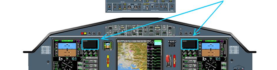


3 Falcon 900EX Easy [Electrical Summary] FLIGHT DECK OVERVIEW Page 2
4 SOURCES INTERNAL EXTERNAL DC SOURCES - two 36 Ah Ni-Cad batteries - three 9 kw (300 A) enginedriven starter generators - one 9 kw (300 A) APU-driven starter generator (ground operation only) - 1 Secondary Flight Display (SFD) battery: HORIZ BAT - 1 auxiliary battery: AUX BAT (option) - 3 batteries for the emergency lighting system - 4 buffer batteries for LH DU, UP DU, MAU1 and MAU2-4 NIC batteries, one battery per NIC/PROC module of each MAU - Ground Power Unit (GPU) AC SOURCES - equipment requiring alternating current are equipped with built-in inverters - passenger convenience items can be powered by inverters on a dedicated network Page 3
5 EQUIPMENT LOCATION FWD EQUIPMENT LOCATION Page 4
6 GENERATION MAIN BATTERIES On ground, prior to APU starting, the two 24 V (36 Ah) Ni-Cad batteries provide the primary source of DC power to the entire distribution system and they supply electrical power to start the engines. As soon as one generator is connected, batteries are reloading and flatten generator electrical spikes. They are also capable of an emergency in-flight source of power for a limited period if all engine-driven generators fail. In that case, battery autonomy would be around 56 min with maximum load shedding. The batteries are located in the mechanic servicing compartment accessible through the mechanic servicing compartment door. The batteries are ventilated, on the ground, by a battery powered blower and by aerodynamic air flow in flight. During ground operation, the battery blower is operational when the BAT 2 switch is on. NOTE The two batteries are necessary for engine starting. Very weak batteries cannot be connected to the main buses, as their contactors need at least 18 V DC to close. OTHER BATTERIES Three batteries supply emergency lights. One HORIZ BAT battery supplies Secondary Flight Display (SFD), for approximately 2 h 40 min, in case of total electric failure. One AUX BAT battery, when installed, supplies dedicated equipment during electrical failure. Four MAU-DU BAT buffer batteries supply prevent the LH display, UP display, MAU1 and MAU2 so as to prevent them from diming when the APU or engines starts due to voltage drop. One of these batteries supplies the Centralized Maintenance Computer (CMC) during shutdown. Four NIC batteries supply NIC/PROC module of each MAU chanel. Except for the emergency lights batteries and NIC batteries, all batteries voltages are monitored and indicated in the TEST synoptic page. The emergency lights batteries can be checked by a three-position OFF-ON-ARM EMERG LIGHTS switch located on the overhead panel. ENGINE DRIVEN GENERATORS Engine-driven starter-generators are driven by the accessory gear box of each engine. A shear shaft in the generator prevents damages to the accessory gearbox in case of generator seizure. A damper in the generator shaft prevents from vibrations. Page 5
 is equipped with the same starter-generator as the engines.")
 provide current and voltage regulation and protection for their associated generator: - Regulation: the GCU regulates the voltage at 28.")
7 They are rated at 9 kw and regulated at 28.5 V DC by their associated Generator Control Unit (GCU). APU GENERATOR The Auxiliary Power Unit (APU) is equipped with the same starter-generator as the engines. While the airplane is on the ground, it is capable of power the entire DC electrical system, in addition to charge batteries and providing engine start assistance. GCU The four Generator Control Units (GCU) provide current and voltage regulation and protection for their associated generator: - Regulation: the GCU regulates the voltage at 28.5 V DC and monitors the output current to 300 A, with a maximum of 350 A for one minute. It also provides generator output regulation in order to balance the current between several generators, when connected in parallel on the same bus. - Protection: the GCU automatically disconnects its associated generator in case of over voltage or electrical load limit overtaking. They also control engine start sequence. CAUTION Limit output current at 225A on ground. Limit output current at 300 A below 43,000 ft. Limit output current at 260 A above 43,000 ft. GPU An approved 28 V DC Ground Power Unit (GPU) may be used for prolonged periods to power the DC system in order to facilitate maintenance and servicing. The GPU may also be used for engine starting, but it cannot be used to charge the batteries, unless a GPU airplane battery charging system is installed. Recommended instantaneous power for engine start is 1,000 A maximum. When the GPU is connected and operating, generators and batteries are automatically disconnected from the LH and RH buses. GPU receptacle GPU RECEPTACLE LOCATION Page 6
8 DISTRIBUTION DC power distribution is separated into two independent buses, allowing redundantly powered systems to continue to safely operate if one bus fails. The distribution system consists of 8 distinct buses: - battery bus, - starting bus, - LH bus, - RH bus, - bus A1, - bus A2, - bus B1, - bus B2. ELECTRICAL SYSTEM DIAGRAM Page 7
9 The battery bus is powered as soon as one of the batteries is installed and plugged in. Regardless of battery switch position, the battery bus provides electrical directly to: - the single point refueling panel, - the emergency outboard slats control circuit, - the 3 generators excitation circuits, - Servicing lights (exterior and interior). Most of the avionics equipment are connected to the main buses through master-switches located on the overhead panel. OVERHEAD PANEL Page 8
 CCD RH (one channel) DME 2 GP RH LW DU MAU 1 channel B MAU 2 channel A MKB RH RAD ALT 2 RH DU")
10 LH BUS RH BUS AUDIO Panel 3 AFCS channel B AT servomotors Data loader LSS MAU 1 Channel A RAD ALT 1 TCAS Weather Radar ADF 1 ADM 1 ATC 1 CCD LH (one channel) CCD RH (one channel) DME 1 GP LH LH DU MAU 2 channel B MKB LH UP DU VOR 1 ADF 2 ADM 2 AFCS channel A AP servomotors ATC 2 CCD LH (one channel) CCD RH (one channel) DME 2 GP RH LW DU MAU 1 channel B MAU 2 channel A MKB RH RAD ALT 2 RH DU VHF 3 (optional) VOR 2 Yaw Damper Page 9
11 A1 LH BUS A2 CABIN PRESS CAB TEMP CONTROL Air conditioning / Oxygen COND'G CREW STBY BLEED MONIT LH O2 BOX Flight controls Hydraulic Ice and rain protection A/B CONTROL LH AUTO SLAT (Normal power) PITCH FEEL STAB EMERG HYDR 1 INDIC ST BY PUMP AIR FR LH AOA HEAT LH PITOT HEAT LH STATIC HEAT TEMP PROBE WSHLD FRONT LH AT SVO (AT servo-actuator) FLAP A/B INDIC TRIM AILERON TRIM RUDDER DRAINS HEAT DV WINDOW STBY PITOT WIPER LH Landing Gear L/G CONTROL BSCU 1 (Braking system No 1) Lights ANTICOL FIN CKPT LH READING EXT WRN LIGHTS A (Emergency lighting) LH SLATS LIGHT LIGHT WARN A-B NAV OVERHEAD LH STROBE BELTS / NO SMOKING CAB LIGHT MASTER CABIN CEILLING LANDING LH LSS (Lightening Sensor System) SHIELD TEST WARN A-B Page 10
12 A1 LH BUS A2 Navigation / communication Avionics ADF 1 ATC 1 DME 1 IRS 1 VOR 1 ADM 1 CCD LH CMPTR LH GP LH HUD-HGS/HCP HUD-CHU LH AV MASTER LH DU LH DU BAT MAU 1 BAT MAU1 CH A MKB LH STBY INSTR BAT AFCS CH B HF 1 ICS 3 ICS LH IRS 3 VHF 1 CCD RH DATA LOADER MAU 2 CH B MRC1 NIM R/T WR RAD ALT 1 REV PANEL TCAS UP DU UP DU BAT Page 11
13 A1 LH BUS A2 Engine / fuel Miscellaneous BOOST 1 DEEC 1 DETECT ENG 1 (Fire detection) ENG 1 HP 1 (HP valve) ENG 1 VIBR (Vibration) EXTING ENG 1 (Extinguisher) IGNIT AUTO (Automatic ignition, all engines) IGNTR 1 (Igniton of ENG 1) OIL 1 X-BP 2-3 (Cross BP valve) 115V AC MASTER (Transfo) AUDIO WARN A BOOSTSTRAP DEEC 3 DETECT ENG 3 ENG 3 HP 3 ENG 3 VIBR EXTING ENG 3 FUEL 2 SHUT-OFF IGNTR 3 OIL 3 STBY BOOST 2 BAG COMP (Fire detection) FLIGHT RECORDER A3: Pilot Front Windshield A4: Galley 1 Bar A5: Standby Hydraulic Pump A6: Galley 2 Bar REAR COMP (Fire detection) Page 12
14 B1 BLEED CTL HP 2 RH BUS BAG PRESS B2 Air conditioning / Oxygen Flight controls Hydraulic Ice and rain protection COND G CABIN CPCS MONIT RH O2 BOX AIL FEEL RH AUTO SLAT STAB NORMAL HYDR 2 INDIC AFT SIDE WINDOW RH AOA HEAT WIPER RH BLEED MONIT CKPT TEMP CTRL AFCS CH A AP SVO FLAP CONTROL ROLL EMERG YD (Yaw Damper) RH PITOT HEAT RH STATIC HEAT WSHLD FRONT RH L/G INDIC BSCU 2 Landing Gear LANDING RH NOSE WHL Lights CAB/LAV MASTER CKPT RH READING EXT WARN LIGHTS B (Emergency lighting) TAXI ANTICOL BELLY EMERG LIGHTS LANDING RH RH SLATS LIGHT (Leading edge ice detection) Page 13
15 B1 RH BUS B2 Navigation / communication Avionics ADF 2 ATC 2 DME 2 IRS 2 VHF 3 VOR 2 ADM 2 CCD LH CMPTR RH CREW CALL GP RH LW DU MAU 1 CH B MAU 2 BAT OVERHEAD RH RH AV MASTER AFCS CH A HF 2 ICS RH MRC 2 NIM SELCAL VHF 2 VOICE RECORDER CCD RH INSTR RH MAU 2 CH A MKB RH RAD ALT 2 RH DU Page 14
16 B1 RH BUS B2 Engine / fuel DEEC 2 DETECT ENG 2 ENG 2 VIBR ENG 2 VIBR EXTING ENG 2 IGNITR 2 NORM BOOST 2 OIL 2 STBY DEEC 1 X-BP 1-3 BOOST 3 FUEL 1 SHUT-OFF FUEL 3 SHUT-OFF FUEL TRANS 2 PRESSURE FUELING REVERSE DEPLOY REVERSE STOW REVERSE WARN X-BP 1-2 APU APU FIRE APU Miscellaneous AUDIO WARN B LEVEL CREW SEATS GALLEY MASTER B3: Copilot Front Windshield B4: spare NOSE FAN BATTERY BUS BAG COMP DOOR (baggage compartment door exterior lighting) EXCIT GEN 1 EXCIT GEN 2 Miscellaneous EXCIT GEN 3 LIGHT 1 (passenger door airstairs and aisle lighting, mechanic servicing compartment lighting, refueling connector lighting and refueling panel) LIGHT 2 (dome, nose cone and baggage compartment lighting) SLATS (emergency outboard slats) Page 15
17 CONTROL OVERHEAD PANEL DURING NORMAL FLIGHT OPERATION Page 16


 - act as reset switches when")

18 SYNTHETIC TABLE CONTROL FUNCTION TO ACTIVATE TO DEACTIVATE SYNOPTIC On: Contactor is closed and GPU is off BAT1 two positions trip magnetic switch - BAT 1 connects battery 1, through the starting bus, to the LH bus - BAT 2 connects battery 2 to the RH bus NOTE Each battery supplies directly the battery bus whatever battery switch position Connected Off: Contactor is open and {GPU is ON or APU/ENG start in progress} Abnormal situation: overheating BAT1 two positions trip magnetic switch - trip automatically to down position when system detects an anomaly (too high reverse current) - act as reset switches when the fault is cleared (only one reset attemp is allowed) Abnormal situation: contactor is closed and GPU is on Disconnected Abnormal situation: contactor is open and GPU is Off and no APU/ENG start is in progress Page 17

19 CONTROL FUNCTION TO ACTIVATE TO DEACTIVATE SYNOPTIC two positions trip magnetic switch two positions trip magnetic switch two positions trip magnetic switch - GEN 1 and GEN 3 connect generators 1 and 3 to the LH bus - GEN 2 connects generator 2 to the RH bus - trip automatically to down position when the GCU detects an over-voltage - act as reset switches when the fault is cleared (only one reset attempt is allowed) Connected Disconnected On: contactor is closed and GPU is Off Off: contactor is open and {engine is not running or GPU is On} Abnormal situation: contactor is open and engine is running and GPU is Off GEN1 Page 18


 Abnormal")

 On: airplane powered by GPU")

20 CONTROL FUNCTION TO ACTIVATE TO DEACTIVATE SYNOPTIC - connects the APU generator to the LH bus - trips automatically to down position when the GCU detects an over-voltage, - acts as a reset switch when the fault is cleared (only one reset attempt is allowed) For more information, refer to Chapter 02 / ATA 49 refer to Chapter 02 / ATA 49 On: contactor is closed and GPU is Off Off: contactor is open (APU N1 < 95% or GPU is On) Abnormal situation: contactor is open and APU N1 > 95% and GPU is Off ON GROUND ONLY: - disconnects the batteries from their respective buses, independently from BAT magnetic switch position Push On (on ground) On: airplane powered by GPU light pushbutton - ties up LH and RH buses whatever BUS TIED selector position - allows GPU to supply all buses Push Off (on ground) Off: airplane not powered by GPU Page 19
21 CONTROL FUNCTION TO ACTIVATE TO DEACTIVATE SYNOPTIC Normally tied - ties up LH and RH buses Turn horizontally (TIED) Abnormally untied (rotary switch horizontal or EXT POWER pushed on) BUS TIED rotary switch Normally untied Turn vertically (UNTIED) Abnormally tied (rotary switch vertical with no GPU) Page 20
22 CONTROL FUNCTION TO ACTIVATE TO DEACTIVATE SYNOPTIC pushbutton Push on - sheds cabin optional equipment load from the LH bus (connected) Push off No specific indication on the ELEC synoptic status light (shed) pushbutton - sheds galley optional equipment load from LH bus Push on (connected) Push off No specific indication on the ELEC synoptic status light (shed) pushbutton Push on (connected) - supplies power to LH AV equipment Push off No specific indication on the ELEC synoptic status light (shed) pushbutton Push on (connected) - supplies power to MINI LOAD equipment Push off No specific indication on the ELEC synoptic status light (shed) Page 21

23 CONTROL FUNCTION TO ACTIVATE TO DEACTIVATE SYNOPTIC Pushbutton Push on (connected) - supplies power to RH AV equipment No specific indication on the ELEC synoptic Push off status light (shed) OVERRIDE Two positions guarded switch - in the OVERRIDE position, reconnects all the systems, previously shedde after failure of one generator NORMAL No specific indication on the ELEC synoptic ARM status light Three positions switch - ARM: activates the standby mode of the three EMERG batteries - ON: illuminates EMERG lights and check their three batteries charge (normal inflight position) ON (test position) No specific indication on the ELEC synoptic OFF Page 22

24 INDICATION Electrical system indications are displayed on two pages on the MDU: - ELEC synoptic, - STAT synoptic. LH bus voltage Bus tied rotactor RH bus voltage Generators and batteries contactors STAT ENG ELEC FUEL HYD ECS BLD 28.5 V V TEST External power status BAT1 BAT2 Generators and batteries current Batteries 1 and 2 temperature ELEC SYNOPTIC EXAMPLES OF BATTERY TEMPERATURE INDICATION Warm temperature: indication displayed on amber background Hot temperature: indication displayed on red background Invalid data BATTERY TEMPERATURE INDICATION For each battery, temperature indication is given by the pointer position on an analog scale and by digital readout. Page 23
25 When the airplane is not equipped with temperature control (lead acid batteries), none of the above symbols and indication are displayed (option). The scale is colored in white below 49 C, in amber between 49 C and 71 C and in red above 71 C. EXAMPLES OF BATTERY AMMETER Normal values displayed in green Abnormal values displayed in amber Invalid data BATTERY AMMETER For each of the two batteries, current indication is given by the pointer position on an analog scale and by digital readout. The scale is colored in amber below and above + 45 A and in white between 300 A and + 45 A. NOTE A negative current designates a battery charging current. EXAMPLES OF DC GENERATOR AMMETER Normal values displayed in green Abnormal values displayed in amber DC GENERATOR AMMETER Invalid data For each of the three engine-driven generators, current indication is permanently displayed by the pointer position on an analog scale and by digital readout. Page 24
26 In flight, the scale and the indication are colored in amber when current is greater then 300 A below an altitude of 43,000ft. The threshold is 260 A for altitudes above 43,000 ft. On ground the threshold is 225 A. For the APU generator, the analog ammeter and digital readout are only displayed when the airplane is on the ground and the APU running. The scale and the indication are amber range when current overtakes 300 A. NOTE ERRONEOUS INDICATION FOR AIRPLANE WITHOUT M3706 For any generator or battery, 0 A is displayed on synoptic ammeters when real current is between -30 A and +30 A. STARTING PHASE White START is placed under the generator ammeter which is in starting mode. NOTE Amber START is used to indicate a generator that stays in starter mode when N 2 > 45%. Generator that assists has a white ASSIST annunciation. STARTING PHASE White START is placed under the APU ammeter while the APU N1 is below 50%. During engine starting phase, APU and BAT 1+2 symbols may be temporarily displayed in gray color. Page 25

27 EXAMPLES OF BUSES VOLTMETER Normal values displayed in green Abnormal values displayed in amber BUSES VOLTMETER Invalid data LH and RH buses are permanently monitored through two voltmeters displayed in the ELEC synoptic. When a generator supplies the bus, the analog scale is colored in amber below 25 V and above 30 V. This range is different depending on the airplane electrical configuration (bus supplied by batteries only, APU starting, ). NOTE Electrical information is also available on the STAT synoptic. Page 26


28 STATUS SYNOPTIC LH and RH voltage buses, BAT and GEN current indications STATUS SYNOPTIC TEST SYNOPTIC TEST SYNOPTIC To check MAU / DU BAT, AUX BAT or HORIZ BAT, place the CCD cursor on the respective soft key and keep the <ENTER> button pressed to activate the test and to have indications displayed. Normal values appear in green while too low or too high values appear in amber. Page 27
29 INTRODUCTION Feeder cables are protected by current fuses located inside the electrical box. Circuit protection is provided by conventional trip-free circuit breakers located on the circuit breakers panel. The circuit breakers panel is divided into different sections. Each section, delimited by different colored frames, corresponds to airplane major systems. In case of failure of any of the three engine-driven generators, certain items, non essential for the flight, such as galley, lavatory and cabin entertainment systems are automatically loadshed. After proper electrical load analysis by the crew, an AUTO LOAD SHED switch located on the right side ledge may be set to the OVERRIDE position to re-energize the load-shed systems. In the case of a second generator failure, the electrical system is auto load shed a second time with no possibility for the crew to re-energize the load-shed items. The auto-load shed system is disabled when the airplane is on the ground, allowing normal operation of all cabin facilities. The BUS TIED rotary switch normal position is vertical, isolating the LH and RH buses from each other. In case of overvoltage or short-circuit on one side, the other side is not affected. The LH and RH buses must be temporary tied for APU and engine starting or on the ground, when the airplane is powered by the GPU only. When LH and RH buses are tied, a 225 A fuse offers protection between them in case of overload in one bus. BATTERIES The batteries are protected against excessive load by a trip magnetic switch, which opens and disconnects the battery when the charging (reverse) current exceeds 400 A during more than 1 sec. The BAT magnetic switch trips off and BAT.. CAS message appears. NOTE Only one reset attempt is permitted. Batteries are ventilated on ground and in flight to protect them (hydrogen accumulation, heating). On ground, the ventilation is provided by an electrical blower. It operates when the BAT 2 trip magnetic switch is on and the EXT POWER pushbutton is on off position. In flight, ventilation is provided by the effect of dynamic air flowing through a venting duct and blowing on the batteries. Page 28

.")

30 GENERATORS AND APU The engine-driven generators and the APU are each monitored by a GCU. Each GCU provides: - Voltage regulation: 28.5 V DC - Main protections are: o overvoltage protection (> 32 V DC ), o current output limitations (350 A max). When the protection is activated, the corresponding magnetic switch trips off, isolating the generator. In this case, the GEN.. CAS message appears. CAUTION Do not attempt to reset more than one time. CIRCUIT BREAKERS CIRCUIT BREAKERS PANEL Page 29
31 CIRCUIT BREAKER COLOR CODE Mini load A1 and A2 BUS B1 and B2 BUS EMERG LIGHTS AIL FEEL LIGHTS WARNING A / B TEST WARN A / B To be pulled if all generators fail NOTE Red breakers are back-up powered by the LH bus or by the RH bus if LH bus is not available. Page 30

 OVERHEAD")
32 INTRODUCTION In the following, typical ground and in-flight situations have been selected to help the crew to understand the symbols provided in the various panels and displays. GROUND OPERATION WITH GPU PLUGGED (MINI LOAD MASTER ON) OVERHEAD PANEL ELEC SYNOPTIC Page 31
33 ACTION RESULT Plug in the GPU which is not running. No result Turn on GPU (at 28 V DC ) No result Overhead panel: Push on EXT PWR light pushbutton Green light on ALL MASTER: OFF lights on MINI LOAD MASTER: OFF light off After time delay of many seconds: GPU ON: BUS TIED CAS message Push on MINI LOAD MASTER Synoptic: - symbol - all GEN and BAT isolated (gray synoptic symbols) - BUS TIED amber indication - LH and RH buses voltage indications Page 32


34 GROUND OPERATION WITH APU OPERATING (LH AV, RH AV AND MINI LOAD MASTER ON) OVERHEAD PANEL ELEC SYNOPTIC Page 33
35 ACTION RESULT BAT1 and BAT2 overhead panel trip magnetic switches Up position MINI LOAD MASTER overhead panel pushbutton pushed on BUS TIED rotary switch in horizontal position EXT POWER overhead panel pushbutton Off APU MASTER pushbutton depressed (ON) APU START STOP pushbutton depressed (START) No result BAT 1,2 symbols in green LH and RH buses voltage indications GEN 1,2,3 in stand-by + symbol in gray BUS TIED symbol in green BUS TIED amber indication on the ELEC synoptic EXT POWER symbol in gray After starting: - APU symbol in green (generator connected) - BAT1 and BAT2 charging (negative current) LH and RH AV MASTER overhead panel pushbuttons pushed on LH and RH AV MASTER : OFF lights off Page 34
36 NORMAL FLIGHT OPERATION OVERHEAD PANEL ELECTRICAL SYNOPTIC Page 35
37 ACTION RESULT All overhead panel pushbuttons depressed All overhead panel trip magnetic switches on Up position BUS TIED rotary switch on vertical position (In-flight normal position) EXT POWER switch Off Unlighted GEN 1,2,3 and BAT 1,2 symbols in green + respective current indication (and temperature for batteries) indications LH and RH buses voltage indications BUS TIED symbol in gray EXT POWER symbol in gray APU MASTER pushbutton Off APU symbol in gray Page 36
38 BATTERY 1 OVERHEAT ABNORMAL STATUS OVERHEAD PANEL ELEC SYNOPTIC CONTEXT Battery 1 overheat RESULT + HOT BAT 1 CAS message Battery temperature > 71.1 C (160 F) + MASTER WARNING light on BAT 1 symbol in red + BAT 1 temperature indication in red Page 37
39 AFTER PROCEDURE COMPLETE OVERHEAD PANEL ELEC SYNOPTIC ACTION RESULT BAT 1 isolated: - BAT 1 CAS message appears BAT 1 overhead panel trip magnetic switch set to down position Wait until: - HOT BAT 1 CAS message disappears (battery temperature < 71 C) - WARM BAT 1 CAS message appears When HOT BAT 1 disappears: - BAT 1 symbol in amber + BAT 1 temperature indication in amber, decreasing Page 38
40 GEN 2 FAILURE ABNORMAL STATUS OVERHEAD PANEL ELEC SYNOPTIC CONTEXT - GEN 2 failure detected RESULT GEN 2 overhead panel trip magnetic switch automatically set to down position (isolated) and GEN 2 symbol in amber on ELEC synoptic + BAT2 voltage on RH bus GEN 2 CAS message + light on Page 39

41 AFTER PROCEDURE COMPLETE OVERHEAD PANEL ELEC SYNOPTIC ACTION RESULT - BUS TIED rotary switch set to tied position (horizontal position) + contactor symbol and BUS TIED indication on ELEC synoptic + BUS TIED CAS message NOTE In GEN 1+2 off configuration bus untied, LH bus is supplied by GEN 3 and RH bus is supplied by BAT 2. When buses are supplied only by batteries (case of bus untied), green voltage scale is downshifted (22 V gren scale 29 V). Page 40
 the faulty generator, GEN 1, remains on line + BUS LH OVERVOLTAGE CAS message + light on")
42 NO PROTECTED GEN 1 OVERVOLTAGE (>32 V DC ) ABNORMAL STATUS OVERHEAD PANEL ELEC SYNOPTIC CONTEXT RESULT High voltage detected on LH bus (33 V DC ) the faulty generator, GEN 1, remains on line + BUS LH OVERVOLTAGE CAS message + light on Page 41


43 AFTER PROCEDURE COMPLETE OVERHEAD PANEL ELEC SYNOPTIC ACTION RESULT GEN 1 overhead panel trip magnetic switch set to down position - GEN 1 isolated and GEN 1 symbol in amber on ELEC synoptic + GEN 1 CAS message + light on Page 42
44 CAS MESSAGES CAS MESSAGE 3 GEN S FAIL HOT BAT.. BAT.. BAT.. TEMP INOP BUS TIED BUS XX LOW VOLTAGE DEFINITION All generators (1, 2 and 3) disconnected and all engines running (N2 above 45%) Battery (1/2) temperature at or above 71.1 C (160 F) Battery (1/2) not connected and no GPU power supply On ground, battery (1/2) temperature sensor failure Indication of untimely bus tied (LH/RH) bus voltage lower than 24 V. with one generator connected BUS XX OVERVOLTAGE (LH/RH) bus voltage over 32 V. GEN.. OVHD BACKUP PWR XX FAIL WARM BAT.. BAT.. COLD BAT.. TEMP INOP BUS TIED GEN.. FAIL GPU ON: BUS TIED OVHD BACKUP PWR.. FAIL Generator (1,2 or 3) failed to connect and corresponding engine running (N2 above 45%) On ground, overhead panel channel is operating on backup power supply (LH/RH) Battery (1/2) temperature at or above 48.9 C (120 F) Battery (1/2) temperatue < 4 F (-30 C) In-flight, battery (1/2) temperature sensor failure Indication of bus tied On ground, indication of generator (1,2 or 3) failure (corresponding engine shut-down) Airplane powered by GPU: LH and RH buses tied, independently of rotary switch position In-flight, indication of failure of backup power supply for overhead panel Page 43
ATA 24 ELECTRICAL POWER
 F900EX EASY 02-24-00 CODDE 1 PAGE 1 / 2 TABLE OF CONTENTS 02-24 02-24-00 TABLE OF CONTENTS 02-24-05 GENERAL Introduction Sources Equipment location 02-24-10 DESCRIPTION Generation Distribution 02-24-15
DASSAULT AVIATION Proprietary Data
 F2000EX EASY 02-24-00 CODDE 1 PAGE 1 / 2 TABLE OF CONTENTS 02-24 02-24-00 TABLE OF CONTENTS 02-24-05 GENERAL Introduction Sources Equipment location 02-24-10 DESCRIPTION Generation Distribution Operation
DASSAULT AVIATION Proprietary Data
 F2000EX EASY 02-49-00 CODDE 1 PAGE 1 / 2 TABLE OF CONTENTS 02-49 02-49-00 TABLE OF CONTENTS 02-49-05 GENERAL Introduction Sources Equipment location 02-49-10 DESCRIPTION Introduction Description Operating
Cessna Citation XLS - Electrical
 GENERAL Electrical power for the Citation XLS comes primarily from DC sources originating with the starter/ generators, the Auxiliary Power Unit (APU) or the battery. A receptacle below the left engine
ATA 36 PNEUMATIC TABLE OF CONTENTS DGT ATA 36 PNEUMATIC TABLE OF CONTENTS GENERAL Introduction Sources
 F900EX EASY 02-36-00 CODDE 1 PAGE 1 / 2 TABLE OF CONTENTS 02-36 02-36-00 TABLE OF CONTENTS 02-36-05 GENERAL Introduction Sources 02-36-10 DESCRIPTION Introduction Main sub-systems Distribution 02-36-15
ATA 49 AUXILIARY POWER UNIT
 F900EX EASY 02-49-00 CODDE 1 PAGE 1 / 2 TABLE OF CONTENTS 02-49 02-49-00 TABLE OF CONTENTS 02-49-05 GENERAL Introduction Sources APU location 02-49-10 DESCRIPTION Introduction Description Operating principle
DASSAULT AVIATION Proprietary Data
 F2000EX EASY 02-28-00 CODDE 1 PAGE 1 / 2 TABLE OF CONTENTS 02-28 ATA 28 - FUEL SYSTEM 02-28-00 TABLE OF CONTENTS 02-28-05 GENERAL Introduction Sources Fuel tank location 02-28-10 DESCRIPTION Sub-systems
DASSAULT AVIATION Proprietary Data
 F900EX EASY 02-30-00 CODDE 1 PAGE 1 / 2 TABLE OF CONTENTS 02-30 02-30-00 TABLE OF CONTENTS 02-30-05 GENERAL Introduction Anti-icing protection sources Anti-ice system location overview 02-30-10 DESCRIPTION
DASSAULT AVIATION Proprietary Data
 F2000EX EASY 02-33-00 CODDE 1 PAGE 1 / 2 TABLE OF CONTENTS 02-33 02-33-00 TABLE OF CONTENTS 02-33-05 GENERAL Introduction Sources 02-33-10 DESCRIPTION General Cockpit lights Cabin lights Servicing lights
SECTION 2-05 ELECTRICAL
 SECTION 2-05 TABLE OF CONTENTS Block General...2-05-05...01 DC System...2-05-05...02 DC System Protection...2-05-05...04 External Power Source...2-05-05...05 Batteries...2-05-05...06 Backup Battery...2-05-05...07
B777. Electrical DO NOT USE FOR FLIGHT
 B777 Electrical DO NOT USE FOR FLIGHT 6.10 Electrical-Controls and Indicators Electrical Panel [IFE/PASS SEATS and CABIN/UTILITY switches basic with C/L 350] 1 2 IFE/PASS CABIN/ SEATS UTILITY 3 11 APU
DASSAULT AVIATION Proprietary Data
 F2000EX EASY 02-27-00 CODDE 1 PAGE 1 / 2 TABLE OF CONTENTS 02-27 02-27-00 TABLE OF CONTENTS 02-27-05 GENERAL Introduction Flight control sources Primary and secondary flight controls 02-27-10 DESCRIPTION
CHAPTER 6 ELECTRICAL SYSTEMS
 CHAPTER 6 ELECTRICAL SYSTEMS Page TABLE OF CONTENTS 06-00-01/02 DESCRIPTION General 06-10-01 Description 06-10-01 Controls and Indicators 06-10-02 COMPONENTS Circuit Breaker Panel Locations 06-20-01/02
OVERHEAD PANEL PROCEDURES FLASH CARDS
 OVERHEAD PANEL PROCEDURES FLASH CARDS Boeing 737-800 A supplement to the procedures and checklists publication, Flying the Boeing 737-800 NG Greg Whiley Aussie Star Flight Simulation ELECTRICAL POWER UP
CHAPTER ICE AND RAIN PROTECTION SYSTEM
 15--00--1 ICE AND RAIN PROTECTION SYSTEM Table of Contents REV 3, May 03/05 CHAPTER 15 --- ICE AND RAIN PROTECTION SYSTEM Page TABLE OF CONTENTS 15-00 Table of Contents 15--00--1 INTRODUCTION 15-10 Introduction
24 ELECTRICAL DC ELECTRICAL SYSTEM DESCRIPTION
 24 ELECTRICAL DC ELECTRICAL SYSTEM DESCRIPTION The Direct Current electrical system provides power to most equipment through an electrical bus system. The power may be supplied from one of three sources:
DASSAULT AVIATION Proprietary Data
 F900EX EASY 02-27-00 CODDE 1 PAGE 1 / 2 TABLE OF CONTENTS 02-27 02-27-00 TABLE OF CONTENTS 02-27-05 GENERAL Introduction Flight control sources Primary and secondary flight controls 02-27-10 DESCRIPTION
Bombardier Global Express - Hydraulics
 INTRODUCTION Hydraulic power is provided by three independent and isolated systems designated 1, 2 and 3 and operate at a nominal pressure of psi. SYSTEM 1 AND 2 Systems 1 and 2 are each powered by an
DASSAULT AVIATION Proprietary Data
 FALCON 7X 02-28-05 CODDE 1 PAGE 1 / 4 GENERAL ACRONYMS APU BP CAS CB CCD CG ECP FCP FLCU FMS FQMC FQ FQMS FR Fuel SOV IRS LP OP PCB PDU POF PPH RCP SSPC Auxilary Power Unit Booster Pump Crew Alerting System
Canadair Regional Jet 100/200 - Auxiliary Power Unit
 1. INTRODUCTION The auxiliary power unit (APU) is installed within a fireproof titanium enclosure in the aft equipment compartment. The APU is a fully automated gas turbine power plant which drives an
Dash8 - Q400 - Pneumatics
 12.19.1 Introduction The Auxiliary Power Unit (APU) replaces the standard composite tailcone with a titanium tailcone and firewall. The APU is accessed by two clamshell type doors on the bottom of the
SECTION IV ELECTRICAL & LIGHTING
 SECTION IV ELECTRICAL & LIGHTING TABLE OF CONTENTS Electrical Power Systems... 4-1 Introduction... 4-1 General... 4-1 Main Batteries... 4-2 Emergency Battery... 4-3 Generators... 4-4 Generator Control
AIRPLANE GENERAL Exterior REV 3, May 03/05
 Vol. 1 01--20--1 AIRPLANE GENERAL Exterior REV 3, May 03/05 24 ft 1 in (7.34 m) 5ft1in(1.55m) 10 ft 7 in (3.23 m) 6ft4in (1.93 m) 81 ft 6 in (24.85 m) 9ft6in(2.89m) 8ft10in (2.69 m) 36 ft 4 in (11.07 m)
POWER ON CHECK LIST COCKPIT PREPARATION
 Normal Check List DASH 8-402 1 POWER ON CHECK LIST CIRCUIT BREAKERS... CHECKED BATTERY MASTER... ON BATTERIES... ON MAIN BUS TIE... TIED EXTERNAL POWER... AS REQUIRED APU... AS REQUIRED BATTERIES & BATTERY
General. APU Control System. APU Door System
 .10 -Description and Operation General The Auxiliary Power Unit () provides electrical and pneumatic power for engine start and air conditioning, and supplies ground and in-flight electrical power. Pneumatic
DASSAULT FALCON 7X SYSTEMS SUMMARY
 DASSAULT FALCON 7X SYSTEMS SUMMARY Airframe & Doors This material is to be used for training purpose only Do not use it for flight! Please note that this document is not affiliated in any way with any
King Air B90. Speeds (KIAS)
") King Air B90 Speeds (KIAS) V MCA 92 V SSE (101) Derived from C90 V X 101 V Y 114 Down to 103 @ 30 000 V XSE 101 V YSE 110 Down to 101 @ 24 000 V A 169 V R 92 V 1 101 V MO 208 V FE 174 35% 130 100% V LE
King Air B90 Speeds (KIAS) V MCA 92 V SSE (101) Derived from C90 V X 101 V Y 114 Down to 103 @ 30 000 V XSE 101 V YSE 110 Down to 101 @ 24 000 V A 169 V R 92 V 1 101 V MO 208 V FE 174 35% 130 100% V LE
Introduction. APU Location
 B737 NG APU Introduction The auxiliary power unit (APU) is a self contained gas turbine engine installed within a fireproof compartment located in the tail of the airplane. The APU supplies bleed air for
REFERENCE: 2861 wings 2044 trunk 4904 total BEW 10,655 BOW 11,185 Max Useful load 5115 MLanding ZFW FUEL BURNS 11min min min
 REFERENCE: 2861 wings 2044 trunk 4904 total BEW 10,655 BOW 11,185 Max Useful load 5115 MLanding 15700 ZFW 13000 FUEL BURNS 11min 357 27min 730 36 min 940 58min 1453 1:17 1800 2:20 2933 2:46 3283 3:00 3600
Pneumatic Air Conditioning System Citation, Citation I
 Pneumatic Air Conditioning System Citation, Citation I COCKPIT VENT FOOT WARMER OVERHEAD COCKPIT WINDSHIELD WEMAC OPTIMAL VENT OVERHEAD CONDITIONED AIR DUCTS BLOWER SIDE WINDOW UNDER FLOOR CONDITIONED
DASSAULT AVIATION Proprietary Data
 F2000EX EASY 02-70-00 CODDE 1 PAGE 1 / 2 TABLE OF CONTENTS 02-70 02-70-00 TABLE OF CONTENTS 02-70-05 GENERAL Introduction Sources Engine location 02-70-10 DESCRIPTION Introduction Major components Operating
MAJESTIC Q400 SHARED COCKPIT FLOWS CHECKLISTS MULTIPLAYER OPERATIONS.
 PRE LOAD IN Agree on Ports, Share IP and select who will be doing W&B. INITIAL LOAD IN On 1 System transfer Weight and Balance to Simulator Pause Simulation Save Flight as normal FSX Flight Transfer Save
B737 NG Anti Ice & Rain
 B737 NG Anti Ice & Rain Introduction Thermal anti-icing (TAI), electrical anti-icing, and windshield wipers are the systems provided for ice and rain protection. The anti-ice and rain systems include:
Cessna Citation XLS - Anti-Ice & De-Ice Systems
 GENERAL The airplane utilizes a combination of engine bleed air, electrical heating elements and pneumatic boots to accomplish anti-ice/deice functions. The anti-ice system consists of bleed air heated
BEFORE START & START (C/R)
") IHJ 15 April 2013 1 BEFORE START & START (C/R) Chocks, Pins, Plugs... Removed Blade Position... 45 Deg Doors... Locked Seats, Pedals, Harnesses.. Adjusted & secure Parking Brake... Re-set Servo Switches...
IHJ 15 April 2013 1 BEFORE START & START (C/R) Chocks, Pins, Plugs... Removed Blade Position... 45 Deg Doors... Locked Seats, Pedals, Harnesses.. Adjusted & secure Parking Brake... Re-set Servo Switches...
SUPER KING AIR B200C Registration : PK - YGT Total Time : 9116
 CHAPTER 21 1 210101 21,010 AMM 21-10-00 L/H Flow Control Unit 101-380025-21 UNK O/C 9112 2-Oct-14 7333 0 0 0 - - - - - - 2 210106 21,050 L/H Flow Control Pneumostat 101-380013-3 UNK O/C 0 0 0 - - - - -
CHAPTER 12. Page TABLE OF CONTENTS /02 DESCRIPTION. General Description Controls and Indicators COMPONENTS
 CHAPTER 12 HYDRAULIC POWER Page TABLE OF CONTENTS 12-00-01/02 DESCRIPTION General 12-10-01 Description 12-10-01 Controls and Indicators 12-10-02 COMPONENTS Hydraulic System Block Diagram 12-20-01/02 CONTROLS
canaaair chaiiencjer
 canaaair chaiiencjer AUXILIARY POWER UNIT (APU) TABLE OF CONTENTS Subject Page GENERAL APU CONTROL START SYSTEM SHUTDOWN I BLEED AIR SYSTEM OIL SYSTEM 1 1 3 5 5 7 Figure Number LIST OF ILLUSTRATIONS Title
Pilot's Operating Handbook Supplement AS-03
 POH / AFM SECTION 9 Pilot's Operating Handbook Supplement ASPEN EFD1000 PFD This supplement is applicable and must be inserted into Section 9 of the POH when the Aspen Avionics Evolution Flight Display
ICE AND RAIN PROTECTION TABLE OF CONTENTS CHAPTER 14
 ICE AND RA PROTECTI TABLE OF CTENTS CHAPTER 14 Page TABLE OF CTENTS DESCRIPTI General Bleed/Anti-Ice Synoptic Components Anti-Ice Panel Ice Detection Ice Detection Indication Pneumatic Anti-Icing Cowl
Bombardier Challenger Auxiliary Power Unit
 GENERAL A Honeywell 36 150(CL) constant-speed gas turbine auxiliary power unit (APU) is installed within a fire-resistant compartment in the aft equipment bay. The APU drives a generator, providing AC
AIRPLANE FLIGHT MANUAL AQUILA AT01 AIRPLANE FLIGHT MANUAL - SUPPLEMENT AVE28 GLASS COCKPIT. equipped with ASPEN EFD1000 PFD
 SECTION 9 AIRPLANE FLIGHT MANUAL - SUPPLEMENT AVE28 GLASS COCKPIT equipped with ASPEN EFD1000 PFD This AFM supplement is applicable and must be inserted into Section 9 of the Airplane Flight Manual when
Canadair Regional Jet 100/200 - Fuel System
 1. INTRODUCTION The fuel system consists of three integral tanks within the wing box structure. Ejector pumps and electrical boost pumps supply fuel to each engine. The fuel system also provides facilities
CHAPTER ELECTRICAL
 Vol. 07--00-- ELECTRICAL Table of Contents REV, May 0/05 CHAPTER 7 --- ELECTRICAL Page TABLE OF CONTENTS 07-00 - Table of Contents 7--00-- INTRODUCTION 07-0 - Introduction 7--0-- AC ELECTRICAL SYSTEM 07-0
ATR OVERHAUL/REPAIR CAPABILITY LIST
 OVERHAUL/REPAIR CAPABILITY LIST Effective: 5/2/2018 repairs@usaerospacecorp.com Page 1 of 8 011232 Fan, Recirculation 011232-100 Fan, Recirculation 011232-500 Fan, Recirculation 011260 Fan, Air Extraction
Examen Teórico sobre Habilitación de Tipo B (Última actualización: Septiembre 2016)
") DIRECCIÓN GENERAL DE AERONÁUTICA CIVIL DEPARTAMENTO SEGURIDAD OPERACIONAL SUBDEPARTAMENTO LICENCIAS Examen Teórico sobre Habilitación de Tipo B-737-300 (Última actualización: Septiembre 2016) Materia:
DIRECCIÓN GENERAL DE AERONÁUTICA CIVIL DEPARTAMENTO SEGURIDAD OPERACIONAL SUBDEPARTAMENTO LICENCIAS Examen Teórico sobre Habilitación de Tipo B-737-300 (Última actualización: Septiembre 2016) Materia:
FUEL MODEL 750 BAGGAGE COMPARTMENT SMOKE DETECTION
 MODEL 750 SECTION II AIRPLANE AND SYSTEMS System test is accomplished by turning the cockpit rotary test switch to FIRE WARN. Proper system operation is indicated by illumination of the APU FIRE indicating
1. Aircraft General (0 Hours 39 minutes) 2. Doors (0 Hours 33 minutes) 3. EFIS (2 Hours 55 minutes) 4. Exterior Lighting (0 Hours 24 minutes)
 2. Doors (0 Hours 33 minutes) 3. EFIS (2 Hours 55 minutes) 4. Exterior Lighting (0 Hours 24 minutes)") Course: CRJ900 (Pilot) Delivery Formats: Web Based or Portable Classroom Number of modules: 26 Estimated Course Time: 36 Hours 16 minutes The following topics are included in this CRJ900 (Pilot) CBT/WBT
Course: CRJ900 (Pilot) Delivery Formats: Web Based or Portable Classroom Number of modules: 26 Estimated Course Time: 36 Hours 16 minutes The following topics are included in this CRJ900 (Pilot) CBT/WBT
The Straight Word. Cessna 208 Caravan 208 Caravan I & 208B Grand Caravan Series
 The Straight Word Cessna 208 Caravan 208 Caravan I & 208B Grand Caravan Series I. FLIGHT PROCEDURES: COCKPIT PREPARATION Fuel Tank Selectors Ignition Switch Heading Bug HSI Course Indicator Altimeters
2007 A119 Koala Price: Make an Offer
 2007 A119 Koala Price: Make an Offer Aircraft Details Manufacture Date: 2007 Hours: 87hrs Airframe: Aluminium alloy & bonded panel fuselage Semimonocoque aluminium alloy tail boom Skid type landing gear
This chapter contains information on DC Generation, External Power, and Electrical Load Distribution.
 CIRRUS AIRPLANE MAINTENANCE MANUAL Electrical Power CHAPTER 24-00: ELECTRICAL POWER GENERAL 24-00: ELECTRICAL POWER 1. General This chapter contains information on DC Generation, External Power, and Electrical
EXAMEN POR MATERIAS PARA USO DE LOS POSTULANTES A LA HABILITACIÓN DE TIPO EN MATERIAL B733. ENERO 2018
 DEPARTAMENTO SEGURIDAD OPERACIONAL SUBDEPARTAMENTO LICENCIAS SECCIÓN EVALUACIONES EXAMEN POR MATERIAS PARA USO DE LOS POSTULANTES A LA HABILITACIÓN DE TIPO EN MATERIAL B733. ENERO 2018 Cantidad de Preguntas
SYSTEM LOAD CHARTS AND BUS SCHEMATICS
 SYSTEM LOAD CHARTS AND BUS SCHEMATICS 1. GENERAL The airplane is equipped with a two alternator system, with each alternator operating continuously. Serials 22-0002 thru 22-1601, 22-1603 thru 22-1820,
CHAPTER 11. Page TABLE OF CONTENTS /02 DESCRIPTION. General Description Controls and Indicators
 CHAPTER 11 FUEL SYSTEM Page TABLE OF CONTENTS 11-00-01/02 DESCRIPTION General 11-10-01 Description 11-10-01 Controls and Indicators 11-10-02 COMPONENTS (NOT USED) CONTROLS AND INDICATORS 11-30-01 FUNCTIONAL
Central Warning Systems
 CIRRUS AIRPLANE MAINTENANCE MANUAL Central Warning Systems CHAPTER 31-50: CENTRAL WARNING SYSTEMS GENERAL 31-50: CENTRAL WARNING SYSTEMS 1. General This section describes the Indicating/Recording Systems
Differences Training
 Differences Training 747-400 Preamble The purpose of this presentation is to familiarize the crew with the various differences in procedures and systems among the 747-400 Fleet. The presentation highlights
CHAPTER FUEL SYSTEM
 Vol. 1 13--00--1 FUEL SYSTEM Table of Contents REV 3, May 03/05 CHAPTER 13 --- FUEL SYSTEM Page TABLE OF CTENTS 13-00 Table of Contents 13--00--1 INTRODUCTI 13-10 Introduction 13--10--1 FUEL STORAGE 13-20
AIRPLANE OPERATIONS MANUAL SECTION 2-15
 SECTION 2-15 TABLE OF CONTENTS Block General... 2-15-05..01 Bleed Air Thermal Anti-Icing System... 2-15-10..01 Wing, Stabilizer and Engine Anti-icing Valves Operational Logic... 2-15-10..04 EICAS Messages...
AW 169 Commercial in Confidence AW 169 VIP CONFIGURATION Airframe Transmission Drive System and Hydraulic System Electrical Systems
 AW 169 VIP Year of Manufacture 2017 Airframe Total Time Brand new Configuration VIP Engines PW210A Availability July 2017 LHD Warranty 3 years / 2000 hours CONFIGURATION Airframe Airframe structure including
FLIGHT CONTROLS TABLE OF CONTENTS CHAPTER 10
 TABLE OF CONTENTS CHAPTER 10 Page TABLE OF CONTENTS DESCRIPTION Primary Flight Controls Secondary Flight Controls Spoiler System Trim Control High Lift Devices Stall Protection Hydraulic Power Distribution
Doors Four outward-opening cabin doors are provided, two on each side of the fuselage. For use and operation see subsection DOORS.
 AIRFRAME AND SYSTEMS Introduction The Fokker 50 is a twin-engined, pressurized, high-wing aircraft, designed for short or medium-haul operations. Principal dimensions and limitations are given in the applicable
CARENADO COPYRIGHTS. Normal & Emergency Checklist
 NORMAL PROCEDURES CHECKLIST PREFLIGHT CHECK Control wheel -- RELEASE BELTS Avionics -- OFF Master Switch -- ON Fuel quantity gauges -- CHECK Master switch -- OFF Ignition -- OFF Exterior -- CHECK FOR DAMAGE
PROSIM 737 Overhead Panel Switchmap (July 2012)
") PROSIM 737 Overhead Panel Switchmap (July 2012) This Is How I Have Wired Up My Overhead To Work With Prosim. I have used 3 x BU0836X Boards for the inputs Why? Not because I think they are better than
PROSIM 737 Overhead Panel Switchmap (July 2012) This Is How I Have Wired Up My Overhead To Work With Prosim. I have used 3 x BU0836X Boards for the inputs Why? Not because I think they are better than
Landing Gear & Brakes
 EMBRAER 135/145 Landing Gear & Brakes GENERAL The EMB-145 landing gear incorporates braking and steering capabilities. The extension/retraction, steering and braking functions are hydraulically assisted,
Diamond DA40 TDI OH-STL
 Diamond DA40 TDI OH-STL NORMAL, EMERGENCY AND ABNORMAL CHECKLISTS PREFLIGHT INTERIOR + EXTERIOR. 1 Check Aircraft papers 2 Remove pitot cover 3 Check interior for foreign objects 4 Check flight controls
General. Airfoil Anti-Ice System
 General Ice.10 Ice and Rain Protection-Description and Operation Ice and rain protection consists of: Airfoil (wing and tail) anti-ice systems. Engine cowl anti-ice system. Air data heater system (pitot,
24-00 ELECTRICAL POWER
 ELECTRICAL POWER 1. GENERAL This chapter contains information on DC Generation, External Power, and Electrical Load Distribution. The airplane is equipped with a two-alternator, two-battery, 28-volt direct
BALLAST UNIT Ea 5 New REPAIRABLE INDICATOR FLAP POSITION Ea 1 Overhauled ROTABLE
 Part Number Description UoM Qty Condition Aircraft type Aircraft type Part Class 05939-108 BALLAST UNIT Ea 5 New REPAIRABLE 07311P000-02 BALLSCREW Ea 1 Overhauled B737-; B737-800 10-60791-13 INDICATOR
SECTION I GENERAL DESCRIPTION
 SECTION I GENERAL DESCRIPTION TABLE OF CONTENTS Aircraft General Description... 1-1 Airplane Three-View (Figure 1-1)... 1-2 General Arrangement Exterior (Figure 1-2)... 1-3 Cabin Entry Door... 1-5 Entry
39 - EFFECTIVE PAGES. Beechcraft Corporation PAGE 1 AUG 01/17 99 ILLUSTRATED PARTS CATALOG DATE CH-SECT-FIG
 CH-SECT-FIG PAGE NO. DATE CH-SECT-FIG PAGE NO. DATE 39 - CONTENTS 1 39-10-10 0 39-10-10 1 39-10-10 2 39-10-20 0 39-10-20 1 39-10-20 2 39-10-20 3 39-10-20 4 39-10-20 5 39-10-20 6 39-10-30 0 39-10-30 0A
CHAPTER 1 AIRCRAFT GENERAL
 CHAPTER 1 AIRCRAFT GENERAL INTRODUCTION This manual provides a description of the major airframe and engine systems in the Cessna Citation Mustang (Figure 1-1). This material does not supersede, nor is
by Greg Whiley Aussie Star Flight Simulation
 Flying the BAe 146 200/300 Version 2 by Greg Whiley Aussie Star Flight Simulation INTENTIALLY LEFT BLANK Greg Whiley Aussie Star Flight Simulation 2 Version Date Revision Version 1.0 25 June 2014 Original
Dash8-200/300 - Auxiliary Power Unit APU CONTROLS AND INDICATORS. Page 1
 APU CONTROLS AND INDICATORS Page 1 APU control and indicators Page 2 closed APU controls and indicators Page 3 SYSTEM DESCRIPTION General The auxiliary power unit (APU) is a gas turbine engine, located
LAD Inc. Beechcraft King Air 200 Series Technical Ground School Syllabus Material Covered
 Topic Introduction Description Structures ATA 05 Technical Publications ATA 05 Aircraft Handling ATA 12 LAD Inc. Beechcraft King Air 200 Series Technical Ground School Syllabus Material Covered Course
PA32-RT LANCE II CHECKLIST
 PA32-RT LANCE II CHECKLIST 6815.10.1112 1 Normal Procedures PREFLIGHT CHECK Control Wheel... RELEASE BELTS Parking brake... Set Master Switch... ON Fuel Quantity Gauges... check Master Switch... OFF Ignition...
GENERAL The Honeywell model TFE731-40AR turbofan engine is a lightweight, two-spool, geared-stage, front-fan, jet engine.
 ENGINE GENERAL The Honeywell model TFE731-40AR turbofan engine is a lightweight, two-spool, geared-stage, front-fan, jet engine. The cross section of the engine is shown in Figure 7-71-1, page VII-71-3.
canadair chzflleriqer OPERATING MANUAL PSP 601A-6 SECTION 5 AUXILIARY POWER UNIT (APU)
") OPERATING MANUAL. AUXILIARY POWER UNIT (APU) 1.. 3. 4. 5. 6. GENERAL APU CONTROL START SYSTEM SHUTDOWN BLEED AIR SYSTEM OIL SYSTEM TABLE OF CONTENTS Page 1 3 3 Figure Number LIST OF ILLUSTRATIONS Title
OPERATING MANUAL. AUXILIARY POWER UNIT (APU) 1.. 3. 4. 5. 6. GENERAL APU CONTROL START SYSTEM SHUTDOWN BLEED AIR SYSTEM OIL SYSTEM TABLE OF CONTENTS Page 1 3 3 Figure Number LIST OF ILLUSTRATIONS Title
CHAPTER 14 LANDING GEAR
 CHAPTER 14 LANDING GEAR Page TABLE OF CONTENTS 14-00-01/02 DESCRIPTION General 14-10-01 Description 14-10-01 Controls and Indicators 14-10-04 COMPONENTS Nose Gear 14-20-01 Main and Center Gear 14-20-02
Dornier 328Jet - Pneumatic
 ECS Control Panel Page 1 MESSAGE (SYNOPTIC) WARN INHIBIT CONDITION Location (COLOR) TONE 1 2 3 APU BLEED LEAK CAS Field (AMBER) X X LEAK (APU BLEED) Bleed air leak in APU bleed air duct. ECS Page (AMBER)
PA , Model E Normal Checklist (04/15/11)
") PA-23-250, Model E Normal Checklist (04/15/11) Key Airspeeds IAS-MPH V NE 249 V NO 198 V LO/LE 150 V A (At max gross weight.) 149 Speed for single engine cruise. 138 V FE Quarter Flaps 160 Half Flaps 140
PA-23-250, Model E Normal Checklist (04/15/11) Key Airspeeds IAS-MPH V NE 249 V NO 198 V LO/LE 150 V A (At max gross weight.) 149 Speed for single engine cruise. 138 V FE Quarter Flaps 160 Half Flaps 140
Aeroplane Aerodynamics and Flight Controls 1 2
 11.1 Theory of Flight 11.1.1. Aeroplane Aerodynamics and Flight Controls 1 2 Operation and effect of: roll control: ailerons and spoilers, pitch control: elevators, stabilators, variable incidence stabilisers
CHAPTER 3 CREW COMPARTMENT TABLE OF CONTENTS
 CHAPTER 3 CREW COMPARTMENT TABLE OF CONTENTS INTRODUCTION... 5 PILOT'S STATION... 5 General... 5 Pilot's Seat... 5 Cyclic Stick... 6 Cyclic Grip... 6 Collective... 6 Co-Pilot's Station... 7 INSTRUMENT
EC135 T2e/P2e Technical Data 2013
 EC135 T2e/P2e Technical Data 2013 135 T2e/P2e Technical Data EC135 T2e/P2e (Civil Version) EC635 T2e/P2e (Military Version) Technical Data 3 Baseline Aircraft Definition GENERAL Energy absorbing fuselage
SECTION III HYDRAULICS & LANDING GEAR
 TABLE OF CONTENTS Pilot s Manual SECTION III HYDRAULICS & LANDING GEAR Hydraulic System... 3-1 Firewall Shutoff Valves... 3-2 Source Selector Valve... 3-2 AUX HYD Pump Control... 3-2 Main/Auxiliary System
CESSNA SECTION 4. Unless otherwise noted, the following speeds are based on a maximum weight of 2550 pounds and may be used for any lesser weight.
 CESSNA SECTION 4 INTRODUCTION Section 4 provides procedures and amplified instructions for normal operations using standard equipment. Normal procedures associated with optional systems can be found in
DASSAULT AVIATION Proprietary Data
 FALCON 7X 02-70-05 CODDE 1 PAGE 1 / 6 GENERAL ACRONYMS LIST ACOC AGB APU A/T ATSV BOV CAS CB CL CMC CR DC DCU ECS EEC FADEC FBW FCU FF FOHE FSOV HP HPC HPT IGV ITT LP LPC LPT LRU MV N1 N2 PDU PLA PMA PMU
P68 Observer 2 STANDARD EQUIPMENT LIST V
 P68 Observer 2 STANDARD EQUIPMENT LIST V9.03.12 P68 OBSERVER 2 IMPORTANT NOTE: this document is a general description of the aircraft equipment only. It is not a technical document and is to be used only
PA28R ARROW CHECKLIST
 PA28R ARROW CHECKLIST 2300.11.0112 1 Normal Procedures Initial PREFLIGHT CHECK General Appearance... CHECKED Position & Taxi Path... CHECKED Tie Downs, Locks, Chocks & Covers... REMOVED Cockpit Controls...UNLOCKED
AIRCRAFT SYSTEMS PNEUMATIC
 Intentionally left blank PRELIMINARY PAGES - TABLE OF CONTENTS DSC-36-10 Description DSC-36-10-10 General GENERAL... A DSC-36-10-20 Engine Bleed System GENERAL... A Architecture... B Air Bleed Selection...C
ifly Jets: The 737NG Quick Reference Handbook Revision Number: 3 Revision Date: July 26, 2010
 ifly Jets: The 737NG ifly Jets: The 737NG Revision Number: 3 Revision Date: July 26, 2010 http://www.iflysimsoft.com/ The ifly Developer Team WARNING This manual is only used for understanding the functionalities
Bombardier Challenger Hydraulic System
 GENERAL The Challenger 605 is equipped with three independent hydraulic systems, designated as 1, 2, and 3. All systems operate at a nominal pressure of 3,000 psi to power the primary and secondary flight
TABLE OF CONTENTS FLIGHT CONTROLS. Page. 10-i
 Chapter 10: Flight Controls TABLE OF CONTENTS Page Introduction...10-1 Description...10-2 Primary Flight Controls...10-2 Secondary Flight Controls...10-4 Spoiler System...10-4 Trim Control...10-4 High
DC Generation. 1. General. A. DC Generation
 CIRRUS AIRPLANE MAINTENANCE MANUAL DC Generation CHAPTER -0: DC GENERATION GENERAL -0: DC GENERATION 1. General (See Figure -0-1) This section covers the systems to generate, regulate, control, and indicate
OPERATIONS MANUAL FTO SECTION : 06.04
 06.04.08. OO-WIK SECTION : 06.04 PARTENAVIA OO-WIK PAGE : 1 PRE ENTRY PITOT COVER - REMOVE SNOW / ICE CHECK AIRCRAFT NOSE INTO WIND AIRCRAFT WEIGHT & BALANCE WITHIN LIMITS EXTERNAL (COCKPIT FIRST) PARK
2012 Gulfstream G650 s/n 60XX
 2012 Gulfstream G650 s/n 60XX Airframe: Total Time: 2456.7 Engines: Rolls Royce BR725A1-12 (G650) 1 Engine Landings: 1190 Serial Number: 251XX EIS: March 2013 Total Time: 2456.7 Cycles: 1190 APU: Honeywell
Vso 61. Vs1 63. Vr 70. Vx 76. Vxse 78. Vy 89. Vyse. 89 (blue line) Vmc. 61 (radial redline) Vsse 76. Va 134) Vno 163
 Vmc. 61 (radial redline) Vsse 76. Va 134) Vno 163") PA34-200T Piper Seneca II Normal procedures V-speeds Knots Vso 6 Vs 63 Vr 70 Vx 76 Vxse 78 Vy 89 Vyse Vmc 89 (blue line) 6 (radial redline) Vsse 76 Va 2-36(@4507lbs 34) Vno 63 Vfe 38 (0*)/2(25*)/07(40*)
PA34-200T Piper Seneca II Normal procedures V-speeds Knots Vso 6 Vs 63 Vr 70 Vx 76 Vxse 78 Vy 89 Vyse Vmc 89 (blue line) 6 (radial redline) Vsse 76 Va 2-36(@4507lbs 34) Vno 63 Vfe 38 (0*)/2(25*)/07(40*)
NORMAL PROCEDURRES CHECKLIST PA T SENECA II PREFLIGHT CHECK INSIDE CABIN OUTSIDE CABIN
 NORMAL PROCEDURRES CHECKLIST PA-34-200T SENECA II PREFLIGHT CHECK INSIDE CABIN Avionics Master Switch -- OFF Landing Gear Control. -- DOWN Mixture Controls -- IDLE/CUTOFF Ignition Switches -- OFF Master
L 298/70 Official Journal of the European Union
 L 298/70 Official Journal of the European Union 16.11.2011 MODULE 12. HELICOPTER AERODYNAMICS, STRUCTURES AND SYSTEMS 12.1 Theory of Flight Rotary Wing Aerodynamics 1 2 Terminology; Effects of gyroscopic
CHAPTER 96 ELECTRICAL SYSTEM
 CHAPTER 96 ELECTRICAL SYSTEM Section Title Page 96-00 Description.............................................. 96.1 96-10 Battery................................................. 96.3 96-11 Lead-Acid
Cessna Citation XLS - Environmental & Temperature Control
 GENERAL Environmental and temperature control on the Citation XLS is provided by pre-cooled engine and/or APU bleed air. The conditioned bleed air is distributed in a series of ducts and vents. The primary