Doors Four outward-opening cabin doors are provided, two on each side of the fuselage. For use and operation see subsection DOORS.
|
|
|
- Magdalene Wendy Davis
- 6 years ago
- Views:
Transcription
1 AIRFRAME AND SYSTEMS Introduction The Fokker 50 is a twin-engined, pressurized, high-wing aircraft, designed for short or medium-haul operations. Principal dimensions and limitations are given in the applicable sections. Fuselage Pressurization The fuselage is pressurized in all compartments between fore and aft pressure bulkheads. An automatic pressurization system controls the outflow of conditioned air. The maximum pressure differential of approximately 5.45 PSI allows a cabin altitude of feet at a flight altitude of feet. The airconditioning packs are located in the non-pressurized aft section. Doors Four outward-opening cabin doors are provided, two on each side of the fuselage. For use and operation see subsection DOORS. Windows The flight deck windows are identified as front windows, direct-vision windows and sliding windows. The front windows are electrically heated. Rain is removed by two wipers. Directvision and sliding windows can be opened when the aircraft is not pressurized. Front and direct-vision windows are demisted by conditioned airflow. Sun visors are provided. Twentyone windows are installed on the RH side of the cabin and twenty on the LH side. The double pane construction allows a conditioned airflow for de-icing. Each cabin window is equipped with an adjustable sunblind. Probes Four pitot heads and an angle-of-attack vane are installed near the nose of the aircraft. To prevent ice build-up, they are electrically heated. Antennas and lights See the illustration for the location of antennas and external lights.
2 Wings and tail section Flight controls and flaps Each aileron has a spring tab, a balance tab, and an integral horn balance which forms part of the wing tip. The balance tab at the RH aileron can be operated as a trim tab. The vertical stabilizer is equipped with a horn-balanced rudder. The rudder is equipped with a balance tab and a trim tab. The horizontal stabilizer has two elevator surfaces and one trim tab. The flaps, which comprise two trailing edge sections of each wing, are operated hydraulically. Ice and rain protection Inflatable rubber boots are recessed into the leading edges of the wings and the tail section. De-icing is obtained by alternately inflating and deflating the air ducts in the boots. Antennas and lights See the illustrations for location of antennas and external lights. Fuel tanks Fuel is stored in two integral tanks, one in each wing, and in two collector tanks, one in each nacelle. Electrical pumps in the collector tanks ensure a continuous supply to the engines. Cross-feeding, to supply both engines from one tank, or one engine from both tanks, is possible. A pressure fuelling connector is located on the underside of the RH wing. The fuel service panel is installed in the RH nacelle. Nacelles The front section houses the power plant and its mounting. The forward bulkhead of the center section forms a firewall. The exhaust gases, led through the firewall and then outwards, exit below and slightly aft of the wing leading edge. The center section is used for housing the main landing gear and the collector tank. The rear section of the LH nacelle houses the hydraulic tank. For aircraft equipped with APU The rear section of the RH nacelle might house the Auxiliary Power Unit (APU).
3 Power plant Engines and propellers The aircraft is equipped with two wing mounted Pratt and Whitney PW 125B turboprop engines. Each engine is essentially a twin spool turbojet combined with a free power turbine assembly, which drives a reduction gearbox, and a six bladed constant speed propeller via a third concentric shaft. The propellers have reverse thrust capability for braking and ground maneuvering. Propeller pitch is controlled by high-pressure engine oil and counterweights. Feathering can be initiated automatically or manually. Engines and propellers are protected against ice by electrical heating. Both engines are equipped with fire detection and extinguishing systems. Electric, hydraulic and pneumatic power Each engine drives an Integrated Drive Generator (IDG). The IDG s generate 115V/400 Hz three phase AC power. 28 V DC power is obtained through two Transformer Rectifier Units (TRU s). Emergency power is supplied by two batteries. Electrical power for starting is supplied by the batteries and/or by an external source. Two engine driven pumps provide hydraulic power through a single system, for operation of landing gear, flaps, nose wheel steering and brakes. Bleed-air, tapped from the compressors of both engines, is used for air conditioning and pressurization, airframe de-icing and hydraulic tank pressurization. Landing gear The landing gear consists of a forward retracting nose gear and two rearward retracting main gears. Doors enclose the landing gear bays in the unpressurized fuselage nose and in each nacelle when the gear is retracted. Each gear is equipped with a shock absorber and two wheels. The main gear wheels are equipped with brake units. A skid-control system provides optimum braking for all runway conditions. The nose gear is provided with nose wheel steering and a centering system. The minimum turning radius is shown in the illustrations. The nose gear is equipped for pull out or push back operations with a tow bar. During towing, nose wheel swivel through a maximum angle of 115 degrees on either side of the center is possible. This angle is indicated by red lines painted on the underside of the fuselage. A tailskid is provided to prevent or limit structural damage to the aft aircraft structure in case of excessive nose up attitudes during take-off or landing. A taxi light is installed on the nose gear.
4 ILLUSTRATIONS Dimensions
5 Window and doors
6 Antennas 1 Weather radar 11 ADF 1 2 ATC 1 12 Glide slope 3 TCAS 13 ATC 1/2 4 VHF Com 2 14 GPS 5 Marker beacon 15 TCAS 6 DME 2 16 VHF Com 1 7 ATC 2 17 ELT (for aircraft equipped with fixed ELT) 8 DME 1 18 HF Com (for aircraft equipped with HF) 9 ADF 2 19 VOR/LOC 10 Radio altimeter
7 Exterior lights Type I 1 Taxi light 5 Navigation and strobe light 2 Wing inspection light 6 Anti-collision light 3 Landing light 7 Navigation and strobe lights 4 Anti-collision light 8 Logo lights Type II 1 Taxi light 5 Navigation and anti-collision light 2 Wing inspection light 6 Anti-collision light 3 Landing light 7 Navigation and strobe lights 4 Anti-collision light 8 Logo lights Type III 1 Taxi light 5 Navigation and anti-collision light 2 Wing inspection light 6 Anti-collision light 3 Landing light 7 Navigation and strobe lights 4 Anti-collision light 8 Not installed
8 Flight controls and flaps
9 De-icing boots
10 Landing gear
11 Turning radius
12 EQUIPMENT Flight deck Seats The flight deck is arranged for two-pilot operation. The pilot seats are adjustable horizontally (forward and backward) and vertically. Thigh support, lumbar support and recline position are individually adjustable. To facilitate entry the armrests can be folded upwards. Each seat is provided with a shoulder harness and a lap belt. A foldable seat for an observer is stowed in the flight deck entrance. The seat is provided with a shoulder harness and a lap belt. Reference eye position A horizontal line in the top corner of each pilot s instrument panel is an aid for the adjustment of the pilot s seats. For an optimum combination of outside visibility and instrument scan, the line should be seen just below the glare shield. Control column and pedals Each control wheel includes a microphone IC/RT selector, a touch-control steering button, an AP cut-out button, a chronometer button and a chart holder. The captain s control column is equipped with a stick shaker. Adjustable pedals provide for brake and rudder operation. Some aircrafts are equipped with spring-loaded footrests. Control and instrument panels Controls that are part of operational procedures are within easy reach of either pilot; instruments and annunciators are within the field of vision of both pilots. Controls and indicators for use by the pilots can be found on the following panels. The main instrument panel, which is tilted for better readability, is divided into a captain s, a first officer s (F/O), and a center panel. A Primary Flight Display (PFD) and a Navigation Display (ND) are installed, one above the other, at each pilot s panel. These panels also house controls and indicators for secondary flight and navigation data and standby instruments. The center panel contains power plant instruments, the Central Annunciator Panel (CAP), the landing gear selector, a fuel quantity totalizer, and the brake pressure and flap position indicators. A glare shield, located directly above the main instrument panel, contains EFIS, AFCS, VHF NAV control panels and the master warning and caution lights. The overhead panel consists of control and monitoring panels for aircraft systems. A standby compass is installed at the lower end. Loudspeakers and jack panels are installed in the flight deck ceiling next to the overhead panel. The pedestal contains controls for engine power, flap position; trim setting, flight control lock, and alternate landing gear operation. Panels are installed for communication, navigation, weather radar, flight deck lighting, autopilot control, and system tests. The side panels contain tillers for nose wheel steering and various controls for ventilation. An alternate brake handle, a parking brake handle, and a towing switch/pushbutton are installed at the captain s side only.
13 Panels located at the flight deck but mainly for the use by maintenance crew are: The maintenance and test panel, located at the avionics rack on the RH side of the flight deck entrance. The circuit breaker panel, located behind the F/O s seat. The AC/DC circuit breaker panel, located at the electrical power center on the LH side of the flight deck entrance. The electrostatic groundjack panel, located on the overhead panel. For aircraft equipped with APU If installed, the APU maintenance and test panel, located on the overhead panel. The layout of the maintenance and test panels and of the circuit breaker panels is shown in OM Part B section MISCELLANEOUS. Annunciator lights Annunciator lights are located at the overhead panel, the main instrument panel, the glare shield panel, and the pedestal. The general concept of the use of annunciator lights is that during normal continuous operation all lights are out (blank). Correct operation of red and amber lights can be tested by the pilots. See OM Part B section INTEGRATED ALERTING SYSTEM. All other annunciators are tested from the maintenance and test panel. Switches Lighted push buttons are installed primarily at the overhead panel. In addition to the switch function, most push buttons annunciate system status in accordance with the general annunciator concept. If an amber light illuminates (FAULT, INOP), the push button must be depressed for corrective action. If a push button is not correctly set or is operated due to a normal or abnormal procedure, a white (OFF, MAN, ALTN, BACKUP, FLDK, CANCEL, ON), or blue (ON) light illuminates. Exceptions are described in the relevant section. Some push buttons are equipped with a transparent guard to prevent inadvertent operation. Some guards are sealed. Toggle switches are selected ON when swept to the inadvertent operation. Rotary selectors are used when three or more detented positions are required. The selector knob serves as a pointer on a scale. Normally, the knob is in the upright position. Flight deck lighting All flight deck lights are described in sub section LIGHTS. Ventilation and heating Conditioned air is routed to ceiling outlets, window demisters, floor outlets, side wall outlets, and adjustable louvers, which are located next to each pilot s main instrument panel. A freshair scoop is installed at each side panel for ventilation during non-pressurized flight. Windows When the aircraft is not pressurized, the direct-vision windows can be opened by raising the lock handles and pulling the windows inward. The sliding windows can be opened by rotating the lock handles rearward, and then sliding the windows rearward with the operation handles. The sliding windows lock handles are located below the windows.
14 Flight deck door The door opens into the cabin. The cockpit door can be locked from the cabin side by means of a key. The door lock can be operated from the flight deck by a thumb turn. It is possible to latch the door in the open position. Stowage Each side console provides space for a manual and/or a handbook, and a flight kit. Sun visors are stowed behind the pilot s seats. A cup holder and an ashtray are installed for each pilot and an observer. Spare bulbs are stowed in the captain s side console. The gear pins are stowed in a box behind the F/O s seat. Emergency equipment For location and use of emergency equipment in the flight deck see OM Part B section EMERGENCY EQUIPMENT.
15 Cabin Lay-out The layout of the cabin provides for 50 seats. Hand baggage stowage bins, equipped with handrails, are installed above the passenger seats. Service panels and loudspeakers are located at the lower side of the stowage bins. Each service panel composes reading lights, adjustable louvers, an attendant-call button, and no smoking and fasten seatbelt signs. A stowage unit and a toilet compartment are installed at the forward LH side of the cabin. The toilet flushing liquid is re-circulated. Additional equipment comprises a fresh-air outlet, a washbasin, a loudspeaker, an attendant-call button, a return to cabin sign, a smoke detection system, and a waste bin with an automatic fire extinguisher. Two lockable cargo compartments are provided, one in the front of the cabin, the other at the rear. They are equipped with smoke detection systems. For galley and trolley stowage refer to illustrations. Attendant s provisions Accommodation is provided for two attendants. Two foldable seats are installed, one in the rear of the cabin facing forward, and one in the front facing aft. An attendant s panel is located on the end of the RH luggage bin, facing the rear attendant s seat. Attendant-call lights and cabin signs are installed on the panel: layout is shown in OM Part B section MISCELLANEOUS. Handsets for communication with the pilots or the other attendant s station and microphones for passenger address are located in the front and the rear of the cabin. Loudspeakers are installed at each attendant s position. Lights Cabin lights, and the rear attendant s reading light, are controlled from the attendant s panel. An additional cabin lights switch is installed near the passenger entrance. A forward-cargo compartment light switch is installed in the ceiling near the entrance of the compartment. The forward attendant s reading light and the switch are installed in the cabin ceiling. Emergency equipment For location and use of emergency equipment in the cabin see OM Part B section EMERGENCY EQUIPMENT. Water system Type I A potable water tank supplies the galley equipment, and a wash water tank supplies the basin in the toilet compartment. Both are gravity-fed. Wastewater from the washbasin and the galley is drained overboard through electrically heated drain masts. Type II A pressurized potable water tank supplies the galley equipment. The water supply for the washbasin in the toilet compartment is gravity-fed. Wastewater from the washbasin and the galley is drained overboard.
16 Illustrations Pilot seats
17 Observer seat
18 Pedestals, side panels, control columns NOTE: Generic illustration, for specific position of equipment and instruments refer to applicable section of OM part B.
19 Glare shield and main instrument panel NOTE: Generic illustration, for specific position of equipment and instruments refer to applicable section of OM Part B.
20 Overhead panel and flight deck ceiling NOTE: Generic illustration, for specific position of equipment and instruments refer to applicable section of OM Part B.
21 Cross section
22 Windows
23 DOORS Cabin doors The entries and exits to the aircraft comprise four doors: A passenger door on the forward LH side A cargo door on the forward RH side A cargo door on the aft RH side A galley service door on the aft LH side Locking and unlocking All doors can be opened and closed from the inside or from the outside. From inside, the doors can be locked and unlocked with door handles, which must be turned 180 degrees. A closed door is locked when the door handle points in direction of flight. Blackand-yellow marks at the latches provide for verification. From outside, each door can be locked and unlocked with a door handle, which must be turned approximately 150 degrees. The handle, flush with the skin of the door, pops out when an integrated PUSH button is depressed. Instructions to lock or unlock the doors are printed on the outside and on the inside of the doors. Normal and emergency instructions are identical. Indications Indications of open fuselage doors are presented at the Central Annunciator Panel (CAP) for: The passenger door. The forward cargo door. Any of the aft doors. The lights are white and operate independent of the integrated alerting system. An alert will be presented when any of the doors is not locked, either engine is running and the parking brake is released. Passenger door stairway The passenger door, which is equipped with an integral stairway and two folding handrails, opens downwards. When unlocked, the door opens under its own mass. The door is retracted electrically. Controls to close the door, to stop the downward movement and to resume the downward movement, are located at two panels near the door, one inside the cabin and the other outside, flush with the fuselage, to the left of the door. If external power is not available the door can be operated by battery power. It is possible to raise the door manually if no electric power is available.
24 Controls and indicators Controls and indicators - External passenger door control panel
25 Controls and indicators - Internal passenger door control panel
26 Controls and indicators - Door annunciators on the cap
27 Door alerts CONDITION(S) / LEVEL AURAL MWL/MCL CAP LOCAL DOOR(S) NOT LOCKED + PARKING BRAKE OFF. + EITHER ENGINE RUNNING 2 CAUTION DOORS
28 LIGHTS General Aircraft lighting systems controlled from the flight deck are: Exterior lighting Flight deck lighting Emergency lighting Standby lighting Exterior lighting Exterior lighting systems are controlled from the LIGHTS panel, located at the overhead panel. A fixed landing light is installed in each wing leading edge; each contains a grille to shield the flight deck from glare. A taxi light is mounted on the nose landing gear strut. The light is inoperative when the nose gear is retracted. A wing-inspection light is installed on the outboard side of each cowling to illuminate the outer wing leading edges. Navigation lights are installed in the LH wing tip (red), in the RH wing tip (green) and in the tail cone (white). During ground operations with the towing switch on, these lights will illuminate irrespective of the position of the NAV lights switch. Strobe lights are installed next to the navigation lights in the wing tips. Logo light have been deactivated on all aircraft. Type I Two anti-collision lights are installed, one on top and one at the bottom of the fuselage (both red). These lights are operated via the ANTI COLL light switch. Logo lights are installed in the top surface of the horizontal stabilizers. Type II Three anti-collision lights are installed, one on top and one at the bottom of the fuselage (both red), and one in the tail cone (white, with dual bulbs). These lights are operated via the ANTI COLL light switch. Logo lights are installed in the top surface of the horizontal stabilizers. Type III Three anti-collision lights are installed, one on top and one at the bottom of the fuselage (both red) and one in the tail cone (white, with dual bulbs). The top anti-collision light is operated via the ANTI COLL light switch on the overhead panel. The bottom anti-collision light is operated via the BEACON light switch. The lower anti-collision light operates on ground on battery only conditions as well.
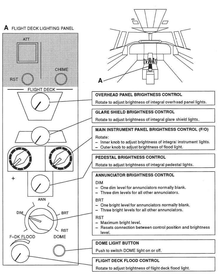
29 Flight deck lighting Flight deck lighting systems, which are controlled from the FLIGHT DECK lighting panel at the pedestal, include dome, flight deck flood, panel, instrument, and annunciator lights. Chart holder, reading, and side panel lights are also installed. A dome light for general flight deck illumination is located aft of the overhead panel. Flight deck flood lighting is provided to illuminate all flight deck panels, and can be controlled between off and fully bright. The floodlight is integrated in the dome light assembly, but control is independent of dome light switching. Overhead panel, glare shield, pedestal, and the instruments at the main instrument panel are provided with integral lighting. The main instrument panel is illuminated by a dimmable floodlight. Each panel can be controlled independently. Annunciator light brightness is controlled by one dim/bright selector. Those lights, which are normally blank, have two brightness levels: dim and bright. See also INTEGRATED ALERTING SYSTEM. All other lights have six brightness levels: three dim and three bright. The maximum brightness level is the reset position (RST). When electrical power is applied to the aircraft, the lights illuminate fully bright, irrespective of selector position. RST resets the selector for brightness control. NOTE: A STORM pushbutton, located on the LIGHTS panel, is provided to override the individual controls. When depressed, flight deck flood, main instrument panel flood, and the lighted annunciator lights, will illuminate fully bright. Two chart holder lights, one at each control wheel, can be controlled individually by a knob on top of each chart holder. Three reading lights, which are installed next to the overhead panel, provide captain, first officer, and observer with local illumination. The lights have integrated controls. Each side panel light is controlled by a selector located at the side panel.
30 Emergency and stand-by lights Emergency lights An emergency lights selector, with OFF, ARMED, and ON positions, is located on the overhead panel. Emergency lights, powered by emergency battery packs, are installed in the flight deck, toilet compartment, passenger compartment; exit signs, floor proximity escape path markings, and externally near the exits. Automatic activation occurs if AC power is not available and the emergency lights selector is in the armed position. The emergency lights can be switched on manually at the flight deck via the emergency-lights selector on the overhead panel, or via the guarded emergencylights switch at the attendant s panel. Standby lights Standby lights are installed in the toilet compartment, exit signs, and the passenger compartment. As soon as DC power is available the standby lights in the toilet compartment and the exit signs illuminate. The standby lights in the passenger compartment illuminate automatically, when DC power is available and AC power is not available.
31 Controls and indicators NOTE FOR TYPE III: The LOGO light switch is changed into BEACON light switch, which operates the lower anti-collision light.
32
33
34
35 SYSTEM OPERATION Passenger door Operation to open door From outside: Lift door handle at PUSH. Turn handle to OPEN and stand clear. The down movement can be interrupted by pushing and holding the STOP button. After release of the STOP button the down movement will be resumed at a slower speed. NOTE: If door fails to open: push door outwards. Operation to close door Push UP button and hold until door is closed. Turn handle to LOCK. If it is required to interrupt the up movement and open the door again, release the UP button and push the DOWN button. The resulting down movement can again be interrupted by pushing and holding the STOP button. After release of the STOP button the down movement will be resumed. Do not push the UP button before the down movement has been completed. CAUTION: Be aware of possible unpredicted door movements in case of door operation in strong wind conditions. Other doors Operation to open doors From outside: Lift handle at PUSH. Turn handle to OPEN. Pull door out. Form inside: Turn handle to OPEN. Push door outward. Operation to close doors Pull retract handle to unlock door. Pull door to close. Turn handle to LOCK. CAUTION: Be aware of possible unpredicted door movements in case of door operation in strong wind conditions.
36
DASSAULT AVIATION Proprietary Data
 F2000EX EASY 02-33-00 CODDE 1 PAGE 1 / 2 TABLE OF CONTENTS 02-33 02-33-00 TABLE OF CONTENTS 02-33-05 GENERAL Introduction Sources 02-33-10 DESCRIPTION General Cockpit lights Cabin lights Servicing lights
Fokker 50 - Landing Gear & Flaps
 FLIGHT CONTROLS The flight controls can be operated manually and automatically. From the flight deck, all control surfaces are mechanically operated via rod-and-cable systems, except the electrically operated
Fokker 50 - Landing Gear
 LANDING GEAR OPERATION Features General The Landing Gear (LG) consists of a forward retracting nose gear and two rearward retracting main gears. Doors enclose the landing gear bays. The LG is retracted
CHAPTER 1 AIRCRAFT GENERAL
 CHAPTER 1 AIRCRAFT GENERAL INTRODUCTION This manual provides a description of the major airframe and engine systems in the Cessna Citation Mustang (Figure 1-1). This material does not supersede, nor is
Vr V STANDARD EQUIPMENT LIST
 Vr V5.02.09 STANDARD EQUIPMENT LIST IMPORTANT NOTE: this document is a general description of the aircraft equipment only. It is not a technical document and is to be used only for the purpose of generally
TABLE OF CONTENTS. Chapter 1: AIRCRAFT - GENERAL Chapter 2: ELECTRICAL SYSTEM Chapter 3: ANNUNCIATOR SYSTEM...37
 TABLE OF CONTENTS Chapter 1: AIRCRAFT - GENERAL... 4 Chapter 2: ELECTRICAL SYSTEM...21 Chapter 3: ANNUNCIATOR SYSTEM...37 Chapter 4: FUEL SYSTEM...43 Chapter 5: ENGINE SYSTEM...60 Chapter 6: PROPELLER
P68 Observer 2 STANDARD EQUIPMENT LIST V
 P68 Observer 2 STANDARD EQUIPMENT LIST V9.03.12 P68 OBSERVER 2 IMPORTANT NOTE: this document is a general description of the aircraft equipment only. It is not a technical document and is to be used only
AW 169 Commercial in Confidence AW 169 VIP CONFIGURATION Airframe Transmission Drive System and Hydraulic System Electrical Systems
 AW 169 VIP Year of Manufacture 2017 Airframe Total Time Brand new Configuration VIP Engines PW210A Availability July 2017 LHD Warranty 3 years / 2000 hours CONFIGURATION Airframe Airframe structure including
2007 A119 Koala Price: Make an Offer
 2007 A119 Koala Price: Make an Offer Aircraft Details Manufacture Date: 2007 Hours: 87hrs Airframe: Aluminium alloy & bonded panel fuselage Semimonocoque aluminium alloy tail boom Skid type landing gear
Fokker 50 - Ice & Rain Protection. Controls and indicators of the AIRFRAME DE-ICING system are located at the ice protection panel.
 ICE AND RAIN PROTECTION AIRFRAME DE-ICING Description Controls and indicators of the AIRFRAME DE-ICING system are located at the ice protection panel. Airframe de-icing is accomplished by alternately inflating
AIRPLANE GENERAL Exterior REV 3, May 03/05
 Vol. 1 01--20--1 AIRPLANE GENERAL Exterior REV 3, May 03/05 24 ft 1 in (7.34 m) 5ft1in(1.55m) 10 ft 7 in (3.23 m) 6ft4in (1.93 m) 81 ft 6 in (24.85 m) 9ft6in(2.89m) 8ft10in (2.69 m) 36 ft 4 in (11.07 m)
CESSNA 182 CHECKLIST. LEFT WING Trailing Edge 1. Aileron CHECK freedom of movement and security
 CESSNA 182 CHECKLIST PRE-FLIGHT INSPECTION CABIN 1. Pilot s Operating Handbook AVAILABLE IN THE AIRPLANE (A.R.R.O.W.E) 2. Landing Gear Lever DOWN 3. Control Wheel Lock REMOVE 4. Ignition Switch OFF 5.
PA GURW (December 30, 2000) PRE-START. Langley Flying School. Airspeeds (MPH) for Safe Operation. Cockpit Checks
 PRE-START. Langley Flying School. Airspeeds (MPH) for Safe Operation. Cockpit Checks") Langley Flying School PA-34-200 GURW (December 30, 2000) Airspeeds (MPH) for Safe Operation V y (all weights) 105 V x (all weights) 90 En Route Climb 120 V mc 80 V yse 105 V xse 93 V r 80 V r (25 Flaps)
Langley Flying School PA-34-200 GURW (December 30, 2000) Airspeeds (MPH) for Safe Operation V y (all weights) 105 V x (all weights) 90 En Route Climb 120 V mc 80 V yse 105 V xse 93 V r 80 V r (25 Flaps)
DASSAULT AVIATION Proprietary Data
 F900EX EASY 02-30-00 CODDE 1 PAGE 1 / 2 TABLE OF CONTENTS 02-30 02-30-00 TABLE OF CONTENTS 02-30-05 GENERAL Introduction Anti-icing protection sources Anti-ice system location overview 02-30-10 DESCRIPTION
OPERATIONS MANUAL FTO SECTION : 06.04
 06.04.08. OO-WIK SECTION : 06.04 PARTENAVIA OO-WIK PAGE : 1 PRE ENTRY PITOT COVER - REMOVE SNOW / ICE CHECK AIRCRAFT NOSE INTO WIND AIRCRAFT WEIGHT & BALANCE WITHIN LIMITS EXTERNAL (COCKPIT FIRST) PARK
Cessna Citation XLS - Electrical
 GENERAL Electrical power for the Citation XLS comes primarily from DC sources originating with the starter/ generators, the Auxiliary Power Unit (APU) or the battery. A receptacle below the left engine
N123AX Piper Saratoga II HP (PA-32R-301) Checklist (v23 - Revision 3 April 2011) AIRSPEEDS FOR SAFE OPERATIONS. Best Rate of Climb (gear up, flaps up)
 Checklist (v23 - Revision 3 April 2011) AIRSPEEDS FOR SAFE OPERATIONS. Best Rate of Climb (gear up, flaps up)") N123AX Piper Saratoga II HP (PA-32R-301) Checklist (v23 - Revision 3 April 2011) AIRSPEEDS FOR SAFE OPERATIS Best Rate of Climb (gear down, flaps up) Best Rate of Climb (gear up, flaps up) Turbulent Air
N123AX Piper Saratoga II HP (PA-32R-301) Checklist (v23 - Revision 3 April 2011) AIRSPEEDS FOR SAFE OPERATIS Best Rate of Climb (gear down, flaps up) Best Rate of Climb (gear up, flaps up) Turbulent Air
DASSAULT FALCON 7X SYSTEMS SUMMARY
 DASSAULT FALCON 7X SYSTEMS SUMMARY Airframe & Doors This material is to be used for training purpose only Do not use it for flight! Please note that this document is not affiliated in any way with any
Vr (P68R) STANDARD EQUIPMENT LIST V
 STANDARD EQUIPMENT LIST V") Vr (P68R) STANDARD EQUIPMENT LIST V15.04.16 IMPORTANT NOTE: this document is a general description of the aircraft equipment only. It is not a technical document and is to be used only for the purpose
Vr (P68R) STANDARD EQUIPMENT LIST V15.04.16 IMPORTANT NOTE: this document is a general description of the aircraft equipment only. It is not a technical document and is to be used only for the purpose
SUPER KING AIR B200C Registration : PK - YGT Total Time : 9116
 CHAPTER 21 1 210101 21,010 AMM 21-10-00 L/H Flow Control Unit 101-380025-21 UNK O/C 9112 2-Oct-14 7333 0 0 0 - - - - - - 2 210106 21,050 L/H Flow Control Pneumostat 101-380013-3 UNK O/C 0 0 0 - - - - -
LAD Inc. Beechcraft King Air 200 Series Technical Ground School Syllabus Material Covered
 Topic Introduction Description Structures ATA 05 Technical Publications ATA 05 Aircraft Handling ATA 12 LAD Inc. Beechcraft King Air 200 Series Technical Ground School Syllabus Material Covered Course
PREFLIGHT CHECK COCKPIT RIGHT WING. NORMAL PROCEDURRES CHECKLIST PA-28RT 201 Arrow IV
 NORMAL PROCEDURRES CHECKLIST PA-28RT 201 Arrow IV PREFLIGHT CHECK COCKPIT Control Wheel -- Release Restraints Avionics -- OFF Parking Brake -- SET All Switches -- OFF Mixture -- IDLE CUT-OFF Master Switch
1. Aircraft General (0 Hours 39 minutes) 2. Doors (0 Hours 33 minutes) 3. EFIS (2 Hours 55 minutes) 4. Exterior Lighting (0 Hours 24 minutes)
 2. Doors (0 Hours 33 minutes) 3. EFIS (2 Hours 55 minutes) 4. Exterior Lighting (0 Hours 24 minutes)") Course: CRJ900 (Pilot) Delivery Formats: Web Based or Portable Classroom Number of modules: 26 Estimated Course Time: 36 Hours 16 minutes The following topics are included in this CRJ900 (Pilot) CBT/WBT
Course: CRJ900 (Pilot) Delivery Formats: Web Based or Portable Classroom Number of modules: 26 Estimated Course Time: 36 Hours 16 minutes The following topics are included in this CRJ900 (Pilot) CBT/WBT
ATA 36 PNEUMATIC TABLE OF CONTENTS DGT ATA 36 PNEUMATIC TABLE OF CONTENTS GENERAL Introduction Sources
 F900EX EASY 02-36-00 CODDE 1 PAGE 1 / 2 TABLE OF CONTENTS 02-36 02-36-00 TABLE OF CONTENTS 02-36-05 GENERAL Introduction Sources 02-36-10 DESCRIPTION Introduction Main sub-systems Distribution 02-36-15
B777. Electrical DO NOT USE FOR FLIGHT
 B777 Electrical DO NOT USE FOR FLIGHT 6.10 Electrical-Controls and Indicators Electrical Panel [IFE/PASS SEATS and CABIN/UTILITY switches basic with C/L 350] 1 2 IFE/PASS CABIN/ SEATS UTILITY 3 11 APU
L 298/70 Official Journal of the European Union
 L 298/70 Official Journal of the European Union 16.11.2011 MODULE 12. HELICOPTER AERODYNAMICS, STRUCTURES AND SYSTEMS 12.1 Theory of Flight Rotary Wing Aerodynamics 1 2 Terminology; Effects of gyroscopic
%#"$!!.3-2,10-* '*)+/,)(-!&(2( $"#% #"%$!&'*"()
+/,)(-!&(2( $#% #%$!&'*()") %#"$!!.3-2,10-* '*)+/,)(-!&(2( $"#% #"%$!&'*"() 0436;7328!'2?2 /1-(.!-1+% "$)0)*!&(-.),+# *#"$!>6
%#"$!!.3-2,10-* '*)+/,)(-!&(2( $"#% #"%$!&'*"() 0436;7328!'2?2 /1-(.!-1+% "$)0)*!&(-.),+# *#"$!>6
Aeroplane Aerodynamics and Flight Controls 1 2
 11.1 Theory of Flight 11.1.1. Aeroplane Aerodynamics and Flight Controls 1 2 Operation and effect of: roll control: ailerons and spoilers, pitch control: elevators, stabilators, variable incidence stabilisers
Vso 61. Vs1 63. Vr 70. Vx 76. Vxse 78. Vy 89. Vyse. 89 (blue line) Vmc. 61 (radial redline) Vsse 76. Va 134) Vno 163
 Vmc. 61 (radial redline) Vsse 76. Va 134) Vno 163") PA34-200T Piper Seneca II Normal procedures V-speeds Knots Vso 6 Vs 63 Vr 70 Vx 76 Vxse 78 Vy 89 Vyse Vmc 89 (blue line) 6 (radial redline) Vsse 76 Va 2-36(@4507lbs 34) Vno 63 Vfe 38 (0*)/2(25*)/07(40*)
PA34-200T Piper Seneca II Normal procedures V-speeds Knots Vso 6 Vs 63 Vr 70 Vx 76 Vxse 78 Vy 89 Vyse Vmc 89 (blue line) 6 (radial redline) Vsse 76 Va 2-36(@4507lbs 34) Vno 63 Vfe 38 (0*)/2(25*)/07(40*)
INDEX. Preflight Inspection Pages 2-4. Start Up.. Page 5. Take Off. Page 6. Approach to Landing. Pages 7-8. Emergency Procedures..
 INDEX Preflight Inspection Pages 2-4 Start Up.. Page 5 Take Off. Page 6 Approach to Landing. Pages 7-8 Emergency Procedures.. Page 9 Engine Failure Pages 10-13 Propeller Governor Failure Page 14 Fire.
Preflight Inspection Cabin EMPENNAGE RIGHT WING Trailing Edge RIGHT WING NOSE
 Preflight Inspection Cabin 1. Control Wheel Lock REMOVED 2. Ignition Switch OFF 3. Avionics Power Switch OFF 4. Master Switch ON 5. Fuel Quantity Indicators CHECK QUANTITY 6. Master Switch OFF 7. Fuel
OPERATIONS MANUAL SECTION 6-2
 SECTION 6-2 Index Page Pilot's Seats... 6-2-2 Pilot's Seats Adjustment... 6-2-4 Pedals Adjustment... 6-2-5 Direct Vision Windows... 6-2-6 Observer's Seat... 6-2-7 Attendant's Furnishings Typical (Version
Cessna Citation XLS - Anti-Ice & De-Ice Systems
 GENERAL The airplane utilizes a combination of engine bleed air, electrical heating elements and pneumatic boots to accomplish anti-ice/deice functions. The anti-ice system consists of bleed air heated
N1523J CHECKLIST PA Nebraska Flight Center Eppley Airfield 3737 Orville Plaza Omaha, NE Tel. (402)
") CHECKLIST N1523J 1967 Cherokee 140 PA-28-140 F Nebraska Flight Center Eppley Airfield 3737 Orville Plaza Omaha, NE 68110 Tel. (402) 342-4314 www.nebflight.com Piper Cherokee 140 N1523J 1967 GENERAL INFORMATION
CHECKLIST N1523J 1967 Cherokee 140 PA-28-140 F Nebraska Flight Center Eppley Airfield 3737 Orville Plaza Omaha, NE 68110 Tel. (402) 342-4314 www.nebflight.com Piper Cherokee 140 N1523J 1967 GENERAL INFORMATION
King Air B90. Speeds (KIAS)
") King Air B90 Speeds (KIAS) V MCA 92 V SSE (101) Derived from C90 V X 101 V Y 114 Down to 103 @ 30 000 V XSE 101 V YSE 110 Down to 101 @ 24 000 V A 169 V R 92 V 1 101 V MO 208 V FE 174 35% 130 100% V LE
King Air B90 Speeds (KIAS) V MCA 92 V SSE (101) Derived from C90 V X 101 V Y 114 Down to 103 @ 30 000 V XSE 101 V YSE 110 Down to 101 @ 24 000 V A 169 V R 92 V 1 101 V MO 208 V FE 174 35% 130 100% V LE
12.1 Theory of Flight Rotary Wing Aerodynamics 1 2
 12.1 Theory of Flight Rotary Wing Aerodynamics 1 2 Terminology; Effects of gyroscopic precession; Torque reaction and directional control; Dissymmetry of lift, Blade tip stall; Translating tendency and
V - Speeds. RV-10 V fe Flaps Speeds Trail (0 deg) Half (15 deg) Full (30 deg) 122 kias 96 kias. 80 kias
 Half (15 deg) Full (30 deg) 122 kias 96 kias. 80 kias") RV-10 Check List V - Speeds RV-10 V fe Flaps Speeds Trail (0 deg) Half (15 deg) Full (30 deg) 122 kias 96 kias 87 kias V s1 Stall (Flap Up) 60 kias V s0 Stall (Flap 40 deg) 55 kias Best Glide 80 kias V
RV-10 Check List V - Speeds RV-10 V fe Flaps Speeds Trail (0 deg) Half (15 deg) Full (30 deg) 122 kias 96 kias 87 kias V s1 Stall (Flap Up) 60 kias V s0 Stall (Flap 40 deg) 55 kias Best Glide 80 kias V
Jump to Table of Contents
 Jump to Table of Contents PIPER AIRCRAFT CORPORATION PA-28R-201, CHEROKEE ARROW III SECTION 3 EMERGENCY PROCEDURES 3.3 EMERGENCY PROCEDURES CHECK LIST ENGINE FIRE DURING
2011 DAHER-SOCATA TBM850 S/N569 D-FRAS Garmin 1000 Avionics / MT 5-blade propeller
 2011 DAHER-SOCATA TBM850 S/N569 D-FRAS Garmin 1000 Avionics / MT 5-blade propeller If you want to stay in your comfort zone, but while cruising at 31,000 feet and with an approach speed slow enough to
NORMAL CHECKLIST ATTENTION!
 Avion Training CHECKLIST Normal Checklist CESSNA 172R / TC-STS Cessna 172 R TC-STS NORMAL CHECKLIST ATTENTION! DO NOT STOW THIS CHECKLIST IN DIRECT SUNLIGHT Avion Training - Doc.nr. 212 Revision 1 / 02022018
LANCAIR LEGACY PRE-TEST FLIGHT INSPECTION (8-04)
") LANCAIR LEGACY PRE-TEST FLIGHT INSPECTION (8-04) OWNER PHONE # ADDRESS N SERIAL # AIRCRAFT TYPE DATE / / TACH TIME hrs. TOTAL TIME hrs. EMPTY WEIGHT CG. PAINT & INTERIOR? YES NO ENGINE TYPE PROPELLER ALL
LANCAIR LEGACY PRE-TEST FLIGHT INSPECTION (8-04) OWNER PHONE # ADDRESS N SERIAL # AIRCRAFT TYPE DATE / / TACH TIME hrs. TOTAL TIME hrs. EMPTY WEIGHT CG. PAINT & INTERIOR? YES NO ENGINE TYPE PROPELLER ALL
/200/300/400/500 SERIES FLAMMABLE MATERIAL LOCATIONS
 73737-100/200/300/400/500 SERIES FLAMMABLE MATERIAL LOCATIONS (tab) 1 390/492/984 GAL - 1476/1862/3725 L WINGLETS OPTIONAL AUXILIARY FUEL TANK IN LWR AFT CARGO COMPARTMENT VENT SURGE TANK FUEL TANK No.
DASSAULT AVIATION Proprietary Data
 F2000EX EASY 02-49-00 CODDE 1 PAGE 1 / 2 TABLE OF CONTENTS 02-49 02-49-00 TABLE OF CONTENTS 02-49-05 GENERAL Introduction Sources Equipment location 02-49-10 DESCRIPTION Introduction Description Operating
General Information. Sikorsky Executive S-76C+ Helicopter Serial Number January 2010
 Sikorsky Executive S-76C+ Helicopter Serial Number 760479 January 2010 Sikorsky Aircraft Corporation 6900 Main Street, P.O. Box 9729 Stratford, CT 06615-9129 (203) 386-4000 Sikorsky Aircraft Corporation
INDEX: Normal Procedures Emergency Procedures Pre Flight Inspection NORMAL PROCEDURES BEFORE STARTING ENGINE
 INDEX: Normal Procedures Emergency Procedures Pre Flight Inspection NORMAL PROCEDURES BEFORE STARTING ENGINE 1. Preflight Inspection -- COMPLETE 2. Seats, Belts, Shoulder Harnesses -- ADJUST and LOCK 3.
PA ARCHER II Quick Reference Handbook
 PA28-180 ARCHER II Quick Reference Handbook ALL GREY SHADED AREAS ARE MEMORY ITEMS 7813.03.0116 1 Table of Contents Normal Procedures... 4 PREFLIGHT CHECK... 4 BEFORE START... 6 FLOODED ENGINE START...
B737 NG Anti Ice & Rain
 B737 NG Anti Ice & Rain Introduction Thermal anti-icing (TAI), electrical anti-icing, and windshield wipers are the systems provided for ice and rain protection. The anti-ice and rain systems include:
1998 Sikorsky S76C+ Specifications and Summary
 Specifications and Summary Sikorsky S-76C+ VVIP Helicopter Page 1 of 8 Aircraft Data Manufacturer: Sikorsky Aircraft Corporation, United Technologies Model Designation: S-76C+ Serial Number: 760492 Date
Dash8 - Q400 - Pneumatics
 12.19.1 Introduction The Auxiliary Power Unit (APU) replaces the standard composite tailcone with a titanium tailcone and firewall. The APU is accessed by two clamshell type doors on the bottom of the
SURVEILLANCE CHECK LIST RENEWAL OF CERTIFICATE OF AIRWORTHINESS S/N ITEMS OF INSPECTION REMARKS SIGNATURE AIRCRAFT RELATED DOCUMENTS
 Registration No.: Type of Aircraft: Type of Engine fitted: No. of Engine: Type of Propeller (if applicable): Name of owner/ operator: C of A valid till: Place of Inspection: Name & Designation of Officer:
CARENADO COPYRIGHTS. Normal & Emergency Checklist
 NORMAL PROCEDURES CHECKLIST PREFLIGHT CHECK Control wheel -- RELEASE BELTS Avionics -- OFF Master Switch -- ON Fuel quantity gauges -- CHECK Master switch -- OFF Ignition -- OFF Exterior -- CHECK FOR DAMAGE
Interior Pre Flight Documents: Check Control Wheel Lock: Remove Flight Controls: Check Instruments: Check for Damage Switches: Verify All Off Master
 Interior Pre Flight Documents: Check Control Wheel Lock: Remove Flight Controls: Check Instruments: Check for Damage Switches: Verify All Off Master Switch ALT/BAT: On Fuel Gauge: Check Quantity Flaps:
Embraer Systems Summary [Landing Gear & Brakes]
![Embraer Systems Summary [Landing Gear & Brakes]](/thumbs/87/96901154.jpg "Embraer Systems Summary [Landing Gear & Brakes]") GENERAL DESCRIPTION The airplane has two main landing gears and a single nose gear. Each main gear is a conventional two-wheeled landing gear. The nose gear is a conventional steerable two-wheeled unit.
GENERAL DESCRIPTION The airplane has two main landing gears and a single nose gear. Each main gear is a conventional two-wheeled landing gear. The nose gear is a conventional steerable two-wheeled unit.
PA32-RT LANCE II CHECKLIST
 PA32-RT LANCE II CHECKLIST 6815.10.1112 1 Normal Procedures PREFLIGHT CHECK Control Wheel... RELEASE BELTS Parking brake... Set Master Switch... ON Fuel Quantity Gauges... check Master Switch... OFF Ignition...
Cessna 550/551/560 (PWC JT15D) Initial Aircraft Type Training Course MAINTENANCE INITIAL
 Initial Aircraft Type Training Course MAINTENANCE INITIAL") Cessna 550/551/560 (PWC JT15D) Initial Aircraft Type Training Course CONTENTS INTRODUCTION 5 COURSE DESCRIPTION 6 COURSE OBJECTIVES 7 COURSE MATERIAL 8 TIMETABLE WEEK ONE 9 TIMETABLE WEEK TWO 10 LEVEL
Cessna 550/551/560 (PWC JT15D) Initial Aircraft Type Training Course CONTENTS INTRODUCTION 5 COURSE DESCRIPTION 6 COURSE OBJECTIVES 7 COURSE MATERIAL 8 TIMETABLE WEEK ONE 9 TIMETABLE WEEK TWO 10 LEVEL
V1.0 EQUIPMENT AND PRICE LIST (V )
") V1.0 EQUIPMENT AND PRICE LIST (V7.10.18) IMPORTANT NOTE: this document is a general description of the aircraft equipment only. It is not a technical document and is to be used only for the purpose of
V1.0 EQUIPMENT AND PRICE LIST (V7.10.18) IMPORTANT NOTE: this document is a general description of the aircraft equipment only. It is not a technical document and is to be used only for the purpose of
Airworthiness Physical Survey Report
 M.A Subpart G Approval No: Airworthiness Physical Survey Report UK.MG.0035 Aircraft Type: Registration: MSN: Hours at Survey: Survey Date: Location: Audit Ref: Cycles at Survey: Documentation Review (M.A.710(c)
Cessna 172 Skyhawk. Aircraft Checklist Models: R & S
 Cessna 172 Skyhawk Aircraft Checklist Models: R & S This is an abbreviated checklist. Most explanatory items, notes cautions and warnings have been omitted for brevity. Procedures in red/bold text in this
PA28R ARROW CHECKLIST
 PA28R ARROW CHECKLIST 2300.11.0112 1 Normal Procedures Initial PREFLIGHT CHECK General Appearance... CHECKED Position & Taxi Path... CHECKED Tie Downs, Locks, Chocks & Covers... REMOVED Cockpit Controls...UNLOCKED
Preflight Inspection. Table of Contents. Left Main Landing Gear... 2A-15 Left Fuselage... 2A-16. Left Wing Trailing Edge... 2A-13
 Preflight Inspection Table of Contents Preflight Inspection Walkaround Path........ 2A-2 Exterior Walkaround Inspection............ 2A-2 Left Forward Fuselage.................. 2A-2 Nose............................
POWER ON CHECK LIST COCKPIT PREPARATION
 Normal Check List DASH 8-402 1 POWER ON CHECK LIST CIRCUIT BREAKERS... CHECKED BATTERY MASTER... ON BATTERIES... ON MAIN BUS TIE... TIED EXTERNAL POWER... AS REQUIRED APU... AS REQUIRED BATTERIES & BATTERY
NORMAL PROCEDURRES CHECKLIST PA T SENECA II PREFLIGHT CHECK INSIDE CABIN OUTSIDE CABIN
 NORMAL PROCEDURRES CHECKLIST PA-34-200T SENECA II PREFLIGHT CHECK INSIDE CABIN Avionics Master Switch -- OFF Landing Gear Control. -- DOWN Mixture Controls -- IDLE/CUTOFF Ignition Switches -- OFF Master
2009 Agusta A109S Grand Serial Number: 22126
 Serial Number: 22126 AIRFRAME Airframe Total Time: 1,018 hours Notes: Flawless machine, Only One Owner Since New! Meticulously Maintained and Operated - Always Hangared. ENGINES Pratt & Whitney 207C AVIONICS
Piper Archer II (PA )
") 1. Oil... 6-8 qts, Cap Secure CABIN 1. POH & Documents.. Check Available 2. Magneto Switch...... OFF 3. Pitot/Static Drains... Push to Drain 4. Avionics/Electrical Switches... OFF 5. Master Switch. ON
1. Oil... 6-8 qts, Cap Secure CABIN 1. POH & Documents.. Check Available 2. Magneto Switch...... OFF 3. Pitot/Static Drains... Push to Drain 4. Avionics/Electrical Switches... OFF 5. Master Switch. ON
Surface and Brakes Anti-Ice Systems
 Surface and Brakes Anti-Ice Systems WING DEICE DISTRIBUTOR VALVE TAIL DEICE R BLEED FAIL VDC FROM RIGHT ENGINE P3 PNEUMATIC AIR SHUTOFF VALVE N.O. R BK DEICE ON Ice and Rain Protection N.C. TO DOOR SEAL
OVERHEAD PANEL PROCEDURES FLASH CARDS
 OVERHEAD PANEL PROCEDURES FLASH CARDS Boeing 737-800 A supplement to the procedures and checklists publication, Flying the Boeing 737-800 NG Greg Whiley Aussie Star Flight Simulation ELECTRICAL POWER UP
CESSNA SECTION 4. Unless otherwise noted, the following speeds are based on a maximum weight of 2550 pounds and may be used for any lesser weight.
 CESSNA SECTION 4 INTRODUCTION Section 4 provides procedures and amplified instructions for normal operations using standard equipment. Normal procedures associated with optional systems can be found in
Cessna 172P PPL Checklist Page 1
 Cessna 172P PPL Checklist 06-08-2017 Page 1 Cessna 172P PPL Checklist 06-08-2017 Page 2 Checklist Items Informational Items Critical Memory Items PREFLIGHT COCKPIT CHECK (DO-LIST) Pitot Cover -- REMOVE
Diamond DA40 TDI OH-STL
 Diamond DA40 TDI OH-STL NORMAL, EMERGENCY AND ABNORMAL CHECKLISTS PREFLIGHT INTERIOR + EXTERIOR. 1 Check Aircraft papers 2 Remove pitot cover 3 Check interior for foreign objects 4 Check flight controls
PA , Model E Normal Checklist (04/15/11)
") PA-23-250, Model E Normal Checklist (04/15/11) Key Airspeeds IAS-MPH V NE 249 V NO 198 V LO/LE 150 V A (At max gross weight.) 149 Speed for single engine cruise. 138 V FE Quarter Flaps 160 Half Flaps 140
PA-23-250, Model E Normal Checklist (04/15/11) Key Airspeeds IAS-MPH V NE 249 V NO 198 V LO/LE 150 V A (At max gross weight.) 149 Speed for single engine cruise. 138 V FE Quarter Flaps 160 Half Flaps 140
Official Journal of the European Union L 298/53
 16.11.2011 Official Journal of the European Union L 298/53 A B1 B2 B3 10.6 Continuing airworthiness 2 2 2 2 Detailed understanding of Part-21 provisions related to continuing airworthiness. Detailed understanding
HU-16 Albatross USER MANUAL. Virtavia HU-16 Albatross DTG Steam Edition Manual Version 1.0
 HU-16 Albatross USER MANUAL 0 Introduction The Grumman HU-16 Albatross is a twin-engine amphibious flying boat. First flown in 1949, the HU-16 underwent a number of modifications and improvements over
INTRODUCTION. This Catalog:
 Editor s Note: This Parts Catalog has been reproduced from the original Republic Parts Catalog. Obviously, most of the information is obsolete; the pictures are accurate and up-to-date. If nothing else,
Section 5 - Ice & Rain Protection
 Section 5-5.1 Ice Detection 5.2 Ice Protection 5.2 Control 5.2 Operation 5.3 Engine Inlet 5.3 Pitot 5.4 Operation 5.4 Stall Warning Vane 5.4 Operation 5.4 Windshield 5.5 Windshield Anti-Ice Diagram - High
CHAPTER 14 LANDING GEAR
 CHAPTER 14 LANDING GEAR Page TABLE OF CONTENTS 14-00-01/02 DESCRIPTION General 14-10-01 Description 14-10-01 Controls and Indicators 14-10-04 COMPONENTS Nose Gear 14-20-01 Main and Center Gear 14-20-02
PREFLIGHT CHECKLIST PA28R-200
 PREFLIGHT CHECKLIST PA28R-200 COCKPIT AND CABIN MAINTENANCE STATUS VERIFIED / CLEARED HOBBS / TACH METERS VERIFIED / RECORDED POH / AIRCRAFT DOCUMENTS AVAILABLE / PARKING BRAKE SET FLIGHT CONTROLS FREE
DOORS Table of Contents REV 3, May 03/05 CHAPTER DOORS. INTRODUCTION Introduction System Circuit Breakers
 Vol. 1 06--00--1 DOOR Table of Contents REV 3, May 03/05 CHAPTER 6 --- DOOR Page TABLE OF CONTENT 06-00 -1 Table of Contents 06--00--1 INTRODUCTION 06-10 -1 Introduction 06--10--1 ystem Circuit Breakers
PA WARRIOR II Quick Reference Handbook
 PA28-161 WARRIOR II Quick Reference Handbook Version 1.0 ALL GREY SHADED AREAS ARE MEMORY ITEMS Normal Procedures Pre-Flight Check... N-1 Before Start... N-3 Flooded Engine Start... N-4 Starting With
PAC 750XL PAC 750XL PAC-750XL
 PAC 750XL The PAC 750XL combines a short take off and landing performance with a large load carrying capability. The PAC 750XL is a distinctive type. Its design philosophy is reflected in the aircraft's
Aircraft Checklist Commander 114
 Aircraft Checklist Commander 114 This is an abbreviated checklist. Most explanatory items, notes cautions and warnings have been omitted for brevity. Procedures in red/bold text in this checklist should
Aircraft Design: A Systems Engineering Approach, M. Sadraey, Wiley, 2012 Chapter 11 Aircraft Weight Distribution Tables
 Aircraft Design: A Systems Engineering Approach, M. Sadraey, Wiley, 01 Chapter 11 Aircraft Weight Distribution Tables No Component group Elements Weight X cg Y cg Z cg 1 Wing 1.1. Wing main structure 1..
Dash8-200/300 - Airplane General GENERAL AIRCRAFT GENERAL. Page 1. Outside dimensions m 7.92 m m m *
 GENERAL AIRCRAFT GENERAL Outside dimensions 3.96 m 27.4 m 7.92 m 3.65 m * 7.87 m 0.94 m * CLEARANCE (STATIC) 1.18 m 2.54 m 2.03 m 1.50 m 25.70 m 7.50 m * 3.20 m * 10.00 m Page 1 Communication and navigation
MODEL 95 PARTS CATALOG ALPHABETICAL INDEX , 21, 21A 31 3, 4, 4A , 58A 60 61A, 61B, 61C
 A MODEL 5 PARTS CATALOG FIGURE A FIGURE Access Doors, Wing Accessories 7 Accumulatn~.' Propeller Governor Unfeathering. 56 Actuator Aileron T"JJ. Cover, Fl2v Cowl Flap Elevator Tab. Flap. Landing Gear
Convair XB-46 USER MANUAL. Virtavia XB-46 Manual Version DTG 1.0
 Convair XB-46 USER MANUAL 0 Introduction For the 1944 jet bomber competition, Consolidate Vultee (which became Convair) offered their model 109, which featured four Allison J-35-C-3 jet engines slung under
Cessna 182S-CHECKLIST PROCEDURES
 Cessna 182S-CHECKLIST PROCEDURES PREFLIGHT INSPECTION 1 CABIN 1. Pitot Tube Cover -- REMOVE (if installed) and check for stoppage 2. Pilot s Operating Handbook AVAILABLE IN THE AIRPLANE 3. Airplane Weight
Fokker 50 - Limitations GENERAL LIMITATIONS MASS LIMITATIONS. Page 1. Minimum crew. Maximum number of passenger seats.
 GENERAL LIMITATIONS Minimum crew Cockpit: Two pilots Maximum number of passenger seats Sixty-two (62) Maximum operating altitudes Maximum operating pressure altitude: Maximum take-off and landing pressure
David s Flight Simulator Operations Manual
 DPW Solutions David s Flight Simulator Operations Manual Draft 0.2 David Woolterton Update 10/5/2016 Table of Contents Pre-Start Checklist... 2 Startup Checklist... 3 Before Taxi Checklist... 3 Taxi Checklist...
HELICOPTERS. Technical Data
 HELICOPTERS Technical Data 2017 EC145 2.7 External Sound Levels Flight Phase Measurements according ICAO Annex 16 ICAO limits at 3,585 kg Measurements according FAR Part 36 FAR 36 limits at 3,585 kg Takeoff
AIRSPEEDS. Cessna 172R Emergency Checklist
 AIRSPEEDS AIRSPEEDS FOR EMERGENCY OPERATION Cessna 172R Emergency Checklist INTRODUCTION This document provides checklist and amplified procedures for coping with emergencies that may occur. Emergencies
King Air 200. Self-Check Exercises. cae.com. Revision 0
 King Air 200 Self-Check Exercises Revision 0 cae.com Copyright 2011, CAE, Inc. All rights reserved Printed in the United States of America Orientation Welcome to CAE Use of these Self- Check Exercises
DASSAULT AVIATION Proprietary Data
 02-25-05 ATA 25 EQUIPMENT CODDE 1 PAGE 1 / 2 GENERAL ACRONYMS AC CB CCD CVR DC DFDR ELT SSPC Alternative Current electricity Circuit Breaker Cursor Control Device Cockpit Voice Recorder Direct Current
A. Stall Warning System - Serials w/o Ice Protection
 Stall Warning System GENERAL 27-31: STALL WARNING SYSTEM 1. General A. Stall Warning System - Serials w/o Ice Protection The airplane uses an electro-pneumatic stall warning system. As the angle of attack
CHECKLIST 1969 CESSNA 172-K. NOTE: Verify all information with airplane's POH
 CHECKLIST 1969 CESSNA 172-K NOTE: Verify all information with airplane's POH PRE-FLIGHT INSPECTION 1 CABIN 1 A.R.R.O.W. CHECK Airworthiness Cert. In Clear View Registration In Clear View Radio License
SECTION 2-05 ELECTRICAL
 SECTION 2-05 TABLE OF CONTENTS Block General...2-05-05...01 DC System...2-05-05...02 DC System Protection...2-05-05...04 External Power Source...2-05-05...05 Batteries...2-05-05...06 Backup Battery...2-05-05...07
The engines are designed to use 100/130 octane fuel. If not available use next higher grade. - 1
 PNEUMATIC SYSTEM The aircraft has a dual pneumatic system. In case of failure of either pneumatic pump, the system will automatically select the operative source. (Inoperative source will be indicated
Aircraft Checklist Cessna 182T
 Aircraft Checklist Cessna 182T This is an abbreviated checklist. Most explanatory items, notes cautions and warnings have been omitted for brevity. Procedures in red/bold in this checklist should be committed
ATR72 DGCANO SUBJECT REFERENCE COMPLIANCE APPLICABILITY
 DGCA/ATR 72/1 DGCA/ATR 72/2 TO ENSURE THAT FLIGHT CREWS ACTIVATE THE WING & TAIL PNEUMATIC DEICING BOOTS TO PREVENT FATIGUE CRACKING OF THE FUSELAGE & THE PAX. & SERVICE DOORS FAA AD 99-19-10 FAA AD 2000-04-13
MAJESTIC Q400 SHARED COCKPIT FLOWS CHECKLISTS MULTIPLAYER OPERATIONS.
 PRE LOAD IN Agree on Ports, Share IP and select who will be doing W&B. INITIAL LOAD IN On 1 System transfer Weight and Balance to Simulator Pause Simulation Save Flight as normal FSX Flight Transfer Save
STALL WARNING SYSTEM 1. DESCRIPTION A.
 STALL WARNING SYSTEM 1. DESCRIPTION A. Stall Warning System - Serials w/o Perspective Avionics The airplane uses an electro-pneumatic stall warning system. As the angle of attack increases and the airplane
SECTION 2 LIMITATIONS
 SECTION 2 TABLE OF CONTENTS PARAGRAPH PAGE 2.1 INTRODUCTION 2-1 2.2 KINDS OF OPERATIONS LIMITS 2-1 2.3 AIRSPEED 2-3 2.4 AIRSPEED INDICATOR MARKINGS 2-3 2.5 POWER PLANT 2-4 2.6 POWER PLANT INSTRUMENT MARKINGS