2013 X0 Trail Service Manual
|
|
|
- Tabitha McDaniel
- 6 years ago
- Views:
Transcription

1 2013 X0 Trail Service Manual GEN Rev A 2012 SRAM LLC
2 SRAM LLC WARRANTY Extent of Limited Warranty Except as otherwise set forth herein, SRAM warrants its products to be free from defects in materials or workmanship for a period of two years after original purchase. This warranty only applies to the original owner and is not transferable. Claims under this warranty must be made through the retailer where the bicycle or the SRAM component was purchased. Original proof of purchase is required. Except as described herein, SRAM makes no other warranties, guaranties, or representations of any type (express or implied), and all warranties (including any implied warranties of reasonable care, merchantibility, or fitness for a particular purpose) are hereby disclaimed. Local law This warranty statement gives the customer specific legal rights. The customer may also have other rights which vary from state to state (USA), from province to province (Canada), and from country to country elsewhere in the world. To the extent that this warranty statement is inconsistent with the local law, this warranty shall be deemed modified to be consistent with such law, under such local law, certain disclaimers and limitations of this warranty statement may apply to the customer. For example, some states in the United States of America, as well as some governments outside of the United States (including provinces in Canada) may: a. Preclude the disclaimers and limitations of this warranty statement from limiting the statutory rights of the consumer (e.g. United Kingdom). b. Otherwise restrict the ability of a manufacturer to enforce such disclaimers or limitations. For Australian customers: This SRAM limited warranty is provided in Australia by SRAM LLC, 133 North Kingsbury, 4th floor, Chicago, Illinois, 60642, USA. To make a warranty claim please contact the retailer from whom you purchased this SRAM product. Alternatively, you may make a claim by contacting SRAM Australia, 6 Marco Court, Rowville 3178, Australia. For valid claims SRAM will, at its option, either repair or replace your SRAM product. Any expenses incurred in making the warranty claim are your responsibility. The benefits given by this warranty are additional to other rights and remedies that you may have under laws relating to our products. Our goods come with guarantees that cannot be excluded under the Australian Consumer Law. You are entitled to a replacement or refund for a major failure and for compensation for any other reasonably foreseeable loss or damage. You are also entitled to have the goods repaired or replaced if the goods fail to be of acceptable quality and the failure does not amount to a major failure. Limitations of Liability To the extent allowed by local law, except for the obligations specifically set forth in this warranty statement, in no event shall SRAM or its third party suppliers be liable for direct, indirect, special, incidental, or consequential damages. Limitations of Warranty This warranty does not apply to products that have been incorrectly installed and/or adjusted according to the respective SRAM user manual. The SRAM user manuals can be found online at sram.com, rockshox.com, avidbike.com, truvativ.com, or zipp.com. This warranty does not apply to damage to the product caused by a crash, impact, abuse of the product, non-compliance with manufacturers specifications of usage or any other circumstances in which the product has been subjected to forces or loads beyond its design. This warranty does not apply when the product has been modified, including, but not limited to any attempt to open or repair any electronic and electronic related components, including the motor, controller, battery packs, wiring harnesses, switches, and chargers. This warranty does not apply when the serial number or production code has been deliberately altered, defaced or removed. This warranty does not apply to normal wear and tear. Wear and tear parts are subject to damage as a result of normal use, failure to service according to SRAM recommendations and/or riding or installation in conditions or applications other than recommended. Wear and tear parts are identified as: Dust seals Bushings Air sealing o-rings Glide rings Rubber moving parts Foam rings Rear shock mounting hardware and main seals Upper tubes (stanchions) Stripped threads/bolts (aluminium, titanium, magnesium or steel) Brake sleeves Brake pads Chains Sprockets Cassettes Shifter and brake cables (inner and outer) Handlebar grips Shifter grips Jockey wheels Disc brake rotors Wheel braking surfaces Bottomout pads Bearings Bearing races Pawls Transmission gears Spokes Free hubs Aero bar pads Corrosion Tools Motors Batteries Notwithstanding anything else set forth herein, this warranty is limited to one year for all electronic and electronic related components including motors, controllers, battery packs, wiring harnesses, switches, and chargers. The battery pack and charger warranty does not include damage from power surges, use of improper charger, improper maintenance, or such other misuse. This warranty shall not cover damages caused by the use of parts of different manufacturers. This warranty shall not cover damages caused by the use of parts that are not compatible, suitable and/or authorised by SRAM for use with SRAM components. This warranty shall not cover damages resulting from commercial (rental) use. 2
3 Table of Contents brake service overview... 5 lever overhaul... 6 lever exploded view... 6 Parts and tools needed for service... 6 caliper overhaul caliper exploded view...14 Parts and tools needed for service...14 troubleshooting...15 hose length adjustment...21 Parts and tools needed for service...21 brake bleed procedure...25 Parts and tools needed for service:...25 PAD replacement INSTRUCTIONS...31 disc brake pad and rotor bed-in procedure
4 SAFETY FIRST! At SRAM, we care about YOU. Please, always wear your safety glasses and protective gloves when servicing your products. Protect yourself! Wear your safety gear!
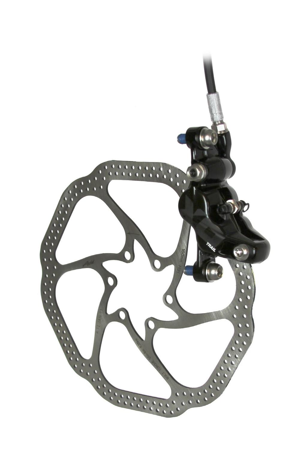
5 safety instructions Always wear safety glasses and nitrile gloves when working with DOT fluid. Place an oil pan on the floor underneath the area where you will be working on the brake. Used DOT fluid should be recycled or disposed of in accordance to local and federal regulations. Never pour DOT fluid down a sewage or drainage system or into the ground or a body of water. DOT fluids will damage painted surfaces. If any fluid comes in contact with a painted surface (i.e. your frame) or printing on the brakes, wipe it off immediately and clean with isopropyl alcohol or water. Removal of paint and/or printing by DOT fluid is not covered under warranty. Do not allow any brake fluid to come in contact with the brake pads. If this occurs, the pads are contaminated and must be replaced. For best results, use only Avid High-Performance 5.1 DOT Fluid. If Avid fluid is not available, only use DOT 5.1 or 4 fluid. Do not use mineral oil or DOT 5 fluid. brake service overview Avid brake systems need to be serviced periodically to optimize braking function. If brake fluid is leaking from any area of the brake, there may be damage or wear and tear to the internal moving parts. If the system has been contaminated with the wrong fluid, there may be damage to all rubber and plastic internal parts. If your brake was damaged in a crash, there may be damage to the lever blade, pushrod, and housing assemblies. Inspect and replace these parts to restore proper brake function. Your product's appearance may differ from the pictures contained in this publication. 5 brake service overview


 T10,")
6 lever overhaul lever exploded view a b c d e f g h i Tooled reach adjust models a. hose stop f. Lever blade B. pivot bolts g. Contact adjuster C. piston spring H. Lever return spring d. Piston/bladder/pushrod assembly i. Reach adjuster e. Snap ring Parts and tools needed for service Safety glasses Long tipped snap ring pliers Nitrile gloves Oil pan Isopropyl alcohol Clean, lint-free rag Avid High-Performance 5.1 DOT Fluid or DOT 4 Fluid, or Avid DOT Grease or DOT 5.1 or 4 compatible grease Bench vise Pick with a 90 degree bent tip 3 mm hex wrench (tooled reach adjust models only) T10, T25 TORX wrench T10, T25 TORX bit socket 11 mm open end wrench 8 mm flare nut wrench 8 mm flare nut crowfoot Torque wrench 6 lever overhaul


7 1 Use a T25 TORX wrench to remove the brake clamp bolt from the Discrete clamp, MMX, or XLoc (XLoc requires removal of the shifter). Remove the brake lever from the handlebar. Pull the hose boot off the compression nut and slide it down the hose. T25 Discrete Clamp 2 Use an 11 mm open end wrench to hold the hose stop in place and use an 8 mm flare nut wrench to remove the hose compression nut. Pull the brake hose and compression fitting from the brake lever body. 8 mm 11 mm 3 Pour the brake fluid into an oil pan. Squeeze the lever to pump excess brake fluid from inside the lever assembly. If the system has been contaminated with the wrong fluid, flush all the parts with soapy water, rinse, and allow to dry prior to rebuilding. Install all new seals and a new hose. 4 Use a T10 TORX to remove the pivot bolts from both sides of the lever. T10 7 lever overhaul


8 5 Use a pick to disengage the return spring eyelet from the spring anchor tab. Spring anchor tab Return spring eyelet 6 Turn the reach adjuster counter-clockwise until the adjuster disengages from the pushrod. Tooled reach adjust models: Use a 3 mm hex wrench to turn the reach adjuster. 7 Remove the lever from the lever body. 8 Clamp a 2 mm hex wrench into a bench vise, with the tool positioned vertically. Insert the lever body on the wrench through the fluid flow port in the master cylinder head. Place a clean rag under the lever body to wipe up any fluid that may spill out. 2 mm 8 lever overhaul


9 9 Use the pliers to apply downward pressure to the lever body and remove the snap ring. Remove the piston/bladder assembly. caution - eye hazard Do not look directly into the lever body while performing this step. The internal piston/spring assembly is preloaded and will come out of the lever body quickly, which can result in injury. Wear safety glasses. 10 Lubricate a new piston/bladder/snap ring assembly by dipping it into Avid High-Performance 5.1 DOT Fluid. You can also use Avid DOT Grease, or DOT 5.1 or 4 compatible grease, as a lubricant. 9 lever overhaul


10 11 Insert the piston/bladder assembly into the lever body with the keyed section of the piston retainer oriented toward the opening in the lever body. Use the snap ring pliers to push the piston/bladder assembly into the lever body, and secure the snap ring in its groove. Orient the snap ring eyelets opposite the opening in the lever body. You can also use a 10 mm deep socket against the snap ring to push the piston/bladder/snap ring assembly into the lever body. If you push the snap ring past its groove, you can use the 2 mm hex in the vise to push on the assembly from inside the fluid flow port, which will seat the snap ring into the groove. 10 lever overhaul


11 12 Insert the lever blade into the lever body. Thread the reach adjuster onto the pushrod and turn it clockwise an additional 5-6 complete turns. Tooled reach adjust models: Use a 3 mm hex wrench to turn the reach adjuster. 11 lever overhaul


12 13 Use the angled tip of a pick to lift and fasten the eyelet of the lever return spring onto the spring anchor tab on the snap ring. 14 Use a T10 TORX wrench to install the pivot bolts into both sides of the lever. Use a torque wrench with a T10 TORX bit socket to tighten the pivot bolts to N m (10-11 in-lb). T N m (10-11 in-lb) 12 lever overhaul

 16 Reinstall the brake lever to the Discrete clamp, MMX, or XLoc.")
13 15 Thread the compression nut into the lever body until it stops. Hold the hose stop secure with an 11 mm open end wrench and use a torque wrench with an 8 mm flare nut crowfoot to tighten the compression nut to N m (43-48 in-lb). Spray isopropyl alcohol on the lever and clean it with a rag. Slide the hose boot onto the compression nut. 8 mm 11 mm N m (43-48 in-lb) 16 Reinstall the brake lever to the Discrete clamp, MMX, or XLoc. Use a torque wrench with a T25 TORX bit socket to reinstall the brake clamp bolt into the Discrete clamp, MMX, or XLoc and tighten it to 5-6 N m (44-52 in-lb). T N m (44-52 in-lb) 13 lever overhaul

14 caliper overhaul caliper exploded view a b c d e f g h i J K L a. E-clip g. Banjo fitting B. Piston seals H. Inboard caliper body half C. Brake pad i. Caliper pistons d. Outboard caliper body half j. Pad spreader clip e. Caliper body bolt K. Caliper o-ring f. Pad retainer bolt L. Banjo bolt Parts and tools needed for service Safety glasses Needle nose pliers Nitrile gloves Oil pan Isopropyl alcohol Clean, lint-free rag Avid High-Performance 5.1 DOT Fluid or DOT 4 Fluid, or Avid DOT Grease or DOT 5.1 or 4 compatible grease Air compressor with rubber-tipped blow gun chuck Soft rubber mat or small section of butyl inner tube Pick with a 90 degree bent tip 2.5, 5 mm hex wrench 2.5 mm hex bit socket T25 TORX T25 TORX bit socket 8 mm open end wrench 8 mm flare nut crowfoot Torque wrench 14 caliper overhaul
15 troubleshooting Sticky or slow brake pad return feel/excessive lever throw Before completely disassembling your caliper, it s worth trying to loosen the sticky pistons. Try the following: 1. Clamp the bicycle in a bicycle work stand. 2. Remove the affected wheel. 3. Squeeze the brake lever several times until the pads nearly contact one another. 4. Push the XO Trail pad spreader clip in between the pads to spread the pads to the full width of the clip. 5. Remove the clip. 6. Repeat steps 3-5 several times. 7. Reinstall the wheel. 8. Squeeze the lever several times to position the pads at the proper distance from the rotor. 9. Center the caliper on the rotor if necessary. 10. Spin the wheel and check brake function. All pistons should now be moving freely and there should not be excessive lever throw. If there is no improvement, continue with caliper service. 15 caliper overhaul


16 1 Use a 5 mm hex wrench to remove the brake caliper from the fork or frame and remove the caliper mounting bracket and hardware from the caliper. Set aside in the correct order. 2 Remove the e-clip from the pad retainer bolt. Use a 2.5 mm hex wrench to remove the pad retainer bolt from the caliper. 2.5 mm 3 Pull on the brake pad tabs to remove the pads and pad spreader clip. If the total thickness of the backing plate and pad friction material is less than 3 mm, the brake pads need to be replaced. 4 Use an 8 mm open end wrench to remove the banjo bolt, and a T25 TORX wrench to remove the caliper body bolt. Brake fluid will leak, so hold the caliper over a container to catch the fluid. Set the hose and banjo fitting aside 8 mm T25 5 Separate the caliper body halves. 16 caliper overhaul


17 6 Caliper Piston Removal: Place one of the caliper halves, piston side down, on a soft rubber mat or a small section of inner tube on a flat surface. Insert a rubber-tipped blow gun chuck nozzle into the banjo port. While firmly pushing against the caliper half and chuck nozzle, squeeze the air chuck to force air into the banjo port and unseat the pistons from the caliper. Place a rag over the caliper to contain any fluid that may spray. Continue to force air into the caliper until both pistons unseat. Do not remove one piston if the other is still seated. Remove the pistons from the caliper. Repeat this process for the other caliper half. caution - eye hazard Forced air will dislodge the caliper pistons rapidly, which can lead to bodily injury or damage to the parts. Point the caliper pistons toward a rubber surface before forcing air into the caliper. 7 Use a pick to remove the piston seals from inside each caliper body half. Install new seals inside each caliper body half. Do not scratch the seal gland with the pick. You can also use Avid DOT Grease or DOT 5.1 or 4 compatible grease as a lubricant. 17 caliper overhaul


18 8 Inspect the caliper pistons for damage and replace them if necessary. Apply a small amount of DOT 5.1 fluid to the circumference of each piston. Reinstall the pistons into each half of the caliper body. Wipe any excess fluid from the caliper halves. There are two larger diameter pistons and two smaller diameter pistons. Install one of each into each caliper half. You can also use Avid DOT Grease or DOT 5.1 or 4 compatible grease as a lubricant. 9 Remove the banjo port o-ring from the outboard caliper half. 10 Remove the o-rings from the banjo bolt and banjo fitting. Apply a small amount of DOT 5.1 fluid to the new o-rings and install them. 18 caliper overhaul


 12 Hold the banjo fitting at the desired")
19 11 Reassemble the caliper halves. Insert the banjo bolt through the outboard caliper half. Apply a small amount of DOT 5.1 fluid to the caliper o-ring and install it onto the banjo bolt. Place the inboard caliper half onto the banjo bolt. Place the banjo fitting onto the threads of the banjo bolt. Turn the bolt into the fitting until it stops. Do not tighten the banjo bolt yet. Install the caliper body bolt and use a torque wrench with a T25 TORX bit socket to tighten it to N m ( in-lb). T N m ( in-lb) 12 Hold the banjo fitting at the desired angle. Use a torque wrench with an 8 mm flare nut crowfoot to tighten the banjo bolt to N m ( in-lb). 8 mm N m ( in-lb) 19 caliper overhaul

20 13 Insert the Bleed Block into the caliper in place of the brake pads. You will need to bleed your brakes before reinstalling the brake pads. Click here for detailed brake pad removal instructions 14 Spray isopropyl alcohol on the caliper and clean it with a rag. Visually check your work. If there are any o-rings that are protruding beyond the outside edges of the banjo or bolt, remove and replace the o-rings, then repeat the installation process. Overhauling the caliper introduces a small amount of air into the system. It is necessary to bleed the brakes for optimal performance. Click here for detailed brake bleed instructions 20 caliper overhaul
21 hose length adjustment safety instructions Always wear safety glasses and nitrile gloves when working with DOT fluid. Place an oil pan on the floor underneath the area where you will be working on the brake. Used DOT fluid should be recycled or disposed of in accordance to local and federal regulations. Never pour DOT fluid down a sewage or drainage system or into the ground or a body of water. DOT fluids will damage painted surfaces. If any fluid comes in contact with a painted surface (i.e. your frame) or printing on the brakes, wipe it off immediately and clean with isopropyl alcohol or water. Removal of paint and/or printing by DOT fluid is not covered under warranty. Do not allow any brake fluid to come in contact with the brake pads. If this occurs, the pads are contaminated and must be replaced. For best results, use only Avid High-Performance 5.1 DOT Fluid. If Avid fluid is not available, only use DOT 5.1 or 4 fluid. Do not use mineral oil or DOT 5 fluid. Parts and tools needed for service Safety glasses Hydraulic hose cutters or very sharp cable housing cutters Nitrile gloves T10 TORX Isopropyl alcohol 8 mm flare nut wrench Clean, lint-free rag 11 mm open end wrench Avid DOT Grease or DOT 5.1 or 4 compatible grease Torque wrench 1 Make sure the hoses are properly secured to the bicycle and check the routing of each hose. Account for suspension movement and be sure the handlebars can move freely by turning the bars all the way from side to side. 2 Pull the hose boot away from the lever to access the compression nut. If the boot sticks, use a zip tie to pry up a corner of the boot and spray isopropyl alcohol between the boot and the lever. Work the alcohol in; the boot should loosen up and slide easily down the hose. 21 hose length adjustment
22 3 For models with a compression nut and a hex hose stop: Use an 11 mm open end wrench to hold the hose stop in place and use an 8 mm flare nut wrench to unthread the compression nut. For models with a compression nut only: Use an 8 mm flare nut wrench to unthread the compression nut. Hex hose stop Compression nut Compression nut 4 Pull the hose from the lever. Be careful, DOT fluid will drip from the hose. Try not to spill too much fluid because any fluid that drips out will create bubbles that you ll have to eliminate later. Slide the nut down the hose and away from the end where you ll be cutting. Do not pull the brake lever while the hose is removed. 5 Determine where you need to cut the hose by holding it up to the lever in the position you like. Leave a gentle bend in the hose with enough length to freely turn the bars all the way from side to side. Double-check this measurement. The groove in the lever nose marks the spot where you ll cut the hose. Cut the hose using hydraulic hose cutters or very sharp cable housing cutters. Measure twice, cut once! 22 hose length adjustment
23 6 Apply Avid DOT Grease to the threads of a new hose barb, the compression fitting outer surfaces and compression nut threads. While holding the hose firmly, use a T10 TORX to thread the hose barb into the end of the hose until it is flush. Slide a new compression fitting over the end of the hose with the new hose barb. 7 Push the hose firmly into the lever until it stops. While holding the hose in place, slide the compression fitting and compression nut up to the lever or hose stop. 23 hose length adjustment
24 8 For models with a compression nut and a hex hose stop: While continuing to push the hose into the hose stop, use an 11 mm open end wrench to hold the hose stop in place and use an 8 mm flare nut wrench to tighten the compression nut to the proper torque. For models with a compression nut only: While continuing to push the hose into the lever body, use an 8 mm flare nut wrench to tighten the compression nut to the proper torque. If your compression fitting is alloy, tighten to 5 N m (47 in-lb). If your compression fitting is steel, tighten to 7.8 N m (70 in-lb) 9 Slide the boot back into place. After completing the hose length adjustment, bleed the brakes for optimal performance. Click here for detailed brake bleed instructions 24 hose length adjustment
25 brake bleed procedure Avid brakes are the most powerful and precise hydraulic brakes on the market. A key reason behind this is the ability to optimize brake performance with a perfect bleed. The goal of bleeding is to remove any air that is trapped in the hose, caliper, or lever. Air trapped in a hydraulic brake system degrades the performance of the brake. The following instructions will walk you through our simple bleed procedure. Avid brakes come with hoses attached and bled. If you don t need to change the hose length, you do not need to bleed the system prior to installation. Supplemental video instruction is available at safety instructions Always wear safety glasses and nitrile gloves when working with DOT fluid. Place an oil pan on the floor underneath the area where you will be working on the brake. Used DOT fluid should be recycled or disposed of in accordance to local and federal regulations. Never pour DOT fluid down a sewage or drainage system or into the ground or a body of water. DOT fluids will damage painted surfaces. If any fluid comes in contact with a painted surface (i.e. your frame) or printing on the brakes, wipe it off immediately and clean with isopropyl alcohol or water. Removal of paint and/or printing by DOT fluid is not covered under warranty. Do not allow any brake fluid to come in contact with the brake pads. If this occurs, the pads are contaminated and must be replaced. Do not re-use fluid. Do not leave the hose clamps closed, this will damage the clear tubing on the syringes. For best results, use only Avid High-Performance 5.1 DOT Fluid. If Avid fluid is not available, only use DOT 5.1 or 4 fluid. Do not use mineral oil or DOT 5 fluid. Parts and tools needed for service: Safety glasses Avid Bleed Kit or Avid Professional Bleed Kit Nitrile gloves Avid Bleed Block Isopropyl alcohol T10 TORX Clean, lint-free rag 2.5 and 4 mm hex wrenches Avid High-Performance 5.1 DOT Fluid or DOT 4 Fluid Pick Compression fittings Hose barbs TORX Syringes Avid High-Performance DOT Fluid Bleed Block (actual bleed block may differ) Avid Bleed Kit Contents 25 brake bleed procedure
26 Bleeding Avid brakes forces air bubbles out of the system. We recommend that you bleed your brakes at least once a year to ensure optimal performance. If you ride frequently or in aggressive terrain, you should bleed your brakes more often. When bleeding brakes, you may notice discoloration of the old fluid as it exits the system into the syringe at the lever. If the fluid is severely discolored, this indicates that the fluid is very old. In this case, bleeding the system twice in order to completely remove the old fluid is recommended. 1 Fill one syringe 1/2 full with Avid High-Performance 5.1 DOT Fluid and fill the other syringe 1/4 full. Hold each syringe with the tip pointed up and tap the side of the syringe with your finger to bring any air bubbles to the top. Place a clean rag around the tip and slowly push the air bubbles out of the syringe. Close the hose clamp on each syringe. 2 De-gas the fluid in the 1/2 full syringe. Leave the hose clamp shut and pull on the plunger. Bubbles will form in the brake fluid. While the plunger is still pulled down, lightly tap the syringe to release the bubbles sticking to the sides and the bottom so that they can rise to the top of the fluid. When the bubbles stop forming and have all risen to the top, release the plunger, open the clamp and carefully push the air out. Repeat several times. You will not be able to remove all the bubbles. 3 Remove the wheel from your bike. Remove the brake pads and spreader clip from the caliper and insert the appropriate Bleed Block. This will help prevent system overfill and keep DOT fluid from contaminating your brake pads. Click here for detailed brake pad removal instructions 4 Use the T10 TORX to remove the caliper bleed port screw from the caliper body or banjo bolt 5 Make sure the fluid in the 1/2 full syringe is pushed all the way to the tip so that there is no air gap, then thread into the caliper bleed port. 26 brake bleed procedure
27 6 For models with Contact Point Adjustment and a rotating bleed port screw located on the contact point adjuster: rotate the adjuster in the direction opposite the arrow until it stops, then rotate the adjuster back just enough to place the bleed screw at its highest point. For models with Contact Point Adjustment and a fixed bleed port screw: rotate the adjuster in the direction opposite the arrow on the adjuster knob until it stops. 7 For models equipped with Reach Adjust: make sure the tip of the lever blade is mm from the centerline of the handlebar. If the lever is too far out, it can make bleeding the brake impossible mm 8 Use the T10 TORX to remove the lever bleed port screw. 9 Make sure the fluid in the 1/4 full syringe is pushed all the way to the tip so that there is no air gap, then thread into the lever bleed port. It is not necessary to reposition the angle of the brake lever on the handlebar. You may have a small amount of DOT fluid drip from the bleed port screw, this is normal. Just have a clean rag handy to wipe off any excess after the syringe is installed. 27 brake bleed procedure
28 Hold both syringes upright. 10 Gently push on the caliper syringe plunger to move fluid from the caliper syringe into the lever syringe until the lever syringe is increased to 1/2 full and the caliper syringe is decreased to 1/4 full. You should see bubbles form in the lever syringe. 11 Close the syringe clamp on the lever. Pull the brake lever all the way to the bar with your finger and hold 12 it there until instructed to release the lever in a later step. If you don t want to hold the lever with your finger, have a friend hold it or you can fasten it with a zip-tie or rubber band. 13 Pull out on the caliper syringe plunger to create a vacuum then gently push in on the plunger to pressurize the system. Repeat this procedure several times, until large bubbles stop coming out of the caliper. Do not pull the plunger past the end of the syringe. 28 brake bleed procedure
29 14 Once the large bubbles at the caliper have stopped, apply a small amount of pressure on the syringe plunger and slowly let the pressure extend the brake lever you have been holding with your finger. If you fastened the lever with a zip-tie or rubber bands, remove these first but keep the lever pulled in with your finger, then apply pressure on the syringe plunger. You will feel the pressure at your finger on the lever, just let the fluid extend the lever back to its original position. 15 Close the clamp on the caliper syringe, then remove the syringe from the caliper and reinstall the bleed port screw. Use a clean rag to wipe off any excess DOT fluid that spills out as you reinstall the bleed port screw. 16 Open the syringe clamp on the lever. Pull out on the lever syringe plunger to create a vacuum, then 17 gently push in on plunger to pressurize the system. Squeeze and release the brake lever ten times, allowing the lever to snap back to its starting position after squeezing (this helps break loose the bubbles). Repeat this procedure of creating a vacuum at the syringe and squeezing the brake lever ten times until large bubbles stop coming out of the lever. Do not pull out too hard on the plunger or you will suck air past the plunger seal into the fluid and create more bubbles that you will have to eliminate. 29 brake bleed procedure
30 Once the large bubbles at the lever have stopped, apply a small 18 amount of pressure on the syringe plunger then remove the syringe and reinstall the bleed port screw. There will be a small amount of excess DOT fluid that spills out as you remove the syringe and reinstall the bleed port screw, this is normal. be sure to wipe the fluid off the lever with a clean rag. 19 Spray isopropyl alcohol or water onto a clean rag and wipe off the brake lever and caliper to remove any excess DOT fluid. Visually check your work. Inspect the banjo bolt and banjo for any 20 protruding o-rings. If there are any o-rings that are squeezed beyond the outside edges of the banjo or bolt, remove and replace the o-rings, and then repeat the installation process. Remove the Bleed Block from the caliper and reinstall the brake 21 pads and spreader clip. Click here for detailed brake pad installation instructions Reinstall your wheel according to the manufacturer s instructions Before riding, test your brakes. Pull on the lever, as hard as you would during riding, several times. Make sure to look around the compression nut on the lever, and the banjo bolt on the caliper for any leaks. Make one last check of all the bolts and fittings. 30 brake bleed procedure


31 PAD replacement INSTRUCTIONS 1 Remove the e-clip from the pad retainer bolt. Use a 2.5 mm hex wrench to remove the pad retainer bolt from the caliper. 2 Place a flat blade screwdriver between the brake pads, then carefully rock it back and forth to push the pistons completely into their bores. E-clip 3 Pull on the brake pad tabs to remove the pads and pad spreader clip. 4 Place the spreader clip between the pads as shown. Align the hole in the spreader clip with the holes in the brake pad tabs. Squeeze the pad and clip assembly together, then insert it into the caliper from the top of the caliper. Push the pad/clip assembly into the caliper until the holes in the spreader clip, brake pads, and caliper are aligned. 2.5 mm hex N m (5-8 in-lb) 5 Insert the pad retainer bolt into the outboard side of the caliper, through the pad spreader and pads, and into the inboard side of the caliper. Use a 2.5 mm hex wrench to thread the pad retainer bolt into the caliper, then tighten it to N m (5-8 in-lb). Replace the e-clip onto the pad retainer bolt. 31 PAD replacement INSTRUCTIONS
32 disc brake pad and rotor bed-in procedure All new brake pads and rotors should be put through a wear-in process called bed-in. The bed-in procedure, which should be performed prior to your first ride, ensures the most consistent and powerful braking feel along with the quietest braking in most riding conditions. The bed-in process heats up the brake pads and rotors which deposits an even layer of brake pad material (transfer layer) to the braking surface of the rotor. It this transfer layer that optimizes braking performance. Warning - CRASH hazard The bed-in process requires you to perform heavy braking. You must be familiar with the power and operation of disc brakes. Braking heavily when not familiar with the power and operation of disc brakes could cause you to crash, which could lead to serious injury and/or death. If you are unfamiliar with the power and operation of disc brakes, you should have the bed-in process performed by a qualified bicycle mechanic. To safely achieve optimal results, remain seated on the bike during the entire bed-in procedure. Do not lock up the wheels at any point during the bed-in procedure. 1 Accelerate the bike to a moderate speed, then firmly apply the brakes until you are at walking speed. Repeat approximately twenty times. 2 Accelerate the bike to a faster speed. Then very firmly apply the brakes until you are at walking speed. Repeat approximately ten times. 3 Allow the brakes to cool prior to any additional riding. 32 disc brake pad and rotor bed-in procedure
33
PREDICTIVE STEERING HUBS. Service Manual
 2015 PREDICTIVE STEERING HUBS Service Manual SRAM LLC WARRANTY EXTENT OF LIMITED WARRANTY Except as otherwise set forth herein, SRAM warrants its products to be free from defects in materials or workmanship
Level /Level T
 2016-2019 Level /Level T service manual GEN.0000000005817 Rev A 2018 SRAM, LLC SRAM LLC WARRANTY EXTENT OF LIMITED WARRANTY Except as otherwise set forth herein, SRAM warrants its products to be free from
GUIDE DB5, R & RS. Service Manual
 2015 GUIDE DB5, R & RS Service Manual SRAM LLC WARRANTY EXTENT OF LIMITED WARRANTY Except as otherwise set forth herein, SRAM warrants its products to be free from defects in materials or workmanship for
Elixir 5 Service Manual
 2012 Elixir 5 Service Manual GEN.0000000003519 Rev C sram LLC warranty SRAM warrants its products to be free from defects in materials or workmanship for a period of two years after original purchase.
Predictive Steering Hub Service Manual
 Predictive Steering Hub Service Manual GEN.000000004673 Rev C 2015 SRAM, LLC SRAM LLC WARRANTY EXTENT OF LIMITED WARRANTY Except as otherwise set forth herein, SRAM warrants its products to be free from
77/177 & 76/176 Hubs. service manual. GEN Rev C 2017 SRAM, LLC
 77/177 & 76/176 Hubs service manual GEN.0000000004927 Rev C 2017 SRAM, LLC SRAM LLC WARRANTY EXTENT OF LIMITED WARRANTY Except as otherwise set forth herein, SRAM warrants its products to be free from
2017 Guide RE. service manual. Gen Rev B 2016 SRAM, LLC
 2017 Guide RE service manual Gen.0000000005128 Rev B 2016 SRAM, LLC SRAM LLC WARRANTY EXTENT OF LIMITED WARRANTY Except as otherwise set forth herein, SRAM warrants its products to be free from defects
S-900 Aero HRD. Lever / Caliper / Hose Replacement. service manual. GEN Rev A 2017 SRAM, LLC
 S-900 Aero HRD Lever / Caliper / Hose Replacement service manual GEN.0000000005452 Rev A 2017 SRAM, LLC SRAM LLC WARRANTY EXTENT OF LIMITED WARRANTY Except as otherwise set forth herein, SRAM warrants
Level Ultimate, TLM & TL Service Manual
 Level Ultimate, TLM & TL Service Manual GEN.0000000005086 Rev A 2016 SRAM, LLC 1 SRAM LLC WARRANTY EXTENT OF LIMITED WARRANTY Except as otherwise set forth herein, SRAM warrants its products to be free
HydroR Disc Brake Caliper/Master Piston/Hose Replacement
 HydroR Disc Brake Caliper/Master Piston/Hose Replacement service manual GEN0000000005217 Rev B 2017 SRAM, LLC SRAM LLC WARRANTY EXTENT OF LIMITED WARRANTY Except as otherwise set forth herein, SRAM warrants
Cognition TM. Hubs Service Manual. GEN Rev B 2017 SRAM, LLC
 Cognition TM Hubs Service Manual GEN.0000000005069 Rev B 2017 SRAM, LLC SRAM LLC WARRANTY EXTENT OF LIMITED WARRANTY Except as otherwise set forth herein, SRAM warrants its products to be free from defects
Reverb Stealth & Reverb
 Reverb Stealth & Reverb Hydraulic Hose Replacement Remote System Bleed bleed manual GEN.0000000005105 Rev B 2017 SRAM, LLC SRAM LLC WARRANTY EXTENT OF LIMITED WARRANTY Except as otherwise set forth herein,
SEKTOR/RECON/XC32. Service Manual
 2015 SEKTOR/RECON/XC32 Service Manual SRAM LLC WARRANTY EXTENT OF LIMITED WARRANTY Except as otherwise set forth herein, SRAM warrants its products to be free from defects in materials or workmanship for
HydroR Disc Brake. Caliper/Master Piston/ Hose Replacement. service manual. GEN Rev D 2018 SRAM, LLC
 HydroR Disc Brake Caliper/Master Piston/ Hose Replacement service manual GEN0000000005217 Rev D 2018 SRAM, LLC SRAM LLC WARRANTY EXTENT OF LIMITED WARRANTY Except as otherwise set forth herein, SRAM warrants
Level Ultimate, TLM, & TL
 2016-2019 Level Ultimate, TLM, & TL service manual GEN.0000000005806 Rev A 2018 SRAM, LLC SRAM LLC WARRANTY EXTENT OF LIMITED WARRANTY Except as otherwise set forth herein, SRAM warrants its products to
Guide RSC. service manual. GEN Rev A 2018 SRAM, LLC
 2017-2019 Guide RSC service manual GEN.0000000005797 Rev A 2018 SRAM, LLC SRAM LLC WARRANTY EXTENT OF LIMITED WARRANTY Except as otherwise set forth herein, SRAM warrants its products to be free from defects
404 Firestrike. Service Manual. GEN Rev B 2015 SRAM, LLC
 404 Firestrike Service Manual GEN.0000000004724 Rev B 2015 SRAM, LLC SRAM LLC WARRANTY EXTENT OF LIMITED WARRANTY Except as otherwise set forth herein, SRAM warrants its products to be free from defects
2018 Code RSC / R service manual
 2018 Code RSC / R service manual GEN 0000000005248 Rev C 2017 SRAM, LLC SRAM LLC WARRANTY EXTENT OF LIMITED WARRANTY Except as otherwise set forth herein, SRAM warrants its products to be free from defects
2014-Present Vivid Service Manual
 2014-Present Vivid Service Manual SRAM LLC WARRANTY Extent of Limited WARRANTY Except as otherwise set forth herein, SRAM warrants its products to be free from defects in materials or workmanship for a
Sektor, Recon, 30 Gold, 30 Silver
 Sektor, Recon, 30 Gold, 30 Silver Service Manual GEN.0000000004923 Rev A 2015 SRAM, LLC SRAM LLC WARRANTY EXTENT OF LIMITED WARRANTY Except as otherwise set forth herein, SRAM warrants its products to
Cognition Disc Hubs service
 Cognition Disc Hubs Cognition Disc Hubs service service manual GEN.0000000005343 Rev A 2017 SRAM, LLC SRAM LLC WARRANTY EXTENT OF LIMITED WARRANTY Except as otherwise set forth herein, SRAM warrants its
XC 28 & XC 30 Service Manual
 XC 28 & XC 30 Service Manual GEN0000000004936 Rev B 2015 SRAM, LLC SRAM LLC WARRANTY EXTENT OF LIMITED WARRANTY Except as otherwise set forth herein, SRAM warrants its products to be free from defects
Double Time Hubs RISE XX, RISE 60, ROAM 40, ROAM 30, RAIL 40, AND X0 HUBS Instructions apply to classic and Boost hub sizes
 Double Time Hubs RISE XX, RISE 60, ROAM 40, ROAM 30, RAIL 40, AND X0 HUBS Instructions apply to classic and Boost hub sizes Service Manual GEN.0000000004979 Rev A 2015 SRAM, LLC SRAM LLC WARRANTY EXTENT
RS-1. Service Manual
 2015 RS-1 Service Manual SRAM LLC WARRANTY EXTENT OF LIMITED WARRANTY Except as otherwise set forth herein, SRAM warrants its products to be free from defects in materials or workmanship for a period of
2017 Reverb Stealth. Service Manual. GEN Rev B 2016 SRAM, LLC
 2017 Reverb Stealth Service Manual GEN.0000000005101 Rev B 2016 SRAM, LLC SRAM LLC WARRANTY EXTENT OF LIMITED WARRANTY Except as otherwise set forth herein, SRAM warrants its products to be free from defects
Charger 2 Damper. Upgrade Kit service manual. GEN Rev C 2018 SRAM, LLC
 Charger 2 Damper Upgrade Kit service manual GEN.0000000005353 Rev C 2018 SRAM, LLC SRAM LLC WARRANTY EXTENT OF LIMITED WARRANTY Except as otherwise set forth herein, SRAM warrants its products to be free
Charger 2 Damper. Upgrade Kit service manual. GEN Rev B 2018 SRAM, LLC
 Charger 2 Damper Upgrade Kit service manual GEN.0000000005353 Rev B 2018 SRAM, LLC SRAM LLC WARRANTY EXTENT OF LIMITED WARRANTY Except as otherwise set forth herein, SRAM warrants its products to be free
2013 Monarch RT3 Relay Service Manual
 2013 Monarch RT3 Relay Service Manual GEN.0000000004235 Rev A 2013 SRAM LLC SRAM LLC WARRANTY Extent of Limited Warranty Except as otherwise set forth herein, SRAM warrants its products to be free from
2013 Monarch RL Service Manual
 2013 Monarch RL Service Manual GEN.0000000004177 Rev A Copyright 2012 SRAM, LLC SRAM LLC WARRANTY Extent of Limited Warranty Except as otherwise set forth herein, SRAM warrants its products to be free
2017 Reverb. service manual. GEN Rev A 2016 SRAM, LLC
 2017 Reverb service manual GEN.0000000005109 Rev A 2016 SRAM, LLC SRAM LLC WARRANTY EXTENT OF LIMITED WARRANTY Except as otherwise set forth herein, SRAM warrants its products to be free from defects in
2017 Super Deluxe. 50 Hour Service. Service Manual. GEN Rev A 2016 SRAM, LLC
 2017 Super Deluxe 50 Hour Service Service Manual GEN.0000000005139 Rev A 2016 SRAM, LLC SRAM LLC WARRANTY EXTENT OF LIMITED WARRANTY Except as otherwise set forth herein, SRAM warrants its products to
PRESENT. VIVID AIR SERVICE MANUAL Service Manual
 2014 - PRESENT VIVID AIR SERVICE MANUAL Service Manual SRAM LLC WARRANTY EXTENT OF LIMITED WARRANTY Except as otherwise set forth herein, SRAM warrants its products to be free from defects in materials
, Judy, & Recon
 2018-2019 30, Judy, & Recon service manual GEN.0000000005335 Rev D 2018 SRAM, LLC SRAM LLC WARRANTY EXTENT OF LIMITED WARRANTY Except as otherwise set forth herein, SRAM warrants its products to be free
Juicy Seven, Juicy Carbon & Juicy Five. Installation and Setup Guide
 Juicy Seven, Juicy Carbon & Juicy Five Installation and Setup Guide PLEASE READ THE SAFETY AND WARRANTY INFORMATION INSIDE 955-310588-000 Rev. C SRAM Corporation, 2006 Juicy TM Installation & Setup Guide
Reverb A2 & B1. service manual. GEN Rev A 2017 SRAM, LLC
 Reverb A2 & B1 service manual GEN.0000000005342 Rev A 2017 SRAM, LLC SRAM LLC WARRANTY EXTENT OF LIMITED WARRANTY Except as otherwise set forth herein, SRAM warrants its products to be free from defects
DebonAir Upgrade and Travel Change Kit
 DebonAir Upgrade and Travel Change Kit 35 mm Forks Lyrik B1 (2016+) PIKE A1-A2 (2014-2017) PIKE B1 (2018+) Revelation A1 (2018+) Yari A1 (2016+) BoXXer C1 (2019+) service manual GEN.0000000005734 Rev A
Roam 60/50, Rail Service Manual
 Roam 60/50, Rail 50 2014-2016 Service Manual GEN. 0000000004463 Rev B 2015 SRAM, LLC SRAM LLC WARRANTY EXTENT OF LIMITED WARRANTY Except as otherwise set forth herein, SRAM warrants its products to be
Reverb Stealth A2 & B1
 Reverb Stealth A2 & B1 service manual GEN.0000000005341 Rev B 2017 SRAM, LLC SRAM LLC WARRANTY EXTENT OF LIMITED WARRANTY Except as otherwise set forth herein, SRAM warrants its products to be free from
BoXXer RC. Service Manual. GEN Rev A 2018 SRAM, LLC
 2015-2018 BoXXer RC Service Manual GEN.0000000005717 Rev A 2018 SRAM, LLC SRAM LLC WARRANTY EXTENT OF LIMITED WARRANTY Except as otherwise set forth herein, SRAM warrants its products to be free from defects
(english) technical manual. part#
 technical manual. part#") 008 (english) technical manual part# 95-5015-011-000 SRAM original Parts Caution: The SRAM Warranty policy does not cover damages caused by the use of non-sram parts. Use only SRAM parts with SRAM components.
008 (english) technical manual part# 95-5015-011-000 SRAM original Parts Caution: The SRAM Warranty policy does not cover damages caused by the use of non-sram parts. Use only SRAM parts with SRAM components.
REBA and Bluto service manual
 2017-2019 REBA and Bluto service manual GEN0000000005114 Rev D 2018 SRAM, LLC SRAM LLC WARRANTY EXTENT OF LIMITED WARRANTY Except as otherwise set forth herein, SRAM warrants its products to be free from
Service & Bleed Guide
 Service & Bleed Guide Hayes Performance Systems 5800 W. Donges Bay Rd. Mequon, WI 53092 Tel: 888.686.3472 Email: techsupport@hayesbicycle.com Web: www.hayescomponents.com Hayes Components Europe Dirnismaning
service manual
 2017-2020 service manual GEN0000000005880 Rev A 2019 SRAM, LLC SRAM LLC WARRANTY EXTENT OF LIMITED WARRANTY Except as otherwise set forth herein, SRAM warrants its products to be free from defects in materials
Lyrik. service manual. GEN Rev D 2016 SRAM, LLC
 2016-2017 Lyrik service manual GEN.0000000005042 Rev D 2016 SRAM, LLC SRAM LLC WARRANTY EXTENT OF LIMITED WARRANTY Except as otherwise set forth herein, SRAM warrants its products to be free from defects
2019 Sektor. service manual. GEN Rev A 2018 SRAM, LLC
 2019 Sektor service manual GEN.0000000005641 Rev A 2018 SRAM, LLC SRAM LLC WARRANTY EXTENT OF LIMITED WARRANTY Except as otherwise set forth herein, SRAM warrants its products to be free from defects in
Installation & Set-Up Instructions
 Installation & Set-Up Instructions Hayes Performance Systems 5800 W. Donges Bay Rd. Mequon, WI 53092 Tel: 888.686.3472 Email: techsupport@hayesbicycle.com Web: www.hayescomponents.com Hayes Components
SUSPENSION FORK OIL, AIR, AND COIL CHARTS
 2014 SUSPENSION FORK OIL, AIR, AND COIL CHARTS GEN.0000000004392 Rev A 2013 SRAM LLC RockShox Oil Volume Chart Drive Side Non-Drive Side Fork Model Damper Technology Upper Tube Volume (ml) Oil wt Lower
SID, REVELATION, & BLUTO RCT3
 SID, REVELATION, & BLUTO RCT3 Service Manual GEN.0000000004976 Rev A 2015 SRAM, LLC SRAM LLC WARRANTY EXTENT OF LIMITED WARRANTY Except as otherwise set forth herein, SRAM warrants its products to be free
Monarch Plus RC3/R. Service Manual. GEN Rev B 2016 SRAM, LLC
 Monarch Plus RC3/R Service Manual GEN.0000000004938 Rev B 2016 SRAM, LLC SRAM LLC WARRANTY EXTENT OF LIMITED WARRANTY Except as otherwise set forth herein, SRAM warrants its products to be free from defects
BoXXer Team
 2015-2018 BoXXer Team Service Manual GEN.0000000005721 Rev A 2018 SRAM, LLC SRAM LLC WARRANTY EXTENT OF LIMITED WARRANTY Except as otherwise set forth herein, SRAM warrants its products to be free from
2018 Super Deluxe. service manual. GEN Rev D 2018 SRAM, LLC
 2018 Super Deluxe service manual GEN.0000000005317 Rev D 2018 SRAM, LLC SRAM LLC WARRANTY EXTENT OF LIMITED WARRANTY Except as otherwise set forth herein, SRAM warrants its products to be free from defects
2019 PIKE & Revelation
 2019 PIKE & Revelation service manual GEN.0000000005683 Rev B 2018 SRAM, LLC SRAM LLC WARRANTY EXTENT OF LIMITED WARRANTY Except as otherwise set forth herein, SRAM warrants its products to be free from
PIKE, REVELATION
 2019-2020 PIKE, REVELATION SERVICE MANUAL GEN.0000000005894 Rev A 2019 SRAM, LLC SRAM LLC WARRANTY EXTENT OF LIMITED WARRANTY Except as otherwise set forth herein, SRAM warrants its products to be free
2014-Present Pike Instructions apply to 15x100 and Boost 110 forks. Specific part information can be found in the Spare Parts Catalog.
 2014-Present Pike Instructions apply to 15x100 and Boost 110 forks. Specific part information can be found in the Spare Parts Catalog. Service Manual GEN.0000000004461 Rev D 2015 SRAM, LLC SRAM LLC WARRANTY
2016 Lyrik. Service Manual. GEN Rev C 2016 SRAM, LLC
 2016 Lyrik Service Manual GEN.0000000005042 Rev C 2016 SRAM, LLC SRAM LLC WARRANTY EXTENT OF LIMITED WARRANTY Except as otherwise set forth herein, SRAM warrants its products to be free from defects in
2019 Lyrik & Yari. service manual. GEN Rev A 2018 SRAM, LLC
 2019 Lyrik & Yari service manual GEN.0000000005684 Rev A 2018 SRAM, LLC SRAM LLC WARRANTY EXTENT OF LIMITED WARRANTY Except as otherwise set forth herein, SRAM warrants its products to be free from defects
2015-Present BoXXer World Cup
 2015-Present BoXXer World Cup Service Manual GEN.0000000004665 Rev D 2016 SRAM, LLC SRAM LLC WARRANTY EXTENT OF LIMITED WARRANTY Except as otherwise set forth herein, SRAM warrants its products to be free
2018 Super Deluxe Coil
 2018 Super Deluxe Coil service manual GEN.0000000005361 Rev A 2017 SRAM, LLC SRAM LLC WARRANTY EXTENT OF LIMITED WARRANTY Except as otherwise set forth herein, SRAM warrants its products to be free from
Monarch. RT3/R Service Manual. GEN Rev B 2016 SRAM, LLC
 Monarch RT3/R Service Manual GEN.0000000004932 Rev B 2016 SRAM, LLC SRAM LLC WARRANTY EXTENT OF LIMITED WARRANTY Except as otherwise set forth herein, SRAM warrants its products to be free from defects
RS-1. service manual. GEN Rev E 2017 SRAM, LLC
 2015-2018 RS-1 service manual GEN.0000000004726 Rev E 2017 SRAM, LLC SRAM LLC WARRANTY EXTENT OF LIMITED WARRANTY Except as otherwise set forth herein, SRAM warrants its products to be free from defects
SID. service manual. GEN Rev E 2018 SRAM, LLC
 2017-2019 SID service manual GEN.0000000005125 Rev E 2018 SRAM, LLC SRAM LLC WARRANTY EXTENT OF LIMITED WARRANTY Except as otherwise set forth herein, SRAM warrants its products to be free from defects
Monarch XX/RL/RT. Service Manual. GEN Rev B 2016 SRAM, LLC
 Monarch XX/RL/RT Service Manual GEN.0000000004933 Rev B 2016 SRAM, LLC SRAM LLC WARRANTY EXTENT OF LIMITED WARRANTY Except as otherwise set forth herein, SRAM warrants its products to be free from defects
INSTALLATION & USER S GUIDE
 REKLUSE MOTOR SPORTS The Rekluse Left Hand Rear Brake Kit INSTALLATION TIPS INSTALLATION & USER S GUIDE Doc ID: 196-5301 Doc Rev: 031016 Before continuing, we recommend watching the Brake Kit Installation
Hayes Performance Systems 5800 W. Donges Bay Rd. Mequon, WI Tel: Web:
 Hayes Performance Systems 5800 W. Donges Bay Rd. Mequon, WI 53092 Tel: 888.686.3472 Email: techsupport@hayesbicycle.com Web: www.hayescomponents.com Hayes Components Europe Dirnismaning 20 a 85748 Garching
Installation Manual TWM Performance Short Shifter Cobalt SS/SC, SS/TC, HHR SS, Ion Redline and Saab 9-3
 Page 1 Installation Manual TWM Performance Short Shifter Cobalt SS/SC, SS/TC, HHR SS, Ion Redline and Saab 9-3 Please Note: It is preferable to park on a flat surface, as you will have to engage and disengage
Deluxe. service manual. GEN Rev A 2018 SRAM, LLC
 2018-2019 Deluxe service manual GEN.0000000005708 Rev A 2018 SRAM, LLC SRAM LLC WARRANTY EXTENT OF LIMITED WARRANTY Except as otherwise set forth herein, SRAM warrants its products to be free from defects
Hayes Performance Systems 5800 W. Donges Bay Rd. Mequon, WI Tel: Web:
 Hayes Performance Systems 5800 W. Donges Bay Rd. Mequon, WI 53092 Tel: 888.686.3472 Email: techsupport@hayesbicycle.com Web: www.hayescomponents.com Hayes Components Europe Dirnismaning 20 a 85748 Garching
Hayes Performance Systems 5800 W. Donges Bay Rd. Mequon, WI Tel: Web:
 Hayes Performance Systems 5800 W. Donges Bay Rd. Mequon, WI 53092 Tel: 888.686.3472 Email: techsupport@hayesbicycle.com Web: www.hayescomponents.com Hayes Components Europe Dirnismaning 20 a 85748 Garching
Installation Manual TWM Performance Kia Forte Short Shifter
 Installation Manual TWM Performance Kia Forte 2009+ Short Shifter Begin the installation by parking on a flat surface, as you will have to engage and disengage the hand brake and shift from gears to neutral.
Hayes Performance Systems 5800 W. Donges Bay Rd. Mequon, WI Tel: Web:
 Hayes Performance Systems 5800 W. Donges Bay Rd. Mequon, WI 53092 Tel: 888.686.3472 Email: techsupport@hayesbicycle.com Web: www.hayescomponents.com Hayes Components Europe Dirnismaning 20 a 85748 Garching
HYLEX for HYDRAULIC DISC BRAKE SYSTEM. Rev. A Copyright Devecmber 2012 Manufactured in Taiwan
 HYLEX for HYDRAULIC DISC BRAKE SYSTEM Rev. A070213 Copyright Devecmber 2012 Manufactured in Taiwan CONTENTS TRP HYLEX OWNER S MANUAL I. INTRODUCTION a. Welcome b. About Your HYLEX Brakes c. Break In Period
Hayes Performance Systems 5800 W. Donges Bay Rd. Mequon, WI Tel: Web:
 PRO/Comp Hayes Performance Systems 5800 W. Donges Bay Rd. Mequon, WI 53092 Tel: 888.686.3472 Email: techsupport@hayesbicycle.com Web: www.hayescomponents.com Hayes Components Europe Dirnismaning 20 a 85748
Sachs shock manual. ( ) 2 & 4 Stroke RR Enduro. ( ) RS Dual Sport
 2 & 4 Stroke RR Enduro. ( ) RS Dual Sport") Sachs shock manual (2013 2015) 2 & 4 Stroke RR Enduro (2014-2015) RS Dual Sport 1 Introduction The procedures in this manual must take place in a clean environment using professional tools and some specific,
Sachs shock manual (2013 2015) 2 & 4 Stroke RR Enduro (2014-2015) RS Dual Sport 1 Introduction The procedures in this manual must take place in a clean environment using professional tools and some specific,
WARRANTY INFORMATION AMERICAN MADE MANITOU SUSPENSION
 AMERICAN MADE MANITOU SUSPENSION CONGRATULATIONS ON CHOOSING THE LATEST IN SUSPENSION TECHNOLOGY AVAILABLE, A 2003 MANITOU DORADO FORK BUILT IN THE USA. This DORADO fork is fully assembled and is ready
Giant Hydraulic Disc Brake System
 Giant Hydraulic Disc Brake System INSTALLATION INSTRUCTI IMPORTANT NOTICE Contact the place of purchase or Authorized Giant Retailer for information on detail of installation and maintenance. Read this
Installation Instructions
 Preparing your vehicle to install your brake system upgrade 1. Rack the vehicle. 2. If you don t have a rack, then you must take extra safety precautions. 3. Choose a firmly packed and level ground to
Shock Absorber Rebuild Manual
 Shock Absorber Rebuild Manual Model PODIUM RC3 FOX RACING SHOX 130 Hangar Way, Watsonville, CA 95076 PHONE 800.369.7469 FAX 831.768.7026 Email: psservicemw@ridefox.com Website: www.ridefox.com Disclaimer
DISC BRAKE/DUAL MASTER CYLINDER CONVERSION. Tools, Equipment and Supplies Needed:
 Please take the time to read the enclosed instructions carefully. If you have any questions, call our Product Assistance personnel for clarification. It is important to note that these instructions contain
Installation and Setup Guide
 Installation and Setup Guide Proudly made by ELITE Installation and Setup Guide PREFACE Thank you for purchasing our disk brake system. This manual contains important information regarding our products'
TOPAZ Service Guide. Full Service
 TOPAZ Service Guide Full Service SERVICE OVERVIEW This manual will guide you step by step performing an air service to your Topaz. Please follow each instruction carefully to achieve the best and safest
Hydraulic Disc Brake, Installation, Maintenance, and Service Manual. HFX-Mag HFX-Mag Plus HFX-9 HFX-9 HD
 Hydraulic Disc Brake, Installation, Maintenance, and Service Manual HFX-Mag HFX-Mag Plus HFX-9 HFX-9 HD 1 Introduction to this Manual This manual is intended to provide the information necessary for normal
Installation Manual TWM Performance Short Shifter Subaru Forester up to 2005
 - 1 - Installation Manual TWM Performance Short Shifter Subaru Forester up to 2005 Please Note: It is preferable to park on a flat surface, as you will have to engage and disengage the hand brake and shift
STāSIS Engineering R8 Brake System
 STāSIS Engineering R8 Brake System Brake Kit Installation Instruction Application Guide SE811-B30-91-00 R8 Brake System Special Tools Required Qty Description 1 10 MM Allen Head Socket 1 M10 Triple Square
ENGLISH FRANÇAIS ITALIANO DEUTSCH ESPAÑOL OWNER S MANUAL & SET UP GUIDE 日本語
 DEUTSCH ITALIANO FRANÇAIS ESPAÑOL 日本語 ENGLISH OWNER S MANUAL & SET UP GUIDE 中文 CONGRATULATIONS! Thank you for purchasing a DVO Suspension product for your mountain bike. DVO Suspension products are designed
This chapter covers the location and servicing of the front brake components for the KYMCO MXU 700i and MXU 500i models.
 KYMCO MXU 500i/700i Repair Manual Brake System 9.Brake System This chapter covers the location and servicing of the front brake components for the KYMCO MXU 700i and MXU 500i models. 1.Brake Discs... 9-3
Installation Manual TWM Performance Short Shift Kit Stage 1 and Stage 2 MazdaSpeed 6
 Page 1 Installation Manual TWM Performance Short Shift Kit Stage 1 and Stage 2 MazdaSpeed 6 Please Note: It is preferable to park on a flat surface, as you will have to engage and disengage the hand brake
INSTALLATION INSTRUCTIONS
 INSTALLATION INSTRUCTIONS 2013-2014 Honda CBR500R/RA Tour Performance Handlebar Risers P/N: HR01087 IMPORTANT: PLEASE GIVE CUSTOMER ENCLOSED INFORMATION! Thank you for your purchase of our HeliBars. They
TK08 TUNING KIT TECHNICAL MANUAL FOR 16/26/27/28 SERIES SHOCKS Revised 6/17/14
 Tech Line: (952) 985-5675 Fax (952) 985-5679 21730 Hanover Ave. Lakeville, MN 55044 www.qa1.net www.facebook.com/qa1motorsports TK08 TUNING KIT TECHNICAL MANUAL CONTENTS UNDER PRESSURE! USE EXTREME CAUTION
INSTALLATION GUIDE. RMS510, 511, 512, 513, 511MC 510-OR, 512-OR Manual Revision:
 REKLUSE MOTOR SPORTS z-start Dual-Actuated Brake Kit INSTALLATION GUIDE RMS510, 511, 512, 513, 511MC 510-OR, 512-OR 196-210 Manual Revision: 051309 2002-2009 Rekluse Motor Sports Rekluse Motor Sports,
Tools, Equipment and Supplies Needed:
 153-162 DISC BRAKE/DUAL MASTER CYLINDER CONVERSION Please take the time to read the enclosed instructions carefully. If you have any questions, call our Product Assistance personnel for clarifi cation.
TK08 TUNING KIT TECHNICAL MANUAL FOR 16/26/27/28 SERIES SHOCKS Revised 6/25/14 Tech Line: (952) Fax (952)
 Fax (952)") Tech Line: (952) 985-5675 Fax (952) 985-5679 21730 Hanover Ave. Lakeville, MN 55044 www.qa1.net www.facebook.com/qa1motorsports TK08 TUNING KIT TECHNICAL MANUAL CONTENTS UNDER PRESSURE! USE EXTREME CAUTION
Tech Line: (952) 985-5675 Fax (952) 985-5679 21730 Hanover Ave. Lakeville, MN 55044 www.qa1.net www.facebook.com/qa1motorsports TK08 TUNING KIT TECHNICAL MANUAL CONTENTS UNDER PRESSURE! USE EXTREME CAUTION
 .1..2..3..4..5..6..7..8..9..10. MANITOU SUSPENSION FORKS CONGRATULATIONS ON CHOOSING A 2003 MANITOU SIX FORK. This Manitou SIX fork is fully assembled and ready to be installed onto your bicycle. It comes
SANTA CRUZ BICYCLES MY18 Nomad Suspension Setup
 SANTA CRUZ BICYCLES MY18 Nomad Suspension Setup Copyright Santa Cruz Bicycles 2017 TABLE OF CONTENTS SAFETY INSTRUCTIONS... 3 SAG SETUP...3 AIR SPRING FORKS...3 AIR SHOCKS...3 COIL SHOCKS...4 FORK SETUP...
DESCRIPTION & OPERATION
 2004 BRAKES Disc - TSX DESCRIPTION & OPERATION WARNING: DO NOT use air pressure or a dry brush to clean brake assemblies. Avoid breathing brake dust. Use OSHA-approved vacuum cleaner for cleaning and collecting
Disc brake Installation & Service Manual Mono6ti Mono M4 Mono Mini. Hope Technology HOPE
 Disc brake Installation & Service Manual Mono6ti Mono M4 Mono Mini HOPE Hope Technology UK Head Office and Manufacturing Hope Mill, Skipton Road Barnoldswick Lancashire BB18 6EN United Kingdom Tel : +
Sachs 48mm Closed Cartridge fork Service Manual
 Sachs 48mm Closed Cartridge fork Service Manual 1 Fork seal driver 2 Special soft jaws 3 Fork cap wrench 4 Rebound rod holding tool 5 Compression assembly holding tool 6 Retaining clip tool Special Tools
Installation Manual TWM Performance Short Shifter 2008 Mitsubishi Lancer
 Page 1 Installation Manual TWM Performance Short Shifter 2008 Mitsubishi Lancer Please Note: It is preferable to park on a flat surface, as you will have to engage and disengage the hand brake and shift
SANTA CRUZ BICYCLES MY18 Hightower Suspension Setup
 SANTA CRUZ BICYCLES MY18 Hightower Suspension Setup Copyright Santa Cruz Bicycles 2017 TABLE OF CONTENTS SAFETY INSTRUCTIONS... 3 SAG SETUP...3 AIR SPRING FORKS...3 AIR SHOCKS...3 FORK SETUP... 4 FOX 36
370 and 390 Mono 6 Brake Kit Installation Guide
 370 and 390 Mono 6 Brake Kit Installation Guide Application Guide Description C7 A6 / A7 390mm Mono6 Brake Kit B8 A4/S4/A5/S5/Q5 390mm Mono 6 Brake Kit C7 A6 / A7 370mm Mono 6 Brake Kit B8 A4/S4/A5/S5/Q5
ROUSH Short Throw Shifter Kit
 ROUSH Short Throw Shifter Kit Part Number 1310R7400 Application: 2010 Ford Mustang GT Installation Instructions Before installing your ROUSH Performance Product(s), read through the entire installation