2018 Super Deluxe Coil
|
|
|
- Scott Price
- 5 years ago
- Views:
Transcription


1 2018 Super Deluxe Coil service manual GEN Rev A 2017 SRAM, LLC
2 SRAM LLC WARRANTY EXTENT OF LIMITED WARRANTY Except as otherwise set forth herein, SRAM warrants its products to be free from defects in materials or workmanship for a period of two years after original purchase. This warranty only applies to the original owner and is not transferable. Claims under this warranty must be made through the retailer where the bicycle or the SRAM component was purchased. Original proof of purchase is required. Except as described herein, SRAM makes no other warranties, guaranties, or representations of any type (express or implied), and all warranties (including any implied warranties of reasonable care, merchantibility, or fitness for a particular purpose) are hereby disclaimed. LOCAL LAW This warranty statement gives the customer specific legal rights. The customer may also have other rights which vary from state to state (USA), from province to province (Canada), and from country to country elsewhere in the world. To the extent that this warranty statement is inconsistent with the local law, this warranty shall be deemed modified to be consistent with such law, under such local law, certain disclaimers and limitations of this warranty statement may apply to the customer. For example, some states in the United States of America, as well as some governments outside of the United States (including provinces in Canada) may: Preclude the disclaimers and limitations of this warranty statement from limiting the statutory rights of the consumer (e.g. United Kingdom). Otherwise restrict the ability of a manufacturer to enforce such disclaimers or limitations. For Australian customers: This SRAM limited warranty is provided in Australia by SRAM LLC, 1000 W. Fulton Market, 4th Floor, Chicago, IL, 60607, USA. To make a warranty claim please contact the retailer from whom you purchased this SRAM product. Alternatively, you may make a claim by contacting SRAM Australia, 6 Marco Court, Rowville 3178, Australia. For valid claims SRAM will, at its option, either repair or replace your SRAM product. Any expenses incurred in making the warranty claim are your responsibility. The benefits given by this warranty are additional to other rights and remedies that you may have under laws relating to our products. Our goods come with guarantees that cannot be excluded under the Australian Consumer Law. You are entitled to a replacement or refund for a major failure and for compensation for any other reasonably foreseeable loss or damage. You are also entitled to have the goods repaired or replaced if the goods fail to be of acceptable quality and the failure does not amount to a major failure. LIMITATIONS OF LIABILITY To the extent allowed by local law, except for the obligations specifically set forth in this warranty statement, in no event shall SRAM or its third party suppliers be liable for direct, indirect, special, incidental, or consequential damages. LIMITATIONS OF WARRANTY This warranty does not apply to products that have been incorrectly installed and/or adjusted according to the respective SRAM user manual. The SRAM user manuals can be found online at sram.com, rockshox.com, avidbike.com, truvativ.com, or zipp.com. This warranty does not apply to damage to the product caused by a crash, impact, abuse of the product, non-compliance with manufacturers specifications of usage or any other circumstances in which the product has been subjected to forces or loads beyond its design. This warranty does not apply when the product has been modified, including, but not limited to any attempt to open or repair any electronic and electronic related components, including the motor, controller, battery packs, wiring harnesses, switches, and chargers. This warranty does not apply when the serial number or production code has been deliberately altered, defaced or removed. This warranty does not apply to normal wear and tear. Wear and tear parts are subject to damage as a result of normal use, failure to service according to SRAM recommendations and/or riding or installation in conditions or applications other than recommended. Wear and tear parts are identified as: Dust seals Bushings Air sealing o-rings Glide rings Rubber moving parts Foam rings Rear shock mounting hardware and main seals Upper tubes (stanchions) Stripped threads/bolts (aluminium, titanium, magnesium or steel) Brake sleeves Brake pads Chains Sprockets Cassettes Shifter and brake cables (inner and outer) Handlebar grips Shifter grips Jockey wheels Disc brake rotors Wheel braking surfaces Bottomout pads Bearings Bearing races Pawls Transmission gears Spokes Free hubs Aero bar pads Corrosion Tools Motors Batteries Notwithstanding anything else set forth herein, the battery pack and charger warranty does not include damage from power surges, use of improper charger, improper maintenance, or such other misuse. This warranty shall not cover damages caused by the use of parts of different manufacturers. This warranty shall not cover damages caused by the use of parts that are not compatible, suitable and/or authorised by SRAM for use with SRAM components. This warranty shall not cover damages resulting from commercial (rental) use.
3 SAFETY FIRST! We care about YOU. Please, always wear your safety glasses and protective gloves when servicing RockShox products. Protect yourself! Wear your safety gear!
4 TABLE OF CONTENTS ROCKSHOX SERVICE...5 PART PREPARATION...5 SERVICE PROCEDURES...5 RECOMMENDED SERVICE INTERVALS...6 RECORD YOUR SETTINGS...6 TORQUE VALUES...6 COMPREHENSIVE PARTS, TOOLS, AND SUPPLIES LIST...7 EXPLODED VIEW...8 EXPLODED VIEW - REMOTE...9 EXPLODED VIEW - BEARING MOUNT...9 REMOTE CABLE AND HOUSING REMOVAL - RTR ONLY...10 PARTS, TOOLS, AND SUPPLIES...10 SHOCK EYELET SERVICE...11 MOUNTING HARDWARE AND BUSHING SERVICE PARTS, TOOLS, AND SUPPLIES MOUNTING HARDWARE REMOVAL EYELET BUSHING REMOVAL EYELET BUSHING INSTALLATION BEARING MOUNT SERVICE PARTS, TOOLS, AND SUPPLIES BEARING REMOVAL BEARING INSTALLATION SUPER DELUXE COIL SERVICE...19 PARTS, TOOLS AND SUPPLIES SPRING REMOVAL...20 DAMPER SERVICE...22 IFP RESERVOIR SERVICE REMOTE SPRING SERVICE REPLACEMENT - RTR ONLY...30 SUPER DELUXE COIL ASSEMBLY AND BLEED MOUNTING HARDWARE INSTALLATION REMOTE CABLE AND HOUSING INSTALLATION - RTR ONLY...47 PARTS, TOOLS, AND SUPPLIES...47


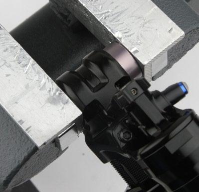
5 RockShox Service We recommend that you have your RockShox suspension serviced by a qualified bicycle mechanic. Servicing RockShox suspension requires knowledge of suspension components, as well as the use of specialized tools and lubricants/fluids. Failure to follow the procedures outlined in this service manual may cause damage to your component and void the warranty. Visit for the latest RockShox Spare Parts catalog and technical information. For order information, please contact your local SRAM distributor or dealer. Information contained in this publication is subject to change at any time without prior notice. Your product's appearance may differ from the pictures contained in this publication. For recycling and environmental compliance information, please visit Part Preparation Remove the component from the bicycle before service. Disconnect and remove the remote cable or hydraulic hose from the fork or rear shock, if applicable. For additional information about RockShox remotes, user manuals are available at Clean the exterior of the product with mild soap and water to avoid contamination of internal sealing part surfaces. Service Procedures The following procedures should be performed throughout service, unless otherwise specified. Clean the part with RockShox Suspension Cleaner or isopropyl alcohol and a clean, lint-free shop towel. Clean the sealing surface on the part and inspect it for scratches. Replace the o-ring or seal with a new one from the service kit. Use your fingers or a pick to pierce and remove the old seal or o-ring. Apply RockShox Dynamic Seal Grease to the new seal or o-ring. If a brush is used to apply grease, confirm there are no loose bristles in the grease or on the part. NOTICE Do not scratch any sealing surfaces when servicing the product. Scratches can cause leaks. Consult the spare parts catalog to replace the damaged part. To prevent damage to the shock, use aluminum soft jaws and position the eyelet in the vise so that the adjustment knobs are clear of the vise jaws. For bearing mount shocks, wrap a shop towel around the eyelet, then clamp the eyelet flat into the vise. Tighten the part with a torque wrench to the torque value listed in the red bar. When using a crowfoot socket and torque wrench, install the crowfoot socket at 90 degrees to the torque wrench. Specified torque value in N m (in-lb) RockShox Service 5
6 Recommended Service Intervals Regular service is required to keep your RockShox product working at peak performance. Follow this maintenance schedule and install the service parts included in each service kit that corresponds with the Service Hours Interval recommendation below. For spare part kit contents and details, refer to the RockShox Spare Parts Catalog at Service Hours Interval Maintenance Benefit Every ride Every 200 Hours Clean dirt from shock damper body and wiper seal Perform damper service Extends wiper seal lifespan Minimizes damage to shock damper body Minimizes oil contamination Extends suspension lifespan Restores damping performance Record Your Settings Use the charts below to record your shock settings to return your shock to its pre-service settings. Record your service date to track service intervals. Service Hours Interval Date of Service Rebound setting - Count the number of clicks while turning the rebound adjuster fully counter-clockwise. Torque Values Part Tool Torque Main piston nut 12 mm socket 8.5 N m (75 in-lb) Cap screw 3 mm hex wrench N m (18-22 in-lb) IFP reservoir 31 mm 8 N m (70 in-lb) Cable hanger screw 2 mm hex wrench 0.45 N m (4 in-lb) Remote screw T10 TORX 1.4 N m (12 in-lb) Ferrule lock screw 2 mm hex wrench 0.8 N m (7 in-lb) Cable set screw 2 mm hex wrench 0.9 N m (8 in-lb) Cable spool cap 3 mm hex wrench 0.8 N m (7 in-lb) Recommended Service Intervals 6
7 Comprehensive Parts, Tools, and Supplies List Parts Bicycle Tools Super Deluxe Coil Service Kit hours Shock pump Super Deluxe Coil Remote Service Kit hours Rear Shock Bearing Kit Safety and Protection Supplies Apron Clean, lint-free shop towels Nitrile gloves Oil pan Safety glasses Lubricants and Oils Isopropyl alcohol or RockShox Suspension Cleaner RockShox 7wt Suspension Oil RockShox Dynamic Seal Grease RockShox Tools RockShox 1/2" x 1/2" rear shock bushing removal/installation tool RockShox Air Valve Adapter Tool - Rear Shock (red adapter) RockShox Counter Measure Spring Compressor Tool RockShox Vivid /Vivid Air /Super Deluxe Coil 24 mm Spanner Wrench Schrader valve core tool Common Tools Bearing press tool: 22 mm (OD) x 10 mm (ID) Bench vise with aluminum soft jaws and grooved soft jaws Cable and housing cutters Flat wrench: 31 mm or strap wrench Hammer Hex bit sockets: 2 mm, 3 mm Hex wrenches: 1.5 mm, 2 mm, 3 mm, 5 mm Metric caliper or small metric ruler Open end wrenches: 5 mm, 13 mm (x2) Pick Small diameter punch Socket wrench: 12 mm Torque wrench T10 TORX wrench and bit socket Comprehensive Parts, Tools, and Supplies List 7


 Preload adjuster Lock")


8 Exploded View Super Deluxe Coil RCT, RC, RTR Super Deluxe Coil R Body eyelet Bushing Compression valve (RCT, RC) Compression lever (RCT) Preload adjuster Lock Spring (RTR) Lock Shim (RTR) Damper body Compression assembly (RTR shown) Main piston nut Main piston IFP reservoir Spring Counter Measure spring Seal head IFP (Internal Floating Piston) IFP bleed screw IFP reservoir cap Bottom out bumper Retaining ring Spring Retainer Shaft eyelet IFP reservoir valve cap


9 Exploded View - Remote Cap screw Travel limit screw Cam housing Spring tang Spring Spring tang Cam Threaded ferrule Cable hanger screw Ferrule lock screw Cable hanger Cable set screw Cable spool Remote screw Cable spool cap Exploded View - Bearing Mount Dust cover Bearing Spacer Bearing Dust cover


.")


10 Remote Cable and Housing Removal - RTR Only Prior to servicing the rear shock, remove the remote cable and housing from the shock, then remove the shock from the bicycle frame according to the bicycle manufacturer's instructions. Replace the cable and housing after performing shock service (see the Remote Cable and Housing Installation - RLR Only section). Parts, Tools, and Supplies Safety and Protection Supplies Safety glasses Nitrile gloves Common Tools Hex wrenches: 2 and 3 mm Cable and housing cutters 1 Remove the cable spool cap. 3 mm 2 Loosen the cable set screw, then cut the cable. Loosen the ferrule lock screw. Remove the threaded ferrule, housing, and cable from the cable bracket. Discard the threaded ferrule, cable, and housing. Cable and Housing Cutters 2 mm 3 mm Remote Cable and Housing Removal - RTR Only 10

 or")
11 Shock Eyelet Service Mounting Hardware and Bushing Service Prior to servicing the rear shock, remove it from the bicycle frame according to the bicycle manufacturer's instructions. Once the shock is removed from the bicycle, remove the mounting hardware before performing any service. Replace bushings as needed. Parts, Tools, and Supplies Parts Super Deluxe Coil Service Kit hours Super Deluxe Coil Remote Service Kit hours Safety and Protection Supplies Apron Clean, lint-free shop towels Nitrile gloves Safety glasses Lubricants and Oils RockShox Dynamic Seal Grease RockShox Tools RockShox 1/2" x 1/2" rear shock bushing removal/installation tool Common Tools Open end wrenches: 13 mm (x2) or an adjustable wrench Bench vise with aluminum soft jaws Mounting Hardware Removal Some mounting hardware is easily removed using only your fingers. Try to remove the end spacers with your fingernail or small screwdriver, then push the bushing pin out of the bushing. If this works, continue to the next section. If you are unable to remove the mounting hardware using your fingers, use the RockShox rear shock bushing removal/installation tool. Catcher Push pin Threaded rod Rear Shock Bushing Removal/Installation Tool 1 Thread the small end of the push pin onto the threaded rod until the rod is flush or slightly protrudes from the hex-shaped end of the push pin. Shock Eyelet Service 11


12 2 Insert the threaded rod through the shaft eyelet until the push pin rests against the bushing pin. Thread the large, open end of the catcher along the rod until it rests on the end spacer. 3 Hold the catcher secure with a 13 mm open end or adjustable wrench. Use a second 13 mm or adjustable wrench to thread the push pin along the rod until it stops against the end spacer. Unthread the push pin from the threaded rod to remove the end spacer and the bushing pin if it slides out easily. 13 mm 13 mm 4 If the bushing pin did not remove easily, unthread the push pin from the threaded rod to remove the end spacer, then reinstall the push pin onto the threaded rod. Thread the large, open end of the catcher along the rod until it rests against the shaft eyelet. Use a 13 mm wrench to thread the push pin along the rod until it stops against the eyelet shaft. Unthread the push pin from the threaded rod to remove the bushing pin. 13 mm 13 mm 5 Unthread the catcher from the threaded rod. Remove the end spacer and bushing pin from the tool. Repeat steps 2-5 for the damper eyelet. Set the mounting hardware aside until you have finished servicing the shock. Mounting Hardware Removal 12


13 Eyelet Bushing Removal To replace damaged or worn out bushings, use the RockShox rear shock bushing removal/installation tool. 1 Insert the threaded rod through the shaft eyelet until the base of the push pin rests against the bushing. Thread the large, open end of the catcher onto the rod until it rests on the eyelet. 2 Hold the catcher secure with a 13 mm open end or adjustable wrench. Use a second 13 mm wrench to thread the push pin along the rod until the push pin pushes the eyelet bushing out of the eyelet. 13 mm 13 mm 3 Unthread the catcher from the threaded rod. Remove the tool from the shaft eyelet and discard the bushing. Repeat steps 1-3 for the damper body eyelet. Eyelet Bushing Removal 13


14 Eyelet Bushing Installation 1 Apply a light layer of grease to the outside of the new bushing. 2 Position the shaft eyelet and eyelet bushing between the soft jaws of a vise. Slowly turn the vise handle to begin pressing the eyelet bushing into the shaft eyelet. Check the alignment of the bushing as it enters the eyelet. If the bushing starts to enter the eyelet at an angle, remove the bushing from the eyelet, regrease the bushing, and repeat this step until the bushing enters the eyelet straight. Continue to press the eyelet bushing until it is seated in the shaft eyelet. Remove the shock from the vise and repeat the installation process for the other bushing and eyelet. Eyelet Bushing Installation 14


 x 10 mm (ID) Bench vise with")

15 Bearing Mount Service Replace the bearings if they are not spinning freely, or if they are making a creaking noise. Parts, Tools, and Supplies Parts Rear Shock Bearing Kit Safety and Protection Supplies Clean, lint-free shop towels Nitrile gloves Safety glasses Lubricants and Oils Isopropyl alcohol or RockShox Suspension Cleaner Common Tools Bearing press tool: 22 mm (OD) x 10 mm (ID) Bench vise with aluminum soft jaws Hammer Small diameter punch Bearing Removal 1 Remove the dust cover. 2 Place a punch against the back of the opposite bearing, and tap out the bearing. Hammer Punch Bearing Mount Service 15


16 3 Turn the shock over and place the punch against the back of the other bearing, and tap out the bearing. Punch Hammer 4 Clean the bearing bores. Bearing Removal 16


 x 10 mm (ID) bearing press tool Bearing Press Tool 2 Insert a new spacer into the eyelet, then")

17 Bearing Installation 1 Install a new bearing into one bearing bore, then clamp the eyelet and bearing into a vise with soft jaws. Press the bearing into the bearing bore until it is flush with the eyelet. Loosen the vise, and align the bearing press tool with the bearing, then tighten the vise. Press the bearing into the bearing bore until it stops. NOTICE Do not overtighten the bearing. Overtightening can damage the bearing and cause it to malfunction. To prevent damage to the bearing, make sure that the bearing press tool contacts both the inner and outer races of the bearing. 22 mm (OD) x 10 mm (ID) bearing press tool Bearing Press Tool 2 Insert a new spacer into the eyelet, then install a new bearing into the other bearing bore. Clamp the eyelet and bearing into a vise with soft jaws, then press the bearing into the bearing bore until it is flush with the eyelet. Loosen the vise, and align the bearing press tool with the bearing, then tighten the vise. Press the bearing into the bearing bore until it stops. NOTICE Do not overtighten the bearing. Overtightening can damage the bearing and cause it to malfunction. To prevent damage to the bearing, make sure that the bearing press tool contacts both the inner and outer races of the bearing. Bearing Press Tool Bearing Installation 17

18 3 Remove the shock from the vise. The bearings should sit approximately 1 mm below the outer edge of the bearing bore. Install dust covers before installing the shock on the bicycle. Bearing Installation 18
19 Super Deluxe Coil Service Parts, Tools and Supplies Parts Super Deluxe Coil Service Kit hours Super Deluxe Coil Remote Service Kit hours Safety and Protection Supplies Apron Clean, lint-free shop towels Nitrile gloves Oil pan Safety glasses Lubricants and Oils Isopropyl alcohol or RockShox Suspension Cleaner RockShox 7wt Suspension Oil RockShox Dynamic Seal Grease RockShox Tools RockShox Air Valve Adapter Tool - Rear Shock (red adapter) RockShox Counter Measure Spring Compressor Tool RockShox Vivid /Vivid Air /Super Deluxe Coil 24 mm Spanner Wrench Bicycle Tools Schrader valve core tool Shock pump Common Tools Bench vise with aluminum soft jaws and grooved soft jaws Flat wrench: 31 mm or strap wrench Hex bit sockets: 2 mm, 3 mm Hex wrenches: 1.5 mm, 2 mm, 3 mm, 5 mm Metric caliper or small metric ruler Pick Socket wrench: 12 mm Torque wrench T10 TORX wrench and bit socket WARNING Before disassembly or service of any air system, remove the air pressure from all air chambers and remove the air valve cores. If your shock will not return to full extension, do not attempt to service or disassemble your shock. Attempting to service a shock that will not return to full extension can cause severe and/or fatal injuries. SAFETY INSTRUCTIONS Always wear safety glasses and nitrile gloves when working with suspension oil. Place an oil pan on the floor underneath the area where you will be working on the shock. Super Deluxe Coil Service 19
,")


20 Spring Removal 1 To record your adjustment settings, turn the rebound knob counter-clockwise until it stops (full fast), while counting the number of detent clicks. This will assist you with post-service set up. RCT: Turn the compression lever to the unlocked position, then turn the compression valve counter-clockwise until it stops. RC: Turn the compression valve counter-clockwise until it stops. RTR: The compression circuit is unlocked by default once the remote cable is removed. RCT RCT RC 2 Turn the preload adjuster counter-clockwise until there is a large gap between it and the spring. Spring Removal 20


21 3 Remove the spring retainer and spring. Spring Removal 21


22 Damper Service 1 Clamp the body eyelet into the vise. 2 Record your air pressure setting to assist with post-service set up. Remove the IFP reservoir valve cap. Depress the Schrader valve and release all air pressure from the IFP reservoir. Once the pressure has been released, depress the Schrader valve a second time. If the Schrader valve is able to move, the shock has been completely depressurized. If the Schrader valve does not move at all, the shock is still pressurized and will need to be sent to an authorized RockShox service center for further service. CAUTION - EYE HAZARD Verify all pressure is removed from the shock before proceeding. Failure to do so can cause the pressurized oil to spray from the shock during disassembly. Wear safety glasses. RockShox Air Valve Adapter Tool and Shock Pump Small Hex Wrench 250 psi Schrader Valve Core Tool 3 Remove the Schrader valve core from the IFP reservoir valve. Do not discard the Schrader valve core. Schrader Valve Core Tool Damper Service 22


23 4 Push the IFP reservoir cap into the reservoir until it stops. 5 Remove the retaining ring from the IFP reservoir. CAUTION - EYE HAZARD The retaining ring can eject rapidly as it is removed. Wear safety glasses. Do not scratch the inside of the IFP reservoir. 6 Remove the IFP reservoir cap from the IFP reservoir. Pick 7 Remove the IFP reservoir cap o-ring. Install a new o-ring. Apply grease to the o-ring and reservoir cap. Damper Service 23


24 8 Remove and discard the IFP bleed screw. T10 9 Move the bottom out bumper away from the seal head. Insert the spanner wrench into the pin holes of the seal head so that the arm of the wrench is away from the reservoir. Mark the holes that the wrench used. This will prevent any overlap between the tool and the reservoir during installation. Spanner Wrench 10 Loosen and slowly remove the shaft assembly from the damper body. NOTICE Hold the spanner wrench in place with your hand as you turn the seal head to prevent damage to the seal head pin holes. Oil will spill from the damper body and the reservoir mount as the shaft assembly is removed. Wrap a shop towel around the damper body. Spanner Wrench Damper Service 24


25 11 Remove the shock from the vise and pour the oil from the damper body into an oil pan. Clean the damper body. 12 Clamp the shaft eyelet into the vise. 13 Remove the main piston nut. Clean the nut and the threads of the shaft assembly to remove all traces of Loctite. NOTICE Make sure all traces of Loctite have been removed from the shaft assembly before proceeding. Failure to remove Loctite can restrict movement in the main piston assembly and reduce functionality in the shock. 12 mm Damper Service 25


26 14 Slide the main piston assembly off the shaft and onto a small hex wrench or pick. NOTICE Keep all the parts together and set them aside. If the main piston assembly is disassembled, it will need to be replaced. 15 Remove the seal head. 16 Pierce and remove the rod wiper seal and the seal head o-ring. Install a new o-ring and wiper seal. Install the wiper seal with the stepped face away from the seal head. NOTICE Do not scratch the seal head with the pick. Pick Pick 17 Remove the bottom out bumper from the shaft. Clean and inspect the shaft for damage and replace if necessary. Reinstall the bottom out bumper on the shaft assembly. Damper Service 26


27 18 Apply grease to the o-ring, bushing, and into the cavity of the wiper seal. Install the seal head onto the shaft assembly with the Counter Measure Spring oriented upward. 19 Install the main piston assembly onto the damper shaft. Squeeze the shims and center the shim stack on top of the main piston. Be sure to keep the main piston assembly parts in the same order. NOTICE If the shims are not centered and in the correct order, the shock will not perform properly. 20 Thread the nut onto the damper shaft. Tighten the main piston nut. Remove the assembly from the vise. 12 mm 8.5 N m (75 in-lb) Damper Service 27


28 IFP Reservoir Service 1 RTR: Clamp the body eyelet into the vise and remove the remote screw and the cable spool. Loosen the cable hanger screw and remove the cable hanger. T10 2 mm 2 Loosen the IFP reservoir from the eyelet. Remove the shock from the vise, hold it over an oil pan, and turn the shock over to remove the IFP reservoir by hand. Oil will spill from the IFP reservoir when it is removed. Pour the oil into an oil pan. 31 mm 3 Push the IFP out of the IFP reservoir. IFP Reservoir Service 28


29 4 Remove the IFP o-ring and clean the IFP. Apply grease to the new o-ring and install it. IFP Reservoir Service 29


30 Remote Spring Service Replacement - RTR Only 1 Pull on the compression nut while rocking it from side-to-side to remove the compression assembly from the IFP reservoir mount. 1 Remove the lock spring and lock shim and set them aside. 2 Soak up excess oil in the IFP reservoir mount. 3 Loosen the cap screw from the reservoir and remove the remote subassembly from the reservoir. 3 mm Remote Spring Service Replacement - RTR Only 30


31 4 Clean the remote subassembly. 5 Remove the shock from the vise, and install grooved soft jaws into the vise. Gently clamp the cam into the groove in the soft jaws. Preload the spring clockwise until it stops, then remove the travel limit screw. Carefully unload the spring and pull the cam from the cam housing. CAUTION If not unloaded slowly, the spring can reset rapidly, causing the hex wrench to eject from the cam assembly. Grooved Soft Jaws 5 mm 1.5 mm 5 mm 6 Remove the spring from the cam and clean the cam. NOTICE Do not spray isopropyl alcohol on the cam when o-rings are installed. Isopropyl alcohol can cause the o-rings to become brittle and break. Remote Spring Service Replacement - RTR Only 31


32 7 Apply a thick layer of grease to the cam. 8 Apply a thick layer of grease to the inside and outside of the new remote spring, then install the spring onto the cam with the spring tang in the spring tang hole. 9 Install the cam and spring into the cam housing, and rotate the cam until the spring tang falls into the tang hole. The cam should be flush with the end of the cam housing. Remote Spring Service Replacement - RTR Only 32


 5 mm 5 mm 5 mm 5 mm 11 Clean the")


33 10 Preload the spring clockwise until the threaded hole in the cam aligns with the hole in the cam housing, then install a new travel limit screw and tighten until the screw is flush. Carefully unload the spring. Place tension on the spring by preloading and unloading it to ensure it has been installed correctly. CAUTION If not unloaded slowly, the spring can reset rapidly, causing the hex wrench to eject from the cam assembly. T mm TORX 1.1 N m (10 in-lb) 5 mm 5 mm 5 mm 5 mm 11 Clean the remote subassembly. 12 Clamp the body eyelet into the vise and install the remote subassembly into the reservoir mount. The machined flat will only allow the remote subassembly to be installed one way. Tighten the cap screw. 3 mm N m (18-22 in-lb) Remote Spring Service Replacement - RTR Only 33


34 13 Install the lock spring and lock shim into the reservoir mount. RTR RTR 14 Install the compression assembly into the reservoir mount. Push the compression assembly into the reservoir until it stops. Remote Spring Service Replacement - RTR Only 34


35 Super Deluxe Coil Assembly and Bleed 1 Move the bottom out bumper away from the seal head and insert the spanner wrench into the pin holes of the seal head that you marked earlier. Spanner Wrench Super Deluxe Coil Assembly and Bleed 35


36 2 Assemble the Counter Measure Compressor so that stop 1 is at the end of the shaft, then tighten stop bolt 1. Position the Counter Measure Compressor onto the shaft assembly so that stop 1 is beneath the spanner wrench, and stop 2 is beneath the bottom out bumper. Clamp the compressor shaft into a vise, with the rebound knob clear of the vise jaws. Use your palm to press down on the main piston until the Counter Measure Spring is completely compressed. Slide stop 2 down toward the eyelet, then tighten stop bolt 2. Remove the shaft assembly from the vise and set aside. The Counter Measure spring must be completely compressed during installation into the damper body. Stop 1 Stop Bolt 1 Stop 2 Stop Bolt 2 Shaft Counter Measure Compressor Counter Measure Compressor Spanner wrench 3 mm 3 mm Super Deluxe Coil Assembly and Bleed 36


 5 Pour suspension oil into the IFP")


37 3 Clamp the body eyelet into the vise. 4 Thread the IFP reservoir onto the eyelet. Tighten the IFP reservoir. There will be a small, visible gap between the IFP reservoir and the body eyelet. This is OK. 31 mm 8 N m (70 in-lb) 5 Pour suspension oil into the IFP reservoir until it is level with the top of the IFP reservoir. Oil will begin to bleed into the damper body. Allow about half of the oil to bleed into the reservoir, then use the palm of your hand to tap down on the top of the reservoir repeatedly to move oil into the damper body. This will assist in purging air bubbles from the system. Fill the reservoir with more oil, then continue to tap on the top of the reservoir until no more bubbles emerge from the damper body. 7wt 7wt Super Deluxe Coil Assembly and Bleed 37


38 6 Once most of the oil from the IFP reservoir has moved to the damper body, use the palm of your hand to tap down on the top of the damper body repeatedly to move oil back into the reservoir. This will further assist in purging air bubbles from the system. Do not allow the oil level in the damper body or IFP reservoir to become low; this will allow air into the system. Continue this process of tapping the damper body and the reservoir until no more bubbles emerge from either side. Once the air is purged from the system, remove your hand and the oil levels will equalize on both sides. 7 Install the IFP into the damper body with the flat side visible. Use your thumb to evenly and slowly push the IFP into the reservoir until oil starts to emerge through the bleed hole. Tap the top of the damper body a few more times to push any trapped air through the IFP bleed port. When no more air bubbles emerge from the bleed port, immediately cover the damper body with your hand. 8 Cover the damper body with your hand, then install a new bleed screw into the bleed port and tighten it until the IFP begins to spin. A small amount of grease on the tip of the TORX wrench will keep the bleed screw in place while installing it. Remove your hand from the damper body. 9 Pour additional oil into the damper body until the oil is level with the top of the threads. 7wt Super Deluxe Coil Assembly and Bleed 38


39 10 Insert the shaft assembly into the damper body at a 45 degree angle while rotating the main piston into the oil in the damper body. Oil will overflow from the damper body. Place a shop towel below the shock. Place your thumb on the IFP to prevent it from moving, then slowly 11 Spanner Wrench 28.2 N m (250 in-lb) install the shaft assembly into the damper body and tighten. Pressure will continue to build against the IFP as the shaft assembly is tightened. Keep your thumb on the IFP to ensure the best bleed. Remove your thumb once the shaft assembly has been tightened. CAUTION - EYE HAZARD Oil can eject from the damper body. Wear safety glasses. 12 Remove the IFP bleed screw. T10 Super Deluxe Coil Assembly and Bleed 39


40 13 Place a shop towel around the IFP reservoir to catch oil overflow. Use a metric caliper or ruler to push the IFP into the reservoir to the depth noted below: For mm shock stroke: 33 mm For 75 mm shock stroke: 39 mm Measure the IFP depth from the lowest part of the IFP. CAUTION - EYE HAZARD Oil can eject from the IFP bleed port. Wear safety glasses mm shock stroke: 33 mm 75 mm shock stroke: 39 mm 14 Remove the shock from the vise and gently tap the shock on a bench to remove any excess bubbles from the system. 15 Clamp the body eyelet into the vise. Install the bleed screw into the bleed port and tighten until the IFP begins to spin. T10 16 Loosen a stop bolt on the Counter Measure Compressor to remove it and the spanner wrench from the shaft assembly. 3 mm Spanner Wrench Super Deluxe Coil Assembly and Bleed 40


41 17 Remove the shock from the vise and pour any excess oil that may be above the IFP into an oil pan. Wipe the inside of the IFP reservoir with a shop towel. NOTICE Do not spray isopropyl alcohol into the reservoir. Isopropyl alcohol can cause o-rings to become brittle and crack. 18 Clamp the body eyelet into the vise. 19 Push the reservoir cap into the IFP reservoir until the retaining ring groove is visible. Super Deluxe Coil Assembly and Bleed 41


42 20 Push the new retaining ring into the groove until it is seated. CAUTION- EYE HAZARD The retention ring can eject rapidly as it is installed. Wear safety glasses. 21 Pull up on the IFP reservoir cap to seat it against the retaining ring. Pick 22 Install the Schrader valve into the IFP reservoir cap. Schrader Valve Core Tool 23 Install the RockShox air valve adaptor tool onto the shock pump and thread the adaptor tool into the reservoir air valve. Inflate the reservoir to 250 psi. Remove the adaptor tool and pump from the reservoir. Separating the pump from the adapter first will allow all of the air to escape from the reservoir. You may substitute nitrogen if you have the proper fill equipment. RockShox Air Valve Adapter Tool and Shock Pump 250 psi Super Deluxe Coil Assembly and Bleed 42


 26 RTR: Install the")


43 24 Install a new IFP reservoir fill cap o-ring, and install the fill cap into the IFP reservoir cap. Schrader Valve Core Tool 25 RTR: Install the cable hanger onto the remote subassembly, then tighten the cable hanger screw. 2 mm 0.45 N m (4 in-lb) 26 RTR: Install the cable spool onto the cable hanger with the arrow pointing at the cable hanger, then tighten the remote screw. T N m (12 in-lb) 27 Clean the shock. Super Deluxe Coil Assembly and Bleed 43


44 28 Install the coil spring and spring retainer. Adjust the spring preload adjuster until the coil spring contacts the spring retainer. Ensure that there is no vertical play between the coil spring and the retainer by holding the spring and trying to pull on the shock body. NOTICE Do not exceed 5 mm (or five full turns of rotation) on the spring preload adjuster as this will damage the shock. If more than 5 turns are necessary to achieve proper sag, use a higher weight spring. 29 Refer to the rebound and compression settings that you wrote down for your shock at the beginning of the service. Set each adjuster to the recorded number of clicks/turns. Super Deluxe Coil Assembly and Bleed 44


45 Mounting Hardware Installation Some mounting hardware is easily installed using only your fingers. Press the bushing pin into the shock eyelet bushing until the pin protrudes from both sides of the eyelet an equal amount. Next, press an end spacer, large diameter side first, onto each end of the bushing pin. If this works, you have completed mounting hardware and bushing service. If you are unable to install your mounting hardware using your fingers, use the RockShox rear shock bushing removal/installation tool. 1 Thread the small end of the push pin onto the threaded rod until the push pin is flush or slightly protrudes from the hex-shaped end of the push pin. 2 Insert the threaded rod through the shaft eyelet until the push pin rests against the bushing pin. 3 Thread the large, open end of the catcher onto the rod until it rests on the eyelet. Mounting Hardware Installation 45


46 4 Clamp the catcher in a vise or hold it secure with a 13 mm wrench. Use a second 13 mm wrench to thread the push pin along the rod until it pushes the bushing pin into the shock eyelet bushing. Continue to thread the push pin until the bushing pin protrudes from both sides of the eyelet an equal amount. You may need to unthread the catcher slightly to check the bushing pin spacing. 13 mm 5 Press an end spacer, large diameter side first, onto each end of the bushing pin. 6 Reinstall the shock to your bicycle frame according to the bicycle manufacturer's instructions. This concludes the service for the RockShox Super Deluxe Coil rear shock. Mounting Hardware Installation 46


 spool bolt.")
47 Remote Cable and Housing Installation - RTR Only To install new cable and housing into the OneLoc remote, consult the OneLoc Remote User Manual on Parts, Tools, and Supplies Parts Shift cable and housing Super Deluxe Coil Remote Service Kit hours Safety and Protection Supplies Nitrile gloves Safety glasses Common Tools Cable and housing cutters Hex bit sockets: 2 and 3 mm Hex wrenches: 2 and 3 mm Open end wrench: 5 mm Torque wrench 1 After the housing has been routed and installed on the bicycle, thread a new threaded ferrule onto the housing. Do not push the housing into the threaded ferrule. 5 mm Install the threaded ferrule and housing into the cable hanger, then 2 2 mm 0.8 N m (7 in-lb) tighten the ferrule lock screw until it is flush with the cable hanger. Thread the cable through the housing, spool, and under the cable 3 2 mm 0.9 N m (8 in-lb) spool bolt. Pull the cable tight and tighten the cable set screw. Remote Cable and Housing Installation - RTR Only 47


48 4 Trim the cable, install an end cap, and tuck the cable into the pocket. Cable and Housing Cutters 5 Install the cable spool cap and tighten. The cable spool will rotate with the spool cap when tightening. Continue to rotate the spool cap clockwise until it stops, then tighten. 3 mm 0.8 N m (7 in-lb) Parts, Tools, and Supplies 48
49 This publication includes trademarks and registered trademarks of the following companies: Loctite is a registered trademark of Henkel Corporation TORX is a registered trademark of Acument Intellectual Properties, LLC
50 tmplt ASIAN HEADQUARTERS SRAM Taiwan No Chung Shan Road Shen Kang Hsiang, Taichung City Taiwan R.O.C. WORLD HEADQUARTERS SRAM LLC 1000 W. Fulton Market, 4th Floor Chicago, Illinois USA EUROPEAN HEADQUARTERS SRAM Europe Paasbosweg ZS Nijkerk The Netherlands
PREDICTIVE STEERING HUBS. Service Manual
 2015 PREDICTIVE STEERING HUBS Service Manual SRAM LLC WARRANTY EXTENT OF LIMITED WARRANTY Except as otherwise set forth herein, SRAM warrants its products to be free from defects in materials or workmanship
2014-Present Vivid Service Manual
 2014-Present Vivid Service Manual SRAM LLC WARRANTY Extent of Limited WARRANTY Except as otherwise set forth herein, SRAM warrants its products to be free from defects in materials or workmanship for a
Predictive Steering Hub Service Manual
 Predictive Steering Hub Service Manual GEN.000000004673 Rev C 2015 SRAM, LLC SRAM LLC WARRANTY EXTENT OF LIMITED WARRANTY Except as otherwise set forth herein, SRAM warrants its products to be free from
77/177 & 76/176 Hubs. service manual. GEN Rev C 2017 SRAM, LLC
 77/177 & 76/176 Hubs service manual GEN.0000000004927 Rev C 2017 SRAM, LLC SRAM LLC WARRANTY EXTENT OF LIMITED WARRANTY Except as otherwise set forth herein, SRAM warrants its products to be free from
2017 Super Deluxe. 50 Hour Service. Service Manual. GEN Rev A 2016 SRAM, LLC
 2017 Super Deluxe 50 Hour Service Service Manual GEN.0000000005139 Rev A 2016 SRAM, LLC SRAM LLC WARRANTY EXTENT OF LIMITED WARRANTY Except as otherwise set forth herein, SRAM warrants its products to
Cognition TM. Hubs Service Manual. GEN Rev B 2017 SRAM, LLC
 Cognition TM Hubs Service Manual GEN.0000000005069 Rev B 2017 SRAM, LLC SRAM LLC WARRANTY EXTENT OF LIMITED WARRANTY Except as otherwise set forth herein, SRAM warrants its products to be free from defects
2018 Super Deluxe. service manual. GEN Rev D 2018 SRAM, LLC
 2018 Super Deluxe service manual GEN.0000000005317 Rev D 2018 SRAM, LLC SRAM LLC WARRANTY EXTENT OF LIMITED WARRANTY Except as otherwise set forth herein, SRAM warrants its products to be free from defects
Charger 2 Damper. Upgrade Kit service manual. GEN Rev B 2018 SRAM, LLC
 Charger 2 Damper Upgrade Kit service manual GEN.0000000005353 Rev B 2018 SRAM, LLC SRAM LLC WARRANTY EXTENT OF LIMITED WARRANTY Except as otherwise set forth herein, SRAM warrants its products to be free
Charger 2 Damper. Upgrade Kit service manual. GEN Rev C 2018 SRAM, LLC
 Charger 2 Damper Upgrade Kit service manual GEN.0000000005353 Rev C 2018 SRAM, LLC SRAM LLC WARRANTY EXTENT OF LIMITED WARRANTY Except as otherwise set forth herein, SRAM warrants its products to be free
SEKTOR/RECON/XC32. Service Manual
 2015 SEKTOR/RECON/XC32 Service Manual SRAM LLC WARRANTY EXTENT OF LIMITED WARRANTY Except as otherwise set forth herein, SRAM warrants its products to be free from defects in materials or workmanship for
2013 Monarch RT3 Relay Service Manual
 2013 Monarch RT3 Relay Service Manual GEN.0000000004235 Rev A 2013 SRAM LLC SRAM LLC WARRANTY Extent of Limited Warranty Except as otherwise set forth herein, SRAM warrants its products to be free from
Cognition Disc Hubs service
 Cognition Disc Hubs Cognition Disc Hubs service service manual GEN.0000000005343 Rev A 2017 SRAM, LLC SRAM LLC WARRANTY EXTENT OF LIMITED WARRANTY Except as otherwise set forth herein, SRAM warrants its
XC 28 & XC 30 Service Manual
 XC 28 & XC 30 Service Manual GEN0000000004936 Rev B 2015 SRAM, LLC SRAM LLC WARRANTY EXTENT OF LIMITED WARRANTY Except as otherwise set forth herein, SRAM warrants its products to be free from defects
PRESENT. VIVID AIR SERVICE MANUAL Service Manual
 2014 - PRESENT VIVID AIR SERVICE MANUAL Service Manual SRAM LLC WARRANTY EXTENT OF LIMITED WARRANTY Except as otherwise set forth herein, SRAM warrants its products to be free from defects in materials
2013 Monarch RL Service Manual
 2013 Monarch RL Service Manual GEN.0000000004177 Rev A Copyright 2012 SRAM, LLC SRAM LLC WARRANTY Extent of Limited Warranty Except as otherwise set forth herein, SRAM warrants its products to be free
Double Time Hubs RISE XX, RISE 60, ROAM 40, ROAM 30, RAIL 40, AND X0 HUBS Instructions apply to classic and Boost hub sizes
 Double Time Hubs RISE XX, RISE 60, ROAM 40, ROAM 30, RAIL 40, AND X0 HUBS Instructions apply to classic and Boost hub sizes Service Manual GEN.0000000004979 Rev A 2015 SRAM, LLC SRAM LLC WARRANTY EXTENT
Level /Level T
 2016-2019 Level /Level T service manual GEN.0000000005817 Rev A 2018 SRAM, LLC SRAM LLC WARRANTY EXTENT OF LIMITED WARRANTY Except as otherwise set forth herein, SRAM warrants its products to be free from
404 Firestrike. Service Manual. GEN Rev B 2015 SRAM, LLC
 404 Firestrike Service Manual GEN.0000000004724 Rev B 2015 SRAM, LLC SRAM LLC WARRANTY EXTENT OF LIMITED WARRANTY Except as otherwise set forth herein, SRAM warrants its products to be free from defects
Monarch. RT3/R Service Manual. GEN Rev B 2016 SRAM, LLC
 Monarch RT3/R Service Manual GEN.0000000004932 Rev B 2016 SRAM, LLC SRAM LLC WARRANTY EXTENT OF LIMITED WARRANTY Except as otherwise set forth herein, SRAM warrants its products to be free from defects
Monarch Plus RC3/R. Service Manual. GEN Rev B 2016 SRAM, LLC
 Monarch Plus RC3/R Service Manual GEN.0000000004938 Rev B 2016 SRAM, LLC SRAM LLC WARRANTY EXTENT OF LIMITED WARRANTY Except as otherwise set forth herein, SRAM warrants its products to be free from defects
S-900 Aero HRD. Lever / Caliper / Hose Replacement. service manual. GEN Rev A 2017 SRAM, LLC
 S-900 Aero HRD Lever / Caliper / Hose Replacement service manual GEN.0000000005452 Rev A 2017 SRAM, LLC SRAM LLC WARRANTY EXTENT OF LIMITED WARRANTY Except as otherwise set forth herein, SRAM warrants
Sektor, Recon, 30 Gold, 30 Silver
 Sektor, Recon, 30 Gold, 30 Silver Service Manual GEN.0000000004923 Rev A 2015 SRAM, LLC SRAM LLC WARRANTY EXTENT OF LIMITED WARRANTY Except as otherwise set forth herein, SRAM warrants its products to
Deluxe. service manual. GEN Rev A 2018 SRAM, LLC
 2018-2019 Deluxe service manual GEN.0000000005708 Rev A 2018 SRAM, LLC SRAM LLC WARRANTY EXTENT OF LIMITED WARRANTY Except as otherwise set forth herein, SRAM warrants its products to be free from defects
2017 Reverb Stealth. Service Manual. GEN Rev B 2016 SRAM, LLC
 2017 Reverb Stealth Service Manual GEN.0000000005101 Rev B 2016 SRAM, LLC SRAM LLC WARRANTY EXTENT OF LIMITED WARRANTY Except as otherwise set forth herein, SRAM warrants its products to be free from defects
Reverb Stealth & Reverb
 Reverb Stealth & Reverb Hydraulic Hose Replacement Remote System Bleed bleed manual GEN.0000000005105 Rev B 2017 SRAM, LLC SRAM LLC WARRANTY EXTENT OF LIMITED WARRANTY Except as otherwise set forth herein,
, Judy, & Recon
 2018-2019 30, Judy, & Recon service manual GEN.0000000005335 Rev D 2018 SRAM, LLC SRAM LLC WARRANTY EXTENT OF LIMITED WARRANTY Except as otherwise set forth herein, SRAM warrants its products to be free
REBA and Bluto service manual
 2017-2019 REBA and Bluto service manual GEN0000000005114 Rev D 2018 SRAM, LLC SRAM LLC WARRANTY EXTENT OF LIMITED WARRANTY Except as otherwise set forth herein, SRAM warrants its products to be free from
Reverb A2 & B1. service manual. GEN Rev A 2017 SRAM, LLC
 Reverb A2 & B1 service manual GEN.0000000005342 Rev A 2017 SRAM, LLC SRAM LLC WARRANTY EXTENT OF LIMITED WARRANTY Except as otherwise set forth herein, SRAM warrants its products to be free from defects
Roam 60/50, Rail Service Manual
 Roam 60/50, Rail 50 2014-2016 Service Manual GEN. 0000000004463 Rev B 2015 SRAM, LLC SRAM LLC WARRANTY EXTENT OF LIMITED WARRANTY Except as otherwise set forth herein, SRAM warrants its products to be
Reverb Stealth A2 & B1
 Reverb Stealth A2 & B1 service manual GEN.0000000005341 Rev B 2017 SRAM, LLC SRAM LLC WARRANTY EXTENT OF LIMITED WARRANTY Except as otherwise set forth herein, SRAM warrants its products to be free from
BoXXer RC. Service Manual. GEN Rev A 2018 SRAM, LLC
 2015-2018 BoXXer RC Service Manual GEN.0000000005717 Rev A 2018 SRAM, LLC SRAM LLC WARRANTY EXTENT OF LIMITED WARRANTY Except as otherwise set forth herein, SRAM warrants its products to be free from defects
Monarch XX/RL/RT. Service Manual. GEN Rev B 2016 SRAM, LLC
 Monarch XX/RL/RT Service Manual GEN.0000000004933 Rev B 2016 SRAM, LLC SRAM LLC WARRANTY EXTENT OF LIMITED WARRANTY Except as otherwise set forth herein, SRAM warrants its products to be free from defects
2017 Reverb. service manual. GEN Rev A 2016 SRAM, LLC
 2017 Reverb service manual GEN.0000000005109 Rev A 2016 SRAM, LLC SRAM LLC WARRANTY EXTENT OF LIMITED WARRANTY Except as otherwise set forth herein, SRAM warrants its products to be free from defects in
service manual
 2017-2020 service manual GEN0000000005880 Rev A 2019 SRAM, LLC SRAM LLC WARRANTY EXTENT OF LIMITED WARRANTY Except as otherwise set forth herein, SRAM warrants its products to be free from defects in materials
2018 Code RSC / R service manual
 2018 Code RSC / R service manual GEN 0000000005248 Rev C 2017 SRAM, LLC SRAM LLC WARRANTY EXTENT OF LIMITED WARRANTY Except as otherwise set forth herein, SRAM warrants its products to be free from defects
2019 Sektor. service manual. GEN Rev A 2018 SRAM, LLC
 2019 Sektor service manual GEN.0000000005641 Rev A 2018 SRAM, LLC SRAM LLC WARRANTY EXTENT OF LIMITED WARRANTY Except as otherwise set forth herein, SRAM warrants its products to be free from defects in
DebonAir Upgrade and Travel Change Kit
 DebonAir Upgrade and Travel Change Kit 35 mm Forks Lyrik B1 (2016+) PIKE A1-A2 (2014-2017) PIKE B1 (2018+) Revelation A1 (2018+) Yari A1 (2016+) BoXXer C1 (2019+) service manual GEN.0000000005734 Rev A
Lyrik. service manual. GEN Rev D 2016 SRAM, LLC
 2016-2017 Lyrik service manual GEN.0000000005042 Rev D 2016 SRAM, LLC SRAM LLC WARRANTY EXTENT OF LIMITED WARRANTY Except as otherwise set forth herein, SRAM warrants its products to be free from defects
HydroR Disc Brake. Caliper/Master Piston/ Hose Replacement. service manual. GEN Rev D 2018 SRAM, LLC
 HydroR Disc Brake Caliper/Master Piston/ Hose Replacement service manual GEN0000000005217 Rev D 2018 SRAM, LLC SRAM LLC WARRANTY EXTENT OF LIMITED WARRANTY Except as otherwise set forth herein, SRAM warrants
RS-1. Service Manual
 2015 RS-1 Service Manual SRAM LLC WARRANTY EXTENT OF LIMITED WARRANTY Except as otherwise set forth herein, SRAM warrants its products to be free from defects in materials or workmanship for a period of
HydroR Disc Brake Caliper/Master Piston/Hose Replacement
 HydroR Disc Brake Caliper/Master Piston/Hose Replacement service manual GEN0000000005217 Rev B 2017 SRAM, LLC SRAM LLC WARRANTY EXTENT OF LIMITED WARRANTY Except as otherwise set forth herein, SRAM warrants
2014-Present Pike Instructions apply to 15x100 and Boost 110 forks. Specific part information can be found in the Spare Parts Catalog.
 2014-Present Pike Instructions apply to 15x100 and Boost 110 forks. Specific part information can be found in the Spare Parts Catalog. Service Manual GEN.0000000004461 Rev D 2015 SRAM, LLC SRAM LLC WARRANTY
2016 Lyrik. Service Manual. GEN Rev C 2016 SRAM, LLC
 2016 Lyrik Service Manual GEN.0000000005042 Rev C 2016 SRAM, LLC SRAM LLC WARRANTY EXTENT OF LIMITED WARRANTY Except as otherwise set forth herein, SRAM warrants its products to be free from defects in
2017 Guide RE. service manual. Gen Rev B 2016 SRAM, LLC
 2017 Guide RE service manual Gen.0000000005128 Rev B 2016 SRAM, LLC SRAM LLC WARRANTY EXTENT OF LIMITED WARRANTY Except as otherwise set forth herein, SRAM warrants its products to be free from defects
SID, REVELATION, & BLUTO RCT3
 SID, REVELATION, & BLUTO RCT3 Service Manual GEN.0000000004976 Rev A 2015 SRAM, LLC SRAM LLC WARRANTY EXTENT OF LIMITED WARRANTY Except as otherwise set forth herein, SRAM warrants its products to be free
Guide RSC. service manual. GEN Rev A 2018 SRAM, LLC
 2017-2019 Guide RSC service manual GEN.0000000005797 Rev A 2018 SRAM, LLC SRAM LLC WARRANTY EXTENT OF LIMITED WARRANTY Except as otherwise set forth herein, SRAM warrants its products to be free from defects
BoXXer Team
 2015-2018 BoXXer Team Service Manual GEN.0000000005721 Rev A 2018 SRAM, LLC SRAM LLC WARRANTY EXTENT OF LIMITED WARRANTY Except as otherwise set forth herein, SRAM warrants its products to be free from
Level Ultimate, TLM & TL Service Manual
 Level Ultimate, TLM & TL Service Manual GEN.0000000005086 Rev A 2016 SRAM, LLC 1 SRAM LLC WARRANTY EXTENT OF LIMITED WARRANTY Except as otherwise set forth herein, SRAM warrants its products to be free
2019 PIKE & Revelation
 2019 PIKE & Revelation service manual GEN.0000000005683 Rev B 2018 SRAM, LLC SRAM LLC WARRANTY EXTENT OF LIMITED WARRANTY Except as otherwise set forth herein, SRAM warrants its products to be free from
2019 Lyrik & Yari. service manual. GEN Rev A 2018 SRAM, LLC
 2019 Lyrik & Yari service manual GEN.0000000005684 Rev A 2018 SRAM, LLC SRAM LLC WARRANTY EXTENT OF LIMITED WARRANTY Except as otherwise set forth herein, SRAM warrants its products to be free from defects
2015-Present BoXXer World Cup
 2015-Present BoXXer World Cup Service Manual GEN.0000000004665 Rev D 2016 SRAM, LLC SRAM LLC WARRANTY EXTENT OF LIMITED WARRANTY Except as otherwise set forth herein, SRAM warrants its products to be free
PIKE, REVELATION
 2019-2020 PIKE, REVELATION SERVICE MANUAL GEN.0000000005894 Rev A 2019 SRAM, LLC SRAM LLC WARRANTY EXTENT OF LIMITED WARRANTY Except as otherwise set forth herein, SRAM warrants its products to be free
SID. service manual. GEN Rev E 2018 SRAM, LLC
 2017-2019 SID service manual GEN.0000000005125 Rev E 2018 SRAM, LLC SRAM LLC WARRANTY EXTENT OF LIMITED WARRANTY Except as otherwise set forth herein, SRAM warrants its products to be free from defects
GUIDE DB5, R & RS. Service Manual
 2015 GUIDE DB5, R & RS Service Manual SRAM LLC WARRANTY EXTENT OF LIMITED WARRANTY Except as otherwise set forth herein, SRAM warrants its products to be free from defects in materials or workmanship for
Level Ultimate, TLM, & TL
 2016-2019 Level Ultimate, TLM, & TL service manual GEN.0000000005806 Rev A 2018 SRAM, LLC SRAM LLC WARRANTY EXTENT OF LIMITED WARRANTY Except as otherwise set forth herein, SRAM warrants its products to
RS-1. service manual. GEN Rev E 2017 SRAM, LLC
 2015-2018 RS-1 service manual GEN.0000000004726 Rev E 2017 SRAM, LLC SRAM LLC WARRANTY EXTENT OF LIMITED WARRANTY Except as otherwise set forth herein, SRAM warrants its products to be free from defects
SUSPENSION FORK OIL, AIR, AND COIL CHARTS
 2014 SUSPENSION FORK OIL, AIR, AND COIL CHARTS GEN.0000000004392 Rev A 2013 SRAM LLC RockShox Oil Volume Chart Drive Side Non-Drive Side Fork Model Damper Technology Upper Tube Volume (ml) Oil wt Lower
Shock Absorber Rebuild Manual
 Shock Absorber Rebuild Manual Model PODIUM RC3 FOX RACING SHOX 130 Hangar Way, Watsonville, CA 95076 PHONE 800.369.7469 FAX 831.768.7026 Email: psservicemw@ridefox.com Website: www.ridefox.com Disclaimer
2013 X0 Trail Service Manual
 2013 X0 Trail Service Manual GEN.0000000004233 Rev A 2012 SRAM LLC SRAM LLC WARRANTY Extent of Limited Warranty Except as otherwise set forth herein, SRAM warrants its products to be free from defects
Hayes Performance Systems 5800 W. Donges Bay Rd. Mequon, WI Tel: Web:
 Hayes Performance Systems 5800 W. Donges Bay Rd. Mequon, WI 53092 Tel: 888.686.3472 Email: techsupport@hayesbicycle.com Web: www.hayescomponents.com Hayes Components Europe Dirnismaning 20 a 85748 Garching
Installation & Set-Up Instructions
 Installation & Set-Up Instructions Hayes Performance Systems 5800 W. Donges Bay Rd. Mequon, WI 53092 Tel: 888.686.3472 Email: techsupport@hayesbicycle.com Web: www.hayescomponents.com Hayes Components
Hayes Performance Systems 5800 W. Donges Bay Rd. Mequon, WI Tel: Web:
 Hayes Performance Systems 5800 W. Donges Bay Rd. Mequon, WI 53092 Tel: 888.686.3472 Email: techsupport@hayesbicycle.com Web: www.hayescomponents.com Hayes Components Europe Dirnismaning 20 a 85748 Garching
Hayes Performance Systems 5800 W. Donges Bay Rd. Mequon, WI Tel: Web:
 Hayes Performance Systems 5800 W. Donges Bay Rd. Mequon, WI 53092 Tel: 888.686.3472 Email: techsupport@hayesbicycle.com Web: www.hayescomponents.com Hayes Components Europe Dirnismaning 20 a 85748 Garching
2006 SID SERVICE GUIDE
 2006 SID SERVICE GUIDE For exploded diagram and part number information, refer to the Spare Parts Catalog available on our website at www.rockshox.com. Information contained in this publication is subject
Hayes Performance Systems 5800 W. Donges Bay Rd. Mequon, WI Tel: Web:
 Hayes Performance Systems 5800 W. Donges Bay Rd. Mequon, WI 53092 Tel: 888.686.3472 Email: techsupport@hayesbicycle.com Web: www.hayescomponents.com Hayes Components Europe Dirnismaning 20 a 85748 Garching
Service & Bleed Guide
 Service & Bleed Guide Hayes Performance Systems 5800 W. Donges Bay Rd. Mequon, WI 53092 Tel: 888.686.3472 Email: techsupport@hayesbicycle.com Web: www.hayescomponents.com Hayes Components Europe Dirnismaning
Hayes Performance Systems 5800 W. Donges Bay Rd. Mequon, WI Tel: Web:
 PRO/Comp Hayes Performance Systems 5800 W. Donges Bay Rd. Mequon, WI 53092 Tel: 888.686.3472 Email: techsupport@hayesbicycle.com Web: www.hayescomponents.com Hayes Components Europe Dirnismaning 20 a 85748
TOPAZ Service Guide. Full Service
 TOPAZ Service Guide Full Service SERVICE OVERVIEW This manual will guide you step by step performing an air service to your Topaz. Please follow each instruction carefully to achieve the best and safest
For exploded diagram and part number information, refer to the Spare Parts Catalog available on our website at
 For exploded diagram and part number information, refer to the Spare Parts Catalog available on our website at www.rockshox.com. Information contained in this publication is subject to change at anytime
2006 RECON SERVICE GUIDE
 2006 RECON SERVICE GUIDE For exploded diagram and part number information, refer to the Spare Parts Catalog available on our website at www.rockshox.com. Information contained in this publication is subject
Sachs shock manual. ( ) 2 & 4 Stroke RR Enduro. ( ) RS Dual Sport
 2 & 4 Stroke RR Enduro. ( ) RS Dual Sport") Sachs shock manual (2013 2015) 2 & 4 Stroke RR Enduro (2014-2015) RS Dual Sport 1 Introduction The procedures in this manual must take place in a clean environment using professional tools and some specific,
Sachs shock manual (2013 2015) 2 & 4 Stroke RR Enduro (2014-2015) RS Dual Sport 1 Introduction The procedures in this manual must take place in a clean environment using professional tools and some specific,
SID REAR SERVICE GUIDE
 2003-2004 SID REAR SERVICE GUIDE For exploded diagram and part number information, refer to the Spare Parts Catalog available on our website at www.rockshox.com. Contact your local distributor or visit
Sachs 48mm Closed Cartridge fork Service Manual
 Sachs 48mm Closed Cartridge fork Service Manual 1 Fork seal driver 2 Special soft jaws 3 Fork cap wrench 4 Rebound rod holding tool 5 Compression assembly holding tool 6 Retaining clip tool Special Tools
Elixir 5 Service Manual
 2012 Elixir 5 Service Manual GEN.0000000003519 Rev C sram LLC warranty SRAM warrants its products to be free from defects in materials or workmanship for a period of two years after original purchase.
TK08 TUNING KIT TECHNICAL MANUAL FOR 16/26/27/28 SERIES SHOCKS Revised 6/25/14 Tech Line: (952) Fax (952)
 Fax (952)") Tech Line: (952) 985-5675 Fax (952) 985-5679 21730 Hanover Ave. Lakeville, MN 55044 www.qa1.net www.facebook.com/qa1motorsports TK08 TUNING KIT TECHNICAL MANUAL CONTENTS UNDER PRESSURE! USE EXTREME CAUTION
Tech Line: (952) 985-5675 Fax (952) 985-5679 21730 Hanover Ave. Lakeville, MN 55044 www.qa1.net www.facebook.com/qa1motorsports TK08 TUNING KIT TECHNICAL MANUAL CONTENTS UNDER PRESSURE! USE EXTREME CAUTION
SANTA CRUZ BICYCLES MY18 Nomad Suspension Setup
 SANTA CRUZ BICYCLES MY18 Nomad Suspension Setup Copyright Santa Cruz Bicycles 2017 TABLE OF CONTENTS SAFETY INSTRUCTIONS... 3 SAG SETUP...3 AIR SPRING FORKS...3 AIR SHOCKS...3 COIL SHOCKS...4 FORK SETUP...
For exploded diagram and part number information, refer to the Spare Parts Catalog available on our website at
 For exploded diagram and part number information, refer to the Spare Parts Catalog available on our website at www.rockshox.com. Contact your local distributor or visit the RockShox website at www.rockshox.com
Juicy Seven, Juicy Carbon & Juicy Five. Installation and Setup Guide
 Juicy Seven, Juicy Carbon & Juicy Five Installation and Setup Guide PLEASE READ THE SAFETY AND WARRANTY INFORMATION INSIDE 955-310588-000 Rev. C SRAM Corporation, 2006 Juicy TM Installation & Setup Guide
(english) technical manual. part#
 technical manual. part#") 008 (english) technical manual part# 95-4015-016-000 SRAM original Parts Caution: The SRAM Warranty policy does not cover damages caused by the use of non-sram parts. Use only SRAM parts with SRAM components.
008 (english) technical manual part# 95-4015-016-000 SRAM original Parts Caution: The SRAM Warranty policy does not cover damages caused by the use of non-sram parts. Use only SRAM parts with SRAM components.
TK08 TUNING KIT TECHNICAL MANUAL FOR 16/26/27/28 SERIES SHOCKS Revised 6/17/14
 Tech Line: (952) 985-5675 Fax (952) 985-5679 21730 Hanover Ave. Lakeville, MN 55044 www.qa1.net www.facebook.com/qa1motorsports TK08 TUNING KIT TECHNICAL MANUAL CONTENTS UNDER PRESSURE! USE EXTREME CAUTION
Front Suspension. Setup and Tuning Guide
 Front Suspension Setup and Tuning Guide GEN.00000000005623 GEN0000000000000 Rev A 2015 SRAM, 2018 SRAM, LLC LLC Table of Contents Introduction... 4 Set Sag...5 Dampers... 6 Air Springs - Solo Air, DebonAir,
2011 Technical Manual
 2011 Technical Manual sram LLC warranty SRAM warrants its products to be free from defects in materials or workmanship for a period of two years after original purchase. This warranty only applies to the
SANTA CRUZ BICYCLES MY17 Nomad Suspension Setup
 SANTA CRUZ BICYCLES MY17 Nomad Suspension Setup Copyright Santa Cruz Bicycles 2017 TABLE OF CONTENTS SAFETY INSTRUCTIONS... 3 SAG SETUP...3 AIR SPRING FORKS...3 AIR SHOCKS...3 FORK SETUP... 4 LYRIK SOLO
2011 Technical Manual
 2011 Technical Manual sram LLC warranty SRAM warrants its products to be free from defects in materials or workmanship for a period of two years after original purchase. This warranty only applies to the
Giant Hydraulic Disc Brake System
 Giant Hydraulic Disc Brake System INSTALLATION INSTRUCTI IMPORTANT NOTICE Contact the place of purchase or Authorized Giant Retailer for information on detail of installation and maintenance. Read this
SANTA CRUZ BICYCLES MY18 Hightower Suspension Setup
 SANTA CRUZ BICYCLES MY18 Hightower Suspension Setup Copyright Santa Cruz Bicycles 2017 TABLE OF CONTENTS SAFETY INSTRUCTIONS... 3 SAG SETUP...3 AIR SPRING FORKS...3 AIR SHOCKS...3 FORK SETUP... 4 FOX 36
(english) technical manual. part#
 technical manual. part#") 008 (english) technical manual part# 95-5015-011-000 SRAM original Parts Caution: The SRAM Warranty policy does not cover damages caused by the use of non-sram parts. Use only SRAM parts with SRAM components.
008 (english) technical manual part# 95-5015-011-000 SRAM original Parts Caution: The SRAM Warranty policy does not cover damages caused by the use of non-sram parts. Use only SRAM parts with SRAM components.
WARRANTY INFORMATION AMERICAN MADE MANITOU SUSPENSION
 AMERICAN MADE MANITOU SUSPENSION CONGRATULATIONS ON CHOOSING THE LATEST IN SUSPENSION TECHNOLOGY AVAILABLE, A 2003 MANITOU DORADO FORK BUILT IN THE USA. This DORADO fork is fully assembled and is ready
PIKE DUAL AIR PICTORIAL INSTRUCTIONS. INSTRUCTIONS FOR INSTALLING ENDURO FORK SEALS AND CHANGING SEMI-BATH OIL in RockShox PIKE Dual Air Forks
 INSTRUCTIONS FOR INSTALLING ENDURO FORK SEALS AND CHANGING SEMI-BATH OIL in RockShox PIKE Dual Air Forks RECOMMENDED PARTS AND TOOLS -Bicycle work stand -Plastic bucket/drain pan -5mm Allen wrench -DH
PILOT SL & XC SERVICE GUIDE
 For exploded diagram and part number information, refer to the Spare Parts Catalog available on our website at www.rockshox.com. 2003-2004 PILOT SL & XC SERVICE GUIDE Contact your local distributor or
Installation Manual TWM Performance Short Shifter Cobalt SS/SC, SS/TC, HHR SS, Ion Redline and Saab 9-3
 Page 1 Installation Manual TWM Performance Short Shifter Cobalt SS/SC, SS/TC, HHR SS, Ion Redline and Saab 9-3 Please Note: It is preferable to park on a flat surface, as you will have to engage and disengage
Shock Absorber Rebuild Manual
 Shock Absorber Rebuild Manual Model PODIUM X FOX RACING SHOX 130 Hangar Way, Watsonville, CA 95076 PHONE 800.369.7469 ext. 7647 FAX 831.768.7026 Email: info@foxracingshox.com Website: www.foxracingshox.com
FOX Racing Shox Bypass Technical Manual.
 FOX Racing Shox Bypass Technical Manual. The following technical manual will be using a 2.5 dia. shock with three tubes for descriptions and illustrations. Your shock may differ in the number of tubes,
Maverick American 3085 Bluff Street Boulder, CO Tel: Fax: ML7.2 SHOCK SERVICE MANUAL
 Maverick American 3085 Bluff Street Boulder, CO 80301 Tel: 303-415-0370 Fax: 303-415-0676 www.maverickamerican.com ML7.2 SHOCK SERVICE MANUAL 1. OVERVIEW 1.1. The Maverick ML7.2 rear shock is an oil damped
AEROMOTIVE Part # /2 4.6L SOHC Ford Fuel Rail Kit INSTALLATION INSTRUCTIONS
 AEROMOTIVE Part # 14125 96-98 1/2 4.6L SOHC Ford Fuel Rail Kit INSTALLATION INSTRUCTIONS CAUTION: Installation of this product requires detailed knowledge of automotive systems and repair procedures. We
Model year 2014 USER MANUAL
 Model year 2014 USER MANUAL WARRANTY Terms and conditions BOS MTB offers warranty on its products on the following terms: BOS MTB guarantees to the original purchaser that the BOS product for which they
AEROMOTIVE Part # and F-Body Fuel System Kit INSTALLATION INSTRUCTIONS
 AEROMOTIVE Part # 17101 and 17102 93-97 F-Body Fuel System Kit INSTALLATION INSTRUCTIONS CAUTION: Installation of this product requires detailed knowledge of automotive systems and repair procedures. We
Table of Contents Safety Warning Information
 SUSPENSION FORK INSTRUCTION MANUAL 2 Table of Contents 04... Safety Warning Information 05... Tools Needed 06... Fork Features Overview 07... Crown Race Installation/Steer Tube Cutting 08... Star Nut/Stem
DISC BRAKE/DUAL MASTER CYLINDER CONVERSION. Tools, Equipment and Supplies Needed:
 Please take the time to read the enclosed instructions carefully. If you have any questions, call our Product Assistance personnel for clarification. It is important to note that these instructions contain
Maverick American 3085 Bluff Street Boulder, CO Tel: Fax: ML7.0 SHOCK SERVICE MANUAL
 Maverick American 3085 Bluff Street Boulder, CO 80301 Tel: 303-415-0370 Fax: 303-415-0676 www.maverickamerican.com ML7.0 SHOCK SERVICE MANUAL 1. OVERVIEW 1.1. The Maverick ML7.0 rear shock is an oil damped