Hydraulic Disc Brake, Installation, Maintenance, and Service Manual. HFX-Mag HFX-Mag Plus HFX-9 HFX-9 HD
|
|
|
- Owen Jennings
- 6 years ago
- Views:
Transcription
1 Hydraulic Disc Brake, Installation, Maintenance, and Service Manual HFX-Mag HFX-Mag Plus HFX-9 HFX-9 HD 1
2 Introduction to this Manual This manual is intended to provide the information necessary for normal maintenance and service of the Hayes Disc Brake system. Although the steps and procedures are relatively simple, they should not be attempted until you are thoroughly familiar with the entire set of procedures. Photographs of actual hardware have been provided to help you in the steps and procedures. Cautions, Warnings, Notes, etc Within this manual are specifically labeled comments intended to bring special attention to a general procedure or detailed steps. Be aware of, and understand, the meaning of these labels. Warning: Means that there is the possibility of personal injury to yourself or to others. Caution: Means that there is the possibility of damaging the brake or the bike. Note: Provides general information. Hint: Provides information that can help you properly complete a specific procedure. Glossary To help you become familiar with some of the terms associated with disc brakes, and in particular the Hayes Disc Brake, we provide the following glossary. Burnish: The breaking in period of a disc brake system until the brake achieves full power. Bleed: Removing the air from a full hydraulic system. Bladder: The part on the Hayes Disc Brake system that contains the fluid reservoir. The bladder expands as the fluid heats up and expands, and contracts as the caliper pistons move out as the brake pads wear. Full Hydraulic: A Hydraulic system where pressure is generated directly through activation of the lever. Master Cylinder: The part on the Hayes Disc Brake system that generates pressure in the full hydraulic system. The master cylinder is activated through the lever. Caliper: The part of the Hayes Disc Brake system that holds the brake pads, and clamps on the disc to slow the wheel. 2
3 Starting Out Recommended Fluids and Lubricants Use only DOT 3 or DOT 4 brake fluid. Do not use any petroleum-based lubricants, as this will cause the rubber parts to swell. Hayes recommends the use of DOT 4 or DOT 3 brake fluid. Clean the disc and pads only with isopropyl alcohol. Personal Preference Adjustments In most cases, the Hayes Disc Brake system has been pre-assembled for your bike. However there are a couple of adjustments that you can make to match your particular physical characteristics or personal preferences. Positioning the Master Cylinder and Lever 1. Loosen, but do not remove, the handlebar clamp screw. 2. Then, position the Master Cylinder and Lever on the handlebar in your desired position. 3. Torque the handlebar clamp screw to: HFX Mag or Mag Plus: in-lbs ( Nm). HFX 9: in-lbs ( Nm). Lever Reach Adjustment 1. Adjust the brake lever reach by using a 2.0 mm Allen wrench and turning the push rod that goes through the lever adjusting bushing. Do not attempt to force the adjustment screw beyond its limits. Burnish Disc brakes require a special burnish period to achieve maximum braking power. This burnishing period lasts for about stops. During this period some noise may occur. Safety Info This brake has been designed for use on a single person mountain bike. The use on any other vehicle or device will void the warranty and can cause serious injury. For riders using the brakes in downhill conditions, it is recommended that you use the 8" version of the Hayes brake. This includes the HFX-Mag or HFX-9 HD Hayes brakes with 8" discs. Not all frames and forks will accept an 8" disc. Please check with your frame and fork manufacturer or for 8" disc compatibility. Consistently using the 6" disc in downhill conditions may cause the brake fluid to boil. As a serious rider you are probably well aware of the need to practice safety in all aspects of the sport. This includes service and maintenance practices as well as riding practices. Before each ride, always check your brakes for proper function and the brake pads for wear. When you ride, always wear a helmet. 3


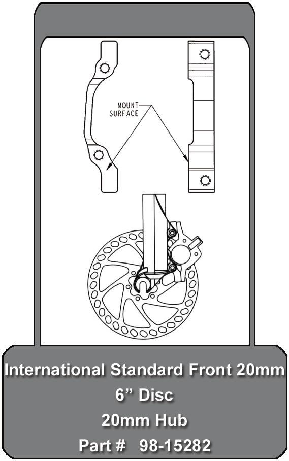
4 Installation 4 The following procedures cover the installation of Hayes Disc Brakes purchased as an aftermarket item. If you have purchased a bike new - with Hayes Disc Brakes already installed - you will not immediately require all of the procedures. When you need to install any of the disc brake components, a qualified technician with the proper tools should do that installation work. Improper installation could cause severe or fatal injuries. A. Tools Required Torx T25 driver Open-end wrenches; 6mm, 8mm, 10mm Scissors or cable cutters Small Phillips screwdriver Torque wrench Small flathead screwdriver Allen drivers: 2.0mm and 5mm B. Mounting the Disc to the Hub Note: Mounting the brake disc to the wheel is a simple matter, but one that requires care. If the wheel has to be rebuilt, have it done by a qualified technician using a 3 cross spoke pattern. We recommend the use of steel, quick release skewers only. 1. Clean the disc and the hub-mounting surface with isopropyl alcohol (not disc brake cleaners). 2. Place the disc on the hub-mounting surface. Be sure that the arrow on the disc is pointing in the same direction of the forward wheel rotation. 3. Using a Torx T25 driver, install, tighten, and torque the disc screws to 55 in-lbs (6.2 Nm), in a star pattern sequence. Tightening the Disc 4. Check and re-torque the disc screws after 12 hours Screws Warning: Do not touch the disc immediately after use - it will be hot. C. Mounting the Caliper to the Frame or Fork 1. Remove the wheel(s). 2. For some installations it will be necessary to mount an adapter to accept the Hayes Disc Brake caliper. Mount the fork adapter to the fork using (2) M6 x mm long mount bolts. Torque the bolts to 110 in-lbs (12.43Nm). 3. Mount the caliper to the frame or fork adapter using (2) M6 x mm long mount bolts and (2) mount washers. Snug the bolts, but leave them loose enough so that the caliper will move on its slots. 4. Re-install the front wheel. 5. Squeeze and hold the brake lever. While holding the brake lever, shake the caliper to position it in its natural centered position over the disc. While still squeezing the lever, tighten the mounting bolts. Warning: Do not adjust the caliper while the caliper is hot Warning: Do not adjust the caliper while the wheel is spinning.

5 5 6. Release the lever, spin the wheel. Check that it spins freely and that the gaps, between the pad and the disc, are equal. If the gaps are unequal, or there is drag, readjust the caliper position by loosening the mounting bolts and adjusting the caliper as needed. Hint: A white piece of paper can be used as a background to help sight down the disc looking for equal clearance between the pads and the disc. 7. When the gaps are equal and wheel spins freely (without drag), torque the mounting bolts to 110 in-lbs (12.43 Nm). 8. Repeat the procedure for the other wheel. C. Hose Removal and Assembly The hose assembly procedure is different for the different brake models and design variations. Pay close attention to which procedure applies for your Hayes disc brake system. Hose Removal HFX-9, HFX-9 HD, HFX-Mag, and HFX-Mag Plus Master Cylinder and G1 (Generation 1) Caliper Hose Removal To take the hose off of the master cylinder end, slide the hose support down the hose. Remove the hose nut by loosening the nut and sliding it all the way down the hose. 1. Slide the hose off the end of the master cylinder. There will be some residual fluid in the hose and master cylinder. Be careful to avoid spilling that fluid. Caution: For the HFX-Mag and HFX-Mag Plus, pull the hose off straight off. Not doing so may result in a broken cartridge tip. 2. A new compression bushing will be needed each time the hose is re-installed. Remove the old compression bushing by cutting the hose next to the compression bushing. The cut needs to clean with no fraying ends. Note: Check the hose length for adequate travel. If too short, replace hose. G2 Caliper Hose Removal (Generation 2) 1. To take the hose off the caliper end, loosen the hose connection with a 10mm open-end wrench. 2. Remove the hose connection completely from the caliper. Be sure that the hose connection seal is not lost. Note: The end of the G2 caliper hose is a permanent crimp. Therefore the connection cannot be trimmed to size or repaired. Shortening of the hose must be done at the master cylinder end. If the caliper hose connection is damaged, the hose must be completely replaced with a new hose with a permanent crimp attached. Hose Assembly G2 Caliper Hose Assembly (Generation 2) 1. Locate end of hose with the permanent crimp attached. 2. Place the hose connection seal over the threaded end. Make sure the seal is not twisted. 3. Install hose connection to the G2 caliper. 4. Using a 10mm open-end wrench, torque the hose connection to 60 +/- 5 in/lb. G2 Caliper Hose Assembly
 caliper. The end must be clean and perpendicular to the hose itself. 3.")


6 G1 Caliper Hose Assembly (Generation 1) 1. Locate the end of hose with permanent crimp attached. 2. Cut the permanent crimp off of the hose. This permanent crimp is not needed with the Generation 1 (G1) caliper. The end must be clean and perpendicular to the hose itself. 3. Slide the G1 caliper hose nut and compression bushing over the hose. Always use a new compression bushing. Note: The G1 caliper hose nut has internal threads and G1 Caliper Hose Assembly the compression bushing is a silver color. 4. Slide the hose over the barbed end on the caliper banjo and install the hose nut. 5. Using a 10mm open-end wrench, torque the hose nut to 40 in-lb plus one full rotation. HFX 9, HFX-9 HD Master Cylinder Hose Assembly 1. Locate the end of hose without the permanent crimp attached. 2. Cut the hose to the desired length with good scissors or cable cutters. The cut end must be clean and perpendicular to the hose itself. 3. Slide the HFX-9 nose cone onto the hose. Note: The HFX-9 nose cone is the smaller of the two included. HFX-9 Hose Assembly 4. Slide the HFX-9 hose nut and compression bushing over the hose. Always use a new compression bushing. Note: The HFX-9 hose nut has external threads and the compression bushing is a gold color. 5. Push the longer end of the HFX-9 barbed hose insert into end of hose. Be sure it is inserted flush with the end of hose. Always use a new hose insert. 6. Place the hose inset o-ring over the exposed end of the hose insert. 7. Slide hose, with hose inset and o-ring, into the HFX-9 master cylinder and install the hose nut. Be sure that the hose is inserted completely into the master cylinder end. Be sure the hose remains inserted while tightening. 8. Using a 8mm open-end wrench, torque the hose nut to 60 +/- 5 in/lb. 9. Bleed the system. HFX-Mag/HFX -Mag Plus Master Cylinder Hose Assembly 1. Locate the end of hose without the permanent crimp attached. 2. Cut the hose to the desired length with good scissors or cable cutters. The cut end must be clean and perpendicular to the hose itself. 3. Slide HFX-Mag nose cone onto the hose. Note: The HFX-Mag nose cone is the larger of the two. 4. Slide the HFX-Mag hose nut and compression bushing over the hose. Always use a new compression bushing. HFX-Mag Hose Assembly Note: The HFX-Mag hose nut has internal threads and the compression bushing is a silver color. 5. Slide the hose over the barbed end on the master cylinder cartridge and install the hose nut. 6. Using a 10mm open-end wrench, torque the hose nut to 40 in-lb plus one full rotation. 7. Bleed the system. 6
7 A. Bleed Kit Assembly: 1. Screw the cap onto the end of the bottle. 2. Cut a 2" section of hose. 3. Push the short section of hose over the cap until it slides past the ridge on the cap. 4. Push the long section of hose into the master cylinder bleed fitting Note: There are two fittings with the kit. The clear, cone shaped fitting is to be used with the HFX Mag and HFX Mag Plus. The silver aluminum fitting is to be used with the HFX-9. B. Bleeding the System Air entrapped in the hydraulic system of the disc brakes can decrease performance of the system and should be removed by bleeding the system and replenishing the system with new brake fluid. The system is filled by pumping fluid from the lowest point (at the caliper), through the system, to the highest point, the bleeder on the master cylinder. Note: The bleed instructions include steps for the HFX Mag and HFX-9 brake systems. Read them carefully, since instructions vary for the type of brake system you have. Caution: Use only new DOT 4 or DOT 3 brake fluid from a closed, sealed container. Use of any other fluid can cause the rubber parts to degrade and cause the brake to fail. Caution: DOT 4 or DOT 3 brake fluid will strip paint. Use extreme caution to avoid getting DOT 4 or DOT 3 brake fluid on paint. If DOT 4 or DOT 3 brake fluid comes in contact with paint, wipe it off immediately and rinse with isopropyl alcohol. Warning: If you get any brake fluid on the brake pads, discard them and replace with new pads. If you get any brake fluid on the disc, clean it thoroughly with isopropyl alcohol. Warning: DOT 4 or DOT 3 brake fluid can be an irritant when it comes into contact with human tissue. For skin contact, brake fluid should be washed off in flowing water. For eye contact, the eye area should be irrigated with flowing water immediately and continuously for 15 minutes. Consult with medical personnel. If effects occur from inhaling brake fluid fumes, move to an area with fresh air. Consult a physician. If brake fluid is ingested, induce vomiting and consult medical personnel. Used brake fluid should be disposed of according to local laws. 1. Remove the wheel. 2. Remove the brake pads so that any spilled fluid does not contaminate the pads. Using the tab in the center of the pad backing plate, pull each pad toward the center of the caliper and out. There is a spring that holds the pad in place. That spring snaps on to the post at the center of the piston. 3. Push the caliper pistons all the way into their bores using the box end of a 10 mm end wrench. Caution: Don t push on the post in the center of the piston because that will bend the post. Walk the piston back and forth until the piston is all the way back in the bore. Do the same thing on the other side. Position the bike in a stand so that the brake caliper bleeder screw is perpendicular to the ground, and so that the bleed screw (HFX-Mag) or reservoir plug (HFX-9) on the master cylinder is the highest point on the brake system. This can be done by loosening the master cylinder clamp screws and rotating the master cylinder upright on the handlebars 7

 or reservoir plug (HFX-9) and press the fitting with the hose into the hole.")


8 Note: For the HFX-Mag, the bike should be in the stand with the front wheel higher than the rear at a 45-degree angle and the lever should point up at a 45-degree angle. For a left hand lever, turn the handlebars all the way to the right, and for the right hand lever, turn the handlebars all the way to the left. Note: For the HFX-9 the bike should remain horizontal to the ground, and the lever should remain parallel to the ground. HFX-Mag HFX-9 5. Remove the master cylinder bleed screw (HFX- Mag) or reservoir plug (HFX-9) and press the fitting with the hose into the hole. The other end of the hose should go into a cup or bottle to catch the excess fluid. Be sure not to submerge the end of the hose in fluid. Hint: Taping a spoke to a bottle and bending it to hook around the handlebars makes a convenient hanger. Note: The HFX-Mag master cylinder bleed fitting is a Phillips head screw and requires the use of the clear cone shape bleed fitting included in the bleed kit. Note: The HFX-9 master cylinder reservoir plug is a plastic cap, which needs to be removed with your fingers or a small flat head screwdriver. DO NOT remove the two T-10 Torx bolts holding the cap on. The HFX-9 requires the use of the silver aluminum bleed fitting included in the bleed kit. 6. Completely remove the caliper bleeder s rubber cap. 7. Fill the plastic filler bottle with fresh DOT 3 or DOT 4 brake fluid. 8. Close the caliper bleeder. 9. Place the hose from the fluid bottle onto the caliper bleeder. Pump the fluid bottle until there is no air in the hose. 10. Open the caliper bleeder 1/4 turn. 11. Squeeze the fluid bottle firmly forcing fluid into the caliper for a count of five. Stop squeezing - until the bottle returns to its natural shape. When the squeeze is released, Bleed Fittings Filler Bottle Attachment air should be drawn out of the caliper. Continue alternately squeezing the fluid bottle, for a count of five, and releasing until no air bubbles come out of the caliper. 12. After all the air is out of the caliper; squeeze the bottle until fluid comes out at master cylinder with no air bubbles. 13. While squeezing the bottle, quickly stroke the lever to the handlebars, and release. Repeat this until no more air bubbles come out of the master cylinder. 14. With the bottle still being squeezed, close the caliper bleeder. Torque should be only to seal the bleeder. Caution: Do not over torque! Then release and remove the bottle and filler hose. 8


9 Maintenance Maintenance Procedures Due to wear, contamination, or damage, the brake pads will, on occasion have to be replaced. A. Brake Pad Change 1. Remove the wheel. 2. Using the tab in the center of the pad backing plate, pull the pad toward the center of the caliper and out. There is a spring that holds them in place. That spring snaps on to the post at the center of the piston. 3. Repeat the steps for the other side pad. To replace the pads Using the boxed end of a 10mm wrench, push the caliper pistons back until they bottom. This will give you more room to fit in the new pads. Take care not to push on the aluminum post in the center of the piston. Caution: Don t push on the post in the center of the piston because that will bend the post. Walk the piston back and forth until the piston is all the way back in the bore. Do the same thing on the other side. Note: There are two different brake pads, an inner and outer or a right and a left. On the outer pad the tab is offset. On the inner pad the tab is in the center. 5. Put the outer pad in first. Use the tab in the center of the pad backing plate to push the new pads into place. Angle the pad slightly so the post is towards the center of the caliper and push the pad until it snaps into place. Check that the pad is locked into position. 6. Now repeat the procedure for the outer pad. 7. Install the wheel. Removing Brake Pads Pushing the Pistons Back Outer and Inner Brake Pads 9
 Pumped Out If the brake lever is stroked without the disc between the pads (and this is possible when brake pads are being changed), the self-adjusting feature will allow the pads to push")
10 Maintenance con t B. Piston(s) Pumped Out If the brake lever is stroked without the disc between the pads (and this is possible when brake pads are being changed), the self-adjusting feature will allow the pads to push out. The caliper pistons will be pumped out of their bore. This will cause excessive drag on the disc when the wheel and disc are reinstalled, or even make it impossible to install the wheel and disc. To fix this problem 1. Remove the brake pads from the caliper if they are not already removed. 2. Hint: If the pads are pushed together tight, slide a series of thin cards between the pads to initiate a gap and enlarge the gap until it is large enough to pull the pads out. If you are going to replace the pads anyway, you can use a screwdriver instead of the cards to create the gap. But the screwdriver will break the friction material apart and the pads will definitely have to be discarded. 3. With the pads removed, push the pistons all the way back into the caliper using the box end of a 10 mm end wrench. Caution: Don t push on the post in the center of the piston because that will bend the post. Walk the piston back and forth until the piston is all the way back in the bore. Do the same thing on the other side. 4. When the pistons are back into their bores, replace the pads putting them in at a slight angle so that the spring catches the post on the piston. C. Cleaning and Care The brake disc and pads should only be cleaned with isopropyl alcohol (not disc brake cleaner). Service This service segment is designed to assist the reader with the service and repair of Hayes Disc Brakes. Read and be familiar with the instructions. The user should have a good knowledge of mechanical procedures, and should be equipped with proper tools and equipment. Incorrect service or repair may reduce braking performance, and could lead to a safety or personal hazard situation. If you have any doubts about the procedure described, due to limited experience or because of the lack of necessary tools and equipment, contact your local dealer or mechanic. Remember, always Think Safety. 10
11 Service con t A. Troubleshooting The following chart provides a quick reference as to the possible cause and the normal corrective action for the most common problems. Problem Possible Cause Corrective Action Lever goes Bad Bleed Re-bleed to the handlebar Bad Cartridge Replace Cartridge and re-bleed System Leak Look for leak and see Fluid loss below Disc rubbing on Caliper not centered Re-center the caliper the pads over disc Inadequate clearance Push pistons back Bent Disc Replace Disc Spongy Lever Bad Bleed Re-bleed No braking power Dirty disc Clean disc with alcohol Contaminated pads Replace pads Pads fall out Bent or broken piston Replace piston post Bent or missing spring Replace pads Fluid loss Banjo leaking Replace banjo O-rings Hose leaking Tighten hose nut Replace hose Replace compression bushing Master cylinder bleeder Replace bleeder screw & O-ring Master cylinder cartridge Replace bleeder Rebuild master cylinder assembly B. Tools Box/Open end wrenches: 6mm, 8mm, 10mm, & 13mm, Allen wrenches: 2.0mm, 4mm, & 5mm Torque wrench: With 4mm, & 5mm bits, & Torx T25 Driver Isopropyl alcohol Hayes bleed kit Bottle to catch drained fluid Fresh DOT 4 or DOT 3 brake fluid Small Phillips and flat screwdriver Approved O-ring Lubricant Hammer and Drift Punch Warning: Always wear safety glasses when servicing the brake system or other components of your bike. 11
12 Torque Chart 12 Item Torque Disc Screws 50 +/-5 in-lbs (5.65 +/-.55 Nm) Handlebar Master Cylinder Clamp Screw HFX-Mag, HFX-Mag Plus : in-lbs ( Nm) HFX-9 : in-lbs. ( Nm) Master Cylinder Jam Nut 50 in-lbs +/- 5 in-lbs (5.65 +/-.55 Nm) Caliper Bleeder 2.0 in-lbs (.23 Nm) (Torque to seal. Do not overtorque) Caliper Bridge Bolts 110 +/- 10 in-lbs (12.43+/- 1.1 Nm) Caliper Mount Bolts 110 +/- 10 in-lbs. ( /- 1.1 Nm) Hose Connection Master Cylinder HFX-Mag, HFX-Mag Plus 40 in-lbs (4.52 Nm) + 1 full rotation HFX /- 5 in-lbs (6.78 +/-.55Nm) Caliper : G1 : 40 in.-lbs. (4.52 Nm) + 1 full rotation 2003 G2 60 +/- 5 in-lbs (6.78 +/-.55Nm) Warranty Any Hayes Disc Brake found by the factory to be defective in materials and/or workmanship within two years from the date of purchase will be repaired or replaced at the option of the manufacturer, free of charge, when received at the factory with proof of purchase, freight prepaid. This includes assembly costs (for instance by the dealer), which shall not be covered by Hayes Disc Brake. This warranty does not cover breakage, bending, or damage that may result from crashes or falls. This warranty does not cover any defects or damage caused by alterations or modifications of new Hayes disc Brakes or parts or by normal wear, accidents, improper maintenance, damages caused by the use of parts of different manufacturers, improper use or abuse of the product, or failure to follow instructions contained in an instruction manual for Hayes Disc Brake. Any modifications made by the user will render the warranty null and void. The cost of normal maintenance or replacement of service items, which are not defective, shall be paid for by the original purchaser. This warranty is expressly in lieu of all other warranties, and any implied are limited in duration to the same duration as the expressed warranty herein. Hayes Disc Brake shall not be liable for any incidental or consequential damages. If for any reason warranty work is necessary, return the brake to the place of purchase. In the USA, contact Hayes Disc Brake for a return authorization number (RA #) at (888) At that time, instructions for repair, return, or replacement shall be given. Customers in countries other than USA should contact their dealer or local Hayes Disc Brake distributor.

13 Disc Components

14 Hose Components 14 HFX-9 HFX-Mag

15 Caliper Components 15
16 Master Cylinder Components 39 HFX-Mag

17 17 Master Cylinder Components 42 HFX
18 Mount Brackets 18
19 19
20 20
Installation & Set-Up Instructions
 Installation & Set-Up Instructions Hayes Performance Systems 5800 W. Donges Bay Rd. Mequon, WI 53092 Tel: 888.686.3472 Email: techsupport@hayesbicycle.com Web: www.hayescomponents.com Hayes Components
Service & Bleed Guide
 Service & Bleed Guide Hayes Performance Systems 5800 W. Donges Bay Rd. Mequon, WI 53092 Tel: 888.686.3472 Email: techsupport@hayesbicycle.com Web: www.hayescomponents.com Hayes Components Europe Dirnismaning
HYLEX for HYDRAULIC DISC BRAKE SYSTEM. Rev. A Copyright Devecmber 2012 Manufactured in Taiwan
 HYLEX for HYDRAULIC DISC BRAKE SYSTEM Rev. A070213 Copyright Devecmber 2012 Manufactured in Taiwan CONTENTS TRP HYLEX OWNER S MANUAL I. INTRODUCTION a. Welcome b. About Your HYLEX Brakes c. Break In Period
DISC BRAKE/DUAL MASTER CYLINDER CONVERSION. Tools, Equipment and Supplies Needed:
 Please take the time to read the enclosed instructions carefully. If you have any questions, call our Product Assistance personnel for clarification. It is important to note that these instructions contain
Giant Hydraulic Disc Brake System
 Giant Hydraulic Disc Brake System INSTALLATION INSTRUCTI IMPORTANT NOTICE Contact the place of purchase or Authorized Giant Retailer for information on detail of installation and maintenance. Read this
Installation and Setup Guide
 Installation and Setup Guide Proudly made by ELITE Installation and Setup Guide PREFACE Thank you for purchasing our disk brake system. This manual contains important information regarding our products'
 .1..2..3..4..5..6..7..8..9..10. MANITOU SUSPENSION FORKS CONGRATULATIONS ON CHOOSING A 2003 MANITOU SIX FORK. This Manitou SIX fork is fully assembled and ready to be installed onto your bicycle. It comes
Tools, Equipment and Supplies Needed:
 153-162 DISC BRAKE/DUAL MASTER CYLINDER CONVERSION Please take the time to read the enclosed instructions carefully. If you have any questions, call our Product Assistance personnel for clarifi cation.
Disc Brake System ( For Cross-Country)
") Technical Service Instructions General Safety Information Disc Brake System ( For Cross-Country) SI-8C60F t WARNING Please use extra caution to keep your fingers away from the rotating disc brake rotor
Technical Service Instructions General Safety Information Disc Brake System ( For Cross-Country) SI-8C60F t WARNING Please use extra caution to keep your fingers away from the rotating disc brake rotor
This chapter covers the location and servicing of the front brake components for the KYMCO MXU 700i and MXU 500i models.
 KYMCO MXU 500i/700i Repair Manual Brake System 9.Brake System This chapter covers the location and servicing of the front brake components for the KYMCO MXU 700i and MXU 500i models. 1.Brake Discs... 9-3
w w w. h d o n l i n e s h o p. d e MODULAR DIAMONDBACK BRAKE LINE KITS GENERAL -J04284 REV Kit Number Models Tools and Supplies Required
 -J08 REV. 007-07-6 GENERAL MODULAR DIAMONDBACK BRAKE LINE KITS Table. Upper Brake Line s (Banjo Angle 0 - Straight) 7-07 77-07 79-07 8-07 87-07 9-07 8-07 8 inch 9 inch 0 inch inch inch inch inch 96-07
Disc brake Installation & Service Manual Mono6ti Mono M4 Mono Mini. Hope Technology HOPE
 Disc brake Installation & Service Manual Mono6ti Mono M4 Mono Mini HOPE Hope Technology UK Head Office and Manufacturing Hope Mill, Skipton Road Barnoldswick Lancashire BB18 6EN United Kingdom Tel : +
WARRANTY INFORMATION AMERICAN MADE MANITOU SUSPENSION
 AMERICAN MADE MANITOU SUSPENSION CONGRATULATIONS ON CHOOSING THE LATEST IN SUSPENSION TECHNOLOGY AVAILABLE, A 2003 MANITOU DORADO FORK BUILT IN THE USA. This DORADO fork is fully assembled and is ready
Hayes Performance Systems 5800 W. Donges Bay Rd. Mequon, WI Tel: Web:
 Hayes Performance Systems 5800 W. Donges Bay Rd. Mequon, WI 53092 Tel: 888.686.3472 Email: techsupport@hayesbicycle.com Web: www.hayescomponents.com Hayes Components Europe Dirnismaning 20 a 85748 Garching
BRAKE SYSTEM Return To Main Table of Contents
 BRAKE SYSTEM Return To Main Table of Contents GENERAL... 2 BRAKE PEDAL... 10 MASTER CYLINDER... 13 BRAKE BOOSTER... 16 BRAKE LINE... 18 PROPORTIONING VALVE... 19 FRONT DISC BRAKE... 20 REAR DRUM BRAKE...
Heavy Duty Engine Cranes
 Heavy Duty Engine Cranes Operating Instructions & Parts Manual Model Number Atd-7484 Atd-7485 (Foldable Legs) Capacity 2 Ton 2 Ton Model Atd-7484 Model Atd-7485 Atd Tools Inc. 160 Enterprise Drive, Wentzville,
(english) technical manual. part#
 technical manual. part#") 008 (english) technical manual part# 95-5015-011-000 SRAM original Parts Caution: The SRAM Warranty policy does not cover damages caused by the use of non-sram parts. Use only SRAM parts with SRAM components.
008 (english) technical manual part# 95-5015-011-000 SRAM original Parts Caution: The SRAM Warranty policy does not cover damages caused by the use of non-sram parts. Use only SRAM parts with SRAM components.
INSTALLATION GUIDE. RMS510, 511, 512, 513, 511MC 510-OR, 512-OR Manual Revision:
 REKLUSE MOTOR SPORTS z-start Dual-Actuated Brake Kit INSTALLATION GUIDE RMS510, 511, 512, 513, 511MC 510-OR, 512-OR 196-210 Manual Revision: 051309 2002-2009 Rekluse Motor Sports Rekluse Motor Sports,
INSTALLATION INSTRUCTIONS
 INSTALLATION INSTRUCTIONS FX4 ELITE REAR DISC CONVERSION KITS WITH INTERNAL PARKING BRAKE A110-14, A111-25, A111-29 for FORD 8" & 9" REAR ENDS Thank you for choosing STAINLESS STEEL BRAKES CORPORATION
Brake Upgrade Kit Fitting Instructions Bonneville America
 WARNING: Always have Triumph approved parts, accessories and conversions fitted by a trained technician of an authorised Triumph Dealer. The fitment of parts, accessories and conversions by a technician
w w w. h d o n l i n e s h o p. d e CHROME FRONT BRAKE MASTER CYLINDER KIT GENERAL INSTALLATION -J03735 REV Kit Number Models
 -J05 REV. 005-06- GENERAL Kit Number 58-D, 58-D Models CHROME FRONT BRAKE MASTER CYLINDER KIT These Chrome Master Cylinder Kits are designed to replace the original equipment front brake master cylinder
Hayes Performance Systems 5800 W. Donges Bay Rd. Mequon, WI Tel: Web:
 Hayes Performance Systems 5800 W. Donges Bay Rd. Mequon, WI 53092 Tel: 888.686.3472 Email: techsupport@hayesbicycle.com Web: www.hayescomponents.com Hayes Components Europe Dirnismaning 20 a 85748 Garching
Air Actuated Hydraulic Bottle Jacks
 Air Actuated Hydraulic Bottle Jacks Operating Instructions & Parts Manual Model Number Atd-7412 Atd-7420 Capacity 12 Ton 20 Ton Atd Tools Inc. 160 Enterprise Drive, Wentzville MO 63385 Printed in China
Operating Instructions & Parts Manual. Fuel Tank Adapter
 Operating Instructions & Parts Manual Fuel Tank Adapter Model Number 40080 Capacity 80 lb.! This is the safety alert symbol. It is used to alert you to potential personal injury hazards. Obey all safety
Hayes Performance Systems 5800 W. Donges Bay Rd. Mequon, WI Tel: Web:
 Hayes Performance Systems 5800 W. Donges Bay Rd. Mequon, WI 53092 Tel: 888.686.3472 Email: techsupport@hayesbicycle.com Web: www.hayescomponents.com Hayes Components Europe Dirnismaning 20 a 85748 Garching
INSTALLATION INSTRUCTIONS
 INSTALLATION INSTRUCTIONS REAR DISC BRAKE CONVERSION KITS A112, A112-1 & A112-93 1979-93 FORD MUSTANG with 7.5" & 8.8" AXLES Thank you for choosing STAINLESS STEEL BRAKES CORPORATION for your braking needs.
Installation Instructions and Service Manual
 Installation Instructions and Service Manual Model 80 Actuator* for Trailer Brakes 8,00 lbs Capacity Drum Brake Ready Disc Brake Ready US Patents: 6,37,2 and 8,342,9 *Model 80 - Manufactured after March
Installation Manual TWM Performance Short Shifter Cobalt SS/SC, SS/TC, HHR SS, Ion Redline and Saab 9-3
 Page 1 Installation Manual TWM Performance Short Shifter Cobalt SS/SC, SS/TC, HHR SS, Ion Redline and Saab 9-3 Please Note: It is preferable to park on a flat surface, as you will have to engage and disengage
Front Brake Caliper. Item Standard Service Limit /.051mm Measurements Brake Disc Runout /.50mm. Rear Brake Caliper
 CHAPTER 9 BRAKES Specifications/Torques... 9.1 Brake System Service Notes... 9.2 Brake Pad Kits... 9.2 Brake Noise Troubleshooting... 9.3 Hydraulic Brake System Operation... 9.4 Fluid Replacement/Bleeding
Manual Operated Floor Jack
 Manual Operated Floor Jack OPERATING INSTRUCTIONS Note: There may be some slight differences in the appearance of the various manually-operated floor jacks, however the instructions in this manual apply
Heavy Duty Bottle Jacks
 Heavy Duty Bottle Jacks Models: 10300 & 10500 10300 10500! This is the safety alert symbol. It is used to alert you to potential personal injury hazards. Obey all safety messages that follow this symbol
Low Profile Service Jack
 Low Profile Service Jack Operating Instructions & Parts Manual Model Number JSA200LCX Capacity 2 Ton MAC TOOLS INC. 2005 505 N. Cleveland Ave. Suite 200 Westerville, OH 43082 Printed in PRC Save these
RHINO SUSPENSION SYSTEM INSTALLATION INSTRUCTIONS
 PARTS INCLUDED: 2 FRONT UPPER A-ARMS 2 FRONT LOWER A-ARMS 2 UNI-BALL JOINTS 2 UNI-BALL JOINT STUDS 2 UNI-BALL JOINT CAPS 2 RETAINING RINGS 1 FRONT SHOCK ASSEM. 2 DELRON STEERING STOPS 2 SHOCK MOUNT SPACERS
12. FRONT WHEEL/FRONT BRAKE/
 12 4.5kgm 0.9kg-m 4.5kg-m 12-0 SERVICE INFORMATION... 12-1 HYDRAULIC BRAKE... 12-10 TROUBLESHOOTING... 12-2 FRONT SHOCK ABSORBER... 12-16 FRONT WHEEL... 12-3 STEERING HANDLEBAR... 12-19 FRONT BRAKE...
RST fork should not be used if any parts appear to be or are damaged. Contact your local dealer or distributor for replacement parts.
 Proper care and maintenance of your RST product is necessary for longevity and optimum performance. Failing to perform normal maintenance will greatly decrease the performance of the product and may lead
INSTALLATION INSTRUCTIONS
 INSTALLATION INSTRUCTIONS DISC BRAKE CONVERSION KITS A120-4 & A120-5 1964-1/2-66 Ford & Mercury Thank you for choosing STAINLESS STEEL BRAKES CORPORATION for your braking needs. Pleases take the time to
Fitting Instructions for CODA Expert Disc Brakes
 Fitting Instructions for CODA Expert Disc Brakes Congratulations and thanks for your purchase of the CODA Expert Disc Brake system. The CODA Expert Disc Brake is a fully hydraulic closed system which provides
INSTALLATION INSTRUCTIONS
 INSTALLATION INSTRUCTIONS REAR DISC CONVERSION KIT A128-4 1997-2004 JEEP WRANGLER (TJ) WITH DANA 44 AXLES (non-abs) Thank you for choosing STAINLESS STEEL BRAKES for your braking needs. Pleases take the
63-82 CORVETTE IMPALA KIT INSTRUCTIONS
 63-82 CORVETTE 61-69 IMPALA KIT INSTRUCTIONS RACE, STREET, 2 PISTON AND 4 PISTON FRONT KITS ARE ALL COVERED IN THESE INSTRUCTIONAL SHEETS. 1 AEROSPACE COMPONENTS 727.347.9915 Preparing the spindle: You
Installation Instructions
 Preparing your vehicle to install your brake system upgrade 1. Rack the vehicle. 2. If you don t have a rack, then you must take extra safety precautions. 3. Choose a firmly packed and level ground to
Telescopic Transmission Jacks
 Telescopic Transmission Jacks Operating Instructions & Parts Manual Model Number BH7051 BH7055 (Air/Manual) Capacity 1/2 Ton 1/2 Ton SFA Companies 2006 10939 N. Pomona Ave. Kansas City, MO 64153 816-891-6390
82-92 CAMARO, FIREBIRD RACE/STREET 4-PISTON FRONT BRAKE KIT INSTRUCTIONS
 M- F 8:00a.m.-8:00p.m. EST. 82-92 CAMARO, FIREBIRD RACE/STREET 4-PISTON FRONT BRAKE KIT INSTRUCTIONS YOU WILL NEED TO MODIFY YOUR SPINDLE. NOTE: You will need to cut the factory caliper mounting ears off
Installation Instructions and Service Manual
 Installation Instructions and Service Manual Model 66 Actuator* for Trailer Brakes 6600 lbs Capacity Part #47210/86167 - Drum Brake Ready Part #47211/86165 - Disc Brake Ready *US Patent No. 6,375,211 MODEL
INSTALLATION INSTRUCTIONS
 INSTALLATION INSTRUCTIONS HeliBars Tour Performance Adjustable Handlebar Bridge 2006-2013 Yamaha FJR1300 US & European P/N: HR09079 IMPORTANT: PLEASE GIVE CUSTOMER ENCLOSED INFORMATION! Thank you for your
Hydraulic Clutch Jack
 Hydraulic Clutch Jack Operating Instructions & Parts Manual Model Number Atd-7404 Capacity 500 Lb. Atd Tools Inc. 160 Enterprise Drive, Wentzville MO 63385 Printed in China ATD7404-M0 05/07 Save these
Hydraulic Transmission Jacks
 Hydraulic Transmission Jacks Operating Instructions & Parts Manual Model Number Atd-7435 Atd-7436 Atd-7437 Capacity 1100 Lb. 2000 Lb. 3000 Lb. Model Atd-7435 Model Atd-7436 Model Atd-7437 Atd Tools Inc.
INSTALLATION INSTRUCTIONS
 INSTALLATION INSTRUCTIONS FRONT BIG BRAKE CONVERSION KIT A112-5 1987-93 FORD MUSTANG Thank you for choosing STAINLESS STEEL BRAKES CORPORATION for your braking needs. Pleases take the time to read and
INSTALLATION GUIDE. RMS500, RMS501, RMS502, RMS503, RMS506, RMS507, RMS508, RMS509, -OR Manual Revision:
 REKLUSE MOTOR SPORTS z-start Brake Kit INSTALLATION GUIDE RMS500, RMS501, RMS502, RMS503, RMS506, RMS507, RMS508, RMS509, -OR 196-200 Manual Revision: 051309 2009 Rekluse Motor Sports Rekluse Motor Sports,
INSTALLATION INSTRUCTIONS
 INSTALLATION INSTRUCTIONS REAR DISC BRAKE CONVERSION KIT A125-3 1965-72 GM A-BODY 10 & 12 BOLT AXLES Thank you for choosing STAINLESS STEEL BRAKES CORPORATION for your braking needs. Pleases take the time
SPECIFICATIONS CONTENTS:
 Model 3052 1,100 Lbs 2 Stage Transmission Jack INSTRUCTION MANUAL CONTENTS: Page 1 Specifications Page 2 Warning Information Page 3 Assembly Page 4 Operating Instructions Page 4 Preventative Maintenance
SPECIFICATIONS CONTENTS:
 Model 3052A 1,100 Lbs Air Assist 2 Stage Transmission Jack INSTRUCTION MANUAL CONTENTS: Page 1 Specifications Page 2 Warning Information Page 3 Assembly Page 4 Operating Instructions Page 4 Preventative
Service Jacks. Operating Instructions & Parts Manual. Model Number. Capacity 4 Ton 4 Ton Air/ Manual 10 Ton 10 Ton Air/ Manual HW93657/ HW93660
 Service Jacks Operating Instructions & Parts Manual Model Number HW93657 HW93667 HW93660 HW93662 Capacity 4 Ton 4 Ton Air/ Manual 10 Ton 10 Ton Air/ Manual Made in North America HW93657/ HW93660 HW93667/
w w w. h d o n l i n e s h o p. d e ROAD KING FAT HANDLEBAR KIT GENERAL PREPARATION - ALL MODELS -J02375 REV Kit Number Models ABS Models
 -J02375 REV. 2008--9 GENERAL Kit Number 56675-05 Models For model fitment information, see the P&A Retail Catalog or the Parts and Accessories section of www.harley-davidson.com (English only). ABS Models
INSTALLATION INSTRUCTIONS
 INSTALLATION INSTRUCTIONS REAR DISC BRAKE CONVERSION KIT A126-3 1988-98 CHEVY K1500 4WD 10" DRUMS Thank you for choosing STAINLESS STEEL BRAKES CORPORATION for your braking needs. Pleases take the time
Juicy Seven, Juicy Carbon & Juicy Five. Installation and Setup Guide
 Juicy Seven, Juicy Carbon & Juicy Five Installation and Setup Guide PLEASE READ THE SAFETY AND WARRANTY INFORMATION INSIDE 955-310588-000 Rev. C SRAM Corporation, 2006 Juicy TM Installation & Setup Guide
SCION tc BIG BRAKE KIT Section I - Installation Preparation
 SCION tc 2005- BIG BRAKE KIT Section I - Installation Preparation Part Number: PTR09-21080 Kit Contents Item # Quantity Reqd. Description 1 1 Brake Rotor, LH Front 2 1 Brake Rotor, RH Front 3 1 Brake Caliper
Low Profile Service Jack Jack Stand Combo
 Low Profile Service Jack Jack Stand Combo Jack Stands Low Profile Service Jack U.S. Patent No. 6,199,379! This is the safety alert symbol. It is used to alert you to potential personal injury hazards.
INSTALLATION & USER S GUIDE
 REKLUSE MOTOR SPORTS The Rekluse Left Hand Rear Brake Kit INSTALLATION TIPS INSTALLATION & USER S GUIDE Doc ID: 196-5301 Doc Rev: 031016 Before continuing, we recommend watching the Brake Kit Installation
INSTALLATION INSTRUCTIONS
 INSTALLATION INSTRUCTIONS PERFORMANCE AT THE WHEELS KITS W156-6 & W156-7 1965-74 MOPAR B & E BODY Thank you for choosing STAINLESS STEEL BRAKES CORPORATION for your braking needs. Pleases take the time
INSTALLATION INSTRUCTIONS
 INSTALLATION INSTRUCTIONS REAR CONVERSION KIT A111-2 (FORD 8" & 9" SMALL BEARING) & REAR CONVERSION KIT A111-3 (FORD 9 TORINO) Thank you for choosing STAINLESS STEEL BRAKES CORPORATION for your braking
Hayes Performance Systems 5800 W. Donges Bay Rd. Mequon, WI Tel: Web:
 Hayes Performance Systems 5800 W. Donges Bay Rd. Mequon, WI 53092 Tel: 888.686.3472 Email: techsupport@hayesbicycle.com Web: www.hayescomponents.com Hayes Components Europe Dirnismaning 20 a 85748 Garching
INSTALLATION INSTRUCTIONS
 INSTALLATION INSTRUCTIONS PERFORMANCE AT THE WHEELS KIT W155-5 CHRYSLER 8 3 /4" & 9 3 /4" REAR AXLES Thank you for choosing STAINLESS STEEL BRAKES CORPORATION for your braking needs. Please take the time
Final Assembly Instructions Portside Cruiser
 Final Assembly Instructions Portside Cruiser Thank you for buying your new bicycle from L.L.Bean. Read these instructions carefully before beginning the final assembly. Prior to shipping, our expert cycling
Hayes Performance Systems 5800 W. Donges Bay Rd. Mequon, WI Tel: Web:
 PRO/Comp Hayes Performance Systems 5800 W. Donges Bay Rd. Mequon, WI 53092 Tel: 888.686.3472 Email: techsupport@hayesbicycle.com Web: www.hayescomponents.com Hayes Components Europe Dirnismaning 20 a 85748
2 Speed Hydraulic Hand Pump
 Porto-Power Blackhawk Automotive is a licensed trademark 2 Speed Hydraulic Hand Pump Operating Instructions & Parts Manual B65122 B65421 SFA Companies 10939 N. Pomona Ave. Kansas City, MO 64153 816-891-6390
Manual Operated Floor Jack
 Manual Operated Floor Jack OPERATING INSTRUCTIONS Note: There may be some slight differences in the appearance of the various manually-operated floor jacks, however the instructions in this manual apply
Long Chassis Hydraulic Service Jacks
 Model BH6011 Long Chassis Hydraulic Service Jacks Operating Instructions and Parts Manual Capacity 10 Ton Model BH6011 U.S. Patent No's. 5,946,912 5,341,723! This is the safety alert symbol. It is used
INSTALLATION CLAMP-ON FORK MOUNTED DRIVING LIGHTS 5015
 CLAMP-ON 5015 PARTS INCLUDED 2 Driving Lights 2 Side Mount Clamps-43mm/49mm 1 Hardware Kit Including: 2 49mm Spacers 4 43mm Spacers 2 Pivot Dome Washers 2 3/8-16 Serrated Hex Nut 1 Wiring Kit for Driving
Air Actuated Hydraulic Bottle Jack on Wheels
 Operating Instructions & Parts Manual Air Actuated Hydraulic Bottle Jack on Wheels Model Number 18127 18207 Capacity 12 Ton 20 Ton Shinn Fu Co. of America, Inc. 2002 10939 N. Pomona Avenue Kansas City,
INSTALLATION INSTRUCTIONS
 INSTALLATION INSTRUCTIONS REAR DISC BRAKE CONVERSION KIT A158 1994-97 Dodge Ram 1500 (2WD & 4WD) and REAR DISC BRAKE CONVERSION KIT A158-1 1998-01 Dodge Ram 1500 (2WD & 4WD) Thank you for choosing STAINLESS
Hydraulic Long Jacks
 Operating Instructions & Parts Manual Hydraulic Long Jacks Model 44915 44930 44940 44980 44981C (Air option) Capacity 1-1/2 Ton 3 Ton 4 Ton 8 Ton 8 Ton Models 44915, 44930, 44940 & 44980 Model 44981C U.S.
TH!NK neighbor Section 2 Chassis Section 2 Chassis
 General Specifications... 2 Torque Specifications... 2 Description and Operation... 4 Wheel Alignment Angles... 4 Brakes... 4 Diagnosis and Testing... 6 Ball Joint Inspection... 6 Wheel Bearing Inspection...
Long Chassis Hydraulic Service Jacks
 Long Chassis Hydraulic Service Jacks Operating Instructions & Parts Manual Model Number Atd-7390 Atd-7391 Capacity 5 Ton 10 Ton Atd Tools Inc. 160 Enterprise Drive, Wentzville MO 63385 Printed in China
ENGLISH FRANÇAIS ITALIANO DEUTSCH ESPAÑOL OWNER S MANUAL & SET UP GUIDE 日本語
 DEUTSCH ITALIANO FRANÇAIS ESPAÑOL 日本語 ENGLISH OWNER S MANUAL & SET UP GUIDE 中文 CONGRATULATIONS! Thank you for purchasing a DVO Suspension product for your mountain bike. DVO Suspension products are designed
Operating Instructions & Parts Manual
 Hydraulic Long Ram Operating Instructions & Parts Manual Model Number ATD-7486 Capacity 8 Ton WARNING: This product may contain chemicals, including lead, known to the State of California to cause cancer,
INSTALLATION INSTRUCTIONS
 INSTALLATION INSTRUCTIONS REAR DISC BRAKE CONVERSION KIT A125-2 1955-70 FULL SIZE CHEVROLET Thank you for choosing STAINLESS STEEL BRAKES CORPORATION for your braking needs. Pleases take the time to read
TOPAZ Service Guide. Full Service
 TOPAZ Service Guide Full Service SERVICE OVERVIEW This manual will guide you step by step performing an air service to your Topaz. Please follow each instruction carefully to achieve the best and safest
INSTALLATION INSTRUCTIONS
 INSTALLATION INSTRUCTIONS DISC BRAKE CONVERSION KITS A121-1, A121-2, A121-3, A121-4 1967-69 Ford & Mercury Thank you for choosing STAINLESS STEEL BRAKES CORPORATION for your braking needs. Pleases take
Slave Cylinder Weep Hole Drilling Procedure
 Slave Cylinder Weep Hole Drilling Procedure Tools Required: T20 Torx Driver T25 Torx Driver T25 Torx Bit with ¼ Ratchet Wrench 4mm Hex Key (Allen wrench) 5mm Hex Key 6mm Hex Key 8mm Hex Key 12mm Hex Key
INSTALLATION INSTRUCTIONS
 INSTALLATION INSTRUCTIONS REAR DISC BRAKE CONVERSION KIT A126-1 1973-87 CHEVROLET 1/2 TON 2WD Thank you for choosing STAINLESS STEEL BRAKES CORPORATION for your braking needs. Pleases take the time to
Parking brake Mechanical brake acting on rear wheels
 11 Brake System 11.1 General SPECIFICATIONS EJTC0010 Master cylinder Type Tandem type I.D. mm(in.) 20.64 mm (0.813 in.) Fluid level warning sensor Provided Brake booster Type Vacuum Boosting ratio 4.0
INSTALLATION HYPERCHARGER AIR FILTER KIT 9754
 9754 PARTS INCLUDED 1 Chrome Hypercharger Assembly 1 Support Bracket 1 Breather Hardware Kit, including: 2 1-1/4 Breather Bolts 2 Breather Hoses 4 Shim Washers 1 Twin Cam Breather Kit, Including: 1 Breather
This is the Unpacking Guide for the Optibike Pioneer Allroad electric bicycle. The Guide provides information required to remove the Allroad from the
 This is the Unpacking Guide for the Optibike Pioneer Allroad electric bicycle. The Guide provides information required to remove the Allroad from the box and assemble it. If you have not assembled a bicycle
INSTALLATION INSTRUCTIONS
 INSTALLATION INSTRUCTIONS REAR DISC CONVERSION KIT A126-2 1988-98 C1500 2WD 10" REAR DRUM Thank you for choosing STAINLESS STEEL BRAKES CORPORATION for your braking needs. Pleases take the time to read
Heavy Duty Engine Cranes
 Heavy Duty Engine Cranes Operating Instructions & Parts Manual Model Number ATD-7484 ATD-7485 (Foldable Legs) Capacity 2 Ton 2 Ton Model ATD-7484 Model ATD-7485 WARNING: This product may contain chemicals,
Operating Instructions & Parts Manual
 Swift Lift Hydraulic Service Jack Operating Instructions & Parts Manual Model Number ATD7341 Capacity 3-1/2 Ton U.S. Patent No's. 5,946,912 6,199,379! This is the safety alert symbol. It is used to alert
INSTALLATION INSTRUCTIONS
 INSTALLATION INSTRUCTIONS Thank you for purchasing TONNOSPORT Roll-Up Cover. Agri-Cover, Inc. proudly manufactured this cover using superior quality materials and workmanship. With proper care, your cover
ASSEMBLY INSTRUCTIONS FOR DYNALITE DRAG RACE FRONT HUB KIT WITH DIAMETER SOLID ROTOR PINTO / MUSTANG II
 ASSEMBLY INSTRUCTIONS FOR DYNALITE DRAG RACE FRONT HUB KIT WITH 0.75 DIAMETER SOLID ROTOR 97-978 PINTO / MUSTANG II (FIVE LUG CONFIGURATION ONLY)* PART NUMBER GROUP 0-03-B DISC BRAKES SHOULD ONLY BE INSTALLED
INSTALLATION INSTRUCTIONS
 INSTALLATION INSTRUCTIONS Thank you for purchasing VANISH Roll-Up Cover. Agri-Cover, Inc. proudly manufactured this cover using superior quality materials and workmanship. With proper care, your cover
INSTALLATION INSTRUCTIONS
 INSTALLATION INSTRUCTIONS DISC BRAKE CONVERSION KIT A120-20, A120-21 1964 1 /2-66 Ford & Mercury Thank you for choosing STAINLESS STEEL BRAKES CORPORATION for your braking needs. Pleases take the time
INSTALLATION INSTRUCTIONS
 INSTALLATION INSTRUCTIONS PERFORMANCE AT THE WHEELS KIT W125-42 GM 10 & 12 Bolt Rear Axles with Staggered or non-staggered Shocks with C-Clips Thank you for choosing STAINLESS STEEL BRAKES CORPORATION
12. FRONT WHEEL/FRONT BRAKE/
 12 12 12-0 SERVICE INFORMATION... 12-1 FRONT BRAKE... 12-7 TROUBLESHOOTING... 12-2 FRONT SHOCK ABSORBER... 12-18 STEERING HANDLEBAR... 12-3 FRONT FORK... 12-21 FRONT WHEEL... 12-4 SERVICE INFORMATION GENERAL
ASSEMBLY INSTRUCTIONS
 ASSEMBLY INSTRUCTIONS FOR FORGED SUPERLITE BIG BRAKE FRONT HUB KIT WITH 3.00 DIAMETER VENTED ROTOR 968-969 FORD MUSTANG (DISC BRAKE SPINDLE ONLY) PART NUMBER GROUP 0-950 WARNING INSTALLATION OF THIS KIT
Please visit for the latest version of these installation instructions.
 Please visit www.blueox.com for the latest version of these installation instructions. Attachment Tab Height: 17-3/4 Attachment Tab Width: 18 Serial Number BX1708 2013-16 GMC Acadia (Includes Denali) 2017
INSTALLATION HYPERCHARGER AIR FILTER KIT 9992
 9992 PARTS INCLUDED 1 Chrome Hypercharger Assembly with Chrome Blood Groove Trap Door and Chrome Butterflies 1 Support Bracket 1 Breather Hardware Kit, including: 2 1-1/4 Breather Bolts 2 Breather Hoses
Hydraulic Wheel Dolly
 Hydraulic Wheel Dolly Operating Instructions & Parts Manual Model Number HW93766 Capacity 3/4 Ton Made in the U.S.A. This is the safety alert symbol. It is used to alert you to potential personal injury
M-2300-T 6-Piston Mustang Brake Kit INSTALLATION INSTRUCTIONS
 Please visit www.fordracingparts.com for the most current instruction information!!! PLEASE READ ALL OF THE FOLLOWING INSTRUCTIONS CAREFULLY PRIOR TO INSTALLATION. AT ANY TIME YOU DO NOT UNDERSTAND THE
GUIDE DB5, R & RS. Service Manual
 2015 GUIDE DB5, R & RS Service Manual SRAM LLC WARRANTY EXTENT OF LIMITED WARRANTY Except as otherwise set forth herein, SRAM warrants its products to be free from defects in materials or workmanship for
Please visit for the latest version of these installation instructions.
 Please visit www.blueox.com for the latest version of these installation instructions. 2013-18 Ford C-Max (Includes Hybrid & Energi) Attachment Tab Height: 12 Serial Number Attachment Tab Width: 20 Please
INSTALLATION INSTRUCTIONS
 INSTALLATION INSTRUCTIONS POWER FRONT DISC CONVERSION KIT A126-7 1963-66 CHEVY C10 PICKUP NON-POWER FRONT DISC CONVERSION KIT A126-8 1963-72 CHEVY C10 PICKUP Thank you for choosing STAINLESS STEEL BRAKES