P-Quip Product Manual
|
|
|
- Silvester Dale Green
- 6 years ago
- Views:
Transcription


1 1 Patent protected. P-Quip Product Manual Revision date: January 30, 2013 Type Approved Marked Web page - Instructions for the Safe Use of P-Quip Liner Retention Systems Pt. No This product is a direct replacement for the Original Equipment supplied for an Emsco FB or FC 1600 / 1300, a Bomco F1600 of other FB1600 copies. Contents: Page 2 Page 3 Page 4 Page 5 Page 6 & 7 Page 8 & 9 Page 10 & 11 Page 12 Safety notes Parts drawings Parts lists General product information Installation and removal information Operating instructions Maintenance Product Photographs
2 2 Safety General safety notes: 1) These safety notes should be read in conjunction with local rules and working procedures, particularly where permit to work systems are in place. 2) Prior to working on the mud pump the unit must have its motive power isolated and locked off and hydraulic flow lines isolated and locked off. The pump valve modules should be vented to atmosphere. 3) The following protective clothing should be worn while working with this equipment. Eye protection suitable to protect from inadvertent discharge of pressurized oil. Foot protection suitable to protect the operator from accidental dropages. Hand protection suitable to protect against the effect of mineral oil on the skin. Coveralls to allow more efficient lifting and handling. 4) Great care should be taken when handling this equipment as various components are over 25kg (N.B. all items heavier than 25kg are marked with their weights) and it may not be practical to use mechanical lifting aids. During regular use it will be necessary to man handle the Retention Flange. Care must be taken during these operations to position the body over the component being lifted by standing in the cofferdam. 5) Extra care must be taken when manually handling these components, as they are prone to become slippery due to the spillage of oil and mud. Regular safety checks: 1) Check that the appropriate protective clothing warning signs are posted in the pump room or workspace and are clearly legible. 2) Check that these equipment operating instructions are posted in the pump room or workspace and are clearly legible. 3) Check the hydraulic hose and pressure gauge on the pump is undamaged. 4) Test the hydraulic pump for safety and efficiency by removing the adaptor from the Liner Retention System and energizing the hose to 10000psi / 680bar. Check that the gauge holds the pressure for one minute and that there are no visible leaks. This action will prove the integrity and efficiency of the pump.
3 3 Drawings Assembly drawing: Piston assembly drawing: Note: The above diagram is the correct way the piston springs should be assembled. However due to dimensional tolerances in the springs some assemblies may have an extra spring that has been reversed omitted or added to the spring configuration. This will have no detrimental effect on the retention force of the piston. If you have any concerns or are unsure which way the springs have to be assembled please contact P-Quip direct by any of the methods on the first page of this manual.
4 4 Product assembly parts List: Parts lists Item Part No Description Qty./ Unit Qty./ Pump Weight Liner Retention Assembly. Includes parts 1,2,3,4,8, kg Liner retention body complete with fitted piston assemblies kg Retention flange kg Set screw Liner retention Body Fixing Nut Retention Nut Cylinder Cover Nut Pressure Fitting Piston Rod Piston Rod Assembly. Includes parts 6,7,9,11,12,13, Disc Spring Small O-Ring Large O-Ring Dust Cap for Pressure Fitting not shown Anti-Rotation Dowel Spring packer 4 12 Product optional extra and tools parts list: Item Part No Description Qty./ Unit Hexagon socket wrench for Body Fixing Nut not shown Hand Operated Hydraulic Pump not shown Air Driven Hydraulic Pump not shown Wrench for Retention Nuts not shown Pin Wrench For Cylinder Cover Nut not shown Liner Puller - not shown Wear Plate inner section Removable thru body - not shown Wear plate outer section - not shown K Wear plate kit for one pump - not shown Wear plate removal tool. 1 Qty./ Pump Weight Recommended spares The following parts should be held on the rig as spares. The life expectation of all parts other than consumables is many years. Quantity Part No Description Reason Retention Nut Consumable Piston Assy For Damage Spare Pressure Fitting For Damage Spare Fixing Nut For Loss Spare Set screw For Loss Spare

 The working pressure of the Liner Retention Body is 680bar / 10,000psi.")


5 5 General product information Specification: This product is a direct replacement for the Original Equipment supplied for an Emsco FB or FC 1600 / 1300, a Bomco F1600 of other FB1600 copies. It is intended to allow faster and safer liner changes than with the original equipment. 1) The range of liners that this device will retain is 5½ through to 7½ or as per the pump manufacturers specification 2) This product is designed to work up to the maximum pump pressure / liner size combinations recommended by the Mud Pump Manufacturer. 3) The working pressure of the Liner Retention Body is 680bar / 10,000psi. 4) The weights of the various components are clearly marked on the product and on page 4 of this document. 5) The noise level of this product does not exceed 70dB(A). Principles of operation: 1. Hydraulic pressure is applied through the Pressure Fitting. 2. Hydraulic pressure is fed to all 4 No. Piston Rods simultaneously. 3. The Piston Rods are thus forced against the springs, causing them to be compressed. 4. The liner is retained against the wear plate by the Retention Flange. 5. The retention Nuts are tightened on to the Retention Flange. 6. When the pressure is released the springs will apply their force to the liner through the Piston Rod, the Retention Nut and the Retention Flange. 7. In the operational situation the springs are fully compressed and the internal pressure is zero. Labeling: The following label (or similar) will be seen on the product. Should the labels become worn or defaced they should be replaced. Modifications Under no circumstance must this equipment be modified without the express written permission of P-Quip Ltd.
6 6 Installation and removal Installation and preparation instructions: 6) Assembling a liner Retention System in to the pump is a two-person job. Note carefully that no hammering will be necessary. 7) Prior to starting to fit the Liner Retention System, remove and set aside the rod system except for the Power End Rod (Pony Rod / Crosshead Extension Rod), and the liner. If an Original Liner Retention system is fitted to the mud pump then this should be completely removed, following the instructions given in the manufacturer s instruction manual. The parts to be removed and discarded are the Liner Lock, The Liner Thread Ring and the nuts used to hold the Liner Thread Ring on. 8) Remove the 4 No. 1 studs that are not coincident with the fixing holes in the Liner Retention Body (1). Lay the original parts safely to one side for disposal. Note that the Liner Retention System Body, is drilled to accommodate modules with their studs set on and off centers. 9) The aperture in the pump frame, from which the Liner bushing was pulled, must be thoroughly cleaned. The bore of the pump frame must be cleaned to bare metal using wire brushes and emery. This is essential or the future removal of the Liner Retention Body and wear plate will be very difficult. 10) Remove the wear plate using the instructions given by the manufacturer and check for wear and damage. Thoroughly clean the area and replace the wear plate utilizing a new seal. 11) Liberally coat the pump frame bore with high temperature grease. 12) Coat the 8 No. remaining studs with a copper based thread lubricant. 13) Check the section of the Liner Retention Body (1) that will be entering the pump frame, for nicks and burrs and remove as necessary. 14) Lift the Liner Retention Body with a mechanical lifting device that is configured such that it will allow the Body to be suspended in the mouth of the pump frame bore. The body is fitted with a suitable lifting eye and the weight is indicated on the unit and on the parts list above. 15) Once the Body is suspended in place the operative should squat in the cofferdam facing the Body and adjust the lift until the 8 No. studs line up with 8 of the holes in the Body. When the unit is lined up it should be pushed on to the studs while adjusting the mechanical lift. 16) Once the Body is pushed up the studs to the face of the pump frame it will be possible to start the 8 No. Fixing Nuts (4) on to the stud threads. Remove the lifting device. 17) The Fixing Nuts should now be used to draw the Body into the bore of the pump frame. The Hexagon Socket Wrench (5) should be utilized with a manual ratchet wrench. Care must be taken to ensure that the Body enters the bore evenly until it is fully home. 18) Ensure that the body is entered correctly by viewing through the center hole that the Body is closed against the wear plate. 19) Once the Body is satisfactorily in place the Fixing Nuts should be tightened to 580 lb. ft. / 790N.m. (Note that this figure is the theoretical dry thread figure. The figure must be adjusted by the lubrication factor given by the thread lubricant manufacturer. 20) The hexagon sockets should then be filled with general purpose grease and the plastic caps re-fitted. This action will preserve the integrity of the hexagon sockets, until it is necessary to use them for loosening. Replacement plastic plugs can be supplied upon request. 21) Prepare the hydraulic pump (14or15) by removing the transport plug and replacing with the vented filler plug. Top up the hydraulic pump with hydraulic oil (preferably EP32 but any grade will be adequate).
7 7 22) When an air driven hydraulic pump (15) is used, connect the pump to a suitable air supply using a length of standard air hose. The air supply should be fitted with a water separator, a lubricator and a pressure regulator set to 110 psi / 7.5bar. Removing a liner retention body in order to access the wear plate or for any other operational reason. Removing a Liner Retention System from the pump is a two-person job. Note carefully that no hammering will be necessary. 1) Remove the liner as described on page 8 below. The unit may be left pressurized.. 2) Loosen and remove the 8 No. Fixing Nuts (4) using the Socket Wrench (5). 3) Lift the liner, with its gasket removed back in to position using a mechanical lifting device if possible and enter the liner in to the bore of the Body. 4) The hydraulic pressure should now be released while the assembly is being observed. The system will apply its spring force to retain the liner but as the Retention Body is no longer fixed to the pump module, then the Body will be drawn out of the bore of the pump frame. This initial operation should free the Body if it has become stuck in the pump frame bore. 5) Again remove the liner as above. 6) Once the Body is freed, it will be possible to continue drawing the Body from the bore by manually tightening the Retention nuts. When the liner flange is hard against the Body, the operation may be repeated by inserting a packer (approx. 25mm thick and 248mm in diameter) into the Body bore prior to the liner. With the addition of packers and re-tightening of the Nuts the Body may be drawn completely clear of the pump frame. 7) Once the Body is free from the pump frame, connect a mechanical lifting device that is configured such that it will allow the Body to be suspended in the mouth of the pump frame bore. The body is fitted with a suitable lifting eye and the weight is indicated on the unit and on the list above. 8) Lift the Body clear.
8 8 Operating instructions Operating Instructions: Fitting a liner to the pump 1) Assembling a liner in to the pump is a two-person job. Note carefully that no hammering will be necessary. 2) Select the appropriate size of Liner to be fitted to the Pump. Clean the bore of the liner and check its condition. Liners that have excessive wear, blow holes, grooves etc. should be discarded. 3) Clean all paint from the portion of the outer surface of the liner that enters the Wear Plate. (Flange end) If any nicks or burrs are noticed they should be carefully removed by filing and rubbing with emery. 4) Fit a fresh seal into the groove on the wear plate and coat the seal area and bore with good quality nonmetallic grease. 5) Thoroughly coat the bore of the Body and wear plate with high temperature grease. 6) Stand the liner up, with its flanged end down. The liner should be stood on a sheet of wood or similar to protect its seal area. 7) Thoroughly coat the bore of the Retention Flange (2) with high temperature grease. 8) Thoroughly coat the 4 No. Piston Rod (9) threads with high temperature grease. 9) Lift the Retention Flange (2) and slide over the up-turned liner, tube first. 10) Using a 10mm Alan key, screw the 6 No. Set Screws (3) in to the slot in the liner. Check that the screws (3) are coated with thread lubricant. These screws should be screwed in, only far enough to make contact with the liner. Screwing them too far will cause the liner to be pushed to one side, with the potential consequent of misalignment. 11) Turn the liner and Retention Flange assembly on to its side with the lifting lug uppermost. 12) Lift the liner and Retention Flange assembly, into position using a mechanical lifting device and enter it in to the bore of the Body. 13) Once the assembly is entered, remove the lifting tackle and push the liner fully home to contact with the wear plate. Note that when the liner is fully home the gap between the Body and the liner flange will be approximately 10mm. It will be possible to make a quick check of this with experience. 14) Screw 4 No. Retention Nuts (6) on to the 4 No. Piston Rods (9) by hand evenly. 15) Connect the Hydraulic Pump (14 or 15) hose to the Pressure fitting (8) on the Body. Ensure that the connector is fully screwed together or the fluid will not flow through the connector. Energize the system to 680bar / 10,000psi. 16) When the system is energized it will be possible to observe the 4 No. Retention Nuts moving away from the Retention Flange by approximately 5-7mm. This movement is the result of pressure being applied to the Piston Rods and forcing them to compress the springs (11). 17) The 4 No. Retention Nuts should now be tightened on to the Retention Flange. Tighten the 4 No. nuts evenly as if bedding a pipe flange. The Socket Wrench (16) should be used with a 24 ratchet. Final tighten the nuts to between 500 and 1000 lb. ft. / N.m. (The higher figure will only be required when the pump is being used at or near its operating limits.) 18) The hydraulic pressure should now be released while the assembly is being observed. There should be almost zero movement when the pressure is relieved as the assembly should be all metal to metal leaving no room for movement. If a measurable movement is seen to take place then the Retention Springs will become uncompressed and lose their retention force. If movement takes place then the pressurizing and nut tightening procedure should be repeated until there is no obvious movement upon release of the pressure.
 Removing a liner from the pump is a two-person job. Note carefully that no hammering will be necessary.")
9 9 19) The liner is now correctly retained and ready to work. Disconnect the pump hose from the Body. 20) Refit the pump rod system as per separate instructions. Operating Instructions: Removing a liner from the pump 1) Removing a liner from the pump is a two-person job. Note carefully that no hammering will be necessary. 2) Remove and set aside the rod system except for the Power End Rod (Pony Rod / Crosshead Extension Rod). 3) Connect the Hydraulic Pump hose to the Pressure fitting on the Body. Ensure that the connector is fully screwed together or the fluid will not flow through the connector. Energize the system to 680bar / 10,000psi. 4) The 4 No. Retention Nuts should now be loosened. The Socket Wrench should be used with a 24 ratchet. The torque required to loosen the Nuts should be similar to that to which they were initially tightened. 5) Screw 4 No. Retention Nuts off of the 4 No. Piston Rods by hand. 6) Using a pinch bar at the 10mm gap between the Retention Body and the Retention Flange, free the liner from the Body. Slide the assembly out until there is approximately 100mm remaining in the Body bore. 7) If liner is difficult to remove, utilize the Liner Puller (17), shown below. 8) Connect a mechanical lifting device to the assembly and slide completely clear of the Body bore. Care should be taken to ensure that the liner remains balanced during the lifting process. 9) If a liner is going to be reinstalled immediately then the unit may be left pressurized in preparation. If not the pressure should be released and the pump hose disconnected.
10 10 Maintenance instructions Maintenance / Troubleshooting 1) Preferable hydraulic oil; ISO grade 32; ISO oil type HM. This material has no known hazard as defined by local laws. This material if discarded is not expected to be a characteristic hazardous waste. Disposal should be in compliance with federal, state and local laws. All components are in compliance with EC Seventh Amendment Directive 92/32/EEC. Toxic fumes or vapors may evolve on burning. 2) Liner Retention Body (1) Corrosion protection: The Body is manufactured from carbon steel and as such will rust. The unit, except for its bore should be painted regularly. Do not paint over the label. The piston rods, where they extend from the Body should not be painted but must be generously coated with high temperature grease. The bore of the body must be generously coated with high temperature grease. The Pressure Fitting should be oiled or lightly greased and the Dust Cover must be fitted to protect the threads and attachment mechanism. 3) Liner Retention Body (1) Pressure Integrity: The Body will have its ability to retain its working pressure tested at each use. It will not be necessary to carry our regular pressure tests. Each time the device is used, a leak check should be carried out. If the pressure in the system leaks off slowly it is probably due to one of the following reasons:- 1. Hydraulic pump is not retaining pressure (Refer to manufacturer s instructions). 2. Leak at the Pressure Fitting (Refit fitting using new bonded washers and PTFE tape etc. 3. Leak at one of the 1/8 porting plugs on the outside of the body. This will probably require the unit to be removed to the bench for repair. The leaking plug should be removed and replaced utilizing PTFE tape to seal the threads. The unit should then be tested at working pressure for 15 minutes prior to refitting. If the pressure in the system leaks off rapidly then it is probably due to the failure of one of the Large O-rings (13) on the Piston Rod. This will be confirmed when oil is seen to emit from the area of the Cylinder Cover Nut (7). If this is proved to be the case it will be necessary to remove the Body from the pump (see; Operating Instructions: Removing a Liner Retention body in order to Access the Wear Plate or any Other Operational Reason. Above) and carry out the following procedure on the bench: - 1. Confirm that there is no pressure retained within the body. 2. Remove the cylinder cover nut using the pin spanner part no (17) 3. Remove the Pressure Fitting to help reduce the vacuum being created behind the piston as it is being removed. 4. Lay the body on its back and stand over it. 5. Grasp the Piston Rod and pull until the Piston comes clear of the body. 6. Check that the springs (11) are not rusted or broken and replace as required. Assemble springs exactly as shown on the drawing herein. 7. Check that the anti-rotation dowel (19) is glued in place in the hole in the body (you will observe 2 holes in the bottom of the cylinder. The dowel should be fitted to the hole that does not connect with the internal oil-ways). Glue it in using Loctite 638 or similar. 8. The cylinder should be inspected for damage in its bottom 1" / 25mm of its bore. The outside surface of the piston should also be checked for scores in the area around the O ring. 9. Fit new O-rings (12 & 13) 10. Ensure that the threads in the Body and on the Cylinder Cover Nut are in perfect condition and are clean. Immerse the assembled Piston Rod In hydraulic oil. Stand over the Body and aim the Piston into the bore so that the hole in the bottom of the Piston lines up with the Dowel.
11 Push the Piston into the bore using your own body weight. The piston will slide easily in the bore until the final 1 / 25mm. Tap the piston fully home with a soft hammer while turning it slightly in order to locate the Dowel. Ensure that the unit is fully home by comparing its height above the Body, with the others. 12. Coat the Cylinder Cover Nut with copper-based grease and screw in to the Body. It should be possible to screw the Cylinder Cover Nut down on to the springs easily, using the Pin Spanner. If the threads become tight before the Cylinder Cover Nut is flush with the top of the Body the nut must be removed, cleaned and checked. On no account must undue force be used when screwing the Cylinder Cover Nut into the Body. The Cylinder cover nut should be screwed down until it is just bearing on the springs. 13. The Pressure Fitting should then be refitted and the unit pressure tested at 680bar / 10,000psi. The test pressure should be held for 15 minutes. During the test oil will be observed seeping out from the threads of the cylinder cover nut. This will almost certainly be residue of the oil used in assembly, and should not be assumed to be a leak. Remember that if the unit holds its test pressure then there is no leak. 14. The Cylinder Cover Nut should then be screwed down again until it is just bearing on the springs. Finally the Cylinder Cover Nut should be turned a further ¼ turn by light hammering on the Pin Spanner. 15. Finally fit the Body back in to the pump as per Installation and Preparation Instructions: 4) Liner Retention Body (1) Loss or reduction of Retention force: After a long period of use (Generally around 3-4 years) the retention force will drop off due to spring fatigue. If spring fatigue is suspected then the Liner Retention System must be removed from the pump (see; Operating Instructions: Removing a Liner Retention body in order to Access the Wear Plate or Other Operational Reason. Above) and follow the procedure shown in 3) above. 5) Liner Retention Body (1).Failure to release: In the event of the hydraulic system failing while the liner is retained, it will still be possible to remove the liner. It should be understood that the tension applied to the Retention Nut by the springs is no more than would be applied by fully torqueing the nut in the conventional manner. The nuts may be removed using conventional tools such as impact wrenches and torque multipliers. The wrench is of impact quality and will be suitable for this job. 6) Retention Flange (2). Re-paint as necessary. 7) Liner Retention Body Fixing Nut (4): These nuts should have their external surface protected from corrosion so that they are in a sound condition when it is required to remove them. It is recommended that they are removed, cleaned, lubricated and re-fitted every 6 months if they are not removed for operational purposes more frequently. It is important to use the plastic caps that contain the grease being used to protect the hex drives. 8) Retention Nut (6). These Nuts should be discarded after 6 months use. They should be liberally coated with grease during use to limit corrosion. 9) Pressure Fitting (8). If these fittings are damaged and require replacement special note should be taken of the fact that they are NOT standard quick release couplers. The units fitted are altered to avoid hydraulic fluid being trapped within the body. Should fluid be trapped in the body it will expand with temperature rise and energize the system thus lowering the retention force. 10) Piston Rod (9). This item should be protected from corrosion by liberal coating with HT grease. The threads can generally be recovered following impact damage by hammering on the nut in order to reform them. 11) O-rings (12 or 13) O-rings are made from Viton and as such are suitable for all temperatures and fluids that are likely to be encountered on a mud pump. 12) Hydraulic Pump (14 or 15) Refer to manufacturer instructions.
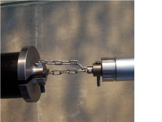
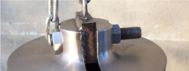
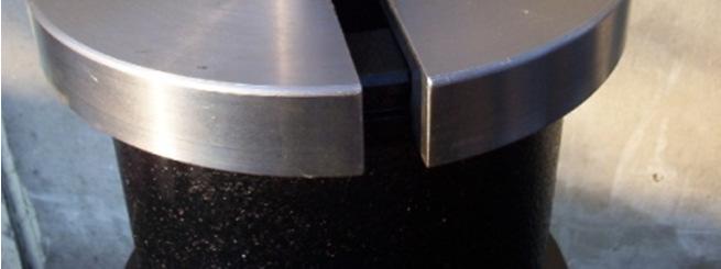

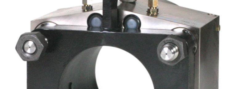
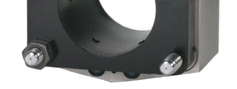


12 Product photographs 12
P-QUIP Ltd. Units 2&3, River Place, Paddockholm Ind Est, Kilbirnie, Ayrshire, KA25 7EN, Scotland U.K.
 1 www.pquip.com info@pquip.com P-QUIP Ltd Units 2&, River Place, Paddockholm Ind Est, Kilbirnie, Ayrshire, KA25 7EN, Scotland U.K. Tel: 01505 68544 Int. (44) 1505-68544 Fax: 01505 682756 Int. (44) 1505-682756
POWER STEERING PUMP REBUILDING SPK101 Read instructions completely before removal & disassembly
 POWER STEERING PUMP REBUILDING SPK101 Read instructions completely before removal & disassembly DISASSEMBLY: 1. Remove pump from car and allow to drain. 2. Remove pulley from front of pump. This requires
FRP Ball Valves INSTALLATION & MAINTENANCE MANUAL
 FRP Ball Valves INSTALLATION & MAINTENANCE MANUAL FRP BALL VALVES TABLE OF CONTENTS MAINTENANCE AND INSTALLATION INSTRUCTIONS 1. 2. 2.1 2.2 2.3 2.4 GENERAL...Page 1 HANDLING...1 Receiving and Storing...1
Installation Instructions
 Preparing your vehicle to install your brake system upgrade 1. Rack the vehicle. 2. If you don t have a rack, then you must take extra safety precautions. 3. Choose a firmly packed and level ground to
Maintenance Instructions
 General Note These instructions contain information common to more than one model of Bevel Gear Drive. To simplify reading, similar models have been grouped as follows: GROUP 1 Models 11, 0, 1,, (illustrated),,
Maintenance Information
 16573370 Edition 2 February 2014 Air Grinder 99V Series Maintenance Information Save These Instructions Product Safety Information WARNING Failure to observe the following warnings, and to avoid these
1984 Dodge W250 PICKUP
 1984 Dodge W250 PICKUP Submodel: Engine Type: V8 Liters: 5.2 Fuel Delivery: CARB Fuel: GAS Dana 44 MODELS THROUGH 1984 2. Raise and safely support the vehicle, then remove the wheel hub and bearings as
 AUTOGARD SERIES 820 TORQUE LIMITER Installation and Maintenance Manual DB0009 Issue 11 21 Feb 2017 British Autogard Ltd 2 Wilkinson Rd., Love Lane Industrial Estate, Cirencester, Glos., GL7 1YT UK Tel.
SB 160 QUICK REPAIR GUIDE FOR HALE THERMAL RELIEF VALVE TRV 120, TRV 170, TRV L
 Use this guide and PL729 to repair a Hale Thermal Relief Valve (TRV) when the valve does NOT vent above or does vent below 120 F (or 170 F for a TRV 170) or fails to provide the appropriate status indication
SERVICE GUIDE 8540-B 8549-B C. High-Pressure Lubricant Pump DESCRIPTION. Pump Assembly. Specifications
 SERVICE GUIDE 8540-B 8549-B1 8549-C DESCRIPTION The major components of the high-pressure pump models in this series consist of a(n): air-operated motor lubricant pressure controller (pressurtrol) double-acting
Service Tools. Service and Repair Manual Model 900/950/990 ITEM PART NO. DESCRIPTION ITEM PART NO. DESCRIPTION ITEM PART NO.
 12 1 3 2 4 5 8 10 6 7 9 11 14 24 12 13 17 22 29 18 23 25 19 26 15 20 27 21 16 22 33 37 38 32 31 36 30 34 35 40 41 42 43 ITEM PART NO. DESCRIPTION 1 9170 0231 30 LONG ALLEN KEY 2 9170 0737 20 3/32 PIN PUNCH
Sub Section Title Page No.
 Sub Section Title Page No. 1 Introduction 3 2 Routine Maintenance 3 3 Disassembly 4 3.1 Disassembly of Double Crank Design 4 3.2 Disassembly of Scotch Yoke Design 5 3.3 Disassembly of Actuator Cylinder
LOW PRESSURE BALANCED VALVE DIAPHRAGM BALANCED
 DIAPHRAGM BALANCED All Rights Reserved. All contents of this publication including illustrations are believed to be reliable. And while efforts have been made to ensure their accuracy, they are not to
NOTE: Visit our website at for video repair procedures, under the Tools section.
 Repair Instructions Hypro Repair Tools: Tool Box No. 3010-0168 1/4" Allen Wrench No. 3020-0008 Support Bars (2) No. 3010-0064 Port Brush No. 3010-0066 1/16" Allen Wrench No. 3020-0009 Brush Holder No.
Maintenance Information
 16573321 Edition 3 February 2014 Air Grinder Series 61H Maintenance Information Save These Instructions Product Safety Information WARNING Failure to observe the following warnings, and to avoid these
PLP Compression Dead-end & Jumper Terminal for ACSR & ACSS Conductors
 MARCH 2017 PLP Compression Dead-end & Jumper Terminal for ACSR & ACSS Conductors Be sure to read and completely understand this procedure before applying product. Be sure to select the proper PREFORMED
Maintenance Information
 Form 16573321 Edition 1 July 2004 Air Grinder Series 61H Maintenance Information Save These Instructions Always wear eye protection when operating or performing maintenance on this tool. Always turn off
INSTALLATION INSTRUCTION 88094
 INSTALLATION INSTRUCTION 88094 FOR RANCHO SUSPENSION SYSTEM RS6594B 4WD & 2WD NISSAN TITAN READ ALL INSTRUCTIONS THOROUGHLY FROM START TO FINISH BEFORE BEGINNING INSTALLATION Rev D IMPORTANT NOTES! WARNING:
Installation Instructions
 Installation Instructions Rear Disc Brake Conversion Kit Item # RC4001, RC4001X Applications: Mopar 7.25, 8.25, 9.25 Axles Thank you for choosing Leed Brakes for your automotive product needs. Before you
INSTALLATION AND MAINTENANCE OF TOP LOADING ARM
 INSTALLATION AND MAINTENANCE OF TOP LOADING ARM D TABLE OF CONTENTS 1. INTRODUCTION 04 2. SPECIFICATION OF THE REDLANDS LOADING ARM 04 3. INSTALLING THE LOADING ARM 3.1. Installation Procedures 05 4.
APCO ASR-400/450 SEWAGE AIR RELEASE VALVES
 APCO ASR-400/450 SEWAGE AIR RELEASE VALVES Instruction D12005 December 2012 Instructions These instructions provide installation, operation and maintenance information for the APCO ASR- 400/450 Sewage
TIDLAND WINDING SOLUTIONS. Tidland Leaf Shaft. User Manual. Series 650/650HD/750 MI 27L L
 TIDLAND WINDING SOLUTIONS Tidland Leaf Shaft User Manual EN Series 650/650HD/750 MI 27L691995 1 L IMPORTANT SAFETY INSTRUCTIONS When using this Tidland product, basic safety precautions should always be
Installation Instructions
 Installation Instructions Rear Disc Brake Conversion Kit Item # RC2001, RC2001X Applications: Mopar 8-3/4 & 9-3/4 Rear Axles Thank you for choosing Leed Brakes for your automotive product needs. Before
Installation, Operation, and Maintenance Manual. Welker Automatic Insertion Corrosion Coupon Device Model AID-1CC
 Installation, Operation, and Maintenance Manual Welker Automatic Insertion Corrosion Coupon Device Model The information in this manual has been carefully checked for accuracy and is intended to be used
#10 Setting Tool Assembly Product Family No (10)
") BRICO Oil Tools provides a dependable line of Wireline Pressure Setting Tools for the Wireline industry worldwide. Our engineering, high quality and service provides a cost effective alternative. BT#10
BRICO Oil Tools provides a dependable line of Wireline Pressure Setting Tools for the Wireline industry worldwide. Our engineering, high quality and service provides a cost effective alternative. BT#10
Maintenance and Repair
 Maintenance and Repair WARNING ALWAYS shut off the engine, remove key from ignition, make sure the engine is cool, and disconnect the spark plug and positive battery terminal from the battery before cleaning,
Hydraulic Transmission Jack, Telescopic
 Operating Instructions & Parts Manual Hydraulic Transmission Jack, Telescopic Model 4000 400 (Air Operated) Capacity 000 lbs. 000 lbs. Model 4000 Model 400 U.S. Patent No. 6,02,377! This is the safety
 DRUM BRAKE RIMS Periodic inspection of drum brake rims is necessary to determine indications of uneven or excessive wear. In general, brake rim failures other that regular wear are caused by brake linings
PNEUMATIC SLIDING VALVE
 INSTALLATION, OPERATION, & #: MM-SV001 6-23-09 Rev. A Page 1 of 8 PNEUMATIC SLIDING VALVE PART NUMBERS (Including, but not inclusive) SV704MSTS, SV714MSTS, SV754MSTS, SV764MSTS, SV774MSTS, SV706MSTS, SV716MSTS,
EQUALIZER International Limited 10T(I) Integral Hydraulic Spreading Wedge Repair Instruction Manual
 Integral Hydraulic Spreading Wedge Repair Instruction Manual") EQUALIZER International Limited 10T(I) Integral Hydraulic Spreading Wedge Repair Instruction Manual INDEX THE EQUALIZER 10T(I) Integral Hydraulic Wedge SECTION CONTENTS PAGE NO (S) 03 04 05 06 07 08 09
EQUALIZER International Limited 10T(I) Integral Hydraulic Spreading Wedge Repair Instruction Manual INDEX THE EQUALIZER 10T(I) Integral Hydraulic Wedge SECTION CONTENTS PAGE NO (S) 03 04 05 06 07 08 09
Maintenance Information
 16572679 Edition 2 May 2014 Air Drill QP Series Maintenance Information Save These Instructions Product Safety Information WARNING Failure to observe the following warnings, and to avoid these potentially
Maintenance Information
 80234313 Edition 1 June 2006 Air Grinder, Die Grinder, Sander and Belt Sander Series G1 (Angle) Maintenance Information Save These Instructions WARNING Always wear eye protection when operating or performing
Crispin Valves Operating Guide. Crispin
 Crispin Valves Operating Guide Crispin Since 1905 Crispin Multiplex Manufacturing Co. 600 Fowler Avenue Berwick, PA 18603 1-800-AIR-VALV T: (570) 752-4524 F: (570) 752-4962 www.crispinvalve.com sales@crispinvalve.com
HIGH PRESSURE CONTROL VALVE PISTON BALANCED
 PISTON BALANCED All Rights Reserved. All contents of this publication including illustrations are believed to be reliable. And while efforts have been made to ensure their accuracy, they are not to be
Input Adjusting Ring Leak Repair Procedure for Meritor MT-14X Series Forward Differential Carriers
 Revised 01-16 Technical Bulletin Input Adjusting Ring Leak Repair Procedure for Meritor MT-14X Series Forward Differential Carriers Revised 1 Technical 01- Bulletin 16 Hazard Alert Messages Read and observe
Maintenance Information
 45528270 Edition 1 June 2007 Barring Motor T480 Series Maintenance Information Save These Instructions WARNING Always wear eye protection when operating or performing maintenance on this Barring Motor.
Service Manual. Climate Control Inc.
 SECTION 2 Service - Clutch Servicing (Removal & Installation) - Shaft Seal Servicing (Removal & Installation) - Head & Valve Plate Servicing (Removal & Installation) - Baseplate Servicing (Removal & Installation)
INSTRUCTION MANUAL AND PARTS LIST FOR SERIES 8L-630J AND 630M WARNING
 INSTRUCTION MANUAL AND PARTS LIST FOR SERIES 8L-630J AND 630M WARNING READ CA-l AND TIDS INSTRUCTION MANUAL PRIOR TO INSTALLATION, OPERATION OR MAINTENANCE WARNING This Instruction Manual and General Instructions
RUGBY HOIST CYLINDERS SERVICE BULLETIN
 TRUCK BODIES & EQUIPMENT INTERNATIONAL, Inc. Website: www.rugbymfg.com E-mail: sales@rugbymfg.com Phone: (701) 776-5722 Toll Free: (800) 869-9162 RUGBY HOIST CYLINDERS SERVICE BULLETIN This bulletin applies
These instructions are applicable to the following models: ARI 1118 ARI 1148
 INSPECTION & MAINTENANCE BULLETIN ARI 1118 & 1148 Safety Relief Valve These instructions are applicable to the following models: ARI 1118 ARI 1148 Only AAR class F facilities are certified to recondition,
DB4604 GMR-SD and GMR40-SD Disc Brake Caliper - Spring Applied, Air Released
 DB464 GMR-SD and GMR4-SD Disc Brake Caliper - Spring Applied, Air Released Nominal dimensions given. For specific dimensions please contact Twiflex Limited. For GMR Mk 2 caliper details see DB 364 Air
These instructions are applicable to the following models: ARI 1108 ARI HP1108
 INSPECTION & MAINTENANCE BULLETIN ARI 1108 & HP1108 Safety Relief Valve These instructions are applicable to the following models: ARI 1108 ARI HP1108 Only AAR class F facilities are certified to recondition,
SW14.5TI INTEGRAL HYDRAULIC FLANGE SPREADING WEDGE. Repair Manual INNOVATION IN ITS MOST FUNCTIONAL FORM
 SW14.5TI INTEGRAL HYDRAULIC FLANGE SPREADING WEDGE Repair Manual info@equalizerinternational.com www.equalizerinternational.com INNOVATION IN ITS MOST FUNCTIONAL FORM INDEX SECTION CONTENTS PAGE NO. 1
JL SHIELD TIRE CARRIER INSTALLATION INSTRUCTIONS
 JL SHIELD TIRE CARRIER INSTALLATION INSTRUCTIONS TOOLS NEEDED 3/4 Wrench 3/4 Socket 9/16 Wrench or Socket 1 1/2 Socket 1 1/8 Wrench 13mm Socket Torque Wrench for 1 1/2 Socket HARDWARE 2-1/2 X 2 Hex Bolt
SERIES PC INSTRUCTION AND OPERATION MANUAL
 MEGGA SERIES PC INSTRUCTION AND OPERATION MANUAL Models PCT and PCF Close-coupled and frame-mounted single-stage horizontal end-suction pumps. WARNING: Read this manual before installing or operating this
DELTA O-RING CARTRIDGE SEAL ASSEMBLY AND INSTALLATION INSTRUCTIONS INTRODUCTION:
 DELTA O-RING CARTRIDGE SEAL ASSEMBLY AND INSTALLATION INSTRUCTIONS INTRODUCTION: These instructions are provided to familiarize the user with the seal and its use. The instructions must be read carefully
Service Sheet SSJ0452P. J0452 Coupler with Pump API Coupler
 Sheet:, 17/04/12, Rev: 2 As a part of a continuous commitment to product development the company reserves the right to alter the specification of its products without prior notice J0452 Coupler with Pump
DEUBLIN. DEUBLIN Unions H57 H67 H87
 Instructions for Installation and Maintenance Installation Instructions For DEUBLIN H57 H67 H87 19.4.2013 DEUBLIN Italiana S.r.l. Via Guido Rossa, 9 40050 Monteveglio (BO) Italy ++39.051.835611 Fax: ++39.051.832091
DEUBLIN. Installation Instructions DEUBLIN Unions H57 H67 H87
 Instructions for Installation and Maintenance Installation Instructions For DEUBLIN H57 H67 H87 06.4.2012 DEUBLIN Italiana S.r.l. Via Guido Rossa, 9 40050 Monteveglio (BO) Italy ++39.051.835611 Fax: ++39.051.832091
Mandatory X Information Recommended Change. Series/Parts Affected: LS40D, LS40TD, LS50TD and LS60TD Concrete Pumps
 Service Bulletin No. CP20060428 Subject: Remix Shaft Coupler Retrofit Kit Model: LS40D, LS40TD, LS50TD & LS60TD Product Group: Concrete Pump Date: April 28, 2006 SERVICE BULLETIN Group: CP Mandatory X
Servicing the Tool. Service Kit SERVICE KIT. For all servicing we recommend the use of the service kit (part number (S)).
).") Servicing the Tool Service Kit For all servicing we recommend the use of the service kit (part number 07900-04750(S)). SERVICE KIT ITEM PART Nº DESCRIPTION Nº OFF ITEM PART Nº DESCRIPTION Nº OFF 07900-00002
Servicing the Tool Service Kit For all servicing we recommend the use of the service kit (part number 07900-04750(S)). SERVICE KIT ITEM PART Nº DESCRIPTION Nº OFF ITEM PART Nº DESCRIPTION Nº OFF 07900-00002
Max IV Rear Axle Replacement For models after Serial Number and all rear splined axle replacements.
 Max IV Rear Axle Replacement For models after Serial Number 19089 and all rear splined axle replacements. 10/8/03 Max IV Snap Ring Rear Axle replacement.doc Tools required: 9/16 Wrench 6 Extension Steel
OPERATING INSTRUCTIONS & SERVICE MANUAL BLUE MAX II HYDROSTATIC TEST PUMP
 PAGE 1 OF 10 OPERATING INSTRUCTIONS & SERVICE MANUAL BLUE MAX II HYDROSTATIC TEST PUMP EFFICIENT, EASY OPERATION Air operated pump Wide range of pressures and volumes Easy to operate controls Output pressure
3.2 DRIVE TORQUE HUB. Roll, Leak and Brake Testing SECTION 3 - CHASSIS & TURNTABLE. 3-2 JLG Lift
 3.2 DRIVE TORQUE HUB Roll, Leak and Brake Testing 10 LUG PATTERN Torque-Hub units should always be roll and leak tested before disassembly and after assembly to make sure that the unit's gears, bearings
2. Disconnect negative battery cable to avoid possible fuel discharge if an accidental attempt is made to start the engines.
 PART #25001 LT1 Adjustable Fuel Pressure Regulator, 1994-1997 PACKING LIST Before installation, use this check list to make sure all necessary parts have been included. ITEM QTY CHECK PART NUMBER DESCRIPTION
AIRGO MISTING SYSTEM MAINTENANCE
 AIRGO MISTING SYSTEM MAINTENANCE WARNING: Disconnect the fan and misting pump from power before servicing. Service schedule Schedule Procedure 50 hours of operation Initial oil change 300 hours of operation,500
Installation instructions
 Installation instructions Akrapovič Exhaust System: Slip-On for the Porsche 911 Carrera (type 991) Porsche 911 Carrera S (type 991) Porsche 911 Carrera 4 (type 991) Porsche 911 Carrera 4S (type 991) Please
Table of Contents Visual Inspection and Neutralizing... 3 Disassembly
 1 Table of Contents Visual Inspection and Neutralizing... 3 Disassembly... 3... 4... 4 Cleaning... 4 Inspection... 4 Reconditioning of Valve Seats... 5 Lapping Procedures... 5 Lapping Blocks... 5 Lapping
INSTALLATION INSTRUCTION 88088
 INSTALLATION INSTRUCTION 88088 For Rancho Suspension Systems RS6588 & RS6589: FORD F-150 READ ALL INSTRUCTIONS THOROUGHLY FROM START TO FINISH BEFORE BEGINNING INSTALLATION Rev B IMPORTANT NOTES! WARNING:
Coro-Vane Maintenance CP471. and Disassembly
 Coro-Vane Maintenance CP471 and Disassembly CoroVane Pumps Pumps all have discharge and suction pressure openings. The following slides depict a 1021, but all standard pumps are repaired the same. Grease
INSTRUCTION MANUAL AND PARTS LIST FOR PG/RG3D_-187, 218, 250 and 312 SERIES PUMPS
 INSTRUCTION MANUAL AND PARTS LIST FOR PG/RG3D_-187, 218, 250 and 312 SERIES PUMPS WARNING This Instruction Manual and General Instructions Manual, CA-1, should be read thoroughly prior to pump installation,
Maintenance Manual 4½-INCH INTERNAL VALVE F635 SERIES
 Maintenance Manual 4½-INCH INTERNAL VALVE F635 SERIES REVISION 1.0 11/01/2004 LIST OF EFFECTIVE PAGES On a revised page, the portion of text or illustrations affected by the change is indicated by a vertical
INSTALLATION, OPERATION AND MAINTENANCE INSTRUCTIONS
 INSTALLATION, OPERATION AND MAINTENANCE INSTRUCTIONS Contents Section 1. General Observations... 2 2. Operation... 4 3. Control During Operation... 5 4. Trouble Shooting... 6 5. Maintenance... 7 Please
Installation instructions
 Installation instructions Akrapovič Exhaust System Racing for the BMW G310R *505721* EN Revision 1.0 01/2017 www.akrapovic.com www.akrapovic.com Congratulations on purchasing the Akrapovič exhaust system.
INSTALLATION, OPERATION AND MAINTENANCE MANUAL FOR T40 Mk. 2 DISC BRAKE CALIPER M1492
 INSTALLATION, OPERATION AND MAINTENANCE MANUAL FOR T40 Mk. 2 DISC BRAKE CALIPER AMENDMENT AND ISSUE RECORD Amendment Number Issue Date Issued by - 01 A.D. (i) INDEX PAGE 1 Installation 1 1.1 General description
DeZURIK 24 and Larger BHP High Performance Butterfly Valves WITH (FB) FYRE-BLOCK SEAT
 FYRE-BLOCK SEAT") 24 and Larger BHP High Performance Butterfly Valves WITH (FB) FYRE-BLOCK SEAT Instruction D10497 April 2015 BHP High Performance Butterfly Valves (S2, S3, S5, AA, HC, ML, T2 & T5 Shafts) Instructions These
24 and Larger BHP High Performance Butterfly Valves WITH (FB) FYRE-BLOCK SEAT Instruction D10497 April 2015 BHP High Performance Butterfly Valves (S2, S3, S5, AA, HC, ML, T2 & T5 Shafts) Instructions These
Installation & Maintenance Manual SPRING ENGAGED FRICTION CLUTCHES THROUGH SHAFT MOUNT - BALL BEARING PILOT REGULAR DUTY
 Installation & Maintenance Manual SPRING ENGAGED FRICTION CLUTCHES THROUGH SHAFT MOUNT - BALL BEARING PILOT REGULAR DUTY Catalog Products: E3A2R-STH E4A2R-STH E5A2R-STH E6A2G-STH And non-catalog variations
Nor East. Instructions Safety Messages. Inspection. Parts. DeZURIK Service. Type 05 Pneumatic Actuator Used With Globe Valves
 Instructions Safety Messages These instructions are intended for personnel who are responsible for installation, operation and maintenance of your DeZURIK Actuator. All safety messages in the instructions
Maintenance. Daily. Shutdown Procedure. Periodically. During Freezing Temperatures
 Maintenance Daily Check the oil level and the condition of the oil. When the pump is operating, the oil in the pump housing gets warm and expands, filling into the oil reservoir. Depending on the type
Installation instructions
 Installation instructions Akrapovič Exhaust System Optional Header for the BMW R 1250 GS BMW R 1250 GS Adventure *506813* EN Revision 1.0 12/2018 Congratulations on purchasing the Akrapovič exhaust system.
4 - Way Control 4 - Way Control 4 - Way Control with lock
 INSTALLATION / OPERATION / MAINTENANCE 1. DESCRIPTION MODEL 0-02 (Full Internal Port) Powertrol Valve This manual contains information for installation, operation and maintenance of the Cla-Val Co. 0-02
Maintenance Information
 16573347 Edition 2 February 2014 Air Grinder Series 88H Maintenance Information Save These Instructions Product Safety Information WARNING Failure to observe the following warnings, and to avoid these
Anderson Greenwood Series 800 POSRV Installation and Maintenance Instructions
 Before installation these instructions must be fully read and understood Table of contents 1. General valve description and start-up... 1 2. Main valve maintenance... 2 3. Pilot maintenance... 6 4. Pilot
Installation instructions
 Installation instructions Akrapovič Exhaust System Racing for the Kawasaki Z650 Kawasaki Ninja 650 *505634* EN Revision 1.0 12/2016 www.akrapovic.com www.akrapovic.com Congratulations on purchasing the
Maintenance Information
 80234313 Edition 2 May 2014 Air Grinder, Die Grinder, Sander and Belt Sander Series G1 (Angle) Maintenance Information Save These Instructions Product Safety Information WARNING Failure to observe the
Spring Brake Application
 Technical Tip Maxibrake I Series Spring Brakes Disassembly, Inspections and Reconditioning Instructions Maxibrake I Series spring brake products are mechanical devices and are subject to wear after extended
Valveworks USA Operation and Maintenance Booklet Model FC
 Operation and Maintenance Booklet Model FC MODEL FC 3000, 5000, 10000, & 15000 W.P. FLOATING SLAB GATE VALVES 1 13/16-2 1/16-2 9/16-3 1/16-4 1/16 BOOKLET APPROVED BY: INTRODUCTION In appreciation to you
Service Guide. High-Pressure Grease Pump. 100 psi (6.8 bar) High-Pressure Pump Model 7785 Series Specifications
 High-Pressure Pump Model 7785 Series Specifications") Description Service Guide 7785-A5 7785-B5 7785-MA The major components of the pump models in the 7785 series consist of an air-operated motor and a pump tube. The air motor connects directly to the double-acting
Description Service Guide 7785-A5 7785-B5 7785-MA The major components of the pump models in the 7785 series consist of an air-operated motor and a pump tube. The air motor connects directly to the double-acting
CONTENTS. Product Features and Specifications...1. Installation Requirement Steps of Installation.. 5. Exploded View Test Run...
 CONTENTS Product Features and Specifications...1 Installation Requirement... 4 Steps of Installation.. 5 Exploded View...21 Test Run...26 Operation Instruction...27 Maintenance... 28 Trouble Shooting...
Discount-Equipment.com
 REQUIRED TOOLS LS Series Remix Shaft Installation Instructions /8", /6", /2" Allen Wrenches Snap Ring Pliers (Light Duty) /" Combination Wrench Loctite #22 Blue /" Socket w/ /8" Ratchet Electric Drill
MAINTENANCE AND REPAIR INSTRUCTIONS
 MAINTENANCE AND REPAIR INSTRUCTIONS TYPE TH PUMPS Peerless Pump Company Indianapolis IN, 46207-7026 4849357 TABLE OF CONTENTS Maintenance Page 1 & 2 Disassembly Page 5 & 6 Impeller Clearance 3 Reassembly
Installation instructions
 Installation instructions Akrapovič Exhaust System Racing for the Kawasaki Versys 650 *506231* EN Revision 1.0 11/2017 www.akrapovic.com www.akrapovic.com Congratulations on purchasing the Akrapovič exhaust
Installation instructions
 Installation instructions Akrapovič Exhaust System Racing Open for the Yamaha MT-07 *504316* EN Revision 1.0 02/2016 www.akrapovic.com www.akrapovic.com Congratulations on purchasing the Akrapovič exhaust
Maintenance Manual 6-INCH INTERNAL VALVE F620 SERIES
 Maintenance Manual 6-INCH INTERNAL VALVE F620 SERIES REVISION 1.1 03/15/2002 LIST OF EFFECTIVE PAGES On a revised page, the portion of text or illustrations affected by the change is indicated by a vertical
MEMORY SEAL BALL VALVES MAINTENANCE MANUAL 2 12, Class 150 & 300, Regular Port, Flanged Unibody
 MEMORY SEAL BALL VALVES MAINTENANCE MANUAL 2 12, Class 150 & 300, Regular Port, Flanged Unibody I INTRODUCTION These rugged, versatile, high performance, regular port, ball valves meet all requirements
Fisher 1061 Pneumatic Piston Rotary Actuator with Style H & J Mounting Adaptations
 Instruction Manual 1061 H & J Actuator Fisher 1061 Pneumatic Piston Rotary Actuator with Style H & J Mounting Adaptations Contents Introduction... 1 Scope of Manual... 1 Description... 2 Specifications...
Discount-Equipment.com
 LS40D, LS40TD, LS50TD, LS60TD LS-Series Remix Shaft Coupler Retrofit Kit Installation Instructions The following instructions are intended to assist the user in the installtion of the LS-Series Remix Shaft
Colt Series C400, C500
 Colt Series C400, C500 RP/IS-A-C400/C500 C400 OSY Reduced Pressure Zone Assemblies Reduced Pressure Detector Assemblies Sizes: 2 1 2" 10" (65 250mm) Installation Service Repair Kits Maintenance For other
Installation instructions
 Installation instructions Akrapovič Exhaust System Racing for the Yamaha YZF-R25 Yamaha YZF-R3 *504503* EN Revision 1.0 02/2016 www.akrapovic.com www.akrapovic.com Congratulations on purchasing the Akrapovič
AVK SAUDI VALVES MANUFACTURING COMPANY
 AVK SAUDI VALVES MANUFACTURING COMPANY AVK SERIES 24 - HIGH PRESSURE, WET BARREL HYDRANT FIELD MAINTENANCE AND INSTRUCTION MANUAL TABLE OF CONTENTS EXPLODED ASSEMBLY / PARTS LIST INTRODUCTION / DESCRIPTION
This file is available for free download at
 This file is available for free download at http://www.iluvmyrx7.com This file is fully text-searchable select Edit and Find and type in what you re looking for. This file is intended more for online viewing
REPAIR PROCEDURES MANUAL
 REPAIR PROCEDURES MANUAL PVX Series Vane Pumps A Design Series Step-by-Step Guide to Troubleshooting and Repairing PVX Series Vane Pumps Introduction Thank you for choosing Continental Hydraulics PVX Vane
ORIGA SYSTEM PLUS Guides, Brakes and Valves for Modular Linear Drive Systems OSP Appendix to the Operating Instructions
 ORIGA SYSTEM PLUS Guides, Brakes and Valves for Modular Linear Drive Systems OSP Appendix to the Operating Instructions TAll personnel who have anything to do with the OSP fitted with guides, brakes or
Engine Leaks and Cures
 Engine Leaks and Cures The following information, printed in blue, is taken with permission from the website of Antique Engine Rebuilding located in Skokie Illinois. I have inserted a few pictures within
POWER STEERING TO INDEX POWER STEERING SYSTEM PRECAUTIONS... OPERATION CHECK... PROBLEM SYMPTOMS TABLE... VANE PUMP ASSEMBLY COMPONENTS...
 TO INDEX STEERING POWER STEERING POWER STEERING SYSTEM PRECAUTIONS.............................................. OPERATION CHECK......................................... PROBLEM SYMPTOMS TABLE.................................
Installation Instructions
 Installation Instructions Rear Disc Brake Conversion Kit Item # RC1001, RC1001X Applications: 64-72 A-body, 67 F-Body, 63-67 X-body with Non Staggered Shocks Thank you for choosing GPS Auto for your automotive
Installation instructions
 Installation instructions Akrapovič Exhaust System Racing for the Yamaha MT-03 Yamaha R3 *505481* EN Revision 1.0 07/2016 www.akrapovic.com www.akrapovic.com Congratulations on purchasing the Akrapovič
OVERLOAD CLUTCHES FOR INDEX DRIVES
 The Driving Force in Automation OVERLOAD CLUTCHES FOR INDEX DRIVES WARNING WARNING This is a controlled document. It is your responsibility to deliver this information to the end user of the CAMCO indexer.
1988 Chevrolet Pickup V SUSPENSION - FRONT (4WD)' 'Front Suspension - "V" Series 1988 SUSPENSION - FRONT (4WD) Front Suspension - "V" Series
' 'Front Suspension - V Series 1988 SUSPENSION - FRONT (4WD) Front Suspension - V Series") 1988 SUSPENSION - FRONT (4WD) Front Suspension - "V" Series DESCRIPTION NOTE: Vehicle serial numbers used in this article has been abbreviated for common reference to Chevrolet and GMC models. Chevrolet
1988 SUSPENSION - FRONT (4WD) Front Suspension - "V" Series DESCRIPTION NOTE: Vehicle serial numbers used in this article has been abbreviated for common reference to Chevrolet and GMC models. Chevrolet
MODEL 2604 WARNING <THESE INSTRUCTIONS MUST BE GIVEN TO THE END USER> Custom 5th Wheel Hitch Mounting Rail Installation Instructions
 B&W Trailer Hitches 1216 Hawaii Rd / PO Box 186 Humboldt, KS 66748 P:620.473.3664 F:620.869.9031 Custom 5th Wheel Hitch Mounting Rail Installation Instructions