Fundamentals of Steam Locomotive Tractive Force
|
|
|
- Blaze Douglas
- 6 years ago
- Views:
Transcription
1 Tractive Force. Fundamentals of Steam Locomotive Tractive Force By Jeffrey G. Hook January 4, 2016, Revised February 12, 2017 An ordinary steam locomotive relies upon rotational force or torque developed at the driving wheels produced by the machinery of the locomotive and friction between the driving wheels and the rails to propel it and any cars attached along the track. The propelling force developed is generally referred to as tractive force or tractive effort. For the remainder of this article references to a steam locomotive shall be understood to be an ordinary two cylinder, reciprocating double acting, single expansion, non condensing, adhesion or friction traction, side rod driven steam locomotive. Rack drive, geared drive, three or more cylinder, multiple expansion compound or steam turbine drive, etc., etc., steam locomotives are not considered. Derivation of Tractive Force, Single Cylinder Steam Engine Example. A steam locomotive may be thought of as comprising two single cylinder reciprocating double acting steam engines. One on the left side and the other on the right side of the locomotive. Each engine imparting rotation to a common crank shaft, that being the main driving axle of the locomotive. Figure 1 illustrates such a single cylinder steam engine having a rope winding drum coaxially attached to the crank shaft. Given the diameter of the cylinder and piston, and the steam pressure applied in the cylinder, a theoretical force of 50,000 pounds is applied to the crank pin by the main rod. Given the surface of the rope winding drum and the center of the crank pin are the same distance from the center of the crank shaft, for the crank pin position illustrated, theoretically a weight of 50,000 pounds may be raised by the wire rope attached to the winding drum. The effects of inertia and losses due to the angularity of the main rod and friction between moving parts of the engine are ignored.
2 Formula 1 may be used to ascertain the piston force of the engine in Figure 1. Fp = Pc * ( C / 2 ) 2 * Pi (Formula 1) where: Fp = Piston force in pounds. Pc = Steam pressure in cylinder in pounds per square inch gauge. C = Cylinder bore diameter or piston diameter in inches. Pi = Using Figure 1 engine: Pc = p.s.i.g. C = 19 inches. results in: Fp = 50,000 pounds = * ( 19 / 2 ) 2 * In Figure 2 the rope winding drum of the engine has been increased to 48 inches in diameter and better represents the tread diameter of a driving wheel of a steam locomotive. In Figure 2 the surface of the rope winding drum is 24 inches from the center of the crank shaft and the center of the crank pin is 12 inches from the center of the crank shaft. Because of this dimensional difference the force developed at the rim of the rope winding drum is less than the piston force transmitted to the crank pin by the main rod. The effects of inertia of and losses due to the angularity of the main rod and friction between moving parts of the engine are ignored.
3 Rule II of Levers. To find the delivered force, multiply the applied force by the length of the lever between the applied force and the fulcrum, and divide by the length of the lever between the delivered force and the fulcrum. The foregoing may be applied to the engine illustrated in Figure 2 by assuming the center line of the crank shaft is the fulcrum, the center line of the crank pin is the point of applied force, and the surface of the rope winding drum (tread surface of a locomotive driving wheel) is the point of delivered force. Fd = Fa * La / Ld (Formula 2) where: Fd = Delivered force in pounds. Fa = Applied force in pounds or piston force Fp in pounds from Formula 1. La = Length of lever between fulcrum and applied force in inches. Ld = Length of lever between fulcrum and delivered force in inches. Using Figure 2 engine: Fa = 50,000 pounds. La = 12 inches. Ld = 24 inches. results in: Fd = 25,000 pounds = 50,000 * 12 / 24 If the crank shaft of the engine in Figure 2 is considered to be the main driving axle of a single driving axle locomotive, then the two 48 inch diameter driving wheels attached would share the 25,000 pounds of force illustrated resulting in 12,500 pounds of tractive force at the tread surface of each of the two driving wheels. Effect of Crank Pin Position. If the engine in Figure 3 is considered to be rotating clockwise, the maximum torque developed at the crank shaft derived from the force applied to the crank pin by the main rod will occur when the crank pin is near the 90 degree position during the leftward stroke of the piston, and near the 270 degree position during the rightward stroke of the piston. In any other crank pin position the effective crank arm length is reduced, thus for any given cylinder steam pressure the torque developed at the crank shaft will be reduced when compared to the 90 degree or 270 degree crank pin positions.
4 Cylinder Steam Pressure During Stroke of Piston. Figure 4 illustrates simplified theoretical cylinder steam pressure from the beginning to the end of the stroke of the piston of a typical engine illustrated in Figure 3. This occurring on the right side of the piston to produce one-half a revolution of the crank shaft (0 degrees to 90 degrees to 180 degrees), then the similar occurring on the left side of the piston to complete the revolution of the crank shaft (180 degrees to 270 degrees to 0 degrees). The valve gear of the engine is taken to be set for maximum cut-off (set for full forward or full backward, typical when starting a steam locomotive), thereby providing maximum cylinder steam pressure during the majority of the stroke of the piston. In this case being 90 percent. In addition the engine is considered to be operating under maximum load with wide open throttle and is rotating at low speed. Under these conditions the maximum cylinder steam pressure will be less than although near the boiler steam pressure. Combined Effect of Crank Pin Position and Cylinder Steam Pressure. Figure 5 illustrates the theoretical torque developed by the engine in Figure 3 as the crank shaft makes one revolution. The serpentine line has been plotted from data resulting from calculations that take into consideration the varying effective crank arm length, the varying steam pressure (admission pressure) on the piston tending to move the piston in the direction of rotation of the crank shaft, and the varying exhaust steam pressure (back pressure) on the opposite side of the piston tending to retard the movement of the piston. The engine is again considered to be operating under maximum load with wide open throttle and rotating at low speed. The effects of inertia of moving parts of the engine are ignored.
5 Coupled Driving Wheels. Figure 6 illustrates the mechanical scheme typically used to couple the driving wheels of a steam locomotive. If the locomotive in Figure 6 is considered to be moving forward and toward the right, then the right side crank pins are referred to as leading the left side crank pins. Whether the locomotive designer specified the right side crank pins to lead the left or the left side crank pins to lead the right is of no consequence. Regardless of the number of coupled driving axles or on what side the crank pins lead the other; the primary design element is the 90 degree angular difference between the crank pins on the left side and right side of the locomotive. Positioning the crank pins in this manner results in the four force impulses produced by the pistons of the left and right sides of the locomotive to occur at approximately equal intervals as the driving axle or axles make each revolution. This also provides for the starting of the locomotive in any rotational position of the driving wheels given that when one side of the locomotive is on either dead center the other side is midway between its dead centers. Torque Diagram for Two Cylinder Steam Locomotive. Figure 7 illustrates a theoretical torque diagram for a steam locomotive produced by calculations similar to those used for producing the torque diagram of Figure 5. The two black color serpentine lines illustrate the theoretical torque produced by the individual double acting steam engines on the left and right sides of the locomotive. The red color serpentine line illustrates the theoretical combined torque or tractive force produced by the locomotive given the engines of the left and right sides are coupled together by the driving axles as illustrated in Figure 6. The locomotive in this case is considered to be operating at low speed under maximum load, at maximum allowed boiler steam pressure, with wide open throttle and the valve gear set for maximum cut-off. The effects of inertia of moving parts of the engine are ignored.
6 Tractive Force Formulas. Torque diagrams such as Figure 7 clearly illustrate the varying nature of the tractive force produced by a steam locomotive under the theoretical conditions described. The data points calculated in order to produce a torque diagram may also be used to ascertain the mean or average tractive force produced. Of more practical use would be a mathematical formula the result of which would be an estimate of the mean tractive force produced, thus avoiding the necessity of calculating the numerous data points required to construct a torque diagram. Figure 7 illustrates the minimum combined tractive force of a steam locomotive is produced at points in the rotation of the driving wheels at which the torque produced by the individual engines of either the left or right side of the locomotive is the greatest. By combining previously described Formulas 1 and 2, Formula 3 is produced the result of which may be considered to be either the estimated maximum torque produced independently by each of the left side or right side engines of the locomotive, or the estimated minimum combined tractive force Tmin produced by the locomotive as a whole. Tmin = Pc * ( C / 2 ) 2 * Pi * La / Ld (Formula 3) where: Tmin = Tractive force minimum in pounds. Pc = Steam pressure in cylinder in pounds per square inch gauge. C = Cylinder bore diameter or piston diameter in inches. Pi = La = Length of lever between fulcrum and applied force in inches, or distance from center of crank shaft to center of crank pin in inches, or one-half the stroke of the piston in inches. Ld = Length of lever between fulcrum and delivered force in inches, or distance from center of crank shaft to tread of diving wheel in inches, or one-half the driving wheel diameter in inches. In Formula 3 the length of the stoke of the piston may be substituted for La if the driving wheel diameter is substituted for Ld, thereby producing Formula 4. Tmin = Pc * ( C / 2 ) 2 * Pi * S / D (Formula 4) where: Tmin = Tractive force minimum in pounds. Pc = Steam pressure in cylinder in pounds per square inch gage. C = Cylinder bore diameter or piston diameter in inches. Pi = S = Stroke of the piston in inches. D = Driving wheel diameter in inches. In Formula 4 instead of finding the area of the piston by using ( C / 2 ) 2 * Pi, the area of the piston may be found by using C 2 * ( Pi / 4 ). Pi / 4 producing constant K1 = , thereby producing Formula 5. Tmin = Pc * C 2 * K1 * S / D (Formula 5) where: Tmin = Tractive force minimum in pounds. Pc = Steam pressure in cylinder in pounds per square inch gauge. C = Cylinder bore diameter or piston diameter in inches. K1 = S = Stroke of the piston in inches. D = Driving wheel diameter in inches.
7 Rated Tractive Force, The Common Formula. The reader is reminded that for this article references to a steam locomotive shall be understood to be an ordinary two cylinder, reciprocating double acting, single expansion, non condensing, adhesion or friction traction, side rod driven steam locomotive. Rack drive, geared drive, three or more cylinder, multiple expansion compound or steam turbine drive, etc., etc., steam locomotives are not considered. The ratio between the minimum and the mean tractive force of Figure 7 may be used to establish the value of constant K2 that when multiplied by the minimum tractive force Tmin may be used to estimate the mean tractive force. In the case of the torque diagram of Figure 7 the ratio will be discovered to be approximately 1:1.2, therefore constant K2 is assigned the value of 1.2. In the previously described formulas steam pressure in the cylinder Pc was used in the calculations. In practice the steam pressure in the cylinder is not actually ascertained and instead is estimated to be a pressure less than the maximum boiler steam pressure specified for the locomotive. The amount of the estimated pressure loss establishes the value of constant K3 and is determined by taking into consideration the expected pressure losses in the steam conveying system from the boiler to the cylinders, the cylinder admission steam pressure characteristics as theoretically illustrated by Figure 4 and the exhaust steam back pressure characteristics (not illustrated) tending to retard the motion of the piston. The admission and exhaust pressure characteristics taken to be those resulting from the locomotive valve gear being set for maximum cut-off and the locomotive operating under maximum load with wide open throttle and moving at low speed. By incorporating into Formula 5 the constants K2 and K3 Formula 6 is produced the result of which is designated as the rated tractive force T of a steam locomotive. T = K1 * K2 * K3 * P * C 2 * S / D (Formula 6) where: T = Rated tractive force in pounds. K1 = K2 = 1.2 K3 = 0.90 P = Maximum boiler steam pressure in pounds per square inch gauge. C = Cylinder bore diameter in inches. S = Stroke of the piston in inches. D = Driving wheel diameter in inches. The constants K1, K2 and K3 of Formula 6 may be multiplied together resulting in one constant K having a value of 0.85, thereby producing Formula 7 that in the United States is the commonly published formula for ascertaining the rated tractive force T of an ordinary steam locomotive. T = K * P * C 2 * S / D (Formula 7) where: T = Rated tractive force in pounds. K = 0.85 P = Maximum boiler steam pressure in pounds per square inch gauge. C = Cylinder bore diameter in inches. S = Stroke of the piston in inches. D = Driving wheel diameter in inches. Constant K. In many instances Formula 7 is published using a designated value instead of the variable letter K. T = 0.85 * P * C 2 * S / D (Formula 7 alternative)
8 The constant value of 0.85 in Formula 7 alternative is occasionally referred to as being a value that represents solely the difference between the maximum boiler steam pressure and the expected steam pressure in the cylinders of the locomotive. This explanation is not entirely correct as multiple elements, previously described constants K1, K2 and K3, are in fact involved when establishing the value of constant K. Rated tractive force data from the Locomotive Cyclopedia of American Practice provides an example of the value of constant K being adjusted in order to take into consideration more detailed operational circumstances. Table 1 Values of Constant K for an Ordinary Steam Locomotive from the Locomotive Cyclopedia of American Practice. Main Valve Maximum Cut-off Percent Constant K for Main Valve without Auxiliary Ports Constant K for Main Valve with Auxiliary Ports with 80% Minimum Cut-off The 1922 through editions of the Locomotive Cyclopedia define auxiliary starting port as, A small opening or port in the valve chamber bushing which is uncovered by the valve before the main ports are opened. Its purpose is to allow steam to enter the cylinders for starting the engine where the steam lap is greater than about 1 inch. From a review of data and drawings published in the aforementioned editions it may be concluded that only a small minority of steam locomotives constructed in the United States were equipped with auxiliary starting ports. Due to the added complexity required for their construction and their likely minimal operational benefit, auxiliary starting ports are typically not applied on a miniature practice steam locomotive even though its full size practice example was so equipped. Rated Tractive Force, Conditions in Effect or Ignored. The use of the term rated tractive force indicates the resulting value is an estimate of steam locomotive mean or average tractive force developed at the treads of the driving wheels and is based on a series of conditions considered to be in effect actually or in theory, while others are ignored. Unless specified otherwise, in the United States the following is generally understood to apply in full size and miniature practice: Boiler at maximum allowed steam pressure; Wide open throttle; Valve gear position full forward maximum cut-off typically taken as 90%; Valves without auxiliary ports; Velocity from zero to not more than 10.0 miles per hour (m.p.h.) in full size practice; Velocity from zero to not more than 1.25 m.p.h. in 1:8 scale miniature practice; Effect of velocity, ignored; Driving wheels not slipping relative to rails, theoretical; Driving wheels to rails coefficient of friction or factor of adhesion, ignored; Inertia of steam locomotive as a vehicle and its propelling machinery in motion; ignored; Resistance of propelling machinery of steam locomotive, ignored; Rolling resistance of steam locomotive and tender, ignored. In the United States formulas used to ascertain rated tractive force generally do not take into consideration elements of resistance inherent in the steam locomotive that must be overcome by a portion of the force produced by the pistons. The actual tractive force developed at the treads of the driving wheels will therefore be less than the rated tractive force and in turn the draw bar force will be an amount that is further reduced. In full size practice the well known formula originally suggested by W. J. Davis, Jr., is generally used to establish the resistance attributable to rolling resistance on straight and level track of a steam locomotive, and, if equipped, the tender. The resistance of the propelling machinery of a steam locomotive caused by main piston ring friction, packing gland friction, cross head friction, crank pin friction, valve gear friction, etc., etc., in full size practice is generally taken to be equal to 1 percent of the total weight on drivers in pounds and is added to the value of resistance derived from the Davis formula.
9 Weight on Drivers. Weight on drivers is defined in the 1922 Locomotive Cyclopedia of American Practice as, The weight of a locomotive in working order that is supported by the coupled driving wheels when it rests on straight and level track. Friction Between Driving Wheels and Rails. The maximum actual tractive force that may be developed at the treads of the driving wheels is limited by the weight on drivers and the condition of friction that exists between the driving wheels and the rails. The condition of friction influenced primarily by whether the treads of the diving wheels and rails are dry, moist, greasy, sanded or not sanded, etc., etc., and the extent that relative motion between the tread surfaces of the driving wheels and rails may or may not be present as when the driving wheels are rotationally slipping relative to the rails. The foregoing circumstance not to be confused with driving wheels that are not rotating and are sliding along the rails due to the application of braking force. If the maximum actual tractive force that may be developed at the treads of the driving wheels is divided by the weight on drivers, both expressed in pounds, the result is a proportion that numerically represents the condition of friction and is known as the coefficient of friction. A lower coefficient of friction being indicative of more slippery conditions when compared with a higher coefficient of friction being indicative of less slippery conditions. If the reciprocal of the foregoing calculation is used then the result is known as the factor of adhesion. A factor of adhesion of 4.0 is equivalent to a coefficient of friction of Coefficient of Friction or Factor of Adhesion, Steam Era Understanding. During the steam powered railway era in the United States it was generally explained that regardless of other conditions that might effect the coefficient of friction, when rotational slipping of the driving wheels commenced a decrease in the coefficient of friction would result when compared to when the driving wheels were considered to be not slipping. Table 2 Typical Values for Coefficient of Friction and Factor of Adhesion at Assumed Point of Incipient Driving Wheel Slipping for Steel Tired Driving Wheels on Steel Rail Track. Data from The Steam Locomotive by R. P. Johnson, Edition of Wheel-Rail Conditions Coefficient of Friction Factor of Adhesion Clean and dry, sanded Clean and dry, not sanded Moist, not sanded Greasy, not sanded Coefficient of Friction, Steel Rail Track vs. Aluminum Rail Track, 1:8 Scale Miniature Practice. Anecdotal experience in1:8 scale miniature practice reveals that when a locomotive with cast iron or steel tread surface driving wheels is developing tractive force and transitions from aluminum rail track to steel rail track the coefficient of friction on the steel rail track will be observed to be less than that on the aluminum rail track. The engineer of such a locomotive will generally take preemptive action by reducing the tractive force developed during the transition in order to avoid the onset of driving wheel slipping on the steel rail track. Detailed studies into the difference of coefficient of friction between steel rail and aluminum rail track in 1:8 scale miniature practice is limited at this time. Coefficient of Friction or Factor of Adhesion, Diesel-Electric Era Understanding. After the end of the steam powered railway era in the United States research continued into the condition of friction existing between the driving wheels and rails for diesel-electric locomotives and in particular its relation to driving wheel tractive force and slip control technologies. A notable study on the subject produced by C. F. Logston, Jr. and G. S. Itami, circa 1980, describes in detail the phenomenon known as friction creep or wheel creep where the tread surface of a driving wheel producing tractive force travels a rotational distance an amount that is greater than the distance the driving wheel has moved lineally along the rail. The foregoing typically expressed as percent wheel creep, e.g., 5% wheel creep results when a driving wheel moves 100 inches lineally along the rail and its tread surface has rotated 105 inches. Current theory assumes that for any driving wheel developing tractive force and lineal movement on the rail there is always present an amount of driving wheel friction creep or wheel creep. It was further observed that within a range of percent wheel creep
10 the coefficient of friction increased instead of decreasing as was typically explained and expected during the steam era. For the circumstances designated in Table 3 the peak coefficient of friction of occurs at a percent wheel creep of 7.5. Table 3 Average Values for Percent Wheel Creep, Percent Friction and Coefficient of Friction for Typical Diesel-Electric Locomotive Steel Driving Wheels on Dry Steel Rail Tangent Track from Graphical Data Presented in Locomotive Friction-Creep Studies by C. F. Logston, Jr. and G. S. Itami, circa Friction Creep or Wheel Creep During the Steam Era. The phenomenon of driving wheel friction creep or wheel creep may now be understood as having existed since the inception of railway locomotive propulsion utilizing adhesion or friction traction. Although the increased coefficient of friction associated with low percentages of wheel creep having gone unnoticed or not commonly reported during the steam era. The characteristic variation in tractive force developed by a steam locomotive at low velocities, as illustrated by Figure 7, contributes to the occurrence of typical driving wheel slipping where a percent wheel creep of 500 or more is attained rapidly from the point where during the steam era it was considered that the driving wheels were not slipping. The foregoing contributing to the difficulty in observing a steam locomotive operating at low percentages of wheel creep and increased coefficients of friction. The data in Table 4 was compiled by the author from an analysis of a video recording of a former Denver and Rio Grande Western Railroad 3 foot narrow gauge steam locomotive moving backward slowly and shoving a cut of cars. During the video sequence the driving wheels slip intermittently. Table 4 Frame Counting Analysis of Video Recording of Former Denver and Rio Grande Western Railroad Class K Type Steam Locomotive with 44 Inch Diameter Driving Wheels. Slipping Controlled by Engineer to Not More Than 2 Revolutions Duration per Occurrence. Driving Wheels Considered Not Slipping Driving Wheels Considered Slipping Driving Wheel Rate of Rotation 8.9 R.P.M R.P.M. Driving Wheel Tread Velocity F.P.M F.P.M. Percent Wheel Creep 1.0 Assumed Calculated Locomotive Track Velocity F.P.M. or 1.15 M.P.H. Assumed Coefficient of Friction for Clean, Dry and Not Sanded Rails or less. R.P.M. = Revolutions per minute. F.P.M. = Feet per minute. M.P.H. = Miles per hour. Percent Wheel Creep Percent Friction Coefficient of Friction F.P.M. or 1.15 M.P.H. Initially then slowly diminishing.
11 The Skillful Engineer. A most prized attribute of a steam locomotive engineer is their ability to properly manage the relationship between the potential tractive force that may be produced by the pistons and the condition of friction that exists at any moment between the tread surfaces of the driving wheels and the rails. An engineer possessing this attribute can ensure that when required by circumstances the maximum tractive force capable of being produced by the locomotive under given wheelrail surface conditions is transmitted to the draw bar thereby taking full advantage of the design elements of the locomotive to accomplish the maximum work. Prolonged uncontrolled high speed rotational slipping of the driving wheels of a steam locomotive if allowed to continue may result in damage or destruction to its machinery due to the unbalanced nature of many of the moving parts. In full size practice changes to the metallurgical properties of the rail is likely to occur resulting in what is referred to as an engine burn fracture of the rail. In addition vertically bent rails are likely to result due to the unbalanced nature of the driving wheels. Fundamental Proportion. The proportion weight on drivers divided by the rated tractive force is a fundamental element in the design of a steam locomotive. Engineering literature from the period generally does not include a name assigned to the proportion and instead it is usually presented fully thus, Weight on drivers divided by [rated] tractive force equals value. For this article the foregoing proportion shall be expressed as W/T and referred to by name as the factor of traction. The factor of traction does not take into account the resistance of the propelling machinery of a steam locomotive. If it was included the resulting value would be increased minimally. Although the factor of traction appears similar to the factor of adhesion it is not the same as clarified by the following: Factor of traction = weight on drivers divided by rated tractive force. Factor of adhesion = weight on drivers divided by the maximum actual tractive force attainable for the given conditions of friction. A steam locomotive having a factor of traction near 4.0 might be considered optimally proportioned given that during the steam era a factor of adhesion of 4.0 was usually assumed for the condition of friction existing on dry not sanded rails. A steam locomotive having a factor of traction greater than 5.0 might be considered as having been designed with insufficient rated tractive force. A steam locomotive having a factor of traction less than 4.0 might at first thought to have been designed with excessive rated tractive force. Although in full size practice as the velocity of a steam locomotive is increased above approximately 10 m.p.h. the actual tractive force developed begins to decrease. For a steam locomotive having a factor of traction of 3.5, if its velocity is continuously increased after starting, at some velocity greater than approximately 10 m.p.h. the factor of traction will become equal to 4.0 if the factor of traction is based on the actual tractive force developed instead of the rated tractive force. The engineer of a steam locomotive having a factor of traction lower than 4.0 must keep in mind that when the boiler pressure is near the maximum allowed, the pistons of the locomotive may be made to develop a high potential tractive force at starting that is most likely not usable even under favorable not sanded conditions of friction between the driving wheels and the rails. An explanation of the phenomenon of decreasing tractive force development as the velocity increases whether in full size or 1:8 scale miniature practice is beyond the scope of this article. Common Misunderstandings. The author is aware of two discrepancies that appear infrequently on full size practice locomotive drawings and in literature. First is when the result for the calculation of weight on drivers divided by rated tractive force is incorrectly designated as the factor of adhesion. Second is when the phrase tractive power is incorrectly used in place of tractive force or tractive effort. Work is defined as displacement caused by force and power is defined as the rate of doing work. Common formulas for rated tractive force do not take into consideration the distance the locomotive has traveled nor any interval of time, therefore force or effort are correct descriptions for the result, not power. An explanation of the derivation and use of horse power as it relates to the steam locomotive is beyond the scope of this article.
12 Rated Tractive Force Examples, Full size Practice vs. 1:8 Scale Miniature Practice Type Locomotive, Pennsylvania Railroad Class E6S for Passenger Service. Data from the 1922 Locomotive Cyclopedia of American Practice page 175, unless noted with an asterisk. Track gauge = 56.5 inches; T.F. formula assumed constant K = 0.85*; Boiler steam pressure = 205 pounds per square inch gauge (p.s.i.g.); Cylinder diameter = 23.5 inches; Piston stroke = 26.0 inches; Driving wheel diameter over tires = 80.0 inches; Weight on drivers (W) = 136,000 pounds; Rated tractive force (T) = 31,275 pounds; W/T or factor of traction = 4.35; Driving wheel circumference = feet*; Driving wheel revolution rate at locomotive velocity of 10 m.p.h. = 42.0 revolutions per minute (r.p.m.)* Type Locomotive, Deerfield and Roundabout Railway Class E6 for Passenger Service. Data from the Deerfield and Roundabout Railway. Track gauge = 7.5 inches; T.F. formula constant K = 0.85; Boiler steam pressure = 100 p.s.i.g.; Cylinder diameter = 2.75 inches; Piston stroke = 3.25 inches; Driving wheel diameter over tires = 10.5 inches; Weight on drivers (W) = 682 pounds; Rated tractive force (T) = 199 pounds; W/T or factor of traction = 3.43; Driving wheel circumference = 2.75 feet; Driving wheel revolution rate at locomotive velocity of 1.25 m.p.h. = 40.0 r.p.m. W/T or Factor of Traction, 1:8 Scale Miniature Practice. For any steam locomotive having a designed factor of traction near 4.0 and when the condition of friction between the driving wheels and the rails results in a factor of adhesion near 4.0, if at any time the boiler steam pressure falls below the maximum allowed, the full weight on drivers may not be utilized to develop the maximum tractive force. In 1:8 scale miniature practice the small volume of a typical steam locomotive boiler combined with the fuel combustion and feedwater induction procedures practiced by the engineer/fireman generally results in the boiler steam pressure varying within a range that is much greater than what may be accomplished in full size practice. In order to provide for a wide range of boiler steam pressure fluctuation within which the full weight on drivers may be utilized to develop tractive force, a 1:8 scale miniature practice steam locomotive may intentionally be designed with a low factor of traction. Table 5 Data for Deerfield and Roundabout Railway Type Locomotive, Class E6. Assumed Factor of Adhesion 4.0 for Dry Not Sanded Steel Tired Driving Wheels on Steel Rail Track. Theoretical Maximum Actual Tractive Force at Starting and Not More Than 1.25 m.p.h. Rated Tractive Force Constant K = 0.85 Boiler Steam Pressure in P.S.I.G. Rated Tractive Force in Lbs. at Designated Boiler Steam Pressure Theoretical Maximum Actual Tractive Force in Lbs. Theoretical Maximum Actual Tractive Force Limited by W/T Factor of Traction Weight on Drivers Weight on Drivers Weight on Drivers Weight on Drivers and Boiler Steam Pressure Boiler Steam Pressure Boiler Steam Pressure Boiler Steam Pressure

13 Suggested Reading. The following publication is part of the Lake Forest Live Steamers Recommended Technical and Historical Reading List and may be reached via U.R.L. provided at W W W. L F L S R M. O R G 1922 Locomotive Cyclopedia of American Practice. References. 1. Ralph P. Johnson, ME, The Steam Locomotive, William W. Hay, Mgt. E., MS, Ph.D., Railroad Engineering, Second Edition, Roy V. Wright, Editor, 1922 Locomotive Cyclopedia of American Practice. 4. C. B. Peck, Editor, Locomotive Cyclopedia of American Practice. 5. C. F. Logston, Jr. and G. S. Itami, Locomotive Friction-Creep Studies, Electro-Motive Division, ASME, NOTICE: Any and all information, data, images or drawings published as part of this PDF document have been prepared solely for the noncommercial amateur engineering use of operators of one-eighth scale model railway locomotives. It has been compiled from information sources believed by Lake Forest Live Steamers Railway Museum Incorporated and any author credited to be competent. However, recognizing that each component of any system must be designed and installed to meet the particular circumstances, Lake Forest Live Steamers Railway Museum Incorporated and any author credited assumes no responsibility or liability of any kind in connection with the information, data, images or drawings published as part of this document that are used in any way by any person or organization and makes no representations or warranties of any kind hereby. Additional Information. Below and on following pages is presented detailed engineering data for various Deerfield and Roundabout Railway steam locomotives and a brief explanation of auxiliary starting ports.

14


15 Auxiliary Starting Ports. Figure 8 shows a cut-away view of a conventional steam locomotive inside admission piston valve cylinder block not equipped with auxiliary starting ports. Figure 9 shows the same with the exception that auxiliary starting ports have been applied and labeled as F and B. In both figures the valve and piston are illustrated in positions resulting from the reverse lever being centered and the piston at one-half stroke as when the driving wheels are near either top or bottom quarters. Figure 9 is meant to represent in general data and drawings published in the 1941 Locomotive Cyclopedia of American Practice pertaining to a former Pennsylvania Railroad Type Locomotive, Class I-1-s, equipped with auxiliary starting ports. The published dimensions of the auxiliary starting ports being 1.5 inches in sideways width and 1/8 inches in front to back width. Unlike conventional valve bushing ports that communicate to the cylinder passages and exhaust passages by completely encircling the valve bushing. The auxiliary starting ports exist in only one location at the bottom of each of the respective valve bushings. In 1:8 scale miniature practice the auxiliary starting ports previously described would have the dimensions of 3/16 inches in sideways width and 1/64 inches in front to back width. A detailed description of the effect that auxiliary starting ports have on the steam admission characteristics to the cylinder is beyond the scope of this article. Figure 8 Figure 9
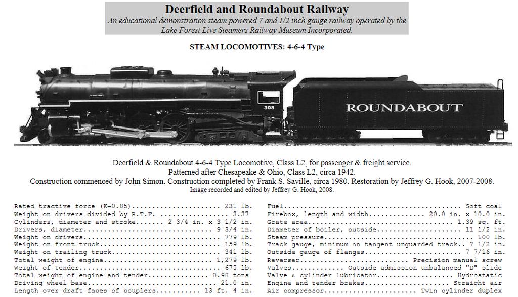
STEAM ENGINE C&O No. 308
 Deerfield and Roundabout Railway STEAM ENGINE C&O No. 308 Operational Information for Engineers September 2, 2018 4-6-4 Type Locomotive, for passenger & freight service. Patterned after Chesapeake & Ohio,
R10 Set No: 1 ''' ' '' '' '' Code No: R31033
 R10 Set No: 1 III B.Tech. I Semester Regular and Supplementary Examinations, December - 2013 DYNAMICS OF MACHINERY (Common to Mechanical Engineering and Automobile Engineering) Time: 3 Hours Max Marks:
10/29/2018. Chapter 16. Turning Moment Diagrams and Flywheel. Mohammad Suliman Abuhaiba, Ph.D., PE
 1 Chapter 16 Turning Moment Diagrams and Flywheel 2 Turning moment diagram (TMD) graphical representation of turning moment or crank-effort for various positions of the crank 3 Turning Moment Diagram for
Application Notes. Calculating Mechanical Power Requirements. P rot = T x W
 Application Notes Motor Calculations Calculating Mechanical Power Requirements Torque - Speed Curves Numerical Calculation Sample Calculation Thermal Calculations Motor Data Sheet Analysis Search Site
Components of Hydronic Systems
 Valve and Actuator Manual 977 Hydronic System Basics Section Engineering Bulletin H111 Issue Date 0789 Components of Hydronic Systems The performance of a hydronic system depends upon many factors. Because
The development of a differential for the improvement of traction control
 The development of a differential for the improvement of traction control S E CHOCHOLEK, BSME Gleason Corporation, Rochester, New York, United States of America SYNOPSIS: An introduction to the function
Simple Gears and Transmission
 Simple Gears and Transmission Simple Gears and Transmission page: of 4 How can transmissions be designed so that they provide the force, speed and direction required and how efficient will the design be?
III B.Tech I Semester Supplementary Examinations, May/June
 Set No. 1 III B.Tech I Semester Supplementary Examinations, May/June - 2015 1 a) Derive the expression for Gyroscopic Couple? b) A disc with radius of gyration of 60mm and a mass of 4kg is mounted centrally
Unit V HYDROSTATIC DRIVE AND ELECTRIC DRIVE
 Unit V HYDROSTATIC DRIVE AND ELECTRIC DRIVE HYDROSTATIC DRIVE In this type of drives a hydrostatic pump and a motor is used. The engine drives the pump and it generates hydrostatic pressure on the fluid.
White Paper: The Physics of Braking Systems
 White Paper: The Physics of Braking Systems The Conservation of Energy The braking system exists to convert the energy of a vehicle in motion into thermal energy, more commonly referred to as heat. From
AT 2303 AUTOMOTIVE POLLUTION AND CONTROL Automobile Engineering Question Bank
 AT 2303 AUTOMOTIVE POLLUTION AND CONTROL Automobile Engineering Question Bank UNIT I INTRODUCTION 1. What are the design considerations of a vehicle?(jun 2013) 2..Classify the various types of vehicles.
14 Single- Phase A.C. Motors I
 Lectures 14-15, Page 1 14 Single- Phase A.C. Motors I There exists a very large market for single-phase, fractional horsepower motors (up to about 1 kw) particularly for domestic use. Like many large volume
ME 466 PERFORMANCE OF ROAD VEHICLES 2016 Spring Homework 3 Assigned on Due date:
 PROBLEM 1 For the vehicle with the attached specifications and road test results a) Draw the tractive effort [N] versus velocity [kph] for each gear on the same plot. b) Draw the variation of total resistance
Fundamentals of steam turbine systems
 Principles of operation Fundamentals of steam turbine systems - The motive power in a steam turbine is obtained by the rate of change in momentum of a high velocity jet of steam impinging on a curved blade
B.TECH III Year I Semester (R09) Regular & Supplementary Examinations November 2012 DYNAMICS OF MACHINERY
 Regular & Supplementary Examinations November 2012 DYNAMICS OF MACHINERY") 1 B.TECH III Year I Semester (R09) Regular & Supplementary Examinations November 2012 DYNAMICS OF MACHINERY (Mechanical Engineering) Time: 3 hours Max. Marks: 70 Answer any FIVE questions All questions
1 B.TECH III Year I Semester (R09) Regular & Supplementary Examinations November 2012 DYNAMICS OF MACHINERY (Mechanical Engineering) Time: 3 hours Max. Marks: 70 Answer any FIVE questions All questions
Figure 1: Forces Are Equal When Both Their Magnitudes and Directions Are the Same
 Moving and Maneuvering 1 Cornerstone Electronics Technology and Robotics III (Notes primarily from Underwater Robotics Science Design and Fabrication, an excellent book for the design, fabrication, and
Golding's Horse Power Computer (1908)
") Golding's Horse Power Computer (1908) Stephan Weiss Since the beginning of the Industrial Revolution and on through progressive electrification the steam engine has been the main source for power. Engineers
Golding's Horse Power Computer (1908) Stephan Weiss Since the beginning of the Industrial Revolution and on through progressive electrification the steam engine has been the main source for power. Engineers
Planetary Roller Type Traction Drive Unit for Printing Machine
 TECHNICAL REPORT Planetary Roller Type Traction Drive Unit for Printing Machine A. KAWANO This paper describes the issues including the rotation unevenness, transmission torque and service life which should
Simple Gears and Transmission
 Simple Gears and Transmission Contents How can transmissions be designed so that they provide the force, speed and direction required and how efficient will the design be? Initial Problem Statement 2 Narrative
CHAPTER 6 GEARS CHAPTER LEARNING OBJECTIVES
 CHAPTER 6 GEARS CHAPTER LEARNING OBJECTIVES Upon completion of this chapter, you should be able to do the following: Compare the types of gears and their advantages. Did you ever take a clock apart to
Electric Motors and Drives
 EML 2322L MAE Design and Manufacturing Laboratory Electric Motors and Drives To calculate the peak power and torque produced by an electric motor, you will need to know the following: Motor supply voltage:
Seals Stretch Running Friction Friction Break-Out Friction. Build With The Best!
 squeeze, min. = 0.0035 with adverse tolerance build-up. If the O-ring is made in a compound that will shrink in the fluid, the minimum possible squeeze under adverse conditions then must be at least.076
Chapter 15. Inertia Forces in Reciprocating Parts
 Chapter 15 Inertia Forces in Reciprocating Parts 2 Approximate Analytical Method for Velocity and Acceleration of the Piston n = Ratio of length of ConRod to radius of crank = l/r 3 Approximate Analytical
Baldor Basics: Understanding Torque
 TECHNICAL Baldor Basics: Understanding Torque Edward Cowern, P.E. In the process of applying industrial drive products, we occasionally are misled into believing that we are applying horsepower. The real
Theory of Machines. CH-1: Fundamentals and type of Mechanisms
 CH-1: Fundamentals and type of Mechanisms 1. Define kinematic link and kinematic chain. 2. Enlist the types of constrained motion. Draw a label sketch of any one. 3. Define (1) Mechanism (2) Inversion
MECHANISMS. AUTHORS: Santiago Camblor y Pablo Rivas INDEX
 MECHANISMS AUTHORS: Santiago Camblor y Pablo Rivas INDEX 1 INTRODUCTION 2 LEVER 3 PULLEYS 4 BELT AND PULLEY SYSTEM 5 GEARS 6 GEARS WITH CHAIN 7 WORM GEAR 8 RACK AND PINION 9 SCREW AND NUT 10 CAM 11 ECCENTRIC
Analysis of Parametric Studies on the Impact of Piston Velocity Profile On the Performance of a Single Cylinder Diesel Engine
 IOSR Journal of Mechanical and Civil Engineering (IOSR-JMCE) e-issn: 2278-1684,p-ISSN: 2320-334X, Volume 12, Issue 2 Ver. II (Mar - Apr. 2015), PP 81-85 www.iosrjournals.org Analysis of Parametric Studies
Driver Driven. InputSpeed. Gears
 Gears Gears are toothed wheels designed to transmit rotary motion and power from one part of a mechanism to another. They are fitted to shafts with special devices called keys (or splines) that ensure
Chapter 15. Inertia Forces in Reciprocating Parts
 Chapter 15 Inertia Forces in Reciprocating Parts 2 Approximate Analytical Method for Velocity & Acceleration of the Piston n = Ratio of length of ConRod to radius of crank = l/r 3 Approximate Analytical
Module 4: Actuators. CDX Diesel Hydraulics. Terms and Definitions. Cylinder Actuators
 Terms and Definitions Cylinder Actuators Symbols for Actuators Terms and Definitions II Cylinders Providing Linear Motion Cylinders Providing Angular Motion Parts of Actuators Mounting of Actuators Seals
Racing Tires in Formula SAE Suspension Development
 The University of Western Ontario Department of Mechanical and Materials Engineering MME419 Mechanical Engineering Project MME499 Mechanical Engineering Design (Industrial) Racing Tires in Formula SAE
SOME FACTORS THAT INFLUENCE THE PERFORMANCE OF
 SOME FACTORS THAT INFLUENCE THE PERFORMANCE OF Authored By: Robert Pulford Jr. and Engineering Team Members Haydon Kerk Motion Solutions There are various parameters to consider when selecting a Rotary
The Mechanics of Tractor Implement Performance
 The Mechanics of Tractor Implement Performance Theory and Worked Examples R.H. Macmillan CHAPTER 2 TRACTOR MECHANICS Printed from: http://www.eprints.unimelb.edu.au CONTENTS 2.1 INTRODUCTION 2.1 2.2 IDEAL
Speed Limit on Railway Curves. (Use of SuperElevation on Railways)
") Speed Limit on Railway Curves (Use of SuperElevation on Railways) Introduction When a train rounds a curve, it has a tendency to want to travel in a straight direction and the track must resist this movement,
Speed Limit on Railway Curves (Use of SuperElevation on Railways) Introduction When a train rounds a curve, it has a tendency to want to travel in a straight direction and the track must resist this movement,
SHAFT ALIGNMENT FORWARD
 Service Application Manual SAM Chapter 630-76 Section 24 SHAFT ALIGNMENT FORWARD One of the basic problems of any installation is aligning couplings or shafts. Therefore, this section will endeavor to
Test Which component has the highest Energy Density? A. Accumulator. B. Battery. C. Capacitor. D. Spring.
 Test 1 1. Which statement is True? A. Pneumatic systems are more suitable than hydraulic systems to drive powerful machines. B. Mechanical systems transfer energy for longer distances than hydraulic systems.
Steam Car Developments and Steam Aviation
 c Steam Car Developments and Steam Aviation Vol. VIII FEBRUARY, 19 W No. 96 Progress Report on the Leslie Steam Car. Those of our readers who have been following' the Magazine since the October, 1937,
Chapter 7: DC Motors and Transmissions. 7.1: Basic Definitions and Concepts
 Chapter 7: DC Motors and Transmissions Electric motors are one of the most common types of actuators found in robotics. Using them effectively will allow your robot to take action based on the direction
The characteristics of each type of service are given in table 1 given below:
 Types of Railway Services There are three types of passenger services which traction system has to cater for namely Urban, Sub-urban and Main line services. 1. Urban or city service In this type of service
LEAD SCREWS 101 A BASIC GUIDE TO IMPLEMENTING A LEAD SCREW ASSEMBLY FOR ANY DESIGN
 LEAD SCREWS 101 A BASIC GUIDE TO IMPLEMENTING A LEAD SCREW ASSEMBLY FOR ANY DESIGN Released by: Keith Knight Kerk Products Division Haydon Kerk Motion Solutions Lead Screws 101: A Basic Guide to Implementing
CSDA Best Practice. Hi-Cycle Concrete Cutting Equipment. Effective Date: Oct 1, 2010 Revised Date:
 CSDA Best Practice Title: Hi-Cycle Concrete Cutting Equipment Issue No: CSDA-BP-010 : Oct 1, 2010 Revised : Introduction Hi-cycle/high frequency concrete cutting equipment has become more prevalent in
YASKAWA AC Drives. Compressor Applications Application Overview
 YASKAWA AC Drives Compressor Applications Application Overview This document provides a general application overview and is intended to familiarize the reader with the benefits of using AC drives in compressor
The Discussion of this exercise covers the following points:
 Exercise 3-3 Venturi Tubes EXERCISE OBJECTIVE In this exercise, you will study the relationship between the flow rate and the pressure drop produced by a venturi tube. You will describe the behavior of
Infinitely Variable Capacity Control
 Purdue University Purdue e-pubs International Compressor Engineering Conference School of Mechanical Engineering 1972 Infinitely Variable Capacity Control K. H. White Ingersoll-Rand Company Follow this
ENGINES ENGINE OPERATION
 ENGINES ENGINE OPERATION Because the most widely used piston engine is the four-stroke cycle type, it will be used as the example for this section, Engine Operation and as the basis for comparison in the
CHAPTER THREE DC MOTOR OVERVIEW AND MATHEMATICAL MODEL
 CHAPTER THREE DC MOTOR OVERVIEW AND MATHEMATICAL MODEL 3.1 Introduction Almost every mechanical movement that we see around us is accomplished by an electric motor. Electric machines are a means of converting
In order to discuss powerplants in any depth, it is essential to understand the concepts of POWER and TORQUE.
 -Power and Torque - ESSENTIAL CONCEPTS: Torque is measured; Power is calculated In order to discuss powerplants in any depth, it is essential to understand the concepts of POWER and TORQUE. HOWEVER, in
Moments. It doesn t fall because of the presence of a counter balance weight on the right-hand side. The boom is therefore balanced.
 Moments The crane in the image below looks unstable, as though it should topple over. There appears to be too much of the boom on the left-hand side of the tower. It doesn t fall because of the presence
The gear boxes can be run at the same speeds as the actuator models. Do not exceed torque ratings.
 1. What is the lifting torque required? The lifting torque for a single actuator depends on the load, the worm gear ratio, type of screw (machine cut or ball screw) and the pitch of the lifting screw.
13. APTA PR-E-RP Recommended Practice for Diesel Electric Passenger Locomotive Blended Brake Control
 13. APTA PR-E-RP-014-99 Recommended Practice for Diesel Electric Passenger Locomotive Blended Brake Control Approved March 4, 1999 APTA PRESS Task Force Authorized March 17, 1999 APTA Commuter Rail Executive
Development of Motor-Assisted Hybrid Traction System
 Development of -Assisted Hybrid Traction System 1 H. IHARA, H. KAKINUMA, I. SATO, T. INABA, K. ANADA, 2 M. MORIMOTO, Tetsuya ODA, S. KOBAYASHI, T. ONO, R. KARASAWA Hokkaido Railway Company, Sapporo, Japan
Mechanics and Mechanisms. What is do you think about when you hear the word mechanics? Mechanics. Is this a mechanism? 2/17/2011
 Mechanics and Mechanisms What is do you think about when you hear the word mechanics? Mechanics Mechanics is the study of how things move Is this a mechanism? Concerned with creating useful movement through
MECHANISM: TRANSMISSION THE TYPE OF INPUT MOVEMENT IS THE SAME AS THE OUTPUT TRANSFORMATION THE MECHANISM TRANSFORMS THE TYPE OF MOVEMENT
 MECHANISM: The mechanisms are elements intended to transmit and transform forces and movements from an INPUT element (motor) to an OUTPUT element. Types of movements: Rotary Motion -this is motion in a
6: Vehicle Performance
 6: Vehicle Performance 1. Resistance faced by the vehicle a. Air resistance It is resistance offered by air to the forward movement of vehicle. This resistance has an influence on performance, ride and
THROTTLE VALVE. The valve stem packing consists of closely fitting bushings suitable leak-off openings.
 Superseding I. B. 6166 Westinghouse StealTl Turbines-LB. 6166 (Rev. I) THROTTLE VALVE is valva is of the hydraulic type and is operated by oil (or other suitftble fluid). In a description, it can be divided
(12) Patent Application Publication (10) Pub. No.: US 2005/ A1
 Patent Application Publication (10) Pub. No.: US 2005/ A1") US 20050132699A1 (19) United States (12) Patent Application Publication (10) Pub. No.: US 2005/0132699 A1 Newman (43) Pub. Date: Jun. 23, 2005 (54) CONVERTNG PRESSURE ENERGY FROM Publication Classification
US 20050132699A1 (19) United States (12) Patent Application Publication (10) Pub. No.: US 2005/0132699 A1 Newman (43) Pub. Date: Jun. 23, 2005 (54) CONVERTNG PRESSURE ENERGY FROM Publication Classification
Richard Hull s Mysterious Motor
 Update June 2009: The following is some updated information regarding http://www.mtaonline.net/~hheffner/hullmotor.pdf fig. 3 provided below is an improved version of Fig. 3 in the above original work.
ESCONDIDO FIRE DEPT TRAINING MANUAL Section Driver Operator Page 1 of 13 Apparatus Power Plants Revised
 Driver Operator Page 1 of 13 DIESEL ENGINE FUNDAMENTALS A diesel engine is an internal combustion reciprocating piston engine that operates on liquid fuel. It converts the chemical energy of the fuel,
FEDERAL EXCISE TAXES (F.E.T.) CALCULATIONS
 CALCULATIONS") FEDERAL EXCISE TAXES (F.E.T.) CALCULATIONS Foreword: Trailers are normally designed to transport a particular type of cargo and, as a result of that design, are assigned a Gross Vehicle Weight Rating (GVWR)
FEDERAL EXCISE TAXES (F.E.T.) CALCULATIONS Foreword: Trailers are normally designed to transport a particular type of cargo and, as a result of that design, are assigned a Gross Vehicle Weight Rating (GVWR)
Special edition paper
 Special edition paper Adoption of Articulated Structure in AC Train Ryohei Shimamune*, Takahiro Kikuchi*, Hiroshi Nomoto* and Mitsuyuki Osawa* The AC Train that is destined to become the next-generation
WEEK 4 Dynamics of Machinery
 WEEK 4 Dynamics of Machinery References Theory of Machines and Mechanisms, J.J.Uicker, G.R.Pennock ve J.E. Shigley, 2003 Prof.Dr.Hasan ÖZTÜRK 1 DYNAMICS OF RECIPROCATING ENGINES Prof.Dr.Hasan ÖZTÜRK The
Angular Momentum Problems Challenge Problems
 Angular Momentum Problems Challenge Problems Problem 1: Toy Locomotive A toy locomotive of mass m L runs on a horizontal circular track of radius R and total mass m T. The track forms the rim of an otherwise
Module 6 Assignment Part A
 Module 6 Assignment Part A TOTAL MARKS Part A = 192 TOTAL QUESTIONS Part A = 36 Question 1 [3 Marks] What does pressure refer to in relation to hydrostatics and what is it dependent on? Question 2 [14
FAVOURABLE POINTS IN FOUR CYLINDER DESIGN LOCOMOTIVES.
 [No. 141] G.W.R. Mechanics Institute. SWINDON ENGINEERING SOCIETY. TRANSACTIONS, 1923-24. ORDI NARY M EETING January 3rd, 1924. Chairman Mr. O. E. F. Deverell. FAVOURABLE POINTS IN FOUR CYLINDER DESIGN
Laboratory Exercise 12 THERMAL EFFICIENCY
 Laboratory Exercise 12 THERMAL EFFICIENCY In part A of this experiment you will be calculating the actual efficiency of an engine and comparing the values to the Carnot efficiency (the maximum efficiency
AGN Unbalanced Loads
 Application Guidance Notes: Technical Information from Cummins Generator Technologies AGN 017 - Unbalanced Loads There will inevitably be some applications where a Generating Set is supplying power to
CHAPTER 1 BALANCING BALANCING OF ROTATING MASSES
 CHAPTER 1 BALANCING Dynamics of Machinery ( 2161901) 1. Attempt the following questions. I. Need of balancing II. Primary unbalanced force in reciprocating engine. III. Explain clearly the terms static
Design And Analysis Of A Camless Valve Mechanism For I.C Engines Using Rotary Disc Valves
 Design And Analysis Of A Camless Valve Mechanism For I.C Engines Using Rotary Disc Valves Vivek Jitendra Panchal, Nachiket Milind Chitnavis Abstract: It is the object of the presented paper to provide
The Mark Ortiz Automotive
 July 2004 WELCOME Mark Ortiz Automotive is a chassis consulting service primarily serving oval track and road racers. This newsletter is a free service intended to benefit racers and enthusiasts by offering
All levers are one of three types, usually called classes. The class of a lever depends on the relative position of the load, effort and fulcrum:
 Página 66 de 232 Mechanisms A mechanism is simply a device which takes an input motion and force, and outputs a different motion and force. The point of a mechanism is to make the job easier to do. The
Engine Power and Fueling Comparison Between Vessels with Conventional Transmissions and Controllable Speed Propeller Transmissions During Dynamic
 Engine Power and Fueling Comparison Between Vessels with Conventional Transmissions and Controllable Speed Propeller Transmissions During Dynamic Positioning Operation Prepared by: CSP Electronics Ray
Design/Modeling and Thermal Analysis on Cylinder Head of I.C Engine
 Design/Modeling and Thermal Analysis on Cylinder Head of I.C Engine G.Bahadur Vali Department of Mechanical, Chebrolu Engineering College. Abstract: A cylinder head is made of box type of section of considerable
FLUID POWER P&IDs. IDENTIFY the symbols used on engineering fluid power drawings for the following components:
 FLUID POWER P&IDs Fluid power diagrams and schematics require an independent review because they use a unique set of symbols and conventions. EO 1.11 IDENTIFY the symbols used on engineering fluid power
GRADE 7 TEKS ALIGNMENT CHART
 GRADE 7 TEKS ALIGNMENT CHART TEKS 7.2 extend previous knowledge of sets and subsets using a visual representation to describe relationships between sets of rational numbers. 7.3.A add, subtract, multiply,
SAMPLE STUDY MATERIAL
 IC Engine - ME GATE, IES, PSU 1 SAMPLE STUDY MATERIAL Mechanical Engineering ME Postal Correspondence Course Internal Combustion Engine GATE, IES & PSUs IC Engine - ME GATE, IES, PSU 2 C O N T E N T 1.
Application of ABAQUS to Analyzing Shrink Fitting Process of Semi Built-up Type Marine Engine Crankshaft
 Application of ABAQUS to Analyzing Shrink Fitting Process of Semi Built-up Type Marine Engine Crankshaft Jae-Cheol Kim, Dong-Kwon Kim, Young-Duk Kim, and Dong-Young Kim System Technology Research Team,
SNS COLLEGE OF TECHNOLOGY (An Autonomous Institution) Department of Automobile Engineering
 Department of Automobile Engineering") SNS COLLEGE OF TECHNOLOGY (An Autonomous Institution) Department of Automobile Engineering ACADEMIC YEAR 2015-16 FIFTH SEMESTER AU 302 AUTOMOTIVE ENGINE COMPONENTS DESIGN UNIT 2 CYLINDER, PISTON & CONNECTING
SNS COLLEGE OF TECHNOLOGY (An Autonomous Institution) Department of Automobile Engineering ACADEMIC YEAR 2015-16 FIFTH SEMESTER AU 302 AUTOMOTIVE ENGINE COMPONENTS DESIGN UNIT 2 CYLINDER, PISTON & CONNECTING
Additional examination-style questions
 1 Figure 1 shows a remote-control camera used in space for inspecting space stations. The camera can be moved into position and rotated by firing thrusters which eject xenon gas at high speed. The camera
CYCLICALLY OPERATING VALVES FOR MACHINES OR ENGINES (valves in general F16K)
") F01L CYCLICALLY OPERATING VALVES FOR MACHINES OR ENGINES (valves in general F16K) Valve-gear or valve arrangements, e.g. lift-valve gear; Lift-valve, i.e. cut-off apparatus with closure members having
F01L CYCLICALLY OPERATING VALVES FOR MACHINES OR ENGINES (valves in general F16K) Valve-gear or valve arrangements, e.g. lift-valve gear; Lift-valve, i.e. cut-off apparatus with closure members having
Variable Speed Drives
 -1 Why Vary Speed? Variable speed drives are needed because many applications are not run at the same speed all of the time, due to the surrounding conditions. Revolutions per minute (RPM) of the driven
Motor Type Selection. maxon s EC 4-pole brushless motors
 Motor Type Selection Parameters that define a motor type are the mechanical output power, the shaft bearing system, the commutation system used, and the possible combinations with gearheads and sensors.
FRICTION DEVICES: DYNAMOMETER. Presented by: RONAK D. SONI Assistant Professor Parul Institute of Technology, Parul University
 FRICTION DEVICES: DYNAMOMETER Presented by: RONAK D. SONI Assistant Professor Parul Institute of Technology, Parul University DYNAMOMETER A dynamometer is a brake but in addition it has a device to measure
Application Note Original Instructions Development of Gas Fuel Control Systems for Dry Low NOx (DLN) Aero-Derivative Gas Turbines
 Aero-Derivative Gas Turbines") Application Note 83404 Original Instructions Development of Gas Fuel Control Systems for Dry Low NOx (DLN) Aero-Derivative Gas Turbines Woodward reserves the right to update any portion of this publication
Application Note 83404 Original Instructions Development of Gas Fuel Control Systems for Dry Low NOx (DLN) Aero-Derivative Gas Turbines Woodward reserves the right to update any portion of this publication
FRONTAL OFF SET COLLISION
 FRONTAL OFF SET COLLISION MARC1 SOLUTIONS Rudy Limpert Short Paper PCB2 2014 www.pcbrakeinc.com 1 1.0. Introduction A crash-test-on- paper is an analysis using the forward method where impact conditions
Step Motor Lower-Loss Technology An Update
 Step Motor Lower-Loss Technology An Update Yatsuo Sato, Oriental Motor Management Summary The demand for stepping motors with high efficiency and low losses has been increasing right along with the existing
2 Technical Background
 2 Technical Background Vibration In order to understand some of the most difficult R- 2800 development issues, we must first briefly digress for a quick vibration tutorial. The literature concerning engine
LESSON Transmission of Power Introduction
 LESSON 3 3.0 Transmission of Power 3.0.1 Introduction Earlier in our previous course units in Agricultural and Biosystems Engineering, we introduced ourselves to the concept of support and process systems
The Effect of Spring Pressure on Carbon Brush Wear Rate
 The Effect of Spring Pressure on Carbon Brush Wear Rate By Jeff D. Koenitzer, P.E. Milwaukee, Wisconsin, USA Preface 2008 For decades there was extensive testing of countless different carbon brush contact
Development of Rattle Noise Analysis Technology for Column Type Electric Power Steering Systems
 TECHNICAL REPORT Development of Rattle Noise Analysis Technology for Column Type Electric Power Steering Systems S. NISHIMURA S. ABE The backlash adjustment mechanism for reduction gears adopted in electric
Fabric Pulse Jet Collector Early Designs (Circa 1963)
") Fabric Pulse Jet Collector Early Designs (Circa 1963) To expand in the application area for process streams that operate at higher temperatures and corrosive conditions, an improved fabric pulse jet collector
Fabric Pulse Jet Collector Early Designs (Circa 1963) To expand in the application area for process streams that operate at higher temperatures and corrosive conditions, an improved fabric pulse jet collector
Carburetor Instructions
 Carburetor Instructions for HUDSON SUPER SIX ESSEX SIX CYLINDER Hudson Motor Car Co. DETROIT, U.S.A. Carburetor The carburetor is a device for metering correct amounts of fuel and air for the various
Hours / 100 Marks Seat No.
 17412 16117 3 Hours / 100 Seat No. Instructions (1) All Questions are Compulsory. (2) Answer each next main Question on a new page. (3) Illustrate your answers with neat sketches wherever necessary. (4)
Code No: R Set No. 1
 Code No: R05310304 Set No. 1 III B.Tech I Semester Regular Examinations, November 2007 KINEMATICS OF MACHINERY ( Common to Mechanical Engineering, Mechatronics, Production Engineering and Automobile Engineering)
Theory of Machines II EngM323 Laboratory User's manual Version I
 Theory of Machines II EngM323 Laboratory User's manual Version I Table of Contents Experiment /Test No.(1)... 2 Experiment /Test No.(2)... 6 Experiment /Test No.(3)... 12 EngM323 Theory of Machines II
Assignment 4:Rail Analysis and Stopping/Passing Distances
 CEE 3604: Introduction to Transportation Engineering Fall 2011 Date Due: September 26, 2011 Assignment 4:Rail Analysis and Stopping/Passing Distances Instructor: Trani Problem 1 The basic resistance of
SpiritPFC Torque/Horsepower Comparison Dynamometer Test Date: 5/7/2006
 SpiritPFC / Comparison Dynamometer Test Date: 5/7/2006 Dynamometer Test Outline: Contained within this document you will find data collected using a Dyno Datamite engine dynamometer hardware and software
Daniel. Liquid Control Valves Technical Guide. Technical Guide DAN-LIQ-TG-44-rev0813. DAN-LIQ-TG-44-rev0208. February 2008.
 DAN-LIQ-TG-44-rev0208 February 2008 Daniel Liquid Control Valves Technical Guide www.daniel.com Daniel Measurement and Control Theory, Principle of Operation and Applications This brochure has been prepared
The Differential Hydro-Mechanical Variator
 Contemporary Engineering Sciences, Vol. 8, 2015, no. 4, 191-196 HIKARI Ltd, www.m-hikari.com http://dx.doi.org/10.12988/ces.2015.514 The Differential Hydro-Mechanical Variator Ildar Ilgizarovich Salakhov
Control of Heat Processes
 PG 30 kwietnia 2011 Slide 1 of 66 Turbine power PG test P = m ṁ 0 H η i η m η g m coefficient which takes into account extraction flows Slide 2 of 66 Turbine regulation PG 1. Quantative adjustment varied
Air Brakes From Real Trains
 Air Brakes From Real Trains Real Trains has been producing air brake systems for our 1 1/2 scale trucks for more than seventeen years. In this time over 100 pairs of trucks equipped with air brakes have