Variable Speed Drives
|
|
|
- Gervais Nichols
- 5 years ago
- Views:
Transcription
1 -1
 of the driven shaft need to be increased or decreased when there are changes in load conditions, application requirements, or other circumstances.")


2 Why Vary Speed? Variable speed drives are needed because many applications are not run at the same speed all of the time, due to the surrounding conditions. Revolutions per minute (RPM) of the driven shaft need to be increased or decreased when there are changes in load conditions, application requirements, or other circumstances. Variable speed belt drives achieve the versatility needed to maximize application efficiency and productivity while remaining an inexpensive solution. In the most typical installation, a belt connects a variable speed pulley to a driven sheave. The pulley is mounted on a motor shaft and the motor is at constant speed. Thus, the speed at the driven shaft is a ratio of the pitch diameters of the pulley and sheave. Overview For this catalog, Lovejoy terminology will refer to any variable pitch pulley as a pulley and to any non-variable pulley as a sheave, driven sheave, or companion sheave. The RPM at the driven shaft is found by the following simple equation: ND = Nd x d/d Where ND is the RPM at the driven shaft Nd is the RPM of the driving shaft d is the pitch diameter of the driver D is the pitch diameter of the driven Since Nd is always a fixed RPM, it can then be seen that by changing the pitch diameter of either d or D, the driven RPM will change. Common Mounting Methods 1) Adjustable Center Drives This type of belt drive consists of one pulley and one sheave. The pulley is spring-loaded and is usually mounted on the driver shaft. The driver is most often an electric motor which is mounted on an adjustable motor base that can be moved toward or away from the driven sheave. The springs in the pulley take up any slack in the belt when an adjustment is made. When the base is adjusted, moving the pulley toward the sheave, the RPM at the sheave increases. Likewise, when the base is adjusted away from the sheave, the RPM at the sheave decreases. In the photo at right (Adjustable Center V-V Drive), the drive is at its maximum speed position. This is called a V-V drive because the driven sheave is grooved. The pulley is called two-side moveable because it has two springs (one against each flange) and two moveable flanges. ADJUSTABLE CENTER V-V DRIVE Notice that the belt in the pulley is at the maximum pitch diameter, or d as mentioned in the previous equation. As the base is adjusted away from the sheave, d will decrease and the driven speed, ND, will decrease proportionately. The photos at right (Adjustable Center V-Flat Drive Max. Speed Position and Adjustable Center V-Flat Drive Min. Speed Position) show a V-Flat drive, so called because the driven sheave is flat, not grooved. The pulley is called a one-side moveable type because it has only one spring and one moveable flange. ADJUSTABLE CENTER V-FLAT DRIVE MAX. SPEED POSITION Note that in the Adjustable Center V-Flat Max. Speed Position figure, the drive is at the maximum speed position, with the variable speed pulley flanges closed together and the belt at the maximum pitch diameter. As the motor base is adjusted to increase the center distance between the motor and the driven shaft, the moveable flange on the variable speed pulley opens to allow the belt to run at a smaller pitch diameter (Adjustable Center V-Flat Drive Min. Speed Position). -2! WARNING You must refer to page iv for Important Safety Instructions and Precautions for the selection and use of these products. Failure to follow the instructions and precautions can result in severe injury or death. ADJUSTABLE CENTER V-FLAT DRIVE MIN. SPEED POSITION


3 Overview Note that the axial position of the belt on the flat-faced companion sheave changes as the drive moves through the speed range. This illustrates the need for a flat-faced companion sheave when using a wide variable speed belt and a one-side moveable variable speed pulley. The Adjustable Center Angle Mount Drive figure shows a more unusual mounting, with a one-side moveable pulley driving a grooved sheave. The motor base must be offset at an angle to keep the belt in line. A typical Lovejoy adjustable center drive will have a speed ratio that is, the range of speed at the driven sheave from 1.6 to 1 up to 3.8 to 1. For example, with the right combination of pulley and sheave, you can attain a speed range at the driven sheave of 1,800 to 600 RPM, 3 to 1 speed ratio. ADJUSTABLE CENTER ANGLE MOUNT DRIVE An alternate mounting method may be used when the spring-loaded pulley is mounted on the driven shaft, with the companion sheave mounted on the driver shaft. With this arrangement, the horsepower at the driven shaft is constant through most of the speed range, but the torque decreases in proportion to the pitch diameter of the belt in the spring-loaded pulley. Caution must be taken not to overspeed the driven variable speed pulley beyond 10,500 FPM (feet per minute) rim speed. 2) Fixed Center Drives This method of mounting requires no change in center distance between the driver and driven units. Because the shaft center-to-center distance does not change, this is called a fixed center drive. The usual arrangement has one pulley, the driver, which is mechanically adjustable. The adjustable pulley flanges are opened or closed mechanically, usually with a handwheel on the end of the pulley. The other pulley is spring-loaded and compensates for belt slack when the adjustable pulley is actuated. FIXED CENTER DRIVE Horsepower vs. Adjustable center drives with the spring-loaded pulley as the driver are constant torque drives. That is, for each variable speed pulley and companion sheave combination, the torque at the sheave is constant. Horsepower decreases in proportion to RPM at the driven sheave. When the adjustable driver pulley is fully opened, the belt is at its minimum pitch diameter. At the same time, the spring-loaded driven pulley is fully closed with the belt at its maximum pitch diameter. This results in the slowest possible driven speed. As the adjustable pulley flanges are closed together, the driver pulley pitch diameter increases while at the same time the spring-loaded pulley is forced by the drive belt to open. This results in a smaller pitch diameter at the driven member. The driven speed then increases until the adjustable pulley is fully closed and the spring-loaded pulley is fully open (the maximum speed position). Speed change must always take place while the motor is running. The Fixed Center Drive figure shows a typical arrangement, with the adjustable pulley at minimum pitch diameter and the spring-loaded pulley at maximum pitch diameter. This is the minimum speed position. Fixed center drives are constant torque from minimum speed to driver speed and constant horsepower from driver speed to maximum speed. Notes: 1. All Lovejoy pulleys and sheaves are balanced for operation at 1750 RPM. Balancing for higher speed operation is available consult our Engineering Department. 2. Lovejoy variable speed pulleys are bored to fit standard NEMA motor shafts. Consult our Customer Service Department for availability of non-standard and metric bores. Fixed center drives are used where space is limited and/or where a wider speed range is needed. They are sometimes called compound drives because the ratio of the two pulleys is compounded, resulting in a greater available driven speed range. Speed ratios up to 11.5 to 1 are possible, but this is not necessarily in the form of a speed decrease. For example, with a 1,750 RPM motor and a Lovejoy HM-3/31901 drive package, the output speed at the driven pulley could be as high as 4,850 RPM. -3
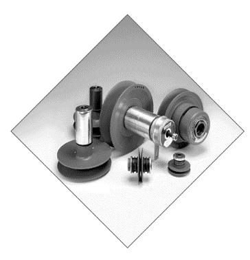
4 Overview Variable Speed Pulley Product Preview Lovejoy offers the most complete line of non-enclosed variable speed belt drives from fractional through 30 horsepower. Each component is made with the quality and reliability that Lovejoy builds into all of its power transmission products. Variable speed pulleys offer several benefits: n Very economical and reliable method of speed change. n Allows the user to find the ideal speed without changing sheaves and belts. This is especially important on applications where final driven speed is critical and difficult to attain with two fixed-diameter sheaves. Speed range within the ratio is infinite, and speed change is accomplished quickly, while the drive is running. n Can be used as a highly efficient belt tensioner, with no adjustment necessary. n Offers a form of soft start, eliminating belt slip and premature wear on belt drives with inherent high torque start-up requirements. Econoline Series The Econoline Pulley series provides reliable variable speed service with a proven design at an economical cost. Consisting of a wide selection of models, the Econoline series is ideal for both adjustable and fixed center drives using classic A and B (or 4L and 5L) section drive belts. This series also offers: driven speed ratios from 1.6 to 1 up to 2.7 to 1 and horsepower ranges from fractional through 5 1,750 RPM motor speed. ECONOLINE SERIES ALUMINOLINE SERIES The flanges are constructed of durable cast iron.typical applications of this maintenance-free pulley include: conveyors, mixers, small machine tools, mower traction drives, printing equipment, packaging machines, and belt tensioners. New in this catalog edition A two-side moveable Econoline version has been added in three sizes: five-inch, six-inch and seven-inch. These new models are ideal in applications where belt alignment is critical. Aluminoline Series Aluminoline variable speed pulleys offer the best possible belt alignment with the least amount of overhung load. Used with A and B drive belts, these pulleys not only have anodized aluminum flanges which provide quiet operation with minimum vibration, but are rated for 1 / 3 through 1 1 / 2 HP motors. These two-side moveable pulleys offer greater speed ratios (up to 2.75 to 1). Due to the corrosion-resistant properties of these pulleys, they are ideal for use on agricultural machinery, food packaging and bottling equipment, baseball pitching machines, and a variety of other products. -4

5 Overview WB Series Pulleys in the WB series use wide variable speed belts for the most efficient transmission of torque through the widest possible speed range. This twoside moveable pulley series offers the best possible belt alignment when used with a grooved companion sheave. WB pulleys provide maximum service when lubricated through a convenient grease fitting and offer sizes ranging from 6 to 13 inches in diameter, with the largest model capable of 15 HP. All models greater than 1 HP feature durable cast iron flanges (Models 245 and 260 are made with lightweight, corrosion-resistant anodized aluminum flanges). WB SERIES These pulleys can be used on both adjustable and fixed center drives. Typical applications include: conveyors, printing presses, mixers, packaging and bottle-filling machines, machine tools, and agricultural equipment. Hi-Ratio Series Hi-Ratio drives provide the unique combination of broader driven speed ranges and lowest possible minimum driven speed. Three drive packages are available, with horsepower ranges from 1 / 2 to 5, with a 1,750 RPM motor, and speed ratios up to 11.5 to 1. They are ideal for use on machine tools and mixing machinery. Hexadrive Series Hexadrive pulleys are the most durable variable speed pulleys available. The hexagon-shaped center shaft efficiently transmits torque through the six hex flats for top performance and long life. The surface of the shaft is covered with a resilient elastomer, which means there is no metal-to-metal contact on any sliding surface and lubrication is not necessary. HI-RATIO SERIES These pulleys are available in adjustable or fixed center drives and come in two styles: one-side moveable for V-Flat drives, and two-side moveable for V-V drives. Flanges are made of cast iron to provide a long-wearing belt contact area. These pulleys provide size ranges from 6 up to 12.5 in diameter, and a maximum rating of 30 1,750 RPM. Some typical applications include: agricultural equipment, food packaging machines, air handling systems, textile spinning frames, mixers, pumps, machine tools, and foundry snag grinders. Adjusta-Sheave Series The Lovejoy Adjusta-Sheave can be a cost-saving alternative to a springloaded pulley when speed change is infrequent. To change speeds, the drive must be shut down (unlike other variable speed pulleys). All models use wide variable speed belts. The Adjusta-Sheave design eliminates the need for internal drive keys, thus providing more efficient transfer of power and longer life. The two cast iron flanges are moveable, allowing perfect belt alignment at all times. Four models are available with ranges from 5 through 30 HP and speed ratios up to 2.5 to 1. Typical applications include: textile spinning frames, heating and air conditioning equipment, pumps, etc. HEXADRIVE SERIES ADJUSTA-SHEAVE SERIES -5
6 Factors to Consider and Horsepower: Variable speed drives with constant torque loads can usually be selected by matching the variable speed pulley rating to that of the driver. Drive selection begins by matching the HP ratings, but final selection is based on torque, HP and RPM at the driven sheave. The application charts in this catalog specify driven speeds and torque ratings at the driven sheave for each pulley/sheave combination. Driven Speed Range (Ratio): As a general rule, an adjustable center drive can attain a maximum driven speed ratio of 3 to 1. Most fixed center drives can attain ratios as high as 8 to 1, but part of the driven speed range is faster than the motor speed. In all cases, pulleys that use variable speed belts will provide greater speed range than those using A or B belts. Space: In some cases the amount of available space will determine the size of the pulley and whether to use an adjustable or fixed center drive. Maintenance: Econoline and Hexadrive pulleys are virtually maintenance-free. They do not require lubrication or frequent speed change. Aluminoline and WB pulleys require lubrication and occasional cycling through the speed range for best results. Selection Process Retrofit: When replacing a variable speed pulley made by another manufacturer, it is important to select a Lovejoy pulley that is the same style, uses the same size belt and is as close as possible to the same diameter. The Quick Reference List on -10 provides this information at a glance. If you need help with a pulley interchange, call our Customer Service Department. Belt Selection: Wide variable speed belts offer several advantages over stock A and B (or 4L and 5L) belts and should be considered for all variable speed pulley drives. Variable speed belts are designed to operate over small pitch diameters, offer a broader speed range and form themselves to the pulley faces at all speeds. Shaft Sizes: Lovejoy variable speed pulleys are bored to fit standard NEMA motor shafts. The bore range for each model corresponds to its horsepower rating. Consult our Customer Service Department for availability of nonstandard and metric bores. Companion sheaves are bored for QD bushings for ease of installation, optimum performance, and availability of product. Steps in Selecting an Adjustable Center Belt Drive There are two common selection processes; one is for designing an entire drive package, the other to select a replacement component part of an existing drive, such as the variable speed pulley. It is important to understand the complete drive selection process in order to do either. First, review the factors to consider and the selection examples on pages -8 and -9 of the catalog. Then follow these procedures: Step 2: Step 3: Detailed drive selection data can be found on pages associated with the pulley that has been selected. Be sure the bore capacity of the pulley is suitable for your application. Refer to the Application chart that applies to the pulley you have chosen and select a companion sheave that suits the driven speed requirement. If more than one sheave will provide the correct speed range, select the largest one possible. This will provide the greatest amount of torque. (Lovejoy only supplies companion sheaves for wide variable speed belts.) You will also need to check the correct QD style bushing, bored to the driven shaft size to fit the sheave (see page SF-15). With the Econoline and Aluminoline series, the selection chart merely indicates the pitch diameter of the sheave you need to use. TYPICAL ADJUSTABLE CENTER DRIVE Designing a Complete Drive Package Step 1: Match the variable speed pulley with the motor horsepower and speed, but consider the torque and HP required at the driven shaft at all speeds. If actual torque and HP requirements are not known, rely on the fact that variable speed pulley ratings are compatible with the torque of the driver. Apply a service factor if needed. Step 4: Use the selection chart for the pulley/sheave combination you have chosen to find the distance between motor shaft and driven shaft (center distance) that is nearest your requirement. This will be the center distance at maximum speed position, or the point at which the motor shaft and driven shaft are closest together. Space must be provided in the machine to allow the center distance to be increased enough to attain the complete speed range. When you have found the center distance in the chart, read up or across to select the correct drive belt. Lovejoy only supplies variable speed belts.) With the Econoline and Aluminoline pulley series, our selection charts will specify the pitch length of the correct V-belt to use. -6
7 Selection Process Step 5: Select a suitable motor base from the catalog page for the pulley you have selected, or by reviewing the information on pages -60 through VSC-62.You will need to know the NEMA motor frame size for this step. For a complete adjustable center drive package, you will need a variable speed pulley, an adjustable motor base, a companion sheave with a QD bushing, and a drive belt. Be sure to specify the bore sizes for the variable speed pulley and the QD bushing (see page SF-15). Replacing a Drive Component Please keep the above steps in mind, even though they won t all apply. Replacing a Variable Speed Pulley Step 1: Use the Quick Reference List on page -10 and -11 to narrow down your choices based on the information you have. For example, if you know the pulley diameter and belt size, check the appropriate columns in the list and pick out all models that match. Step 2: Check the dimensional and performance details from the appropriate catalog page for the models you selected to find the best choice. In all replacement decisions, it is very important to consider the pulley style 1, 2, or 3 (see page -10) to get the best possible fit to the existing drive. Do NOT try to use a Lovejoy variable speed pulley with a belt that is not designed to drive. You will not attain the advertised speed range, and you may experience premature wear. Replacing a Companion Sheave Step 1: For a grooved sheave, determine the outside diameter of the sheave and the belt size. For a flat-faced sheave, measure the outside diameter and the face width. Step 2: Step 3: Select the correct base from the catalog pages -60 through -62. If it is NOT a Lovejoy base that is being replaced, be aware that the base mounting bolt locations may not match, and new holes may need to be drilled to mount the Lovejoy base to the machine. Check overall dimensions to be sure the base will fit the allotted space. Selecting a Fixed Center Belt Drive To select a fixed center package, it is necessary to know the following information: Horsepower and RPM of driver unit. Required speed range at the driven shaft. requirement at the driven shaft. Shaft center-to-center distance. Driver AND driven shaft sizes. The relationship between driver and driven shafts (C vs. Z mount). Refer to the drawing below. Lovejoy makes four types of fixed center drives: Econoline, WB, Hexadrive, and Hi-Ratio. The proper series to use depends on the horsepower rating, the required speed range, and the belt preference, as well as space and economic considerations. Once you have the information listed above and have selected the appropriate series, use the following procedure: Step 1: Step 2: Using the horsepower, driver speed, and required driven speed range information from above, select the appropriate series from Econoline, WB, Hi-Ratio, or Hexadrive. Select the correct manual driver pulley by choosing the model that is rated for your motor HP and speed. Be sure the pulley comes with a bore size that fits your motor shaft. Contact Lovejoy Customer Service for the availability of non-standard bores. Step 2: Step 3: Select the correct sheave from catalog pages -63 and -64. Replace the QD bushing (see page SF-15). Replacing an Adjustable Base Step 1: Determine the NEMA motor frame size or motor foot-mount dimensions. Step 3: Using the application chart for the pulley you have selected, choose a driven spring-loaded pulley that will handle the HP and torque requirement. Note that all Lovejoy fixed center drives are rated as constant horsepower from the base speed (motor speed) to the maximum driven speed. They are constant torque drives from base speed down to minimum driven speed. The ratings shown are those at the driven pulley. TYPICAL FIXED CENTER DRIVE C AND Z MOUNTING -7
8 Selection Process IMPORTANT: Be sure to specify the correct driven pulley for the mounting arrangement. For example, you need to specify an R suffix (for reverse mount) with the Econoline Series spring-loaded pulley if it is a C mount. Also check to be sure the driven pulley is available in the bore size that will fit the driven shaft. Step 4: Using the shaft center-to-center distance from d, select the correct drive belt from the Selection Chart. The center distance between the shafts must be held to the correct distance for the drive belt that is used in order to attain the published speed range. Drive belts are available only in certain lengths, so the center distance may need to be altered from the original design in order to suit the best available belt. If you have a center distance that is not shown in the chart, refer to the formulas in the Variable Speed Engineering Data on page -66, or call Lovejoy Engineering for assistance in calculating the correct center distance. Step 4: Step 5: From the Belt Selection chart, under the column headed by the 1922G8SK sheave, read down to find the center distance, then follow to the left to find the appropriate drive belt. The center distance nearest to 15 in the chart is Notice that the motor travel for full speed range with the 301E pulley is 3.5, so the maximum center distance will be about 19. Select a suitable motor base based on the NEMA motor frame size. For a 145T frame, there are two choices: the Model 301 cast iron base, or the Model SMB-184 steel base. Step 5: Specify the Lovejoy Model 501 Arm Bracket to prevent rotation of the manual pulley handwheel so that it can be adjusted while the motor is running. This item is NOT required for MLA or HLA driver pulleys. Step 6: For remote control or linear actuation of the manual pulley, refer to the appropriate section in the Econoline (MLA), Hi-Ratio, or Hexadrive (HEC, HLA) section of this catalog. Selection Examples: Adjustable Center Drives WB Series Selection Example A belt conveyor application requires a drive with a 2.8 to 1 speed ratio. The drive will consist of a variable speed belt drive, a speed reducer, and a chain drive from the reducer to the conveyor head pulley. The input speed range to the reducer must range from 370 to 1,050 RPM. The motor is 1 1,150 RPM, with a NEMA 145T frame and 7 / 8 shaft. The torque into the reducer must be 50 in-lb. Center distance between the motor shaft and the reducer input shaft is about 15. After assembling a complete drive package, you will end up five components: a 301E x 7 / 8 variable speed pulley; a 1922G8SK companion sheave; an SK bushing with a bore to fit the driven shaft; a 1922V544 belt; and a 301 or SMB-184 motor base. Aluminoline Selection Example A variable speed pulley is needed for use on a plastic cut-off machine that indexes material through a guillotine-type shear once every second. Inertia of the shear is not high, but the load is pulsating up to 25% over the motor torque. The motor is rated 1 / 2 1,750 RPM with a NEMA 56 frame ( 5 / 8 shaft), and a stock ( A or B section) belt is preferred. Good alignment and short center distance is a concern. The driven speed range requirement is 800 to 1,600 RPM. Step 1: Step 2: Step 3: The WB series is chosen to fit into existing motor belt guards and motor mounts (see page -28). For 1 1,150 RPM, the Model 301E variable speed driver pulley with a 7 / 8 bore (to fit the motor shaft) is selected. From the Driven Sheave Selection chart for the Model 301E pulley, the 1922G8SK should be used because it offers a driven speed range of 360 to 1,075 RPM, which covers the requirement for this drive. Note that the torque rating for this drive 58 in-lb. This is a constant torque output throughout the driven speed range. An SK bushing is needed to attach the companion sheave to the driven shaft. Step 1: Step 2: Referring to the Service Factor chart on page -66, a service factor of 1.3 is recommended for pulsating loads. horsepower multiplied by the service factor equals a drive load of 0.65 HP. Either the Econoline of Aluminoline series could be used with an A or B section belt, but in this case the Aluminoline is better because it is two-side moveable and will maintain better belt alignment with a short center distance. Both the Models 160 and 170 variable speed pulley are rated for 3 /4 HP, which is closest to the drive load of In our example, the motor shaft is 5 / 8, so we can use the Model
9 Selection Process Step 3: Step 4:. Step 5: The Driven Sheave Selection chart for the Model 160 variable speed driver pulley (see page -24) shows that a 6-inch pitch diameter companion sheave will provide a driven speed range of 615 to 1,675 RPM when used with a 1,750 RPM motor. This covers the required driven speed range. The belt selection chart shows 7.9 as the minimum distance for a 160 pulley and a 6 sheave. Moving across to the left in that chart, the belt for that center distance is an A33.You can see that the Model 160 pulley requires 2.7 travel to achieve full speed range, so the maximum center distance will be 7.9 (minimum cd) + 2.7, or 10.6 A suitable motor base must be selected based on the NEMA motor frame size. For a 56 frame motor, there are several choices: the Model 48/56 economy base, the Model 200 tilting base, the SMB-143 steel sliding base, or on of the two cast iron bases, and 135. Step 2: Step 3: The HM-30 driver is selected, and based on the motor HP, speed, and C mounting configuration, the Model driven pulley is most suitable. This drive is rated at 10 HP from 1,750 to 3,300 RPM driven speed, which is nearest to our 8 HP driven requirement. The Driven Speed chart shows that, with a 1,750 RPM motor, this drive will provide a range of 640 to 3,200 RPM at the pump. A check of stock bore sizes shows that the HM-30 is available in 1 3 / 8 (the motor shaft size), and the driven pulley is available with a 1 5 / 8 stock bore To select a drive belt, refer to the Belt Selection chart for the HM-30 drive. The 4430V600 belt is chosen because it is closest to the 16 1 / 2 center distance requirement. As the Belt Selection chart shows, the actual center distance is Important When the driven speed range is critical, it is necessary to set up the drive at the exact center distance specified for the belt selected. Any variation from the correct center distance will result in a driven speed range that is different from that shown in the drive selection charts. After assembling the complete drive package, you will end up with four components: a 160 x 5 / 8 variable speed pulley; a 6 pd companion sheave for an A belt with a bore to fit the driven shaft (not supplied by Lovejoy); an A33 drive belt (not supplied by Lovejoy); and a 48/56, 200, SMB-143, , or 135 motor base. Selection Example: Fixed Center Drive Hexadrive Series Selection Example A fixed center variable speed drive is needed for a centrifugal pump that has an 8 HP peak at 2,000 RPM. The motor is rated for 10 1,750 RPM, with a 1 3 / 8 shaft. The pump shaft is 1 5 / 8. Shaft center-to-center distance is approximately 16 1 / 2. There is no room to accommodate an adjustable base or to move the motor back and forth for speed adjustment, so a fixed center drive is preferred. shaft and driven shaft both are oriented in the same direction, so this is a C drive configuration. The service factor for a centrifugal pump is 1.0 (see page -66). Step 4: A Model 501 torque arm bracket is required to prevent rotation of the driver pulley handwheel and allow speed adjustment while the motor is running. If a remote control or linear actuated drive is preferred, the same basic package can be used, but the driver pulley will be a Model HEC-30 for electric remote control (also order the CH-2601 control station) or a Model HEC-30 for electric remote control (also order the CH-2601 control station) or a Model HLA-30 for linear actuation. For details on these pulleys, refer to pages -57 and -58. The 501 torque arm bracket is not necessary when using the HLA pulley. After assembling the complete drive package, you will end up with four components: an HM-30 x 3 / 8 manual driver speed pulley; a x 5 / 8 spring loaded driven pulley; a 4430V600 belt; and a 501 torque arm bracket. Step 1: The Hexadrive is selected because of the horsepower requirement. Fixed center drives are rated as constant HP drives from base (motor) speed to maximum driven speed. According to the ratings for 1,750 RPM motors, the drive package most suitable for this 8 HP requirement is a 10 HP drive. Refer to the drive selection data on page -56 for a 10 HP drive. -9
10 Selection Quick Reference List Adjustable Center Drives Pulley RPM Model Page Max. Belt Weight 1,750 1,150 Ratio Style OD OAL L Series lbs 1 /3 1 / A 2 1 /2 1 / A 2 1 /2 1 / A 2 1 /2 1 /3 5005A A 4 1 /2 1 / B 4 1 /2 1 / A 2 1 /2 1 / V 3 3 /4 1 / A 2 3 /4 1 / A 2 3 /4 1 / A 3 3 /4 1 / A or B 4 3 /4 1 / V 3 1 /2, 3 / 4 1 /3, 1 / V 5 1 /2, 3 / 4 1 /3, 1 / V / A /4 5010A A / B / B / B / B / A or B / B / V / V 7 1,1 1 / 2 3 /4,1 301E V 12 1,1 1 / 2 3 /4,1 401E V / A A / B / A or B / B / V / V / B / B / B / B / 2 402E V / V / V E V E V B B B B B V V E V B B B E V V V / B V / V / V / HV / HV / V / V 50 STYLE 1 ONE FLANGE MOVEABLE STYLE 2 TWO FLANGE MOVEABLE STYLE 3 TWO FLANGE MOVEABLE -10
11 Selection Quick Reference List Adjustable Center Drives con t. Pulley RPM Model Page Max. Belt Weight 1,750 1,150 Ratio Style OD OAL L Series lbs / B V / HV / HV / V / V B V 49 15,20 10, HV 40 15,20 10, HV 43 15,20 10, V 47 15,20 10, V 50 25,30 20, HV 40 25,30 20, HV 43 25,30 20, V 47 25,30 20, V 50 Quick Reference List Fixed Center Drives HP Rating Driver Driven Page Maximum 1,750 RPM Pulley Series s Ratio Series Econoline Series 1 /3 to 1 1 / 2 M /4000/5000A A MLA34 1 /2 to 1 1 / 2 MLA /5000A A 1 /2 to 2 M /6000/7000/ B MLA50 1 /2 to 3 M /6000/7000/ B MLA60 1 /2 to 5 M /6000/7000/ B MLA70 WB Series 1 /2 to 3 / 4 M / V 1 to 1 1 / 2 M-1 301C/D V 2 to 3 M C/D V Hi-Ratio Series 1 /2 to 1 M V 1 to 3 M V 3 to 5 M V Hexadrive Series 1 /2 to 3 / 4 M V HEC to 3 HM / V HEC-3 57 HLA to 7 1 / 2 HM / V HEC-7 57 HLA to 30 HM / V HEC HLA

12 Econoline Series One-Side Moveable 1 /3 Through 5 HP, A and B Belts The Econoline Pulley series provides reliable variable speed service with a proven design at an economical cost. The wide selection of models feature compact size and reliability, which make them ideal for both adjustable and fixed center drives in all types of applications using classical A and B (or 4L and 5L) section drive belts. This series also offers: n Driven speed ratio up to 7.6 to 1 (fixed center drive) n Horsepower range from fractional through 5 1,750 RPM motor speed n Maximum bore capacity of 1 1 / 8 n Flanges made of durable cast iron. ECONOLINE SERIES Spring-loaded pulleys are through-bored for all types of shaft mounting arrangements. The exposed spring design allows for a cooler running pulley and permits easy cleaning. Complete spring enclosures are available as an option on some models. Belt Selection Econoline pulleys are designed specifically for A and B section drive belts, though they can also be used with 4L and 5L belts if necessary. Cogged, raw-edge belts have a definite advantage over wrapped types because they readily form around small pitch diameters, and provide a better arc of contact and provide best possible transmission of torque. If a slip clutching effect is desirable to protect machinery in the event of overload, a wrapped belt is recommended. Adjustable Center Drives An adjustable center drive using the Econoline variable speed driver pulley is an economical, efficient solution for many drive requirements. The typical adjustable center drive consists of a spring-loaded pulley mounted on the motor shaft, a companion sheave on the driven shaft, an adjustable motor base, and a belt. A wide range of sizes and horsepower ratings are available from the Econoline series to fit the system requirements. Standard A and B companion sheaves are recommended for use with Econoline adjustable center drives. Since many Econoline pulleys have only one moveable flange and the companion sheaves are grooved, some misalignment of the belt can be expected and is acceptable for most drives. To minimize this misalignment, the belt should be aligned with the driven sheave when the belt is in the median pitch diameter range of the variable speed pulley, or in the range of principle operation. Due to the minimal bottom contact area of A and B belts, flat driven sheaves are NOT recommended. Fixed Center Drives Econoline fixed center drives utilize the same type of spring-loaded pulley as an adjustable center drive, only it is normally mounted on the driven shaft. The driver pulley is of similar size and construction, but it is manually adjustable. A fixed center drive offers greater driven speed range in a more compact space. There are two types of controllable pulleys: the M type with a handwheel and built-in adjusting device, and the MLA type that uses an external control. The MLA type pulley can be used with the Lovejoy #76 Control Stand (see page -19) or some other type of linear controller. A fixed center drive consists of four component parts: the adjustable driver pulley, the spring-loaded driven pulley, the belt, and a Model 501 Arm Bracket. This bracket prevents the handwheel from spinning so speed can be changed while the drive is running (see drawing on page -19). The 501 Arm Bracket is NOT needed with the MLA type pulley. A wide variety of drive packages are available from the Econoline Series to suit your needs. Different diameter pulleys can be paired together to achieve a variety of driven speed ranges, and all sizes of driven springloaded pulleys are available in a variety of horsepower ratings. -12
13 Selection Econoline Series A BELT FEATURES A Drive Key B Precision Calibrated Spring C Cast Iron Flanges D Thru-bore and Keyway B BELT Econoline Spring-Loaded Pulleys Standard, Keyway and (UPC) Chart When referencing the Lovejoy (UPC) number, include as a prefix to the number shown in the chart below. and Keyway Model 1 /2 5 /8 3 /4 7 / / 8 No. no kw 3 /16 x 3 / 3 32 /16 x 3 / 3 32 /16 x 3 / 1 32 /4 x 1 / 1 8 /4 x 1 / N/A N/A N/A N/A N/A N/A N/A N/A N/A N/A N/A N/A N/A N/A N/A N/A N/A N/A 5005A N/A 5010A N/A 5015A N/A N/A N/A N/A 6010 N/A N/A N/A N/A N/A N/A N/A N/A N/A N/A N/A
14 Dimensional & Drive Data Econoline Series One-Side Moveable Adjustable Center Drives 1 /4 through 1 1 / 2 HP A Belt See pages for adjustable motor base selection. L1 OD D2 BORE D1 L2 HP AT DRIVEN SHAFT Horsepower Curves 1,750 RPM Input % OF MAXIMUM DRIVEN SPEED 5015A 4010/5010A 3407/ /4005/5005A 3403 OAL Econoline Spring-Loaded Pulley Dimensional Data Inch HP Rating RPM 1,750 1,150 Model No. in-lb Ratio Max. Min. Belt OD OAL L2 L1 D2 D1 Stock Thru-s Total Travel 1 /3 1 / : A /2 5 /8 3 / /2 1 / /4 1 / /2 1 / : A /2 5 /8 3 / /4 1 / / /2 1 /3 5005A : A /2 5 /8 3 /4 7 /8 * 1* /4 5010A / A 54 * indicates that 7 / 8 and 1 bores for 5000 A Series are not thru bores. Econoline Adjustable Center Drives Sheave and Belt Selection Chart Inch Driven Speed Range Driver of Driven 1,750 RPM 1,150 RPM A or AX Belt Size Minimum Center-to-Center Distance Pulley Sheave Max. Min. A26 A31 A33 A35 A38 A42 A46 A48 A51 A53 A55 A60 A , , Series , , , , Series , , , , A 6.0 1, Series 8.0 1,
15 Dimensional & Drive Data Econoline Series One-Side Moveable Adjustable Center Drives 1 /3 through 5 HP B Belt See pages for adjustable motor base selection. L1 OD D2 BORE D1 L2 OAL % OF MAXIMUM DRIVEN SPEED Econoline Spring-Loaded Pulley Dimensional Data Inch HP Rating RPM Model Stock 1,750 1,150 No. in-lb Ratio Max. Min. Belt OD OAL L2 L1 D2 D1 Thru-s 1 /2 1 / / : B /2 5 /8 3 /4 7 /8 * 1* / / / : B /8 3 /4 7 / / / / : B /8 3 /4 7 / / / / : B /8 3 /4 7 / / * indicates that 7 / 8 and 1 bores for 5000 Series are not thru bores. Minimum = 2.07 inches, Ratio = 2.25:1 Econoline Adjustable Center Drives Sheave and Belt Selection Chart Inch Driven Speed Range Driver of Driven 1,750 RPM 1,150 RPM B or BX Belt Size Minimum Center-to-Center Distance Pulley Sheave Max. Min. B26 B31 B33 B35 B38 B42 B46 B48 B51 B53 B55 B60 B , * 1, * , * 1, * , * * Series 8.0 1, * * * * * * , * 1, * , * 1, * , * * Series * * * * ,930 1,080* 1, * , * 1, * , * * Series , * * * * ,300 1,460* 1, * ,725 1,100* 1, * Series , * * , * * * indicates except on 7 / 8 and 1 bores. HP AT DRIVEN SHAFT Horsepower Curves 1,750 RPM Input / /7030/ /7020/ /6010/7010/ Total Travel -15
.")


16 Drive Selection Econoline Series Fixed Center Drives 1 /3 through 5 HP A and B Belts The Econoline fixed center drive uses a driver pulley that is manually adjustable. (Refer to the description of Econoline fixed center drives on page -12). There are two types of controllable pulleys: the M type with a handwheel and built-in adjusting device, and the MLA type that uses an external control. The MLA type pulley can be used with the Lovejoy Model 76 Control Stand or some other type of linear controller. ECONOLINE M TYPE Econoline M Type Manual Pulleys Standard, Keyway, and (UPC) Chart When referencing the Lovejoy (UPC) number, include as a prefix to the number shown in the chart below. & Keyway Model HP 1 /2 5 /8 3 /4 7 / / 8 No. Max. Min. Range 1 Belt no kw 3 /16 x 3 / 3 32 /16 x 3 / 3 32 /16 x 3 / 1 32 /4 x 1 / 1 8 /4 x 1 / 8 M /3-3 / 4 A N/A N/A N/A M /2-2 B N/A N/A M /2-3 B N/A M /2-5 B N/A Horsepower and torque rating of each of these pulleys is dependent upon the driven spring-loaded pulley with which it is matched. Refer to Drive Selection Chart on page -17 for details. ECONOLINE MLA TYPE MODEL 76 CONTROL STAND [ITEM (UPC) NUMBER 20021] Econoline M Type Manual Pulleys Standard, Keyway, and (UPC) Chart When referencing the Lovejoy (UPC) number, include as a prefix to the number shown in the chart below. & Keyway Model HP 1 /2 5 /8 3 /4 7 / / 8 No. Max. Min. Range 1 Belt no kw 3 /16 x 3 / 3 32 /16 x 3 / 3 32 /16 x 3 / 1 32 /4 x 1 / 1 8 /4 x 1 / 8 MLA /3-3 / 4 A N/A N/A N/A MLA /2-1 1 / 2 A N/A N/A N/A MLA /2-2 B N/A N/A MLA /2-3 B N/A MLA /2-5 B N/A Horsepower and torque rating of each of these pulleys is dependent upon the driven spring-loaded pulley with which it is matched. Refer to Drive Selection chart on page -17 for details. -16
17 Drive Selection Econoline Series Fixed Center Drives 1 /3 through 5 HP A and B Belts Econoline M Type and MLA Type Drive Selection Chart HP Ratings with 1,750 RPM 1,750 to Max. RPM of Driven Pulley At Min. RPM of Driven Pulley Max. Driven Pulley Shaft Driven Speed Ranges 1,750 RPM * Driver Pulley Combination Model s Driven Spring-Loaded Ratio Manual Z C Belt M R , :1 or R A MLA R , :1 M34 or R MLA R A M A 5005AR , :1 or 5010A 5010AR A MLA A 5015AR , :1 MLA R R A MLA A 5005AR , :1 5010A 5010AR A A 5015AR M R , :1 or R B MLA R , :1 M50 or R MLA R B , :1 M50 or R MLA R B , :1 M50 or R MLA R B M R , :1 or R B MLA R M R , :1 or R B MLA R M R , :1 or R B MLA R M R , :1 or R B MLA R M R ,260 5, :1 or R B MLA R M R ,040 4, :1 or R B MLA R M R , :1 or R MLA R B R M R , :1 or R MLA R B R * The driven speed ranges and resulting ratios shown in this chart are derived from mathematical calculations based upon exact center distance, constant motor speed and manufacturers belt specifications. Actual results will differ due to variations in any of these factors. TO FIND THE DRIVEN SPEED RANGE WITH AN 1,150 RPM MOTOR, MULTIPLY BY
18 Drive Selection Econoline Series Fixed Center Drives 1 /3 through 5 HP A and B Belt BORE 2 OD1 BORE 1 OD1 D1 BORE 1 L1 L BORE DEPTH L2 OAL3 L3 OAL OAL1 BORE 2 OD2 OD D 2.69 MLA DRIVER PULLEY REQUIRES EXTERNAL CONTROL M DRIVER PULLEY WITH HANDWHEEL CONTROL C-MOUNT DRIVEN PULLEY (R) Z-MOUNT DRIVEN PULLEY Econoline Fixed Center Dimensional Data Inch Model Nos. Stock Inches Driver Pulley Driven Pulley Series C Z Belt Manual 1 Spring-Loaded 2 Dimensional Data OD1 OAL1 L2 Depth OD2 OAL3 L3 D1 L1 OAL2 L M R 3400 A 1 /2 5 /8 3 /4 1 /2 5 /8 3 / or 4000-R 4000 A 1 /2 5 /8 3 /4 1 /2 5 /8 3 / MLA A-R 5000A A 1 /2 5 /8 3 /4 1 /2 5 /8 3 /4 7 / D MLA R 4000 A 1 /2 5 /8 3 /4 1 /2 5 /8 3 / N/A A-R 5000A A 1 /2 5 /8 3 /4 1 /2 5 /8 3 /4 7 / N/A R 5000 B 1 /2 5 /8 3 /4 7 /8 1 /2 5 /8 3 /4 7 / M R 6000 B 1 /2 5 /8 3 /4 7 /8 5 /8 3 /4 7 / / or 7000-R 7000 B 1 /2 5 /8 3 /4 7 /8 5 /8 3 /4 7 / / MLA R 8200 B 1 /2 5 /8 3 /4 7 /8 5 /8 3 /4 7 / / R 5000 B 5 /8 3 /4 7 / / 8 1 /2 5 /8 3 /4 7 / M R 6000 B 5 /8 3 /4 7 / / 8 5 /8 3 /4 7 / / or 7000-R 7000 B 5 /8 3 /4 7 / / 8 5 /8 3 /4 7 / / MLA R 8200 B 5 /8 3 /4 7 / / 8 5 /8 3 /4 7 / / R 5000 B 5 /8 3 /4 7 / / 8 1 /2 5 /8 3 /4 7 / M R 6000 B 5 /8 3 /4 7 / / 8 5 /8 3 /4 7 / / or 7000-R 7000 B 5 /8 3 /4 7 / / 8 5 /8 3 /4 7 / / MLA R 8200 B 5 /8 3 /4 7 / / 8 5 /8 3 /4 7 / /
19 Drive Selection Econoline Series DRIVER MANUAL PULLEY DRIVEN SPRING LOADED PULLEY FIXED CENTER MODEL 76 CONTROL STAND ASSEMBLY MOTOR BASE NOT REQUIRED CENTER-TO-CENTER DISTANCE Econoline Fixed Center Drives Belt Selection Chart Inch Driver Pulley Driven Pulley Series Belt Belt Size Center-to-Center Distance M A or 4000 A MLA A A MLA 40 M50 or MLA50 M60 or MLA60 M70 or MLA A A A B B B B B B B B B B B B Center distances are based on installation with the belt in the Min. position of the driver pulley and at the Max. of the driven pulley. 2. Belt Size is NOT the same as belt pitch length, but refers to the Industry Standard length designation. For example, the M50/6000 drive package with a center distance of 12.5 inches would use a B35 belt. 501 Arm Bracket Fixed center drive assemblies require a torque arm bracket to prevent the handwheel from spinning. This allows speed to be changed while the drive is running. This bracket may be used with Econoline, WB, Hi-Ratio, and Hexadrive Fixed Center Drives. Bracket is NOT needed with the MLA type pulley. For ordering, use (UPC) MODEL 501 TORQUE ARM BRACKET -19

20 Drive Selection Econoline Series Two-Side Moveable Our new two-side moveable Econoline pulleys are ideal for adjustable center applications where shaft-to-shaft distances are very short and belt misalignment cannot be tolerated, or in those instances where this style needs replacement. Features include: n Three diameters (5, 6 and 7 inches) n Six models, rated for 1 through 5 1,750 RPM n Speed ratios up to 2.3 to 1 n Durable cast iron flanges n Use with standard B section drive belts n Belt alignment is maintained at all speeds ECONOLINE TWO-SIDE MOVEABLE Econoline Two Side Moveable Spring-Loaded Pulleys Standard, Keyway, and (UPC) Chart When referencing the Lovejoy (UPC) number, include as a prefix to the number shown in the chart below. Model No. 5 /8 3 /16 x 3 / 32 3 /4 3 /16 x 3 / 32 & Keyway 7 /8 3 /16 x 3 / 32 1" 1 /4 x 1 / / 8 1 /4 x 1 / N/A N/A N/A N/A
21 Econoline Series Two-Side Moveable Adjustable Center Drives 3 /4 through 5 HP B Belt See pages for adjustable motor base selection. HP AT DRIVEN SHAFT Horsepower Curves 1750 RPM Input / % OF MAXIMUM DRIVEN SPEED Drive Selection Econoline Two-Side Moveable Dimensional Data Inch HP Rating RPM 1,750 1,150 Model No. in-lb Ratio Max. Min. Belt OD Stock s 1 3 / : B /8 3 /4 7 / / / : B /8 3 /4 7 / / : B /8 3 /4 7 / / OAL L D Depth Total Travel Econoline Adjustable Center Drives Sheave and Belt Selection Chart Driven Speed Range of B or BX Belt Size Driver Driven Minimum Center-to-Center Distance Pulley Sheave Max. Min. B26 B31 B33 B35 B38 B42 B46 B48 B51 B53 B55 B60 B or , , , , , , , , , , or 8.0 1, ,930 1,080 1, , , or 8.0 1, ,


22 Aluminoline Series Two-Side Moveable 1 /3 through 1 1 / 2 HP A and B Belts Aluminoline variable speed pulleys are designed for the best possible belt alignment with the least amount of overhung load. Flanges are made of a lightweight, corrosion-resistant aluminum, which is hard-coat anodized for long life. The aluminum flanges provide quiet operation with minimum vibration. These pulleys are used with classical A and B drive belts. Aluminoline pulleys offer maximum service when lubricated through a convenient grease fitting located on the end of the pulley shaft. In addition, this series features: n Ratings for 1 / 3 through 1 1 / 2 HP motors n Unique intermeshing flange design n Greater speed ratios (up to 2.75 to 1) with a narrow-belt adjustable center drive than any other pulley ALUMINOLINE SERIES PULLEY Belt Selection Aluminoline variable speed pulleys are designed to drive standard A and B section belts. Due to the intermeshing flange design, it is best to use a wrapped belt or one without cogs. Adjustable Center Drives The typical adjustable center drive consists of the Aluminoline pulley mounted on the motor shaft, a companion sheave on the driven shaft, an adjustable motor base and a belt. Standard A and B fixed diameter sheaves should be used as driven companion sheaves. Belt alignment will be maintained throughout the speed range because the Aluminoline pulleys are two-side moveable. Due to the minimal bottom contact area of A and B belts, flat driven sheaves are NOT recommended. TYPICAL V-V ADJUSTABLE CENTER DRIVE -22
23 Dimensional & Drive Data Aluminoline Series Two-Side Moveable Adjustable Center Drives 1 /3 through 3 / 4 HP A Belt Ratio 3 to Model 145 Spring-Loaded Driver Pulley / / in-lb 1 /2 1 / /4 Model 145-HD Spring-Loaded Driver Pulley CD (CENTER DISTANCE) Driven Speed Range 1,750 RPM BORE /145-HD Driven Sheave Selection Chart 1,150 RPM Driven Driven Shaft in-lb 920 1, , , , /145-HD Belt Selection Chart 4.81 SHEAVE HD / / in-lb 3 /4 1 / /4 When referencing the Lovejoy (UPC) number, include as a prefix to the number shown in the chart above. Horsepower Curves 1,750 RPM Input HP AT DRIVEN SHAFT % OF MAXIMUM DRIVEN SPEED A BELT HD 145 APPROX. MOTOR TRAVEL C.D. NEMA Frame 48, 56 56, 143T Recommended Bases 48/56, 135, 200 SMB -143 SMB /60 Driven Sheave Minimum Center Distance by Selected Sheave Size A Belt Size 1 A26 A31 A33 A35 A38 A42 A46 A48 A51 A53 A55 A60 A62 (27.3) (32.3) (34.3) (36.3) (39.3) (43.3) (47.3) (49.3) (52.3) (54.3) (56.3) (61.3) (63.3) These are nominal belt sizes. The number in parentheses is the actual pitch length. -23
24 Dimensional & Drive Data Aluminoline Series Two-Side Moveable Adjustable Center Drives 1 /2 through 1HP A Belt Ratio 2.7:1 CD (CENTER DISTANCE) BORE Model 160 Spring-Loaded Driver Pulley / / in-lb 3 /4 1 / /4 Model 160-HD Spring-Loaded Driver Pulley / / in-lb 1 3 / /4 When referencing the Lovejoy (UPC) number, include as a prefix to the number shown in the chart above. Horsepower Curves 1,750 RPM Input SHEAVE HP AT DRIVEN SHAFT % OF MAXIMUM DRIVEN SPEED 160-HD /160-HD Driven Sheave Selection Chart Driven Speed Range Driven Shaft , , , , , , , , /160-HD Belt Selection Driven Sheave Driven Sheave in-lb 160-HD Minimum Center Distance by Selected Sheave Size A Belt Size 1 A26 A31 A33 A35 A38 A42 A46 A48 A51 A53 A55 A60 A62 (27.3) (32.3) (34.3) (36.3) (39.3) (43.3) (47.3) (49.3) (52.3) (54.3) (56.3) (61.3) (63.3) These are nominal belt sizes. The number in parentheses is the actual pitch length. A BELT 2.7 APPROX. MOTOR TRAVEL C.D. NEMA Frame 48, 56 56, 143T Recommended Bases 48/56, 135, 200 SMB-143 SMB /60-24
25 Aluminoline Series Two-Side Moveable Adjustable Center Drives 1 /2 through 1 1 / 2 HP A & B Belt Ratio 2.7:1 CD (CENTER DISTANCE) BORE SHEAVE Model 170 Spring-Loaded Driver Pulley Belt / A /4 27 in-lb 3 /4 1 / / B Model 175 Spring-Loaded Driver Pulley Dimensional & Drive Data Belt / A /4 36 in-lb 1 3 / / B Model 180 Spring-Loaded Driver Pulley Belt / A /4 54 in-lb 1 1 / / B When referencing the Lovejoy (UPC) number, include as a prefix to the number shown in the chart above. Horsepower Curves 1,750 RPM Input A BELT B BELT 170/175/180 Driven Sheave Selection Chart (Using B Belt Series 1 ) Driven Speed Range 1,750 RPM 1,150 RPM 1,025 2, , , , , /175/180 Belt Selection Driven Sheave Minimum Center Distance by Selected Sheave Size B Belt Size 1 B31 B33 B35 B38 B42 B46 B48 B51 B53 B55 B60 B62 (32.8) (34.8) (36.8) (39.8) (43.8) (47.8) (49.8) (52.8) (54.8) (56.8) (61.8) (63.8) Driven Driven in-lb Using an A section belt with the 170/175/180 series will actually increase the driven speed range. The maximum driven speed will be slightly higher and the minimum speed will be slightly lower. 1. These are nominal belt sizes. The number in parentheses is the actual pitch length. HP AT DRIVEN SHAFT % OF MAXIMUM DRIVEN SPEED 2.8 APPROX. MOTOR TRAVEL NEMA Frame Recommended Bases C.D. 48, 56 48/56, 135, T 145T SMB /60 SMB


 n Lightweight, corrosion-resistant anodized")
26 WB Series 1 /3 through 15 HP Wide Variable Speed Belts Pulleys in the WB series use wide variable speed belts for the most efficient transmission of torque through the widest possible speed range. These pulleys are two-side moveable for the best possible belt alignment when used with a grooved companion sheave. However, the location of the belt centerline close to the bore end of the pulley reduces the overhung load on motor bearings and seals. Precision-calibrated springs maintain correct pressure, keeping the belt properly tensioned and minimizing belt slip. WB pulleys can be used on both adjustable and fixed center drives. They offer maximum service when lubricated through a convenient grease fitting and occasionally run through the speed range. Other features include: n Sizes range from 6 to 13 inches in diameter n Ratings to 15 HP n Made of durable cast iron flanges (if greater than 1 HP) n Lightweight, corrosion-resistant anodized aluminum flanges on Models 245 and 260 n Precision balanced for smooth operation Belt Selection WB pulleys offer optimum speed ratios because they are used with wide variable speed belts. Pulley flanges are designed to match standard belt angle and width, so each pulley model must be matched to the correct belt to insure full speed range and maximum torque capacity. Adjustable Center Drives The typical adjustable center drive consists of: the WB pulley mounted on the motor shaft; a grooved companion sheave mounted with a QD bushing on the driven shaft; an adjustable motor base; and a variable speed belt. A wide range of pulley sizes and horsepower ratings are available from the WB series to fit the system requirements, and Lovejoy offers the correct drive belt, companion sheave, bushing, and motor base to complete the package. WB SERIES PULLEY TYPICAL ADJUSTABLE CENTER DRIVE Fixed Center Drives Fixed center, or compound, drives offer greater driven speed ranges in a compact space. A fixed center drive consisting of a WB spring-loaded pulley and an adjustable pulley to match offers the best possible package for C mount configurations where zero offset is critical. Zero offset means that the driver and driven units are in line with one another, and the driven pulley is mounted in such a way that the belt rides as close as possible to the driven unit. This reduces overhung load and provides a smoother running drive. Three WB fixed center drive packages are available, from 1 / 3 through 3 HP. TYPICAL FIXED CENTER DRIVE -26
27 WB Series Two-Side Moveable Adjustable Center Distance 1 /3 through 1 HP 1422V Belts Ratio 3 to 1 Dimensional & Drive Data Model 245 Spring-Loaded Driver Pulley / / in-lb 1 /2 1 / /4 Model 260 Spring-Loaded Driver Pulley / / in-lb 3 /4 1 / /4 Model 260HD Spring-Loaded Driver Pulley / / in-lb 1 3 / /4 245/260/260 HD Driven Sheave Selection Chart Driven Speed Range Grooved Driven Driven Shaft in-lb Pitch Model Dia. OD HD 630 1, , G5.5SH , , G6SH , G7SH , G8SH , G9SH , G10SH G11SH G12SH G14SH Belt Selection Chart Center Distance by Selected Sheave Size Belt Size 1422G- 5.5SH 1422G- 6SH 1422G- 7SH 1422G- 8SH 1422G- 9SH 1422G- 10SH 1422G- 11SH 1422G- 12SH 1422G- 14SH 1422V V V V V V V V V V V V When referencing the Lovejoy (UPC) number, include as a prefix to the number shown in the charts above. Horsepower Curves 1,750 RPM Input HP AT DRIVEN SHAFT % OF MAXIMUM DRIVEN SPEED NEMA Frame 48, 56 56, 143T 1422V Belt 2.8 APPROX. MOTOR TRAVEL C.D. Recommended Bases 48/56, 200, 135 SMB-143 SMB / HD
28 Dimensional & Drive Data WB Series Two-Side Moveable Adjustable Center Distance 3 /4 through 2 HP 1922V Belts Ratio 3 to 1 Model 301E Spring-Loaded Driver Pulley /8 1 3 / / in-lb to to /8 1 1 / Model 301E-HD Spring-Loaded Driver Pulley / / in-lb / / E/301E-HD Driven Sheave Selection Chart Driven Speed Range Grooved Driven Driven Shaft in-lb Model Pitch No. Dia. OD 301E 301E-HD 625 1, , G7SK , , G8SK , G9SK , G10SK , G12SK G14SK G16SK HP AT DRIVEN SHAFT Horsepower Curves 1,750 RPM Input % OF MAXIMUM DRIVEN SPEED 1922V BELT 301E-HD 301E Belt Selection Chart Belt Size 1922G- 7SK Center Distance by Selected Sheave Size 1922G- 8SK 1922G- 9SK 1922G- 10SK 1922G- 12SK 1922G- 14SK 1922G- 16SK 1922V V V V V V V V V V V V V NEMA Frame 56,143T 143T,145T 3.5 APPROX. MOTOR TRAVEL C.D. Recommended Bases SMB SMB-184 When referencing the Lovejoy (UPC) number, include as a prefix to the number shown in the charts above. -28
29 WB Series Two-Side Moveable Adjustable Center Distance 2 through 4 HP 2322V Belts Ratio 3 to 1 Dimensional & Drive Data Model 3030E Spring-Loaded Driver Pulley / in-lb / / 4 Model 3030E-HD Spring-Loaded Driver Pulley / in-lb / E/3030E-HD Driven Sheave Selection Chart Driven Speed Range Grooved Driven Driven Shaft in-lb Model Pitch No. Dia. OD 3030E 3030E-HD 700 2, , G7SK , , G8SK , , G9SK , G10SK , G12SK , G14SK G16SK Belt Selection Chart Belt Size 2322G- 7SK 2322G- 8SK Center Distance by Selected Sheave Size 2322G- 9SK 2322G- 10SK 2322G- 12SK 2322G- 14SK 2322V V V V V G- 16SK HP AT DRIVEN SHAFT Horsepower Curves 1,750 RPM Input % OF MAXIMUM DRIVEN SPEED 2322V BELT 4.0 APPROX. MOTOR TRAVEL C.D. 3030E-HD 3030E 2322V V V V V V V V V NEMA Frame 143T, 145T 182T,184T Recommended Bases SMB-184 or When referencing the Lovejoy (UPC) number, include as a prefix to the number shown in the charts above. -29
30 Dimensional & Drive Data WB Series Two-Side Moveable Adjustable Center Distance 2 through 4 HP 2926V Belts Ratio 3.4 to 1 Model 303E Spring-Loaded Driver Pulley / in-lb / / 4 Model 303E-HD Spring-Loaded Driver Pulley / in-lb / 4 303E/303E-HD Driven Sheave Selection Chart Driven Speed Range Grooved Driven Driven Shaft in-lb Model Pitch No. Dia. OD 303E 303E-HD 640 2, , G8SK , , G9SK , , G10SK , G12SK , G14SK , G16SK G18SK HP AT DRIVEN SHAFT Horsepower Curves 1,750 RPM Input % OF MAXIMUM DRIVEN SPEED 2926V BELT 303-HD 303 Belt Selection Chart Belt Size 2926G- 8SK Center Distance by Selected Sheave Size 2926G- 9SK 2926G- 10SK 2926G- 12SK 2926G- 14SK 2926G- 16SK 2926G- 18SK 2926V V V V V V V V V V V V V NEMA Frame 143T,145T 182T,184T 4.8 APPROX. MOTOR TRAVEL C.D. Recommended Bases or SMB When referencing the Lovejoy (UPC) number, include as a prefix to the number shown in the charts above.
31 Dimensional & Drive Data WB Series Two-Side Moveable Adjustable Center Distance 3 /4 through 3 HP 2926V Belts Ratio 3.8 to 1 Model 401E Spring-Loaded Driver Pulley /8 1 3 / in-lb to to / / 2 1 Model 402E Spring-Loaded Driver Pulley / in-lb / / 8 Model 403E Spring-Loaded Driver Pulley / / / in-lb E/402E/403E Driven Sheave Selection Chart Driven Speed Range 1,750 RPM 1,150 RPM Model No. Grooved Driven Sheave Pitch Dia. OD Driven Shaft in-lb 640 2, , G8SK , , G9SK , , G10SK , , G12SK , G14SK , G16SK , G18SK Belt Selection Chart Belt Size 2926G- 8SK Center Distance by Selected Sheave Size 2926V V V V V V V V V V V V V G- 9SK 2926G- 10SK 2926G- 12SK 2926G- 14SK 2926G- 16SK 402E 403E 2926G- 18SK When referencing the Lovejoy (UPC) number, include as a prefix to the number shown in the charts above. Horsepower Curves 1,750 RPM Input HP AT DRIVEN SHAFT % OF MAXIMUM DRIVEN SPEED NEMA Frame 143T,145T 182T,184T 2926V BELT 4.8 APPROX. MOTOR TRAVEL C.D. Recommended Bases 403 or SMB
32 WB Series Two-Side Moveable Adjustable Center Distance 3 through 7 1 / 2 HP 2926V Belts Ratio 3 to / / in-lb / 8 Dimensional & Drive Data Model 3050E Spring-Loaded Driver Pulley Model 3050E-HD Spring-Loaded Driver Pulley / in-lb 7 1 / / 8 Horsepower Curves 1,750 RPM Input 3050E/3050E-HD Driven Sheave Selection Chart Driven Speed Range Grooved Driven Driven Shaft in-lb Model Pitch No. Dia. OD 3050E 3050E-HD 730 2, , G8SK , , G9SK , , G10SK , G12SK , G14SK , G16SK G18SK Belt Selection Chart Center Distance by Selected Sheave Size Belt 2926G- 2926G- 2926G- 2926G- 2926G- 2926G- 2926G- Size 8SK 9SK 10SK 12SK 14SK 16SK 18SK 2926V V V V V V V V V V V V V When referencing the Lovejoy (UPC) number, include as a prefix to the number shown in the charts above. HP AT DRIVEN SHAFT % OF MAXIMUM DRIVEN SPEED 2926V BELT 4.0 APPROX. MOTOR TRAVEL NEMA Frame 184T, 213T 215T, 254T C.D. Recommended Bases or SMB HD
33 Dimensional & Drive Data WB Series Two-Side Moveable Adjustable Center Distance 5 through 15 HP 4430V Belts Ratio 3 to 1 Model 3075B Spring-Loaded Driver Pulley / / in-lb 7 1 / / / 8 Model 3100B Spring-Loaded Driver Pulley / / in-lb / / 8 Model 3150B Spring-Loaded Driver Pulley Min. Max. 3075B/3100B/3150B Driven Sheave Selection Chart / / in-lb / 8 Driven Speed Range Grooved Driven Driven Shaft in-lb Model Pitch No. Dia. OD 3075B 3100B 3150B G10.4SF G12SK G14SK G16SK G18.4SF G20.4SF G24.4SF Horsepower Curves 1,750 RPM Input HP AT DRIVEN SHAFT % OF MAXIMUM DRIVEN SPEED Belt Selection Chart Belt Size 4430G- 10.4SF Center Distance by Selected Sheave Size 4430G- 12SK 4430G- 14SK 4430G- 16SK 4430G- 18.4SF 4430G- 20.4SF 4430V V V V V V V V V V V V V V G- 24.4SF NEMA Frame 184T, 213T 215T, 254T 215T, 254T, 256T, 284T, 286T, 324T 4430V BELT 6.5 APPROX. MOTOR TRAVEL C.D. Recommended Bases SMB-254 or When referencing the Lovejoy (UPC) number, include as a prefix to the number shown in the charts above. -33
34 WB Series Fixed Center Distance 1 /3 through 3 / 4 HP 1422V Belts Ratio 9.3 to 1 Dimensional & Drive Data Model M-007 Adjustable Driver Pulley / / /2 to 3 / 4 1 /3 to 1 / /4 Model 245 Spring-Loaded Driven Pulley / / /2 1 / /4 Model 260 Spring-Loaded Driven Pulley / / /4 1 / /4 Because both the M-007 and the 245/260 are 2-side moveable pulleys, the above (UPC) s apply for both C Mount and Z Mount drives. Horsepower Curves 1,750 RPM Input HP AT DRIVEN SHAFT M-007/ M-007/ ,000 1,800 2,600 3,400 4,200 5,000 RPM AT DRIVEN SHAFT 1422V BELT Belt Selection Chart CD Center Distance & Belt Size Belt Size Driven Speed Range 1,750 Driver 1,150 Driver RPM RPM Ratio Ratio V V , to , to V V V , to , to V CD Center Distance & Belt Size Belt Size Driven Speed Range 1,750 Driver 1,150 Driver RPM RPM Ratio Ratio V V , to , to V V V , to , to V Notes: 1. The Driven Speed Range and the resulting Ratios given in this chart are derived from mathematical calculations based on exact center distances, constant motor speeds and manufacturers belt specifications. Actual results will differ due to variations in any of these factors. 2. When referencing the Lovejoy (UPC) number, include as a prefix to the number shown in the charts above. -34
35 WB Series Fixed Center Distance 3 /4 through 1 1 / 2 HP 1922V Belts Ratio 9.0 to 1 Dimensional & Drive Data Model M-1 Adjustable Driver Pulley / / to 1 1 / 2 3 /4 to / turns of hand wheel required for full speed range. Model 301C Spring-Loaded Driven Pulley ( C Mount) / / to 1 1 / 2 3 /4 to / Model 301D Spring-Loaded Driven Pulley ( Z Mount) / / to 1 1 / 2 3 /4 to / Horsepower Curves 1750 RPM Input 1922V BELT HP AT DRIVEN SHAFT 1.5 M-1/ ,000 1,800 2,600 3,400 4,200 5,000 RPM AT DRIVEN SHAFT Belt Selection Chart CD Center Distance & Belt Size Belt Size Driven Speed Range Center Distance Driven Speed Range 1,750 Driver 1,150 Driver & Belt Size 1,750 Driver 1,150 Driver RPM RPM Belt RPM RPM Ratio Ratio CD Size Ratio Ratio V V ,264 9 to ,459 9 to V V V V ,264 9 to ,459 9 to V V V V ,264 9 to ,459 9 to V V V V ,264 9 to ,459 9 to V V The driven speed range and the resulting ratios given in this chart are derived from mathematical calculations based on exact center distances, constant motor speeds and manufacturers belt specifications. Actual results will differ due to variations in any of these factors. 2. When referencing the Lovejoy (UPC) number, include as a prefix to the number shown in the charts above. -35
36 WB Series Fixed Center Distance 1 1 / 2 through 3 HP 2322V Belts Ratio Up To 9.3 to 1 Model M-3 Adjustable Driver Pulley Dimensional & Drive Data Min. Max / to / 2 to / 8 NOTE: 22 turns of hand wheel required for full speed range. Model 3030C Spring-Loaded Driven Pulley ( C Mount) / to / 2 to / 8 Model 3030D Spring-Loaded Driven Pulley ( Z Mount) Min. Max / to / 2 to / 8 Horsepower Curves 1,750 RPM Input HP AT DRIVEN SHAFT 3.0 M-3/ RPM AT DRIVEN SHAFT 2322V BELT Belt Selection Chart CD Center Distance & Belt Size Belt Size Driven Speed Range 1,750 Driver 1,150 Driver RPM RPM Ratio Ratio V V , to , to V V V V , to , to V V CD Center Distance & Belt Size Belt Size Driven Speed Range 1,750 Driver 1,150 Driver RPM RPM Ratio Ratio V V , to , to V V V V , to , to V V Notes: 1. The driven speed range and the resulting ratios given in this chart are derived from mathematical calculations based on exact center distances, constant motor speeds and manufacturers belt specifications. Actual results will differ due to variations in any of these factors. 2. When referencing the Lovejoy (UPC) number, include as a prefix to the number shown in the charts above. -36

37 Hi-Ratio Series Fixed Center Drives 1 /3 through 5 HP Wide Variable Speed Belts In general, fixed center drives provide a greater total speed ratio than adjustable center drives. Traditional designs offer two pulleys of the same diameter, which means that a large portion of the driven speed range will be above motor speed. For those applications that require wide speed range and low driven speed, this has been a problem. Lovejoy s new Hi-Ratio system solves this problem by mating smaller driver and larger driven pulleys to provide the unique combination of broader driven speed ranges and lower minimum driven speeds. Other benefits of this pulley series include: n Precision-balanced cast iron flanges for durability. n No maintenance required, thanks to a unique self-lubricating bearing material used between sliding surfaces. n Driven pulley springs are calibrated to maintain correct flange pressure against the belt. n Minimum offset with the most common C mount configuration. n Compact drive package because the driver and driven units are nearly in line with one another. n Three drive packages available, ranging from 1 / 3 through 5 HP with a 1,750 RPM motor. Speed ratios up to 11.5:1 can be attained. HI RATIO SERIES PULLEY & BELT A motorized control feature is available for all three drive packages, making it possible to convert from the standard handwheel to convenient remote control. This option consists of a servo motor that opens and closes the driver pulley flanges from a separate control station, allowing accurate speed adjustment in locations that may be inconvenient, remote or hazardous. Conversion is easy, requiring only the removal of the handwheel and torque rod from the standard manual pulley, installing the motorized torque arm in place of the handwheel, and connecting the CN2601 control switch to the servo motor and power source. Every fixed center drive requires a torque arm bracket to prevent rotation of the handwheel so that it can be adjusted while the motor is running. Lovejoy offers a universally adaptable bracket, the Model
38 Hi-Ratio Series Fixed Center Distance 1 /3 through 1 HP 1422V Belts Ratio Up To 8.4 to 1 Dimensional & Drive Data Model M-14 Adjustable Driver Pulley / / /2 to 1 1 /3 to 3 / /8 17 turns of hand wheel required for full speed range. Model 1401 Spring-Loaded Driven Pulley / / /2 to 1 1 /3 to 3 / / Min. Max. The above (UPC) numbers are for C Mount drives only. Consult the factory for Z Mount or thru bore applications. Horsepower Curves 1,750 RPM Input HP AT DRIVEN SHAFT 1.5 M-14/ ,000 1,800 2,600 3, ,000 RPM AT DRIVEN SHAFT 1422V BELT Belt Selection Chart CD Center Distance & Belt Size Belt Size Driven Speed Range 1,750 Driver 1,150 Driver RPM RPM Ratio Ratio V , to , to V , to , to V , to , to V , to , to V , to , to V , to , to 1 Center Distance Driven Speed Range & Belt Size 1,750 Driver 1,150 Driver Belt RPM RPM CD Size Ratio Ratio V , to , to V , to , to V , to , to V , to , to V , to , to V , to , to 1 Notes: 1. The belt sizes shown in this chart are based upon initial drive set-up with the adjustable pulley at minimum pitch diameter (open) and the spring-loaded pulley at maximum pitch diameter (closed). The driven speed range and the resulting ratios shown in this chart are derived from mathematical calculations based upon exact center distances, constant motor speeds and manufacturers belt specifications. Actual results will differ due to variations in any of these factors. 2. When referencing the Lovejoy (UPC) number, include as a prefix to the number shown in the charts above. -38
39 Hi-Ratio Series Fixed Center Distance 3 /4 through 3 HP 1922V Belts Ratio Up To 10.6 to 1 Model M-19 Adjustable Driver Pulley / / to 3 3 /4 to / turns of hand wheel required for full speed range. Model 1902 Spring-Loaded Driven Pulley / / / to 2 3 /4 to 1 1 / / 8 Model 1903 Spring-Loaded Driven Pulley / / / / 8 Dimensional & Drive Data The above (UPC) numbers are for C Mount drives only. Consult the factory for Z mount or thru bore applications. Horsepower Curves 1,750 RPM Input Belt Selection Chart CD 1922V BELT Center Distance & Belt Size Belt Size Driven Speed Range 1,750 Driver 1,150 Driver RPM RPM Ratio Ratio V , to , to V , to , to V , to , to V , to , to V , to , to V , to , to V , to , to V , to , to 1 HP AT DRIVEN SHAFT CD ,000 1,800 2,600 3,400 4,200 5,000 RPM AT DRIVEN SHAFT Center Distance & Belt Size Belt Size M-19/1903 M-19/1902 Driven Speed Range 1,750 Driver 1,150 Driver RPM RPM Ratio Ratio V , to , to V , to , to V , to , to V , to , to V , to , to V , to , to V , to , to V , to , to 1 1. The belt sizes shown in this chart are based upon initial drive set-up with the adjustable pulley at minimum pitch diameter (open) and the spring-loaded pulley at maximum pitch diameter (closed). The driven speed range and the resulting ratios shown in this chart are derived from mathematical calculations based upon exact center distances, constant motor speeds and manufacturers belt specifications. Actual results will differ due to variations in any of these factors 2. When referencing the Lovejoy (UPC) number, include as a prefix to the number shown in the charts above. -39
40 Dimensional & Drive Data Hi-Ratio Series Fixed Center Distance 2 through 5 HP 2322V Belts Ratio Up To 11.5 to 1 Model M-23 Adjustable Driver Pulley / to 5 2 to / 8 22 turns of hand wheel required for full speed range. Model 2303 Spring-Loaded Driven Pulley / / 8 Model 2305 Spring-Loaded Driven Pulley / / 8 The above (UPC) numbers are for C Mount drives only. Consult the factory for Z Mount or thru bore applications. Horsepower Curves 1,750 RPM Input 2322V BELT HP AT DRIVEN SHAFT M-23/2305 M-23/2303 Belt Selection Center Distance & Belt Size CD Belt Size Driven Speed Range 1,750 Driver 1,150 Driver RPM RPM Ratio Ratio V , to , to V , to , to V , to , to V , to , to V , to , to V , to , to V , to , to V , to , to 1 CD 200 1,000 1,800 2,600 3,400 4,200 5,000 RPM AT DRIVEN SHAFT Center Distance & Belt Size Belt Size Driven Speed Range 1,750 Driver 1,150 Driver RPM RPM Ratio Ratio V , to , to V , to , to V , to , to V , to , to V , to , to V , to , to V , to , to V , to , to 1 Notes: 1. The belt sizes shown in this chart are based upon initial drive set-up with the adjustable pulley at minimum pitch diameter (open) and the spring-loaded pulley at maximum pitch diameter (closed). The driven speed range and the resulting ratios shown in this chart are derived from mathematical calculations based upon exact center distances, constant motor speeds and manufacturers belt specifications. Actual results will differ due to variations in any of these factors. Do not exceed 10,500 fpm rim speed with the driven pulley. 2. When referencing the Lovejoy (UPC) number, include as a prefix to the number shown in the charts above. -40


41 Hexadrive Series 1 /3 through 30 HP Wide Variable Speed Belts Hexadrive pulleys are the most durable variable speed pulleys available. The hexagon-shaped center shaft efficiently transmits torque through the six hex flats for maximum performance and long life. Internal drive keys, which tend to wear and shorten pulley life, are not required. In addition, because a resilient elastomer covers the shaft and eliminates metal to metal contact, no lubrication is necessary. The flanges are made of cast iron to provide a long-wearing belt contact area, and are precisionbalanced for smooth operation. Other features of this series include: n Two styles available: one-side moveable for V-Flat drives and two-side moveable for V-V drives n Uses variable speed belts n Sizes range from 6 up to 12 1 / 2 in diameter n Maximum rating of 30 1,750 RPM n Spring-loaded models have an easy removal feature. HEXADRIVE SERIES Hexadrive pulleys are available for adjustable center as well as fixed center drives. This is the ultimate product for applications in hostile environments. Some typical applications include: agricultural equipment, food packaging machines, air handling systems, textile spinning frames, foundry snag grinders, mixers, and pumps. Belt Selection Hexadrive pulleys offer optimum speed ratios because they are used with wide variable speed belts. The pulley flanges are designed to match standard belt angle and width, so each pulley model must be matched to the correct belt to insure full speed range and maximum torque capacity. Adjustable Center Drives An adjustable center drive system consists of a spring-loaded Hexadrive pulley, a fixed diameter companion sheave and QD bushing, an adjustable motor base, and a variable speed belt. Two types of drive packages are available the V-V and the V-Flat drives. The V-V drive includes a two-side moveable Hexadrive pulley driving to a grooved companion sheave. The V-Flat drive utilizes a one-side moveable Hexadrive pulley driving to a flat-faced companion sheave. For a complete explanation of V-V and V-Flat drives, refer to page -2, and to order QD bushings, see page SF-15. Generally, a V-V drive offers greater torque capacity, while a V-Flat drive is more compact and economical. TYPICAL V-FLAT DRIVE Fixed Center Drives Fixed center, or compound, drives offer greater driven speed range in a compact space. There are three mechanically-adjustable Hexadrive pulley models available which, when combined with a spring-loaded Hexadrive pulley, provide drive packages ranging from 3 / 4 up to 30 horsepower. There is also a non-hex adjustable pulley, the Model M-007, which can be teamed with a Hexadrive spring-loaded pulley for 1 /2 and 3 / 4 HP motors. This package is unique because it is a two-side moveable fixed center drive. TYPICAL V-V DRIVE -41


42 Hexadrive Series The typical Hexadrive fixed center drive consists of an adjustable pulley mounted on the motor shaft, a spring-loaded pulley on the driven shaft, a variable speed belt and a torque arm bracket. This bracket prevents the manual pulley handwheel from spinning, so speed can be changed while the motor is running. The spring-loaded driven pulley compensates for belt slack or tightening when the adjustable pulley is opened or closed. Much of the driven speed range will be greater than motor speed. It is important to know the mounting configuration when designing a Hexadrive fixed center drive or selecting a replacement pulley. There are two basic styles, designated as C and Z mountings. The adjustable pulley is the same for either, but the driven spring-loaded pulley is different. The drive selection tables that follow in this catalog indicate which model to use in either case. C AND Z MOUNTING The standard adjustable pulley is the HM series, with a handwheel control. There are two variations which give the option of speed change by electric remote control ( HEC series) or by using an external linear actuator ( HLA series). Easy Removal Feature All Hexadrive spring-loaded pulleys are designed with an easy removal feature, which minimizes the chance of damage to the pulley or shaft. This damage can result from hammering and prying on the pulley. While this feature is built into the smaller pulleys, all 5 HP and larger pulleys require the use of our Easy Removal Kit accessory because they feature through bores. The kit consists of a special nut and retaining ring that fit into the counterbore end of the pulley, retaining ring pliers, and a threaded puller rod. Two types of kits are available the chart below shows the correct kit for each pulley model. TYPICAL HEXADRIVE FIXED CENTER DRIVE For Pulley Easy Removal Kit (UPC) Model Model 12904, 12905, 12907, 22904, 22905, 22907, H , , 13210, 13220, 13230, 23207, 23210, 23220, 23230, 14407, 14410, 14420, 14430, H , 24410, 24420, 24430, 34407, 34410, Snag Grinder Pulleys EASY REMOVAL KIT -42
43 Dimensional & Drive Data Hexadrive Series One Side Moveable Adjustable Center Distance 1 /3 through 1 HP 1422V Belts Ratio 2.6 to 1 Model Spring-Loaded Driver Pulley / / in-lb 1 /2 to 3 / 4 1 /3 to 1 / /8 Model Spring-Loaded Driver Pulley Min. Max / / in-lb 1 3 / /8 When referencing the Lovejoy (UPC) number, include as a prefix to the number shown under in the charts above and below. Horsepower Curves 1,750 RPM Input 11407/11401 Driven Sheave Selection Chart 1422V BELT HP AT DRIVEN SHAFT % OF MAXIMUM DRIVEN SPEED Driven Speed Range Flat Driven Driven in-lb Model Pitch No. Dia , , F4SD , , F6SD , F7SD APPROX. MOTOR TRAVEL C.D , F8SD , F9SD F10SD F12SD F14SF F16SF NEMA Frame 48, T Recommended Bases 48/56, , SMB 143 Belt Selection Chart Belt Size Minimum Center Distance by Selected Sheave Size 2.75F4SD 2.75F6SD 2.75F7SD 2.75F8SD 2.75F9SD 2.75F10SD 2.75F12SD 2.75F14SF 2.75F16SF 1422V V V V V V V V When referencing the Lovejoy (UPC) number, include as a prefix to the number shown under in the tables above. -43
44 Dimensional & Drive Data Hexadrive Series One-Side Moveable Adjustable Center Distance 1 through 3 HP 1922V Belts Ratio 3 to /11902/11903 Driven Sheave Selection Chart Driven Speed Range Flat Driven Driven in-lb Model Pitch No. Dia , , F6SD , , F7SD , , F8SD , F9SD , F10SD , F12SD F14SF F16SF F18SF Belt Size V BELT Belt Selection Chart Model Spring-Loaded Driver Pulley / / / in-lb 1 1 / / 8 Model Spring-Loaded Driver Pulley Min. Max / / / in-lb / 8 NEMA Frame 56, 143T 145T, 182T / / / in-lb / / 8 Model Spring-Loaded Driver Pulley Minimum Center Distance by Selected Sheave Size Horsepower Curves 1,750 RPM Input Recommended Bases , SMB , SMB F6SD 2.75F7SD 2.75F8SD 2.75F9SD 2.75F10SD 2.75F12SD 2.75F14SF 2.75F16SF 2.75F18SF 1922V V V V V V V V When referencing the Lovejoy (UPC) number, include as a prefix to the number shown under in the above chart. HP AT DRIVEN SHAFT % OF MAXIMUM DRIVEN SPEED 4.0 APPROX. MOTOR TRAVEL C.D
45 Hexadrive Series One-Side Moveable Adjustable Center Distance 3 through 7 1 / 2 HP 2926V Belts Ratio 3 to V BELT 12905/12907 Driven Sheave Selection Chart Model Spring-Loaded Driver Pulley / in-lb / 8 Model Spring-Loaded Driver Pulley / in-lb 7 1 / / 8 Horsepower Curves 1,750 RPM Input HP AT DRIVEN SHAFT Dimensional & Drive Data % OF MAXIMUM DRIVEN SPEED Driven Speed Range Flat Driven Driven in-lb Model Pitch No. Dia APPROX. MOTOR TRAVEL C.D , , F8SD* * 540 1, , F10SD , F12SF , F14SF , F16SF F18SF F20SF *indicates that 4.25F8SD sheave is NOT recommended for use with 7 1 / 2 HP drive. This combination could cause belt slippage. Belt Selection Chart NEMA Frame 184T 213T, 215T Recommended Bases 305-8, SMB , SMB 254 Belt Size Minimum Center Distance by Selected Sheave Size 4.25F8SD 4.25F10SD 4.25F12SF 4.25F14SF 4.25F16SF 4.25F18SF 4.25F20SF 2926V V V V V V V V V When referencing the Lovejoy (UPC) number, include as a prefix to the number shown under in the above charts. -45
46 Hexadrive Series One-Side Moveable Adjustable Center Distance 5 through 30 HP 3230 HV Belt Ratio 2.3 to / / in-lb 7 1 / / 8 Dimensional & Drive Data Model Spring-Loaded Driver Pulley Model Spring-Loaded Driver Pulley / / in-lb / / 8 Model Spring-Loaded Driver Pulley HP AT DRIVEN SHAFT Horsepower Curves 1,750 RPM Input /13210/13220/13230 Driven Sheave Selection Chart % OF MAXIMUM DRIVEN SPEED Driven Speed Range 1,750 RPM Min. Max ,150 RPM Flat Driven Sheave / / in-lb 15 to to / 8 Model Spring-Loaded Driver Pulley / / in-lb 25 to to / / Driven in-lb Pitch Dia , F12SF* * * 520 1, F14SF , , F16SF , F18SF , F20SF ,080 1, F24SF ,296 1,944 NEMA Frame 213T, 215T 254T 256T, 284T, 286T, 324T 4.2 APPROX. MOTOR TRAVEL * indicates that 4.25F12SF sheave is NOT recommended for use with 15 to 30 HP drive. This combination could cause belt slippage. Belt Selection Chart Belt Size Model No. 3230HV BELT Minimum Center Distance by Selected Sheave Size C.D. Recommended Bases 305-8, SMB , SMB F12SF 4.25F14SF 4.25F16SF 4.25F18SF 4.25F20SF 4.25F24SF 3230HV HV HV HV HV HV HV When referencing the Lovejoy (UPC) number, include as a prefix to the number shown under in the above charts. -46
47 Hexadrive Series One-Side Moveable Adjustable Center Distance 5 through 30 HP 4430V Belts Ratio 2.7 to / / in-lb 7 1 / / 8 Model Spring-Loaded Driver Pulley Dimensional & Drive Data Model Spring-Loaded Driver Pulley / / in-lb / / 8 Model Spring-Loaded Driver Pulley HP AT DRIVEN SHAFT Horsepower Curves 1,750 RPM Input /14410/14420/14430 Driven Sheave Selection Chart Driven Speed Range 1,750 RPM 1,150 RPM Flat Driven Driven in-lb Pitch Dia , , F12SF* * * 520 1, F14SF , , F16SF , , F18SF , , F20SF ,080 1, F24SF ,296 1,944 * indicates that 4.25F12SF sheave is NOT recommended for use with 15 to 30 HP drive. This combination could cause belt slippage. Belt Selection Chart % OF MAXIMUM DRIVEN SPEED Belt Size Model No. 4430V BELT / / in-lb 15 to to / 8 Model Spring-Loaded Driver Pulley Minimum Center Distance by Selected Sheave Size 4.25F12SF 4.25F14SF 4.25F16SF 4.25F18SF 4.25F20SF 4.25F24SF 4430V V V V V V V V When referencing the Lovejoy (UPC) number, include as a prefix to the number shown under in the above charts / / ,080 in-lb 25 to to / / 8 NEMA Frame 213T, 215T 254T 256T, 284T, 286T, 324T 4.8 APPROX. MOTOR TRAVEL C.D. Recommended Bases 305-8, SMB , SMB
48 Hexadrive Series Two-Side Moveable Adjustable Center Distance 1 /3 through 1 HP 1422V Belts Ratio 2.6 to / / in-lb 1 /2 to 3 / 4 1 /3 to 1 / /8 Dimensional & Drive Data Model Spring-Loaded Driver Pulley Model Spring-Loaded Driver Pulley Driven Speed Range 1,750 RPM 1422V BELT 21407/21401 Driven Sheave Selection Chart 1,150 RPM Grooved Driven Sheave Model No. Pitch Dia. Driven in-lb , , G5.5SH , , G6SH , G7SH , G8SH , G9SH , G10SH G11SH G12SH G14SH HP AT DRIVEN SHAFT / / in-lb 1 3 / /8 Horsepower Curves 1,750 RPM Input % OF MAXIMUM DRIVEN SPEED NEMA Frame 48,56 143T APPROX. MOTOR TRAVEL C.D. Recommended Bases 48/56, 200, 135, SMB , SMB 143 Belt Selection Chart Minimum Center Distance by Selected Sheave Size Belt Size 1422G- 1422G- 1422G- 1422G- 1422G- 1422G- 1422G- 1422G- 1422G- 5.5SH 6SH 7SH 8SH 9SH 10SH 11SH 12SH 14SH 1422V V V V V V V V When referencing the Lovejoy (UPC) number, include as a prefix to the number shown under in the above charts. -48
49 Dimensional & Drive Data HP AT DRIVEN SHAFT Hexadrive Series Two-Side Moveable Adjustable Center Distance 1 through 3 HP 1922V Belt Ratio 3 to 1 Horsepower Curves 1,750 RPM Input % OF MAXIMUM DRIVEN SPEED Driven Speed Range 1,750 RPM /21902/21903 Driven Sheave Selection Chart 1,150 RPM Grooved Driven Sheave Model No. 1922V BELT Pitch Dia Model Spring-Loaded Driver Driven in-lb , , G7SK , , G8SK , , G9SK , G10SK , G12SK , G14SK G16SK / / / in-lb 1 1 / / 8 Model Spring-Loaded Driver Pulley / / / in-lb / 8 NEMA Frame 56, 143T 145T, 182T / / / in-lb / / 8 Model Spring-Loaded Driver Pulley 4.0 APPROX. MOTOR TRAVEL C.D. Recommended Bases , SMB , SMB 184 Belt Selection Chart Belt Size Minimum Center Distance by Selected Sheave Size 1922G7SK 1922G8SK 1922G9SK 1922G10SK 1922G12SK 1922G14SK 1922G16SK 1922V V V V V V V V When referencing the Lovejoy (UPC) number, include as a prefix to the number shown under in the above charts. -49
50 Dimensional & Drive Data Hexadrive Series Two-Side Moveable Adjustable Center Distance 3 through 7 1 / 2 HP 2926V Belt Ratio 3 to Model Spring-Loaded Driver Pulley / in-lb / 8 Model Spring-Loaded Driver Pulley / in-lb 7 1 / / 8 Min. 2926V BELT 22905/22907 Driven Sheave Selection Chart Driven Speed Range 1,750 RPM Max. 1,150 RPM Grooved Driven Sheave Pitch Dia. Driven in-lb , , G8SK , , G9SK , , G10SK , G12SK , G14SK , G16SK G18SK Belt Selection Chart Model No. HP AT DRIVEN SHAFT Horsepower Curves 1,750 RPM Input % OF MAXIMUM DRIVEN SPEED NEMA Frame 184T 213T, 215T APPROX. MOTOR TRAVEL C.D. Recommended Bases 305-8, SMB , SMB 254 Belt Size Minimum Center Distance by Selected Sheave Size 2926G8SK 2926G9SK 2926G10SK 2926G12SK 2926G14SK 2926G16SK 2926G18SK 2926V V V V V V V V V When referencing the Lovejoy (UPC) number, include as a prefix to the number shown under in the above charts. -50
51 Hexadrive Series Two-Side Moveable Adjustable Center Distance 5 through 30 HP 3230 HV Belt Ratio 2.3 to / / in-lb 7 1 / / / / in-lb / / 8 Model Spring-Loaded Driver Pulley Dimensional & Drive Data Model Spring-Loaded Driver Pulley Model Spring-Loaded Driver Pulley / / in-lb 15 to to / 8 Model Spring-Loaded Driver Pulley 23207/23210/23220/23230 Driven Sheave Selection Chart Driven Speed Range 1,750 RPM 775 1, , G10.4SF , G12.4SF , , G14.4SF , , G16.4SF , , G18.4SF ,080 1,620 Belt Selection Chart Belt Size 3230HV BELT 1,150 RPM Grooved Driven Sheave Model No. Pitch Dia. Driven in-lb Minimum Center Distance by Selected Sheave Size 3230G10.4SF 3230G12.4SF 3230G14.4SF 3230G16.4SF 3230G18.4SF / / ,080 in-lb 25 to to / / 8 HP AT DRIVEN SHAFT Horsepower Curves 1,750 RPM Input % OF MAXIMUM DRIVEN SPEED 4.4 APPROX. MOTOR TRAVEL C.D HV HV HV HV HV HV HV NEMA Frame 213T, 215T 254T 256T, 284T, 286T, 324T Recommended Bases 305-8, SMB , SMB When referencing the Lovejoy (UPC) number, include as a prefix to the number shown under in the above charts. -51
52 Hexadrive Series Two-Side Moveable Adjustable Center Distance 5 through 30 HP 4430V Belts Ratio 2.7 to / / in-lb 7 1 / / 8 Dimensional & Drive Data Model Spring-Loaded Driver Pulley Model Spring-Loaded Driver Pulley / / in-lb / / 8 Model Spring-Loaded Driver Pulley HP AT DRIVEN SHAFT Horsepower Curves 1,750 RPM Input % OF MAXIMUM DRIVEN SPEED 4430V BELT 24407/24410/24420/24430 Driven Sheave Selection Chart Driven Speed Range 1,750 RPM 1,150 RPM Grooved Driven Sheave Pitch Dia. Driven in-lb , , G10.4SF , , G12SK , , , G14SF , , G16SK , , G18.4SF ,080 1, , G20.4SF ,200 1, G24.4SF ,440 2,160 Belt Selection Chart Belt Size Model No / / in-lb 15 to to / 8 Model Spring-Loaded Driver Pulley Minimum Center Distance by Selected Sheave Size NEMA Frame 213T, 215T 254T 256T, 284T, 286T, 324T 4430G10.4SK 4430G12SK 4430G14SF 4430G16SK 4430G18.4SF 4430G20.4SF 4430G24.4SF 4430V V V V Recommended Bases 305-8, SMB , SMB V V V V When referencing the Lovejoy (UPC) number, include as a prefix to the number shown under in the above charts / / ,080 in-lb 25 to to / / APPROX. MOTOR TRAVEL C.D
53 Hexadrive Series Fixed Center Distance 1 /2 through 3 / 4 HP 1422V Belts Ratio 7.5 to 1 Dimensional & Drive Data Model M-007 Adjustable Driver Pulley / / /4 1 / /4 Model Spring-Loaded Driven Pulley ( C or Z Mount) / / in-lb 3 /4 1 / /8 Horsepower Curves 1,750 RPM Input 1422V BELT HP AT DRIVEN SHAFT M-007/ ,000 1,800 2,600 3,400 4,200 RPM AT DRIVEN SHAFT M-007/21407 Drives Belt Selection and Driven Speeds Center Distance & Belt Size CD Belt Size Driven Speed Range 1,750 Driver 1,150 Driver Min. RPM Max. RPM Ratio Min. RPM Max. RPM Ratio V V , to , to V V V , to , to V V V , to , to V V V , to , to V Notes: 1. The belt sizes shown in this chart are based upon initial drive set-up with the adjustable pulley at minimum pitch diameter (open) and the spring-loaded pulley at maximum pitch diameter (closed). The driven speed ranges and the resulting ratios shown in this chart are derived from mathematical calculations based upon exact center distances, constant motor speeds and manufacturers belt specifications. Actual results will differ due to variations in any of these factors. 2. When referencing the Lovejoy (UPC) number, include as a prefix to the number shown under in the above charts. -53
54 Hexadrive Series Fixed Center Distance 1 through 3 HP 1922V Belts Ratio up to 8.8 to 1 Dimensional & Drive Data Model HM-3 Adjustable Driver Pulley / / / 2 to 3 1 to / 8 Spring-Loaded Driven Pulleys for C Mounting Pulley Model Stock 1 to 1 1 / 3 2 /4 to /8, / 4, 7 / 8, 2 to / 2 to , 1 1 / 8 Spring-Loaded Driven Pulleys for Z Mounting Pulley Model Stock 1 to 1 1 / 3 2 /4 to /8, / 4, 7 / 8, 2 to / 2 to , 1 1 / 8 Horsepower Curves 1,750 RPM Input 1922V BELT HP AT DRIVEN SHAFT HM-3 with or HM-3 with or ,000 1,800 2,600 3,400 4,200 5,000 RPM AT DRIVEN SHAFT HM-3 Drives Belt Selection and Driven Speeds Chart CD Belt Size Min. RPM Max. RPM Ratio Min. RPM Max. RPM Ratio V V , to , to V V V V , to , to V V V V , to , to V V V V , to , to V V Notes: -54 Center Distance & Belt Size Driven Speed Range 1,750 Driver 1,150 Driver 1. The belt sizes shown in this chart are based upon initial drive set-up with the adjustable pulley at minimum pitch diameter (open) and the spring-loaded pulley at maximum pitch diameter (closed). The driven speed ranges and the resulting ratios shown in this chart are derived from mathematical calculations based upon exact center distances, constant motor speeds and manufacturers belt specifications. Actual results will differ due to variations in any of these factors. 2. When referencing the Lovejoy (UPC) number, include as a prefix to the number shown under in the above charts.
55 Hexadrive Series Fixed Center Distance 3 through 7 1 / 2 HP 2926V Belts Ratio up to 8.7 to V BELT HM-7 Drives Belt Selection and Driven Speeds Chart Center Distance & Belt Size Min. Max / / Driven Speed Range Pulley Model 1,750 Driver 1,150 Driver Min. Max. Stock , 1 1 / , 7 1 / / 8 Spring-Loaded Driven Pulleys for Z Mounting Dimensional & Drive Data Model HM-7 Adjustable Driver Pulley Spring-Loaded Driven Pulleys for C Mounting Pulley Model Min. Max. Stock , 1 1 / 8, 7 1 / / 8 Horsepower Curves 1,750 RPM Input HP AT DRIVEN SHAFT HM-7 with or HM-7 with or ,000 1,800 2,600 3,400 4,200 RPM AT DRIVEN SHAFT 5 to 7 1 / 2 3 to 5 CD Belt Size Min. RPM Max. RPM Ratio Min. RPM Max. RPM V V , to , to V V V V , to , to V V Ratio V V , to , to V V V V , to , to V V Notes: 1. The belt sizes shown in this chart are based upon initial drive set-up with the adjustable pulley at minimum pitch diameter (open) and the spring-loaded pulley at maximum pitch diameter (closed). The driven speed ranges and the resulting ratios shown in this chart are derived from mathematical calculations based upon exact center distances, constant motor speeds and manufacturers belt specifications. Actual results will differ due to variations in any of these factors. 2. When referencing the Lovejoy (UPC) number, include as a prefix to the number shown under in the above charts. -55
56 Hexadrive Series Fixed Center Distance 7 1 / 2 through 30 HP 4430V Belts Ratio up to 7.4 to 1 Dimensional & Drive Data Model HM-30 Adjustable Driver Pulley / / to / 2 to / 8 Spring Loaded Driven Pulleys for C Mounting Pulley Model Stock / / 8, 1 5 / to to 20 1, / 8, 2 1 / 8 Spring Loaded Driven Pulleys for Z Mounting Pulley Model Stock / / 8, 1 5 / to to 20 1, / 8, 2 1 / 8 Horsepower Curves 1,750 RPM Input 4430V BELT HM-30 Drives Belt Selection and Driven Speeds Chart -56 HP AT DRIVEN SHAFT HM-30 with or HM-30 with or RPM AT DRIVEN SHAFT ,000 1,800 2,600 3,400 4,200 Center Distance Driven Speed Range & Belt Size 1,750 Driver 1,150 Driver CD Belt Size Min. RPM Max. RPM Ratio Min. RPM Max. RPM Ratio V V , to , to V V V V , to , to V V V V , to , to V V V V , to , to V V Notes: HM-30 with or The belt sizes shown in this chart are based upon initial drive set-up with the adjustable pulley at minimum pitch diameter (open) and the spring-loaded pulley at maximum pitch diameter (closed). The driven speed ranges and the resulting ratios shown in this chart are derived from mathematical calculations based upon exact center distances, constant motor speeds and manufacturers belt specifications. Actual results will differ due to variations in any of these factors. 2. When referencing the Lovejoy (UPC) number, include as a prefix to the number shown under in the above charts.

57 Dimensional Data Hexadrive Series Fixed Center Distance Adjustable Pulley Control Options There are two additional variations of the standard HM Hexadrive adjustable pulley, giving the option of speed change by electric remote control or by using an external linear actuator. Either method offers convenience and safety in those situations where the pulley drive is inaccessible or in a hazardous location. Hexact Electric Control Method The Hexact Electric Control, or HEC pulley, operates in the same manner as the standard HM adjustable pulley, except the handwheel is replaced by a servo motor drive that opens and closes the pulley flanges. A separate control station, the Model CN-2601, is wired to the HEC pulley servo motor to provide speed adjustment from a remote location. The switch that is part of the CN-2601 control is a three-position toggle switch suitable for panel mounting. A wiring diagram is included, and the user must provide wires and a 110-volt power source for the servo motor. The CN-2601 Control must be ordered separately, and a Model 501 Arm Bracket is also required. L1 HEC ADJUSTABLE PULLEY OAL All adjustable pulleys in our Hexadrive series, including the M-007, are available with the electric control option. When ordering, simply substitute HEC for M or HM. For example, the Model HM-3 manually adjustable pulley has the same drive characteristics as the Model HEC-3 electrically adjustable pulley. The only dimension differences are the overall length of the pulley and the torque arm. L2 Interchange Selection Chart HLA HEC Manual Adjustable Adjustable Adjustable Pulley Pulley Pulley M HEC-007 HM-3 HLA-3 HEC-3 HM-7 HLA-7 HEC-7 HM-30 HLA-30 HEC-30 HEC Pulley Dimension Chart HEC Adjustable Pulleys OAL L2 L1 HEC HEC HEC HEC

58 Dimensional Data Hexadrive Series Hexact Linear Actuation Method The HLA adjustable pulley can be used in place of the standard HM pulley where an external mechanical control is available. Typical control methods include hydraulic cylinder, air cylinder, and lever. The adapter nut located on the end of the HLA pulley will accept a threaded rod or a clevis with cross pins. The actuator linkage must be on the center line of the pulley, but radial freedom is required to relieve loads caused by misalignment of the linkage. Actuation rate (closing the moveable flange) should not exceed 2 1 / 2 inches per minute. To specify the correct pulley, simply substitute the HLA prefix for the HM. For example, the Model HLA-7 pulley has the same drive characteristics as the Model HM-7 handwheel-type pulley. Refer to the adjacent chart for dimensional information. A torque arm bracket is NOT required for the HLA drive. HLA PULLEY ACTUATION RECOMMENDATIONS Pulley Dimension Chart HLA ADJUSTABLE PULLEY Dimensions HLA-3 HLA-7 HLA-30 A OD B Belt Top Width C Min E Depth F Max. Opening G Min. Opening H Thru Hole I Across Flats J Nut Dia K Max. Thrust 472 lbs. 765 lbs. 1,015 lbs. L Dia M Thread 5 /8-11 UNC 3 /4-10 UNC 3 /4-10 UNC N Max. Depth.78 Dia. x Dia. x Dia x 1.62 P Flat Length R S Max. Depth B C D A - Hydraulic Cylinder Actuation B - Extended Female Coupler C - Handwheel with Adjustable Lever D - Linear Actuator with Adjustable Lever -58 A To accommodate connection equipment misalignments all pivot points should have a loose fit.

59 Dimensional Data Adjusta-Sheave Series Variable Pitch Sheaves 5 through 30 HP Wide Variable Speed Belts The Lovejoy Adjusta-Sheave can be a cost-saving alternative to a springloaded pulley when speed change is infrequent, such as with seasonal or long-running applications. To change speeds the drive is shut down, the belt removed, and the pitch diameter is set by means of an internal adjusting screw. Set-up is simple because the nameplate has a dimension chart that relates the flange separation to the pitch diameter where the belt will be positioned. The Adjusta-Sheave design incorporates features of the Hexadrive series, eliminating the need for internal drive keys, thus providing more efficient transfer of power and longer life. Other features of the four models in this series include: n Ratings ranging from 5 through 30 HP and speed ratios up to 2.5 to 1. n All models use wide variable speed belts. n No lubrication is required. n Belt alignment is maintained at all times due to the two moveable cast iron flanges. ADJUSTA-SHEAVE 2530V 3230HV 4430V There are two methods of speed change with the Adjusta-Sheave: it can be used in place of the spring-loaded driver pulley, running to a fixed diameter companion sheave; or it can be used as the driven companion with a twoside moveable spring-loaded driver pulley. This second method actually increases the speed ratio of a drive package, because it can be broadened by changing the pitch diameter of the driven Adjusta-Sheave to extend the high and low speed limits. Both methods are adjustable center drives, requiring use of an adjustable motor base. Adjusta-Sheave Variable Pitch Sheaves Standard and Keyway Chart & Keyway Model 1 1 / / / / 8 No. 1 /4 x 1 / 8 5 /16 x 5 / 32 3 /8 x 3 / 16 1 /2 x 1 / 4 LAS LAS LAS LAS When referencing the Lovejoy (UPC) number, include as a prefix to the number shown in the chart above. Adjusta-Sheave Selection Guide and Dimension Chart Model Recommended Speed Belt Stock No. HP Ratio Max. Min. No. OD s OAL L1 L2 LAS / 2 2: V / 8, 1 3 / 8, 1 5 / 8, 1 7 / LAS : HV / 8, 1 5 / 8, 1 7 / LAS : V / 8, 1 5 / 8, 1 7 / LAS : V / 8, 1 5 / 8, 1 7 /

60 Adjustable Bases Adjustable Bases Sliding and Tilting Bases It is necessary to change the distance between the motor and driven shaft in order to change speed with an adjustable center drive. The best way to do this is with an adjustable motor base. Lovejoy offers four basic types of motor bases to satisfy requirements of space, convenience, interchangeability, motor frame size, and economy. Sliding SMB Type Models: SMB143, SMB184, and SMB254 SMB motor bases are extremely low profile and made of strong, lightweight steel, plated for protection against rust and corrosion. A folding knurled adjusting handle replaces the common round handwheel to offer easy speed adjustment with minimum effort and no tools. Adjustable maximum and minimum speed stops are included. The adjusting handle is easily removed for the addition of a sprocket or U-joint to adapt to existing control methods. Other features include: n Three sizes available to fit NEMA motor frames from fractional through 15 horsepower. n Simple installation provided by a one-piece motor mounting plate. n Best possible belt alignment maintained because the motor shaft remains perpendicular to the plane of adjustment. n Slotted for standard NEMA motor frame mounting, but can be drilled for special mounting sizes to offer flexibility of design. SMB 48/56 LB 200 Sliding Cast Iron ADJUSTABLE MOTOR BASES DIRECT COUPLED ELECTRIC SERVO MOTOR CONTROLLED BASE TYPE ERC For remote control in hazardous or inconvenient locations, Lovejoy offers electric servo motor controlled bases in the SMB style, both chain-driven (MRC) and direct coupled (ERC). Both types come complete with motor, control, and wiring diagram. Sliding Cast Iron Type Models: 135, , 301, 302-3, 403, and The original Lovejoy design, made of durable cast iron and steel. Features of this product include: n Models are available to accommodate motors from fractional through 30 horsepower. n The independent, slotted motor mounting rails offer great flexibility of design, as they can be used to mount NEMA motor frames as well as IEC motors and other products (gearmotors, gear reducers, etc.). n Adjustable maximum and minimum speed stops are included. SLIDING CAST IRON BASE UPPER VIEW For remote control in hazardous or inconvenient locations, Lovejoy offers electric servo motor-controlled bases in some models of the cast iron bases, both direct coupled (ERC) and chain-driven (MRC). Also, stainless steel guide rods and adjusting screws are available on some models for severe environments or applications subject to washdown. SLIDING CAST IRON BASE SIDE VIEW -60
61 Dimensional Data Adjustable Bases Sliding Cast Iron Bases (Drawing on p. -60) SMB (STEEL) BASE UPPER VIEW SMB (STEEL) BASE SIDE VIEW SMB Bases Model No A 13 1 / / / / / / 8 31 B 9 7 / / / / / 4 C 6 1 / / / / / / / 4 D / / 2 E max / / E min. 2 1 / / / 8 F max. 2 1 / / / / / / / 2 F min. 13 / / / / / / / 8 G 11 1 / / / / / / / 8 H slot 3 /8 13 /32 13 /32 13 /32 13 /32 9 /16 5 /8 I 2 1 / / / / 4 J 1 3 / / / / / / / 4 K 2 1 / / / / / 4 L 5 /16 3 /8 3 /8 3 /8 3 /8 1 /2 3 /4 M 2 1 / / / / / N 7 /16 7 /16 3 /4 3 /4 3 /4 1 1 / 16 5 /8 O slot 3 /8 13 /32 1 /2 1 /2 1 /2 1 /2 3 /4 P 3 /8 9 /32 1 /2 1 /2 1 /2 3 /4 3 /4 Q 2 1 / / / / / / / 8 R 5 /8 13 /16 13 /16 13 /16 13 / / / 16 S 1 1 / / / / / / / 8 T 3 1 / / / / 8 U 1 1 / / / 16 W 5 5 / / / / / 2 15 X 8 5 / / / / / / 4 23 Y (dia) 1 /2 5 /8 7 /8 7 /8 7 /8 1 1 / / 8 Z (dia) 3 /8 1 /2 5 /8 5 /8 5 /8 3 /4 1 When referencing the Lovejoy (UPC) number, include as a prefix to the number shown in the chart above. Base Selection Guide Model SMB SMB SMB No A 15 3 / / / 16 B 12 5 / / / 8 C / / 8 D 8 3 / E 5 1 / / 2 10 E / / / 2 E / 2 F max / / / 64 F min / / / 64 F-1 max / / 16 F-1 min / / 8 G 13 7 / / 8 26 H /32 9 /16 H-1 13 /32 11 /32 7 /16 I 1 7 / / 8 J 1 15 / / 4 K 2 1 / / / 32 L 7 /64 9 /64 3 /16 M 3 1 / / / 2 N 1 3 / / / 16 O 13 /32 13 /32 33 /64 P 1 7 / / / 2 Q 1 13 / / / 16 S T 5 1 / / / 8 U 1 1 / / 2 W 7 1 / / 4 X 11 3 / / 8 21 Y (dia) 5 /8 3 /4 1 1 / 4 Z (dia) 1 / / Travel 5 5 / / 4 301, A,200B 48/ SMB SMB SMB NEMA , T, 145T 143T, 145T 184T, 213T 184T, 213T 215T, 254T motor T 143T 182T, 184T 182T, 184T 215T 215T, 254T 256T, 284T frame size 286T, 324T -61
62 Adjustable Bases Sliding Dovetail Type Models: 48/56 LA and 48/56 LB These are the most compact, lowest-priced sliding motor bases offered by Lovejoy. Features include: n Easy motor mounting and speed adjustment due to the one-piece top plate, which is slotted for NEMA 48 and 56 motor frames. n So cost efficient they can be used as belt tensioning bases. n Tough steel construction makes them exceptionally durable. Dimensional Data The Model 48/56 LA comes with a convenient hexagon head adjusting screw for use with your adjustable or socket wrench for fast speed change, and has a profile height of only 1 1 / 2. The Model 48/56 LB is equipped with a handwheel and riser blocks that make tool-free adjustment quick and easy. MODEL 48/56 Tilting Type Models: 200A and 200B These are economical bases featuring pivotal rather than sliding movement. They are designed for use with NEMA 48 and 56 motor frames and offer benefits such as: n Less space is required to move the motor through the entire speed range because of the use of tilting motor rails. n Ideal for belt tensioning and for easy belt change with cone step pulleys. n Can be mounted in any position for added versatility. The Model 200A is made of cast iron with a steel adjusting mechanism, and the Model 200B has a stamped steel base and motor mounting rails. Overall dimensions and performance characteristics are the same for both models. -62 MODEL 200

63 Dimensional Data Companion Sheaves Flat and Grooved Types for Variable Speed Belts Lovejoy companion sheaves are made of durable cast iron to assure best possible wear at the belt contact area. Grooved sheaves, for use with V-V adjustable center drives, are machined to match the belt width and angle of standard variable speed belts for optimum efficiency. The spoked design provides strength and light weight. All companion sheaves are precision balanced for smooth running. The sheaves are bored to accept standard QD type tapered bushings for ease of installation, best possible shaft grip and removal from the shaft without damage to any of the parts. Refer to page SF-15 for information on QD Bushings. FLAT GROOVED TYPE 1 GROOVED TYPE 2 Flat Companion Sheaves Dimensional Date Inch Model Wt. No. OD W Bushing L lbs 2.75F 4SD SD F 6SD SD F 7SD SD F 8SD SD F 9SD SD F 10SD SD F 12SD SD F 14SF SF F 16SF SF F 18SF SF F 20SF SF F 7SD SD F 8SD SD F 10SD SD F 11SD SD F 12SF SF F 14SF SF F 16SF SF F 18SF SF F 20SF SF F 24SF SF Notes: 1. When referencing the Lovejoy (UPC) number, include as a prefix to the number shown in the chart above. 2. Sheave weights do not include QD bushing. Sheaves are suitable for operation at speeds up to 6,500 rpm. -63
Features / Benefits Fixed Pitch Drives... PT8-2 Variable Pitch Drives... PT8-2
 CONTENTS V-Drives Features / Benefits Fixed Pitch Drives......................................... PT8-2 Variable Pitch Drives....................................... PT8-2 Selection/Dimensions Light Duty
LESSON Transmission of Power Introduction
 LESSON 3 3.0 Transmission of Power 3.0.1 Introduction Earlier in our previous course units in Agricultural and Biosystems Engineering, we introduced ourselves to the concept of support and process systems
Chain Drives. Pitch. Basic Types -There are six major types of power-
 1 2 Power transmission chains have two things in common; side bars or link plates, and pin and bushing joints. The chain articulates at each joint to operate around a toothed sprocket. The pitch of the
Curved Jaw. In This Section: CJ Series GS Series. CJ-1
 In This Section: Series GS Series www.lovejoy-inc.com 49-1 Curved Jaw Safety Warning When using Lovejoy products, you must follow these instructions and take the following precautions. Failure to do so
Ribbed Belts FRICTION BELT DRIVES FRICTION BELT DRIVES. Drive Design & Maintenance Manual
 BELT DIMENSIONS & PHYSICAL PROPERTIES Belt Section PJ PK PL PM Rib pitch E (mm) 2.4.56 4.70 9.40 Belt thickness H (mm).50 5.00 7.00 12.00 Mass/unit length/rib (g/m/rib) 8.20 19.50 2.00 110.00 Maximum belt*
Air Champ RPM DPC-15T DPC-13T DPC-11T DPC-11T DPC-9T DPC-9T DPC-9T DPC-9T DPC-9T DPC-9T DPC-9T DPC-9T DPC-9T DPC-9T DPC-9T DPC-9T DPC-9T DPC-9T
 DUAL PLATE FRICTION CLUTCH SELECTION CHART Friction clutch recommendation is based upon air pressure of 50 psi, transmitted horsepower and speed. RPM 100 200 300 400 500 600 700 800 900 1000 1100 1200
KTR Torque Limiters Overload Protection Systems
 KT Torque Limiters Overload Protection Systems UFLEX - Friction Disk - Zero Backlash Ball Detent KT SI - Ball/oller Bearing Style KT SI Compact - Zero Backlash Ball Detent Catalog Contents (Metric) Page
Installation Tensioning Procedure
 Contents PARTICULARS Introduction PIX X treme HTD Belts Construction Features Designation Pitch range Length range Pulley Dimensions Length tolerances Width tolerances PIX X treme Classical Belts Construction
SHAFT MOUNT REDUCERS. For Additional Models of Shaft Mount Reducers See Sections F & J G-1
 SHAFT MOUNT REDUCERS PowerTorque Features and Description... -2 Nomenclature... -4 Selection Instructions... -5 Selection By Horsepower... -7 Mechanical Ratings... -12 Dimensions... -14 Accessories...
Shaft Mounted Speed Reducer. Technical Catalogue
 Shaft Mounted Speed Reducer Technical Catalogue Where others fit, We perform Contents The Challenge SMSR stands tall amongst the crowd. Packed full of attention to detail, the Challenge SMSR delivers performance
ROLLER CHAIN SPROCKETS INDEX...E-1 E-2 MADE-TO-ORDER CAPABILITIES...E-3
 Index SECTION E ROLLER CHAIN SPROCKETS PRODUCT PAGE INDEX...E-1 E-2 MADE-TO-ORDER CAPABILITIES...E-3 SECTION I STANDARD SPROCKETS...E-4 E-112 Shear Pin Sprockets, Bolt-On...E-4 E-6 Type D Sprockets, Detachable
Power Jacks have taken time, engineering excellence and the best people to produce the ultra compact Neeter Drive gearbox.
 202 www.powerjacks.com Power Jacks have taken time, engineering excellence and the best people to produce the ultra compact Neeter Drive gearbox. Our expertise has been built on a history of engineering
GatesFacts Technical Information Library Gates Compass Power Transmission CD-ROM version 1.2 The Gates Rubber Company Denver, Colorado USA
 SIZING UP V-RIBBED BELTS Gary Porter Machine Design October 22, 1992 V-ribbed belts offer several advantages to power transmission drive design. Classical V-belts have a profile shaped like a modified
QT Power Chain Sprockets & Belts
 QT Power Chain Sprockets & Belts C2 Requires little retensioning Abrasion resistant Less drive maintenance P-1686-TBW 3/18... TB Wood s 888-829-6637 C2-1 QT Power Chain Sprocket 8M Dimensions SPROCKET
MECHANICAL POWER TRANSMISSION. HT500 synchronous drive system
 MECHANICAL POWER TRANSMISSION HT500 synchronous drive system To receive a copy the Dodge Bearing Engineering Catalog, Dodge Gearing Engineering Catalog, Dodge Power Transmission Components Engineering
FOR MORE INFORMATION CALL CLARK ROLLER CHAIN SPROCKETS INDEX...E-1 - E-2 MADE-TO-ORDER CAPABILITIES...
 Index SECTION E ROLLER CHAIN PRODUCT PAGE INDEX...E- - E-2 MADE-TO-ORDER CAPABILITIES...E- SECTION I STANDARD...E-4 - E-2 Shear Pin Sprockets, Bolt-On...E-4 - E-6 Type D Sprockets, Detachable s Split and
H1600 Mechanical Overload Clutches HOR Series
 H1600 Mechanical Overload es HOR Series Section Contents FEATURES... 36 OPERATING PRINCIPLES... 36 SELECTION... 37 HOW TO ORER... 37 RATINGS AN IMENSIONS... 38 MOUNTING HOLE PATTERNS... 42 GENERAL INFORMATION...
Magnetic Particle Brakes and Clutches
 Magnetic Particle Brakes and Clutches Accurate torque control with instantaneous engagement! Available in a wide range of models and sizes Warner Electric s magnetic particle brakes and clutches are quiet
Jason Industrial Inc.
 Jason Industrial Inc. POWER TRANSMISSION V-BELTS Select Multi-Plus A & B Belts and Discontinue Your 4L & 5L Inventory! Dual Part Number System is more than just labeling. FHP & Classical have the same
SIT rubber V-Belts drives
 SIT rubber V-Belts drives Power transmission is key part of an automatic machine, in terms of efficiency, reliability and durability. Only using quality components can such goals be obtained. SIT S.p.A.
F Series: OFFSET Versatile Outputs
 Features 4.3:1 to 552:1 ratios (higher ratios available. Contact STOBER.) Quiet running (
Specifications. Trantorque GT CALL FAX
 GT Specifications The following pages contain engineering data and product specifications for GT. For CAD drawings of GT, please click on the part number to download the drawing. All drawings are in AutoCAD
Series W C D PACKAGING FOOD & BEVERAGE STEEL PULP & PAPER MINING. Cone Drive Operations, Inc. 240 East 12th Street Traverse City, MI 49684, USA
 PACKAGING FOOD & BEVERAGE STEEL PULP & PAPER MINING C D Cone Drive Operations, Inc. 240 East 12th Street Traverse City, MI 49684, USA T +1 888 994 2663 E orders@conedrive.com W www.conedrive.com ACCUDRIVE
Section 9: Gearboxes: Series F
 GEARBOXES Section 9: Gearboxes: Series F The new Fenner Series F geared motor range is primarily designed as a compact shaft mounted unit incorporating an integral torque reaction bracket. ew range now
FEATURES / BENEFITS... 2 SPECIFICATION / HOW TO ORDER... 4 NOMENCLATURE... 11
 CONTENTS QUANTIS RHB FEATURES / BENEFITS.................................... 2 SPECIFICATION / HOW TO ORDER........................... 4 NOMENCLATURE......................................... 11 GEARMOTORS
ATC / ATB Series AT Clutches and Brakes
 ATC / ATB Series AT Clutches and Brakes Rugged, Durable, Heavy Duty Clutches and Brakes Warner Electric s AT clutches and brakes are rugged and durable. The ATC and ATB incorporate a molded friction material/pole
Now you can get design flexibility and lasting performance from our complete family of AccuDrive Precision Products.
 ACCUDRIVE PRECISION PRODUCTS Now you can get design flexibility and lasting performance from our complete family of AccuDrive Precision Products. Series W Precision Servo Gearhead Output torque up to 8,500
BULLETIN 456. July 1997 VANEAXIAL FANS. Type W Direct Drive/Belt Driven. Model VW Direct Drive. Model VWBD Belt Driven
 BULLETIN 456 July 1997 VANEAXIAL FANS Type W Direct Drive/Belt Driven Model VW Direct Drive Model VWBD Belt Driven Aerovent certifies that the Type W Vaneaxial Fans shown herein are licensed to bear the
VANEAXIAL & TUBEAXIAL FANS
 BULLETIN 482 July 2008 VANEAXIAL & TUBEAXIAL FANS Type "S" Belt Driven Featuring Welded Steel Propellers Models VSBD & TSBD Model TSBD Belt Driven Tubeaxial Type "S" Vaneaxial & Tubeaxial Fans For applications
F O R M. Torq/Gard Installation, Operation and Maintenance Instructions. 8322E Revised March 2016 CAUTION WARNING
 Torq/Gard Installation, Operation and Maintenance Instructions Power Transmission Solutions Regal Beloit America, Inc. 7120 New Buffington Road Florence, KY 41042 Application Engineering: 800 626 2093
ATC / ATB Series AT Clutches and Brakes
 ATC / ATB Series AT Clutches and Brakes Rugged, Durable, Heavy Duty Clutches and Brakes Warner Electric s AT clutches and brakes are rugged and durable. The ATC and ATB incorporate a molded friction material/pole
TYPE TSC/TLC T SERIES METAL MEMBRANE COUPLINGS
 A Stainless Steel Flexible Discs B Overload Collars C Cartridge Transmission Unit D Anti-Fly Feature E Anti-Corrosion Treatment F Hubs with Puller Holes G Externally Wrenched Bolts H Large Shaft Diameters
GatesFacts Technical Information Library Gates Compass Power Transmission CD-ROM version 1.2 The Gates Rubber Company Denver, Colorado USA
 PITFALLS OF INTERCHANGING U.S. AND METRIC STANDARD V-BELTS Walter T. Nawrocki Power Transmission Design Magazine September 1995 Specification numbers for V-belts manufactured to different international
MECHANICAL OVERLOAD CLUTCHES SECTION CONTENTS
 TRIG-O-MATIC LITE MECHANICAL OVERLOAD CLUTCHES LOR SERIES SECTION CONTENTS FEATURES...8 OPERATING PRINCIPLES...8 SELECTION...9 HOW TO ORDER...9 RATINGS AND DIMENSIONS...10 MOUNTING ARRANGEMENTS...11 BUSHING
Products Catalogue. Quality Guaranteed
 Products Catalogue CHAINS The GB range of Chains, Sprockets, Couplings and Pulleys has evolved from 20 years expertise in the importation and sale of the products locally in the Australia. The GB range
Product Brochure. Dodge drive components
 Product Brochure Dodge drive components 2 ABB Motors and Generators Dodge drive components We provide motors, generators and mechanical power transmission products, services and expertise to save energy
K/KL Series: RIGHT ANGLE Versatile Outputs
 ServoFit Planetary & Modular Gearheads K/KL Series: RIGHT ANGLE Versatile Outputs STOBER K Series helical/bevel gear drives are the most versatile ServoFit right angle gearheads. With mounting flexibility
The gear boxes can be run at the same speeds as the actuator models. Do not exceed torque ratings.
 1. What is the lifting torque required? The lifting torque for a single actuator depends on the load, the worm gear ratio, type of screw (machine cut or ball screw) and the pitch of the lifting screw.
High Performance Gear
 JW High Performance Gear In This Section: FHS Type - High Speed Close Coupled FHSA Type - High Speed Standard FHSAA Type - High Speed Precision FHSPAA Type - High Speed Ultra Precision FHSMA Type - High
2000HG SELECTION AND PRICING
 2000HG SELECTION AND PRICING Sterling Electric offers a full range of Helical Gear Products to meet the demanding applications found in today s industry. Our standard cast iron product design lends itself
ROLLER CHAIN SPROCKETS INDEX...E-1 - E-2 MADE-TO-ORDER CAPABILITIES...E-3
 Index SECTION E ROLLER CHAIN PRODUCT PAGE INDEX...E- - E-2 MADE-TO-ORDER CAPABILITIES...E- SECTION I STANDARD...E-4 - E-2 Shear Pin Sprockets, Bolt-On...E-4 - E-6 Type D Sprockets, Detachable Hubs Split
SYNCHRONOUS BELT DRIVES
 Back to Contents TORQUE DRIVE PLUS 2 DRIVES NEW GENERATION TDP 2 BELTS LOW NOISE, MINIMUM BACKLASH, HIGH POWER DRIVE BELTS BELT RANGE DRIVE DESIGN PAGE 164 This state of the art, integrated range of synchronous
Altra Industrial Motion. AquaMaKKs Water Cooled Clutches and Brakes with Composite Water Jackets
 Altra Industrial Motion AquaMaKKs Water Cooled Clutches and Brakes with Composite Water Jackets AquaMaKKs Water Cooled Clutches and Brakes AquaMaKKs water cooled clutches and brakes are designed to provide
COUPLINGS HRC FLEXIBLE COUPLINGS CHAIN SHAFT COUPLINGS SPLINE CLUTCHES TORQUE LIMITERS TORQUE LIMITER COUPLINGS
 COUPLINGS HRC FLEXIBLE COUPLINGS CHAIN SHAFT COUPLINGS SPLINE CLUTCHES TORQUE LIMITERS TORQUE LIMITER COUPLINGS FLEXIBLE COUPLINGS HRC TYPE Hercus HRC Couplings are designed for general-purpose applications
Air Champ DPC-9T & DPC-11T Static Torque in Inch-Pounds. Air Pressure in PSI
 CLUTCHES DPC SERIES DUAL PLATE CLUTCHES This Series, specified by component, allows you to custom design for specific application requirements: Static Torque capacity up to 36,000 In. Lbs. @ 80 psi Maximum
FIXED PITCH PROPELLER FANS
 Twin City Fan INDUSTRIAL PROCESS AND COMMERCIAL VENTILATION SYSTEMS FIXED PITCH PROPELLER FANS MODEL TCWP CATALOG AX500 DECEMBER 2012 PROPELLER FANS Model TCWP Fixed Pitch Heavy-Duty Construction Twin
Automatic Belt Tensioners:
 Automatic Belt Tensioners: Why cars have them and where to get them Over 100 million vehicles use automatic belt tensioners. Tensioners, like any other part, don t last forever, and automotive technicians
Shaft Mounted Speed Reducer Selection
 GEARBOX SELECTION PROCEDURE (a) Service Factor From Table 1 select the service factor applicable to the drive. (b) Design Power Multiply the absorbed power (or motor power if absorbed power not known)
TYPE TSC/TLC T SERIES FLEXIBLE DISC COUPLINGS
 TYPE TSC/TLC A Stainless steel flexible discs B Overload collars C Cartridge transmission unit D Anti-fly feature E Anti-corrosion treatment F Hubs with API puller holes G Robust hub bolt H Large shaft
4 Fenner Torque Drive Plus 3
 Fenner Torque Drive Plus 3 offers; State of the art power ratings. Compact drive package - reduced weight. Quiet operation. Accuracy of positioning. Anti-static as standard. Runs on standard HTD pulleys.
Gear Engineering Data. Spur Gear Gear Formulas Drive Selection Horsepower and Torque Tables
 Engineering Gear Engineering Data Spur Gear Gear Formulas Drive Selection Horsepower and Torque Tables G-79 Gear Selection Stock Spur Gear Drive Selection When designing a stock gear drive using the horsepower
DUTY PULLEYS & LIGHT & HEAVY BRAND V-BELTS MULTI-PLUS DUAL BUSHINGS. Jason Industrial Inc. A MEGADYNE GROUP CO.
 MULTI-PLUS DUAL BRAND V-BELTS LIGHT & HEAVY DUTY PULLEYS & BUSHINGS Jason Industrial Inc. A MEGADYNE GROUP CO. MULTI-PLUS DUAL BRAND V-BELTS LIGHT & HEAVY DUTY Jason Industrial is a Megadyne Group company
Stearns Heavy Duty Clutches & Brakes... Rugged, Reliable
 Stearns Heavy Duty Clutches & Brakes... Rugged, Reliable Stearns heavy duty clutches and brakes represent over 75 years of design, engineering and on-the-job experience. Stearns products are backed by
Flexible Jaw Couplings
 Flexible Jaw Martin Offers The Martin Universal Completely Interchangeable No Lubrication asy Installation No Metal to Metal Contact asy inspection of load carrying Spider Flexibility of angular or parallel
CONTENTS Sprockets for Roller Chain
 CONTENTS Sprockets for Roller Chain Features/enefits.................................................... PT14-2 Specification: TAPER-LOCK, A, #35 Pitch......................................................
High Performance Gear Couplings
 Overview -1 Overview Lovejoy High Speed and Engineered Special Gear Couplings The High Performance group of gear couplings consists of coupling designs that require additional engineering. While standard
Power Transmission Belt Drive System Installation, Maintenance and Troubleshooting Guide
 Power Transmission Drive System Installation, Maintenance and Troubleshooting Guide www.contitech.us Table of Contents Installation Guide 2 Table of Contents Installation V-s V-s 3 Banded s Torque Team
SHAFT MOUNT & SCREW CONVEYOR REDUCERS. Cleveland
 SHAFT MOUNT & SCREW CONVEYOR REDUCERS Cleveland SHAFT MOUNT & SCREW CONVEYOR REDUCER FEATURES Shaft Mount reducers available in sizes 2 Screw Conveyor reducers available in sizes 2 6 Suitable for AGMA
SYNCHRONOUS BELT DRIVES SYNCHRONOUS BELT DRIVES
 Section SYNCHRONOUS BELT DRIVES This state of the art, integrated r a ng e o f s y n c h ro n o u s b e l t drive components is capable of meeting almost any applicational requirement. Comprehensive range
model HP Servo AccuDrive Family of Products
 model 09090.01 AccuDrive Family of Products Series W Model RG Series S Series P Series E/LE ACCUDRIVE PRECISION PRODUCTS Now you can get design flexibility and lasting performance from our complete family
ComTrac Adjustable Speed Drives Electric Remote Control
 Electric Remote Control The STOER Electric Remote Control (ERC) is a compact double reduction gearmotor which is pinion mounted to the motor slide track in place of the handwheel. A mechanical clutch within
HOW BELT DRIVES IMPACT OVERHUNG LOAD
 HOW BELT DRIVES IMPACT OVERHUNG LOAD HOW TO IMPROVE WORKER SAFETY AND REDUCE MAINTENANCE Introduction Today s belt drive systems are capable of transmitting enormous power in a compact space. What impact
Torque Limiter 320 Series Overview. Torque Limiter 320 Series
 Torque Limiter 0 Series Overview Torque Limiter 0 Series Torque Limiter 0 Series For more than 80 years, Autogard products have led the industry in overload protection with high-quality products, design
Premium V-Belt Drives
 A L T R A I N D U S T R I A L M O T I O N Premium V-Belt Drives An Altra Industrial Motion Company TB Wood s is an industry leading designer and manufacturer of mechanical power transmission equipment
TFX2 80 TFX TFX2 Series Augers
 TFX2 80 TFX2 100 TFX2 Series Augers Our Best Farm Proven Features Main Tubes Main tube connections are welded and flanges are bolted togther for maximum strength. Aircraft cable trussing on longer units
Section 4: Synchronous Belt Drives
 SYNCHRONOUS BELT DRIVES SECTION : 4 Section 4: Synchronous Drives Offering high power transmission combined with accurate positioning in a compact drive envelope, Fenner synchronous drives continue to
Jaw In-Shear Type JIS JIS-1
 -1 Overview 6 Pin Saves Great Amounts Of Time, Maintenance, And Inventory Costs Lovejoy s commitment to continual product improvement is demonstrated in the next generation of the Jaw In-Shear () coupling
ADJUSTABLE PITCH SERIES
 ADJUSTABE PITCH SERIES FEATURES: Stock Sizes - 1 and 2 grooves up to 25 HP Both 1 and 2 groove adjustable sheaves permit variations of as much as 30% in speed when used with a fixed diameter sheave Available
Features / Benefits... PT5-2
 CONTENTS Features / Benefits................................................... PT5-2 PT Component Specification........................................................ PT5-3 How To Order.......................................................
Carbon Fiber Air Shafts. Custom Carbon Fiber Tubes
 Carbon Fiber Air Shafts Lightweight composite air shafts... with custom performance by design. NimCor offers an outstanding line of precision engineered carbon fiber shafts with unique performance features.
Serving Industrial Markets Since 1961:
 Full Line Brochure Clutches Brakes Clutch Brakes Caliper Brakes & Rotors Torque Limiters Air Shaft Seals Sheaves Serving Industrial Markets Since 1961: Food Processing & Packaging Material Handling Printing
HTD Pulley & Belt Drives
 HTD Pulley & elt Drives HTD timing belts offer optimised load distribution through the rounded tooth form, guaranteeing high power transmission in low speed and high torque applications. apable of transmitting
BLOWER PARTS & ACCESSORIES
 BRACKET KITS NEW! BOLT ON BEARING BRACKET Replacement Bearing Brackets for Lau Belt Drive Blower (see Page 22). 9 Blower 054866-01 10 Blower 054867-01 11 Blower 054868-01 12 Blower 054869-01 SERVICE TIP:
ACCUDRIVE PRECISION PRODUCTS
 ACCUDRIVE SERIES S ACCUDRIVE PRECISION PRODUCTS Now you can get design flexibility and lasting performance from our complete family of AccuDrive Precision Products. Series W Precision Servo Gearhead Output
V-BELT DRIVES AND BEARINGS
 V-BELT DRIVES AND BEARINGS The first name in air handling products Product types...3 Product features V-Belts... 4 B5V sheaves... 4 Variable speed sheaves... 5 Bushings... 5 Bearings... 5 Commercial-duty
FLEXIBLE DRIVE COUPLINGS
 To order this part, call Lifco Hydraulics USA Toll Free at -800-92-849 V C Why You Should Specify Vescor Flexible s. Vescor uses stronger materials. Because flexible couplings are subjected to constant
THE CARLISLE V-BELT TENSIOMETER V-BELT TENSIONING IMPORTANT
 THE CARLISLE V-BELT TENSIOMETER V-BELT TENSIONING IMPORTANT Although the values in the Average Tensioning Values Table included in this brochure can be used satisfactorily for most V-belt drives, they
U.S. TSUBAKI DRIVE CHAINS
 DRIVE CHAINS Contents Page ANSI RS ROLLER CHAIN A- ~ A-4 INTRODUCTION A- ~ A-5 RS5 THROUGH RS4 A-6 ~ A-9 HEAVY SERIES A- RS DOUBLE PITCH ROLLER CHAINS A- SELECTION AND ENGINEERING INFORMATION A- ~ A-4
Belt Driven. Conveyors (989) Roller Conveyors Belt Driven Live. Roller Conveyors
 Roller Conveyors Belt Driven Live. Roller Conveyors") Belt Driven Live Conveyors Conveyors - 195 - Light Duty Transportation Type... 196 Minimum Pressure Accumulation Type... 198 Medium Duty Transportation Type... 200 Heavy Duty Transportation Type... 202
Belt Driven Live Conveyors Conveyors - 195 - Light Duty Transportation Type... 196 Minimum Pressure Accumulation Type... 198 Medium Duty Transportation Type... 200 Heavy Duty Transportation Type... 202
POWERGRIP 5MGT & POLY CHAIN 5MGT SPROCKETS
 Section 4 POWERGRIP 5MGT & POLY CHAIN 5MGT SPROCKETS Use with 5mm PowerGrip GT or Poly Chain GT belts. 2MGT and 3MGT pulleys available on request, please contact Gates customer service. Identification
Series 54 and S54 Resilient Couplings
 Series 54 and S54 Resilient s Bibby Transmissions Resilient s Bibby are the world originator of the resilient grid type shaft coupling, which is universally accepted by engineers to be one of the most
Cross Tensioners. Frames. Bearings. Springs. Mounting Holes. Adjustment Marks
 Cross Tensioners Cross Tensioners provide constant belt or chain tension. Their automatic tensioning action translates into improved performance and extended life for most types of fixed-centre drives.
Section 9: Gearboxes: Series K
 GEARBOXES Section : 9 Section 9: Gearboxes: Series K The Fenner Series K incorporates all the core design features in a highly efficient yet flexible bevel helical drive. Drives up to 90 Highly efficient
Stearns Super-Mod Totally-Enclosed Non-Ventilated (TENV) Modules Featuring
 Modules Featuring") TENV/IP54 Super-Mod Clutch-Brake Modules Imagine a totally-enclosed, nonventilated clutch-brake ready to work right out of the box, requiring no modifications. And at a price competitive with open enclosure
TENV/IP54 Super-Mod Clutch-Brake Modules Imagine a totally-enclosed, nonventilated clutch-brake ready to work right out of the box, requiring no modifications. And at a price competitive with open enclosure
Wood s Sure-Grip Pulleys
 Wood s SureGrip Pulleys B5 Statically Balanced Up to 65 feet per minute rim speed Dynamic balance based on rim speed and face width P1686TBW 11/15... TB Wood s 888896637 B51 SureGrip Pulleys Dimensions
Emerson Power Transmission P.O. Box 687 Maysville, KY Phone:
 Torq/Gard Installation, Operation and Maintenance Instructions Emerson Power Transmission P.O. Box 687 Maysville, KY 41056 Phone: 606-564-2093 www.emerson-ept.com FORM 8322 Revised June 2007 Installation
FENNER DRIVES products are available from
 APR 2011 FENNER DRIVES products are available from MARYLAND METRICS P.O. Box 261 Owings Mills, MD 21117 USA ph: (410)358-3130 (800)638-1830 fx: (410)358-3142 (800)872-9329 web: http://mdmetric.com email:
Shaft Mounted Speed Reducers
 s Metric Range Features The Challenge SMSR stands tall amongst the crowd. Packed full of attention to detail, the Challenge SMSR delivers performance in the harshest of applications. Shaft mounted drives
Table of Contents. Crown Right Angle Gear Drives. Phone Toll Free In The U.S or FAX
 Gear Drives Table of Contents Crown Right Angle Gear Drives Designed for dependable, economical transfer of speed or power, these drives are compact and feature efficient, quiet operating spiral bevel
Magnetic particle clutches and brakes
 Accurate torque control with instantaneous engagement! Warner Electric Precision Tork magnetic particle clutches and brakes are unique because of the wide operating torque range available. Torque to current
CENTRIC CENTRIFUGAL CLUTCHES
 CCC SERIES SECTION CONTENTS FEATURES...76 OPERATING PRINCIPLES...77 SELECTION...77 AVAILABLE STYLES...78 AVAILABLE TYPES...80 OVERLOAD DETECTION...80 SELECTION GUIDE...81 Centric Clutches 75 CCC SERIES
TLC. T Series Couplings. Product Description. Design Features
 TLC A Stainless Steel, Flexible Membranes B Overload Collars C Cartridge Transmission Unit D Anti-Fly Feature E Anti-Corrosion Treatment F Hubs with Puller Holes G Externally Wrenched Bolts H Large Shaft
Features/Benefits...G2-3. Specifications...G2-7. Nomenclature...G2-8. Easy Selection...G2-9
 CONTENTS Features/Benefits...G2-3 Gearing Reference Specifications...G2-7 Nomenclature...G2-8 Easy Selection...G2-9 Selection Selection...G2-12 pplication and Class Numbers...G2-14 Class I Selections...G2-15
SPIDERFLEX SPIDERJAW/WRAP PINFLEX CROWNPIN TYREFLEX DISCFLEX CHAINFLEX RBI GEARFLEX HYDRASTART FREEWHEELS. Industrial Couplings & Freewheel Clutches
 SPIDERFLEX SPIDERJAW/WRAP PINFLEX CROWNPIN TYREFLEX DISCFLEX CHAINFLEX RBI GEARFLEX HYDRASTART FREEWHEELS Industrial Couplings & Freewheel Clutches Couplings Crownpin Heavy duty pin and buffer 249 kn.m
LONG LENGTH DESIGN MANUAL CONTENTS PAGE. Introduction Long Length features & benefits... 2 Long Length belting programme... 7
 DESIGN MANUAL LONG CONTENTS PAGE LENGTH Introduction Long Length features & benefits... 2 Long Length belting programme... 7 Drive Design Belt drive selection procedure... 8 Belt pitch selection guides...
DODGE MECHANICAL. Grain industry Delivering solutions that solve industry challenges
 DODGE MECHANICAL Grain industry Delivering solutions that solve industry challenges 2 GRAIN INDUSTRY DELIVERING SOLUTIONS THAT SOLVE INDUSTRY CHALLENGES Mechanical power transmission products We help feed
Specialty Couplings. Overview. Deltaflex Coupling Design Lovejoy offers maximum misalignment capacity with the Deltaflex coupling! SP-3.
 Overview Deltaflex Coupling Design Lovejoy offers maximum misalignment capacity with the Deltaflex coupling! The Deltaflex coupling is the real solution to installation, misalignment, and performance problems.
Mechanical Equipment - Course 230.1
 Mechanical Equipment - Course 230.1 BELT DRIVES A conunon method of transmitting power is a combination of belts and pulleys, There are many types of belts and pulleys used for the transmission of power
Vibratory Shaker Drives For use on Conveyors, Feeders, Screeners, Densification Tables and other Vibratory Equipment
 Vibratory Shaker Drives For use on Conveyors, Feeders, Screeners, Densification Tables and other Vibratory Equipment Continuous Operation Long Life Dependability Low Maintenance Schedule Totally Enclosed
Dr. TRETTER AG. Tolerance Rings. safe cost-effective fast assembly
 Dr. TRETTER AG Tolerance Rings safe cost-effective fast assembly Tolerance Rings are corrugated metal strips manufactured of high quality spring steel. Tolerance Rings are a fastening device between two