8300 Series Installation Guidelines
|
|
|
- Winifred Leonard
- 6 years ago
- Views:
Transcription

1 Series Installation Guidelines WARNING: RISK OF ELECTRICAL SHOCK OR BURNS. THIS CONVERTER ASSEMBLY SHOULD BE INSTALLED BY A QUALIFIED ELECTRICIAN OR CERTIFIED RV TECHNICIAN. IMPROPER INSTALLATION OR CONNECTION COULD CAUSE SERIOUS INJURY OR DEATH. NO ENDORSEMENT OF TECHNICAL EXPERTISE IS EITHER EXPRESSED OR IMPLIED. Electrical installation shall comply with the standards and safety requirements of the ANSI/RVIA 12V Standard for Low Voltage Systems in Conversion and Recreational Vehicles, NFPA 70 National Electrical Code and the NFPA 1192 Standard for Recreational Vehicles. All information, drawings, flowcharts, and schematics are the property of Parallax Group Inc. All rights reserved. Refer installation and servicing to qualified service personnel. Service information provided solely for use by Licensed Electricians and Certified RV Technicians. No endorsement of technical expertise, arising from the use of the information supplied is either expressed or implied Rev B 1
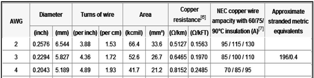
2 TABLE OF CONTENTS PAGE 1. COVER VAC WIRING LABEL 2. TABLEOFCONTENTS VAC CIRCUIT BREAKER EXAMPLES 3. ASSEM. IDENTIFICATION, OPTIONS, & UPGRADE INFO VOLT DC WIRING VACWIRING VOLT DC WIRING LABEL 5. TECHNICALNOTE-MOUNTINGREQUIREMENTS 10. CONDUCTOR AMPACITY CHART 2


3 The 8300 series models can be ordered as an option A to include a 30 ampere line/generator switch, or an ATS 301 can be added as a field installable upgrade. ATS Series Assembly Section Identification, with Options, & Upgrade Information 120VAC 30A Load Panel Breaker Cover (Deadfront) 120VAC 30A Load Panel Compartment DC Fuse Panel Compartment *Cover Plate for optional TempAssure Module. Parallax part # 4400TAU Converter Section The 8300 series can be field upgraded to provide temperature compensated output voltage by installing a model 4400TAU TempAssure module and sensor cable. ** Installation instructions are provided inside the kit. ** 3

4 1. Horizontal Mounting Only! Listed for indoor use only. Mount the 8300 Series assembly to a suitable mounting surface (wall or cabinet) with the base of assembly parallel to the floor. Leave the area in front of the control center open to the living area of the RV. Provide a minimum of 22 inches of clearance to the front of the 8300 Series assembly and adequate space behind the assembly for ventilation and wire routing. Refer to the Technical Note on the next page for additional information. 2. Panel rated for a maximum 30 ampere main breaker. Refer to the current NFPA 70 National Electrical Code Article 551 for maximum number of branch circuits allowed. See AC wiring label for list of suitable breakers for main and branch circuits. Use suitable filler plates for any unused breaker locations. 3. Install appropriately sized strain relief connectors on all AC or DC chassis knockouts removed to provide wire support and wire strain relief. 4. Connect 30 ampere supply line input (black - hot ) from Shore line cord or line generator switch output (if equipped) to the back-fed 30 ampere maximum main breaker line terminal. 5. NEC requires breaker hold-down bracket to secure 30 ampere main breaker. 6. Shore Line and 120 VAC load circuit (white) (common) neutrals connect to this isolated terminal bar. 7. Shore Line and 120 VAC load circuit (green) grounds and bonding conductor connect to this terminal bar. 8. AC bond routing hole for (# 8 AWG minimum required) AC bonding conductor VAC load breakers amperage rating chosen by AWG wire size used for the load circuit. Connect to (black) load circuit hot conductors. #14 AWG may connect to a maximum 15 ampere load breaker. #12 AWG may connect to maximum 20 ampere load breaker. 10. Connect black converter power hot lead to a 15 or 20 ampere (maximum) load breaker. Do not install converter section supply conductor to the main breaker Series AC Wiring Product shown dead front plate removed. *** Note- AC Breakers and DC load fuses not supplied with unit.*** 120VAC load breaker amperages shown for illustrative purposes only! Refer to item #9 at left regarding 120VAC load breakers. Refer to breakers and wiring labels for terminal torque ratings.. Electrical installation shall comply with the standards and safety requirements of the ANSI/RVIA 12V Standard for Low Voltage Systems in Conversion and Recreational Vehicles, NFPA 70 National Electrical Code and the NFPA 1192 Standard for Recreational Vehicles. 4
5 Parallax Power Supply Technical Note INFORMATION REGARDING MOUNTING CLEARANCES FOR PARALLAX POWER SUPPLY POWER CENTERS. The Owners Manual states that there must be a minimum of 22 inches of clearance provided to the front of the converter. Also, that adequate room should be left for wire routing and fan air intake located at the rear of the converter. The Owners Manual also states that the converter should not be mounted in zero clearance compartments because overheating and thermal shutdown will result. Regarding the 22-inch clearance requirement to the front of the converter: This statement was made in reference to the NEC article (b) exception No 1 pertaining to the AC panelboard section of the converter. It simply states that the power center panelboard must have 22 inches of clearance workspace after Installation. The panelboard is considered exposed where the panelboard face is within 2 inches of the finished surface to which it is mounted. A non-locking decretive door may be installed in front of the distribution panelboard however the panelboard must be within 2 inches of a finished surface, not including the door thickness. This is so that the panelboard can be readily accessed when the door is opened, exposing the 22-inch minimum clearance workspace but not allowing enough room between the panelboard and the door for storage. Regarding adequate room for wire routing and fan air intake: Our intent here is to state that there must be enough clearance around the converter to provide adequate intake airflow for cooling the converter system electronics. Also you must leave enough room for the AC and DC field wiring to be installed. In most cases leaving enough room for the field wiring will assure adequate air intake clearance. The main concern seems to be about the clearance to the converter exhaust louvers located in the front of the converter when a decorative door is added over the front of the converter. Because of physical design of the converter the exhaust louvers and the AC panelboard are in the same plane, hence the added door will not be greater than 2 inches from the louvers because of compliance with NEC (b) requirement for the panelboard. This will restrict to some degree the exhaust airflow. The only way to attack this problem is through trial and error. The converter must be placed under the clearance-limiting condition then its operation monitored to verify correct operation. If the converter shuts down due to overheating then the clearance area must be increased to allow proper airflow. The converter has been tested under completely blocked ventilation conditions and will not become a fire hazard but will not hold up to its full rated output load specifications. Please keep in mind that operating the converter under restricted air flow conditions will elevate the operating temperatures inside the converter and may reduce the life expectancy over time. The converter was designed to operate indefinitely at full (77f) ambient with the ventilation openings open to the living quarters. Parallax Power Supply will not be held liable for poor performance or failures of the converter due to restricted air flow installations. 5


6 8300 Series 120 VAC Wiring Label (located on back of metal dead front plate covering breaker compartment) 6


7 Examples of Listed Circuit Breaker Types Trademarks property of their respective owners. 7

8 Series DC Wiring 2 5 Electrical installation shall comply with the standards and safety requirements of the ANSI/RVIA 12V Standard for Low Voltage Systems in Conversion and Recreational Vehicles, NFPA 70 National Electrical Code and the NFPA 1192 Standard for Recreational Vehicles Converter DC positive output lead. 2. Converter reverse battery polarity protection fuses. Do not over-fuse. Refer to the DC wiring label. 3. Positive (POS) Terminal Connect to battery Positive wiring. # 8 CU AWG minimum w/ 90 degree Celsius insulation rating minimum required. Battery fuse or breaker required by NEC Code within 18 of the battery. Fuse or breaker amperage rating is determined per NEC Code (Table ) appropriate to AWG conductor size and insulation temperature rating of the conductor used. 4. DC Negative (NEG) Terminal Must connect to the battery negative and 12 volt branch circuit negatives. Use an appropriately sized conductor (# 8 CU AWG minimum w/ 90 degree Celsius insulation rating minimum) from the NEG terminal to an appropriately sized and rated terminal bar. Do not mount the terminal bar to the converter chassis. Mount the terminal bar behind the converter assembly to a suitable surface and provide an air gap or fire protection barrier material underneath the terminal bar. Connect the battery negative and the 12 volt branch circuit negatives to the terminal bar. Tighten all terminal bar connections to recommended specifications provided on or with the terminal bar Volt branch load circuit positive connection terminals. Fuse each load circuit per NEC Code (Table ) appropriate to AWG conductor size and insulation temperature rating of the conductor used. 6. Tighten all terminals to specifications provided on the DC fuse panel or the DC wiring label. 8

9 8300 Series DC Wiring Label (located inside door right side) 9

10 10
5300 Series Installation Guidelines
 1-800-443-4859 5300 Series Installation Guidelines WARNING: RISK OF ELECTRICAL SHOCK OR BURNS. THIS CONVERTER ASSEMBLY SHOULD BE INSTALLED BY A QUALIFIED ELECTRICIAN OR CERTIFIED RV TECHNICIAN. IMPROPER
RU SERIES UPGRADE TempAssure Compatible
 RU SERIES UPGRADE TempAssure Compatible This converter section has been designed as a converter section replacement in the following MagneTek or Parallax Power Supply series products and models with DC
dv Sentry TM 208V 600V INSTALLATION GUIDE Quick Reference ❶ How to Install Pages 6 14 ❷ Startup/Troubleshooting Pages WARNING
 dv Sentry TM 208V 600V INSTALLATION GUIDE FORM: DVS-IG-E REL. January 2018 REV. 003 2018 MTE Corporation High Voltage! Only a qualified electrician can carry out the electrical installation of this filter.
INSTRUCTIONS FOR THE RELIANCE Fast/Tran TM ARL0909 & ARL0909R
 INSTRUCTIONS FOR THE RELIANCE Fast/Tran TM ARL0909 & ARL0909R THE RELIANCE Fast/Tran IS NOT FOR "DO-IT-YOURSELF" INSTALLATION. It must be installed by a qualified electrician thoroughly familiar with all
Go Power! Manual. GP-1750HD Inverter GP-2500 Inverter
 Go Power! Manual GP-1750HD Inverter GP-2500 Inverter Go Power! Electric Inc. PO Box 6033 Victoria, BC V8P 5L4 Tel: 866-247-6527 Fax: 866-607-6527 Email: info@gpelectric.com Table of Contents 1. INTRODUCTION...
Permit for Charging Equipment Installation Electric Vehicle Supply Equipment (EVSE)
") Permit for Charging Equipment Installation Electric Vehicle Supply Equipment (EVSE) Town of Lake George, New York Compliance with the following permit will allow the installation and operation of electric
Permit for Charging Equipment Installation Electric Vehicle Supply Equipment (EVSE) Town of Lake George, New York Compliance with the following permit will allow the installation and operation of electric
Dimensions 12/800N 12/1200N D. DC to AC Power Inverters. OWNERS MANUAL for Models: OWNERS MANUAL April ISO 9001:2000 Certified Company
 Manufacturer of Dimensions Inverters 4467 White Bear Parkway St. Paul, MN 55110 Phone: 651-653-7000 Fax: 651-653-7600 E-mail: inverterinfo@sensata.com Web: www.dimensions.sensata.com OWNERS MANUAL April
MASTERsine Inverter PXA Series Installation Guide
 Backup Power System Expert TM MASTERsine Inverter PXA Series Installation Guide Important Safety Instructions IMPORTANT: Read and save this Installation Guide for future reference. This chapter contains
DC AC POWER INVERTER. LIV 10 / LIV 20 / LIV 30 User Manual
 DC AC POWER INVERTER LIV 10 / LIV 20 / LIV 30 User Manual Save This Manual Please read this manual carefully prior to storage, installation, wiring, operation and maintenance of the Power Inverter. This
MIL-24/2600Q MIL-24/3200DQ
 Manufacturer of Dimensions TM Inverters 4467 White Bear Parkway St. Paul, MN 55110 Phone: 651-653-7000 Fax: 651-653-7600 E-mail: inverterinfo@sensata.com Web: www.dimensions.sensata.com 121473B OWNER'S
SAVE THESE INSTRUCTIONS
 READ AND FOLLOW ALL SAFETY INSTRUCTIONS! SAVE THESE INSTRUCTIONS AND DELIVER TO OWNER AFTER INSTALLATION IMPORTANT SAFEGUARDS When using electrical equipment, basic safety precautions should always be
CHILLER MODEL NO. YS SOLID STATE STARTER, MODEL NO. SSS, L B OPTIONAL FACTORY INSTALLED DISCONNECT SWITCH AMPS OR
 WIRING DIAGRAMS CONTRACTOR ORDER NO. JCI CONTRACT NO. JCI ORDER NO. Supersedes: 160.80-PW4 (1099) Form: 160.80-PW4 (215) FIELD CONNECTIONS ROTARY SCREW CHILLER WITH GRAPHIC CONTROL CENTER AND YORK MOD
Electrical Installation
 Electrical Installation Symmetra LX Tower UPS Models 200 V, 4-8 kva 208/240 V, 4-8 kva 220/230/240 V, 4-8 kva 200 V, 4-16 kva 208/240 V, 4-16 kva 220/230/240 V, 4-16 kva Important Safety Messages SAVE
Raritan PX. Power Cord Installation Guide. Safety Guidelines. Safety Instructions
 QS Rule Raritan PX Power Cord Installation Guide This installation guide explains how to install power cords on Raritan PX products that do not come with a factory installed power cord. This type of product,
High Frequency SineWave Guardian TM
 High Frequency SineWave Guardian TM 380V 480V INSTALLATION GUIDE FORM: SHF-IG-E REL. January 2018 REV. 002 2018 MTE Corporation High Voltage! Only a qualified electrician can carry out the electrical installation
INSTRUCTIONS FOR THE RELIANCE CONTROLS ARM SERIES AUTOMATIC TRANSFER SWITCH
 INSTRUCTIONS FOR THE RELIANCE CONTROLS ARM SERIES AUTOMATIC TRANSFER SWITCH THE RELIANCE CONTROLS ARM SERIES AUTOMATIC TRANSFER SWITCH IS NOT FOR "DO-IT-YOURSELF" INSTALLATION. It must be installed by
SineWave Guardian TM 380V 600V INSTALLATION GUIDE. Quick Reference. ❶ How to Install Pages 6 17 ❷ Startup/Troubleshooting Pages WARNING
 SineWave Guardian TM 380V 600V INSTALLATION GUIDE FORM: SWG-IG-E REL. October 2018 REV. 003 2018 MTE Corporation High Voltage! Only a qualified electrician can carry out the electrical installation of
S150,S300 Series Pure Sine Wave Inverter User s Manual
 S150,S300 Series Pure Sine Wave Inverter User s Manual List of contents 1. Important Safety Instructions 3 1-1 General Safety Precautions 3 1-2 Precautions When Working With Batteries.. 3 2. Features...
ADI-125/750 ADI-125/1500 ADI-125/2500
 Manufacturer of Dimensions TM Inverters 4467 White Bear Parkway St. Paul, MN 55110 Phone: 651-653-7000 Fax: 651-653-7600 E-mail: inverterinfo@sensata.com Web: www.dimensions.sensata.com 121094B OWNERS
MODEL 6010A 6 12 VOLT BATTERY CHARGER ASSOCIATE
 MODEL 600A 6 VOLT BATTERY CHARGER ASSOCIATE IMPORTANT SAFETY INSTRUCTIONS. SAVE THESE INSTRUCTIONS. This manual contains important safety and operating instructions for the battery charger you have purchased.
Monicon Instruments Co., Ltd. CHR-1285/2485 CHR-1285/2485 BATTERY CHARGER
 CHR-1285/2485 BATTERY CHARGER TEL:886-4-2238-0698 FAX:886-4-2238-0891 Web Site:http://www.monicon.com.tw E-mail:sales@monicon.com.tw Copyright 2007 Monicon Instruments Co., Ltd. All right reserved. Contents
GP-1000 Inverter. Go Power! Electric Inc. PO Box 6033 Victoria, BC V8P 5L4 Tel: Fax:
 Go Power! Manual GP-1000 Inverter Go Power! Electric Inc. PO Box 6033 Victoria, BC V8P 5L4 Tel: 866-247-6527 Fax: 866-607-6527 Email: info@gpelectric.com Table of Contents 1. INTRODUCTION 3 2. SPECIFICATIONS
Art. No. EC-315. Art. No. EC-330. Art. No. EC-340 SWITCH-MODE BATTTERY CHARGER CONTENTS IMPORTANT SAFETY PRECAUTIONS... 2
 SWITCH-MODE BATTTERY CHARGER CONTENTS IMPORTANT SAFETY PRECAUTIONS... 2 DESCRIPTION AND FEATURES... 3 CHARGING STAGES... 4 Art. No. EC-315 Art. No. EC-330 Art. No. EC-340 PROTECTIONS... 5 INSTALLATION...
Safety and General Information
 Safety and General Information Symmetra LX Tower Rack-Mount UPS Models 200 V, 4-8 kva 208/240 V, 4-8 kva 220/230/240 V, 4-8 kva 200 V, 4-16 kva 208/240 V, 4-16 kva 220/230/240 V, 4-16 kva Important Safety
Installation Instructions
 NOTE: Read the entire instruction manual before starting the installation. This symbol indicates a change since the last issue. SAFETY CONSIDERATIONS Installing and servicing air conditioning equipment
AUTO CHARGE DUAL MODEL #: AUTOMATIC DUAL OUTPUT BATTERY CHARGER INSTRUCTION MANUAL. Ph: Fax:
 INSTRUCTION MANUAL AUTO CHARGE DUAL AUTOMATIC DUAL OUTPUT BATTERY CHARGER MODEL #: 091-145-12 INPUT: 120 Volt, 50/60 Hz, 3.5 Amps OUTPUT BAT 1: 10 Amps OUTPUT BAT 2: 10 Amps File: IM_091-145-12_revb.indd
Installation Instructions Electric Heaters 5 20 kw
 Small Packaged Products to 5 Tons Accessory Electric Heaters Cancels: IIK 564A--1 IIK 564A-- 11-01 Installation Instructions Electric Heaters 5 0 kw NOTE: Read the entire instruction manual before starting
FIELD CONNECTIONS FOR YK CHILLER (STYLE G) OPTIVIEW CONTROL CENTER WITH REMOTE MEDIUM VOLTAGE SSS
 OPTIVIEW CONTROL CENTER WITH REMOTE MEDIUM VOLTAGE SSS") Supersedes: 160.75-PW2 (508) Form 160.75-PW2 (311) FIELD CONNECTIONS FOR YK CHILLER (STYLE G) OPTIVIEW CONTROL CENTER WITH REMOTE MEDIUM VOLTAGE SSS WIRING DIAGRAM CONTRACTOR ORDER NO. YORK CONTRACT NO.
Supersedes: 160.75-PW2 (508) Form 160.75-PW2 (311) FIELD CONNECTIONS FOR YK CHILLER (STYLE G) OPTIVIEW CONTROL CENTER WITH REMOTE MEDIUM VOLTAGE SSS WIRING DIAGRAM CONTRACTOR ORDER NO. YORK CONTRACT NO.
INSTALLATION MANUAL MODEL #100947, AMP MODEL #100949, AMP RELIANCE CONTROLS ARL SERIES AUTOMATIC TRANSFER SWITCH
 INSTALLATION MANUAL MODEL #100947, 100950 50 AMP MODEL #100949, 100952 100 AMP RELIANCE CONTROLS ARL SERIES AUTOMATIC TRANSFER SWITCH REGISTER YOUR PRODUCT ONLINE at championpowerequipment.com or visit
RT Series Step Down Transformer for RT Series UPS 6-10kVA UL Input Vac Output Vac User Guide
 RT Series Step Down Transformer for RT Series UPS 6-10kVA UL Input 208-240 Vac Output 208-120 Vac User Guide UNLESS SPECIFICALLY AGREED TO IN WRITING, SELLER (A) MAKES NO WARRANTY AS TO THE ACCURACY, SUFFICIENCY
WF-5110R True Sine Wave Inverter
 Operator s Manual WF-5110R True Sine Wave Inverter WF-9900 Series WF-5110R ( The Inverter model number is located on the label on top of the enclosure) Distributed in the U.S.A. and Canada by ARTERRA DISTRIBUTION
This is intended to provide uniform application of the codes by the plan check staff and to help the public apply the codes correctly.
 SUPPLEMENTAL CORRECTION SHEET FOR SOLAR PHOTOVOLTAIC SYSTEMS (ELEC) This is intended to provide uniform application of the codes by the plan check staff and to help the public apply the codes correctly.
AUTO CHARGE 12 HO MODEL #: MODEL #: MODEL #: AUTOMATIC SINGLE OUTPUT BATTERY CHARGER INSTRUCTION MANUAL
 INSTRUCTION MANUAL AUTO CHARGE 12 HO AUTOMATIC SINGLE OUTPUT BATTERY CHARGER MODEL #: 091-170-6 MODEL #: 091-170-12 MODEL #: 091-170-24 File: IM_091-170-xx_revd.indd Rev: D Revised By: MFG Date: 10-23-2013
PUMP PLUS 2000 PLC MODEL #: PP AUTOMATIC DUAL OUTPUT BATTERY CHARGER INSTRUCTION MANUAL
 INSTRUCTION MANUAL PUMP PLUS 2000 PLC AUTOMATIC DUAL OUTPUT BATTERY CHARGER Supplied with Dual Bar Graph Display MODEL #: 091-237-12-PP INPUT: 120 Volt, 60 Hz, 3.5 Amps OUTPUT BATTERY 1 and 2: 15 or 18
Data Bulletin. Wire Temperature Ratings and Terminations INTRODUCTION WHY ARE TEMPERATURE RATINGS IMPORTANT?
 Data Bulletin March 2002 Lexington, KY, USA Wire Temperature Ratings and Terminations INTRODUCTION WHY ARE TEMPERATURE RATINGS IMPORTANT? Table 1: Insulation Type Figure 1: Figure 2: Ampacity of a 1/0
Installation and Operation Guide. Tundra HD 2500 Power Inverter. for the. Webasto BlueCool Truck System
 Installation and Operation Guide Tundra HD 2500 Power Inverter for the Webasto BlueCool Truck System www.tundrainternational.com www.techwebasto.com BCTSP0063A Table of Contents 1. Introduction 4 1.1 Disclaimer.................................................................................
model ps600 Address all communications and shipments to: FEDERAL SIGNAL CORPORATION
 MODEL: PS600 HZ: 60 A model ps600 installation and service manual for federal model ps600 FEDERAL SIGNAL CORPORATION POWER SUPPLY VOLTS: SERIES: 120VAC FEDERAL SIGNAL CORPORATION UNIVERSITY PARK, IL. U.S.A.
BATTERY SAVER LOW RIPPLE HO
 INSTRUCTION MANUAL BATTERY SAVER LOW RIPPLE HO LOW RIPPLE POWER SUPPLY / AUTOMATIC LOAD SWITCH FOR 12VDC VEHICLE SYSTEMS MODEL #: 091-195-12 INPUT: 120 Volt, 50/60 Hz, 4.5 Amps RMS OUTPUT: 13.2 Volts DC,
INSPECTOR LINE LOAD SIMULATOR INSTRUCTION MANUAL TASCO, INC.
 INSPECTOR LINE LOAD SIMULATOR INSTRUCTION MANUAL INS120P TASCO, INC. THIS TESTER IS DESIGNED FOR USE ONLY BY QUALIFIED ELECTRICIANS. IMPORTANT SAFETY WARNINGS mwarning Read and understand this material
OWNER S MANUAL AND INSTALLATION INSTRUCTIONS
 EmerGen Switch Manual Transfer Switch OWNER S MANUAL AND INSTALLATION INSTRUCTIONS For A Series Models 6-5001, 6-7501, 10-7501, 10-12K1 PLEASE READ THIS MANUAL IN ITS ENTIRETY BEFORE INSTALLING AND/OR
Powering the RV Adventure
 Powering the RV Adventure 4400/5400 Series 8300 Series ALS Series ATS Series TCRU Series Powering the RV Adventure Welcome Parallax Power Supply is a name you can trust. We are the pioneers of RV power
1000 Watt Pure Sine Wave Power Inverter, Users Manual
 WF-5100 Series 1000 Watt Pure Sine Wave Power Inverter, Users Manual Distributed in the USA and Canada by Arterra Distribution 2021 Aeroplex Drive North. Elkhart, IN. 46514 Phone: 877-294-8997, Fax: 547-294-8698
Installing Power Components
 This chapter provides instructions on how to install and reinstall power components in the Cisco NCS 4016 chassis. It also covers connecting and disconnecting power and powering on the chassis. The Cisco
Smart Battery Charger GPC-35-MAX GPC-45-MAX GPC-55-MAX GPC-75-MAX GPC-100-MAX. Owner s Manual
 Smart Battery Charger GPC-35-MAX GPC-45-MAX GPC-55-MAX GPC-75-MAX GPC-100-MAX Owner s Manual Table of Contents Important Safety Instructions 2 Features 3 Installation Guidelines 5 Warranty 8 1.0 Important
LPC 20 MODEL #: LOW PROFILE CHARGER AUTOMATIC SINGLE OUTPUT BATTERY CHARGER INSTRUCTION MANUAL
 INSTRUCTION MANUAL LPC 20 LOW PROFILE CHARGER AUTOMATIC SINGLE OUTPUT BATTERY CHARGER Unit supplied with one of these displays MODEL #: 091-207-12 INPUT: 120 Volt, 50/60 Hz, 7 Amps OUTPUT: 20 Amps File:
For Use with Model(s):all electric models
:all electric models") ELECTRIC Installation FREE-STANDING Manual For Use with Model(s):all electric models CONVECTION RANGE Table of Contents Important Safety Instructions... 1 Installation... 2 Before You Begin... 2 Tools
ELECTRIC Installation FREE-STANDING Manual For Use with Model(s):all electric models CONVECTION RANGE Table of Contents Important Safety Instructions... 1 Installation... 2 Before You Begin... 2 Tools
OBE, OBEXU, ON BOARD Battery Chargers
 C O R P O R A T IO N O P E R A T I N G I N S T R U C T I O N S OBE, OBEXU, ON BOARD Battery Chargers INTRODUCTION: These chargers are designed for the permanent installation on battery powered vehicles
Installation Instructions Electric Heaters 5 20 kw
 Small Packaged Products 2 to 5 Tons Accessory Electric Heaters Cancels: IIK 564A-24-2 IIK 564A-24- -02 Installation Instructions Electric Heaters 5 20 kw NOTE: Read the entire instruction manual before
90.2 Scope. The installation of electrical conductors, equipment and raceways for:
 NEC Generator Primer Rules on the installation of generators and transfer switches 1 90.2 Scope The installation of electrical conductors, equipment and raceways for: public and private premises Conductors
Photovoltaic Solar Plan Review
 PAIGE B. VAUGHAN, CBO Director of Building and Safety Phone (310) 605-5509 Fax Line (310) 605-5598 E-mail:lbutler@comptoncity.org Building & Safety Department Photovoltaic Solar Plan Review Plan Check
Quik-Spec Coordination Panelboard
 Read and retain for future reference Quik-Spec Coordination Panelboard Instruction Leaflet 3A1071 RevD Section TABLE OF CONTENTS Page Danger and warnings for installation of the equipment.............3-4
AUTO CHARGE D2 MODEL #: AUTOMATIC TRIPLE OUTPUT BATTERY CHARGER INSTRUCTION MANUAL
 INSTRUCTION MANUAL AUTO CHARGE D2 AUTOMATIC TRIPLE OUTPUT BATTERY CHARGER Designed Specifically for Vehicles with DDEC ENGINES MODEL #: 091-74-12 INPUT: 120 Volt, 60 Hz, 8 Amps OUTPUT VEHICLE BATTERY 1
ACC Series Power Conditioner OPERATION & INSTALLATION MANUAL
 ACC Series Power Conditioner OPERATION & INSTALLATION MANUAL PHASETEC digital power conditioners are designed to safely operate electrical equipment in the harshest power quality environments. With a wide
Power and Cooling. Chassis Power System
 This chapter describes the Cisco NCS 6000 Series Routers power and cooling systems. It also provides the power, grounding, and cooling requirements for the installation site to help you plan the site facilities
QSSE, QSSEX INDUSTRIAL Battery Chargers
 C O R P O R A T IO N O P E R A T I N G I N S T R U C T I O N S QSSE, QSSEX INDUSTRIAL Battery Chargers INTRODUCTION The QSE line are electronically controlled float chargers. The batteries are brought
Optimizing Emergency Power Systems for Health Care Applications
 2018 Annual Conference Optimizing Emergency Power Systems for Health Care Applications aka: Using the latest code changes to improve system reliability and maybe even save some $$$... Overview Michigan
WF-5110R True Sine Wave Inverter
 Operator s Manual WF-5110R True Sine Wave Inverter WF-9900 Series WF-5110R ( The Inverter model number is located on the label on top of the enclosure) Distributed in the U.S.A. and Canada by ARTERRA DISTRIBUTION
Power Inverter 400 MW Owner s Manual
 Power Inverter 400 MW 1204 Owner s Manual For safe and optimum performance, the Power Inverter must be used properly. Carefully read and follow all instructions and guidelines in this manual and give special
Instruction Bulletin Dual Sub-Feed Circuit Breaker and Adapter Kit Installation onto an NQ Panelboard Class 1640
 Instruction Bulletin Dual Sub-Feed Circuit Breaker and Adapter Kit Installation onto an NQ Panelboard Class 1640 80043-731-02 10/2009 Peru, IN, USA Retain for future use. Introduction This bulletin contains
Cabinet and Rack Installation
 Cabinet and Rack Requirements, page 1 Cisco MDS 9000 Family Telco and EIA Shelf Bracket, page 3 Cabinet and Rack Requirements This section provides the Cisco MDS 9000 Family requirements for the following
Installation and Operation Guide for PD4100 Series Power Control Centers
 Installation and Operation Guide for PD4100 Series Power Control Centers Extended warranties are available for purchase at www.progressivedyn.com Member Thank you for selecting Progressive Dynamics as
SECTION ENCLOSED SWITCHES AND CIRCUIT BREAKERS
 SECTION 26 28 16 ENCLOSED SWITCHES AND PART 1 - GENERAL 1.1 SUMMARY A. Section includes the following individually mounted, enclosed switches and circuit breakers rated 600V AC and less: 1. Fusible switches.
SUPPLEMENTAL CORRECTION SHEET FOR SOLAR PHOTOVOLTAIC SYSTEMS - ELECTRICAL
 SUPPLEMENTAL CORRECTION SHEET FOR SOLAR PHOTOVOLTAIC SYSTEMS - ELECTRICAL This is intended to provide uniform application of the codes by the plan check staff and to help the public apply the codes correctly.
Technical Manual. DLM Module. This manual should remain with the unit.
 Technical Manual DLM Module This manual should remain with the unit. Safety Rules SAVE THESE INSTRUCTIONS! Read the following information carefully before attempting to install, operate or service this
9/16/2010. Chapter , The McGraw-Hill Companies, Inc. TRANSMISSION SYSTEMS. 2010, The McGraw-Hill Companies, Inc.
 Chapter 3 TRANSMISSION SYSTEMS 1 Transmitting large amounts of electric energy over long distances is accomplished most efficiently by using high-voltages. Without transformers the widespread distribution
AUTO CHARGE D PUMP PLUS
 INSTRUCTION MANUAL AUTO CHARGE D PUMP PLUS AUTOMATIC DUAL OUTPUT BATTERY CHARGER Designed Specifically for Vehicles with DDEC ENGINES MODEL #: 091-9-DPP INPUT: 120 Volt, 60 Hz, 8 Amps OUTPUT VEHICLE BATTERY:
PUMP PLUS 1000 PLC MODEL #: PP AUTOMATIC SINGLE OUTPUT BATTERY CHARGER INSTRUCTION MANUAL
 INSTRUCTION MANUAL PUMP PLUS 1000 PLC AUTOMATIC SINGLE OUTPUT BATTERY CHARGER Unit supplied with one of these displays MODEL #: 091-215-12-PP INPUT: 120 Volt, 60 Hz, 3.5 Amps OUTPUT BATTERY 1 and 2: 15
USER MANUAL FOR 2000 WATTS POWER INVERTER USER S MANUAL--Read before operating this equipment
 USER MANUAL FOR 2000 WATTS POWER INVERTER Your 2000 watts power inverter converts 12-volt vehicle battery power into 230 volts of AC power. You can use the inverter in your vehicle to operate many types
Electric Vehicle Charging Station Article California Electrical code (CEC) General Requirements:
 General Requirements:") Checklist for Non-Residential Electric Vehicle Charging Station Article 625 2016 California Electrical code (CEC) General Requirements: Level 1 Charger: 110V dedicated 20 amp circuit No electrical plans
Checklist for Non-Residential Electric Vehicle Charging Station Article 625 2016 California Electrical code (CEC) General Requirements: Level 1 Charger: 110V dedicated 20 amp circuit No electrical plans
Cabinet and Rack Installation
 APPENDIXA This appendix includes the following information: Cabinet and Rack Requirements, page A-1 Cisco MDS 9000 Family Telco and EIA Shelf Bracket, page A-3 Cabinet and Rack Requirements This section
AUTO CHARGE 4000 MODEL #: LOW PROFILE CHARGER AUTOMATIC DUAL OUTPUT BATTERY CHARGER INSTRUCTION MANUAL
 INSTRUCTION MANUAL AUTO CHARGE 4000 LOW PROFILE CHARGER AUTOMATIC DUAL OUTPUT BATTERY CHARGER Unit supplied with this display MODEL #: 091-89-12 INPUT: 120 Volt, 50/60 Hz, 5 Amps OUTPUT: 45 Amps File:
Matrix APAX. 380V-415V 50Hz TECHNICAL REFERENCE MANUAL
 Matrix APAX 380V-415V 50Hz TECHNICAL REFERENCE MANUAL WARNING High Voltage! Only a qualified electrician can carry out the electrical installation of this filter. Quick Reference ❶ Performance Data Pages
OWNERS MANUAL JANUARY 2007 ISO
 Manufacturer of Dimensions TM Inverters 4467 White Bear Parkway St. Paul, MN 55110 Phone: 651-653-7000 Fax: 651-653-7600 E-mail: inverterinfo@sensata.com Web: www.dimensions.sensata.com 121231B OWNERS
Battery Equalizer. Table of Contents Introduction. 2. Specifications.. 3. Theory of Operation Typical Applications... 5
 Owners Manual 9$ '11* XD :,U7G/ Battery Equalizer 6$H0U7L H0V8 Table of Contents Introduction. 2 Specifications.. 3 Theory of Operation... 4 Typical Applications...... 5 Installation Instructions.....
PD404-AN V analog control 4 Channel x 500 W Dimmer & Switch Packs ANALOG 0-10 V. Serial Number
 0-10V analog control 4 Channel x 500 W Dimmer & Switch Packs ANALOG 0-10 V 4 circuit Analog 1-10V 4 x 4 A. Dimmer pack Serial Number Dimmers Indicators Digital Lighting Systems,Inc Info@digitallighting.com
Electric Range installation manual
 Electric Range installation manual This manual is made with 100% recycled paper. imagine the possibilities ENGLISH Thank you for purchasing this Samsung product. To receive more complete service, please
AUTO CHARGE LPC SERIES
 INSTRUCTION MANUAL FILE: IM_091-206-12_revB REV: B REVISED BY: THN DATE: 09-17-2012 AUTO CHARGE LPC SERIES MODEL #091-206-12 LPC STANDARD DISPLAY INPUT: 115 volt, 50/60 Hz, 13 amps OUTPUT: 80 AMPERES 3
Instruction Bulletin NF Panelboard Dual Sub-Feed Circuit Breaker Adapter Kit Installation onto an NF Panelboard Class 1670
 Instruction Bulletin NF Panelboard Dual Sub-Feed Circuit Breaker Adapter Kit Installation onto an NF Panelboard Class 1670 80043-760-03 06/2009 Peru, IN, USA Retain for future use. Introduction This bulletin
OBAE, OBAEXU, ON BOARD Battery Chargers
 C O R P O R A T IO N O P E R A T I N G I N S T R U C T I O N S OBAE, OBAEXU, ON BOARD Battery Chargers INTRODUCTION: The OBAE line of chargers are designed for the permanent installation on battery powered
SECTION ENCLOSED SWITCHES AND CIRCUIT BREAKERS
 PART 1 - GENERAL 1.1 DESCRIPTION SECTION 26 29 21 ENCLOSED SWITCHES AND CIRCUIT BREAKERS SPEC WRITE NOTE: Delete between // // if not applicable to project. Also delete any other item or paragraph not
INSTALLATION INSTRUCTIONS
 INSTALLATION INSTRUCTIONS Universal Air Series!! NOTE!! Covers the following model: 6000 Series 85-0100B-AZ Rev 0 5/07 To ensure that the system is installed properly, provide your electrician with these
Installation and Operation Guide for PD1200 Series Pure Sine Wave Inverters
 Installation and Operation Guide for PD10 Series Pure Sine Wave Inverters Member The PD10 Series Inverter is a 1 VAC, 60 Hz, pure sine wave inverter with integrated transfer switch. It has been robustly
INSTALLATION INSTRUCTIONS FOR EGA AND EGH SERIES ELECTRIC HEATERS IN V OR H SERIES UNITS
 INSTALLATION INSTRUCTIONS FOR EGA AND EGH SERIES ELECTRIC HEATERS IN V OR H SERIES UNITS NOTE TO INSTALLER The words SHALL and MUST indicate a requirement which is essential to satisfactory and safe product
Quik-Spec Coordination Panelboard Specifications
 Quik-Spec Coordination Panelboard Specifications 30A - 400A Fusible Panelboards SECTION 26 24 XX (This Specification references CSI MasterFormat 2004) FUSIBLE BRANCH CIRCUIT PANELBOARDS PART 1 1.01 SUMMARY
Start UP Guide. Symmetra LX Tower Rack-Mount. UPS Models 200 V, 4-8 kva 208/240 V, 4-8 kva 220/230/240 V, 4-8 kva
 Start UP Guide Symmetra LX Tower Rack-Mount UPS Models 200 V, 4-8 kva 208/240 V, 4-8 kva 220/230/240 V, 4-8 kva 200 V, 4-16 kva 208/240 V, 4-16 kva 220/230/240 V, 4-16 kva Important Safety Messages SAVE
Electrical Safety. Electrical Safety Webinar. Electrical. Printing Industries Alliance Printing Industries Alliance 1
 Webinar 1 Electrical 2 1 Webinar Introduction An average of one worker is electrocuted on the job every day There are four main types of electrical injuries: Electrocution (death due to electrical shock)
QPET, QPETXU Battery Chargers
 C O R P O R A T IO N O P E R A T I N G I N S T R U C T I O N S QPET, QPETXU Battery Chargers INTRODUCTION: The QPET line of chargers are designed for general purpose deep cycle batteries. They are an electronically
Switching DC Power Supply
 99 Washington Street Melrose, MA 02176 Phone 781-665-1400 Toll Free 1-800-517-8431 Visit us at www.testequipmentdepot.com Model 1693, 1694 Switching DC Power Supply INSTRUCTION MANUAL 1 Safety Summary
FLO Home TM G5 Model. Installation guide
 FLO Home TM G5 Model Installation guide Table of Contents Safety Instructions 3 Planning your Installation 4 Box Contents 5 Installing the Station 6 Setting the Current Limit 9 Light Indicator 11 Compliance
Design Standards NEMA
 Design Standards Although several organizations are involved in establishing standards for the design, construction, and application of motor control centers, the primary standards are established by UL,
OWNER S MANUAL. Model YUA2AMPCH 2 AMP Dual-Bank Automatic Battery Charger & Maintainer READ ENTIRE MANUAL BEFORE USING THIS PRODUCT
 Model YUA2AMPCH 2 AMP Dual-Bank Automatic Battery Charger & Maintainer Certified by California BCS Regulations OWNER S MANUAL READ ENTIRE MANUAL BEFORE USING THIS PRODUCT READ ENTIRE MANUAL BEFORE USING
Owner's Manual. GenReady Load Center and Transfer Switch. This manual should remain with the unit. Model Numbers. GenReady Basic Panelboard
 Owner's Manual GenReady Load Center and Transfer Switch 0054480 0054510 0054490 0054520 0054530 0054540 0054560 Model Numbers GenReady Basic Panelboard GenReady Advanced Panelboard with Operator GenReady
Microinverters and AC PV modules are becoming. Microinverters and AC PV Modules. Different Beasts. Perspectives on PV.
 Perspectives on PV Microinverters and AC PV Modules Are Different Beasts by John Wiles Microinverters and AC PV modules are becoming very common in residential and small commercial PV systems. See photos
Infinity 1U 19 Converter Shelf Models: J L224-48V to +24V, L V to -48V
 GE Critical Power Quick Start Guide Infinity 1U 19 Converter Shelf Models: J5964803 L224-48V to +24V, L225 +24V to -48V Edge Controller example Outputs RTNs Inputs RTNs Refer to Infinity Converter Brochure
AUTO CHARGE 4000 MODEL #: AUTOMATIC DUAL OUTPUT BATTERY CHARGER INSTRUCTION MANUAL. Ph: Fax:
 INSTRUCTION MANUAL AUTO CHARGE 4000 AUTOMATIC DUAL OUTPUT BATTERY CHARGER MODEL #: 091-89-12 INPUT: 120 Volt, 50/60 Hz, 8 Amps OUTPUT BATTERY CHARGER: 40 Amps OUTPUT BATTERY SAVER: 5 Amps File: IM_091-89-12_reve.indd
230VAC Power Inverter 400W Owner s Manual
 400W 230VAC Power Inverter 400W Owner s Manual For safe and optimum performance, the Enerdrive epower Inverter must be used properly. Carefully read and follow all instructions and guidelines in this manual
Installation Instructions Central Battery Units
 Phone: 605.542.4444 concealite.com! Installation Instructions s Please Save These Instructions Important Safeguards Read and Follow All Safety Instructions When using electrical equipment, basic safety
The Power of Reliability INSTRUCTION MANUAL
 The Power of Reliability INSTRUCTION MANUAL SAFETY & WARNINGS Read this manual carefully and understand all Warnings and Cautions before connections are made to the Inverter. If unsure about any aspects
TEMPORARY ELECTRIC WIRING FOR CARNIVALS, CONVENTIONS, EXHIBITIONS, FAIRS AND SIMILAR USES
 INFORMATION BULLETIN / PUBLIC - ELECTRICAL CODE REFERENCE NO.: LAMC 93.0230 Effective: 3-24-69 DOCUMENT NO. P/EC 2002-006 Revised: 11-17-00 Previously Issued As: RGA #7-69 TEMPORARY ELECTRIC WIRING FOR
DC to AC Power Inverters
 Manufacturer of Dimensions TM Inverters 4467 White Bear Parkway St. Paul, MN 55110 Phone: 651-653-7000 Fax: 651-653-7600 E-mail: inverterinfo@sensata.com Web: www.dimensions.sensata.com ISO 9001:2000 Certified